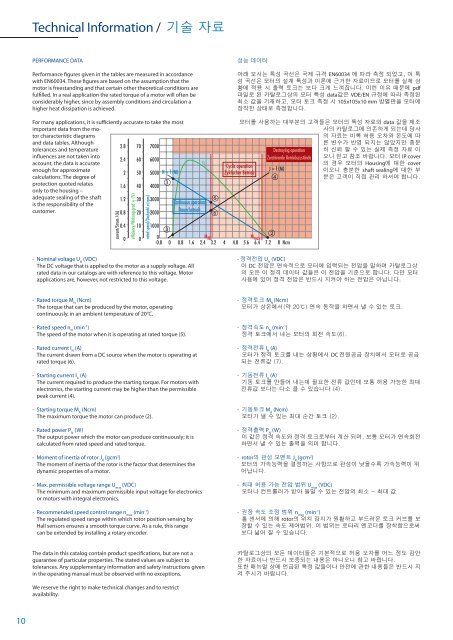
Technical Information / 기술 자료PERFORMANCE DATAPerformance figures given in the tables are measured in accordancewith EN60034. These figures are based on the assumption that themotor is freestanding and that certain other theoretical conditions arefulfilled. In a real application the rated torque of a motor will often beconsiderably higher, since by assembly conditions and circulation ahigher heat dissipation is achieved.성능 데이터아래 보시는 특성 곡선은 국제 규격 EN60034 에 따라 측정 되었고, 이 특성 곡선은 모터의 설계 특성과 이론에 근거한 자료이므로 모터를 실제 상황에 적용 시 출력 토크는 보다 크게 느껴집니다. 이런 이유 때문에 pdf파일로 된 카탈로그상의 모터 특성 data값은 VDE/EN 규정에 따라 측정된최소 값을 기재하고, 모터 토크 측정 시 105x105x10 mm 방열판을 모터에장착한 상태로 측정합니다.For many applications, it is sufficiently accurate to take the mostimportant data from the motorcharacteristic diagramsand data tables. Althoughtolerances and temperatureinfluences are not taken intoaccount, the data is accurateenough for approximatecalculations. The degree ofprotection quoted relatesonly to the housing –adequate sealing of the shaftis the responsibility of thecustomer.current/Strom I (A)2.82.421.61.20.80.40efficiency/Wirkungsgrad η (%)706050403020100rated speed/Drehzahl n (rpm)700060005000 N = f (M)400030002000ηContinuous operationDauerbetrieb모터를 사용하는 대부분의 고객들은 모터의 특성 자료와 data 값을 제조사의 카탈로그에 의존하게 되는데 당사의 자료는 비록 허용 오차와 온도에 따Cyclic operationZyklischer BetriebDestroying operationZerstörende BetriebszuständeJ = f (M)10000M NM max-0.8 0 0.8 1.6 2.4 3.2 4 4.8 5.6 6.4 7.2 8 Ncm른 변수가 반영 되지는 않았지만 충분히 신뢰 할 수 있는 실제 측정 자료 이오니 믿고 참조 바랍니다. 모터 IP cover의 경우 모터의 Housing에 대한 cover이오니 충분한 shaft sealing에 대한 부분은 고객이 직접 관리 하셔야 합니다.- Nominal voltage U N(V<strong>DC</strong>)The <strong>DC</strong> voltage that is applied to the motor as a supply voltage. Allrated data in our catalogs are with reference to this voltage. Motorapplications are, however, not restricted to this voltage.- 정격전압 U N(V<strong>DC</strong>)이 <strong>DC</strong> 전압은 연속적으로 모터에 입력되는 전압을 말하며 카탈로그상의 모든 이 정격 데이터 값들은 이 전압을 기준으로 합니다. 다만 모터사용에 있어 정격 전압은 반드시 지켜야 하는 전압은 아닙니다.- Rated torque M N(Ncm)The torque that can be produced by the motor, operatingcontinuously, in an ambient temperature of 20°C.- Rated speed n N(min -1 )The speed of the motor when it is operating at rated torque (5).- Rated current I N(A)The current drawn from a <strong>DC</strong> source when the motor is operating atrated torque (6).- Starting current I A(A)The current required to produce the starting torque. For motors withelectronics, the starting current may be higher than the permissiblepeak current (4).- Starting torque M A(Ncm)The maximum torque the motor can produce (2).- Rated power P N(W)The output power which the motor can produce continuously; it iscalculated from rated speed and rated torque.- Moment of inertia of rotor J R(gcm 2 )The moment of inertia of the rotor is the factor that determines thedynamic properties of a motor.- Max. permissible voltage range U max(V<strong>DC</strong>)The minimum and maximum permissible input voltage for electronicsor motors with integral electronics.- Recommended speed control range n max(min -1 )The regulated speed range within which rotor position sensing byHall sensors ensures a smooth torque curve. As a rule, this rangecan be extended by installing a rotary encoder.- 정격토크 M N(Ncm)모터가 상온에서(약 20℃) 연속 동작을 하면서 낼 수 있는 토크.- 정격속도 n N(min -1 )정격 토크에서 내는 모터의 회전 속도(6).- 정격전류 I N(A)모터가 정격 토크를 내는 상황에서 <strong>DC</strong> 전원공급 장치에서 모터로 공급되는 전류값 (7).- 기동전류 I A(A)기동 토크를 만들어 내는데 필요한 전류 값인데 보통 허용 가능한 최대전류값 보다는 다소 클 수 있습니다 (4).- 기동토크 M A(Ncm)모터가 낼 수 있는 최대 순간 토크 (2).- 정격출력 P N(W)이 값은 정격 속도와 정격 토크로부터 계산 되며, 보통 모터가 연속회전하면서 낼 수 있는 출력을 의미 합니다.- rotor의 관성 모멘트 J R(gcm 2 )모터의 가속능력을 결정하는 사항으로 관성이 낮을수록 가속능력이 뛰어납니다.- 최대 허용 가능 전압 범위 U max(V<strong>DC</strong>)모터나 컨트롤러가 받아 들일 수 있는 전압의 최소 ~ 최대 값- 권장 속도 조정 범위 n max(min -1 )홀 센서에 의해 rotor의 위치 감지가 원활하고 부드러운 토크 커브를 보장할 수 있는 속도 제어범위. 이 범위는 로타리 엔코더를 장착함으로써보다 넓어 질 수 있습니다.The data in this catalog contain product specifications, but are not aguarantee of particular properties. The stated values are subject totolerances. Any supplementary information and safety instructions givenin the operating manual must be observed with no exceptions.카탈로그상의 모든 데이터들은 기본적으로 허용 오차를 어느 정도 감안한 자료이나 반드시 보증되는 내용은 아니오니 참고 바랍니다.또한 매뉴얼 상에 언급된 특정 값들이나 안전에 관한 내용들은 반드시 지켜 주시기 바랍니다.We reserve the right to make technical changes and to restrictavailability.10
Engineering Reference / 참조사항MOTOR CHARACTERISTIC DIAGRAMS- Speed curve (blue)This curve shows the speed characteristic at constant voltage. Its endpoints are the no-load speed n 0(1) and the theoretical starting torqueM A(2).- Current curve (black)The current curve shows the relationship between current and torque.Its end points are the no-load current I 0(3) and the starting current I A(4).모터 특성표- 속도 곡선(파랑)일정한 입력 전압 하에서의 회전 속도 특성을 나타내며 끝 점은 무부하 속도 n 0(1)이며, 이론적인 기동 토크 M A(2)이다.- 전류 곡선(검정)전류와 토크사이의 상관 관계를 나타내며, 끝 점은 무부하 전류 I 0(3)이며기동 전류는 I A(4)이다.- Efficiency curve (green)The efficiency is the relationship between the mechanical power outputand the electrical power input.The curve shows the efficiency with the motor in cold condition; as themotor warms up, the curve shifts accordingly.- 효율 곡선(녹색)전기적인 입력과 기계적인 출력 사이의 상관 관계를 나타내며, 자료상의커브는 모터가 차가운 상태에서의 커브인 점 참조 바랍니다. 모터가 점차열을 받게 되면 커브도 약간 변하게 됩니다.- Rated torque M N, Starting torque M maxThe rated torque (red) is the limit of the continuous operation region(shaded blue). In the region between the rated torque and the maximumpermissible torque, the motor must only be used intermittently (shadedorange). Operating conditions above the maximum permissible torqueresult in demagnetization of the permanent magnets (shaded red).- 정격 토크 M N; 기동 토크 M max정격 토크(적색선)는 모터가 연속 동작이 가능한 구간 (푸른색 구간)이고, 정격 토크 구간과 기동 토크 구간 (오랜지색 구간)에서는 모터의 연속동작이 제한되고 간헐적인 사용만 가능한 구간을 의미 합니다. 그리고 최대 허용 토크 (적색 구간) 이상은 모터 내의 자성에 영향을 주는 구간으로이 영역에서 사용 시 즉시 모터에 악영향을 주게 됩니다.ENGINEERING REFERENCEIn the wide range of <strong>Dunkermotoren</strong> products, you will find a suitabledrive for almost any requirement in powers ranging from 1 - 530 Watt.Please also note our other product lines and catalogs (Brushless <strong>DC</strong><strong>Motors</strong>, AC motors).The following points should be taken into account when selectingmotors and gearboxes:- Which type of operation is required (continuous, intermittentor periodic operation)?- What is the working life expected of the motor?- What torque and speeds are required?- How much space is available for the motor?- How high is the available voltage? <strong>DC</strong> or AC?- Are there special environmental conditions (temperature,humidity, vibration, ...)?- To what degree can heat from the motor be disposed of?- Are there exceptional axial and radial shaft loads to consider?- What demands are made of the motor control electronics?- Is the motor to be controlled online via a bus system?- Do you need a brake, an encoder or a non-reversing device?참조사항던커모터에서 공급하는 1 ~ 530Watt range의 폭넓은 모터 제품군과 각종추가 사양들로 원하시는 모든 solution을 제공 드립니다.당사의 모터 및 감속기 등 제품 선택시 아래 사항들을 참조 바랍니다.- 모터의 동작 형태는 ? ( 연속동작, 간헐적인 동작 등등 )- 모터의 요구 수명은 ?- 요구 하시는 모터의 토크와 속도는 ?- 모터 장착에 허용 가능한 공간은 ?- 모터의 사용 전압은 ? <strong>DC</strong> 또는 AC- 특별한 사용 조건은 ? (고온, 다습, 진동 등등 )- 특별한 모터의 제한 온도가 있는지 ?- 특별히 모터 샤프트에 가해지는 수직 또는 수평부하가 있는지 ?- 모터 컨트롤러도 함께 필요한지 ?- 통신인터페이스를 통해 모터를 제어해야 하는지?- 브레이크, 엔코더등 다른 필요한 사항은 ?By dimensioning a suitable motor, determining the required torque playsa decisive role in avoiding thermal overload of the motor in service. Inthe assembly of a drive system consisting of motor and control electronics,it is important to ensure that permissible values for the motorare not exceeded by outputs from the electronics.Depending on the speed of rotation required, a motor or a motorgearboxcombination may be selected. The choice of a reductiongearbox will largely depend on the recommended maximum torquein continuous operation. For intermittent duty, loading above the ratedtorque is possible.When choosing a motor after deciding on the gearbox, the followingapplies:M motor= M gearbox/ (i x η)We will be pleased to carry out a precise adaptation of a motor to yourservice conditions.제품 선택시 과부하로 인한 문제 발생을 피하기 위하여 먼저 사용 용도에필요한 토크를 정확히 확인하시기 바랍니다.모터와 컨트롤러의 조합에 있어 모터에 허용 가능한 값들을 확인 하시고최종 필요한 속도에 따라 적당한 감속기를 선택 하십시오. 또한 감속비선택에 있어 연속 동작 허용 토크를 참조 하십시오.감속기의 정격토크보다 약간 큰 부하에 대해 간헐적인 동작 사용은 전혀문제 없습니다.감속기 선택 후 모터 선택시 다음을 참조하시기 바랍니다.M motor= M gearbox/( 감속비 x 효율 )정확한 모터 및 감속기 조합 선택에 도움이 되셨을 것으로 기대합니다.11
- Page 4 and 5: Why Dunkermotoren? / 왜 던커모
- Page 6 and 7: Our Product Range / 제품군DC-Mot
- Page 9: GR/G Selection GuideGR/G 모터 선
- Page 13 and 14: GR 23, 4 WDimensions in mm / 규격
- Page 15 and 16: G 30.2, 4 WDimensions in mm / 규
- Page 17 and 18: G 30.1 / G 30.1 S, 6 W / 7 WDimensi
- Page 19 and 20: G 30.0 / G 30.0 S, 10 W / 11 WDimen
- Page 21 and 22: GR 42x25, 15 WDimensions in mm /
- Page 23 and 24: GR 42x40, 20 WDimensions in mm /
- Page 25 and 26: GR 51x30, 40 WDimensions in mm /
- Page 27 and 28: GR 51x58, 60 WDimensions in mm /
- Page 29 and 30: GR 53x30, 40 WDimensions in mm /
- Page 31 and 32: GR 53x58, 60 WDimensions in mm /
- Page 33 and 34: GR 53 SI, 40 - 60 WDimensions in mm
- Page 35 and 36: GR 63x25, 50 WDimensions in mm /
- Page 37 and 38: GR 63x55, 100 WDimensions in mm /
- Page 39 and 40: GR 63Sx55, 130 WDimensions in mm /
- Page 41 and 42: GR 63 SI, 50 - 100 WDimensions in m
- Page 43 and 44: GR 80x40, 120 WDimensions in mm /
- Page 45 and 46: GR 80x80, 240 WDimensions in mm /
- Page 47 and 48: PLG/SG Gears for DC Motors /DC 모
- Page 49 and 50: PLG 24Lengths L motor gearbox combi
- Page 51 and 52: PLG 30Lengths L motor gearbox combi
- Page 53 and 54: PLG 30 HLengths L motor gearbox com
- Page 55 and 56: PLG 32Lengths L motor gearbox combi
- Page 57 and 58: PLG 32 HLengths L motor gearbox com
- Page 59 and 60: PLG 42 KLengths L motor gearbox com
- Page 61 and 62:
PLG 42 SLengths L motor gearbox com
- Page 63 and 64:
PLG 52Lengths L motor gearbox combi
- Page 65 and 66:
PLG 52 H - Low NoiseLengths L motor
- Page 67 and 68:
PLG 60Lengths L motor gearbox combi
- Page 69 and 70:
PLG 63Lengths L motor gearbox combi
- Page 71 and 72:
PLG 75Lengths L motor gearbox combi
- Page 73 and 74:
SG 45Lengths L motor gearbox combin
- Page 75 and 76:
SG 62Lengths L motor gearbox combin
- Page 77 and 78:
SG 80Lengths L motor gearbox combin
- Page 79 and 80:
SG 120Lengths L motor gearbox combi
- Page 81 and 82:
Data / 기술자료 E 38 R E 46 A E
- Page 83 and 84:
Magnetic pulse generators /마그
- Page 85 and 86:
Incremental Encoders for GR/G Motor
- Page 87 and 88:
Controller RS 200 / 컨트롤러 RS
- Page 89 and 90:
BGE 3508/6005Dimensions in mm / 규
- Page 91 and 92:
BGE 3515/6010Dimensions in mm / 규
- Page 93 and 94:
4 Connector for protection covers,