Kollektor-Gleichstrommotoren Baureihe GR/G - Dunkermotoren
Kollektor-Gleichstrommotoren Baureihe GR/G - Dunkermotoren
Kollektor-Gleichstrommotoren Baureihe GR/G - Dunkermotoren
- No tags were found...

You also want an ePaper? Increase the reach of your titles
YUMPU automatically turns print PDFs into web optimized ePapers that Google loves.
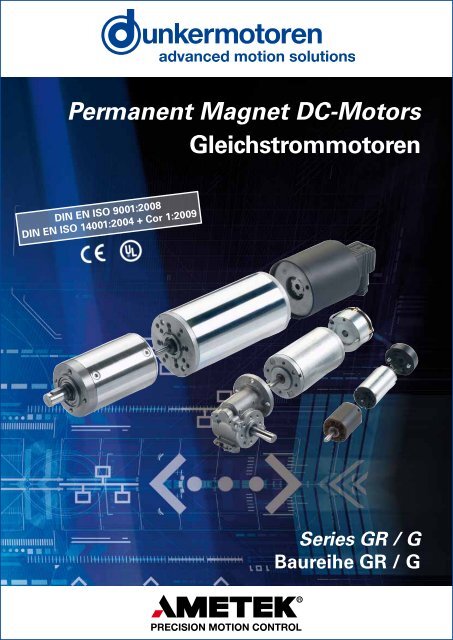
Permanent Magnet DC-Motors<strong>Gleichstrommotoren</strong>DIN EN ISO 9001:2008DIN EN ISO 14001:2004 + Cor 1:2009Series <strong>GR</strong> / G<strong>Baureihe</strong> <strong>GR</strong> / G
Foreword / VorwortContent / InhaltTo Our Valued Customers,<strong>Dunkermotoren</strong> is a world class leader in high qualitymotion control solutions to meet the ever increasingdemands for cost effective and reliable drive solutions.Our comprehensive product range offers the flexibilityto provide customized solutions as well as standardizedcomponents.The catalog represents <strong>Dunkermotoren</strong>´s years ofengineering excellence.The <strong>Dunkermotoren</strong> Team will continue to utilize ouroutstanding engineering and industrial capabilities to meetthe requirements helping you to succeed.Wishing you great success in your business.Nikolaus GräfGeneral ManagerLiebe Kunden,als führender Hersteller der Antriebstechnik bieten wirIhnen wirtschaftliche, effiziente und qualitativ hochwertigeKomplettlösungen.Unser umfassendes Produkt- und Leistungsspektrumermöglicht Ihnen ein hohes Maß an Flexibilität: Obstandardisierte Komponenten oder kundenspezifischeAnforderungen – bei uns finden Sie garantiert diepassende Lösung.Mit diesem Katalog können Sie sich einen Überblicküber unsere innovativen und richtungsweisenden Produkteverschaffen.Das <strong>Dunkermotoren</strong>-Team berät Sie gerne engagiert undkompetent. Denn: Ihr Erfolg ist unser Ziel.In diesem Sinne freuen wir uns auf Sie und wünschenIhnen alles Gute.Ihr Nikolaus GräfGeneral Manager2 Foreword / Vorwort3 Content / Inhalt4 Why <strong>Dunkermotoren</strong>? / Gute Gründe6 Our Product Range / Unser modulares Lieferprogramm7 Applications / Anwendungen8 DC Motors <strong>GR</strong>/G / <strong>Kollektor</strong>-<strong>Gleichstrommotoren</strong> <strong>GR</strong>/G9 <strong>GR</strong>/G Selection Guide / <strong>GR</strong>/G-Auswahlübersicht10 Technical Information / Technische Informationen11 Engineering Reference / Auslegung des Antriebs12 <strong>GR</strong> 23 22 2,5 4 W14 G 30.2 4 W16 G 30.1 6 W16 G 30.1 S 7 W18 G 30.0 10 W18 G 30.0 S 11 W20 <strong>GR</strong> 42x25 15 W22 <strong>GR</strong> 42x40 20 W24 <strong>GR</strong> 51x30 40 W26 <strong>GR</strong> 51x58 60 W28 <strong>GR</strong> 53x30 40 W30 <strong>GR</strong> 53x58 60 W32 <strong>GR</strong> 53 SI 40 W32 <strong>GR</strong> 53 SI 60 W34 <strong>GR</strong> 63x25 50 W36 <strong>GR</strong> 63x55 100 W38 <strong>GR</strong> 63S 130 W40 <strong>GR</strong> 63 SI 50 W40 <strong>GR</strong> 63 SI 100 W42 <strong>GR</strong> 80x40 120 W44 <strong>GR</strong> 80x80 240 W47 Gears / Getriebe48 PLG72 SG80 Brakes for <strong>GR</strong>/G Motors / Bremsen für <strong>GR</strong>/G-Motoren82 Tacho generators / Tachogeneratoren83 Magnetic pulse generator / Magnetische Impulsgeber84 Incremental Encoders for <strong>GR</strong>/G Motors / Inkrementalgeber für <strong>GR</strong>/G-Motoren86 Controller / Regelelektroniken92 Accessories / Zubehör94 Representatives and Distributors / Vertretungen© 10/2012<strong>Dunkermotoren</strong> GmbH2Printed in Germany3
Why <strong>Dunkermotoren</strong>? / Gute GründeTechnology & Customer FocusInnovation und KundenorientierungService & ProximityService & KundennäheAt <strong>Dunkermotoren</strong>, research and developmentis a way of life. The company is activelycommitted to develop key technologies andproducts that are crucial for its growth. Nextgenerationtechnology is in the R&D pipelinetoday.Product development is focused on innovationsto help our customers create value anddifferentiate themselves from competitors.<strong>Dunkermotoren</strong> ist stolz darauf, vielfach neueIndustrie-Standards in der Antriebsbranchegeschaffen zu haben. Es ist der Ansprucheines Technologieführers, der Konkurrenzimmer einen entscheidenden Schritt vorauszu sein.Unsere innovativen marktorientiertenAntriebslösungen machen unsere Kundennoch erfolgreicher und helfen ihnen, sichmit ihren Produkten positiv von denen derMitbewerber abzusetzen.Whether home or abroad, <strong>Dunkermotoren</strong>´smulti-lingual customer service advisers arealways on hand. By worldwide local presenceof <strong>Dunkermotoren</strong> individual responsibility isgiven to the interests of the trading partners- the best drive solution and the most economicalapplication.Today and in the future, <strong>Dunkermotoren</strong> willprovide a total service to the customers -wherever they are.Ob im In- oder Ausland, die Kundenberatervon <strong>Dunkermotoren</strong> sind immer vor Ortpräsent und sprechen die Sprache desKunden.Zur bestmöglichen Berücksichtigung derInteressen des Kunden werden individuelleSchulungen, Betreuung und Beratung durchunsere hochkompetenten Account Managergewährleistet.In der Technik wie auch im Vertrieb - dieMitarbeiter von <strong>Dunkermotoren</strong> scheuenkeine Herausforderung, Ihre Anforderungenund Wünsche sind Maßstab für Denken undHandeln.Quality Assurance & ReliabilityOne of <strong>Dunkermotoren</strong>´s primary objectivesis to offer outstanding quality.In 1991 <strong>Dunkermotoren</strong> became the world´sfirst manufacturers of small motors to becertified to ISO 9001. In the meantime,<strong>Dunkermotoren</strong> has won numerous qualityawards.<strong>Dunkermotoren</strong> regards quality as a comprehensiveprocess involving all activities in thefactory. Our products are manufactured inGermany and China on highly automatedproduction lines. Failure mode and effectsanalysis during design and development,and fully automated testing integrated in theproduction line ensure a uniformly high levelof quality.Qualität & ZuverlässigkeitAntriebslösungen höchster Qualität sind bei<strong>Dunkermotoren</strong> eine Selbstverständlichkeit,fest verankert in Unternehmensgrundsätzenund Philosophie. Bereits 1991 wurde <strong>Dunkermotoren</strong>als weltweit erster Hersteller vonKleinmotoren nach ISO 9001 zertifiziert. Inder Zwischenzeit folgten zahlreiche weitereAuszeichnungen und Zertifizierungen vonKunden und Vereinigungen.<strong>Dunkermotoren</strong> versteht Qualität als einenganzheitlichen Prozess, der sämtliche betrieblicheTätigkeiten umfasst.<strong>Dunkermotoren</strong> produziert in Deutschland undChina; hochautomatisierte Fertigungsstreckenund vollautomatische Qualitätskontrollen inden Fertigungslinien gewährleisten einkonstant hohes Qualitätsniveau.Sustainable Development<strong>Dunkermotoren</strong> is fully aware of its role topromote sustainable development. Thereforeit commits itself to pay particular attention tothe environment conservation while selectingand using efficiently raw materials and energynecessary for production, supply and use ofthe product.In 2002 <strong>Dunkermotoren</strong> has introduced theenvironmental management systemconforming to the standard ISO 14001.Umweltschutz und nachhaltigeEntwicklung<strong>Dunkermotoren</strong> ist sich seiner Rolle,nachhaltige Entwicklung zu fördern,bewusst. Deshalb hat sich die Firma demUmweltschutz verpflichtet. Ressourcenwerden sparsam und effizient eingesetzt.Als erster Hersteller von Elektrokleinmotorenerhielt <strong>Dunkermotoren</strong> im Jahre 2002 dieUmweltmanagementauszeichnung nachDIN EN ISO 14001.Flexibility, Delivery Performance &Complete Motion SolutionsStandardized motors, gears and modularaccessories are available with a higher degreeof flexibility to address specific requirementsin complete motion solutions. For thecustomer, this means better control of quality,reduced inventory and reduced productiontime. If any detail does not entirely meet yourrequirements, our R&D department will makemodifications at short notice.Flexibilität, Lieferperformance undumfassende AntriebslösungenDie Produktpalette von <strong>Dunkermotoren</strong> istso aufgebaut, dass sich mit standardisiertenMotoren und einem modular aufgebautenZubehör eine hohe Flexibilität für umfassendeAntriebslösungen ergibt. Und sollten Sieeinmal ein Produkt benötigen, das es nochnicht gibt, dann entwickelt unsereKonstruktionsabteilung kundenspezifischeSonderlösungen in kürzester Zeit.Therefore / Darum<strong>Dunkermotoren</strong>’s Modular System anoptimized logistics, enables prompt deliveryfor both stock and customized products.Delivery time for stock items is 2-5 days andfor customized solutions is 3-7 weeks.Aufgrund der konsequenten Verwirklichungdes Baukastensystems und einer ausgeklügeltenProduktionslogistik bietet <strong>Dunkermotoren</strong>eine bessere Lieferperformance alsdie meisten Mitbewerber, bei Lagerprodukten(Ø 2-5 Tage) wie auch bei kundenspezifischenLösungen (Ø 3-7 Wochen).45
Our Product Range / Unser modulares LieferprogrammApplications / AnwendungenDC-Motors<strong>Gleichstrommotoren</strong>Brushless DC Motors, Series BGBürstenlose <strong>Gleichstrommotoren</strong>, <strong>Baureihe</strong> B<strong>GR</strong>ated voltage 12-360 VDC Nennspannung 12-360 VDCRated speed 2300-4050 rpm Nenndrehzahl 2300-4050 min -1Torque 2.6-150 Ncm Drehmoment 2,6-150 NcmPower rating 10-530 W Abgabeleistung 10-530 WDC Motors, Series <strong>GR</strong>/G<strong>Gleichstrommotoren</strong>, <strong>Baureihe</strong> <strong>GR</strong>/<strong>GR</strong>ated voltage 3-220 VDC Nennspannung 3-220 VDCRated speed 1500-10000 rpm Nenndrehzahl 1500-10000 min -1Torque 0.47-65 Ncm Drehmoment 0,47-65 NcmPower rating 3-240 W Abgabeleistung 3-240 WSome ApplicationsIndustrial Automationwood machineryprinting industrypaper industrytextile industryfood & beverage machinerypackaging machinerysemiconductor industryplastics industrymaterial handlingmechanical handlingMedical devices & laboratory equipmentDoor automationSun protectionMotiveBeispiele für AnwendungenIndustrielle AutomatisierungHolzbearbeitungDruckindustriePapierindustrieTextilmaschinenLebensmittelmaschinenVerpackungsmaschinenHalbleiterindustrieKunststoffherstellungMaterialhandlingLager und FördertechnikMedizin- und LabortechnikTürautomationSonnenschutzMotiveAC-MotorsWechselstrommotorenAC Motors, Series KD/DRDreh- u. Wechselstrommotoren, <strong>Baureihe</strong> KD/DRRated voltage 230-400 VAC, 50Hz Nennspannung 230-400 VAC, 50HzPower rating 5-86 W Abgabeleistung 5-86 WTorque 3.6-31.5 Ncm Drehmoment 3,6-31,5 NcmVariants 2/4 pole Varianten 2/4 poligVenetian Blind- and Positioning Drives, Series D Jalousie- und Stellantriebe, <strong>Baureihe</strong> DRated voltage 230 VAC, 50 Hz Nennspannung 230 VAC, 50 HzRated speed 11-52 rpm Nenndrehzahl 11-52 min -1Torque 3-20 Nm Drehmoment 3-20 NmPower rating 50-220 W Abgabeleistung 50-220 WAccessoriesAnbautenPlanetary Gearboxes, Series PLGPlanetengetriebe, <strong>Baureihe</strong> PLGContinuous torque 0.3-160 Nm Dauerdrehmoment 0,3-160 NmRatio 4:1-710:1 Untersetzungsverhältnis 4:1-710:1Worm Gearboxes, Series SGSchneckengetriebe, <strong>Baureihe</strong> SGContinuous torque 1-30 Nm Dauerdrehmoment 1-30 NmRatio 5:1-80:1 Untersetzungsverhältnis 5:1-80:1Brakes, Series EEncoders, Series RE/TG/MEElectronic Control Systems, Series BGE/RSBremsen, <strong>Baureihe</strong> EInkrementalgeber, <strong>Baureihe</strong> RE/TG/MERegelelektroniken, <strong>Baureihe</strong> BGE/RSCustomized SolutionsThe impossible takes a little longer - customer specificsolutions from <strong>Dunkermotoren</strong>!Take advantage of the full range of knowledge and experienceof our drive specialists.We will develop the best possible drive unit solution for you- innovative, objective and application-oriented.Kundenspezifische LösungenGeht nicht gibt´s nicht - Kundenspezifische Lösungenvon <strong>Dunkermotoren</strong>!Profitieren Sie vom Know-how des Antriebsspezialisten.Wir realisieren zielgerichtet, innovativ und anwendungsorientiertdie bestmögliche Antriebseinheit für Sie.67
Permanent Magnet DC-Motors <strong>GR</strong>/G<strong>Gleichstrommotoren</strong> <strong>GR</strong>/GDIN EN ISO 9001:2008DIN EN ISO 14001:2004<strong>GR</strong>/G Selection Guide<strong>GR</strong>/G-AuswahlmöglichkeitenThe <strong>Dunkermotoren</strong> <strong>GR</strong>/G range (commutatedDC-motors) are notable for:• Longer life than commutated motors from othermanufacturers• Low detent torques• High efficiency• High dynamic acceleration• Good regulation characteristics• High power density• Maintenance-free• Robust design• Low moment of inertia• Motor insulation class E• Extremely high short time overload capacityof the motor• Surface protection• Minimum interference radiation, optionalinterference versions• Protection up to IP 67 (<strong>GR</strong> 42, <strong>GR</strong> 53, <strong>GR</strong> 63, <strong>GR</strong> 80)• High quality due to fully automated production linesThe DC-motors can be combined with control electronics,gearboxes, brakes and encoders in a modular system toprovide a flexible, adaptable, market-oriented solution.You will find further technical information, layout data, andinformation on the selection of motors and gearboxes onpage 10, and on the internet at:www.dunkermotoren.com<strong>Dunkermotoren</strong> der <strong>Baureihe</strong>n <strong>GR</strong>/G (<strong>Kollektor</strong>-<strong>Gleichstrommotoren</strong>) zeichnen sich aus durch:• Höhere Lebensdauer als <strong>Kollektor</strong>motoren andererHersteller• Geringe Rastmomente• Hoher Wirkungsgrad• Dynamische Beschleunigung• Gute Regelbarkeit• Hohe Leistungsdichte• Wartungsfreiheit• Robuster Aufbau• Geringes Trägheitsmoment• Motor nach Isolierstoffklasse E• Extrem hohe Kurzzeitüberlastfähigkeit des Motors• Oberflächenschutz• Minimale Störstrahlaussendung, optionalEntstörvarianten• Schutzart bis zu IP 67 (<strong>GR</strong> 42, <strong>GR</strong> 53, <strong>GR</strong> 63, <strong>GR</strong> 80)• höchste Qualität aufgrund vollautomatisierterFertigungsstreckenDie <strong>Gleichstrommotoren</strong> ergeben im Baukastensystemzusammen mit Regelelektroniken, Getrieben, Bremsenund Istwertgebern ein flexibles, anpassungsfähiges undmarktorientiertes Sortiment.Weitere technische Informationen, Auslegungen undInformationen zur richtigen Auswahl von Motoren undGetrieben erhalten Sie auf S. 10 in diesem Katalog und imInternet beiwww.dunkermotoren.de2,5 4.3 W1.0 0,47 Ncm4 W1 Ncm6 W1.7 Ncm7 W2 Ncm10 W3 Ncm11 W3.7 Ncm15 W4 Ncm20 W5.7 NcmPage/Seite 12 14 16 16 18 18 20 22 24 26 28 30 34 36 38 42 44GEARBOXES / GETRIEBEPLG 24 (0.3 - 0.6 Nm) 48PLG 30 (0.3 - 1.8 Nm) 50PLG 30 H (0.3 - 1.8 Nm) 52PLG 32 (0.4 - 4 Nm) 54PLG 32 H (0.4 - 4 Nm) 56PLG 42 K (0.7 - 3 Nm) 58PLG 42 S (3.5 - 14 Nm) 60PLG 52 (1.2 - 24 Nm) 62PLG 52 H (1.2 - 24 Nm) 64PLG 60 (5 - 25 Nm) 66PLG 63 (15 - 100 Nm) 68PLG 75 (25 - 160 Nm) 70SG 45 (0.25 - 0.75 Nm) 72SG 62 (1 - 1.5 Nm) 74SG 80 (2 - 10 Nm) 76SG 120 (8 - 30 Nm) 78BRAKES / BREMSENE 38 R 80E 46 A 80E 90 R 80E 100 R 80E 100 A 80TACHO GENERATORS / TACHOGENERATORENTG 11 82TG 52 82MAGNETIC PULSE GENERATOR / MAGNETISCHE IMPULSGEBERMG 2 83ME 52 83ME 80 83INCREMENTAL ENCODERS / INKREMENTALGEBERRE 20 84RE 30 84RE 56 84ELECTRONIC CONTROL SYSTEMS / REGEL-ELEKTRONIKENSI (4Q)Integral Servo ControllerServoregler integriert32/40RS 200 86BGE 3508 / 6005* 88BGE 3515 / 6010* 9022<strong>GR</strong> 23G 30.2G 30.1ACCESSORIES / ZUBEHÖR40 W10 Ncm60W17 Ncm40 W10 NcmMiscellaneous 92Verschiedenes* For G/ <strong>GR</strong> motors with incremental encoder RE 30 attached * Für Motoren mit angebautem Inkrementalgeber RE 30n Standard / Standard n On request / auf AnfrageG 30.1 SG 30.0G 30.0 S<strong>GR</strong> 42x25<strong>GR</strong> 42x40<strong>GR</strong> 51x30<strong>GR</strong> 51x58<strong>GR</strong> 53X3060 W17 Ncm<strong>GR</strong> 53X5850 W15 Ncm<strong>GR</strong> 63X25100 W28 Ncm<strong>GR</strong> 63X55130 W37 Ncm<strong>GR</strong> 63SX55120 W35 Ncm<strong>GR</strong> 80X40240 W63 Ncm<strong>GR</strong> 80X8089
Technical Information / Technische InformationEngineering Reference / Auslegung des AntriebsPERFORMANCE DATALEISTUNGSDATENMOTOR CHARACTERISTIC DIA<strong>GR</strong>AMSMOTORDIA<strong>GR</strong>AMMEPerformance figures given in the tables are measured in accordancewith EN60034. These figures are based on the assumption that themotor is freestanding and that certain other theoretical conditions arefulfilled. In a real application the rated torque of a motor will often beconsiderably higher, since by assembly conditions and circulation ahigher heat dissipation is achieved.For many applications, it is sufficiently accurate to take the mostimportant data from the motorcharacteristic diagramsand data tables. Althoughtolerances and temperatureinfluences are not taken intoaccount, the data is accurateenough for approximatecalculations. The degree ofprotection quoted relatesonly to the housing –adequate sealing of the shaftis the responsibility of thecustomer.current/Strom I (A)2.82.421.61.20.80.40efficiency/Wirkungsgrad η (%)706050403020100rated speed/Drehzahl n (rpm)700060005000 N = f (M)400030002000ηContinuous operationDauerbetriebIn den Datentabellen sind die Werte gemessen nach EN60034 angegeben.Diese Werte basieren auf der Annahme eines freistehendenMotors und auf weiteren theoretischen Gegebenheiten. Im reellenEinsatzfall liegt das Nenndrehmoment des Motors oftmals wesentlichhöher, da durch Einbaubedingungen und Zirkulation eine höhereWärmeabfuhr erzielt wird.Den Motordiagrammen und Datentabellen können die für viele Anwendungenwichtigsten Daten entnommenwerden. Obwohl Toleranzen undCyclic operationZyklischer BetriebDestroying operationZerstörende BetriebszuständeJ = f (M)10000M N-0.8 0 0.8 1.6 2.4 3.2 4 4.8 5.6 6.4 7.2 8 NcmTemperatureinflüsse nicht berücksichtigtsind, reichen die Werte fürüberschlagsmässige Betrachtungenaus. Die angegebenen Schutzartenbeziehen sich nur auf die Gehäuse.Die Abdichtung der Welle ist vomKunden vorzunehmen.- Speed curve (blue)This curve shows the speed characteristic at constant voltage. Its endpoints are the no-load speed n 0(1) and the theoretical starting torqueM A(2).- Current curve (black)The current curve shows the relationship between current and torque.Its end points are the no-load current I 0(3) and the starting current I A(4).- Efficiency curve (green)The efficiency is the relationship between the mechanical power outputand the electrical power input.The curve shows the efficiency with the motor in cold condition; as themotor warms up, the curve shifts accordingly.- Rated torque M N, Starting torque M maxThe rated torque (red) is the limit of the continuous operation region(shaded blue). In the region between the rated torque and the maximumpermissible torque, the motor must only be used intermittently (shadedorange). Operating conditions above the maximum permissible torqueresult in demagnetization of the permanent magnets (shaded red).ENGINEERING REFERENCE- Drehzahlkennlinie (blau)Diese Kennlinie beschreibt das Drehzahlverhalten bei konstanter Spannung.Deren Endpunkte zeigen die Leerlaufdrehzahl n 0(1) und dastheoretische Anlaufmoment M A(2).- Stromkennlinie (schwarz)Die Stromkennlinie stellt die Äquivalenz von Strom und Drehmomentdar. Deren Endpunkte zeigen den Leerlaufstrom I 0(3) und den AnlaufstromI A(4).- Wirkungsgradkennlinie (grün)Der Wirkungsgrad beschreibt das Verhältnis von abgegebenermechanischer Leistung zu aufgenommener elektrischer Leistung.Die Kennlinien beziehen sich auf den Kaltzustand des Motors und verschiebensich entsprechend bei zunehmender Erwärmung des Motors.- Nenndrehmoment M N, Anlaufdrehmoment M maxDas Kriterium Nenndrehmoment (rot) begrenzt den Dauerbetriebsbereich(blau schattiert). Im Bereich zwischen Nenndrehmoment undmax. zulässigem Drehmoment darf der Motor nur kurzzeitig betriebenwerden (orange schattiert). Betriebszustände über dem max. zulässigenDrehmoment führen zur Entmagnetisierung der Dauermagneten (rotschattiert).AUSLEGUNG DES ANTRIEBS- Nominal voltage U N(VDC)The DC voltage that is applied to the motor as a supply voltage. Allrated data in our catalogs are with reference to this voltage. Motorapplications are, however, not restricted to this voltage.- Nominal torque M N(Ncm)The torque that can be produced by the motor, operatingcontinuously, in an ambient temperature of 20°C.- Rated speed n N(min -1 )The speed of the motor when it is operating at rated torque (5).- Rated current I N(A)The current drawn from a DC source when the motor is operating atrated torque (6).- Starting current I A(A)The current required to produce the starting torque. For motors withelectronics, the starting current may be higher than the permissiblepeak current (4).- Starting torque M A(Ncm)The maximum torque the motor can produce (2).- Rated power P N(W)The output power which the motor can produce continuously; it iscalculated from rated speed and rated torque.- Rotor inertia J R(gcm 2 )The moment of inertia of the rotor is the factor that determines thedynamic properties of a motor.- Max. permissible voltage range U max(VDC)The minimum and maximum permissible input voltage for electronicsor motors with integral electronics.- Recommended speed control range n max(min -1 )The regulated speed range within which rotor position sensing byHall sensors ensures a smooth torque curve. As a rule, this rangecan be extended by installing a rotary encoder.- Nennspannung U N(VDC)Die Gleichspannung, die als Versorgungsspannung an den Motorangelegt wird. Auf diese Spannung beziehen sich alle Nenndaten inden Katalogen. Die Motoranwendung ist jedoch nicht auf dieseSpannung beschränkt.- Nennmoment M N(Ncm)Das Moment, das der Motor bei einer Umgebungstemperaturvon 20°C im Dauerbetrieb abgeben kann.- Nenndrehzahl n N(min -1 )Die Drehzahl, die sich bei Abgabe des Nenndrehmoments einstellt (5).- Nennstrom I N(A)Der Strom, der der Gleichspannungsquelle entnommen wird, wennder Motor bei Nenndrehmoment betrieben wird (6).- Anlaufstrom I A(A)Der Strom, der fließt, um das Anlaufmoment zu erzeugen. BeiMotoren mit Elektronik kann der Anlaufstrom höher sein als derzulässige Spitzenstrom (4).- Anlaufmoment M A(Ncm)Das Moment, welches der Motor maximal erzeugen kann (2).- Nennleistung P N(W)Die Abgabeleistung des Motors, welche er dauerhaft erzeugen kann;berechnet aus Nenndrehzahl und Nenndrehmoment.- Rotor Trägheitsmoment J R(gcm 2 )Massenträgheitsmoment des Rotors und bestimmende Größe für diedynamischen Eigenschaften des Motors.- Max. zulässiger Spannungsbereich U max(VDC)Die minimal und maximal zulässige Eingangsspannung beiElektroniken oder Motoren mit integrierter Elektronik.- Empfohlener Drehzahlregelbereich n max(min -1 )Der Drehzahlregelbereich in dem bei Rotorlageerkennung durchHallsensoren ein glatter Drehmomentverlauf steuerbar ist. DurchAnbringung eines Inkrementalencoders kann dieser Bereich in derRegel erweitert werden.In the wide range of <strong>Dunkermotoren</strong> products, you will find a suitabledrive for almost any requirement in powers ranging from 1 - 530 Watt.Please also note our other product lines and catalogs (Brushless DCMotors, AC motors).The following points should be taken into account when selectingmotors and gearboxes:- Which type of operation is required (continuous, intermittentor periodic operation)?- What is the working life expected of the motor?- What torque and speeds are required?- How much space is available for the motor?- How high is the available voltage? DC or AC?- Are there special environmental conditions (temperature,humidity, vibration, ...)?- To what degree can heat from the motor be disposed of?- Are there exceptional axial and radial shaft loads to consider?- What demands are made of the motor control electronics?- Is the motor to be controlled online via a bus system?- Do you need a brake, an encoder or a non-reversing device?By dimensioning a suitable motor, determining the required torque playsa decisive role in avoiding thermal overload of the motor in service. Inthe assembly of a drive system consisting of motor and control electronics,it is important to ensure that permissible values for the motorare not exceeded by outputs from the electronics.Depending on the speed of rotation required, a motor or a motorgearboxcombination may be selected. The choice of a reductiongearbox will largely depend on the recommended maximum torquein continuous operation. For intermittent duty, loading above the ratedtorque is possible.When choosing a motor after deciding on the gearbox, the followingapplies:M motor= M gearbox/ (i x h)We will be pleased to carry out a precise adaptation of a motor to yourservice conditions.M max11In <strong>Dunkermotoren</strong>´s breiter Produktpalette finden Sie für nahezu jedeAnforderung einen passenden Antrieb im Leistungsbereich von1 - 530 Watt. Bitte beachten Sie auch unsere weiteren Produktlinien und-kataloge (Bürstenlose DC-Elektronikmotoren, Wechselstromotoren).Folgende Punkte sollten bei der Auswahl von Motor und Getriebeberücksichtigt werden:- Welche Betriebsart liegt vor (Dauer-, Kurzzeit- oder Aussetzbetrieb)?- Welche Lebensdauer wird gefordert?- Welches Drehmoment und welche Drehzahl werden benötigt?- Wie viel Raum ist für den Motor verfügbar?- Wie hoch ist die verfügbare Spannung? Gleich- oderWechselspannung?- Gibt es besondere Umgebungseinflüsse (Temperatur,Feuchtigkeit, Vibration, ...)?- In welchem Umfang wird die Motorwärme abgeleitet?- Müssen außergewöhnliche axiale und radiale Wellenbelastungenberücksichtigt werden?- Welchen Steuerungsanforderungen muss die Steuerungselektronikdes Motors genügen?- Werden die Motoren online über ein Bussystem angesteuert?- Benötigen Sie eine Bremse, einen Encoder oder eineRücklaufsperre?Für die Auslegung des geeigneten Motors spielt die Ermittlung deseffektiven Drehmomentes die entscheidende Rolle, um zu verhindern,dass der Motor im Betrieb thermisch überlastet wird. Für die Zusammenstellungeines Antriebssystems aus Motor und Betriebselektronikist zu berücksichtigen, dass die für den Motor zulässigen Werte durchdie Elektronik nicht überschritten werden.Je nach gewünschter Drehzahl wird man sich entweder für einen Motoroder einen Getriebemotor entscheiden. Die Wahl des Untersetzungsgetriebesrichtet sich nach dem empfohlenen maximalen Drehmomentbei Dauerbetrieb. Bei kurzzeitigem Betrieb sind auch Belastungen überdem Nennmoment möglich.Zur Auswahl des Motors nach Festlegung des Getriebes gilt:M Motor= M Getriebe/ (i x h)Gerne erfolgt auf Anfrage eine exakte Anpassung des Motors an IhreBetriebsbedingungen.The data in this catalog contain product specifications, but are not aguarantee of particular properties. The stated values are subject totolerances. Any supplementary information and safety instructions givenin the operating manual must be observed with no exceptions.Die Angaben in diesem Katalog enthalten Spezifikationen der Produkte,nicht aber die Zusicherung von Eigenschaften. Die genannten Werteunterliegen Toleranzen. Die im Betriebshandbuch angegebenenErgänzungen und Sicherheitshinweise sind unbedingt zu beachten.We reserve the right to make technical changes and to restrictavailability.Liefermöglichkeiten und technische Änderungen vorbehalten.10
<strong>GR</strong> 22 / <strong>GR</strong> 22 S, 2.5 W / 3 W<strong>GR</strong> 22 / <strong>GR</strong> 22 S, 2.5 W / 3 WVersions of <strong>GR</strong> 22, <strong>GR</strong> 22 S / Ausführungen <strong>GR</strong> , <strong>GR</strong> SWith gearbox / Als Getriebemotor 45With magnetic pulse generator / Mit magnetischem Impulsgeber 61n Standard / Standard n On request / auf Anfrage• General information about the characteristics of ourcommutated motors, see page 8• With flat connection as standard• Special windings available on request• Different shaft lengths as per our program available on request• Motor shaft with slide bearing• Please note that the minimum order quantity for this motoris 100 piecesPage / Seite• Allgemeine Informationen über die Eigenschaften unserer<strong>Kollektor</strong>motoren siehe S. 8• Der Motor wird standardmäßig mit Flachstecker geliefert• Sonderwicklungen auf Anfrage erhältlich• Auf Anfrage verschiedene Wellenlängen gemäß unseremProgramm lieferbar• Die Motorwelle ist bei diesem Motor gleitgelagert• Beachten Sie, dass dieser Motor für Bedarfsfälle ab 100 Stücklieferbar istDimensions in mm / Maßzeichnung in mm15°60°10°10°15°13.2 ±0.11.8 ±0.05120°Depth/M 2. 4 TiefeØ 10 -0.08Flat Connector/Flachstecker A2.8x0.5 DIN 462447 ±0.51.5 ±0.1Ø 22 ±0.1A1.5 ±0.1-0.002Ø 2 -0.008Ø 10 -0.050.030.07 A18 -145°16 ±0.192°1.8 ±0.0543.5 ±0.512 ±0.517 ±0.1Shaft / Wellefront / vorne back / hinten2 x 12 mm -2 x 12 mm 2 x 13.5 mmCharacteristic diagram / BelastungskennlinienIn accordance with EN 60034Belastungskennlinien gezeichnet nach EN 600342.82.470601400012000ϑ R =20°C∅ϑ W = 100K2.82.470601400012000ηϑ R =20°C1Data / Technische Daten <strong>GR</strong> 22Rated voltage/Nennspannung VDC 6 12 24Continuous rated speed/Nenndrehzahl rpm*) 4000 5000 4600Continuous rated torque/Nenndrehmoment Ncm*) 0.46 0.47 0.48Continuous current/Nennstrom A*) 0.83 0.47 0.23Starting torque/Anlaufmoment Ncm**) 1.09 1.4 1.4Starting current/Anlaufstrom A**) 1.6 1.14 0.54No load speed/Leerlaufdrehzahl rpm**) 7800 8700 8100No load current/Leerlaufstrom A**) 0.22 0.14 0.07Rotor inertia/Trägheitsmoment gcm 2 2.4 2.4 2.4Weight of motor/Motorgewicht g 50 50 50Data / Technische Daten<strong>GR</strong> 22 SRated voltage/Nennspannung VDC 6 12 24Continuous rated speed/Nenndrehzahl rpm*) 3500 4600 4100Continuous rated torque/Nenndrehmoment Ncm*) 0.55 0.55 0.57Continuous current/Nennstrom A*) 0.83 0.47 0.23Starting torque/Anlaufmoment Ncm**) 1.31 1.6 1.57Starting current/Anlaufstrom A**) 1.60 1.14 0.53No load speed/Leerlaufdrehzahl rpm**) 7000 7600 7300No load current/Leerlaufstrom A**) 0.32 0.16 0.08Rotor inertia/Trägheitsmoment gcm 2 2.4 2.4 2.4Weight of motor/Motorgewicht g 50 50 50*) DJ w= 100 K; **) J R= 20°Ccurrent/Strom I (A)current/Strom I (A)current/Strom I (A)21.61.20.80.401.41.210.80.60.40.200.70.60.50.40.30.20.10efficiency/Wirkungsgrad η (%)efficiency/Wirkungsgrad η (%)efficiency/Wirkungsgrad η (%)5040302010070605040302010070605040302010010000 N = f (M)rated speed/Drehzahl n (rpm)80006000400020001400012000ηJ = f (M)M0N-0.2 0 0.2 0.4 0.6 0.8 1 1.2 1.4 1.6 1.8 2Ncm10000 N = f (M)rated speed/Drehzahl n (rpm)1400012000N = f (M)10000rated speed/Drehzahl n (rpm)80006000400020000-0.2 0 0.2M N0.4 0.6 0.8 1 1.2 1.4 1.6 1.8 2Ncm800060004000<strong>GR</strong> 22, 6V<strong>GR</strong> 22, 12VηηJ = f (M)ϑ R =20°C∅ϑ W = 100Kϑ R =20°C∅ϑ W = 100KJ = f (M)20000-0.2 0 0.2M N0.4 0.6 0.8 1 1.2 1.4 1.6 1.8 2Ncm<strong>GR</strong> 22, 24Vcurrent/Strom I (A)current/Strom I (A)current/Strom I (A)2 50 100001.6 40N = f (M)8000J = f (M)1.20.80.401.41.210.80.60.40.200.70.60.50.40.30.20.10efficiency/Wirkungsgrad η (%)efficiency/Wirkungsgrad η (%)efficiency/Wirkungsgrad η (%)3020100706050403020100706050403020100rated speed/Drehzahl n (rpm)600040002000M0N-0.2 0 0.2 0.4 0.6 0.8 1 1.2 1.4 1.6 1.8 2Ncm14000ϑ R =20°C12000η10000N = f (M)J = f (M)8000rated speed/Drehzahl n (rpm)14000ϑ R =20°C1200010000ηN = f (M)J = f (M)8000rated speed/Drehzahl n (rpm)600040002000600040002000<strong>GR</strong> 22 S, 6VM0N-0.2 0 0.2 0.4 0.6 0.8 1 1.2 1.4 1.6 1.8 2Ncm<strong>GR</strong> 22 S, 12VM0N-0.2 0 0.2 0.4 0.6 0.8 1 1.2 1.4 1.6 1.8 2Ncm<strong>GR</strong> 22 S, 24V1
G 30.2, 4 WG 30.2, 4 WVersions of G 30.2 / Ausführungen G 30.2With gearbox / Als Getriebemotor 47With brake / Als Bremsmotor 80With tacho generator / Mit Tachogenerator 82With magnetic pulse generator / Mit magnetischem Impulsgeber 83With incremental encoder / Mit Inkrementalgeber 84n Standard / Standard n On request / auf AnfragePage / SeiteDimensions in mm / Maßzeichnung in mmFlat Connector/Flachstecker A 2.8x0.5 DIN 462440.050.12 A• General information about the characteristics of ourcommutated motors, see page 8• With flat connection as standard, lead versions are available• Different shaft lengths as per our program available on request• The standard version has a slide bearing motor shaft• Please note that the minimum order quantity for this motoris 100 pieces• Allgemeine Informationen über die Eigenschaften unserer<strong>Kollektor</strong>motoren siehe S. 8• Der Motor wird standardmäßig mit Flachstecker geliefert.Litzenversionen sind lieferbar• Auf Anfrage verschiedene Wellenlängen gemäß unseremProgramm lieferbar• In der Standardausführung ist die Motorwelle gleitgelagert• Beachten Sie, dass dieser Motor für Bedarfsfälle ab 100 Stücklieferbar ist45°M 3, 6 Depth/TiefeM 3,22 ±0.14 Depth/TiefeØ 129 ±0.5+0.4Ø 30 -0.22 +0.5 2 +0.5 14 ±0.540 ±0.5A0Ø 2.5 -0.008Ø12 +0.1-0.119.25+0.051.630°2.7 ±0.145°23.51616 ±0.1Shaft / Wellefront / vorne back / hinten2.5 x 14 mm -Characteristic diagram / BelastungskennlinienIn accordance with EN 60034Belastungskennlinien gezeichnet nach EN 600341.41.217060507000N = f (M)60005000ηJ = f (M)ϑ R =20°CW = 100K1.41.217060507000N = f (M)60005000ηϑ R =20°CW = 100K0.84040000.8404000J = f (M)14Data / Technische Daten <strong>GR</strong> 30.2Nominal voltage/Nennspannung VDC 12 24 40Nominal current/Nennstrom A *) 0.6 0.31 0.21Nominal torque/Nennmoment Ncm *) 1 1 1Nominal speed/Nenndrehzahl rpm *) 2900 3000 3500Friction torque/Reibungsmoment Ncm *) 0.25 0.25 0.3Peak stall torque/Max. Anhaltemoment Ncm **) 2.8 3 3.27No load speed/Leerlaufdrehzahl rpm *) 4900 5000 5400Maximum output power/Maximale Abgabeleistung W **) 3.44 4.06 4.62Torque constant/Drehmomentkonstante Ncm A -1***) 2.32 4.35 6.49Terminal Resistance/Anschlußwiderstand Ω 8.58 31.1 72.7Terminal inductance/Anschlußinduktivität mH 5.15 21.8 49.5Starting current/Anlaufstrom A **) 1.4 0.77 0.55No load current/Leerlaufstrom A **) 0.145 0.076 0.054Rotor inertia/Rotor Trägheitsmoment gcm 2 11 11.5 11Weight of motor/Motorgewicht kg 0.08 0.08 0.08*) DJ w= 100 K; **) J R= 20°C ***) at nominal point / im Nennpunktcurrent/Strom I (A)current/Strom I (A)0.60.40.200.70.60.50.40.30.20.10efficiency/Wirkungsgrad η (%)efficiency/Wirkungsgrad η (%)3020100706050403020100rated speed/Drehzahl n (rpm)rated speed/Drehzahl n (rpm)300020001000300020001000M0N-0.4 0 0.4 0.8 1.2 1.6 2 2.4 2.8 3.2 3.6 4NcmG 30.2, 12V7000ϑ R =20°C6000W = 100KJ = f (M)5000 N = f (M)η4000M0N-0.4 0 0.4 0.8 1.2 1.6 2 2.4 2.8 3.2 3.6 4NcmG 30.2, 40Vcurrent/Strom I (A)0.60.40.20efficiency/Wirkungsgrad η (%)3020100rated speed/Drehzahl n (rpm)300020001000M0N-0.4 0 0.4 0.8 1.2 1.6 2 2.4 2.8 3.2 3.6 4NcmG 30.2, 24V15
G 30.1 / G 30.1 S, 6 W / 7 WG 30.1 / G 30.1 S, 6 W / 7 WVersions of G 30.1, G 30.1 S / Ausführungen G 30.1, G 30.1 SWith gearbox / Als Getriebemotor 47With brake / Als Bremsmotor 80With tacho generator / Mit Tachogenerator 82With magnetic pulse generator / Mit magnetischem Impulsgeber 83With incremental encoder / Mit Inkrementalgeber 84n Standard / Standard n On request / auf AnfragePage / SeiteDimensions in mm / Maßzeichnung in mm45°M 3, 6 Depth/Tiefe9 ±0.5Flat Connector/Flachstecker A 2.8x0.5 DIN 46244A0Ø 2.5 -0.0080.050.12 A-0.119.25+0.051.645°• General information about the characteristics of ourcommutated motors, see page 8• With flat connection as standard, lead versions are available• Different shaft lengths as per our program available on request• The standard version has a slide bearing motor shaft• Please note that the minimum order quantity for this motoris 100 pieces• Allgemeine Informationen über die Eigenschaften unserer<strong>Kollektor</strong>motoren siehe S. 8• Der Motor wird standardmäßig mit Flachstecker geliefert.Litzenversionen sind lieferbar• Auf Anfrage verschiedene Wellenlängen gemäß unseremProgramm lieferbar• In der Standardausführung ist die Motorwelle gleitgelagert• Beachten Sie, dass dieser Motor für Bedarfsfälle ab 100 Stücklieferbar ist16 ±0.1M 3,22 ±0.14 Depth/TiefeØ 12+0.4Ø 30 -0.22 +0.5 2 +0.5 14 ±0.550 ±0.5Ø12 +0.130°2.7 ±0.123.516Shaft / Wellefront / vorne back / hinten2.5 x 14 mm -Characteristic diagram / BelastungskennlinienIn accordance with EN 60034Belastungskennlinien gezeichnet nach EN 600342.82.4270605070006000N = f (M)5000ηJ = f (M)ϑ R =20°CW = 100K2.82.42706050700060005000N = f (M)ηJ = f (M)ϑ R =20°C1.64040001.640400016Data / Technische Daten G 30.1 G 30.1 SNominal voltage/Nennspannung VDC 12 24 40 12 24 40Nominal current/Nennstrom A *) 0.9 0.45 0.28 0.90 0.45 0.28Nominal torque/Nennmoment Ncm *) 1.65 1.7 1.75 2.0 2.0 2.0Nominal speed/Nenndrehzahl rpm *) 3300 3400 3600 3050 3100 3250Friction torque/Reibungsmoment Ncm *) 0.35 0.35 0.35 0.35 0.35 0.35Peak stall torque/Max. Anhaltemoment Ncm **) 5.4 6.1 6.3 7.35 7.5 7.6No load speed/Leerlaufdrehzahl rpm *) 4650 4850 5100 4350 4400 4500Maximum output power/Maximale Abgabeleistung W **) 6.5 7.7 5.4 7.14 8.59 9.23Torque constant/Drehmomentkonstante Ncm A -1***) 2.32 4.52 9.04 2.80 5.59 8.7Terminal Resistance/Anschlußwiderstand Ω 4.9 17.1 67.4 4.61 15.68 40.0Terminal inductance/Anschlußinduktivität mH 3.64 15.35 60.8 3.68 14.1 30Starting current/Anlaufstrom A **) 2.4 1.4 0.93 2.60 1.53 0.95No load current/Leerlaufstrom A **) 0.18 0.09 0.06 0.20 0.11 0.08Rotor inertia/Rotor Trägheitsmoment gcm 2 18.5 18.5 18.5 18.5 19.5 18.5Weight of motor/Motorgewicht kg 0.11 0.11 0.11 0.11 0.11 0.11*) DJ w= 100 K; **) J R= 20°C ***) at nominal point / im Nennpunktcurrent/Strom I (A)current/Strom I (A)current/Strom I (A)1.20.80.402.82.421.61.20.80.401.41.210.80.60.40.20efficiency/Wirkungsgrad η (%)efficiency/Wirkungsgrad η (%)efficiency/Wirkungsgrad η (%)3020100706050403020100706050403020100rated speed/Drehzahl n (rpm)rated speed/Drehzahl n (rpm)rated speed/Drehzahl n (rpm)300020001000300020001000M0N-0.8 0 0.8 1.6 2.4 3.2 4 4.8 5.6 6.4 7.2 8Ncm70006000 N = f (M)5000η4000J = f (M)300020001000G 30.1, 12VM0N-0.8 0 0.8 1.6 2.4 3.2 4 4.8 5.6 6.4 7.2 8NcmG 30.1, 24VM0N-0.8 0 0.8 1.6 2.4 3.2 4 4.8 5.6 6.4 7.2 8Ncmcurrent/Strom I (A)1.20.80.40efficiency/Wirkungsgrad η (%)3020100rated speed/Drehzahl n (rpm)300020001000M0N0 0.8 1.6 2.4 3.2 4 4.8 5.6 6.4W = 100K 2.4 60 6000-0.8 7.2 8Ncmϑ R =20°C2.8 70 7000ϑ R =20°Cη2 50 5000 N = f (M)1.6 40 4000J = f (M)70001.4 70 7000ϑ R =20°Cϑ R =20°CN = f (M)6000W = 100K 1.2 60 6000ηη5000J = f (M)1 50 5000 N = f (M)J = f (M)40000.8 40 4000G 30.1, 40Vcurrent/Strom I (A)current/Strom I (A)1.20.80.400.60.40.20efficiency/Wirkungsgrad η (%)efficiency/Wirkungsgrad η (%)30201003020100rated speed/Drehzahl n (rpm)rated speed/Drehzahl n (rpm)300020001000300020001000G 30.1 S, 12VM0N-0.8 0 0.8 1.6 2.4 3.2 4 4.8 5.6 6.4 7.2 8NcmG 30.1 S, 24VM0N-0.8 0 0.8 1.6 2.4 3.2 4 4.8 5.6 6.4 7.2 8NcmG 30.1 S, 40V17
G 30.0 / G 30.0 S, 10 W / 11 WG 30.0 / G 30.0 S, 10 W / 11 WVersions of G 30.0, G 30.0 S / Ausführungen G 30.0, G 30.0 SWith gearbox / Als Getriebemotor 47With brake / Als Bremsmotor 80With tacho generator / Mit Tachogenerator 82With magnetic pulse generator / Mit magnetischem Impulsgeber 83With incremental encoder / Mit Inkrementalgeber 84Page / SeiteDimensions in mm / Maßzeichnung in mm45°9 ±0.5ca. 4.5Ø 3 g50.120.12AAØ 19.2523.5Ø 2.7±0.1n Standard / Standard n On request / auf AnfrageØ 12 -0.1+0.3Ø 30.6 -0.2Ø 5.7Ø 12-0.1Ø 16• General information about the characteristics of ourcommutated motors, see page 8• With flat connection as standard, lead versions are available• Special windings available on request• Different shaft lengths or shaft on both sides available asper our program• Ball bearing in the front side motor shaft. On request alsoavailable with ball bearing on both sides• Please note that the minimum order quantity for this motoris 100 pieces• Allgemeine Informationen über die Eigenschaften unserer<strong>Kollektor</strong>motoren siehe S. 8• Der Motor wird standardmäßig mit Flachstecker geliefert.Litzenversionen sind lieferbar• Sonderwicklungen auf Anfrage erhältlich• Auf Anfrage verschiedene Wellenlängen bzw. beidseitige Wellengemäß unserem Programm lieferbar• Die Motorwelle ist antriebsseitig kugelgelagert. Auf Anfrage auchmit beidseitiger Kugellagerung erhältlich• Beachten Sie, dass dieser Motor für Bedarfsfälle ab 100 Stücklieferbar ist4 x Ø 2.7 +0.1 Ø 16±0.14 x M3; 6.5Depth/TiefeØ 22±0.12 +0.575 ±0.575±052 +0.5 18±0.5F axial= max. 10NF radial= max. 22N15°45°+0.05Ø 1.6 -0.10Shaft / Wellefront / vorne back / hinten3 x 18 mm -3 x 10 mm -3 x 10 mm 3 x 15 mmCharacteristic diagram / BelastungskennlinienIn accordance with EN 60034Belastungskennlinien gezeichnet nach EN 6003476547060504070006000N = f (M)50004000ηJ = f (M)ϑ R =20°CW = 100K765470605040700060005000N = f (M)4000ηJ = f (M)ϑ R =20°C18Data / Technische Daten G 30.0 G 30.0 SNominal voltage/Nennspannung VDC 12 24 40 12 24 40Nominal current/Nennstrom A *) 1.4 0.71 0.4 1.40 0.71 0.40Nominal torque/Nennmoment Ncm *) 3 3 3 3.70 3.70 3.70Nominal speed/Nenndrehzahl rpm *) 2980 3030 2810 2500 2650 2600Friction torque/Reibungsmoment Ncm *) 0.5 0.5 0.45 0.5 0.5 0.5Peak stall torque/Max. Anhaltemoment Ncm **) 12.9 12.1 12.3 15.3 17 16.5No load speed/Leerlaufdrehzahl rpm *) 4130 4260 4100 3250 3550 3350Maximum output power/Maximale Abgabeleistung W **) 13.93 13.5 13.2 13.02 15.8 14.9Torque constant/Drehmomentkonstante Ncm A -1***) 2.88 4.97 8.73 3.36 6.36 11.02Terminal Resistance/Anschlußwiderstand Ω 2.61 9.4 27.4 2.55 8.73 26.4Terminal inductance/Anschlußinduktivität mH 2.61 8.5 24.7 2.61 7.42 24.7Starting current/Anlaufstrom A **) 4.6 2.5 1.46 4.7 2.75 1.52No load current/Leerlaufstrom A **) 0.25 0.13 0.07 0.25 0.14 0.08Rotor inertia/Rotor Trägheitsmoment gcm 2 42.2 42.2 42.2 42 42 42Weight of motor/Motorgewicht kg 0.24 0.24 0.24 0.24 0.24 0.24*) DJ w= 100 K; **) J R= 20°C ***) at nominal point / im Nennpunktcurrent/Strom I (A)current/Strom I (A)current/Strom I (A)32102.82.421.61.20.80.402.82.421.61.20.80.40efficiency/Wirkungsgrad η (%)efficiency/Wirkungsgrad η (%)efficiency/Wirkungsgrad η (%)3020100706050403020100706050403020100rated speed/Drehzahl n (rpm)rated speed/Drehzahl n (rpm)rated speed/Drehzahl n (rpm)3000200010006 8 10 12 14 16 18 20NcmM0NM0 0 0N-2 0 2 4 6 8 10 12 14 16 18 20 -2 0 2 4G 30.0, 12VNcmG 30.0 S, 12V6000J = f (M)W = 100K 2.4 60 60007000ϑ R =20°C2.8 70 7000ϑ R =20°CN = f (M)5000η2 50N = f (M)5000ηJ = f (M)40001.6 40 4000300020001000300020001000M0N-2 0 2 4 6 8 10 12 14 16 18 20NcmG 30.0, 24VM0N-2 0 2 4 6 8 10 12 14 16 18 20Ncmcurrent/Strom I (A)32170006000ϑ R =20°CW = 100K2.82.4706070006000ϑ R =20°C5000 N = f (M)η2 50 5000η4000J = f (M)1.6 40 4000 N = f (M)J = f (M)G 30.0, 40Vcurrent/Strom I (A)current/Strom I (A)1.20.80.401.20.80.40efficiency/Wirkungsgrad η (%)efficiency/Wirkungsgrad η (%)efficiency/Wirkungsgrad η (%)30201030201003020100rated speed/Drehzahl n (rpm)rated speed/Drehzahl n (rpm)rated speed/Drehzahl n (rpm)300020001000300020001000300020001000M0N-2 0 2 4 6 8 10 12 14 16 18 20NcmG 30.0 S, 24VM0N-2 0 2 4 6 8 10 12 14 16 18 20NcmG 30.0 S, 40V19
<strong>GR</strong> 42x25, 15 W<strong>GR</strong> 42x25, 15 WVersions of <strong>GR</strong> 42x25 / Ausführungen <strong>GR</strong> 42x25With gearbox / Als Getriebemotor 47With brake / Als Bremsmotor 80With controller / Mit Regelelektronik 86With tacho generator / Mit Tachogenerator 82With magnetic pulse generator / Mit magnetischem Impulsgeber 83With incremental encoder / Mit Inkrementalgeber 84n Standard / Standard n On request / auf AnfragePage / SeiteDimensions in mm / Maßzeichnung in mm45° ±1°M34 mal90° ±1°70±0.8 L2BAØ 5 g5Ø 90.060.03A90°2.75-0.1530°• General information about the characteristics ofour commutated motors, see page 8• The standard version has leads (300 mm)• Special windings available on request• Different shaft lengths or shaft on both sides available asper our program• Protection class IP 50, higher class available on request• Ball bearing in the motor shaft. For projects themotor is also available with slide bearing (G 42)• Allgemeine Informationen über die Eigenschaften unserer<strong>Kollektor</strong>motoren siehe S. 8• Der Motor wird standardmäßig mit Litzen (300 mm) geliefert• Sonderwicklungen auf Anfrage erhältlich• Auf Anfrage verschiedene Wellenlängen bzw. beidseitige Wellengemäß unserem Programm lieferbar• Schutzart IP 50, auf Anfrage auch höher• Die Motorwelle ist kugelgelagert. Projektbezogen ist der Motorauch mit Gleitlager erhältlich (G 42)6.5mmDepth/Tiefe22 -0.0532 ±0.10.2AØ 42 ±0.3black/schwarz-+red/rot 7 ±2300 ±30Leads/Litzen AWG 22 Tr 64 UL Style 15691 ±0.3220±122 -0.0532±0.127.5°0.2B20Data / Technische Daten<strong>GR</strong> 42x25Nominal voltage/Nennspannung VDC 12 24 40Nominal current/Nennstrom A *) 1.9 0.9 0.6Nominal torque/Nennmoment Ncm *) 3.9 3.8 3.9Nominal speed/Nenndrehzahl rpm *) 3450 3600 3700Friction torque/Reibungsmoment Ncm *) 0.7 0.7 0.7Peak stall torque/Max. Anhaltemoment Ncm **) 19 20 22No load speed/Leerlaufdrehzahl rpm *) 4350 4200 4400Maximum output power/Maximale Abgabeleistung W **) 21.6 22.1 25Torque constant/Drehmomentkonstante Ncm A -1***) 2.53 5.14 8.1Terminal Resistance/Anschlußwiderstand Ω 1.54 5.95 14.5Terminal inductance/Anschlußinduktivität mH 1.8 8.9 18.9Starting current/Anlaufstrom A **) 7.8 4 2.76No load current/Leerlaufstrom A **) 0.34 0.17 0.11Demagnetisation current/Entmagnetisierungsstrom A **) 14 6.5 4.1Rotor inertia/Rotor Trägheitsmoment gcm 2 71 71 71Weight of motor/Motorgewicht kg 0.39 0.39 0.39*) DJ w= 100 K; **) J R= 20°C ***) at nominal point / im Nennpunktcurrent/Strom I (A)(A)current/Strom I (A) current/Strom I (A)current/Strom I (A) current/Strom I (A)7014 70 7000ϑ R =20°C1414 70 7000M 14 7 70 70700070007 700 0 0NMϑ R =20°C0 0 0Nϑ R =20°C ϑ R =20°C-2 0 2 4 6 8 10 12 14 16 1812 60 6000ηW = 100K20 -4 0 4 8 12 16 20 24 28 32 3612 60 6000ηWJ = f (M)40Ncm6 60 6000W Ncm = 100K 6 60N = f (M)N = f N (M) = f (M)η10 50 500010 5 50 50500050005 5012 60 6000ηW = 100K 12 60N = f (M)14 70 700010 50 500010 50Shaft / Welle14 70 7000J = f (M)ϑ R =20°C8 40 4000front / vorne back ϑ R =20°C / hinten8 4012 60 6000ηW = 100K 12 60 6000η 5 x 20 mm - W6 30 30006 30N = f (M)F J = f (M)N = f (M) axial= max. 30N5 x 45 mm -10 50 500010 50 5000 F radial= max. 60N4 20 20005 x 45 mm 5 x 45 mm4 20J = f (M)8 40 40008 40 40002 10 10002 10In accordance with EN 600346 30 30006 30 3000M0 0 0 Belastungskennlinien N gezeichnet nach EN 600340 0-2 0 2 4 6 8 10 12 14 16 18 204 20 20004 20 2000Ncm2 10 10002 10 10007 70 7000M 7 2.8 70 7070007000M 7 700 0 0Nϑ R =20°C0 0 0Nϑ R =20°C ϑ R =20°C-2 0 2 4 6 8 10 12 14 16 186 60 6000W = 100K 20 -4 0 4 8 12 16 20 24 28 32 366 2.4 60 6060006000W = 100K40NcmW Ncm = 100K 6 606 60 600030 3000W = 100K 6 60 60003 30 303000W30003 30N = f (M)ηη5 50 50005 50 50004 20 20004 2 20 2020002000N = f (M)J = f (M)2 207 70 7000J = f (M)7 70 70008 40 4000ϑ 8 4 40 404000R =20°C4000J = ϑf (M) R =20°C4 4042401040001000J = f (M)42401 10400010100010001 103 30 3000M0 0 0N3 30 3000M0 0 0N M0 0 0N0 0-2 0 2 4 6 8 10 12 14 16 18 20 -4 -2 0 0 4 2 8 4 12 6 16 8 20 1024 1228 1432 1636 1840 202 20 2000Ncm 2 20 2000Ncm Ncm<strong>GR</strong> 42x25, 12V<strong>GR</strong> 42x25, 24V1 10 10001 10 10002.4 60 60003 30 3000W = 100K 6 60 60003 1.2 30 303000N = f (M)3000ηW = 100K3 30η J = f (M)2 50 50005 50 500020 20002 0.8 20 20200020002 20N = f (M)ηN = f (M)η η J = f (M)5 50 50005 2 50 5050005000N = f (M)5 50J = f (M)2.8 70 70007 70 70004 40 4000J = f (M) ϑ 4 1.8 40 404000R =20°C4000ϑ R =20°C4 40Characteristic diagram / Belastungskennlinien1.811.200.80.42.802.42efficiency/Wirkungsgrad efficiency/Wirkungsgrad η (%)η (%)20107006050rated speed/Drehzahl n (rpm) rated speed/Drehzahl n (rpm)40004 40 400010001 10 1000J = f (M)0.4 10 10003000M M0N3 30 3000 N = f (M)0 0 0N M0 0 0N-2 0 2 4 6 8 10 12 14 16 18 20 -4 -2 0 0 4 2 8 4 12 6 16 8 20 1024 1228 1432 1636 1840 202000Ncm 2 20 2000Ncm Ncm10001 10 10007000M 7 70 70000NMϑ R =20°C0 0 0Nϑ R =20°C-2 0 2 4 6 8 10 12 14 16 186000W = 100K 20 -4 0 4 8 12 16 20 24 28 32 36Ncm 6 60 6000ηW = 100K40NcmN = f (M)<strong>GR</strong> 42x25, 40V η J = f (M)50005 50 50001.8 40 40004 40 4000J = f (M)1.20.8efficiency/Wirkungsgrad η (%)efficiency/Wirkungsgrad efficiency/Wirkungsgrad η (%)η (%)ngsgrad η (%)40103003020rated speed/Drehzahl n (rpm)rated speed/Drehzahl n (rpm) rated speed/Drehzahl n (rpm)hzahl n (rpm)30002000current/Strom I (A)current/Strom I (A)current/Strom I (A)current/Strom I (A)current/Strom I (A)(A)current/Strom I (A)efficiency/Wirkungsgrad η (%)current/Strom I (A)efficiency/Wirkungsgrad efficiency/Wirkungsgrad η (%)η (%)current/Strom I (A)efficiency/Wirkungsgrad efficiency/Wirkungsgrad η (%)η (%)32ngsgrad η (%)efficiency/Wirkungsgrad η (%)rated speed/Drehzahl n (rpm)efficiency/Wirkungsgrad η (%)rated speed/Drehzahl n (rpm) rated speed/Drehzahl n (rpm)efficiency/Wirkungsgrad η (%)rated speed/Drehzahl n (rpm) rated speed/Drehzahl n (rpm)3020hzahl n (rpm)rated speed/Drehzahl n (rpm)rated speed/Drehzahl n (rpm)rated speed/Drehzahl n (rpm)30002000N = f (M)current/Strom I (A)current/Strom I (A)current/Strom I (A)1021efficiency/Wirkungsgrad η (%)efficiency/Wirkungsgrad η (%)efficiency/Wirkungsgrad η (%)100
<strong>GR</strong> 42x40, 20 W<strong>GR</strong> 42x40, 20 WVersions of <strong>GR</strong> 42x40 / Ausführungen <strong>GR</strong> 42x40With gearbox / Als Getriebemotor 47With brake / Als Bremsmotor 80With controller / Mit Regelelektronik 86With tacho generator / Mit Tachogenerator 82With magnetic pulse generator / Mit magnetischem Impulsgeber 83With incremental encoder / Mit Inkrementalgeber 84n Standard / Standard n On request / auf AnfragePage / SeiteDimensions in mm / Maßzeichnung in mm45° ±1°M34 mal90° ±1°85±0.8 L2BAØ 5 g5Ø 90.060.03A90°2.75-0.1530°• General information about the characteristics ofour commutated motors, see page 8• The standard version has leads (300 mm)• Special windings available on request• Different shaft lengths or shaft on both sides available asper our program• Protection class IP 50, higher class available on request• Ball bearing in the motor shaft. For projects themotor is also available with slide bearing (G 42)• Allgemeine Informationen über die Eigenschaften unserer<strong>Kollektor</strong>motoren siehe S. 8• Der Motor wird standardmäßig mit Litzen (300 mm) geliefert• Sonderwicklungen auf Anfrage erhältlich• Auf Anfrage verschiedene Wellenlängen bzw. beidseitige Wellengemäß unserem Programm lieferbar• Schutzart IP 50, auf Anfrage auch höher• Die Motorwelle ist kugelgelagert. Projektbezogen ist der Motorauch mit Gleitlager erhältlich (G 42)6.5mmDepth/Tiefe22 -0.0532 ±0.10.2AØ 42 ±0.3black/schwarz-+red/rot 7 ±2300 ±30Leads/Litzen AWG 22 Tr 64 UL Style 15691 ±0.3220±122 -0.0532±0.127.5°0.2B2214 70 7000ϑ R =20°C14 70 7000ϑ R =20°C12 60 6000ηW = 100K 12 60 6000ηWJ = f (M)N = f (M)N = f (M)10 50 500010 50 5000Shaft / Welle14 70 700014 70 7000J = f (M)ϑ R =20°C8 40 4000ϑ R =20°C8 40 4000front / vorne back / hinten12 60 6000ηW = 100K 12 60 6000ηWJ = f (M)5 x 20 mm -6 30 30006 30 3000N = f (M)FN = f (M)axial= max. 30N5 x 45 mm -10 50 500010 50 5000F radial= max. 60N4 20 20004 20 20005 x 45 mm 5 x 45 mmJ = f (M)8 40 40008 40 40002 10 10002 10 1000In accordance with EN 600346 30 3000Characteristic 6 30 3000 diagram M0 0 0N / BelastungskennlinienM0 0 0 Belastungskennlinien Ngezeichnet nach EN 60034-2 0 2 4 6 8 10 12 14 16 18 20 -4 0 4 8 12 16 20 24 28 32 36 404 20 20004 20 2000NcmNcm14 70 7000M 140 0 0N7 70 7000M 7 70 7000ϑ R =20°C0 0 0Nϑ -2 0 2 4 6 8 10 12 14 16 1812 60 6000ηW = 100K20 -4 0 4 8 12 16 20 24 28 32 36 R =20°Cϑ12ηJ = f (M)40 R =20°CNcm 6 60 6000W = 100K Ncm 6 60 6000W = 100KN = f (M)N = f (M)ηη10 50 50001055050005 50 5000 N = f (M)J = f (M)7 70 7000J = f (M)7 70 70008 40 4000ϑ 8Data / Technische Daten<strong>GR</strong> 42x40R =20°C4 40 4000J = f (M) ϑ R =20°C4 40 40006 60 6000Nominal voltage/30 3000W = 100K 6 60 6000W3 30 3000= 100KNennspannung VDC 12 24 40η3 30 3000N = f (M)η5 50 50005 50 5000Nominal current/4 20 200042202000N = f (M)Nennstrom A *) J = f (M)2 20 20002.7 1.2 0.84 40 40002 10 1000J = f (M)4 40 4000211010001 10 1000Nominal torque/Nennmoment Ncm *) 5.3 5.7 3 30 3000 5.7 M0 0 0N3 30 3000M N M M0 0 0N0 0 0NNominal speed/Nenndrehzahl rpm *) -2 0 2 4 6 8 10 12 14 16 18 20 -4 -2 0 42 84 12 6 16 8 20 10 24 12 28 14 32 16 36 18 40 20 -4 0 4 8 12 16 20 24 28 32 36 403750 3100 2 20 2000 3400Ncm 2 20 2000NcmNcm<strong>GR</strong> 42x40, 12V<strong>GR</strong> 42x40, 24VFriction torque/Reibungsmoment Ncm *) 0.8 0.8 1 10 1000 0.71 10 10002 10 10002 10 1000Peak stall torque/7 70 70007Max. Anhaltemoment Ncm **) M M32 33 0 0 0 36 N2.8 70 7000ϑ R =20°C0 0 0N7 70 7000ϑ -2 0 2 4 6 8 10 12 14 16 186 60 60006No load speed/Leerlaufdrehzahl rpm *) W 4550 3800 395020 -4 0 4 8 12 16 20 24 28 32 36 R =20°Cϑ 40 R =20°CNcm 2.4 60 6000W = 100K Ncm 6 60 6000ηW = 100KN = f (M)ηN = f (M)η η J = f (M)5 50 500052505000Maximum output power/N = f (M)5 50 5000Maximale Abgabeleistung W **) J = f (M)37.95 32.3 2.8 70 7000 36.57 70 70004 40 4000J = f (M) ϑ 4Torque constant/R =20°C 1.8 40 4000ϑ R =20°C4 40 4000J = f (M)Drehmomentkonstante Ncm A -1***) 2.47 5.84 2.4 60 6000 9.133 30 3000W = 100K 6 60 60003ηW = 100KN = f (M)1.2 30 30003 30 3000 N = f (M)Terminal Resistance/η J = f (M)Anschlußwiderstand Ω 0.91 4.2 2 50 5000 10.15 50 500020 20000.8 22020002 20 2000Terminal inductance/Anschlußinduktivität mH 1 5.1 1.8 40 40001 10 1000 15.74 40 40001J = f (M)0.4 10 10001 10 1000Starting current/Anlaufstrom A **) 1.2 30 3000M M13.2 5.68 0 0 0 3.97 N3 30 3000 N = f (M)N M0 0 0NM0 0 0N-2 0 2 4 6 8 10 12 14 16 18 20 -4 -2 0 42 84 12 6 16 8 20 10 24 12 28 14 32 16 36 18 40 20 -4 0 4No load current/NcmLeerlaufstrom A **) 0.8 20 20002 20 2000Ncm0.44 0.18 0.12Demagnetisation current/0.4 10 10001 10 1000Entmagnetisierungsstrom A **) 24 10.5 2.8 70 7000 6.3M 7 70 70000 0 0NMϑRotor inertia/R =20°C0 0 0Nϑ R =20°CRotor Trägheitsmoment gcm 2 -2 0 2 4 6 8 10 12 14 16 18110 110 2.4 60 6000 110W = 100K 20 -4 0 4 8 12 16 20 24 28 32 36Ncm 6 60 6000ηW = 100K40NcmN = f (M)Weight of motor/η J = f (M)<strong>GR</strong> 42x40, 40VMotorgewicht kg 0.49 0.49 2 50 5000 0.495 50 50008 12 16 20 24 28 32 36 40Ncm*) DJ w= 100 K; **) J R= 20°C ***) at nominal point / im Nennpunkt1.8 40 40004 40 4000J = f (M)1.2 30 30003 30 3000 N = f (M)current/Strom I (A)current/Strom I (A)current/Strom I (A)current/Strom I (A)current/Strom I (A)(A)0.8efficiency/Wirkungsgrad η (%)efficiency/Wirkungsgrad efficiency/Wirkungsgrad η (%)η (%)efficiency/Wirkungsgrad efficiency/Wirkungsgrad η (%)η (%)ngsgrad η (%)20rated speed/Drehzahl n (rpm)rated speed/Drehzahl n (rpm) rated speed/Drehzahl n (rpm)rated speed/Drehzahl n (rpm) rated speed/Drehzahl n (rpm)hzahl n (rpm)2000current/Strom I (A)current/Strom I (A)current/Strom I (A)current/Strom I (A)current/Strom I (A)current/Strom I (A)(A)2efficiency/Wirkungsgrad efficiency/Wirkungsgrad η (%)η (%)efficiency/Wirkungsgrad efficiency/Wirkungsgrad η (%)η (%)efficiency/Wirkungsgrad efficiency/Wirkungsgrad η (%)η (%)ngsgrad η (%)20rated speed/Drehzahl n rated (rpm) speed/Drehzahl n (rpm)rated speed/Drehzahl n rated (rpm)speed/Drehzahl n (rpm)rated speed/Drehzahl n rated (rpm)speed/Drehzahl n (rpm)hzahl n (rpm)2000current/Strom I (A)current/Strom I (A)current/Strom I (A)efficiency/Wirkungsgrad η (%)efficiency/Wirkungsgrad η (%)efficiency/Wirkungsgrad η (%)rated speed/Drehzahl n (rpm)rated speed/Drehzahl n (rpm)rated speed/Drehzahl n (rpm)23
<strong>GR</strong> 53x30, 40 W<strong>GR</strong> 53x30, 40 WVersions of <strong>GR</strong> 53x30 / Ausführungen <strong>GR</strong> 53x30With gearbox / Als Getriebemotor 47With brake / Als Bremsmotor 80With controller / Mit Regelelektronik 86With tacho generator / Mit Tachogenerator 82With magnetic pulse generator / Mit magnetischem Impulsgeber 83With incremental encoder / Mit Inkrementalgeber 84Page / SeiteDimensions in mm / Maßzeichnung in mmM490°±1°2.52.50.06 AMeßdruck 1.5N0.042.8±0.245°90°2.8-0.1n Standard / Standard n On request / auf AnfrageØ 6 g5M445°22.5°Ø 52 ±0.3Ø 10• General information about the characteristics of ourcommutated motors, see page 8• The standard version has leads (300 mm)• Special and high voltage windings available on request• On request different shaft lengths and diameters or shaft onboth sides are available as per our program• Protection class IP 50, higher class available on request• Motor shaft with ball bearing• Allgemeine Informationen über die Eigenschaften unserer<strong>Kollektor</strong>motoren siehe S. 8• Der Motor wird standardmäßig mit Litzen (300 mm) geliefert• Sonder- und Hochspannungswicklungen auf Anfrage erhältlich• Auf Anfrage verschiedene Wellenlängen und -durchmesser bzw.beidseitige Wellen gemäß unserem Programm lieferbar• Schutzart IP 50, auf Anfrage auch höher• Die Motorwelle ist kugelgelagert4xM4Depth/Tiefe 7mm025 -0.0436 ±0.10.2 AB95±0.8Lead/Litze AWG 18 UL Style 1569 CSA TR 64- black/schwarz+red/rotA20±14xM4025 -0.0432±0.136±0.10.20.2BB7±2300±30F axial= max. 130NF radial= max. 90NShaft / Wellefront / vorne back / hinten6 x 20 mm -6 x 45 mm 6 x 54.5 mmCharacteristic diagram / BelastungskennlinienIn accordance with EN 60034Belastungskennlinien gezeichnet nach EN 6003428242070605070006000N = f (M)5000ηJ = f (M)ϑ R =20°CW = 100K14121070605070006000N = f (M)5000ηJ = f (M)ϑ R =20°CW = 100K28Data / Technische Daten<strong>GR</strong> 53x30Nominal voltage/Nennspannung VDC 12 24 40 60Nominal current/Nennstrom A *) 4.5 2.3 1.3 0.9Nominal torque/Nennmoment Ncm *) 9 10 10 10Nominal speed/Nenndrehzahl rpm *) 3790 3600 3680 4000Friction torque/Reibungsmoment Ncm *) 1.2 1.4 1.2 1.2Peak stall torque/Max. Anhaltemoment Ncm **) 57 67 66 69No load speed/Leerlaufdrehzahl rpm *) 4490 4200 4280 4500Maximum output power/Maximale Abgabeleistung W **) 67.5 73.8 73.7 81.3Torque constant/Drehmomentkonstante Ncm A -1***) 2.47 5.06 8.75 12.54Terminal Resistance/Anschlußwiderstand Ω 0.51 1.77 5.22 10.6Terminal inductance/Anschlußinduktivität mH 0.97 3.6 10.9 22.3Starting current/Anlaufstrom A **) 23.7 13.5 7.7 5.6No load current/Leerlaufstrom A **) 0.58 0.28 0.17 0.12Demagnetisation current/Entmagnetisierungsstrom A **) 42 20 12 8.5Rotor inertia/Rotor Trägheitsmoment gcm 2 230 230 230 230Weight of motor/Motorgewicht kg 0.85 0.85 0.85 0.85*) DJ w= 100 K; **) J R= 20°C ***) at nominal point / im Nennpunktcurrent/Strom I (A)current/Strom I (A)16 40 40008 40 40001284014121086420efficiency/Wirkungsgrad η (%)efficiency/Wirkungsgrad η (%)3020100706050403020100rated speed/Drehzahl n (rpm)rated speed/Drehzahl n (rpm)300020001000M0 N-10 0 10 20 30 40 50 60 70 80 90 100Ncm<strong>GR</strong> 53x30, 12Vcurrent/Strom I (A)70006000ϑ R =20°CW = 100K 76706070006000ϑ R =20°CW = 100Kηη50005 50 5000J = f (M)4000300020001000J = f (M)N = f (M)4321403020104000300020001000N = f (M)M0NM0 0 0N-10 0 10 20 30 40 50 60 70 80 90 100-10 0 10 20 30 40 50 60 70 80 90 100NcmNcm<strong>GR</strong> 53x30, 40Vcurrent/Strom I (A)6420efficiency/Wirkungsgrad η (%)efficiency/Wirkungsgrad η (%)3020100rated speed/Drehzahl n (rpm)rated speed/Drehzahl n (rpm)300020001000M0N-10 0 10 20 30 40 50 60 70 80 90 100Ncm<strong>GR</strong> 53x30, 24V<strong>GR</strong> 53x30, 60V29
<strong>GR</strong> 53x58, 60 W<strong>GR</strong> 53x58, 60 WVersions of <strong>GR</strong> 53x58 / Ausführungen <strong>GR</strong> 53x58With gearbox / Als Getriebemotor 47With brake / Als Bremsmotor 80With controller / Mit Regelelektronik 86With tacho generator / Mit Tachogenerator 82With magnetic pulse generator / Mit magnetischem Impulsgeber 83With incremental encoder / Mit Inkrementalgeber 84n Standard / Standard n On request / auf AnfragePage / SeiteDimensions in mm / Maßzeichnung in mmM490°±1°2.52.50.06 AMeßdruck 1.5N0.042.8 ±0.2Ø 6 g5M445°90°2.8 -0.145°22.5°Ø 52 ±0.3Ø 10• General information about the characteristics of ourcommutated motors, see page 8• The standard version has leads (300 mm)• Special and high voltage windings available on request• On request different shaft lengths and diameters or shaft onboth sides are available as per our program• Protection class IP 50, higher class available on request• Motor shaft with ball bearing• Allgemeine Informationen über die Eigenschaften unserer<strong>Kollektor</strong>motoren siehe S. 8• Der Motor wird standardmäßig mit Litzen (300 mm) geliefert• Sonder- und Hochspannungswicklungen auf Anfrage erhältlich• Auf Anfrage verschiedene Wellenlängen und -durchmesser bzw.beidseitige Wellen gemäß unserem Programm lieferbar• Schutzart IP 50, auf Anfrage auch höher• Die Motorwelle ist kugelgelagert4xM4025 -0.0436 ±0.1Depth/Tiefe 7mm0.2 AB125±0.8125 ±0.8Lead/Litze AWG 18 UL Style 1569 CSA TR 64- black/schwarz+red/rotA20 ±14xM4025 -0.0432±0.136±0.10.20.2BB7±2300 ±30F axial= max. 130NF radial= max. 90NShaft / Wellefront / vorne back / hinten6 x 20 mm -6 x 45 mm 6 x 54.5 mmCharacteristic diagram / BelastungskennlinienIn accordance with EN 60034Belastungskennlinien gezeichnet nach EN 60034564870006000ϑ R =20°CW = 100K282470006000ϑ R =20°CW = 100K30Data / Technische Daten<strong>GR</strong> 53x58Nominal voltage/Nennspannung VDC 12 24 40 60Nominal current/Nennstrom A *) 5.5 2.9 1.9 1.3Nominal torque/Nennmoment Ncm *) 15.5 17 17 17Nominal speed/Nenndrehzahl rpm *) 3000 3000 3300 3450Friction torque/Reibungsmoment Ncm *) 2 2 2 2Peak stall torque/Max. Anhaltemoment Ncm **) 114 143 139 144No load speed/Leerlaufdrehzahl rpm *) 3200 3250 3450 3600Maximum output power/Maximale Abgabeleistung W **) 96 120 125 136Torque constant/Drehmomentkonstante Ncm A -1***) 3.2 6.2 9.6 14Terminal Resistance/Anschlußwiderstand Ω 0.34 1.05 2.78 5.8Terminal inductance/Anschlußinduktivität mH 1.5 4.7 12.5 26.1.Starting current/Anlaufstrom A **) 35.3 22.8 14.4 10.3No load current/Leerlaufstrom A **) 0.44 0.2 0.14 0.1Demagnetisation current/Entmagnetisierungsstrom A **) 61 31 20 13.5Rotor inertia/Rotor Trägheitsmoment gcm 2 460 460 460 460Weight of motor/Motorgewicht kg 1.16 1.16 1.16 1.16*) DJ w= 100 K; **) J R= 20°C ***) at nominal point / im Nennpunktcurrent/Strom I (A)current/Strom I (A)4032100805000N = f (M)4000J = f (M)2016100805000N = f (M)4000J = f (M)ηη24 60 300012 60 300016802824201612840efficiency/Wirkungsgrad η (%)efficiency/Wirkungsgrad η (%)40200rated speed/Drehzahl n (rpm)rated speed/Drehzahl n (rpm)20001000M0N-20 0 20 40 60 80 100 120 140 160 180 200Ncm<strong>GR</strong> 53x58, 12Vcurrent/Strom I (A)70006000ϑ R =20°CW = 100K 141270006000ϑ R =20°CW = 100K100 500010 100 5000N = f (M)N = f (M)J = f (M)80 4000J = f (M)8 80 4000η604020300020001000η6426040203000200010000M0NM0 0 0N-20 0 20 40 60 80 100 120 140 160 180 200-20 0 20 40 60 80 100 120 140 160 180 200NcmNcm<strong>GR</strong> 53x58, 40Vcurrent/Strom I (A)840efficiency/Wirkungsgrad η (%)efficiency/Wirkungsgrad η (%)40200rated speed/Drehzahl n (rpm)rated speed/Drehzahl n (rpm)20001000M0N-20 0 20 40 60 80 100 120 140 160 180 200Ncm<strong>GR</strong> 53x58, 24V<strong>GR</strong> 53x58, 60V31
<strong>GR</strong> 53 SI, 40 - 60 WSPEED CONTROLLERATTACHED<strong>GR</strong> 53 SI, 40 - 60 WVersions of <strong>GR</strong> 53 SI / Ausführungen <strong>GR</strong> 53 SIPage / SeiteWith gearbox / Als Getriebemotor 47n Standard / Standard n On request / auf AnfrageDimensions in mm / Maßzeichnung in mm32• General information about the characteristics of ourcommutated motors, see page 8• With integral speed controller (digital) for 4-quadrant driveand integral magnetic encoder• As standard, the target speed can be set using a 0...+10Vanalog voltage input• There are two digital inputs for selecting the four operatingconditions: rotation clockwise/ counter-clockwise, controllerblock, and stop with holding torque• In addition, there are digital outputs, which provide a pulsedoutput with 16 impulses per revolution and an error signal.A direction of rotation signal (e.g. for monitoring position andspeed) is available on request• Two fixed speeds, and acceleration and deaccelerationramps can be stored in memory• The motor is supplied as standard with a 12-pin connector• On request different shaft lenghts available• Protection class IP 54, IP 65 available on request• Motor shaft with ball bearing• For further technical data and information on terminalassignment, please see the operating manual atwww.dunkermotoren.com (downloads)• Allgemeine Informationen über die Eigenschaften unserer<strong>Kollektor</strong>motoren siehe S. 8• Mit integriertem Speedcontroller (digital) für 4-Quadrantenbetriebund integriertem magnetischen Impulsgeber• Die Drehzahlsollwertvorgabe erfolgt standardmäßig über einenAnalogspannungseingang 0...+10V• Über zwei digitale Eingänge lassen sich die vier BetriebszuständeDrehrichtung rechts, Drehrichtung links, Reglersperre und Stoppmit Haltemoment anwählen• Zusätzlich werden digitale Ausgänge herausgeführt, womit einPulsausgang mit 16 Impulsen pro Umdrehung und einStörungssignal zur Verfügung stehen. Optional kann einDrehrichtungssignal zur Verfügung gestellt werden• Das Abspeichern von 2 festen Geschwindigkeiten sowie vonBeschleunigungs- und Bremsrampe ist möglich• Der Motor wird standardmäßig mit einem 12-poligen Steckergeliefert• Auf Anfrage verschiedene Wellenlängen lieferbar• Schutzart IP 54, optional IP 65• Die Motorwelle ist kugelgelagert• Weitere technische Daten sowie Informationen zurAnschlussbelegung finden Sie in der Betriebsanleitung unterwww.dunkermotoren.de (downloads)Data / Technische Daten <strong>GR</strong> 53x30 SI <strong>GR</strong> 53x58 SINominal voltage/Nennspannung VDC 12 24 12 24 40Nominal current/Nennstrom A *) 4.5 2.3 5.5 2.9 1.9Nominal torque/Nennmoment Ncm *) 9 10 15.5 17 17Nominal speed/Nenndrehzahl rpm *) 3790 3600 3000 3300 3000Friction torque/Reibungsmoment Ncm *) 1.2 1.4 2 2 2Peak stall torque/Max. Anhaltemoment Ncm **) 57 67 114 ****) 143 ****) 139No load speed/Leerlaufdrehzahl rpm *) 4490 4200 3200 3250 3450Maximum output power/Maximale Abgabeleistung W **) 67.5 73.8 96 120 125Torque constant/Drehmomentkonstante Ncm A -1***) 2.47 5.06 3.2 6.2 9.6Starting current/Anlaufstrom A **) 23.7 13.5 35.3 ****) 22.8 ****) 14.4No load current/Leerlaufstrom A **) 0.58 0.28 0.44 0.2 0.14Electronic peak current/Zul. Spitzenstrom der Elektronik A **) 25 15 25 15 15Rotor inertia/Rotor Trägheitsmoment gcm 2 230 230 460 460 460Weight of motor/Motorgewicht kg 1.05 1.05 1.36 1.36 1.36Voltage range/Max. zul. Spannungsbereich VDC 12 ... 40 12 ... 40 12 ... 40 12 ... 40 12 ... 40Recommended speed control range/Empfohlener Drehzahlregelbereich rpm 50 ... Rated speed / Nenndrehzahl*) DJ w= 100 K; **) J R= 20°C ***) at nominal point / im Nennpunkt ****) Will be restricted by peak current of the electronic / Wird durch den Spitzenstromø 63 ca.16 48±0.5 <strong>GR</strong> 53x30 SI 99.5±1ø 52<strong>GR</strong> 53x58 SI 129.5±1Characteristic diagram / Belastungskennliniender Elektronik eingegrenzt33current/Strom I (A)current/Strom I (A)282420161284014121086420efficiency/Wirkungsgrad η (%)efficiency/Wirkungsgrad η (%)706050403020100706050403020100rated speed/Drehzahl n (rpm)rated speed/Drehzahl n (rpm)70006000N = f (M)50004000300020002000ηJ = f (M)ϑ R =20°CW = 100K10008 20 1000M M0 N0 0 0N-10 0 10 20 30 40 50 60 70 80 90 100-20 0 20 40 60 80 100 120 140 160 180 200<strong>GR</strong> 53x30 SI, 12VNcm<strong>GR</strong> 53x58 SI, 12VNcm6000J = f (M)W = 100K 246000W = 100K7000ϑ R =20°C287000ϑ R =20°CN = f (M)η500020 100 5000J = f (M)400016 80N = f (M)4000η300012 60 30001000M0N-10 0 10 20 30 40 50 60 70 80 90 100Ncm<strong>GR</strong> 53x30 SI, 24Vcurrent/Strom I (A)current/Strom I (A)current/Strom I (A)5648403224168402824201612840efficiency/Wirkungsgrad η (%)efficiency/Wirkungsgrad η (%)efficiency/Wirkungsgrad η (%)10080604040200100806040200rated speed/Drehzahl n (rpm)rated speed/Drehzahl n (rpm)rated speed/Drehzahl n (rpm)700060006x205000N = f (M)4000300020002000700060005000400030002000N = f (M)In accordance with EN 60034Belastungskennlinien gezeichnet nach EN 60034ηηJ = f (M)J = f (M)ϑ R =20°CW = 100K1000M0N-20 0 20 40 60 80 100 120 140 160 180 200Ncm<strong>GR</strong> 53x58 SI, 24Vϑ R =20°CW = 100K1000M N0-20 0 20 40 60 80 100 120 140 160 180 200Ncm<strong>GR</strong> 53x58 SI, 40VPinEFSignal+ 24 V+ 24 VD IN 4MGOVOVB IN 1C IN 2J N +H N -A OUT 1K OUT 3L IN 3
<strong>GR</strong> 63x25, 50 W<strong>GR</strong> 63x25, 50 WVersions of <strong>GR</strong> 63x25 / Ausführungen <strong>GR</strong> 63x25With gearbox / Als Getriebemotor 47With brake / Als Bremsmotor 80With controller / Mit Regelelektronik 86With tacho generator / Mit Tachogenerator 82With magnetic pulse generator / Mit magnetischem Impulsgeber 83With incremental encoder / Mit Inkrementalgeber 84n Standard / Standard n On request / auf AnfragePage / SeiteDimensions in mm / Maßzeichnung in mm90°90°45°22.5°2 -0.395±0.895 ±0.82 -0.35Ø14Ø8 g50.060.03A90°22.5°90°• General information about the characteristics of ourcommutated motors, see page 8• The standard version has leads (300 mm)• Special and high voltage windings available on request• On request different shaft lengths and diameters or shaft onboth sides are available as per our program• Protection class IP 50, higher class available on request• Motor shaft with ball bearing• Allgemeine Informationen über die Eigenschaften unserer<strong>Kollektor</strong>motoren siehe S. 8• Der Motor wird standardmäßig mit Litzen (300 mm) geliefert• Sonder- und Hochspannungswicklungen auf Anfrage erhältlich• Auf Anfrage verschiedene Wellenlängen und -durchmesser bzw.beidseitige Wellen gemäß unserem Programm lieferbar• Schutzart IP 50, auf Anfrage auch höher• Die Motorwelle ist kugelgelagert4xM44xM44xM54xM4Depth/Tiefe 7mmØ25 -0.04Ø30 ±0.1Ø36 ±0.1Ø40 ±0.1Ø49 ±0.10.20.20.20.2AAAABØ63 ±0.3Lead/Litze AWG18 UL Style1569 CSA TR 647 ±2300 ±30-BK+RDA25 ±0.54xM44x4.65-0.152x3.7-0.11Ø25 -0.04Ø36 ±0.1Ø40 ±0.1Ø48 ±0.10.2 B0.2 B0.2 BF axial= max. 150NF radial= max. 150NShaft / Wellefront / vorne back / hinten8 x 25 mm -5 x 20 mm -8 x 55 mm -8 x 55 mm 8 x 55 mm5 x 11 mm -Characteristic diagram / BelastungskennlinienIn accordance with EN 60034Belastungskennlinien gezeichnet nach EN 6003434Data / Technische Daten<strong>GR</strong> 63x25Nominal voltage/Nennspannung VDC 12 24 40 60Nominal current/Nennstrom A *) 5.2 2.7 1.7 1.1Nominal torque/Nennmoment Ncm *) 13.7 14 13.3 14.5Nominal speed/Nenndrehzahl rpm *) 3100 3300 3500 3300Friction torque/Reibungsmoment Ncm *) 1.5 1.5 1.5 1.5Peak stall torque/Max. Anhaltemoment Ncm **) 82 108 118 116No load speed/Leerlaufdrehzahl rpm *) 3600 3600 3800 3600Maximum output power/Maximale Abgabeleistung W **) 77.3 101.8 117.4 119.3Torque constant/Drehmomentkonstante Ncm A -1***) 3 6 9.8 15.3Terminal Resistance/Anschlußwiderstand Ω 0.44 1.33 3.33 7.89Terminal inductance/Anschlußinduktivität mH 1 2.9 7.3 17.4Starting current/Anlaufstrom A **) 27 18 12 7.6No load current/Leerlaufstrom A **) 0.6 0.36 0.21 0.14Demagnetisation current/Entmagnetisierungsstrom A **) 50 24 16 9.5Rotor inertia/Rotor Trägheitsmoment gcm 2 400 400 400 400Weight of motor/Motorgewicht kg 1.2 1.2 1.2 1.2*) DJ w= 100 K; **) J R= 20°C ***) at nominal point / im Nennpunktcurrent/Strom I (A)current/Strom I (A)282420161284014121086420efficiency/Wirkungsgrad η (%)efficiency/Wirkungsgrad η (%)100806040200100806040200rated speed/Drehzahl n (rpm)rated speed/Drehzahl n (rpm)700060005000N = f (M)400030002000ηJ = f (M)ϑ R =20°CW = 100K1000M0N-10 0 10 20 30 40 50 60 70 80 90 100Ncm700060005000N = f (M)400030002000<strong>GR</strong> 63x25, 12VηJ = f (M)1000M0N-20 0 20 40 60 80 100 120 140 160 180 200Ncm<strong>GR</strong> 63x25, 40Vcurrent/Strom I (A)ϑ R =20°CW = 100K 141270006000ϑ R =20°CW =100K10 100 5000N = f (M)8 80 40006 60 3000ηJ = f (M)4204020020001000M0-20 0N20 40 60 80 100 120 140 160 180 200Ncmcurrent/Strom I (A)2824201612840efficiency/Wirkungsgrad η (%)efficiency/Wirkungsgrad η (%)100806040200rated speed/Drehzahl n (rpm)rated speed/Drehzahl n (rpm)700060005000N = f (M)400030002000ηJ = f (M)ϑ R =20°CW =100K1000M0N-20 0 20 40 60 80 100 120 140 160 180 200Ncm<strong>GR</strong> 63x25, 24V<strong>GR</strong> 63x25, 60V35
<strong>GR</strong> 63x55, 100 W<strong>GR</strong> 63x55, 100 WVersions of <strong>GR</strong> 63x55 / Ausführungen <strong>GR</strong> 63x55With gearbox / Als Getriebemotor 47With brake / Als Bremsmotor 80With controller / Mit Regelelektronik 86With tacho generator / Mit Tachogenerator 82With magnetic pulse generator / Mit magnetischem Impulsgeber 83With incremental encoder / Mit Inkrementalgeber 84n Standard / Standard n On request / auf AnfragePage / SeiteDimensions in mm / Maßzeichnung in mm90°90°45°22.5°2 -0.3125±0.8125 ±0.82 -0.35Ø14Ø8 g50.060.03A90°22.5°90°• General information about the characteristics of ourcommutated motors, see page 8• The standard version has leads (300 mm)• Special and high voltage windings available on request• On request different shaft lengths and diameters or shaft onboth sides are available as per our program• Protection class IP 50, higher class available on request• Motor shaft with ball bearing• Allgemeine Informationen über die Eigenschaften unserer<strong>Kollektor</strong>motoren siehe S. 8• Der Motor wird standardmäßig mit Litzen (300 mm) geliefert• Sonder- und Hochspannungswicklungen auf Anfrage erhältlich• Auf Anfrage verschiedene Wellenlängen und -durchmesser bzw.beidseitige Wellen gemäß unserem Programm lieferbar• Schutzart IP 50, auf Anfrage auch höher• Die Motorwelle ist kugelgelagert4xM44xM44xM54xM4Depth/Tiefe 7mmØ25 -0.04Ø30 ±0.1Ø36 ±0.1Ø40 ±0.1Ø49 ±0.10.20.20.20.2AAAABØ63 ±0.3Lead/Litze AWG18 UL Style1569 CSA TR 647 ±2300 ±30-BK+RDA25 ±0.54xM44x4.65-0.152x3.7-0.11Ø25 -0.04Ø36 ±0.1Ø40 ±0.1Ø48 ±0.10.2 B0.2 B0.2 BF axial= max. 150NF radial= max. 150NShaft / Wellefront / vorne back / hinten8 x 25 mm -5 x 20 mm -8 x 55 mm -8 x 55 mm 8 x 55 mm5 x 11 mm -Characteristic diagram / BelastungskennlinienIn accordance with EN 60034Belastungskennlinien gezeichnet nach EN 60034706070006000J = f (M)ϑ R =20°C706070006000ϑ R =20°CW = 100KW = 100K -40 0 40 80 120 160 200 240 280 320 360 40036Data / Technische Daten<strong>GR</strong> 63x55Nominal voltage/Nennspannung VDC 12 24 40 60Nominal current/Nennstrom A *) 8.7 4.9 3 2Nominal torque/Nennmoment Ncm *) 24 27 27 28.5Nominal speed/Nenndrehzahl rpm *) 3000 3350 3450 3350Friction torque/Reibungsmoment Ncm *) 2 2 2 2Peak stall torque/Max. Anhaltemoment Ncm **) 202 211 210 200No load speed/Leerlaufdrehzahl rpm *) 3500 3650 3600 3600Maximum output power/Maximale Abgabeleistung W **) 193 245 282.7 285.6Torque constant/Drehmomentkonstante Ncm A -1***) 3.2 6.4 10.5 15.4Terminal Resistance/Anschlußwiderstand Ω 0.19 0.6 1.4 3.05Terminal inductance/Anschlußinduktivität mH 0.5 1.5 3.5 7.6Starting current/Anlaufstrom A **) 64 40 28.6 19.7No load current/Leerlaufstrom A **) 0.8 0.4 0.28 0.2Demagnetisation current/Entmagnetisierungsstrom A **) 66 33 20 13Rotor inertia/Rotor Trägheitsmoment gcm 2 750 750 750 750Weight of motor/Motorgewicht kg 1.7 1.7 1.7 1.7*) DJ w= 100 K; **) J R= 20°C ***) at nominal point / im Nennpunktcurrent/Strom I (A)current/Strom I (A)50 100 5000N = f (M)40 80 40003020100706050403020100efficiency/Wirkungsgrad η (%)efficiency/Wirkungsgrad η (%)6040200rated speed/Drehzahl n (rpm)300020001000ηM0N-40 0 40 80 120 160 200 240 280 320 360 400Ncm70006000100 5000N = f (M)80 4000η6040200rated speed/Drehzahl n (rpm)300020001000<strong>GR</strong> 63x55, 12VM0NM max-40 0 40 80 120 160 200 240 280 320 360 400Ncm<strong>GR</strong> 63x55, 40Vϑ R =20°CW = 100KJ = f (M)current/Strom I (A)current/Strom I (A)504030201002824201612840efficiency/Wirkungsgrad η (%)efficiency/Wirkungsgrad η (%)100806040200100806040200rated speed/Drehzahl n (rpm)rated speed/Drehzahl n (rpm)5000N = f (M)4000300020001000700060005000N = f (M)4000300020001000M0NM max-40 0 40 80 120 160 200 240 280 320 360 400Ncm0M Nηη<strong>GR</strong> 63x55, 24V<strong>GR</strong> 63x55, 60VJ = f (M)ϑ R =20°CW = 100KJ = f (M)M maxNcm37
<strong>GR</strong> 63Sx55, 130 W<strong>GR</strong> 63Sx55, 130 WVersions of <strong>GR</strong> 63Sx55 / Ausführungen <strong>GR</strong> 63Sx55With gearbox / Als Getriebemotor 47With brake / Als Bremsmotor 80With controller / Mit Regelelektronik 86With tacho generator / Mit Tachogenerator 82With magnetic pulse generator / Mit magnetischem Impulsgeber 83With incremental encoder / Mit Inkrementalgeber 84n Standard / Standard n On request / auf AnfragePage / SeiteDimensions in mm / Maßzeichnung in mm90°90°45°22.5°2 -0.3125±0.8125 ±0.82 -0.35Ø14Ø8 g50.060.03A90°22.5°90°• General information about the characteristics of ourcommutated motors, see page 8• Use of stronger magnets• Black housing for better heat dissipation• Special and high voltage windings available on request• On request different shaft lengths and diameters or shaft onboth sides are available as per our program• Protection class IP 50, higher class available on request• Motor shaft with ball bearing• Allgemeine Informationen über die Eigenschaften unserer<strong>Kollektor</strong>motoren siehe S. 8• Verwendung stärkerer Magnete• Schwarzes Motorgehäuse für verbesserte Wärmeabfuhr• Sonder- und Hochspannungswicklungen auf Anfrage erhältlich• Auf Anfrage verschiedene Wellenlängen und -durchmesser bzw.beidseitige Wellen gemäß unserem Programm lieferbar• Schutzart IP 50, auf Anfrage auch höher• Die Motorwelle ist kugelgelagert4xM44xM44xM54xM4Depth/Tiefe 7mmØ25 -0.04Ø30 ±0.1Ø36 ±0.1Ø40 ±0.1Ø49 ±0.10.20.20.20.2AAAABØ63 ±0.3Lead/Litze UL Style1569 CSA TR 64U 24V AWG 16U 24V AWG 187 ±2300 ±30-BK+RDA25 ±0.54xM44x4.65-0.152x3.7-0.11Ø25 -0.04Ø36 ±0.1Ø40 ±0.1Ø48 ±0.10.2 B0.2 B0.2 BF axial= max. 150NF radial= max. 150NShaft / Wellefront / vorne back / hinten8 x 25 mm -5 x 20 mm -8 x 55 mm -8 x 55 mm 8 x 55 mm5 x 11 mm -Characteristic diagram / BelastungskennlinienIn accordance with EN 60034Belastungskennlinien gezeichnet nach EN 60034706070006000ϑ R =20°C564870006000ϑ R =20°CW = 100KW = 100K -40 0 40 80 120 160 200 240 280 320 360 40038Data / Technische Daten<strong>GR</strong> 63Sx55Nominal voltage/Nennspannung VDC 24 40 60Nominal current/Nennstrom A *) 5.8 3.7 2.5Nominal torque/Nennmoment Ncm *) 32 32 34Nominal speed/Nenndrehzahl rpm *) 3700 35003750 3550Friction torque/Reibungsmoment Ncm *) 2 2 2Peak stall torque/Max. Anhaltemoment Ncm **) 340 360 370No load speed/Leerlaufdrehzahl rpm *) 3550 37003900 3725Maximum output power/Maximale Abgabeleistung W **) 330 368 360Torque constant/Drehmomentkonstante Ncm A -1***) 6.4 10 16.1Terminal Resistance/Anschlußwiderstand Ω 0.45 1.13 2.6Terminal inductance/Anschlußinduktivität mH 1.67 4.2 9.4Starting current/Anlaufstrom A **) 53.3 36.2 23.1No load current/Leerlaufstrom A **) 0.56 0.4 0.2Rotor inertia/Rotor Trägheitsmoment gcm 2 750 750 750Weight of motor/Motorgewicht kg 1.7 1.7 1.7*) DJ w= 100 K; **) J R= 20°C ***) at nominal point / im Nennpunktcurrent/Strom I (A)current/Strom I (A)5040302010035302520151050efficiency/Wirkungsgrad η (%)efficiency/Wirkungsgrad η (%)100806040200100806040200rated speed/Drehzahl n (rpm)rated speed/Drehzahl n (rpm)50004000300020001000700060005000400030002000N = f (M )ηM N0-40 0 40 80 120 160 200 240 280 320 360 400Ncm<strong>GR</strong> 63Sx55, 24VN = f (M )η<strong>GR</strong> 63Sx55, 60VJ = f (M )J = f (M )ϑ R =20°CW = 100K1000M N0Mmax-40 0 40 80 120 160 200 240 280 320 360 400Ncmcurrent/Strom I (A)4032241680efficiency/Wirkungsgrad η (%)100806040200rated speed/Drehzahl n (rpm)500040003000200010000N = f (M )M Nη<strong>GR</strong> 63Sx55, 40VJ = f (M )MmaxNcm39
<strong>GR</strong> 63 SI, 50 - 100 WSPEED CONTROLLERATTACHED<strong>GR</strong> 63 SI, 50 - 100 W40Versions of <strong>GR</strong> 63 SI / Ausführungen <strong>GR</strong> 63 SI• General information about the characteristics of ourcommutated motors, see page 8• With integral speed controller (digital) for 4-quadrant driveand integral magnetic encoder• As standard, the target speed can be set using a 0...+10Vanalog voltage input• There are two digital inputs for selecting the four operatingconditions: rotation clockwise/ counter-clockwise, controllerblock, and stop with holding torque• In addition, there are digital outputs, which provide a pulsedoutput with 16 impulses per revolution and an error signal.A direction of rotation signal (e.g. for monitoring position andspeed) is available on request• Two fixed speeds, and acceleration and deaccelerationramps can be stored in memory• The motor is supplied as standard with a 12-pin connector• On request different shaft lenghts available• Protection class IP 54, IP 65 available on request• Motor shaft with ball bearing• For further technical data and information on terminalassignment, please see the operating manual atwww.dunkermotoren.com (downloads)Page / SeiteWith gearbox / Als Getriebemotor 47n Standard / Standard n On request / auf Anfrage• Allgemeine Informationen über die Eigenschaften unserer<strong>Kollektor</strong>motoren siehe S. 8• Mit integriertem Speedcontroller (digital) für 4-Quadrantenbetriebund integriertem magnetischen Impulsgeber• Die Drehzahlsollwertvorgabe erfolgt standardmäßig über einenAnalogspannungseingang 0...+10V• Über zwei digitale Eingänge lassen sich die vier BetriebszuständeDrehrichtung rechts, Drehrichtung links, Reglersperre und Stoppmit Haltemoment anwählen• Zusätzlich werden digitale Ausgänge herausgeführt, womit einPulsausgang mit 16 Impulsen pro Umdrehung und einStörungssignal zur Verfügung stehen. Optional kann einDrehrichtungssignal zur Verfügung gestellt werden• Das Abspeichern von 2 festen Geschwindigkeiten sowie vonBeschleunigungs- und Bremsrampe ist möglich• Der Motor wird standardmäßig mit einem 12-poligen Steckergeliefert• Auf Anfrage verschiedene Wellenlängen lieferbar• Schutzart IP 54, optional IP 65• Die Motorwelle ist kugelgelagert• Weitere technische Daten sowie Informationen zurAnschlussbelegung finden Sie in der Betriebsanleitung unterwww.dunkermotoren.de (downloads)Data / Technische Daten <strong>GR</strong> 63x25 SI <strong>GR</strong> 63x55 SINominal voltage/Nennspannung VDC 12 24 40 12 24 40Nominal current/Nennstrom A *) 5.2 2.7 1.7 8.7 4.9 3Nominal torque/Nennmoment Ncm *) 13.7 14 13.3 24 27 27Nominal speed/Nenndrehzahl rpm *) 3100 3300 3500 3000 3350 3450Friction torque/Reibungsmoment Ncm *) 1.5 1.5 1.5 2 2 2Peak stall torque/Max. Anhaltemoment Ncm **) 82 ****) 108 ****) 118 202 ****) 211 ****) 210No load speed/Leerlaufdrehzahl rpm *) 3600 3600 3800 3500 3650 3600Maximum output power/Maximale Abgabeleistung W **) 77.3 101.8 117.4 193 245 282.7Torque constant/Drehmomentkonstante Ncm A -1***) 3 6 9.8 3.2 6.4 10.5Starting current/Anlaufstrom A **) 27 ****) 18 ****) 12 64 ****) 40 ****) 28.6No load current/Leerlaufstrom A **) 0.6 0.36 0.21 0.8 0.4 0.28Electronic peak current/Zul. Spitzenstrom der Elektronik A **) 25 15 15 25 25 15Rotor inertia/Rotor Trägheitsmoment gcm 2 400 400 400 750 750 750Weight of motor/Motorgewicht kg 1.4 1.4 1.4 1.9 1.9 1.9Voltage range/Max. zul. Spannungsbereich VDC 12 ... 40 12 ... 40 12 ... 40 12 ... 40 12 ... 40 12 ... 40Recommended speed control range/Empfohlener Drehzahlregelbereich rpm 50 ... Rated speed / Nenndrehzahl*) DJ w= 100 K; **) J R= 20°C ***) at nominal point / im Nennpunkt ****) Will be restricted by peak current of the electronic / Wird durch den Spitzenstromder Elektronik eingegrenztDimensions in mm / Maßzeichnung in mmcurrent/Strom I (A)current/Strom I (A)current/Strom I (A)2824201612840282420161284014121086420efficiency/Wirkungsgrad η (%)efficiency/Wirkungsgrad η (%)efficiency/Wirkungsgrad η (%)100806040200100806040200100806040200rated speed/Drehzahl n (rpm)rated speed/Drehzahl n (rpm)rated speed/Drehzahl n (rpm)ø 63700060005000N = f (M)4000300020002000700060005000N = f (M)400030002000ηca.16η45±0.5 <strong>GR</strong> 63x25 SI 95±0.8<strong>GR</strong> 63x55 SI 125±0.8Characteristic diagram / BelastungskennlinienJ = f (M)J = f (M)ϑ R =20°CW = 100K200 240 280 320 360100010 20 1000M N0-10 0 10 20 30 40 50 60 70 80 90 1000 0 0-40M N406000W = 100K 606000W = 100K<strong>GR</strong> 63x25 SI, 12VNcm0 80 120 160<strong>GR</strong> 63x55 SI, 12V400Ncm7000707000ϑ R =20°Cϑ R =20°C5000J = f (M)50 100 5000N = f (M)N = f (M)400040 80 4000J = f (M)η300030 60 3000η1000M0N-20 0 20 40 60 80 100 120 140 160 180 200Ncm<strong>GR</strong> 63x25 SI, 24Vϑ R =20°CW = 100K1000M N0-20 0 20 40 60 80 100 120 140 160 180 200Ncm<strong>GR</strong> 63x25 SI, 40Vcurrent/Strom I (A)current/Strom I (A)current/Strom I (A)70605040302020100706050403020100efficiency/Wirkungsgrad η (%)efficiency/Wirkungsgrad η (%)efficiency/Wirkungsgrad η (%)10080604040200100806040200rated speed/Drehzahl n (rpm)rated speed/Drehzahl n (rpm)rated speed/Drehzahl n (rpm)700060008x255000N = f (M)4000300020002000η67.5°J = f (M)ϑ R =20°CW = 100K10000M NM max-40 0 40 80 120 160 200 240 280 320 360 400Ncm700060005000N = f (M)400030002000In accordance with EN 60034Belastungskennlinien gezeichnet nach EN 60034<strong>GR</strong> 63x55 SI, 24VηJ = f (M)ϑ R =20°CW = 100K1000M0NM max-40 0 40 80 120 160 200 240 280 320 360 400Ncm<strong>GR</strong> 63x55 SI, 40VPinEFSignal+ 24 V+ 24 VD IN 4MGOVOVB IN 1C IN 2J N +H N -A OUT 1K OUT 3L IN 341
<strong>GR</strong> 80x40, 120 W<strong>GR</strong> 80x40, 120 WVersions of <strong>GR</strong> 80x40 / Ausführungen <strong>GR</strong> 80x40With gearbox / Als Getriebemotor 47With brake / Als Bremsmotor 80With controller / Mit Regelelektronik 86With tacho generator / Mit Tachogenerator 82With magnetic pulse generator / Mit magnetischem Impulsgeber 83With incremental encoder / Mit Inkrementalgeber 84Page / SeiteDimensions in mm / Maßzeichnung in mm90°45°22.5°90°3135±1530.060.03A 90°45°22.5°n Standard / Standard n On request / auf Anfrage22.5°Ø20Ø12g522.5°• General information about the characteristics of ourcommutated motors, see page 8• The standard version has leads (300 mm)• Special and high voltage windings available on request• On request different shaft lengths and diameters or shaft onboth sides are available as per our program• Protection class IP 50, higher class available on request• Motor shaft with ball bearing• Allgemeine Informationen über die Eigenschaften unserer<strong>Kollektor</strong>motoren siehe S. 8• Der Motor wird standardmäßig mit Litzen (300 mm) geliefert• Sonder- und Hochspannungswicklungen auf Anfrage erhältlich• Auf Anfrage verschiedene Wellenlängen und -durchmesser bzw.beidseitige Wellen gemäß unserem Programm lieferbar• Schutzart IP 50, auf Anfrage auch höher• Die Motorwelle ist kugelgelagert4xM54xØ5.61-0.14xM6Depth/Tiefe 12mmØ32 -0.055Ø45 ±0.1Ø56 ±0.1Ø60 ±0.10.2 A0.2 A0.2 ABØ80 ±0.4Lead/Litze UL Style1569 CSA TR 64U = 20V U > 20VAWG16 AWG187 ±2300 ±30-BK+RDA30±10.20.20.2BBBØ32 -0.05Ø45 ±0.1Ø56 ±0.1Ø60 ±0.14xM54xØ5.61-0.14xØ5.61-0.1F axial= max. 180NF radial= max. 200NShaft / Wellefront / vorne back / hinten12 x 30 mm -12 x 30 mm 8 x 55 mmCharacteristic diagram / BelastungskennlinienIn accordance with EN 60034Belastungskennlinien gezeichnet nach EN 60034706070006000J = f (M)ϑ R =20°C706070006000ϑ R =20°CW = 100K42Data / Technische Daten<strong>GR</strong> 80x40Nominal voltage/Nennspannung VDC 12 24 40 60Nominal current/Nennstrom A *) 11.5 5.8 4 2.5Nominal torque/Nennmoment Ncm *) 34.5 35 35 35Nominal speed/Nenndrehzahl rpm *) 2700 2900 3500 3250Friction torque/Reibungsmoment Ncm *) 4 4 4 4Peak stall torque/Max. Anhaltemoment Ncm **) 240 310 341 316No load speed/Leerlaufdrehzahl rpm *) 3100 3200 3450 3400Maximum output power/Maximale Abgabeleistung W **) 194.7 260 369 370Torque constant/Drehmomentkonstante Ncm A -1***) 3.6 6.68 10.65 15.8Terminal Resistance/Anschlußwiderstand Ω 0.18 0.52 1.05 2.27Terminal inductance/Anschlußinduktivität mH 0.9 2.6 5.2 11.3Starting current/Anlaufstrom A **) 67 46.4 38 26.4No load current/Leerlaufstrom A **) 0.93 0.46 0.33 0.24Demagnetisation current/Entmagnetisierungsstrom A **) 96 48 32 20Rotor inertia/Rotor Trägheitsmoment gcm 2 1800 1800 1800 1800Weight of motor/Motorgewicht kg 2.8 2.8 2.8 2.8*) DJ w= 100 K; **) J R= 20°C ***) at nominal point / im Nennpunktcurrent/Strom I (A)current/Strom I (A)50 100 500050 100 500040 80N = f (M)J = f (M)4000η40 80 4000 N = f (M)η30 60 300030 60 300020 40 200020 40 200010 20 100010 20 10000 0M0N-40 0 40 80 120 160 200 240 280 320 360 4000 0 0-40M N40606000W = 100K 246000J = f (M)W = 100K0 80 120 160 200 240 280 320 360 400NcmNcm<strong>GR</strong> 80x40, 12V<strong>GR</strong> 80x40, 24V707000ϑ R =20°C287000ϑ R =20°C50 100 500020 100 500040 80N = f (M)J = f (M)N = f (M)400016 80 4000ηη30 60 300012 60 300020 40 20008 40 200010 20 10004 20 10000 0M0NM max-80 0 80 160 240 320 400 480 560 640 720 8000 0 0-80M N80M max320 400W = 100K Ncm0 160 240 480 560 640 720 800Ncmefficiency/Wirkungsgrad η (%)efficiency/Wirkungsgrad η (%)rated speed/Drehzahl n (rpm)rated speed/Drehzahl n (rpm)<strong>GR</strong> 80x40, 40Vcurrent/Strom I (A)current/Strom I (A)efficiency/Wirkungsgrad η (%)efficiency/Wirkungsgrad η (%)rated speed/Drehzahl n (rpm)rated speed/Drehzahl n (rpm)<strong>GR</strong> 80x40, 60V43
<strong>GR</strong> 80x80, 240 W<strong>GR</strong> 80x80, 240 WVersions of <strong>GR</strong> 80x80 / Ausführungen <strong>GR</strong> 80x80With gearbox / Als Getriebemotor 47With brake / Als Bremsmotor 80With controller / Mit Regelelektronik 86With tacho generator / Mit Tachogenerator 82With magnetic pulse generator / Mit magnetischem Impulsgeber 83With incremental encoder / Mit Inkrementalgeber 84n Standard / Standard n On request / auf AnfragePage / SeiteDimensions in mm / Maßzeichnung in mm90°45°22.5°90°22.5°3175±153Ø20Ø12 g50.060.03A90°45°22.5°22.5°• General information about the characteristics of ourcommutated motors, see page 8• The standard version has leads (300 mm)• Special and high voltage windings available on request• On request different shaft lengths and diameters or shaft onboth sides are available as per our program• Protection class IP 50, higher class available on request• Motor shaft with ball bearing• Allgemeine Informationen über die Eigenschaften unserer<strong>Kollektor</strong>motoren siehe S. 8• Der Motor wird standardmäßig mit Litzen (300 mm) geliefert• Sonder- und Hochspannungswicklungen auf Anfrage erhältlich• Auf Anfrage verschiedene Wellenlängen und -durchmesser bzw.beidseitige Wellen gemäß unserem Programm lieferbar• Schutzart IP 50, auf Anfrage auch höher• Die Motorwelle ist kugelgelagert4xM54xØ5.61-0.14xM6Depth/Tiefe 12mmØ32 -0.055Ø45 ±0.1Ø56 ±0.1Ø60 ±0.10.20.20.2AAABØ80 ±0.4Lead/Litze UL Style1569 CSA TR 64U = 20V U > 20VAWG16 AWG187 ±2300 ±30-BK+RDA30±10.20.20.2BBBØ32 -0.05Ø45 ±0.1Ø56 ±0.1Ø60 ±0.14xM54xØ5.61-0.14xØ5.61-0.1F axial= max. 180NF radial= max. 200NShaft / Wellefront / vorne back / hinten12 x 30 mm -12 x 30 mm 8 x 55 mmCharacteristic diagram / BelastungskennlinienIn accordance with EN 60034Belastungskennlinien gezeichnet nach EN 6003414012070006000ϑ R =20°CW = 100K14012070006000ϑ R =20°CW = 100K44Data / Technische Daten<strong>GR</strong> 80x80Nominal voltage/Nennspannung VDC 24 40 60Nominal current/Nennstrom A *) 10 6 4.2Nominal torque/Nennmoment Ncm *) 62 62 63Nominal speed/Nenndrehzahl rpm *) 3200 3100 3350Friction torque/Reibungsmoment Ncm *) 5.5 5.5 5.5Peak stall torque/Max. Anhaltemoment Ncm **) 608 612 623No load speed/Leerlaufdrehzahl rpm *) 3200 3000 3100Maximum output power/Maximale Abgabeleistung W **) 655 703 851Torque constant/Drehmomentkonstante Ncm A -1***) 6.7 12 17.3Terminal Resistance/Anschlußwiderstand Ω 0.21 0.54 1Terminal inductance/Anschlußinduktivität mH 1.5 3.78 6.9Starting current/Anlaufstrom A **) 112 73.6 60.5No load current/Leerlaufstrom A **) 0.65 0.37 0.27Demagnetisation current/Entmagnetisierungsstrom A **) 91 51 36Rotor inertia/Rotor Trägheitsmoment gcm 2 3200 3200 3200Weight of motor/Motorgewicht kg 4 4 4*) DJ w= 100 K; **) J R= 20°C ***) at nominal point / im Nennpunktcurrent/Strom I (A)current/Strom I (A)10080100805000N = f (M)4000J = f (M)η60402003020100efficiency/Wirkungsgrad η (%)efficiency/Wirkungsgrad η (%)60402006040200rated speed/Drehzahl n (rpm)rated speed/Drehzahl n (rpm)300020001000300020001000M0NM max-80 0 80 160 240 320 400 480 560 640 720 800Ncm<strong>GR</strong> 80x80, 24V706070006000ϑ R =20°CW = 100KJ = f (M)5040100805000N = f (M)4000ηM0NM max-100 0 100 200 300 400 500 600 700 800 900 1000Ncm<strong>GR</strong> 80x80, 60V100 100 500080 80 4000 N = f (M) ηJ = f (M)current/Strom I (A)6040200efficiency/Wirkungsgrad η (%)6040200rated speed/Drehzahl n (rpm)300020001000M0NM max-100 0 100 200 300 400 500 600 700 800 900 1000Ncm<strong>GR</strong> 80x80, 40V45
Notes / NotizenPLG/SG Gears for DC Motors /PLG/SG Getriebe für DC-MotorenWorm gearboxes (SG) are noted for their very quietrunning. The worm-gear shaft has bearings on both sides.The gear components, made of bronze, steel or plastic, andthe lubrication ensure a long service life at the rated torque.In many applications, the right angle (outputshaft 90° to motor)is the optimum design solution. On request,worm-gearboxes can be supplied with a hollow output shaft.Planetary gearboxes (PLG) have the highest continuoustorque capacity of all types of gearbox; at the same timethey have a very compact design, low weight and excellentefficiency.In our planetary gearboxes is a variety of different materialsdepending on customer requirements combined theyare available with the continuous torque up to 160 Nm, andmany ratios from 3:1 to 710.5:1.The ring gear is both plastic or metal available and formsthe housing of the gearbox.The planet gears are made of plastic, steel, or steelsintered, they are straight or helical geared available, theself-centering planet gears ensure a symmetrical powerdistribution.The output shaft is made of steel and supported by duplexbearing so it withstands high axial and radial loads.With the exception of PLG 24 and PLG 30 (they haveself-lubricating cylinder bearings) are ball bearings used.For extreme loads Special versions with welded shaft arealso available.Our H (hybrid) planetary gearboxes are for especially quietrunning, the planet gear of the first reduction are plastic andhelical geared.At the PLG 60 are the planet gears of the 2nd Stage alsoplastic and helical geared.The gearboxes are customized, e.g. for use in especially lowambient temperatures, or as high-power gearboxes withreinforced output shafts, or with special lubricants for verylong service life.For information on the selection of suitable motors andgearboxes, please see pages 8-9 in this catalog. This willenable you to make an initial selection on the basis of speedand load ranges. On request, we will adapt a drive preciselyto your operating conditions.Schneckengetriebe (SG) zeichnen sich durch hoheLaufruhe aus. Die Schneckenradwelle ist beidseitig gelagert.Die Verzahnungsteile aus Bronze, Stahl oder Kunststoffsowie eine Fettschmierung gewährleisten eine hoheLebensdauer bei den angegebenen Nenndrehmomenten.Bei vielen Anwendungen ist die um 90° gegenüber der Motorwelleabgewinkelte Getriebewelle von baulichenGegebenheiten her optimal. Auf Anfrage sind Schneckengetriebeauch mit Hohlwelle lieferbar.Planetengetriebe (PLG) haben die höchsten zulässigenDauerdrehmomente aller Getriebe bei gleichzeitig sehrkompakter Bauform, geringem Gewicht und ausgezeichnetemWirkungsgrad.Bei unseren Planetengetrieben ist eine Vielzahl vonverschiedensten Materialien je nach Kundenanforderungenkombinierbar, wobei Dauerdrehmomente bis zu 160 Nmbetragen und Untersetzungen von 3:1 bis 710,5:1 erhältlichsind.Das Hohlrad ist sowohl in Kunststoff als auch in Metallverfügbar und dient gleichzeitig als Getriebegehäuse.Die Planetenräder sind aus Kunststoff, Stahl oder Stahlgesintert, gerad- oder schrägverzahnt erhältlich, undgarantieren durch Selbstzentrierung eine symmetrischeKraftverteilung.Die Getriebeabtriebswelle ist aus Stahl und zweifachgelagert um hohe axiale und radiale Kräfte aufzunehmen,mit Ausnahme vom PLG 24 und PLG 30 (selbstschmierendeZylinderlager) werden Kugellager verwendet. Sonderausführungenmit geschweißter Welle für extreme Belastungensind ebenfalls erhältlich.Für besondere Laufruhe sind bei unseren H (Hybrid)Planetengetrieben die Planetenräder der 1. Stufe ausKunststoff und schrägverzahnt. Beim PLG 60 sind diePlanetenräder der 2. Stufe ebenfalls aus Kunststoff undschrägverzahnt.Die Getriebe sind in zahlreichen Sonderausführungenlieferbar, z. B. für den Einsatz bei besonders niedrigenUmgebungstemperaturen oder als Hochleistungsgetriebemit verstärkter Ausgangswelle und spezieller Schmierungfür höchste Lebensdauer. Informationen zur Auswahl despassenden Motors und Getriebes finden Sie auf derSeite 8-9 in diesem Katalog. Der Katalog gestattet eineVorauswahl in Drehzahl und Lastbereichen. Eine exakteAnpassung des Antriebs an Ihre Betriebsbedingungenerfolgt auf Anfrage.4647
PLG 24PLG 24• High efficiency• Ring gear and planetary gears made of specific,high grade material• Planetary carriers and sun wheels made of steel• Output shaft with dual sleeve bearings• All stages have straight toothing• Hoher Wirkungsgrad• Hohlrad und Planetenräder aus speziellem,hochwertigem Werkstoff• Planetenträger und Sonnenritzel aus Stahl• Ausgangswelle doppelt gleitgelagert• Alle Getriebestufen geradverzahnt ausgeführtLengths L motor gearbox combination / Länge L Antrieb (mm ± 2)PLG 24Stages / Stufenzahl 1 2 3<strong>GR</strong> 22 23 73.5 80.5 88.5Gearbox without motor/Getriebe ohne Motor23 31 38.5PLG 240.030.1 AData / Technische DatenPLG 24 - Planet gears made of steel / Planetenräder aus StahlReduction ratio/UntersetzungsverhältnisEfficiency/WirkungsgradNumber of stages/StufenzahlContinuous torque/DauerdrehmomentWeight of gearbox/GetriebegewichtAxial load/radial load/Axiallast/Radiallast4.33 6 18.75 33.2 46 81.2 143.8 199.3 276 3530.9 0.81 0.731 2 3Ncm 30 45 60kg 0.019 0.025 0.035N 5/12 5/12 5/12M3,120°5 Depth/TiefeM2,60°5 Depth/Tiefe3x120 ° 3x120 °15 °16±0.1M2 (3x120 ° )17±0.1M3 (3x120 ° )ø 23.7 -0.5MotorLØ24A1217±0.6Ø4±0.00848n Standard / Standard n On request / auf Anfrage49
PLG 30PLG 30• High efficiency• Ring gear and planetary gears made of specific,high grade material• Sintered planetary gears for high level requirements• Planetary carriers and sun wheels made of steel• Output shaft with dual sleeve bearings• All stages have straight toothing• Hoher Wirkungsgrad• Hohlrad und Planetenräder aus speziellem,hochwertigem Werkstoff• Gesinterte Planetenräder für gehobene Ansprüche• Planetenträger und Sonnenritzel aus Stahl• Ausgangswelle doppelt gleitgelagert• Alle Getriebestufen geradverzahnt ausgeführtLengths L motor gearbox combination / Länge L Antrieb (mm ± 2)PLG 30Stages / Stufenzahl 1 2 3G 30.2 68 78 88G 30.1 78 88 98G 30.0 103 113 123Gearbox without motor/Getriebe ohne Motor28 38 48PLG 3090°45°M3. 7 Depth/TiefeA0.05 AØ6 +0.005Data / Technische DatenPLG 30 - Non-metallic planet gears / Planetenräder aus KunststoffReduction ratio/UntersetzungsverhältnisReduction ratio/UntersetzungsverhältnisG30.2G30.14.5 6.25 8 15 20.25 28.125 36 50 91.12 126.56 162 175.78 288 400G30.0 4.5 6.25 15 20.25 28.125 36 50 91.12 126.56 162 288 4003.2 +0.1Motor+0.4Ø30 -0.31-0.3Efficiency/WirkungsgradNumber of stages/StufenzahlContinuous torque/Dauerdrehmoment0.9 0.81 0.731 2 3Ncm 40 80 18012±0.1+0.222 -0.10.2 AL 20±0.52Weight of gearbox/Getriebegewichtkg 0.05 0.08 0.09Axial load/radial load/Axiallast/RadiallastN 10/24 10/24 10/2450n Standard / Standard n On request / auf Anfrage51
PLG 30 HPLG 30 H• Quiet operation due to helical gears in 1st stage• High efficiency• Ring gear and planetary gears made of specific,high grade material• Sintered planetary gears for high level requirements• Planetary carriers and sun wheels made of steel• Output shaft with dual sleeve bearings• Für hohe Laufruhe ist erste Getriebestufeschrägverzahnt ausgeführt• Hoher Wirkungsgrad• Hohlrad und Planetenräder aus speziellem,hochwertigem Werkstoff• Gesinterte Planetenräder für gehobene Ansprüche• Planetenträger und Sonnenritzel aus Stahl• Ausgangswelle doppelt gleitgelagertLengths L motor gearbox combination / Länge L Antrieb (mm ± 2)PLG 30 HStages / Stufenzahl 1 2 3G 30.2 68 78 88G 30.1 78 88 98G 30.0 103 113 123Gearbox without motor/Getriebe ohne Motor28 38 48PLG 30 H90°45°M3. 7 Depth/TiefeA0.05 AØ6 +0.005Data / Technische DatenPLG 30 H - Low NoiseReduction ratio/Untersetzungsverhältnis4.5 6.25 8 11.5 15 20.25 36 50 64 71.875 91.12 126.5 162 225 288 400 512 575Efficiency/Wirkungsgrad0.9 0.81 0.73Number of stages/Stufenzahl1 2 3Continuous torque/DauerdrehmomentNcm 40 80 180Weight of gearbox/Getriebegewichtkg 0.08 0.11 0.12Axial load/radial load/Axiallast/RadiallastN 10/24 10/24 10/2412±0.1+0.222 -0.13.2 +0.10.2 AMotor+0.4Ø30 -0.3L 20±0.521-0.352n Standard / Standard n On request / auf Anfrage53
PLG 32PLG 32• Compact, industry compatible planetary gearbox• High efficiency• Ring gear, planetary carriers and sun wheels madeof steel• Output shaft with dual ball bearings• All stages have straight toothing• Kompaktes, industrietaugliches Planetengetriebe• Hoher Wirkungsgrad• Hohlrad, Planetenträger und Sonnenritzel aus Stahl• Ausgangswelle doppelt kugelgelagert• Alle Getriebestufen geradverzahnt ausgeführtLengths L motor gearbox combination / Länge L Antrieb (mm ± 2)PLG 32Stages / Stufenzahl 1 2 3G 30.2 68 78 88G 30.1 78 88 98G 30.0 103 113 123<strong>GR</strong> 42x25 98 108 118<strong>GR</strong> 42x40 113 123 133Gearbox without motor/Getriebe ohne Motor28 38 48PLG 3245°0.05 A0.03M3+14 -0.5 Depth/TiefeAø6 +0.008Data / Technische DatenPLG 32 - Ring gear made of steel / Hohlrad aus StahlReduction ratio/UntersetzungsverhältnisG30.2G30.14.5 6.25 8 15 20.25 28.125 36 39 50 91.12 126.5 162 225 288 312.5 400 512Motorø32Reduction ratio/UntersetzungsverhältnisEfficiency/WirkungsgradG30.0<strong>GR</strong>424.5 6.25 8 15 20.25 28.125 36 39 50 91.12 126.5 162 288 312.5 400 5120.9 0.81 0.730.7 +0.3Number of stages/StufenzahlContinuous torque/DauerdrehmomentWeight of gearbox/Getriebegewicht1 2 3Ncm 40 150 400kg 0.14 0.18 0.2320-0.00326±0.10.2 AL320±0.6Axial load/radial load/Axiallast/RadiallastN 30/100 30/100 30/10054n Standard / Standard n On request / auf Anfrage55
PLG 32 HPLG 32 H• Compact, industry compatible planetary gearbox• Quiet operation due to helical gears in 1st stage, 2ndand 3rd stage have straight toothing• High efficiency• Ring gear, planetary carriers and sun wheels made ofsteel, ring gear of first stage is made of zinc diecast• Output shaft with dual ball bearings• Kompaktes, industrietaugliches Planetengetriebe• Für hohe Laufruhe ist erste Getrie bestufe schrägverzahntausgeführt, 2. und 3. Stufe sind geradverzahnt ausgeführt• Hoher Wirkungsgrad• Hohlrad, Planetenträger und Sonnenritzel aus Stahl,Hohlrad der ersten Stufe aus Zinkdruckguss• Ausgangswelle doppelt kugelgelagertLengths L motor gearbox combination / Länge L Antrieb (mm ± 2)PLG 32 HStages / Stufenzahl 1 2 3G 30.2 70 80 90G 30.1 80 90 100G 30.0 105 115 125<strong>GR</strong> 42x25 100 110 120<strong>GR</strong> 42x40 115 125 135Gearbox without motor/Getriebe ohne Motor28 38 48PLG 32 H45°0.05 A0.03M3+14 -0.5 Depth/TiefeAø6 +0.008Data / Technische DatenPLG 32 H - Low NoiseMotorø32Reduction ratio/UntersetzungsverhältnisEfficiency/Wirkungsgrad4.5 6.25 8 11.5 15 20.25 36 50 64 71.875 91.12 126.5 162 225 288 400 512 5750.9 0.81 0.730.7 +0.3Number of stages/StufenzahlContinuous torque/DauerdrehmomentWeight of gearbox/Getriebegewicht1 2 3Ncm 40 150 400kg 0.17 0.21 0.2420-0.00326±0.10.2 AL320±0.6Axial load/radial load/Axiallast/RadiallastN 30/100 30/100 30/10056n Standard / Standard n On request / auf Anfrage57
PLG 42 KPLG 42 K• High efficiency• Ring gear made of specific, high grade material• Output shaft with dual ball bearings• Planetary carriers and sun wheels made of steel• All stages have straight toothing• This gearbox is only available for projects• Hoher Wirkungsgrad• Hohlrad aus speziellem, hochwertigem Werkstoff• Ausgangswelle doppelt kugelgelagert• Alle Getriebestufen geradverzahnt ausgeführt• Dieses Getriebe ist nur für Projekte erhältlichLengths L motor gearbox combination / Länge L Antrieb (mm ± 2)PLG 42 KStages / Stufenzahl 1 2 3G 30.0 122 134 146<strong>GR</strong> 42x25 117.5 129.2 141<strong>GR</strong> 42x40 132.5 144.2 156Gearbox without motor/Getriebe ohne Motor47 57 70PLG 42 KData / Technische DatenPLG 42 K - Non-metallic planet gears / Planetenräder aus KunststoffG30.2Reduction ratio/G30.1UntersetzungsverhältnisG30.06.25 8 32 50 64 312.5 400 512Reduction ratio/Untersetzungsverhältnis<strong>GR</strong>42 4 6.25 8 16 25 32 50 64 100 128 156 200 256 312.5 400 512Efficiency/Wirkungsgrad0.9 0.81 0.73Number of stages/Stufenzahl1 2 3Continuous torque/DauerdrehmomentNcm 70 130 300Weight of gearbox/Getriebegewichtkg 0.16 0.20 0.25Axial load/radial load/Axiallast/RadiallastN 150/230 150/230 150/230M 3 M 3025 -0.05232 ±0.1536 ±0.15M 40.20.2AAMotorLWoodruff key/Scheibenfeder2 x 3.7Ø 42A0.8 +0.4 225 -0.50.030.05 A12+0.007Ø 8 +0.00158n Standard / Standard n On request / auf Anfrage59
PLG 42 SPLG 42 S• Compact, industry compatible planetary gearbox• High efficiency• Ring gear, planetary carriers and sun wheels madeof steel• Output shaft with dual ball bearings• All stages have straight toothing• Kompaktes, industrietaugliches Planetengetriebe• Hoher Wirkungsgrad• Hohlrad, Planetenträger und Sonnenritzel aus Stahl• Ausgangswelle doppelt kugelgelagert• Alle Getriebestufen geradverzahnt ausgeführtLengths L motor gearbox combination / Länge L Antrieb (mm ± 2)PLG 42 SStages / Stufenzahl 1 2 3G 30.0 122 134 146<strong>GR</strong> 42x25 117.5 129.2 141<strong>GR</strong> 42x40 132.5 144.2 156Gearbox without motor/Getriebe ohne Motor47 57 70PLG 42 SM 3 M 3M 4Woodruff key/Scheibenfeder2 x 3.70.030.05 A12+0.007Ø 8 +0.001Data / Technische DatenPLG 42 S - Ring gear steel / Hohlrad StahlMotorØ 42Reduction ratio/UntersetzungsverhältnisEfficiency/WirkungsgradNumber of stages/StufenzahlContinuous torque/DauerdrehmomentWeight of gearbox/GetriebegewichtNcm4 6.25 8 16 25 32 50 64 100 128 156 200 256 312.5 400 5120.9 0.81 0.731 2 3up to / bis 70(no metallic planet gears,Kunstoff-Planetenräder) /350up to /bis 600up to /bis 1400kg 0.27 0.37 0.47025 -0.05232 ±0.1536 ±0.150.20.2AALA0.8 +0.4 225 -0.5Axial load/radial load/Axiallast/RadiallastN 150/250 150/250 150/25060n Standard / Standard n On request / auf Anfrage61
PLG 52PLG 52• Compact, industry compatible planetary gearbox• High efficiency• Ring gear, planetary carriers and sun wheels madeof steel• Welded output shaft on request, plain bearings forplanetary gears and nitrided ring gear available forhigh level requirements• Output shaft with dual ball bearings• All stages have straight toothing• Kompaktes, industrietaugliches Planetengetriebe• Hoher Wirkungsgrad• Hohlrad, Planetenträger und Sonnenritzel aus Stahl• Optional geschweißte Ausgangswelle, Laufbuchsen fürPlanetenräder und nitriertes Hohlrad für gehobeneAnsprüche• Ausgangswelle doppelt kugelgelagert• Alle Getriebestufen geradeverzahnt ausgeführtLengths L motor gearbox combination / Länge L Antrieb (mm ± 2)PLG 52Stages / Stufenzahl 1 2 3<strong>GR</strong> 42x25 120 135.5 150.5<strong>GR</strong> 42x40 135 150.5 165.5<strong>GR</strong> 51x30 145 160.5 175.5<strong>GR</strong> 51x58 175 190.5 205.5<strong>GR</strong> 53x30 145 160.5 175.5<strong>GR</strong> 53x58 175 190.5 205.5<strong>GR</strong> 53x30 SI 197.5 213 228<strong>GR</strong> 53x58 SI 227.5 243 258<strong>GR</strong> 63x25 145 160.5 175.5<strong>GR</strong> 63x55 175 190.5 205.5<strong>GR</strong> 63Sx55 175 190.5 205.5<strong>GR</strong> 63x25 SI 190 205.5 220.5<strong>GR</strong> 63x55 SI 220 235.5 250.5Gearbox without motor/Getriebe ohne Motor50 65.5 80.5PLG 52M57.5 Depth/TiefeScheibenfeder/Woodruff key 4 x 6.5DIN 6888 Series ANomA120.05 A0.03Data / Technische DatenPLG 52 - Ring gear Steel / Hohlrad StahlReduction ratio/Untersetzungsverhältnis4.5 6.25 8 15 20.25 28.12 36 50 64 91.12 126.5 162 225 288 400 512MotorØ52BCEfficiency/WirkungsgradNumber of stages/Stufenzahl0.9 0.81 0.731 2 30Ø32 -0.03940±0.10.2 AL325±1+0.008Ø12 +0.003Continuous torque/DauerdrehmomentNcmup to /bis 120up to /bis 800up to /bis 2400Weight of gearbox/Getriebegewichtkg 0.56 0.72 0.88Axial load/radial load/Axiallast/RadiallastN 500/350 500/350 500/35062n Standard / Standard n On request / auf Anfrage63
PLG 52 H - Low NoisePLG 52 H - Low Noise• Compact, industry compatible planetary gearbox• Quiet operation due to helical gears in 1st stage, 2ndand 3rd stage have straight toothing• High efficiency• Ring gear, planetary carriers and sun wheels made ofsteel• Welded output shaft on request, plain bearings forplanetary gears and nitrided ring gear available for highlevel requirements• Output shaft with dual ball bearings• Reinforced version on demand• Kompaktes, industrietaugliches Planetengetriebe• Für hohe Laufruhe ist erste Getriebestufe schrägverzahntausgeführt, 2. und 3. Getriebestufe geradeverzahnt• Hoher Wirkungsgrad• Hohlrad, Planetenträger und Sonnenritzel aus Stahl• Optional geschweißte Ausgangswelle, Laufbuchsen fürPlanetenräder und nitriertes Hohlrad für gehobeneAnsprüche• Ausgangswelle doppelt kugelgelagert• Verstärkte Ausführung auf AnfrageLengths L motor gearbox combination / Länge L Antrieb (mm ± 2)PLG 52Stages / Stufenzahl 1 2 3<strong>GR</strong> 42x25 120 135.5 150.5<strong>GR</strong> 42x40 135 150.5 165.5<strong>GR</strong> 51x30 145 160.5 175.5<strong>GR</strong> 51x58 175 190.5 205.5<strong>GR</strong> 53x30 145 160.5 175.5<strong>GR</strong> 53x58 175 190.5 205.5<strong>GR</strong> 53x30 SI 197.5 213 228<strong>GR</strong> 53x58 SI 227.5 243 258<strong>GR</strong> 63x25 145 160.5 175.5<strong>GR</strong> 63x55 175 190.5 205.5<strong>GR</strong> 63Sx55 175 190.5 205.5<strong>GR</strong> 63x25 SI 190 205.5 220.5<strong>GR</strong> 63x55 SI 220 235.5 250.5Gearbox without motor/Getriebe ohne Motor50 65.5 80.5PLG 52 HM57.5 Depth/TiefeScheibenfeder/Woodruff key 4 x 6.5DIN 6888 Series ANomA120.05 A0.03Data / Technische DatenPLG 52 H - Low NoiseMotorØ52Reduction ratio/UntersetzungsverhältnisReduction ratio/UntersetzungsverhältnisEfficiency/WirkungsgradNumber of stages/Stufenzahl<strong>GR</strong>53 4.5 6.25 8 15 20.25 28.12 36 50 64 91.12 126.5 162 225 288 400 512<strong>GR</strong>63 4.5 6.25 8 15 20.25 28.12 36 50 64 91.12 126.5 162 225 288 400 5120.9 0.81 0.731 2 30Ø32 -0.03940±0.10.2 ALBC325±1+0.008Ø12 +0.003Continuous torque/DauerdrehmomentNcmup to /bis 120up to /bis 800up to /bis 2400Weight of gearbox/Getriebegewichtkg 0.6 0.72 0.88Axial load/radial load/Axiallast/RadiallastN 500/350 500/350 500/35064n Standard / Standard n On request / auf Anfrage* Ratios depending on combined motor* Untersetzungen abhängig vom kombinierten Motor65
PLG 60PLG 60• Quiet operation due to non-metallic helical gears in1st and 2nd stage• High efficiency• Sun wheels made of steel, ring gear made of aluminium• Output shaft with dual ball bearings• Hohe Laufruhe durch schrägverzahnte erste und zweiteGetriebestufe mit Planetenrädern aus speziellemWerkstoff• Hoher Wirkungsgrad• Planetenträger und Sonnenritzel aus Stahl, Hohlradaus Aluminium• Ausgangswelle doppelt kugelgelagertLengths L motor gearbox combination / Länge L Antrieb (mm ± 2)PLG 60Stages / Stufenzahl 1 2<strong>GR</strong> 51x30 151 178<strong>GR</strong> 51x58 181 208<strong>GR</strong> 53x30 151 178<strong>GR</strong> 53x58 181 208<strong>GR</strong> 53x30 SI 206.5 233.5<strong>GR</strong> 53x58 SI 236.5 263.5<strong>GR</strong> 63x25 151 178<strong>GR</strong> 63x55 181 208<strong>GR</strong> 63Sx55 181 208<strong>GR</strong> 63x25 SI 196 223<strong>GR</strong> 63x55 SI 226 253<strong>GR</strong> 80x40 191 218<strong>GR</strong> 80x80 231 258Gearbox without motor/Getriebe ohne Motor56 83PLG 600.06 A0.03Parallel key/Passfeder5 x 5 x 20 DIN 6885Data / Technische DatenPLG 60 - Low NoiseReduction ratio/UntersetzungsverhältnisReduction ratio/UntersetzungsverhältnisEfficiency/WirkungsgradNumber of stages/StufenzahlContinuous torque/DauerdrehmomentWeight of gearbox/GetriebegewichtAxial load/radial load/Axiallast/Radiallast<strong>GR</strong>51<strong>GR</strong>53<strong>GR</strong>63<strong>GR</strong>80Ncm3 4 7 10 12 16 21 30 40 49 703 4 7 10 12 16 21 30 40 49 700.9 0.811 2up to / bis500up to / bis2500kg 0.55 0.78N 500/350 500/35040 h752 ±0.1M 50.2 AMotorLØ 60 -0.55A32 ±0.8Ø 15 h566n Standard / Standard n On request / auf Anfrage67
PLG 63PLG 63• Industry compatible high performance planetary gearbox• Quiet operation due to helical gears in 1st stage, 2nd and3rd stage have straight toothing• Single stage gearboxes with brass gears, high gradematerial for quiet operation on request• High efficiency• Planetary carriers and sun wheels made of steel, ring gearmade of nitrided steel, ring gear of first stage is madeof zinc diecast• Output shaft with dual ball bearings• Industrietaugliches, drehmomentstarkes Planetengetriebe• Für hohe Laufruhe ist erste Getriebestufe schrägverzahntausgeführt, 2. und 3. Getriebestufe geradeverzahnt• Einstufige Getriebe mit Messing-Planetenrädern.Planetenräder aus hochwertigem Kunststoff fürbesondere Laufruhe auf Anfrage• Hoher Wirkungsgrad• Planetenträger und Sonnenritzel aus Stahl, Hohlradaus nitriertem Stahl, Hohlrad der ersten Stufe ausZinkdruckguss• Ausgangswelle doppelt kugelgelagertLengths L motor gearbox combination / Länge L Antrieb (mm ± 2)PLG 63Stages / Stufenzahl 1 2 3<strong>GR</strong> 63x25 157.5 178 200<strong>GR</strong> 63x55 187.5 208 230<strong>GR</strong> 63Sx55 187.5 208 230<strong>GR</strong> 63x25 SI 202.5 223 245<strong>GR</strong> 63x55 SI 232.5 253 275<strong>GR</strong> 80x40 197.5 218 240<strong>GR</strong> 80x80 237.5 258 280Gearbox without motor/Getriebe ohne Motor62.5 83 105Data / Technische DatenPLG 63 - Ring gear steel / Hohlrad StahlReduction ratio/UntersetzungsverhältnisEfficiency/WirkungsgradNumber of stages/StufenzahlContinuous torque/DauerdrehmomentWeight of gearbox/GetriebegewichtAxial load/radial load/Axiallast/RadiallastNcm3 4 7 10 14.5 16.8 29.4 35 42 50 60.9 70 101.50.9 0.811 2up to / bis 1500 (with metallic gears, Stahl-Planetenräder)500 (with non metallic gears, Kunststoff-Planetenräder)kg 0.7 1.2up to / bis 7000N 800/800 800/800PLG 6345°90°Parallel Key/Passfeder 5x5x20DIN 6885-A2.526BØ 15 h70.06 A0.0368Data / Technische DatenPLG 63 - Ring gear steel / Hohlrad StahlReduction ratio/Untersetzungsverhältnis70.56 84 100 147 175 210 250 304.5 362.5 426.3 507.5 710.5Efficiency/Wirkungsgrad0.73Number of stages/Stufenzahl3Continuous torque/DauerdrehmomentNcm up to / bis 10000Weight of gearbox/Getriebegewichtkg 1.8Axial load/radial load/Axiallast/RadiallastN 800/800n Standard / Standard n On request / auf AnfrageM510 deep/tiefØ 52±0.10.2 AMotor3.5Ø63CAL 32±1BØ 40-0.01169
PLG 75PLG 75• Industry compatible high performance planetary gearbox• Quiet operation due to helical gears in 1st stage, 2ndand 3rd stage have straight toothing• High efficiency• Planetary carriers and sun wheels made of steel, ring gearmade of nitrided steel• Output shaft with dual ball bearings• Industrietaugliches, drehmomentstarkes Planetengetriebe• Für hohe Laufruhe ist erste Getriebestufe schrägverzahntausgeführt, 2. und 3. Getriebestufe geradeverzahnt• Hoher Wirkungsgrad• Planetenträger und Sonnenritzel aus Stahl, Hohlrad ausnitriertem Stahl• Ausgangswelle doppelt kugelgelagertLengths L motor gearbox combination / Länge L Antrieb (mm ± 2)PLG 75Stages / Stufenzahl 1 2 3<strong>GR</strong> 63x25 175 201 228<strong>GR</strong> 63x55 205 231 258<strong>GR</strong> 63Sx55 205 231 258<strong>GR</strong> 63x25 SI 220 246 273<strong>GR</strong> 63x55 SI 250 276 303<strong>GR</strong> 80x40 215 241 268<strong>GR</strong> 80x80 255 281 308Gearbox without motor/Getriebe ohne Motor80.2 106 133Data / Technische DatenPLG 75 - Ring gear steel / Hohlrad StahlReduction ratio/UntersetzungsverhältnisEfficiency/WirkungsgradNumber of stages/StufenzahlContinuous torque/DauerdrehmomentWeight of gearbox/GetriebegewichtAxial load/radial load/Axiallast/Radiallast4 5.5 7 10 14.5 16.8 23.1 27.5 29.4 35 42 50 60.9 70 101.50.9 0.811 2Ncm up to / bis 2500 up to / bis 12000kg 1.5 2.6N 1000/1000 1000/1000PLG 7545°90°Parallel Key/Passfeder 6x6x28DIN 6885540BØ19 h70.05 A0.0370Data / Technische DatenPLG 75 - Ring gear steel / Hohlrad StahlReduction ratio/Untersetzungsverhältnis70.56 84 100 115.5 147 175 210 250 304.5 362.5 426.3 507.5 710.5Efficiency/Wirkungsgrad0.73Number of stages/Stufenzahl3Continuous torque/DauerdrehmomentNcm up to / bis 16000Weight of gearbox/Getriebegewichtkg 3.7Axial load/radial load/Axiallast/RadiallastN 1000/1000n Standard / Standard n On request / auf AnfrageM616 deep/tief+0.011Ø 50 -0.050Ø 65±0.10.2 AMotor3.5LØ75±0.4AB49±1BCentring/Zentrierung M618 deep/tief71
SG 45SG 45• Housing made of high-tensile zinc die-cast• Worm wheel made of brass• Standard output shaft with dual ball bearings, shaftoutput to the left• Shaft output to the right or double shaft output ondemand• Gehäuse aus hochfestem Zinkdruckguss• Schneckenrad aus Messing• Getriebe Ausgangswelle ist serienmäßig doppeltkugelgelagert und einseitig links ausgeführt• Optional Wellenausgang rechts oder mit beidseitigemWellenausgangLengths L motor gearbox combination / Länge L Antrieb (mm ± 2)SG 45Stages / Stufenzahl 1<strong>GR</strong> 42x25 115<strong>GR</strong> 42x40 130<strong>GR</strong> 51x30 140<strong>GR</strong> 51x58 170<strong>GR</strong> 53x30 140<strong>GR</strong> 53x58 170<strong>GR</strong> 53x30 SI 195.5<strong>GR</strong> 53x58 SI 225.5Data / Technische DatenSG 45Reduction ratio/Untersetzungsverhältnis5 10 15 25 30 40 50 75Efficiency/Wirkungsgrad0.79 0.69 0.6 0.48 0.43 0.3 0.38 0.23Continuous torque/DauerdrehmomentNcm 75Weight of gearbox/Getriebegewichtkg 0.2Axial load/radial load/Axiallast/RadiallastN 100/200n Standard / Standard n On request / auf AnfrageWL1 Standard version,shaft on leftWL1 StandardausführungWelle linksSG 45Ø 18 -0.04Ø 8 g52xM3; 7Depth/Tiefe15 ±0.1Ø 18 -0.0415MotorL 45255.545°8x M34 tief171913WL2 Special version,shaft on rightWL2 SonderausführungWelle rechts25 ± 1215 ±0.13022xM3; 5Depth/TiefeØ 26 -0.04WL3 Special version,shafts on both sidesWL3 SonderausführungWelle beidseitig7273
SG 62SG 62• Housing made of high-tensile die-cast• Worm wheel made of brass• Standard output shaft with dual ball bearings, shaft outputto the left• Shaft output to the right or double shaft output ondemand• Gehäuse aus hochfestem Druckguss• Schneckenrad aus Messing• Getriebe Ausgangswelle ist serienmäßig doppeltkugelgelagert und einseitig links ausgeführt• Optional Wellenausgang rechts oder mit beidseitigemWellenausgangLengths L motor gearbox combination / Länge L Antrieb (mm ± 2)SG 62Stages / Stufenzahl 1<strong>GR</strong> 42x25 121<strong>GR</strong> 42x40 136<strong>GR</strong> 51x30 146<strong>GR</strong> 51x58 176<strong>GR</strong> 53x30 146<strong>GR</strong> 53x58 176<strong>GR</strong> 53x30 SI 201.5<strong>GR</strong> 53x58 SI 231.5Data / Technische DatenSG 62Reduction ratio/Untersetzungsverhältnis8 15 23 35 46 72Efficiency/Wirkungsgrad0.6 0.55 0.5 0.45 0.4 0.3Continuous torque/DauerdrehmomentNcm up to / bis 150Weight of gearbox/Getriebegewichtkg 0.3Axial load/radial load/Axiallast/RadiallastN 150 / 200 (ball bearings, kugelgelagert)n Standard / Standard n On request / auf AnfrageWL1 Standard version,shaft on leftWL1 StandardausführungWelle linksSG 62Ø8g5Ø18-0.040.080.03A462512.52040±0.1MotorL51(26) 202.810 tiefM3, 8 Depth/Tiefe25 23.5WL2 Special version,shaft on rightWL3 Special version,shafts on both sidesWL2 SonderausführungWelle rechtsWL3 SonderausführungWelle beidseitig25212.525±0.121.54324xM4 *8 Depth/Tiefe18-0.0424.6±0.132±0.12040±0.14xM4 *8 Depth/Tiefe7475
SG 80SG 80• Housing made of high-tensile die-cast• Worm wheel made of brass• Standard output shaft with dual ball bearings, shaft outputto the left• Shaft output to the right or double shaft output ondemand• Version with non metallic worm gear (SG80K) available• Hollow shaft version (SG80H) available on demand• Combinations of SG80 and planetary gearbox PLG52available on demand• Gehäuse aus hochfestem Druckguss• Schneckenrad aus Messing• Getriebe Ausgangswelle ist serienmäßig kugelgelagertund einseitig links ausgeführt• Optional Wellenausgang rechts oder mit beidseitigemWellenausgang• Variante mit Schneckenrad aus Kunststoff verfügbar(Ausführung SG80K)• Optional als Hohlwellenversion (Ausführung SG80H)verfügbar• Kombinationen aus SG80 und Planetengetriebe PLG52auf Anfrage erhältlichLengths L motor gearbox combination / Länge L Antrieb (mm ± 2)SG 80Stages / Stufenzahl 1<strong>GR</strong> 63x25 166<strong>GR</strong> 63x55 196<strong>GR</strong> 63Sx55 196<strong>GR</strong> 63x25 SI 211<strong>GR</strong> 63x55 SI 241SG 80 / SG 80 K / SG 80 HReduction ratio/SG 80UntersetzungsverhältnisSG 80 H5 10 15 24 38 50 75Reduction ratio/Untersetzungsverhältnis SG 80 K 7 10 15 24.5Efficiency/Wirkungsgrad0.7 0.65 0.55 0.5 0.4 0.35 0.25Continuous torque/up to / bis 1000 (metallic gears, Metall-Schneckenräder)/NcmDauerdrehmomentup to / bis 400 (non metallic gears, Kunststoff-Schneckenräder)Weight of gearbox/Getriebegewichtkg 0.4Axial load/radial load/Axiallast/RadiallastN 300/350* 1000 Ncm only possible if fixed on 50 mm bolt-hole circle / * 1000 Ncm nur möglich, wenn an Teilkreis 50 mm angeschraubtn Standard / Standard n On request / auf AnfrageWL1 Standard version,shaft on leftWL2 Special version,shaft on rightWL3 Special version,shafts on both sidesWL1 StandardausführungWelle linksWL2 SonderausführungWelle rechtsWL3 SonderausführungWelle beidseitigSG 80Ø10g50.08 A0.0312A3.530±128M5, 8 tief1530±0.120.54156Ø25-0.043.550±0.1MotorL71(36) 35Ø62Depth/M4.8 Tiefe4xM5,8 Depth/Tiefe36±0.150±0.1≈1535 31optional SG 80 HHollow shaft / Hohlwelle10 +0.1 ≤ R0.23 D1011.4 +0.150±0.1Ø25-0.043.52027677
SG 120SG 120• Housing made of high-tensile die-cast• Standard output shaft with dual ball bearings, shaft outputto the left• Shaft output to the right or double shaft output ondemand• Worm wheel made of brass for high torque transmission• Version with non metallic worm gear (SG120K) available• Hollow shaft version (SG120H) available on demand• Gehäuse aus hochfestem Druckguss• Getriebe Ausgangswelle ist serienmäßig kugelgelagertund einseitig links ausgeführt• Optional Wellenausgang rechts oder mit beidseitigemWellenausgang• Schneckenrad aus Messing für hohe Drehmomente• Variante mit Schneckenrad aus Kunststoff verfügbar(Ausführung SG120K)• Optional als Hohlwellenversion (Ausführung SG120H)verfügbarLengths L motor gearbox combination / Länge L Antrieb (mm ± 2)SG 120Stages / Stufenzahl 1<strong>GR</strong> 63x25 205<strong>GR</strong> 63x55 235<strong>GR</strong> 63Sx55 235<strong>GR</strong> 63x25 SI 250<strong>GR</strong> 63x55 SI 280<strong>GR</strong> 80x40 245SGF 120 B14Aø14h60.06 A0.033020 +0.22.55R32.5MotorL65 45optional SG 120 HHollow shaft / Hohlwelleø40-0.1Zentr. DM4 DIN 332WL1Ø1543.5 4014 07 ≤ R0.25 JS916.3 +0.135± 171M6 10Depth/Tiefe56±0.1587SGF 120 B550.06 A0.03 3020 +0.2R32.5MotorL65 45Ø14h6Data / Technische DatenSG 120 / SG 120 KReduction ratio/UntersetzungsverhältnisReduction ratio/UntersetzungsverhältnisEfficiency/WirkungsgradContinuous torque/DauerdrehmomentWeight of gearbox/GetriebegewichtAxial load/radial load/Axiallast/RadiallastSG 120 8 10 15 20 30 40 50 60 70 80SG120 KNcm10 150.7 0.7 0.65 0.55 0.5 0.4 0.35 0.3 0.28 0.25up to / bis 3000 (metallic gears, Metall-Schneckenräder)/ up to / bis 1500 (non metallic gears, Kunststoff-Schneckenräder)kg 2.0N 300/500n Standard / Standard n On request / auf AnfrageWL1 Standard version,shaft on leftWL1 StandardausführungWelle linksSG 120Zentr. D M4 DIN 332Ø14h63A35± 13020 +0.258Ø152.542 35.5R32.5Ø40MotorL80js7100±0.1120±0.5M665 45Ø4040WL2 Special version,shaft on rightWL2 SonderausführungWelle rechtsZentr. D M4 DIN 332335± 160WL3 Special version,shafts on both sidesWL3 SonderausführungWelle beidseitigca. 5771110ca. 16.590 ±0.2Taptide M6 M 6Ø6.54xM8 56±0.1590 ±0.2110107879
Brakes for <strong>GR</strong>/G Motors / Bremsen für <strong>GR</strong>/G-MotorenDC motors in the <strong>GR</strong>/G range can be fitted with rotorbrakes. As standard, power-off brakes are employed, i.e.the brake operates when no voltage is applied and releaseswhen current flows.Power-on brakes are available on request. IP 54 covers areavailable for all brakes. Combinations of incremental encodersand brakes are possible. Depending on the motor-brakecombination, degrees of protection up to IP 65 are possible.To protect the DC contacts in your control systemagainst arcing, we recommend the use of a freewheelingdiode.E 38 RSpring-applied brake, operates when no current is applied.The special design of this brake makes it suitable for staticbraking. Axial play in the motor has no influence on brakeperformance.E 46 AThis power-on brake is only available on request for batchesabove 500 pieces.<strong>Kollektor</strong>gleichstrommotoren der <strong>Baureihe</strong> <strong>GR</strong>/G können mitAnkerstoppbremsen ausgerüstet werden. Es werden standardmäßigRuhestrombremsen geliefert, d. h. die Bremsungerfolgt, wenn keine Spannung anliegt bzw. öffnet, wennStrom fließt. Arbeitsstrombremsen sind auf Anfrage erhältlich.Für alle Bremsen sind Schutzhauben IP 54 erhältlich.Kombinationen von Inkrementalgebern und Bremsen sindmöglich. Abhängig von der Motor-Bremse-Kombination sindsogar Schutzarten bis IP 65 möglich. Zum Schutz des GleichstromkontaktesIhrer Ansteuerung vor Kontaktabbrand wirdder Einsatz einer Freilaufdiode empfohlen.E 38 RDie Federdruckbremse bremst im stromlosen Zustand.Durch die spezielle Konstruktion kann die Bremse alsstatische Bremse eingesetzt werden.Axiales Motorspiel hat keinen Einfluß auf die Bremsfunktion.E 46 ADiese Arbeitsstrombremse ist nur auf Anfrage für Losgrößenab 500 Stück erhältlich.Data / Technische Daten E 38 R E 46 A E 90 R E 100 A E 100 ROperating voltage/Betriebsspannung VDC 24 24 24 24 24Braking torque/Bremsmoment Ncm 20 40 100 150 150Current consumption/Stromaufnahme mA 200 260 310 330 380Power input/Aufnahmeleistung W 5 6.3 7.5 8 9Turn on time/Einschaltzeit ms 20 7.5 30 15 15Turn off time/Ausschaltzeit ms 5 5 1.5 11 11Protection class/Schutzart IP 20 20 20 00 00Insulation class/Isolierstoffklasse-B B E B BWeight/Gewicht kg 0.12 0.1 0.5 0.28 0.28n Standard / Standard n On request / auf AnfrageBrakes / Bremsen IP 20L 1E 90 RSpring-applied brake, operates when no current is applied.The special design of this brake makes it suitable for staticbraking. Axial play in the motor has no influence on brakeperformance. Manual release of the brake is available as anoption (not on versions where a cover is fitted).E 90 RDie Federdruckbremse bremst im stromlosen Zustand.Durch die spezielle Konstruktion kann die Bremse alsstatische Bremse eingesetzt werden. Axiales Motorspielhat keinen Einfluß auf die Bremsfunktion. Eine manuelleEntriegelung der Bremse ist optional erhältlich (nicht beiVersionen mit Schutzhaube).Ø 1MotorE 100 AThis power-on brake (permanent-magnet brake) is onlyavailable on request.E 100 ADiese Arbeitsstrombremse (Permanentmagnetbremse) istnur auf Anfrage erhältlich.E 100 RThis power-off brake (permanent-magnet brake) is onlyavailable on request.E 100 RDiese Ruhestrombremse (Permanentmagnetbremse) ist nurauf Anfrage erhältlich.Length / Längen (L in mm ± 0.5)E 38 + G 30 E 38 + <strong>GR</strong> 42 E 46 + <strong>GR</strong> 53 E 46 + <strong>GR</strong> 63 E 90 + <strong>GR</strong> 53/63/80 E 100+ <strong>GR</strong> 53/63/80Ø 138 38 56 56 59 41L 131 26 32.5 24 42 47Brakes with cover / Bremsen mit Schutzhaube IP 54The Performance data values are for reference only, andin some cases may vary. When brakes are designed-in,installation circumstances, braking torque fluctuations,friction work, breaking-in behaviour and wear-out as well asenvironmental conditions need to be reviewed and adjustedcarefully.In case of temperature fluctuations, which can, for example,cause dew, the braking torque may decrease considerably,If the brake is applied for a very long period.Appropriate countermeasures need to be taken by the user.Die Leistungsdaten sind Richtwerte, die in Einzelfällenabweichen können. Bei der Auswahl der Bremsen sindEinbausituationen, Bremsmomentschwankungen, ReibarbeitEinlaufverhalten und Verschleiß sowie Umgebungsbedingungensorgfältig zu prüfen und abzustimmen.Bei Temperaturschwankungen kann, z.B. durch Betauung,das Drehmoment stark abfallen. Bei längerem Stillstandkönnen sich die Reibbeläge an den Reibflächen festsetzen.Entsprechende Gegenmaßnahmen sind durch denAnwender vorzusehen.L 1L 2Ø 1MotorLength / Längen (L in mm ± 0.5)E 38 + G 42 E 90 + <strong>GR</strong> 53/63 E 90 + <strong>GR</strong> 80Ø 152 63 80L 181.5 105 119.5L 246.5 70 77.5Pin1 Motor ( - )2 Motor (+)3 Brake (+)4 Brake ( - )80• Dimension drawings of complete drives (motor and gear) are available at www.dunkermotoren.com (Products -> direct selection)• Maßzeichnungen von kompletten Antrieben (Motor-Getriebe-Kombinationen) erhalten Sie auf unserer Homepage: www.dunkermotoren.de (Produkte -> direkte Produktauswahl)81
Tacho generators / TachogeneratorenThe D.C. tachogenerators TG11 and TG 52 can be used asactual value generators for speed control of D.C. motors;in doing so the tacho-systems are suitable for large controlranges and very low control speeds.The tachogenerators are rigidly built anddo not require maintenance during theirlifetime. The numerous slots of the D.C.tachogenerator rotor guarantee a lowresidual ripple.Most tachogenerators are availableon request with protection cover IP 54.Die Gleichspannungs-Tachogeneratoren TG11 und TG52können als Istwertgeber zur Drehzahlregelung von <strong>Gleichstrommotoren</strong>verwendet werden, wobei das Tachosystembesonders für große Regelbereiche und sehr niedrigegeregelte Drehzahlen geeignet ist.Die Tachogeneratoren sind robust aufgebaut undwährend ihrer Lebensdauer wartungsfrei.Der vielnutige Läufer der Tachogeneratorengarantiert geringe Restwelligkeit.Viele Tachogeneratoren sind auf Anfrageauch mit Schutzhaube IP54 erhältlich.Data / Technische Daten TG 11 TG 52Rotor/Läufer - 9 slots / 9teilig 17 slots / 17teiligNumber of pole pairs/Polpaare - 1 1D.C. resistance/Gleichstrom-WiderstandΩ 68 140±15%Induced voltage/Induzierte Spannung V/1000 min -1 3.0 10Moment of intertia/Massenträgheitsmoment gcm 2 8.5 92Temperature coefficient/Temperaturkoeffizient 1/K -0.25 -0.01Weight/Gewicht g 80 380n Standard / Standard n On request / auf AnfrageTG 11 (without cover / ohne Haube)Ø14≤12242±0.5Ø47.8-0.13.536.5±0.1M422.5°Magnetic pulse generators /Magnetische ImpulsgeberThe magnetic pulse generators are applicable for speeddetection, speed control and positioning in combinationwith corresponding electronics.The magnetic pulse generators are connected mechanicallyto the motor and transmit a series of impulsescorresponding to the motor speed and direction viaexternal leeds.The non-contact magnetic generator is equippedwith hall sensors and magnet ring and is wearfree.A safe operation is possible due to the simpledesign, the magnetic signal activation and thestarting signal which can be varied by the supplyvoltage.Most magnetic pulse generators are available onrequest with protection cover IP 54.Die magnetischen Impulsgeber eignen sich für die Drehzahlerfassung,Drehzahlregelung und Positionierung in Verbindungmit einer entsprechenden Elektronik.Die Geber sind mit den Motoren kraftschlüssig verbunden.Der elektrische Anschluß erfolgt überherausgeführte Litzen.Die Magnetgeber arbeiten mit Hall-Sensorenund Magnetring berührungslos undverschleißfrei. Der einfache Aufbau, diemagnetische Signalerzeugung und dasAusgangssignal, das über die angelegteVersorgungsspannung variiert werden kann,ermöglichen einen sicheren Betrieb.Viele Impulsgeber sind auf Anfrage auch mitSchutzhaube IP54 erhältlich.Data / Technische Daten MG 2 ME 52 ME 80Pull-up resistor/Pull-Up Widerstand - no / nein yes / ja yes / jaOutput signal/Ausgangssignale - 2 square wave signals, in phase quadrature / 2 Rechtecksignale, 90° phasenversetztImpulses per revolution/Impulszahl pro Umdrehung ppr 2,8,12Operating voltage/Versorgungsspannung VDC U N= 12 (5 ... 24)Operating current/Stromaufnahme mA max. 12 (U=12V)Deviation of pulse width/Abweichung der Pulsbreite - max. 15°Deviation of phase shift/Abweichung der Phasenverschiebung - max. 15°Output voltage/Ausgangsspannung (low level) VDC max. 0.4 (20mA)Signal rise time/Signalanstiegszeit ns 85 typ; 400 max. (U=12V, RL=820Ω)Signal decay time/Signalabfallzeit ns 60 typ; 400 max. (CL=20pF)Operating temperature/Betriebstemperatur °C –40 ... + 85n Standard / Standard n On request / auf Anfrage45°Flat Connector/Flachstecker A 2.8x0.5 DIN 462442.319.5MG 2 (without cover / ohne Haube)ME 52 / ME 80 (without cover / ohne Haube)L 132±0.236±0.14 Leads/ Litzen AWG24TG 52 (without cover / ohne Haube)L 2210±536±0.125-0.044 * M4 Depth/TiefeMotorØ52±0.5308257.5±0.55±1.5300±204 Leads/ Litzen AWG24Lead MGLead MEgreen Bred +5V...+24V Length / Länge (L in mm ±1)brown +5V...+24Vyellow AME52+<strong>GR</strong>42 ME52+<strong>GR</strong>53/63 ME80 + <strong>GR</strong>80blue 0V13black 0VL 123 18 18yellow Agreen BL 242 42 52• Dimension drawings of complete drives (motor and gear) are available at www.dunkermotoren.com (Products -> direct selection)• Maßzeichnungen von kompletten Antrieben (Motor-Getriebe-Kombinationen) erhalten Sie auf unserer Homepage: www.dunkermotoren.de (Produkte -> direkte Produktauswahl) • Dimension drawings of complete drives (motor and gear) are available at www.dunkermotoren.com (Products -> direct selection)• Maßzeichnungen von kompletten Antrieben (Motor-Getriebe-Kombinationen) erhalten Sie auf unserer Homepage: www.dunkermotoren.de (Produkte -> direkte Produktauswahl) 83
Incremental Encoders for <strong>GR</strong>/G Motors /Inkrementalgeber für <strong>GR</strong>/G-MotorenWhere stringent demands are placed on the quality of regulationand positioning accuracy, the DC-motors are availablewith a digital incremental encoder.Bei hohen Anforderungen an die Regelbarkeit und Positioniergenauigkeitsind die <strong>Gleichstrommotoren</strong> mit einemdigitalen Inkrementalgeber erhältlich.Incremental Encoders for <strong>GR</strong>/G Motors /Inkrementalgeber für <strong>GR</strong>/G-MotorenRE 20 (without cover / ohne Haube) IP 30RE 56 / RE 56 TI (without cover / ohne Haube) IP 3020±0.5Ø56±0.5Incremental encoders have no sliding contacts and are notsubject to wear. A light-emitting diode, a slotted metaldisc, and a photo-diode array form a photoelectriccircuit.An internal logic produces two square-wavesignals phased at 90° to each other from theoutput of the photo-diodes, with or withouta reference impulse.Where the cable length between themotor and encoder is more than 2.5 m,we recommend use of the RE .. TI, fittedwith an additional power booster.The standard supply voltage for the incrementalencoder is 5 VDC. As specials, 24Vversions are also available.An IP54 cover is recommended as protectionagainst external influences.Die Inkrementalgeber arbeiten berührungslos undverschleißfrei. Eine Leuchtdiode, eine metallischeSchlitzscheibe und ein Fotodiodenarray bildeneine Lichtschranke. Eine interne Logik erzeugtaus dem Signal der Fotodioden zwei um 90°verschobene Rechtecksignale, ohne bzw. mitReferenzimpuls.Bei Kabellängen von mehr als 2,5 m zwischenMotor und Geber empfiehlt sich der Einsatzeines RE .. TI, ausgerüstet mit einem zusätzlichenLeistungstreiber.Die Versorgungsspannung der Inkrementalgeberbeträgt standardmäßig 5 VDC. In Sonderausführungensind auch 24V-Versionen erhältlich.Zum Schutz vor äußeren Einflüssen empfiehltsich die Verwendung einer IP54-Schutzhaube.18.5±0.5 Ø44rotPin RE 20161 GND 0V2 -3 A4 Vcc 5V5 BRE 30 / RE 30 TI (without cover / ohne Haube) IP 30schwarz35°3041±0.5ca. 631±0.5Pin RE 56-XPin RE 56-X TI1 GND 0V1 n.c.2 I (56-3)2 Vcc 5V3 A3 GND 0V4 Vcc 5V4 n.c.5 B5 /A22.5°Pin RE 56-X TI6 A7 /B8 B9 /I (56-3)10 I (56-3)<strong>GR</strong> 63 + RE 30 / RE 30 TI (+E90) (with cover / mit Haube) IP 54Data / Technische Daten RE 20 RE 30-2 RE 30-3 RE 30-3 TI RE 56-3 RE 56-3 TIOperating voltage/Versorgungsspannung VDC 5 5 5 5 5 5Impulses per revolution/Impulszahl pro Umdrehung ppr 100 100 ... 512 100 ... 512 100 ... 512 1000 1000Signal rise time/Signalanstiegszeit ns 200 200 180 180 180 180Signal decay time/Signalabfallzeit ns* 50 50 40 40 40 40Current consumption/Stromaufnahme mA max. 25 17 (max. 40) 57 (max. 85) max. 85 57 (max. 85) max. 85Output voltage/Ausgangsspannung (low--level) VDC max. 0.4 (3.2 mA) max. 0.4 (3.2 mA) max. 0.4 (3.9 mA) max. 0.5 (20 mA) max. 0.4 (3.9 mA) max. 0.5 (20 mA)Output voltage/Ausgangsspannung (high--level) VDC min. 2.4 (40 µA) min. 2.4 (40 µA) min. 2.4 (200 µA) min. 2.4 (200 µA) min. 2.4 (200 µA) min. 2.4 (200 µA)Max. output current/max. Ausgangsstrom mA 20 5 5 70 5 70Operating temperature/Betriebstemperatur °C - 20 ... + 85 - 40 ... + 100 - 40 ... + 100 - 40 ... + 100 - 40 ... + 100 - 40 ... + 100Protection class/Schutzart IP 30 30 30 30 30 30*) C L= 25pF; R= 11kΩn Standard / Standard n On request / auf Anfrage43.51521.8±0.52.5Pin RE 30-XPin RE 30-X TI1 GND 0V1 n.c.2 I (30-3)2 Vcc 5V3 A3 GND 0V4 Vcc 5V4 n.c.5 B5 /A<strong>GR</strong> 80 + RE 30 / RE 30 TI (+E90) (with cover / mit Haube) IP 5430±0.545°Pin RE 30-X TI6 A7 /B8 B9 /I (30-3)10 I (30-3)Ø63ca. 42LIEC 130 - 9 Binder Series 723/423 8pin4pin DIN 43650Pin 30-3TI Pin 30-3TI Pin <strong>GR</strong>/E901 A 5 I 1 Motor (-)2 B 6 /A 2 Motor (+)RE 30 RE 30 + E 90 3 Vcc 5V 7 /B 3 Asto E (+)40 L 79 L4 GND 0V 8 /I 4 Asto E (-)RE 30-3 (Connection example / Beschaltungsvorschlag)ca. 35L30+5VWiring suggestions / SchaltungsvorschlagRE 30R R R2K72K72K7Ø80+154B3ABADQ-QHigh = cw. / rechtsHigh = ccw. / linksBAEX - OR4 impulses per rev /4 Impulse pro Umdrehung4pin DIN 43650Binder Typ 723 DIN 45328 8pin21IndexClockwise/counter-cw. detection / Rechts-/Links-ErkennungPulse doubling / Impuls-VerdoppelungRE 30 RE 30 + E 9055 L 77.5 LPin 30-3TI1 A2 B3 Vcc 5V4 GND 0VPin 30-3TI5 I6 /A7 /B8 /IPin <strong>GR</strong>/E901 Motor (-)2 Motor (+)3 Asto E (+)4 Asto E (-)GND84• Dimension drawings of complete drives (motor and gear) are available at www.dunkermotoren.com (Products -> direct selection)• Maßzeichnungen von kompletten Antrieben (Motor-Getriebe-Kombinationen) erhalten Sie auf unserer Homepage: www.dunkermotoren.de (Produkte -> direkte Produktauswahl)85
Controller RS 200 / Regelelektronik RS 200The RS200 electronic controller is a transistor servo-controllerfor brushed permanent-magnet DC motors.The RS200 electronics enables a motor to drive and brakein one direction (2-quadrant operation). The braking effect isachieved by short-circuit braking.The RS200 servo-controller is an analogue speed regulatorthat operates on a current-regulation basis. The pulsewidth-modulatedelectronics have a high efficiency andare thus very compact. To ensure compliance with currentEMC standards, a filter is included, and the controller hasa complete electromagnetic protected housing. Thesefeatures combined with the use of shielded cables ensurethat the requirements of EN55011 Cl. B are fulfilled. There isalso a fuse on the PCB which interrupts the mains supply ifoverloaded.The RS200 electronic controller only needs a single supplyvoltage that lies within a generous range. All necessaryauxiliary voltages, including those for supplying externalcomponents are generated from this internal powersupply.The user has a choice of methods of providing the actualspeedsignal, either with a DC tacho-generator, a one ortwo-channel rotary encoder, or by using the speed-proportionalEMC of the motor with compensation for the current-dependentarmature-voltage drop (IxR). To select thedesired type of operation (DC tacho, encoder or IxR), theuser simply has to put a bridging plug in the correct place inthe connector strip. For applications with less stringent demandson speed control (above 500 1/min), it is possible toset speed substantially independent of load by using EMCwithout the need for a DC tacho or encoder.This EMC regulation is a low-cost solution and is also economicalon space. For speeds of rotation above 50 1/min,speed feedback can be achieved using the RE30 or RE56rotary encoders. The widest speed-control range with thegreatest precision of regulation is achieved by using oneof the DC tacho-generators TG11 or TG 52. For specificprojects, use of the MG2 sensor is also possible.When the servo-controller is ready for operation, a LEDindicator is illuminated, and there is also a digital outputsignal. Where it is necessary to use an external ballastcircuit, there is a suitable signal available at the connector tothe PCB.For connecting the servo-controller, there is a 16-pole phoenixstyleconnector with screw/plug terminals (available asan accessory). For specific projects, the RS200 electroniccontroller can be supplied with a 32-pin strip to DIN41612so that it is suitable for use in 19”-racks.For further technical data and information on terminalassignment, please see the operating manual atwww.dunkermotoren.com (download area)Die Regelelektronik RS200 ist ein Transistor-Servoregler zurSpeisung von bürstenbehafteten <strong>Gleichstrommotoren</strong> mitPermanenterregung. Die RS200-Elektronik gestattet dasTreiben und Bremsen des Motors in einer Drehrichtung (2Q-Betrieb). Der Bremsbetrieb erfolgt als Kurzschlußbremsung.Der Servoregler RS200 arbeitet analog als Drehzahlreglermit unterlagerter Stromregelung. Die pulsweitenmodulierteBetriebsart der Regelelektronik ermöglicht einenhohen Wirkungsgrad und damit einen kompakten Aufbau.Zur Einhaltung der gültigen EMV-Normen ist ein Filterintegriert und der Aufbau ist elektromagnetisch geschirmtaufgebaut. Durch diese Maßnahmen und den Einsatz geschirmterKabel wird EN55011 Kl. B erreicht. Eine netztrennendeSchmelzsicherung ist ebenfalls auf der Leiterplattevorhanden.Die Regelelektronik RS200 benötigt nur eine Versorgungsspannungin einem großen Versorgungspannungsbereich.Aus dieser Spannung werden alle erforderlichen Hilfsspannungenerzeugt, die auch zur Versorgung der externenBedienelemente und der Istwertgeber an den Klemmen zurVerfügung steht.Der Anwender hat die freie Wahl der Rückführung desDrehzahlistwertes entweder mit einem Gleichspannungstachogenerator,einem ein- bzw. zweikanaligen Inkrementalgeberoder der drehzahlproportionalen EMK des Motors mitKompensierung des stromabhängigen Ankerspannungsabfalls(IxR). Durch Setzen des Kurzschlußsteckers an derBedienungssteckleiste wählt der Anwender die gewünschteBetriebsart mit DC-Tacho, encoder oder IxR. Für Anwendungsfällemit geringeren Anforderungen (größer 500 U/min) an die Drehzahlregelgenauigkeit ist mit Hilfe der EMK-Regelung eine weitgehend lastunabhängige Einstellung derDrehzahl ohne DC-Tacho oder Inkrementalgeber gegeben.Diese EMK-Regelung ist preiswert und platzsparend. FürDrehzahlen im Bereich größer 50 U/min ist eine Drehzahlrückführungmit den Inkrementalgebern RE30 und RE56einsetzbar. Den größten Drehzahlregelbereich mit besterRegelgüte erhält man mit Einsatz der DC-TachogeneratorenTG11 und TG52. Projektbezogen ist ebenfalls der Einsatzdes MG2-Istwertgebers möglich.Die Betriebsbereitschaft des Servoreglers wird über eineLED-Anzeige und durch ein extern herausgeführtes digitalesAusgangssignal angezeigt. Um bei Bedarf eine externeBallastschaltung anzusteuern steht ein entsprechendesSignal am Kartenanschluß zur Verfügung.Der Anschluß der Regelelektronik erfolgt mit einem16-poligen Schraubsteckverbinder (als Zubehör lieferbar).Projektbezogen ist die RS200-Regelelektronik auch mit einer32-poligen Stiftleiste nach DIN41612 lieferbar und dadurchfür die 19”-Einschubtechnik geeignet.Weitere technische Daten sowie Informationen zur Anschlussbelegungfinden Sie in der Betriebsanleitung unterwww.dunkermotoren.de (download-Bereich)Controller RS 200 / Regelelektronik RS 200Supply voltage/VersorgungsspannungUnder/overvoltage protection/Unter-ÜberspannungserkennungAuxiliary voltage/HilfsspannungenBallast circuit/BallastschaltungFault output/FehlerausgangMax. continuous current/Max. DauerstromMax dynamic current/MaximalstromFuses/AbsicherungDC tacho voltage/DC-TachospannungRotary incremental encoder/InkrementalgeberAnalog speed value/Analog-DrehzahlsollwertvorgabeRecommended operating range/Empfohlener ArbeitsbereichAccuracy of regulation/RegelgenauigkeitHeat-sink temperature/KühlkörpertemperaturSpeed-target ramp/DrehzahlsollwertrampeInterference suppression/FunkentstörungMax. speed of rotation/Max. DrehzahlP-speed-control amplification/P-DrehzahlregelverstärkungProtection class/SchutzartAmbient temperature/UmgebungstemperaturDimensions/Abmessungen12V ≤ U ≤ 50V with max. 5% ripple / mit maximal 5% Restwelligkeitfor / für 10 V > U > 60 V+5V/100mA and / und +12V/40mA5 Watt effective for / wirksam für 54V < U < 57V, externally extendable / extern erweiterbar0/ 10V and / und LED0 < I < 7A adjustable / einstellbar0 < I < 15A adjustable / einstellbar8A (MT) installed / (mittelträge) eingebaut0 ... +60V5V auxiliary supply generated and automatic evaluation of 1 or 2-channel square-wave signals /5V-Versorgung durch vorhandene Hilfsspannung und automatischer Auswertung von 1- oder2-kanaligen Rechtecksignalen0 ... 10V– with RXI regulation minimum speed of rotation: 500 1/min– with rotary incremental encoder (e.g. RE30) minimum speed of rotation: 50 1/min– with tacho-generator (e.g. TG11) minimum speed of rotation: 5 1/min– mit EMK-Regelung minimale Drehzahl: 500 U/min– mit Inkrementalgeber (z. B. RE30) minimale Drehzahl: 50 U/min– mit Tachogeneraotor (z. B. TG11) minimale Drehzahl: 5 U/minby Speed loading from 0 to 80% of torque– with IxR regulation 10%– with rotary encoder (e.g. RE30) 1%– with tacho-generator (e.g. TG11) 1%Drehzahlbelastung von 0 auf 80% des Momentes– mit IxR-Regelung 10%– mit Inkrementalgeber (z. B. RE30) 1%– mit Tachogenerator (z. B. TG11) 1%max. 80°C thereafter current is automatically adjusted /max. 80°C danach automatische Stromanpassungadjustable from ca. 0 - 10 s / von ca. 0 - 10 sek einstellbarto EN55011 Class B / nach EN55011 Klasse B6000/min0 < Pn < 9 adjustable / einstellbarIP00Potentiometer arrangementPotentiometer Einstellungen0 ≤ d ≤ 40°C163 x 100 x 28 mm8687
BGE 3508/6005BGE 3508/6005• External controller for DC motors from <strong>Dunkermotoren</strong>• Extremely compact 4-quadrant controller to controlbrush-type and brushless DC-motors (BGE 3508/6005)• Optionally as freely programmable version with integralMotion Process Unit. Allows stand-alone-operation orrepresentation of stand-alone-networks (BGE 3508/6005)• CAN interface (DSP402)• The controller is protected against over-voltage, low-voltageand over-temperature cut-off• The controller can be fixed by boreholes on the side• Three connection plugs are included in deliveryFor further technical data and informationon terminal assignment, please see the operating manual atwww.dunkermotoren.com (downloads).• Externe Regler für DC-Motoren von <strong>Dunkermotoren</strong>• Extrem kompakter 4-Quandranten-Regler zur Ansteuerungvon bürstenlosen oder bürstenbehafteten DC-Motoren(BGE 3508/6005)• Optional als frei programmierbare Variante mit integrierterMotion Process Unit. Diese Ausführung ermöglicht auchStand-alone-Betrieb oder die Darstellung von Stand-alone-Netzwerken (BGE 3508/6005)• Mit CAN-Schnittstelle (Geräteprofil DSP402, Protokoll DS301)• Die Elektronik verfügt über Überspannungs-, UnterspannungsundÜbertemperaturabschaltung• Die Befestigung der Elektronik kann über seitlicheAussparungen oder Bohrlöcher erfolgen• Die 3 Anschlussstecker sind im Lieferumfang enthaltenWeitere technische Daten sowie Informationen zur Anschlussbelegungfinden Sie in der Betriebsanleitung unterwww.dunkermotoren.de (downloads).Dimensions in mm / Maßzeichnung in mmData / Technische Daten BGE 3508 BGE 6005external / externexternal / externMaster functionality (MPU integrated)/Masterfunktionalität (MPU integriert)yes / jayes / jaNominal voltage electronic supply/Versorgungsspannung Elektronik VDC 10 ... 30 10 ... 30Nominal voltage power supply/Versorgungsspannung Leistung VDC 10 ... 30 10 ... 60Current consumption/Stromaufnahme mA typ. 40 @ 24V typ. 40 @ 24VPeak output current/Maximaler Ausgangsstrom A 7.5 5Continuous output current/Zulässiger Dauerausgangsstrom A 2.5 2.0Digital input/Digitale Eingänge 3 3Digital output/Digitale Ausgänge 1 1Analog input/Analoge Eingänge 1 (0 ... +10V) 1 (0 ... +10V)Protection class/Schutzart IP 20 20Ambient temperature/Umgebungstemperatur °C 0 ... +70 0 ... +70Rel. humidity/Umgebungsfeuchtigkeit % 20 ... 80 20 ... 80Weight/Gewicht kg 0.05 0.05Pin assignment / Pinbelegungsupply voltage electronic/X1.1 +U E Spannungsversorgung Elektronikearth for electronic/X1.2 GND Masse Elektronikanalog input 0/X1.3 AIN0 analoger Eingang 0digital input 0/X1.4 DIN0 digitaler Eingang 0digital input 1/X1.5 DIN1 digitaler Eingang 1digital input 2/ digital output 0/X1.6 DIN2/DOUT0 digitaler Eingang 2/ digitaler Ausgang 0CAN high/X1.7 CAN_HI CAN highCAN low/X1.8 CAN_LO CAN lowHallsensor signal 1/X1.9 H1 Hallsensorsignal 1Hallsensor signal 2/X1.10 H2 Hallsensorsignal 2Hallsensor signal 3/ Inc. Encoder Index/X1.11 H3/Inx Hallsensorsignal 3/ Inc. Encoder Indexinc. encoder track A/X1.12 A Inc. Encoder Spur Ainc. encoder track B/X1.13 NX Inc. Encoder Spur Bpower supply Hall/ Enc+5V/X1.14 +U SV Spannungsversorgung für Hall/ Enc +5Vearth für Hall/ Encoder/X1.15 GND Masse für Hall/ EncoderPin assignment / Pinbelegungsupply voltage power/X2.1 +U P Spannungsversorgung LeistungX2.2 GNDX2.3 MaX2.4 MbX2.5 Mcearth for power supply/Masse Leistungmotor connection A/Motoranschluss Amotor connection B/Motoranschluss Bmotor connection C/Motoranschluss C8889
BGE 3515/6010BGE 3515/6010• External controller for DC motors from <strong>Dunkermotoren</strong>• Very compact 4-quadrant controller to controlbrush-type and brushless DC-motors (BGE 3515/6010)• Optionally as freely programmable version with integralMotion Process Unit. Allows stand-alone-operation orrepresentation of stand-alone-networks (BGE 3515/6010)• CAN interface (DSP402)• With comfortable PC-software (Drive Assistant).An attached incremental encoder RE 30-3-500 at the motoris necessary (see page 82).• The controller is protected against over-voltage,low-voltage and over-temperature cut-off• With display “ready”, “status” and “error”• The controller can be fixed by a hut-rail (35 mm) orfixing clips• Three connection plugs are included in delivery• Externe Regler für DC-Motoren von <strong>Dunkermotoren</strong>• Sehr kompakter 4-Quandranten-Regler zur Ansteuerung vonbürstenlosen oder bürstenbehafteten DC-Motoren(BGE 3515/6010)• Optional als frei programmierbare Variante mit integrierterMotion Process Unit. Diese Ausführung ermöglicht auchStand-alone-Betrieb oder die Darstellung von Stand-alone-Netzwerken (BGE 3515/6010)• Mit CAN-Schnittstelle (Geräteprofil DSP402, Protokoll DS301)• Mit komfortabler Bediensoftware (Drive Assistant).Voraussetzung ist ein angebauter Inkrementalgeber RE 30-3-500am Motor (s. S. 82).• Die Elektronik verfügt über Überspannungs-, UnterspannungsundÜbertemperaturabschaltung• Mit Anzeige “Ready”, “Status” and “Error”• Die Befestigung der Elektronik kann über eineHuttrageschiene (35 mm) oder Befestigungsklipps erfolgen• Die 3 Anschlussstecker sind im Lieferumfang enthaltenDimensions in mm / Maßzeichnung in mmFor further technical data and informationon terminal assignment, please see the operating manual atwww.dunkermotoren.com (downloads).Weitere technische Daten sowie Informationenzur Anschlussbelegung finden Sie in der Betriebsanleitung beiwww.dunkermotoren.de (downloads).Pin assignment / PinbelegungX1.1 PE earth / SchutzerdeX1.2 +U Ppower supply +10 .. +30VDC/Spannungsversorgung Leistung +10 .. +30VDCPin assignment / Pinbelegungpower supply electronic +24V/X3.1 +U 0 24V Spannungsversorgung Elektronik +24VX3.2 +AIN 0 + analog input / + analoger EingangX1.3 GND ground 0V for power supply / Masse LeistungX3.3 DIN 0 digital input 0 / digitaler Eingang 0X1.4 Ma motor phase A / Motoranschluss AX3.4 DIN 1 digital input 1 / digitaler Eingang 1X1.5 Mb motor phase B / Motoranschluss BX3.5 DIN 2 digital input 2 / digitaler Eingang 2X1.6 Mc motor phase C / Motoranschluss CX3.6 DIN 3 digital input 3 / digitaler Eingang 3X2.1 H1 hall sensor 1 / Hallsensorsignal 1X3.7 GNDground 0V for power supply electronic/Masse ElektronikData / Technische Daten BGE 3515 BGE 6010external / externexternal / externMaster functionality (MPU integrated)/Masterfunktionalität (MPU integriert)yes / jayes / jaNominal voltage electronic supply/Versorgungsspannung Elektronik VDC 10 ... 30 10 ... 30Nominal voltage power supply/Versorgungsspannung Leistung VDC 10 ... 30 10 ... 60Current consumption/Stromaufnahme mA typ. 40 @ 24V typ. 40 @ 24VPeak output current/Maximaler Ausgangsstrom A 15 15Continuous output current/Zulässiger Dauerausgangsstrom A 14 9Digital input/Digitale Eingänge 4 4Digital output/Digitale Ausgänge 1 1Analog input/Analoge Eingänge 1 (0 ... +10V) 1 (0 ... +10V)Protection class/Schutzart IP 20 20Ambient temperature/Umgebungstemperatur °C 0 ... +70 0 ... +70Rel. humidity/Umgebungsfeuchtigkeit % 20 ... 80 20 ... 80Weight/Gewicht kg 0.11 0.11X2.2 H2 hall sensor 2 / Hallsensorsignal 2X2.3 H3 hall sensor 3 / Hallsensorsignal 3X2.4 A inc. encoder channel A / Inc. Encoder-Spur AX2.5 B inc. encoder channel B / Inc. Encoder-Spur BX2.6 INX inc. encoder index channel / Inc. Encoder-Indexpower supply hall/encoder +5V/X2.7 +U 5V Spannungsversorgung für Hall/Enc +5Vhall sensor 1 inverted/X2.8 /H1 Negiertes Hallsensorsignal 1hall sensor 2 inverted/X2.9 /H2 Negiertes Hallsensorsignal 2hall sensor 3 inverted/X2.10 /H3 Negiertes Hallsensorsignal 3Iinc. encoder channel A inverted/X2.11 /A Inc- Encoder - Negierte Spur AIinc. encoder channel B inverted/X2.12 /B Inc- Encoder - Negierte Spur Binc. encoder index channel inverted/X2.13 /INX Inc- Encoder - Negierter Indexground 0V for power supply hall/encoder/X2.14 GND Masse für Hall/EncX3.8 -AIN 0 - analog input / - analoger EingangX3.9 DOUT 0 digital output 0 / digitaler Ausgang 0X3.10 CAN_HI CAN high / CAN HighX3.11 CAN_LO CAN low / CAN LowX3.12 CAN_GND CAN ground / CAN Masse9091
Accessories / Zubehör<strong>GR</strong>42 1 <strong>GR</strong>63+RE30 (E90) 3 RE30 TI (E90) 3 RE30 TI 5<strong>GR</strong>53 1 <strong>GR</strong>63+RE30 TI (E90) 3 RE20 4 RE56 TI 5<strong>GR</strong>53 SI 2 <strong>GR</strong>80+RE30 (E90) 3 RE30 4 RS200 6<strong>GR</strong>63 1 RE56 4<strong>GR</strong>63 SI 2<strong>GR</strong>80 14 Connector with cable for RE20/30/56 / Stecker mit Kabel für RE 20/30/56Connector / Stecker: Molex, 5-pin Type 5051-M4±11 Cover IP 54 / Schutzhauben IP 54On request for Tacho Generators, Magnetic Impuls Generators, Incremental Encoders and Brakes.Auf Anfrage für Tachos, Impulsgeber, Inkrementalgeber und Bremsen.Pin Color1 black2 brown3 yellowca. 42L45° ±10500±104 red5 green5 Connector with cable for RE .. TI / Stecker mit Kabel für RE .. TIøD±1.00DMotorConnector / Stecker: JST, PHDR-10VS; Leads / Litzen AWG 24Protection cover – diameter and length /Hauben-Durchmesser und Länge Dø x LMotortype / Motortyp Dø x L<strong>GR</strong> 42 42 x 15<strong>GR</strong> 53 52 x 25<strong>GR</strong> 63 63 x 22<strong>GR</strong> 80 80 x 22Motor jointing edge/Attachment dustproofed by gluing a tape /Fügekante Motor/Anbau mit Klebefolie staubdicht umklebtConnector – assignment for motor with brake or tacho /Steckerbelegung bei Motor mit Bremse bzw. TachoPlug 1 / Stecker 1 - MotorPlug 2 / Stecker 2 + Motor2 Connection lead with right-angle connector, 12-pin / Anschlussleitung mit Winkeldose, 12-poligConnector / Stecker: Binder, Type 99-5630-75-12; Cable / Kabel: Bekonflex-Spezial-X suitable for cable chains / schleppfähigL ±20Kabel ø 8.2±0.25Length / Länge L (m)1.5361030 ±0.50PinEFDMGBCJHAKLca. 50 ±0.50Colorredgreenblackyellowbluepinkmagentaorangewhitebrown4±1500±10Connector / Stecker: Phoenix Contact, MSTB 2,5/ 16-ST-BD: 1-16, NR 17 57 15 818.281.2812345678910Pin Color1 -2 red3 black4 -5 grey6 yellow7 white8 green9 pink10 brown6 Connector with screw terminals for RS 200, 16-pin / Stecker mit Schraubklemmen für RS 200, 16-polig3 Connector for protection covers, 8-pin / Rundsteckverbinder für Schutzhauben, 8-poligConnector / Stecker: DIN 45326 • Accessory for IP-protection / Zubehör für IP-Schutz151 2 3 4 5 6 12 13 14 15 168.35.082.5476.29293
Representatives, Distributors and Offices / Vertretungen und VertriebsgesellschaftenGermanyEurope and OverseasSachsen-Anhalt Nord, Berlin, Brandenburg<strong>Dunkermotoren</strong> GmbHAllmendstraße 11 · 79848 BonndorfTel. (07703) 930-0 · Fax -210/212www.dunkermotoren.cominfo@dunkermotoren.deNiedersachsen, Hessen Nord, Westfalen OstIngenieurbüro Heinrich JürgensRoggenhof 5 · 31787 HamelnTel. (05158) 980-98 · Fax 99ingenieurbuero.juergens@real-net.deHamburg/Bremen, Schleswig-Holstein,Niedersachsen Nord, Mecklenburg VorpommernTechnisches Büro Kühling/MertenRedder 1 B · 22393 HamburgTel. (040) 5234098 · Fax (040) 5282476www.kuehling-merten.de · km@kuehling-merten.deRuhrgebietLothar AmbornFasanenstrasse 21b · 45134 Essen-StadtwaldTel. (0201) 4435-00 · Fax 01lothar.amborn@t-online.deRheinlandATS Antriebstechnik SchloteReisertstrasse 10 · 53773 HennefTel. (02242) 90415-90 · Fax -99o.schlote@antriebstechnik-nrw.deHessenAntriebstechnik Eberhardt GmbHLandgrabenstrasse 21 · 61118 Bad VilbelTel. (06101) 98168-0 · Fax -10www.antriebstechniken.de/eberhardtinfo@ategmbh.deBayern NordChristleven Elektrotechnik GmbHOffice BayreuthPreuschwitzer Str. 36 · 95445 BayreuthTel. (0921) 15 11 788-0 · Fax (0921) 15 11 788-88www.christleven.de · info@christleven.deSachsen, Thüringen,Sachsen-Anhalt SüdChristleven Elektrotechnik GmbHOffice ChemnitzHerrmannstr. 28a · 04741 RoßweinTel. (03432) 27 99 239 · Fax (0921) 15 11 788-88www.christleven.de · info@christleven.deBayern SüdChristleven Elektrotechnik GmbHOffice MünchenFaustnerweg 10 · 81479 MünchenTel. (089) 72 77 97 97 · Fax (0921) 15 11 788-88www.christleven.de · info@christleven.deWürttembergTechnisches Büro SpäthDornierstrasse 4 · 71069 Sindelfingen-DarmsheimTel. (07031) 794 34-60 · Fax -70www.spaeth-technik.de · tb.spaeth@t-online.deNordbaden, Rheinland-Pfalz, Saarland<strong>Dunkermotoren</strong> GmbHAndreas RauPostfach 11 11 13 · 76061 KarlsruheTel. (0721) 830 1021 · Fax (0721) 830 1035andreas.rau@dunkermotoren.comSüdbaden<strong>Dunkermotoren</strong> GmbHAllmendstrasse 11 · 79848 BonndorfTel (07703) 930-0 · Fax (07703) 930-210info@dunkermotoren.comAustria<strong>Dunkermotoren</strong>Armin Keller - Sales Representative AustriaTel. +43 7250 80 230 · Fax +43 7250 671armin.keller@dunkermotoren.comBelgium / LuxembourgElmeq B.V.B.A.Industrial Zone Beveren-NoordOnledegoedstraat 79 · 8800 RoeselareTel. +32 51 25 98-11 · Fax -18www.elmeq.be · info@elmeq.beChinaEast China - <strong>Dunkermotoren</strong> (Taicang) Co.,LtdNo. 9 Factory Premises · 111 North · Dongting RoadTaicang Economy Development AreaTaicang 215400, Jiangsu ProvinceTel: +86 512-8889 8889-101 ·Fax: +86 512-8889 8890Email: sales.cn@dunkermotoren.comSouth China - <strong>Dunkermotoren</strong> (Taicang) Co.,Ltd.Guangzhou Representative Office · Room 3906,39 floor, block B, Fuli Jinxi Business CenterNo. 5 Fuchang Road, Haizhu District, Guangzhou City,Guangdong ProvinceTel: +86 20-8920 9413 · Fax: +86 20-8920 9411Email: sales.cn@dunkermotoren.comNorth China - <strong>Dunkermotoren</strong> (Taicang) Co.,Ltd.Beijing Representative Office · No.916 Room,Thirsty Building, 2 South 3rd Ring Road,Chaoyang District, Beijing City, P.R. China 100022Tel: +86 10 6568 5852 · Fax: +86 10 6568 5853Email: sales.cn@dunkermotoren.comWest China - <strong>Dunkermotoren</strong> (Taicang) Co.,Ltd.Chongqing Representative Office · Room 25-2,D Building, Wanda Piazza Commercial Apartment, No.8JiangNan Road NanAn District ChongqingTel: +86 23-6280 0974 · Fax: +86 23-6280 0974Email: sales.cn@dunkermotoren.comCzech RepublikSchmachtl CZ s.r.o.Vestec 185 · 25242 JeseniceTel. +42 02 44 00 15 00 · Fax +42 02 44 91 07 00www.schmachtl.cz · office@schmachtl.czDenmarkDJ Stork Drives - a branch of DJ Stork Drives ABKorskildelund 6 · 2670 GreveTel. +45 3691 5251 · Fax. +45 8 635 60-01www.storkdrives.dk · per.nielsen@storkdrives.dkFinlandWexon OYJuhanilantie 4 · 01740 VantaaTel. +358 9 290 440 · Fax +358 9 290 44100www.wexon.fi · wexon@wexon.comFrance<strong>Dunkermotoren</strong> France S.A.S.Bâtiment le Cobalt470 Route du Tilleul · 69270 Cailloux sur FontainesTel. +33 472 29 22 90 · Fax +33 474 70 73 48sales.fr@dunkermotoren.comGreat Britain<strong>Dunkermotoren</strong> UK Ltd.Kingfisher House · Suite 2 · Rownhams LaneNorth Baddesley · Southampton · Hants · SO52 9LPTel. +44 23807 33509 · Fax +44 23807 34237sales.uk@dunkermotoren.comEmail: peter-lawton@dunkermotoren.comIndiaAmetek Instruments India Private Limited1st Floor, Left Wing · Prestige Featherlite Tech ParkPlot # 148 · EPIP II Phase · WhitefieldBengaluru - 560 066. Karnataka, IndiaTel. +91 80 6782 3200 · Fax +91 80 6782 3232rajkumar.n@dunkermotoren.comItaly<strong>Dunkermotoren</strong> Italia s.r.l.Corso Sempione, 221 · I-20025 Legnano MITel. +39 0331-596165 · Fax +39 0331-455086sales.it@dunkermotoren.comKorea<strong>Dunkermotoren</strong> Korea Ltd.Parkview 19th, 1908-Ho, #6, Jeongja-dong,Bundang-gu, Seongnam-si, Gyeonggi-do, 463-863Tel. +82 31 719 0033 · Fax +82 31 719 0134junghoon.myoung@dunkermotoren.comNetherlandsERIKS Aandrijftechniek bvBroeikweg 25 · 2871 RM SchoonhovenTel. +31 182 30 34 56 · Fax +31 182 38 69 20www.eriks-at.nl · info.schoonhoven@eriks-at.nlNorwayDJ Stork Drives - a branch of DJ Stork Drives ABStorgata 15 · NO-2750 GranTel. +47 6160 9492 · Fax. +47 6717 6401www.storkdrives.no · arve.stensrud@storkdrives.noPolandP.P.H. Wobit E.K.J. Ober S.C.UL. Gruszkowa 461-474 PoznanTel. +48 61 8350-800 · Fax -704www.wobit.com.pl · wobit@wobit.com.plSlovakiaSchmachtl SK, s.r.o.Valchárska 3 · 82109 BratislavaTel. +421 2 582756-00 · Fax -01www.schmachtl.sk · office@schmachtl.skSpainElmeq S.L.(Gran Via Center) · C/ Vilamarí 50, 3° A y B08015 BarcelonaTel. +34 93 422 70 33 · Fax +34 93 432 36 60www.elmeq.es · contacto@elmeq.esSwedenDJ Stork Drives ABBox 1158 · Strandväg 116SE-171 54 SolnaTel. +46 8 635 60-00 · Fax -01www.storkdrives.se · info@storkdrives.seSwitzerland<strong>Dunkermotoren</strong>Rolf Leitner - Sales Representative SwitzerlandTel. +41 44 799 17-71· Fax-75rolf.leitner@dunkermotoren.comTurkeyFemsanHarmandere Mah. TasocakYolu No.8 · 81520 Kurtkoy – Pendik · IstanbulTel. +90 216 482 48 44 · Fax +90 216 482 50 52www.femsan.com · info@femsan.comUnited States of America<strong>Dunkermotoren</strong> USA Inc.Headquarters2511 Technology Drive, Suite #105Elgin, IL 60124Tel. +1 224 293 1300 · Fax +1 224 293 1301www.dunkermotor.com · info@dunkermotor.comUS Mid West and South East regions2511 Technology Drive, Suite #105Elgin, IL 60124Tel. +1 224 293 1300 · Fax +1 224 293 1301www.dunkermotor.com · info@dunkermotor.comUS North East region18 Columbine LaneKings Park, NY 11754Tel. +1 631 724 1701 · www.dunkermotor.comKenneth.Remis@dunkermotoren.comUS West Coast region2715W 180th StreetTorrance, CA 90504Tel. +1 310 323 1996 · www.dunkermotor.comDee.Chatterjee@dunkermotoren.com<strong>Dunkermotoren</strong> GmbHAllmendstraße 11 · D-79848 Bonndorf/Schwarzwaldwww.dunkermotoren.com · info@dunkermotoren.de · Tel. +49 7703 930-0 · Fax +49 7703 930-210/212© 10/2012 Gestaltung/Satz Di2 Ideenschmiede 4000/8. Printed in Germany /MD