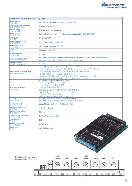
Controller RS 200 / 컨트롤러 RS 200The RS200 electronic controller is a transistor servo-controllerfor brushed permanent-magnet <strong>DC</strong> motors.The RS200 electronics enables a motor to drive and brakein one direction (2-quadrant operation). The braking effect isachieved by short-circuit braking.The RS200 servo-controller is an analogue speed regulatorthat operates on a current-regulation basis. The pulsewidth-modulatedelectronics have a high efficiency andare thus very compact. To ensure compliance with currentEMC standards, a filter is included, and the controller hasa complete electromagnetic protected housing. Thesefeatures combined with the use of shielded cables ensurethat the requirements of EN55011 Cl. B are fulfilled. There isalso a fuse on the PCB which interrupts the mains supply ifoverloaded.The RS200 electronic controller only needs a single supplyvoltage that lies within a generous range. All necessaryauxiliary voltages, including those for supplying externalcomponents are generated from this internal powersupply.RS200 컨트롤러는 브러쉬 타입 모터 제어용 트랜지스터 서보컨트롤러로, 한 방향(2-quadrant 컨트롤러)으로 동작 및 정지제어가 가능합니다. 이 때 브레이크 효과는 쇼트 회로에 의한것입니다. (모터의 +,- 쇼트시 브레이크 효과 발생)RS200 컨트롤러는 전류 제한를 통한 아날로그 속도 제어 컨트롤러로 이 PWM 회로는 효율이 높고 컴팩트 한 장점이 있습니다. 전류 EMC 표준에 따라 필터가 내장되어 있고, 전자기장보호 하우징이 적용되어 있습니다. 이러한 특징은 shield 케이블 사용과 함께 EN55011 CI의 요구 조건이기도 합니다. 그리고 PCB 상에 과부하로부터 컨트롤러를 보호하기 위한 퓨즈가 내장 되어 있습니다.RS200 컨트롤러는 단순히 한 개의 입력 전원만 있으면 되고,외부 장착 부품이나 컨트롤러 내부적으로 필요한 2차 전압들은 내부적으로 분배되어 사용 됩니다.The user has a choice of methods of providing the actualspeedsignal, either with a <strong>DC</strong> tacho-generator, a one ortwo-channel rotary encoder, or by using the speed-proportionalEMC of the motor with compensation for the current-dependentarmature-voltage drop (IxR). To select thedesired type of operation (<strong>DC</strong> tacho, encoder or IxR), theuser simply has to put a bridging plug in the correct place inthe connector strip. For applications with less stringent demandson speed control (above 500 1/min), it is possible toset speed substantially independent of load by using EMCwithout the need for a <strong>DC</strong> tacho or encoder.This EMC regulation is a low-cost solution and is also economicalon space. For speeds of rotation above 50 1/min,speed feedback can be achieved using the RE30 or RE56rotary encoders. The widest speed-control range with thegreatest precision of regulation is achieved by using oneof the <strong>DC</strong> tacho-generators TG11 or TG 52. For specificprojects, use of the MG2 sensor is also possible.사용자는 실제 속도에 대한 정보를 <strong>DC</strong> 타코제너레이터, 1~2채널 로터리 엔코더 혹은 Back EMF(IXR) 를 통해 받을 수 있으며, 속도 feedback 방법 중 (<strong>DC</strong>타코, 엔코더 혹은 IXR) 중 한가지를 선택하기 위해서는 brigde plug 를 메뉴얼에 따라 알맞게선택하시면 됩니다. 그런데 정밀한 속도 제어가 필요치 않은분야에서는 (500 rpm 이상) <strong>DC</strong> 타코나 엔코더 없이 EMC에 따라 부하로부터 독립적인 속도를 세팅하여 사용 할 수 있습니다. 이 EMC 규정은 비용적으로 저렴하며, 공간적으로도 유리합니다. 50 rpm 이상 비교적 저속제어의 경우 RE30 이나 RE56같은 로타리 타입 엔코더를 사용하여 제어 가능하며, <strong>DC</strong> 타코제너레이터 TG11 이나 TG52는 속도 제어 범위가 가장 넓고 가장 정밀한 속도 제어가 가능합니다. 특수 사양 엔코더로 MG2모델도 공급 가능합니다.When the servo-controller is ready for operation, a LEDindicator is illuminated, and there is also a digital outputsignal. Where it is necessary to use an external ballastcircuit, there is a suitable signal available at the connector tothe PCB.For connecting the servo-controller, there is a 16-pole phoenixstyleconnector with screw/plug terminals (available asan accessory). For specific projects, the RS200 electroniccontroller can be supplied with a 32-pin strip to DIN41612so that it is suitable for use in 19”-racks.For further technical data and information on terminalassignment, please see the operating manual atwww.dunkermotoren.com (download area)컨트롤러가 준비 상태가 되면 LED가 점등 되면서 디지털 출력 신호가 나옵니다. 외부 ballast 회로가 필요한 경우 PCB 상에 연결할 수 있는 커넥터가 있습니다.컨트롤러와의 연결에 있어 필요시 screw/plug 터미널 타입의 16-pole phoenix-style 커넥터를 사용할 수 있습니다. 특정 수량의 project에 대해서는 19인지 렉 사용이 가능하도록DIN41612규정에 맞게 RS200컨트롤러에 32-pin타입도 가능합니다.단자 연결 및 기술적인 데이터에 대한 자세한 사항은 홈페이지(www.dunkermotor.co.kr/www.dunkermotoren.com)에서 받아 보실 수 있습니다.(download참조)86
Controller RS 200 / 컨트롤러 RS 200Supply voltage/공급 전압Under/overvoltage protection/최소/최대 보호 전압Auxiliary voltage/내부 2차 전압Ballast circuit/발라스트 회로Fault output/오류 출력Max. continuous current/최대 정격 전류Max dynamic current/순간 최대 전류Fuses/퓨즈<strong>DC</strong> tacho voltage/<strong>DC</strong> 타코 전압Rotary incremental encoder/로타리 인크리멘털 엔코더Analog speed value/아날로그 속도 제어 값Recommended operating range/권장 속도 제어 범위Accuracy of regulation/제어 정밀도Heat-sink temperature/Heat-sink 온도Speed-target ramp/속도 가속력 조정Interference suppression/보호 등급Max. speed of rotation/최대 회전속도P-speed-control amplification/P-속도 제어 값Protection class/IP 등급Ambient temperature/사용 온도 범위Dimensions/크기12V ≤ U ≤ 50V with max. 5% ripple / 최대 5% 리플for / für 10 V > U > 60 V+5V/100mA and / +12V/40mA5 Watt effective for / 54V < U < 57V, externally extendable / 외부 확장 가능0/ 10V and / LED0 < I < 7A adjustable / 조정 가능0 < I < 15A adjustable / 조정 가능8A (MT) installed / 장착0 ... +60V5V auxiliary supply generated and automatic evaluation of 1 or 2-channel square-wave signals /5V 전압이 공급 되며, 1 혹은 2 채널 사각 신호가 출력됨.0 ... 10V– with RXI regulation minimum speed of rotation: 500 1/min– with rotary incremental encoder (e.g. RE30) minimum speed of rotation: 50 1/min– with tacho-generator (e.g. TG11) minimum speed of rotation: 5 1/min– RXI 을 이용 해서는 500 rpm 이상 제어 가능– RE30 같은 로타리 인크리멘탈 엔코더를 이용 하면 50 rpm 이상 제어 가능– TG11 같은 타코제너레이터를 이용 하면 5 rpm 이상 제어 가능.by Speed loading from 0 to 80% of torque– with IxR regulation 10%– with rotary encoder (e.g. RE30) 1%– with tacho-generator (e.g. TG11) 1%토크 범위 0~80% 까지 변화에 따른 속도 제어 편차– IxR 이용시 10%– 엔코더 이용시 (예> RE30) 1%– 타코제너레이터 이용시 (예> TG11) 1%max. 80°C thereafter current is automatically adjusted /최대 80°C 이며 이후에는 자동으로 전류값이 조정된다.adjustable from ca. 0 - 10 s / 0 - 10 s 조정 가능to EN55011 Class B6000/min0 < Pn < 9 adjustable / 조정IP000 ≤ δ ≤ 40°C163 x 100 x 28 mmPotentiometer arrangementPotentiometer 기능 참조87
- Page 4 and 5:
Why Dunkermotoren? / 왜 던커모
- Page 6 and 7:
Our Product Range / 제품군DC-Mot
- Page 9 and 10:
GR/G Selection GuideGR/G 모터 선
- Page 11 and 12:
Engineering Reference / 참조사
- Page 13 and 14:
GR 23, 4 WDimensions in mm / 규격
- Page 15 and 16:
G 30.2, 4 WDimensions in mm / 규
- Page 17 and 18:
G 30.1 / G 30.1 S, 6 W / 7 WDimensi
- Page 19 and 20:
G 30.0 / G 30.0 S, 10 W / 11 WDimen
- Page 21 and 22:
GR 42x25, 15 WDimensions in mm /
- Page 23 and 24:
GR 42x40, 20 WDimensions in mm /
- Page 25 and 26:
GR 51x30, 40 WDimensions in mm /
- Page 27 and 28:
GR 51x58, 60 WDimensions in mm /
- Page 29 and 30:
GR 53x30, 40 WDimensions in mm /
- Page 31 and 32:
GR 53x58, 60 WDimensions in mm /
- Page 33 and 34:
GR 53 SI, 40 - 60 WDimensions in mm
- Page 35 and 36: GR 63x25, 50 WDimensions in mm /
- Page 37 and 38: GR 63x55, 100 WDimensions in mm /
- Page 39 and 40: GR 63Sx55, 130 WDimensions in mm /
- Page 41 and 42: GR 63 SI, 50 - 100 WDimensions in m
- Page 43 and 44: GR 80x40, 120 WDimensions in mm /
- Page 45 and 46: GR 80x80, 240 WDimensions in mm /
- Page 47 and 48: PLG/SG Gears for DC Motors /DC 모
- Page 49 and 50: PLG 24Lengths L motor gearbox combi
- Page 51 and 52: PLG 30Lengths L motor gearbox combi
- Page 53 and 54: PLG 30 HLengths L motor gearbox com
- Page 55 and 56: PLG 32Lengths L motor gearbox combi
- Page 57 and 58: PLG 32 HLengths L motor gearbox com
- Page 59 and 60: PLG 42 KLengths L motor gearbox com
- Page 61 and 62: PLG 42 SLengths L motor gearbox com
- Page 63 and 64: PLG 52Lengths L motor gearbox combi
- Page 65 and 66: PLG 52 H - Low NoiseLengths L motor
- Page 67 and 68: PLG 60Lengths L motor gearbox combi
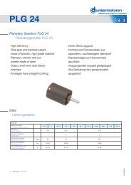
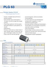
- Page 69 and 70: PLG 63Lengths L motor gearbox combi
- Page 71 and 72: PLG 75Lengths L motor gearbox combi
- Page 73 and 74: SG 45Lengths L motor gearbox combin
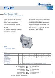
- Page 75 and 76: SG 62Lengths L motor gearbox combin
- Page 77 and 78: SG 80Lengths L motor gearbox combin
- Page 79 and 80: SG 120Lengths L motor gearbox combi
- Page 81 and 82: Data / 기술자료 E 38 R E 46 A E
- Page 83 and 84: Magnetic pulse generators /마그
- Page 85: Incremental Encoders for GR/G Motor
- Page 89 and 90: BGE 3508/6005Dimensions in mm / 규
- Page 91 and 92: BGE 3515/6010Dimensions in mm / 규
- Page 93 and 94: 4 Connector for protection covers,