Oil & Gas | Filtration - Filtration News
Oil & Gas | Filtration - Filtration News
Oil & Gas | Filtration - Filtration News

You also want an ePaper? Increase the reach of your titles
YUMPU automatically turns print PDFs into web optimized ePapers that Google loves.
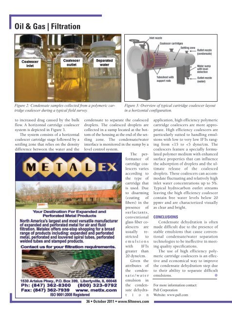
<strong>Oil</strong> & <strong>Gas</strong> | <strong>Filtration</strong>Figure 2: Condensate samples collected from a polymeric cartridgecoalescer during a typical field survey.Figure 3: Overview of typical cartridge coalescer layoutin a horizontal configuration.to increased drag caused by the bulkflow. A horizontal cartridge coalescersystem is depicted in Figure 3.The system consists of a horizontalcoalescer cartridge stage followed by asettling zone that relies on the densitydifference between the water and thecondensate to separate the coalesceddroplets. The coalesced droplets arecollected in a sump located at the bottomof the housing at the end of the settlingzone. The condensate/waterinterface is moni tored in the sump by alevel control system.The performanceofcartridge coalescersvariesaccording tothe type ofcartridge thatis used. Dueto disarming(coating offibers) in thepresence ofsurfactants,conventionalglass fiber coalescersareusually restrictedtoe m u l s i o n swith IFTsgreater than20 dyne/cm.Given theattributes ofthe condensa t e / w a t e remulsion inthe condensatedehydrati o n36 • October 2011 • www.filtnews.comapplication, high efficiency polymericcartridge coalescers are more appropriate.High efficiency coalescers areparticularly suited to handling emulsionswith low to very low IFTs rangingfrom