

Griffon 2000TDX Hovercraft - HovercraftModels.com
Griffon 2000TDX Hovercraft - HovercraftModels.com
Griffon 2000TDX Hovercraft - HovercraftModels.com

Create successful ePaper yourself
Turn your PDF publications into a flip-book with our unique Google optimized e-Paper software.
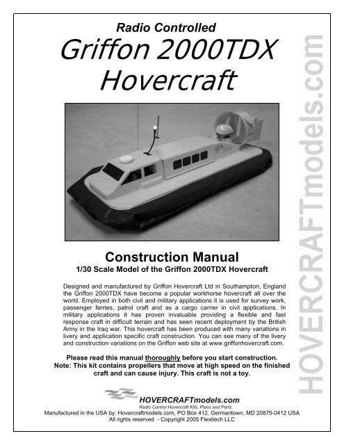
Radio Controlled<strong>Griffon</strong> <strong>2000TDX</strong><strong>Hovercraft</strong>Construction Manual1/30 Scale Model of the <strong>Griffon</strong> <strong>2000TDX</strong> <strong>Hovercraft</strong>Designed and manufactured by <strong>Griffon</strong> <strong>Hovercraft</strong> Ltd in Southampton, Englandthe <strong>Griffon</strong> <strong>2000TDX</strong> have be<strong>com</strong>e a popular workhorse hovercraft all over theworld. Employed in both civil and military applications it is used for survey work,passenger ferries, patrol craft and as a cargo carrier in civil applications. Inmilitary applications it has proven invaluable providing a flexible and fastresponse craft in difficult terrain and has seen recent deployment by the BritishArmy in the Iraq war. This hovercraft has been produced with many variations inlivery and application specific craft construction. You can see many of the liveryand construction variations on the <strong>Griffon</strong> web site at www.griffonhovercraft.<strong>com</strong>.Please read this manual thoroughly before you start construction.Note: This kit contains propellers that move at high speed on the finishedcraft and can cause injury. This craft is not a toy.HOVERCRAFTmodels.<strong>com</strong>Radio Control <strong>Hovercraft</strong> Kits, Plans and PartsManufactured in the USA by: <strong>Hovercraft</strong>models.<strong>com</strong>, PO Box 412, Germantown, MD 20875-0412 USAAll rights reserved - Copyright 2005 Flexitech LLC
<strong>Griffon</strong> <strong>2000TDX</strong> 1/30 th Scale Radio Controlled <strong>Hovercraft</strong><strong>Hovercraft</strong>models.<strong>com</strong>Acknowledgments<strong>Hovercraft</strong>models.<strong>com</strong> gratefully acknowledges the assistance of <strong>Griffon</strong> <strong>Hovercraft</strong> Ltd. inpreparing the design of this model. The design of the <strong>Griffon</strong> 2000TD and <strong>2000TDX</strong> craft andrelated intellectual property as well as the <strong>Griffon</strong> logo are all copyright <strong>Griffon</strong> <strong>Hovercraft</strong>Limited and are used by kind permission.<strong>Griffon</strong> <strong>Hovercraft</strong>’s web site can be found at www.griffonhovercraft.<strong>com</strong>_________________________________________________________To <strong>com</strong>plete the model you will require the following:• 2, 3 or 4 channel radio control system (<strong>com</strong>prising transmitter, receiver, one standard size servo)• One electronic speed controller (<strong>Hovercraft</strong>models.<strong>com</strong> Part Number ESC 20 or ESC20Rre<strong>com</strong>mended, see electrical section of this manual for more details).• 4.8 to 8.4 volt (4 to 7 cell) 600-1000mAh NiCad, NiMh or LiPoly rechargeable battery pack• Battery charger for above battery pack.• Pack of stick-on ballast weights to balance the craft with the battery weight on board. (Availableat most hobby stores).• Hinge Tape – Used for electric model airplanes (found in most RC hobby stores, DuBro #319)• Servo Tape – For holding servos in place on small models ( most hobby stores that sell RCairplanes will have this).• Glue – One tube of Polystyrene Cement, as used on plastic model kits. This will be used to gluethe parts of the kit together where required.For construction:Paint – Testors or Humbrol Paints can be used on this model, a 3oz spray can is enough to <strong>com</strong>plete themodel.Sealing - Tube of silicone bath seal.Hobby Knife – Any small sharp hobby knife or box cutter knife.Scissors – For cutting out plastic parts. Lexan or Canopy curved scissors are ideal.Note: Some knowledge of building radio controlled models is helpful to <strong>com</strong>plete this model.Please seek help from someone who has experience in building model planes or boats if you haveany doubt about a step in this manual.The mast and light illustrated on the cover of this manual is an optional addition to the model and not included in the kit________________________________________________________________Parts PreparationBefore construction starts you will need to prepare the parts for both painting and fitting together.The first task is to cut all the pieces from the vacuum formed sheets. We re<strong>com</strong>mend using small curvedscissors made for this job called canopy or Lexan scissors. Normal sharp scissors will do the job butcanopy scissors make cutting curved sections much easier.Take your time when cutting the parts out to get a clean finish. The rudders and cabin especially requiresome detailed attention. Take care on cutting the small parts and regularly check the fit to other relatedparts to get the correct fit. It is possible to tear the plastic so take extra care and go slowly. Once youhave cut out the parts lightly sand the edges with fine sandpaper to remove any burrs or rough edges.PaintingThe craft should be painted after all the parts are cut out and some construction has been started. Youwill cut out the cabin windows and assemble the thrust duct and rudder supports and fit the engine cowlon the body before you paint the craft. The best painting results will be obtained by using spray cans ofmodel paint or an airbrush if you own one.The rudder, elevators and rudder supports require painting on both sides. The upper deck requirespainting but it is not necessary to paint the lower deck as this is under the craft and cannot be seen.2
<strong>Griffon</strong> <strong>2000TDX</strong> 1/30 th Scale Radio Controlled <strong>Hovercraft</strong><strong>Hovercraft</strong>models.<strong>com</strong>Buoyancy Foam PreparationThe buoyancy foam ensures the craft floats with a good water clearance when the lift motor is turned off.Supplied in your kit is a 13 ½ x 4 ½ inch slab of white foam. It must be cut to the correct size for the craft<strong>com</strong>prising two sections. Measure and mark with a pencil on the foam two section, one 10 ½ inches insize and the other 2 inches long. Cut these out using a hobby knife or hot wire cutter if you have one.White foam cut to sizeThe two sections need to carved so they fit aroundthe lift duct. They only need to fit around a portionof the duct leaving the sides free for airflow intothe skirt. Once these are cut set them aside for themoment.Upper Deck Initial PreparationCut out the deck from its surrounding molding. The deck should be cut so that it is flush with the 1/8 th inchstep down at the edge of the deck. Once this is done you can sand the edge to a smooth finish ifrequired. Now you will cut the cabin windows out at the front of the deck.Cabin with windows cut outThe windows have been marked in the plastic on bothsides of the cabin. These are opened up to act as lift air‘cheat holes’. Using a 1/16 th drill (a Dremel drill is ideal buta handheld drill work just as well), drill a small hole in eachcorner of the cabin windows. Now using a sharp modelingknife score along the window lines between the holes.Repeat this until the score line cuts through the plastic andyou can remove the center of the window. Do this for all 4windows. Once they are cut out use fine sandpaper or asmall file to smooth any rough parts of the cut surface. Ifyou cut the window too far along the line you can simplyrepair the cut with Polystyrene Cement and it will not showone the deck is painted.Lower Deck Initial PreparationCut the lower deck out from its surrounding mold. This time the deck is cut out on the inside of the 1/8 thinch step down so that the deck is flat at the edges.Cut out and prepared lower deck.Note the deck bolt holes cut outTo prepare the lower deck forassembly the top of the lift ductshould be cut off to open up theduct. This should be cut 1/16 th inchbelow the curved part at the top ofthe duct. Only cut out the semi-circles either side of the bleed duct, not the entire hole. The air from the liftpropeller duct goes down into the skirt via the center bleed duct and inflates the skirt all around the craftperimeter. The balance of the air continues down the semi-circular lift duct and provides air pressureinside the plenum chamber made by the skirt for lift.3
<strong>Griffon</strong> <strong>2000TDX</strong> 1/30 th Scale Radio Controlled <strong>Hovercraft</strong><strong>Hovercraft</strong>models.<strong>com</strong>Upper and Lower Deck Bolt HolesThe major parts of this model are the upper and lower decks and these now need to be prepared forpainting and assembly. There are two holes marked by doughnut shapes in the top deck and three holesmarked in the same way on the lower deck. This is where 10-24 by 1 inch nylon deck bolts go to hold theupper and lower decks of the craft together. Cut, drill or punch out these holes using a 3/16 drill or punch.Upper deck with bolt holes cut outNow set the deck bolt holes in the correct place in the buoyancy foam cut earlier. Place each of the twoslabs onto the lower deck in their correct positions. Using a 3/16 th drill bit make a hole through the foam ateach deck bolt hole using the lower deck to align the drill. Once all three holes have been made removethe buoyancy foam from the lower deck and move onto the next step.Installing the Front StrutThe upper deck requires the addition of a fixing strut to be added to the cabin floor. A 10-24 bolt and nutwill secure the front of the upper deck to the lower deck. Using the supplied strip of white 0.04 thickmaterial cut a piece that is 1 ½ inch wide by 4 ¼ inches long. Mark the bolt hole location on this piece byfirst finding and marking the center line along the 4 ½ inch length. Now measure in 5/16 th inch along thatline from one side. Punch, drill or cut a 3/16 th hole center on that point.Strut installedNow test fit the lower and upper decks to locate the struton the upper deck body. First pass one 10-24 by 1 inchbolt through the center hole of the lower deck from theunderside (the side this will be on the ground when thecraft is operating) and then one bolt through the frontdeck bolt hole. Now set the deck flat on the bench in frontof you with the bolts sticking up. Now pass the front andrear foam buoyancy sections in place on the deck overthe bolts. Place the strut over the bolt end protruding fromthe front section of foam. Secure lightly in place with a nut. Now place the upper deck over the centerbolt and set squarely over the strut at the front. With a pencil mark where the strut contacts the undersideof the upper deck. Once that is done disassemble the decks. The strut can now be glued in place on theunderside of the upper deck of the craft at the marked location using Polystyrene Cement.Motor CoverThe motor cover dome is cut out to cover the thrust motor body. This molding is on the end of the lowerdeck part. It should be cut off above the webbing on the part. Trim the molding so that it covers the wiringend of the motor and just <strong>com</strong>es over the front of the motor body. It will be painted and then attached tothe motor using hook and loop at the final construction stage.4
<strong>Griffon</strong> <strong>2000TDX</strong> 1/30 th Scale Radio Controlled <strong>Hovercraft</strong><strong>Hovercraft</strong>models.<strong>com</strong>Engine Cover PreparationCut out the engine cover leaving a 1/8 th inch lip around the outer edge of the part. The step down on thepart that faces the cabin should be cut so that it is 3/8 th inch long. Again, smooth any rough edges withfine sandpaper. A small doughnut mark on the back of the cover needs to be drilled out to 1/8 th inch. Thisis where the thrust motor wires will be run through later.Engine cover cut out and preparedThe engine cover is now glued in place so that it restsagainst the rear stop molded into the upper deck. Put a smallamount of glue around the lip of the part and then place itonto the upper deck. Set the deck aside so that the glue canset in about 20 minutes.Engine cover attachedto the upper deckCutting out the thrust DuctFirst the duct is cut from the cup shape molding. Measure 3/16 th inch down from the closed end of theduct. Mark a line all around the duct at this point and cut the closedend off at this mark. Trim the open end to the point where it curvesoutward.Prepared thrust ductThe thrust duct is now cut open so that the lower edge is open andshaped into a curve. This allows it to be glued to the duct supporton the upper deck later on. The curve guide is marked into theplastic. Cut the part to that guide. You may have to trim the curvefurther for propeller clearance when testing its fit onto the craft.Cutting out the RuddersThe rudders are cut so that the tab is left at the base of the rudder and the rudder surface is flat. Holesare drilled where the rudder horn goes and these areindicated by small depressions in one of the rudders.Rudders cut out and prepared.Holes also need to be drilled in the bottom lip of the ruddersto ac<strong>com</strong>modate the tie bars that join them. Measure in1/8 th inch in on the lip from the back of the rudder and drill a1/16 th inch hole at this point. Note that the center rudderneeds two holes, one on either side of the lip. The rudderwith the horn in only needs one on the outer edge. The left-hand side rudder only needs one on the inneredge (see page 13 for more detail on the rudder tie bars).5
<strong>Griffon</strong> <strong>2000TDX</strong> 1/30 th Scale Radio Controlled <strong>Hovercraft</strong><strong>Hovercraft</strong>models.<strong>com</strong>Cutting out the Passenger Cabin CoverThis cover is cut so that fits between the engine cover and cabin on theupper deck.Cutting out the Rudder Support StructureThe rudder support structure is cut and then folded from the long strip molding. Cut out the entire stripfrom its molding and fold down the two sides carefully away from the top bar.Rudder support cut out and preparedDO NOT score the fold lines with a knife blade as the plastic willsimply break apart. It will help to warm the fold lines slightly with ahairdryer or model aircraft cover shrinking hot airgun first. Slowlyand carefully fold the sides down so that they are at 90º to the topbar of the structure. Now fold the tabs at the bottom of the sidepieces inwards at 90º to <strong>com</strong>plete the rudder support shaping.Support top bar with side bentdown ready for assemblyAssembly of the Rudder SupportNow cut out the ‘T’ shaped base of the rudder support. The curved sides of the molding should be left inplace all around the piece to add strength except on the base and each end of the ‘T’. This needs to becut flat so it can be fitted onto the upper deck and glued tothe rest of the assembly. Drill a 1/16 th inch hole wheremarked by a small dimple in the piece.The center rudder support must now be cut out. Removethe molded edges so that it makes a flat part.Start assembly by gluing the tabs at the base of the sidesof the support, under either side of the ‘T’ base. Use smallclamps to hold it in place while setting. Glue the centersupport into the assembly using the groove in the baseand the line in the top of the rudder support as a guide for location. The rudder support is now <strong>com</strong>plete.6
<strong>Griffon</strong> <strong>2000TDX</strong> 1/30 th Scale Radio Controlled <strong>Hovercraft</strong><strong>Hovercraft</strong>models.<strong>com</strong>Assembly and Installation the Rudder and Thrust DuctBend down90 degreesGlue Duct HereBend down90 degreesRudderCenterSupportRudderUpperSupportThrust DuctLeft RudderSupportRudderBase 'T'SupportRight RudderSupport'T' SupportRetaining Screw( Requires 5/64thhex key)RudderSupport andThrust DuctRear ViewBend down90 degreesBend down90 degreesGlue Tabs HereUpper DeckRudderSupportAssemblyThrust DuctPropellerRightHandRudderRudderBase 'T'SupportMotor MountGray ClipThrustMotorThrustMotorWiresRudderSupport andThrust DuctSide ViewRudderHornEngineCover'T' SupportRetaining Screw(Option to glue herewhere duct touchesengine cover)Upper DeckNote: Drawing is not to scale7
<strong>Griffon</strong> <strong>2000TDX</strong> 1/30 th Scale Radio Controlled <strong>Hovercraft</strong><strong>Hovercraft</strong>models.<strong>com</strong>Assembly of the Rudder Support and Thrust Duct.The rudder support is attached to the thrust duct using two sloped tabs on either side of the top bar. Testfit the thrust duct onto its upper deck supports so that the open curve is evenly spaced at the base of theduct. Now put the rudder assembly into the rear of the duct and mark where the sloped tabs meet theduct.View of the <strong>com</strong>peted rudder assemblyattached by the tabs glued to the thrust ductRemove the duct and rudder support from the upper deck and glue therudder support in place where it was marked. Small clamps orclothespins will be needed to keep the parts in place until they have set.Once set it can then be fitted to the upper deck.Attaching the Thrust Duct to the Upper DeckBefore assembly can begin, the thrust motor with its propeller has to be mounted on to the crafttemporarily to test for clearance. Slide one of the motors in the kit into a gray motor mount clip. Fit apropeller to the motor by drilling its hub out to 5/64 th (1.9mm). The propeller should be fitted so that themolded writing on the propeller blade is facing the motor body. It will be a tight fit onto the motor shaft.Push the propeller down on the shaft until there is 1/6 th of the shaft still showing at the base where theshaft meets the motor body. Now using some painters tape or sticky tape, mount the motor by locatingthe motor clip base onto the thrust motor post. The propeller will be just inside the thrust duct when it ismounted.Thrust duct and rudder supportmounted onto the upper deckOffer up the thrust duct into place at the rear ofthe upper deck. The front of the duct should betouching the outer corners of the engine coverand its base should rest on the upper curveddeck support. The ‘T’ base of the rudderassembly should be rested on the upright mountmolded into the rear of the upper deck. Using apencil mark through the hole on the ‘T’ base ofthe rudder assembly so that a mark is left on theupper deck upright mount. Now remove the ductassembly and drill a 1/16 th hole where the mark shows. Once this is done relocate the thrust duct andusing the supplied self-tapping #2 x 7/16 hex head screw, attach the ‘T’ base to the upper deck.The base of the thrust duct should be temporarily taped to the thrust duct mount molded into the upperdeck. Now rotate the propeller as see that it does not touch the thrust duct at any point in its travel. If itdoes, adjust the position of the duct and if necessary trim the curved parts at the bottom of the duct togive the propeller free travel all around.Once the thrust duct is located correctly, mark its position and glue the thrust duct lower edges to theupper deck curved support. You may also add a small amount of glue to each lip where it touches theengine cover to firmly fix the duct in place.8
<strong>Griffon</strong> <strong>2000TDX</strong> 1/30 th Scale Radio Controlled <strong>Hovercraft</strong><strong>Hovercraft</strong>models.<strong>com</strong>Fitting the Lift Motor MountThe lift motor is located inside the front cabin on a beam glued between the cabin walls. A white 3 inchlong by 1 inch wide strip of plastic is supplied in your kit for this. The strip is located inline with the backedge of the rear windows (towards the center of the craft). Cut and carefully fit the plastic strip so that it’sa snug fit in this position. Locate the center of the strip you have cut and fix one of the self-adhesive graymotor mount clips at this point so the open end of the clip faces downwards.Take the remaining motor in the kit and drill and fit the propeller as you did for the thrust motor by drillingthe hole in the hub out to 5/64 th inch and pushing the propeller onto the motor shaft. Be sure that thepropeller faces with the molded writing on it towards the motor body. Now push the motor into the graymotor mount clip to check its fitting.Cabin with lift motor mount fittedOffer the whole assembly up into the cabin, locateit correctly and temporarily hold it in place usingpainters or sticky tape. Rotate the propeller andsee that it turns in the center of the widened area atthe base of the cabin. It should be evenly spacedfrom the walls throughout its entire rotation. Thepropeller must also sit so its front edge (the edgetowards the base of the cabin) does not protrudebelow the cabin base.Underside view with the motor with propeller fitted inthe motor mount and the lower deck fittedYou need to now test fit the lower deck and foambuoyancy to test the correct lift duct clearance. Usingthe 10-24 by 1 inch bolts located the lower deck,buoyancy foam and into the upper deck check that thelift motor propeller does not touch the top of the lowerdeck lift duct. If it does, then trim a small amount fromthe lift duct top to give the correct clearance. Once the duct clearance is correct carefully disassemble thedecks and mark the motor mount position. You can then glue the motor mount strip in place on the cabinwalls and put to deck aside to set. Don’t be tempted to remove the motor until the glue has fully set! Oncethe glue is set remove the motor and the upper deck is ready to be painted.The upper deck, duct, passenger cabin and rudders are now ready for painting.Radar Cover/Hatch CoverSupplied in your kit is a small two-part radar dome that also doubles as ahatch cover if your finished craft is going to be a military type. Cut bothhalves out from the molding and if assembling the radar cover trim oneshorter than the other so they nest one inside the other. They are theyglued in together and put aside to set.Radar cover installedIf you’re using this as a hatch, then cut one half so that it has a 1/16 th lip allaround it and glue it onto the center of the cabin on the upper deck.9
<strong>Griffon</strong> <strong>2000TDX</strong> 1/30 th Scale Radio Controlled <strong>Hovercraft</strong><strong>Hovercraft</strong>models.<strong>com</strong>You may want to temporarily tape the heads of the bolts against the deck to hold them in place whileassembling the rest of hovercraft base. Now place the lower deck with the threaded shafts of the boltsupward on the bench.Before proceeding with the skirt assembly a 1/8 th inch bead of silicone bath seal <strong>com</strong>pound should be runaround the top side (opposite side from the deck bolt head) of the deck and the lift duct. This is important,as it will seal the skirt against the deck and stop water ingress.Silicone seal is put around the lower deckFitting the Skirt AssemblyPlace the lower deck on the bench in front ofyou with the lift duct to your left. Now pass thelower layer of the skirt over the deck bolts andlift duct so it rests on the lower deck and makescontact with the silicone seal <strong>com</strong>pound.The hole around the duct is cut slightly smaller than the duct itself to get a tight fit so you may have tostretch the skirt a little to make it fit. Next the buoyancy foam in inserted into the skirt through the openingin the top layer of the skirt. Insert the frontsection first and align the hole in the foam withthe bolt. Repeat this with the rear section offoam. The skirt top layer can now be pulledover the two bolts protruding from the topsideof the foam.Skirt fitted with foam installed insideFitting the Upper DeckThe upper deck is now placed over the bolts protruding out of the top theskirt. The front bolt protrudes through the strut and a nut is now placedon it by reaching up through the lift duct. Put a 10-24 nut onto each ofthe two other bolts. Be sure to get them tight enough to hold the deck inplace but do not over tighten them, as this will distort the deck. The craftdecks are now <strong>com</strong>plete.Front nut on top of the strutFitting the Rudder ServoA hole must be cut in the motor housing left-hand side (viewed from the front of the craft). This allows theservo shaft and arm to protrude through. A wide range of servoscan be used with this model. It was designed to take standardservos such as Futaba 148, Hitec or an Airtronics. It can also beused with any of the mini and micro servos if you want to makethe craft lighter.Servo arm protruding from the engine coverNote the ‘Z’ bend in the wire through the servo arm as shownhere:11
<strong>Griffon</strong> <strong>2000TDX</strong> 1/30 th Scale Radio Controlled <strong>Hovercraft</strong><strong>Hovercraft</strong>models.<strong>com</strong>It is worth running some silicone sealant around the servo case to ensure that any water that getsbetween the superstructure and the upper deck does not get into the servo. The servo is mounted usingservo mounting tape or it can be glued in place.Balance Weights: Stick on weights must be added to the craft to obtain a final balance if required. Theyare used to counterbalance the craft against the weight of the battery and radio equipment in the front ofthe craft. They may be located in the cabin roof, but before adding any weight try to shift the battery andradio etc. to balance the craft.Fitting the Passenger CabinThe cabin is molded to be longer that the distance between the front cabin and the motor housing. Youmust trim and fit the passenger cabin cover to be a snug fit between these two points. Carefully cut off theexcess a small piece at a time using a hobby knife or scissors until it fits. Once <strong>com</strong>plete, carefully cleanup the edge using fine sandpaper. The cover should be held in place using the supplied hook and loop inseveral locations to hold the cover firm under all operating conditions.Thrust Motor FittingThe thrust motor wires can now be soldered on just as with the lift motor and the propeller now fitted. Firstdrill out the hub to 5/64 th to accept the motor shaft. This will make the propeller a tight fit on the 2mmmotor shaft. As with the lift motor fit the two supplied capacitorsusing the same diagram shown with the lift motor instruction onpage10 for placing them. The gray clip is self-adhesive and is stuckonto the thrust motor post at the rear of the engine housing. Besure it is level. The motor can now be fitted into the gray clip and aswith lift motor, first add a little silicone seal to the clip. Feed themotor wires down through the hole in the engine housing back andinto the passenger cabin area.Thrust motor installed and wiredFitting the RuddersThe rudders are fitted using hinge tape, a tape <strong>com</strong>monly used with miniature RC electric aircraft. Youcan also use strapping or other tape as long as it is waterproof. The rudder horn is located on the ruddernearest the servo output arm. Small bumps have been molded into one of the rudders where this hornfits. Drill 1/16 inch holes at these two locations. Secure the horn using two 0-80 x 5/16 nut and boltssupplied in your kit. Once this is done the rudders can be fitted.Two views of the rudder hornin place on rudderThe rudders can now be fittedon to the supports. Theflanges at the base of eachrudder go below the ‘T’ baseof the rudder supportassembly. Cut three 1 ¼ inch lengths of hinge tape and fit them to the center of each rudder starting withthe rudder nearest the servo (with the horn on). Fix the rudder to the upright support leaving a 1/2mm gapbetween the two parts. Repeat this for the center and far side rudder. Test each rudder to make sure itmoves smoothly 20-25º either side of its center position.12
<strong>Griffon</strong> <strong>2000TDX</strong> 1/30 th Scale Radio Controlled <strong>Hovercraft</strong><strong>Hovercraft</strong>models.<strong>com</strong>Connecting the Servo to the RudderThe length of the rod depends on the servo and servo arm that you use. To locate the push rod correctlyon your servo, first make a ‘Z’ bend in the servo end of the supplied 0.025inch steel wire. Connect thisthrough the white servo arm at the 2nd hole. Center the rudder and servo in its travel. Now mark on thewire where the push rod crosses the 2 nd hole on the rudder horn. Remove the push rod and bend a 'Z'bend at that point in the arm andconnect up as shown in the photo.Servo push rod fitted. The ‘Z’ bend isused at both ends of the rod as shownhere:When the servo moves the ruddersshould freely swing 20-25º either sideof center for full throw of thetransmitter stick.Installing the Rudder Tie BarsThe rudders are now joined together using tie bars made from 0.025inch steel wire. The ties are cut fromthe steel rod supplied in your kit. Cut two, 2 inch sections of rod. Bend a ‘Z’ bend in one end of each rod.Rudder tie bars installedLine up the rudders so that they are parallel witheach other in the center position. Measure thedistance between the rudder tie bar holes in the lip ofthe rudders.Bend another ‘Z’ bend in the other end of the tiebar at the point where it will cross the hole in theopposite rudder lip. Fit the tie bars by flexing therudders slightly to ac<strong>com</strong>modate the ‘Z’ bends.Once fitted, cut off any excess wire after the ‘Z’bend.13
<strong>Griffon</strong> <strong>2000TDX</strong> 1/30 th Scale Radio Controlled <strong>Hovercraft</strong><strong>Hovercraft</strong>models.<strong>com</strong>Radio, Speed Controller and Battery Fitted into the CraftThis model is set up for forward/reverse thrust using the ILC TM moduleFinal PreparationYour <strong>Griffon</strong> <strong>2000TDX</strong> construction is now <strong>com</strong>plete! Check the craft over and be sure it’s ready to run.You can now install the thrust motor cover and then apply the decals. The diagram of the real <strong>Griffon</strong><strong>2000TDX</strong> below gives general placement for the decals.<strong>Griffon</strong> tail logo and nameEngine ventsNOTE - The propellers on this craft reach high speeds, NEVER put your handsnear the crafts propellers when it is powered on or is running. Always check forthose around you before running the craft and keep it well away from spectatorsand animals.14
<strong>Griffon</strong> <strong>2000TDX</strong> 1/30 th Scale Radio Controlled <strong>Hovercraft</strong><strong>Hovercraft</strong>models.<strong>com</strong>When starting the <strong>Griffon</strong> 2000TD Model ALWAYS take these three easy safetysteps:1 - Never fit or remove the battery when the model is power on2 - Turn the transmitter on before powering the craft on3 - Turn the craft power off before turning the transmitter offHere is a simple checklist to run for the first and each subsequent run of your RC <strong>Hovercraft</strong>:1. Check the clearance of the lift propeller in the duct. It should rotate freely and not touch any part ofthe duct in its rotation.2. Check the clearance of the thrust propeller in its duct. Adjust the motor position if required to get therequired clearance.First RunsOn your first run briefly check the lift and thrust propellers are rotating in the right direction. The lift fan willsuck out air from the skirt if it’s incorrect so this is obvious! The thrust propeller is a little more subtle.The thrust propeller will produce some thrust if it is rotated in either direction however a marked reductionin forward thrust will be seen if it is fitted backwards. When fitted correctly the writing on the propellerfaces the motor body. To produce forward thrust the propeller will rotate in a counter clockwise directionwhen viewed from the front of the craft looking towards the rudder.Once you have this all working correctly, check the balance of the craft. Watch the craft as it rises tohover. This is the pitch or front to back balance. When the balance is correct the front of the craft shouldrise very slightly before the rear. You should also watch the lateral or side-to-side rise. The craft will tendto rise on the left side (when viewed from the back of the craft) first. This is due to lift motor torque and theweight of the servo on the right hand side. You may need to adjust the battery and radio position to getthe lateral and pitch balance correct. Take your time to get it right and the craft will run better.When you are happy with the balance you are ready to start RC hovering. Get a feel for the craft, as it isvery different from a RC car or boat. On land it will always move with the camber of the land. On water thewaves and wind affect it. Note that the lift requirements vary with the surface the craft is running on.Take your <strong>Griffon</strong> 2000TD onto a lake, boating pool or swimming pool when there is smooth water. Placeit on the water and start to increase the motor speed. The skirt will inflate and the lift air pressure willincrease. Very quickly it will reach the pressure boundary and you will see the craft suddenly rise off thewater. Now slowly add throttle as the craft moves away <strong>com</strong>pensating for any wind drift with the rudders.You will notice a bow wave in front of the skirt at first. As you apply full thrust and accelerate you will seethe craft rise over the bow wave and continue to accelerate without applying more power. This is thehump speed and is the point at which the craft moves out of the depression it makes on the water whenhovering on water. It will now be hovering over the surface at full speed.To slow down just decrease the motor speed and the skirt drag will pull you back below hump speed to astanding stop very quickly.There’s a lot of fun to be had on land or at your local lake. Take your time learn how all the controlsinteract and you will be running rings round those RC boats in no time!Have fun Hovering!___________________________________________________________15
<strong>Griffon</strong> <strong>2000TDX</strong> 1/30 th Scale Radio Controlled <strong>Hovercraft</strong><strong>Hovercraft</strong>models.<strong>com</strong><strong>Griffon</strong> <strong>2000TDX</strong> RC <strong>Hovercraft</strong> Construction ManualCopyright© 2005 <strong>Hovercraft</strong>models.<strong>com</strong>Germantown, Maryland 20876USAAll rights reservedPrinted and bound in the United States of AmericaNo parts of this manual may be used or reproduced in any manner whatsoever without writtenpermission, except for brief quotations when used in reviews and critiques. You may contact us via emailvia our web site at http://www.hovercraftmodels.<strong>com</strong><strong>Hovercraft</strong>models.<strong>com</strong> gratefully acknowledges the assistance of <strong>Griffon</strong> <strong>Hovercraft</strong> Ltd. in preparing thisdesign of this model. The design of the <strong>Griffon</strong> 2000TD and <strong>2000TDX</strong> craft and related intellectualproperty as well as the <strong>Griffon</strong> logo are all copyright <strong>Griffon</strong> <strong>Hovercraft</strong> Limited and used by kindpermission. <strong>Griffon</strong>’s web site can be found at www.griffonhovercraft.<strong>com</strong>2003/2004<strong>Hovercraft</strong>models.<strong>com</strong>PO Box 412Germantown, MD 20875-0412USAPhone: +1 (301) 947 1526Web Site: http://hovercraftmodels.<strong>com</strong>For Your Notes:16