

Griffon 2000TDX Hovercraft - HovercraftModels.com
Griffon 2000TDX Hovercraft - HovercraftModels.com
Griffon 2000TDX Hovercraft - HovercraftModels.com

You also want an ePaper? Increase the reach of your titles
YUMPU automatically turns print PDFs into web optimized ePapers that Google loves.
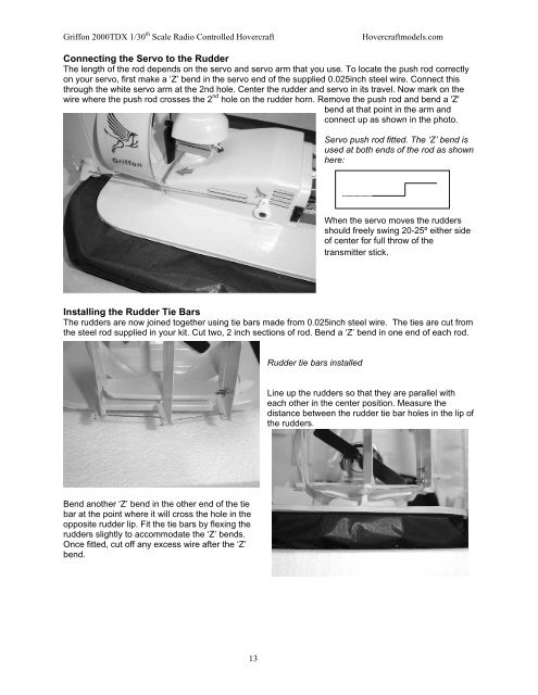
<strong>Griffon</strong> <strong>2000TDX</strong> 1/30 th Scale Radio Controlled <strong>Hovercraft</strong><strong>Hovercraft</strong>models.<strong>com</strong>Connecting the Servo to the RudderThe length of the rod depends on the servo and servo arm that you use. To locate the push rod correctlyon your servo, first make a ‘Z’ bend in the servo end of the supplied 0.025inch steel wire. Connect thisthrough the white servo arm at the 2nd hole. Center the rudder and servo in its travel. Now mark on thewire where the push rod crosses the 2 nd hole on the rudder horn. Remove the push rod and bend a 'Z'bend at that point in the arm andconnect up as shown in the photo.Servo push rod fitted. The ‘Z’ bend isused at both ends of the rod as shownhere:When the servo moves the ruddersshould freely swing 20-25º either sideof center for full throw of thetransmitter stick.Installing the Rudder Tie BarsThe rudders are now joined together using tie bars made from 0.025inch steel wire. The ties are cut fromthe steel rod supplied in your kit. Cut two, 2 inch sections of rod. Bend a ‘Z’ bend in one end of each rod.Rudder tie bars installedLine up the rudders so that they are parallel witheach other in the center position. Measure thedistance between the rudder tie bar holes in the lip ofthe rudders.Bend another ‘Z’ bend in the other end of the tiebar at the point where it will cross the hole in theopposite rudder lip. Fit the tie bars by flexing therudders slightly to ac<strong>com</strong>modate the ‘Z’ bends.Once fitted, cut off any excess wire after the ‘Z’bend.13