

Griffon 2000TDX Hovercraft - HovercraftModels.com
Griffon 2000TDX Hovercraft - HovercraftModels.com
Griffon 2000TDX Hovercraft - HovercraftModels.com

You also want an ePaper? Increase the reach of your titles
YUMPU automatically turns print PDFs into web optimized ePapers that Google loves.
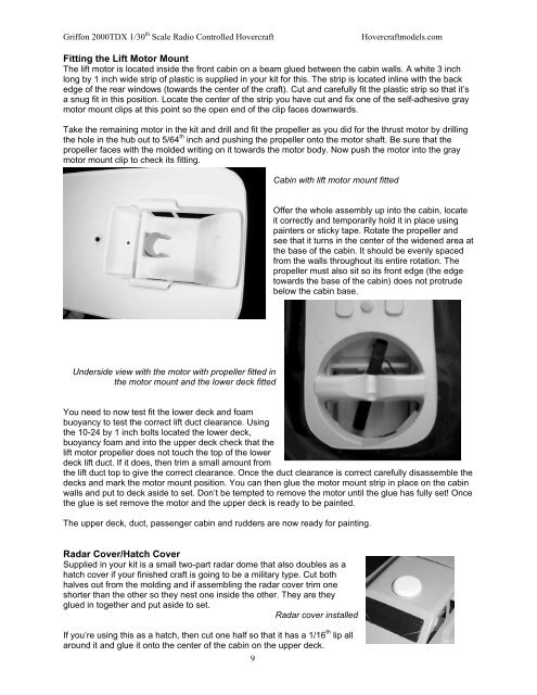
<strong>Griffon</strong> <strong>2000TDX</strong> 1/30 th Scale Radio Controlled <strong>Hovercraft</strong><strong>Hovercraft</strong>models.<strong>com</strong>Fitting the Lift Motor MountThe lift motor is located inside the front cabin on a beam glued between the cabin walls. A white 3 inchlong by 1 inch wide strip of plastic is supplied in your kit for this. The strip is located inline with the backedge of the rear windows (towards the center of the craft). Cut and carefully fit the plastic strip so that it’sa snug fit in this position. Locate the center of the strip you have cut and fix one of the self-adhesive graymotor mount clips at this point so the open end of the clip faces downwards.Take the remaining motor in the kit and drill and fit the propeller as you did for the thrust motor by drillingthe hole in the hub out to 5/64 th inch and pushing the propeller onto the motor shaft. Be sure that thepropeller faces with the molded writing on it towards the motor body. Now push the motor into the graymotor mount clip to check its fitting.Cabin with lift motor mount fittedOffer the whole assembly up into the cabin, locateit correctly and temporarily hold it in place usingpainters or sticky tape. Rotate the propeller andsee that it turns in the center of the widened area atthe base of the cabin. It should be evenly spacedfrom the walls throughout its entire rotation. Thepropeller must also sit so its front edge (the edgetowards the base of the cabin) does not protrudebelow the cabin base.Underside view with the motor with propeller fitted inthe motor mount and the lower deck fittedYou need to now test fit the lower deck and foambuoyancy to test the correct lift duct clearance. Usingthe 10-24 by 1 inch bolts located the lower deck,buoyancy foam and into the upper deck check that thelift motor propeller does not touch the top of the lowerdeck lift duct. If it does, then trim a small amount fromthe lift duct top to give the correct clearance. Once the duct clearance is correct carefully disassemble thedecks and mark the motor mount position. You can then glue the motor mount strip in place on the cabinwalls and put to deck aside to set. Don’t be tempted to remove the motor until the glue has fully set! Oncethe glue is set remove the motor and the upper deck is ready to be painted.The upper deck, duct, passenger cabin and rudders are now ready for painting.Radar Cover/Hatch CoverSupplied in your kit is a small two-part radar dome that also doubles as ahatch cover if your finished craft is going to be a military type. Cut bothhalves out from the molding and if assembling the radar cover trim oneshorter than the other so they nest one inside the other. They are theyglued in together and put aside to set.Radar cover installedIf you’re using this as a hatch, then cut one half so that it has a 1/16 th lip allaround it and glue it onto the center of the cabin on the upper deck.9