

Griffon 2000TDX Hovercraft - HovercraftModels.com
Griffon 2000TDX Hovercraft - HovercraftModels.com
Griffon 2000TDX Hovercraft - HovercraftModels.com

Create successful ePaper yourself
Turn your PDF publications into a flip-book with our unique Google optimized e-Paper software.
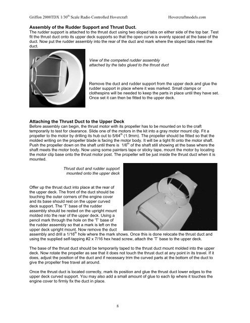
<strong>Griffon</strong> <strong>2000TDX</strong> 1/30 th Scale Radio Controlled <strong>Hovercraft</strong><strong>Hovercraft</strong>models.<strong>com</strong>Assembly of the Rudder Support and Thrust Duct.The rudder support is attached to the thrust duct using two sloped tabs on either side of the top bar. Testfit the thrust duct onto its upper deck supports so that the open curve is evenly spaced at the base of theduct. Now put the rudder assembly into the rear of the duct and mark where the sloped tabs meet theduct.View of the <strong>com</strong>peted rudder assemblyattached by the tabs glued to the thrust ductRemove the duct and rudder support from the upper deck and glue therudder support in place where it was marked. Small clamps orclothespins will be needed to keep the parts in place until they have set.Once set it can then be fitted to the upper deck.Attaching the Thrust Duct to the Upper DeckBefore assembly can begin, the thrust motor with its propeller has to be mounted on to the crafttemporarily to test for clearance. Slide one of the motors in the kit into a gray motor mount clip. Fit apropeller to the motor by drilling its hub out to 5/64 th (1.9mm). The propeller should be fitted so that themolded writing on the propeller blade is facing the motor body. It will be a tight fit onto the motor shaft.Push the propeller down on the shaft until there is 1/6 th of the shaft still showing at the base where theshaft meets the motor body. Now using some painters tape or sticky tape, mount the motor by locatingthe motor clip base onto the thrust motor post. The propeller will be just inside the thrust duct when it ismounted.Thrust duct and rudder supportmounted onto the upper deckOffer up the thrust duct into place at the rear ofthe upper deck. The front of the duct should betouching the outer corners of the engine coverand its base should rest on the upper curveddeck support. The ‘T’ base of the rudderassembly should be rested on the upright mountmolded into the rear of the upper deck. Using apencil mark through the hole on the ‘T’ base ofthe rudder assembly so that a mark is left on theupper deck upright mount. Now remove the ductassembly and drill a 1/16 th hole where the mark shows. Once this is done relocate the thrust duct andusing the supplied self-tapping #2 x 7/16 hex head screw, attach the ‘T’ base to the upper deck.The base of the thrust duct should be temporarily taped to the thrust duct mount molded into the upperdeck. Now rotate the propeller as see that it does not touch the thrust duct at any point in its travel. If itdoes, adjust the position of the duct and if necessary trim the curved parts at the bottom of the duct togive the propeller free travel all around.Once the thrust duct is located correctly, mark its position and glue the thrust duct lower edges to theupper deck curved support. You may also add a small amount of glue to each lip where it touches theengine cover to firmly fix the duct in place.8