

Griffon 2000TDX Hovercraft - HovercraftModels.com
Griffon 2000TDX Hovercraft - HovercraftModels.com
Griffon 2000TDX Hovercraft - HovercraftModels.com

Create successful ePaper yourself
Turn your PDF publications into a flip-book with our unique Google optimized e-Paper software.
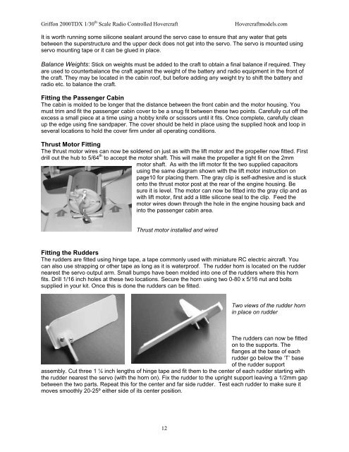
<strong>Griffon</strong> <strong>2000TDX</strong> 1/30 th Scale Radio Controlled <strong>Hovercraft</strong><strong>Hovercraft</strong>models.<strong>com</strong>It is worth running some silicone sealant around the servo case to ensure that any water that getsbetween the superstructure and the upper deck does not get into the servo. The servo is mounted usingservo mounting tape or it can be glued in place.Balance Weights: Stick on weights must be added to the craft to obtain a final balance if required. Theyare used to counterbalance the craft against the weight of the battery and radio equipment in the front ofthe craft. They may be located in the cabin roof, but before adding any weight try to shift the battery andradio etc. to balance the craft.Fitting the Passenger CabinThe cabin is molded to be longer that the distance between the front cabin and the motor housing. Youmust trim and fit the passenger cabin cover to be a snug fit between these two points. Carefully cut off theexcess a small piece at a time using a hobby knife or scissors until it fits. Once <strong>com</strong>plete, carefully cleanup the edge using fine sandpaper. The cover should be held in place using the supplied hook and loop inseveral locations to hold the cover firm under all operating conditions.Thrust Motor FittingThe thrust motor wires can now be soldered on just as with the lift motor and the propeller now fitted. Firstdrill out the hub to 5/64 th to accept the motor shaft. This will make the propeller a tight fit on the 2mmmotor shaft. As with the lift motor fit the two supplied capacitorsusing the same diagram shown with the lift motor instruction onpage10 for placing them. The gray clip is self-adhesive and is stuckonto the thrust motor post at the rear of the engine housing. Besure it is level. The motor can now be fitted into the gray clip and aswith lift motor, first add a little silicone seal to the clip. Feed themotor wires down through the hole in the engine housing back andinto the passenger cabin area.Thrust motor installed and wiredFitting the RuddersThe rudders are fitted using hinge tape, a tape <strong>com</strong>monly used with miniature RC electric aircraft. Youcan also use strapping or other tape as long as it is waterproof. The rudder horn is located on the ruddernearest the servo output arm. Small bumps have been molded into one of the rudders where this hornfits. Drill 1/16 inch holes at these two locations. Secure the horn using two 0-80 x 5/16 nut and boltssupplied in your kit. Once this is done the rudders can be fitted.Two views of the rudder hornin place on rudderThe rudders can now be fittedon to the supports. Theflanges at the base of eachrudder go below the ‘T’ baseof the rudder supportassembly. Cut three 1 ¼ inch lengths of hinge tape and fit them to the center of each rudder starting withthe rudder nearest the servo (with the horn on). Fix the rudder to the upright support leaving a 1/2mm gapbetween the two parts. Repeat this for the center and far side rudder. Test each rudder to make sure itmoves smoothly 20-25º either side of its center position.12