

Griffon 2000TDX Hovercraft - HovercraftModels.com
Griffon 2000TDX Hovercraft - HovercraftModels.com
Griffon 2000TDX Hovercraft - HovercraftModels.com

Create successful ePaper yourself
Turn your PDF publications into a flip-book with our unique Google optimized e-Paper software.
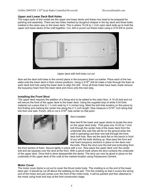
<strong>Griffon</strong> <strong>2000TDX</strong> 1/30 th Scale Radio Controlled <strong>Hovercraft</strong><strong>Hovercraft</strong>models.<strong>com</strong>Upper and Lower Deck Bolt HolesThe major parts of this model are the upper and lower decks and these now need to be prepared forpainting and assembly. There are two holes marked by doughnut shapes in the top deck and three holesmarked in the same way on the lower deck. This is where 10-24 by 1 inch nylon deck bolts go to hold theupper and lower decks of the craft together. Cut, drill or punch out these holes using a 3/16 drill or punch.Upper deck with bolt holes cut outNow set the deck bolt holes in the correct place in the buoyancy foam cut earlier. Place each of the twoslabs onto the lower deck in their correct positions. Using a 3/16 th drill bit make a hole through the foam ateach deck bolt hole using the lower deck to align the drill. Once all three holes have been made removethe buoyancy foam from the lower deck and move onto the next step.Installing the Front StrutThe upper deck requires the addition of a fixing strut to be added to the cabin floor. A 10-24 bolt and nutwill secure the front of the upper deck to the lower deck. Using the supplied strip of white 0.04 thickmaterial cut a piece that is 1 ½ inch wide by 4 ¼ inches long. Mark the bolt hole location on this piece byfirst finding and marking the center line along the 4 ½ inch length. Now measure in 5/16 th inch along thatline from one side. Punch, drill or cut a 3/16 th hole center on that point.Strut installedNow test fit the lower and upper decks to locate the struton the upper deck body. First pass one 10-24 by 1 inchbolt through the center hole of the lower deck from theunderside (the side this will be on the ground when thecraft is operating) and then one bolt through the frontdeck bolt hole. Now set the deck flat on the bench in frontof you with the bolts sticking up. Now pass the front andrear foam buoyancy sections in place on the deck overthe bolts. Place the strut over the bolt end protruding fromthe front section of foam. Secure lightly in place with a nut. Now place the upper deck over the centerbolt and set squarely over the strut at the front. With a pencil mark where the strut contacts the undersideof the upper deck. Once that is done disassemble the decks. The strut can now be glued in place on theunderside of the upper deck of the craft at the marked location using Polystyrene Cement.Motor CoverThe motor cover dome is cut out to cover the thrust motor body. This molding is on the end of the lowerdeck part. It should be cut off above the webbing on the part. Trim the molding so that it covers the wiringend of the motor and just <strong>com</strong>es over the front of the motor body. It will be painted and then attached tothe motor using hook and loop at the final construction stage.4