FL ballasts Electronic dimming PCA T5 EXCEL one4all lp ... - Tridonic
FL ballasts Electronic dimming PCA T5 EXCEL one4all lp ... - Tridonic
FL ballasts Electronic dimming PCA T5 EXCEL one4all lp ... - Tridonic
- No tags were found...

You also want an ePaper? Increase the reach of your titles
YUMPU automatically turns print PDFs into web optimized ePapers that Google loves.
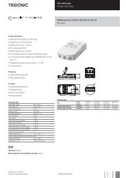
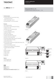
<strong>FL</strong> <strong>ballasts</strong><strong>Electronic</strong> <strong>dimming</strong><strong>T5</strong><strong>PCA</strong> <strong>T5</strong> <strong>EXCEL</strong> <strong>one4all</strong> <strong>lp</strong> Y, 3x14/24 W and 4x14/24 W<strong>EXCEL</strong> <strong>T5</strong>Product description• Processor-controlled ballast with y inside• Highest possible energy class CELMA EEI = A1 BAT 1• Noise-free precise control via DALI orDSI signal, switchDIM or corridorFUNCTION• Multi-lamp management• OEM-specific reserved memory areas• Extended DALI commands• 5-year guaranteeInterfaces• DALI• DSI• switchDIM (with memory function + selectable <strong>dimming</strong> rate)• corridorFUNCTION (individually programmable)Functions• Intelligent Temperature Guard (overtemperature protection)• Intelligent Voltage Guard (overvoltage indicationand undervoltage shutdown)• Optimum filament heating in any dimmer setting• Disconnection of filament heating from a <strong>dimming</strong> level of approx.90 % for maximum energy efficiency (SMART-Heating concept)• Fade rates between 50 ms and 90 s (min. – max.)• Automatically triggered emergency lighting value in DC mode,can be set between 1 and 100 %• For emergency lighting systems as per EN 50172• Automatic start after replacement of defective lamps• Automatic shutdown if the lamp is faulty• Dimming possible in DC mode• Backwards compatible3,54,16Technical dataMains voltage range220 – 240 VAC voltage range198 – 264 VDC voltage range176 – 280 V (lamp start ≥ 198 V DC)Mains frequency0 / 50 / 60 HzOvervoltage protection320 V AC, 1 hTyp. power input on standby< 0.5 WProtective hot restart0.5 s for AC / 0.2 s for DCDimming range, 3 lamps 5 – 100 %Dimming range, 4 lamps 1 – 100 %Lamp start possible from5 % (3 lamps), 1 % (4 lamps)Operating frequency~ 40 – 100 kHzType of protectionIP20LD214,140ÈStandards, page 3Wiring diagrams and installation examples, page 6Ordering dataTypeArticle numberPackaging,cartonPackaging,palletWeightper pc.For luminaires with 3 lamps<strong>PCA</strong> 3x14/24 <strong>T5</strong> <strong>EXCEL</strong> <strong>one4all</strong> <strong>lp</strong> Y 22176209 20 pc(s). 600 pc(s). 0.298 kgFor luminaires with 4 lamps<strong>PCA</strong> 4x14/24 <strong>T5</strong> <strong>EXCEL</strong> <strong>one4all</strong> <strong>lp</strong> Y 22176210 20 pc(s). 600 pc(s). 0.340 kgData sheet 01/14-854-4Subject to change without notice.www.tridonic.com 1
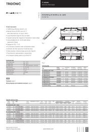
<strong>FL</strong> <strong>ballasts</strong><strong>Electronic</strong> <strong>dimming</strong>Specific technical dataLampwattageLamptypeTypeFor luminaires with 3 lampsArticlenumberDimensionsL x W x HHole spacingDLamppower2Circuitpower2EEICurrent at λ at50 Hz 230 V2 50 Hz 230 Vtc pointmax.Ambienttemperature ta33 x 14 W <strong>T5</strong> <strong>PCA</strong> 3x14/24 <strong>T5</strong> <strong>EXCEL</strong> <strong>one4all</strong> <strong>lp</strong> Y 22176209 360 x 40 x 21 mm 350 mm 42 W 46.5 W A1 BAT 0.21 A 0.97 75 °C -25 ... 60 °C3 x 24 W <strong>T5</strong> <strong>PCA</strong> 3x14/24 <strong>T5</strong> <strong>EXCEL</strong> <strong>one4all</strong> <strong>lp</strong> Y 22176209 360 x 40 x 21 mm 350 mm 72 W 73.0 W A1 BAT 0.32 A 0.97 75 °C -25 ... 55 °CFor luminaires with 4 lamps4 x 14 W <strong>T5</strong> <strong>PCA</strong> 4x14/24 <strong>T5</strong> <strong>EXCEL</strong> <strong>one4all</strong> <strong>lp</strong> Y 22176210 360 x 40 x 21 mm 350 mm 56 W 60.5 W A1 BAT 0.27 A 0.97 75 °C -25 ... 60 °C4 x 24 W <strong>T5</strong> <strong>PCA</strong> 4x14/24 <strong>T5</strong> <strong>EXCEL</strong> <strong>one4all</strong> <strong>lp</strong> Y 22176210 360 x 40 x 21 mm 350 mm 96 W 97.5 W A1 BAT 0.43 A 0.97 75 °C -25 ... 50 °C1 According to the EU directives on ecodesign requirements (EC) No. 245/2009 and (EC) No. 347/2010.2 Valid at 100 % <strong>dimming</strong> level.3 +10 °C to ta max: unrestricted <strong>dimming</strong>. -25 °C to +10 °C: unrestricted <strong>dimming</strong> from 100 % to 30 %.-25 °C to +10 °C, <strong>dimming</strong> below 30 %: malfunction possible but no damage to ECG. This applies to AC and DC operation.Data sheet 01/14-854-4Subject to change without notice.www.tridonic.com 2
<strong>FL</strong> <strong>ballasts</strong><strong>Electronic</strong> <strong>dimming</strong>StandardsEN 55015EN 60929EN 61000-3-2EN 61347-2-3EN 61547Suitable for emergency installations according toEN 50172CISPR 15CISPR 22IEC 60929IEC 61000-3-2IEC 61347-2-3IEC 61547IEC 62386 (according to DALI standard V1)Lamp starting characteristicsWarm startStarting time 0.5 s with ACStarting time 0.2 s with DCStart at any <strong>dimming</strong> levelAC operationMains voltage220–240 V 50/60 Hz198–264 V 50/60 Hz including safetytolerance (±10 %)202–254 V 50/60 Hz including performancetolerance (+6 % / -8 %)DC operation220–240 V 0 Hz198–280 V 0 Hz certain lamp start176–280 V 0 Hz operating rangeUse in emergency lighting installations according toEN 50172 or for emergency luminaires accordingto EN 61347-2-3 appendix J.Mains currents in DC operation (at 70 % light output)Wattage Mains current atMains current atTypeUn = 220 VDCUn = 240 VDC<strong>PCA</strong> 3x14/24 <strong>T5</strong> <strong>EXCEL</strong> <strong>one4all</strong> <strong>lp</strong> X 3x14 W 0.17 A 0.16 A<strong>PCA</strong> 3x14/24 <strong>T5</strong> <strong>EXCEL</strong> <strong>one4all</strong> <strong>lp</strong> X 3x24 W 0.28 A 0.26 A<strong>PCA</strong> 4x14/24 <strong>T5</strong> <strong>EXCEL</strong> <strong>one4all</strong> <strong>lp</strong> X 4x14 W 0.22 A 0.21 A<strong>PCA</strong> 4x14/24 <strong>T5</strong> <strong>EXCEL</strong> <strong>one4all</strong> <strong>lp</strong> X 4x24 W 0.37 A 0.34 ABallast lumen factor AC operation (AC-BLF) EN 60929 8.1WattageAC-BLF atTypeU = 230 VAC<strong>PCA</strong> 3x14/24 <strong>T5</strong> <strong>EXCEL</strong> <strong>one4all</strong> <strong>lp</strong> X 3x14 W 0.99<strong>PCA</strong> 3x14/24 <strong>T5</strong> <strong>EXCEL</strong> <strong>one4all</strong> <strong>lp</strong> X 3x24 W 0.99<strong>PCA</strong> 4x14/24 <strong>T5</strong> <strong>EXCEL</strong> <strong>one4all</strong> <strong>lp</strong> X 4x14 W 0.99<strong>PCA</strong> 4x14/24 <strong>T5</strong> <strong>EXCEL</strong> <strong>one4all</strong> <strong>lp</strong> X 4x24 W 0.99The ballast lumen factor for AC operation (AC-BLF) does not alter from Un = 198 V AC to Un = 254 V AC.The ballast lumen factor for DC operation (DC-BLF) on the basis of an automatic power reduction of the <strong>ballasts</strong>(default value is 70 %) will be smaller than AC. It does not alter in the DC operating range (198–280 V DC).Harmonic distortion in the mains supply (at 230 V / 50 Hz)Type Wattage THD 3 5 7 9 11<strong>PCA</strong> 3x14/24 <strong>T5</strong> <strong>EXCEL</strong> <strong>one4all</strong> <strong>lp</strong> X 3x14 W 8.40 6.65 1.97 2.17 2.09 1.36<strong>PCA</strong> 3x14/24 <strong>T5</strong> <strong>EXCEL</strong> <strong>one4all</strong> <strong>lp</strong> X 3x24 W 7.98 6.23 1.76 1.75 2.31 1.04<strong>PCA</strong> 4x14/24 <strong>T5</strong> <strong>EXCEL</strong> <strong>one4all</strong> <strong>lp</strong> X 4x14 W 8.67 6.97 2.85 1.86 1.49 1.19<strong>PCA</strong> 4x14/24 <strong>T5</strong> <strong>EXCEL</strong> <strong>one4all</strong> <strong>lp</strong> X 4x24 W 7.52 6.37 1.53 1.94 1.04 1.08Emergency unitsThe “<strong>PCA</strong> <strong>T5</strong> <strong>EXCEL</strong> <strong>lp</strong> x” <strong>ballasts</strong> are compatiblewith all emergency units from <strong>Tridonic</strong>. See the table inthe data sheet. Also all “5-pole” emergency units canbe used. When used with other emergency units testsare necessary.Temperature rangeUnlimited <strong>dimming</strong> range from 10 °C to ta max.-25 °C to +10 °C: <strong>dimming</strong> operation from 100 %to 30 %. If dimm level goes below 30 % malfunctionpossible, but no electronic ballast damage.This applies to AC and DC operation.Lamp type recognitionEach of teh lamps for wich the control gear is designedwill be operated correctly according the lampspecification. The currently used lamp is recognisedduring the start up process.To avoid an incorrect lamp recognition due to fastmultiple ON / OFF switches, new lamp data are onlyrestored if the lamp has operated for at least 5seconds.Data sheet 01/14-854-4Subject to change without notice.www.tridonic.com 3
<strong>FL</strong> <strong>ballasts</strong><strong>Electronic</strong> <strong>dimming</strong>DimmingDimming curve is adapted to the eye sensitiveness.Dimming range:4-lamp: 1 % to 100 %, 3-lamp: 5 % to 100 %Digital control with:• DSI signal: 8 bit Manchester CodeSpeed 1 % to 100 % in 1.4 s• DALI signal: 16 bit Manchester CodeMaximum speed 1 % to 100 % in 550 ms(adjustable between 50 ms and 90 s)Programmable parameter:Minimum <strong>dimming</strong> levelMaximum <strong>dimming</strong> levelDefaults 3-lamp minimum = 5 %maximum = 100 %Defaults 4-lamp minimum = 1 %maximum = 100 %Control input (DA/D1, DA/D2)Digital DALI signal or a push-to-make switch(switchDIM) can be wired on the same terminals(DA and DA).Digital signal DALI/DSIThe control input is non-polar and protected againstaccidental connection with a mains voltage up to264 V. The control signal is not SELV. Control cable hasto be installed in accordance to the requirements oflow voltage installations.Different functions depending on each module.SMART interfaceAn additional interface for the direct connection ofthe SMART-LS II <strong>lp</strong> 1) light sensor. The sensor registersactual ambient light and maintains the individuallydefined lux level.After every mains reset the SMART interface automaticallychecks for an installed sensor. With thesensor installed the <strong>PCA</strong> <strong>T5</strong> <strong>EXCEL</strong> <strong>one4all</strong> <strong>lp</strong> xautomatically runs in the constant lux level mode.ON/OFF switch via mains, switchDIM or DALI/DSIsignal.DALI/DSI signal = 0 switches off,DALI/DSI signal ≥ 1 switches on.With relative DALI <strong>dimming</strong> commands (e.g. up, downetc.) or switchDIM signals it is possible to change thecontrolled light level temporarily.Temporarily means that after a switching cycle OFF/ON command the ballast will start at the preset valuedetermined by the SMART-LS II <strong>lp</strong>. The installation ofthe two wire bus is according to the appropriate lowvoltage regulations.switchDIMIntegrated switchDIM function allows a directconnection of a push to make switch for <strong>dimming</strong>and switching.1)SMART-LS II <strong>lp</strong>: article number 86458258Dimming characteristics<strong>PCA</strong> <strong>T5</strong> <strong>EXCEL</strong> <strong>one4all</strong> <strong>lp</strong>digital <strong>dimming</strong> value255225200DALI175DSI15012510075502500 10 20 30 40 50 60 70 80 90 100relative lighting level in %Dimming characteristics as seen by the human eyeBrief push (< 0.6 s) switches ballast ON and OFF. The<strong>ballasts</strong> switch-ON at light level set at switch-OFF.When the push to make switch is held, <strong>PCA</strong> <strong>ballasts</strong>are dimmed. After repush the <strong>PCA</strong> is dimmed in theopposite direction.The switchDIM fade time is set to 3 s from min. tomax. in the factory settings. With a 20 s push to thepush to make switch this fade time can be changedto 6 s. In this instance the switchDIM application willbe synchronized to 50 % light level after 10 s and after20 s the light level rises to 100 % with the new fadetime.At every synchronizsation (10 s keystroke) the devicewill reset to 3 s (factory setting)In installations with <strong>PCA</strong>s with different <strong>dimming</strong> levelsor opposite <strong>dimming</strong> directions (e.g. after a systemextension), all <strong>PCA</strong>s can be synchronized to 50 %<strong>dimming</strong> level by a 10 s push.Use of push to make switch with indicator lamp is notpermitted.Deactivation: If the corridorFUNCTION is wronglyactivated in a switchDIM system (for example aswitch is used instead of pushbutton), there is theoption of installing a pushbutton and deactivating thecorridorFUNCTION mode by five short pushes of thebutton within three seconds.switchDIM and corridorFUNCTION are very simple toolsfor controlling <strong>ballasts</strong> with conventional momentaryactionswitches or motion sensors.To ensure correct operation a sinusoidal mains voltagewith a frequency of 50 Hz or 60 Hz is required at thecontrol input.Special attention must be paid to achieving clear zerocrossings.Serious mains faults may impair the operation ofswitchDIM and corridorFUNCTION.Energy saving<strong>PCA</strong> <strong>T5</strong> <strong>EXCEL</strong> <strong>one4all</strong> <strong>lp</strong>mains power in %1009080706050403020100100 90 80 70 60 50 40 30 20 15 10 5 4 3 2 1<strong>dimming</strong> level in %Backwards compatibility:With a simple key combination a<strong>PCA</strong> <strong>T5</strong> <strong>EXCEL</strong> <strong>lp</strong> x can be reset as a normal<strong>PCA</strong> <strong>EXCEL</strong> from the previous generation. Synchronisationsimply has to take place three times withinone minute (3 x 10 s). To activate the “x” settingsagain, synchronisation has to take place four timeswithin one minute.switchDIM <strong>PCA</strong> <strong>T5</strong> <strong>EXCEL</strong> <strong>one4all</strong> <strong>lp</strong> XDSINL2345 DA / D16 DA / D223456DA / D1DA / D2DSI <strong>PCA</strong> <strong>T5</strong> <strong>EXCEL</strong> <strong>one4all</strong> <strong>lp</strong> XDALI23456DA / D1DA / D2DALI <strong>PCA</strong> <strong>T5</strong> <strong>EXCEL</strong> <strong>one4all</strong> <strong>lp</strong> XDimmable <strong>ballasts</strong> from <strong>Tridonic</strong> have to be earthed.Loading of automatic circuit breakersAutomatic circuit breaker type C10 C13 C16 C20 B10 B13 B16 B20Installation Ø 1.5 mm 2 1.5 mm 2 1.5 mm 2 2.5 mm 2 1.5 mm 2 1.5 mm 2 1.5 mm 2 2.5 mm 2<strong>PCA</strong> 3x14/24 <strong>T5</strong> <strong>EXCEL</strong> <strong>one4all</strong> <strong>lp</strong> X 16 22 32 36 8 11 16 18<strong>PCA</strong> 4x14/24 <strong>T5</strong> <strong>EXCEL</strong> <strong>one4all</strong> <strong>lp</strong> X 14 22 32 34 7 11 16 17Continuous operation: to calculate the protective saftey switch see main current, page 1Data sheet 01/14-854-4Subject to change without notice.www.tridonic.com 4
<strong>FL</strong> <strong>ballasts</strong><strong>Electronic</strong> <strong>dimming</strong>corridorFUNCTIONActivation: To activate the corridorFUNCTION a voltageof 230 V simply has to be applied for five minutes atD1, D2. The unit will then switch automatically to thecorridorFUNCTION.Deactivation: If the corridorFUNCTION is wronglyactivated in a switchDIM system (for example aswitch is used instead of pushbutton), there is theoption of installing a pushbutton and deactivating thecorridorFUNCTION mode by five short pushes of thebutton within three seconds.The corridorFUNCTION V2 offers the added benefit of asecond and third preprogrammed profile.Application and functionallity of profiles see usermanual corridorFUNCTION.Intelligent Temperature GuardThe intelligent temperature guard protects the<strong>PCA</strong> <strong>T5</strong> <strong>EXCEL</strong> <strong>lp</strong> x from thermal overheating byreducing the output power or switching off in case ofoperation above the thermal limits of the luminaire orballast. Depending on the luminaire design, the ITGoperates at about 5 to 10 °C above Tc temperature.plugADDRESSING – simple handling, comissioningand wiringThe new plug&play solution simplifies handling.By attaching different colored marked plugs to theSMART-Interface, group addresses are assigned tothe <strong>PCA</strong> <strong>T5</strong> <strong>EXCEL</strong> <strong>one4all</strong> <strong>lp</strong> x.This supersedes a single addressing and the devicescan be put into operation without any additiona<strong>lp</strong>rogramming. Another significant advantage of thisconcept is in case of exchange and no limits to 64DALI addresses. Ideal for RGB applications and costeffectivesystem solutions with simple controllers.Simple – Quick – Plug & Play!Intelligent Voltage GuardIntelligent Voltage Guard is the name of the newelectronic monitor from <strong>Tridonic</strong>. This inno vativefeature of the <strong>PCA</strong> family of control gear from <strong>Tridonic</strong>immediately shows if the mains voltage rises above orfalls below certain thresholds. Measures can then betaken quickly to prevent damage to the control gear.• If the mains voltage rises above approx. 305 V(voltage depends on the ballast type), the lampstarts flashing on and off.• This signal “demands” disconnection of thepower supply to the lighting system.• The active-current-control of these control gearsis protected against failure caused by the high mainscurrents generated as a result of mains undervoltage.The switch off level depends on lamp wattageand is typically < 140 V.Installation instructionsOperating voltageWiring type and cross sectionThe wiring can be solid cable with a cross section of0.5 to 0.75 mm² for push terminal and 0.5 mm² forIDC terminal. For the push-wire connection you haveto strip the insulation (8–9 mm).Type Wattage Uout<strong>PCA</strong> 3x14/24 <strong>T5</strong> <strong>EXCEL</strong> <strong>one4all</strong> <strong>lp</strong> X 3x14 W 430 V<strong>PCA</strong> 3x14/24 <strong>T5</strong> <strong>EXCEL</strong> <strong>one4all</strong> <strong>lp</strong> X 3x24 W 430 V<strong>PCA</strong> 4x14/24 <strong>T5</strong> <strong>EXCEL</strong> <strong>one4all</strong> <strong>lp</strong> X 4x14 W 430 V<strong>PCA</strong> 4x14/24 <strong>T5</strong> <strong>EXCEL</strong> <strong>one4all</strong> <strong>lp</strong> X 4x24 W 430 Vwire preparation:0.5 – 0.75 mm²8 – 9 mmWiring adviceThe lead length is dependent on the capacitance of the cable.Ballast Terminal Maximum capacitance allowedType Cold Middle Hot Cold Middle Hot<strong>PCA</strong> 3x14/24 <strong>T5</strong> <strong>EXCEL</strong> <strong>one4all</strong> <strong>lp</strong> X 7, 8 9, 10, 14, 12, 13 100 pF 50 pF 100 pF15, 16, 17<strong>PCA</strong> 4x14/24 <strong>T5</strong> <strong>EXCEL</strong> <strong>one4all</strong> <strong>lp</strong> X 14, 15, 16, 17 7, 8, 9, 10 12, 13, 18, 19 200 pF 50 pF 100 p<strong>FL</strong>oosen wire throughtwisting and pullingWith standard solid wire 0.5/0.75 mm² the capacitance of the lead is 30–80 pF/m.This value is influenced by the way the wiring is made.Lamp connection should be made with symmetrical wiring.3-lamp devices: Hot and cold leads should be separated as much as possible.4-lamp devices: Middle and hot leads should be separated as much as possible.Hot leads (9, 10, 15, 16) and cold leads (11, 12, 13, 14) should be separated as much as possible.When using two or more dimmable <strong>ballasts</strong> in one luminaire with separate <strong>dimming</strong> controls, the lamp leads mustbe kept separate.Distance to plate: 5 – 10 mm(ideal distance for optimal symmetrical light)Data sheet 01/14-854-4Subject to change without notice.www.tridonic.com 5
<strong>FL</strong> <strong>ballasts</strong><strong>Electronic</strong> <strong>dimming</strong>controlsignal2345 DA/D16 DA/D278910171615141312controlsignal2345 DA/D16 DA/D2789101918171615141312* leads 12, 13: keep wires short, max. 1.0 m** leads 9, 10, 14, 15, 16, 17: keep wires short, max. 0.5 mleads 7, 8: max. 2.0 m<strong>PCA</strong> <strong>T5</strong> <strong>EXCEL</strong> <strong>one4all</strong> <strong>lp</strong> X 3x14/24 W* leads 12, 13, 18, 19: keep wires short, max. 1.0 m** leads 7, 8, 9, 10: keep wires short, max. 0.5 mleads 14, 15, 16, 17: max. 2.0 m<strong>PCA</strong> <strong>T5</strong> <strong>EXCEL</strong> <strong>one4all</strong> <strong>lp</strong> X 4x14/24 WDimmable <strong>ballasts</strong> from <strong>Tridonic</strong> have to be earthed.RFI• Connection to the lamps of the hot leads mustbe kept as short as possible• Mains leads should be kept apart from lamp leads(ideally 5–10 cm distance)• Do not run mains leads adjacent to theelectronic ballast• Twist the lamp leads• Keep the distance of lamp leads from themetal work as large as possible• Mains wiring to be twisted when through wiring• Keep the mains leads inside the luminaire as shortas possibleGeneral advise<strong>Electronic</strong> <strong>ballasts</strong> are virtually noise free.Magnetic fields generated during the ignition cyclecan cause some background noise but only for afew milliseconds.Operation on DC voltageOur <strong>ballasts</strong> are construed to operate DC voltage andpulsed DC voltage.To operate <strong>ballasts</strong> with pulsed DC voltage the polarityis absolute mandatory.23456–+DADAProgrammingWith appropriate software and a USB interfacedifferent functions can be activated and variousparameters can be configured in the new<strong>PCA</strong> <strong>T5</strong> <strong>EXCEL</strong> <strong>one4all</strong> <strong>lp</strong> x. All that is neededis a DALI-USB and the software.configTOOLFull version for programming all the functionsand parameters.pcaCONFIGURATORFor programming the corridorFUNCTION, deviceconfiguration (fade time, ePowerOnLevel, etc.)DC level, compatibility settings, and startup dateand for resetting.corridorFUNCTION CONFIGURATORFor activating and deactivating the corridorFUNCTIONand for project-specific programming of the<strong>PCA</strong> <strong>T5</strong> <strong>EXCEL</strong> <strong>one4all</strong> <strong>lp</strong> x units.PELNNLDALIPSUSBSCINL’2345623456PELNDA / D1DA / D2PELNDA / D1DA / D2Isolation and electric strength testing ofluminaires<strong>Electronic</strong> devices can be damaged by high voltage.This has to be considered during the routine testing ofthe luminaires in production.According to IEC 60598-1 Annex Q (informative only!)or ENEC 303-Annex A, each luminaire should be submittedto an isolation test with 500 V DC for 1 second.This test voltage should be connected between theinterconnected phase and neutral terminals and theearth terminal.The isolation resistance must be at least 2 MΩ.As an alternative, IEC 60598-1 Annex Q describes atest of the electrical strength with 1500 V AC (or 1.414x 1500 V DC). To avoid damage to the electronicdevices this test must not be conducted. For further technical information please visitwww.tridonic.comPC and the“corridorFUNCTION CONFIGURATOR”software toolany number of ECGs23456PELNDA / D1DA / D2Wiring diagram for programmingData sheet 01/14-854-4Subject to change without notice.www.tridonic.com 6