Digital dimmable ballasts for fluorescent lamps EXCEL ... - Tridonic
Digital dimmable ballasts for fluorescent lamps EXCEL ... - Tridonic
Digital dimmable ballasts for fluorescent lamps EXCEL ... - Tridonic
- No tags were found...

You also want an ePaper? Increase the reach of your titles
YUMPU automatically turns print PDFs into web optimized ePapers that Google loves.
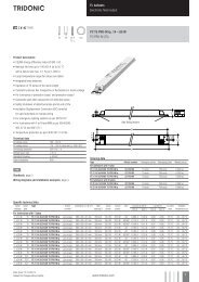
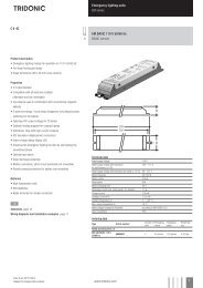
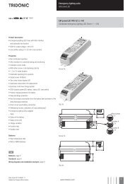
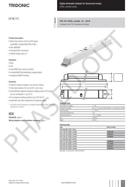
<strong>Digital</strong> <strong>dimmable</strong> <strong>ballasts</strong> <strong>for</strong> <strong>fluorescent</strong> <strong>lamps</strong><strong>EXCEL</strong> one4all seriesProduct description• Noise-free precise control via DSI signal,switchDIM, corridorFUNCTION or DALI• DALI-MEMORY• Extended DALI commands• CELMA energy class A1 1)Interfaces• DALI• DSI• switchDIM (with memory function)• corridorFUNCTION (individually programmable)• Integrated SMART-InterfaceFunctions• Optimum filament heating in any dimmer setting• Fade rates between 50 ms and 90 s (min-max.)• Automatically triggered emergency lighting value in DC mode,can be set between 1 and 70 %• For emergency lighting systems as per EN 50172• Automatic start after replacement of defective <strong>lamps</strong>1)according to the EU directives on ecodesign requirements (EC) No. 245/2009and (EC) No. 347/2010ÈStandards, page 3Wiring diagrams and installation examples, page 5TC-FTC-LPCA TCL <strong>EXCEL</strong> one4all, 18 – 80 WCompact and T5c <strong>fluorescent</strong> <strong>lamps</strong>Technical dataPower input on standby< 1 WProtective hot restart 0.6 s / 1.5 s <strong>for</strong> AC (55 W, 80 W, 2 x 18 W and 2 x 55 W)Dimming range 3 – 100 %Lamp start possible from 3 %Operating frequency~40 – 100 kHzLife50,000 hHeight28 mmOrdering dataTypeArticle numberFor luminaires with 1 lampPCA 1/36 TCL <strong>EXCEL</strong> one4all 22085346PCA 1/55 TCL <strong>EXCEL</strong> one4all 22085387PCA 1/80 TCL <strong>EXCEL</strong> one4all 22089004For luminaires with 2 <strong>lamps</strong>PCA 2/18 TCL <strong>EXCEL</strong> one4all 22086840PCA 2/36 TCL <strong>EXCEL</strong> one4all 22176469PCA 2/40 TCL <strong>EXCEL</strong> one4all 22085371PCA 2/55 TCL <strong>EXCEL</strong> one4all 22085393Packaging: 10 pieces/carton, 580 pieces/palletPHASED OUTData sheet 10/11-368-7Subject to change without notice.www.tridonic.com 1
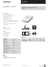
<strong>Digital</strong> <strong>dimmable</strong> <strong>ballasts</strong> <strong>for</strong> <strong>fluorescent</strong> <strong>lamps</strong><strong>EXCEL</strong> one4all seriesDimmingDimming range 3 % to 100 %<strong>Digital</strong> control with:• DSI signal: 8 bit Manchester CodeMaximum speed 3 % to 100 % in 1.4 s• DALI signal: 16 bit Manchester CodeMaximum speed 3 % to 100 % in 0.5 sProgrammable parameter:Minimum dimming levelMaximum dimming levelDefault minimum = 3 %Programmable range 3 % ≤ MIN ≤ 49 %Default maximum = 100 %Programmable range 100 % ≥ MAX ≥ 50 %Dimming curve that is friendly to the eye.Control input (D1/DA, D2/DA)<strong>Digital</strong> DALI/DSI signal or switchDIM can be wiredon the same terminals (D1/DA and D2/DA).<strong>Digital</strong> signal DALI/DSIThe control input is non-polar and protectedagainst accidental connection with a mains voltageup to 264 V. The control signal is not SELV. Controlcable should be installed in accordance to therequirements of low voltage installations.Different functions depending on each module.SMART interfaceAn additional interface <strong>for</strong> the direct connection ofthe SMART-LS light sensor. The sensor registersactual ambient light and maintains the individuallydefined lux level.After every mains reset the SMART interface automaticallychecks <strong>for</strong> an installed sensor. With thesensor installed the PCA <strong>EXCEL</strong> automatically runsin the constant lux level mode.ON/OFF-Switch via mains, switchDIM or DALI/DSIsignal.DALI/DSI signal = 0 switches off,DALI/DSI signal ≥ 1 switches on.Dimming with DALI or a DSI signal with theSMART-LS installed is not possible.switchDIM enables a temporary change oflight level.The installation of the two wire bus is accordingto the appropriate low voltage regulations.Dimming characteristics PCA <strong>EXCEL</strong><strong>Digital</strong> dimming value255225200DALI175DSI15012510075502500 10 20 30 40 50 60 70 80 90 100Relative lighting level %Dimming characteristics as seen by the human eyeswitchDIMIntegrated switchDIM function allows a directconnection of a push to make switch <strong>for</strong> dimmingand switching.Brief push (< 0.6 s) switches ballast ON and OFF.The <strong>ballasts</strong> switch-ON at light level set at switch-OFF.When the push to make switch is held, PCA<strong>ballasts</strong> are dimmed. After repush the PCA isdimmed in the opposite direction.In installations with PCAs with different dimminglevels or opposite dimming directions (e.g. after asystem extension), all PCAs can be synchronizedto 50 % dimming level by a 10 s push.Use of push to make switch with indicator lamp isnot permitted.switchDIM and corridorFUNCTION are very simpletools <strong>for</strong> controlling <strong>ballasts</strong> with conventionalmomentary-action switches or motion sensors.To ensure correct operation a sinusoidal mains voltagewith a frequency of 50 Hz or 60 Hz is requiredat the control input.Special attention must be paid to achieving clearzero crossings.Serious mains faults may impair the operation ofswitchDIM and corridorFUNCTION.Energy Savings PCA <strong>EXCEL</strong>Mains power in %1009080706050403020100100 90 80 70 60 50 40 30 20 15 10 5 4 3 2 1Dimming level in %DALIDSI234DSI PCA TCL <strong>EXCEL</strong> one4allNL234DALI PCA TCL <strong>EXCEL</strong> one4all6 D1 / DA7 D2 / DA6 D1 / DA7 D2 / DA23467switchDIM PCA TCL <strong>EXCEL</strong> one4allLoading of automatic circuit breakersAutomatic circuit breaker type C10 C13 C16 C20 B10 B13 B16 B20Installation Ø 1.5 mm 2 1.5 mm 2 1.5 mm 2 2.5 mm 2 1.5 mm 2 1.5 mm 2 1.5 mm 2 2.5 mm 2PCA 1/36 TCL <strong>EXCEL</strong> 30 50 70 76 15 25 35 38PCA 1/40 TCL <strong>EXCEL</strong> 30 50 70 76 15 25 35 38PCA 1/55 TCL <strong>EXCEL</strong> 20 30 40 46 10 15 20 23PCA 1/80 TCL <strong>EXCEL</strong> 10 20 30 30 5 10 15 15PCA 2/18 TCL <strong>EXCEL</strong> 10 12 16 20 5 6 8 10PCA 2/24 TCL <strong>EXCEL</strong> 16 20 24 30 8 10 12 15PCA 2/36 TCL <strong>EXCEL</strong> 10 20 30 30 5 10 15 15PCA 2/40 TCL <strong>EXCEL</strong> 10 20 30 30 5 10 15 15PCA 2/55 TCL <strong>EXCEL</strong> 10 14 18 20 5 7 9 10PHASED OUTData sheet 10/11-368-7Subject to change without notice.www.tridonic.com 4
<strong>Digital</strong> <strong>dimmable</strong> <strong>ballasts</strong> <strong>for</strong> <strong>fluorescent</strong> <strong>lamps</strong><strong>EXCEL</strong> one4all seriesInstallation instructionsWiring type and cross sectionThe wiring can be solid cable with a cross section of0.5 to 1.5 mm² <strong>for</strong> push terminal and 0.5 mm² <strong>for</strong>concut terminal. For the push-wire connection youhave to strip the insulation (7.5–8.5 mm).wire preparation:0.5 – 1.5 mm²7.5 – 8.5 mmOutput voltageType Wattage U outPCA 1/36 TCL <strong>EXCEL</strong> 1x36 W 250 VPCA 1/40 TCL <strong>EXCEL</strong> 1x40 W 300 VPCA 1/55 TCL <strong>EXCEL</strong> 1x55 W 300 VPCA 1/80 TCL <strong>EXCEL</strong> 1x80 W 400 VPCA 2/18 TCL <strong>EXCEL</strong> 2x18 W 250 VPCA 2/24 TCL <strong>EXCEL</strong> 2x24 W 250 VPCA 2/36 TCL <strong>EXCEL</strong> 2x36 W 250 VPCA 2/40 TCL <strong>EXCEL</strong> 2x40 W 300 VPCA 2/55 TCL <strong>EXCEL</strong> 2x55 W 300 VRFI• Connection to the <strong>lamps</strong> of the hot leads mustbe kept as short as possible• Mains leads should be kept apart from lamp leads(ideally 5–10 cm distance)• Do not run mains leads adjacent to theelectronic ballast• Twist the lamp leads• Keep the distance of lamp leads from themetal work as large as possible• Ballast must be earthed• Mains wiring to be twisted when through wiring• Keep the mains leads inside the luminaire as shortas possibleImportant advise• When using two or more <strong>dimmable</strong> <strong>ballasts</strong> in oneluminaire with separate dimming controls, thelamp leads must be kept separate• All <strong>lamps</strong> must have the same length leadWiring adviceThe lead length is dependent on the capacitance of the cable.Ballast Terminal Maximum capacitance allowedType Cold Hot Cold HotPCA 1/xx TCL <strong>EXCEL</strong> 11, 12 9, 10 200 pF 100 pFPCA 2/xx TCL <strong>EXCEL</strong> 11, 12, 13, 14 9, 10, 15, 16 200 pF 100 pFWith standard solid wire 0.5/0.75 mm² thecapacitance of the lead is 30–80 pF/m.This value is influenced by the way the wiringis made.* * control signal23467PCA TCL <strong>EXCEL</strong> one4all 36–80 W* * control signalD1 / DAD2 / DA1211109* leads 9, 10: keep wires short, max. 1.0 mleads 11, 12: max. 2.0 m; ballast must be earthed* * digital signal (DSI), DALI or switchDIM23467D1 / DAD2 / DAPCA TCL <strong>EXCEL</strong> one4all 2x18–2x55 W161514131211109* leads 9, 10, 15, 16: keep wires short, max. 1.0 mleads 11, 12, 13, 14: max. 2.0 m; ballast must be earthed* * digital signal (DSI), DALI or switchDIMLamp connection should be made withsymmetrical wiring.Hot leads (9, 10, 15, 16) and cold leads (11, 12,13, 14) should be separated as much as possible.PHASED OUTIsolation and electric strength testing of luminairesElectronic devices can be damaged by high voltage. This has to be considered during the routine testing of theluminaires in production.According to IEC 60598-1 Annex Q (in<strong>for</strong>mative only!) or ENEC 303-Annex A, each luminaire should be submittedto an isolation test with 500 V DC <strong>for</strong> 1 second. This test voltage should be connected between the interconnectedphase and neutral terminals and the earth terminal.The isolation resistance must be at least 2 MΩ.As an alternative, IEC 60598-1 Annex Q describes a test of the electrical strength with 1500 V AC (or 1.414 x1500 V DC). To avoid damage to the electronic devices this test must not be conducted.Data sheet 10/11-368-7Subject to change without notice.www.tridonic.com 5