
You also want an ePaper? Increase the reach of your titles
YUMPU automatically turns print PDFs into web optimized ePapers that Google loves.
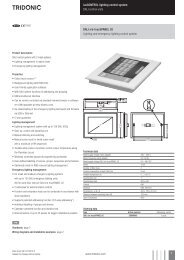
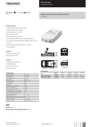
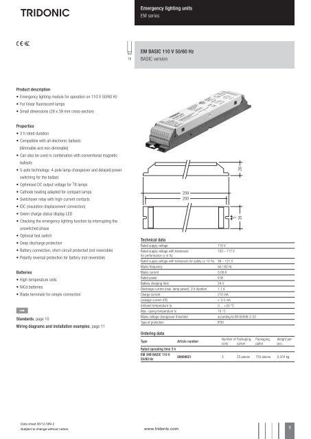
Emergency lighting units<strong>EM</strong> seriesT8<strong>EM</strong> <strong>BASIC</strong> <strong>110</strong> V <strong>50</strong>/<strong>60</strong> <strong>Hz</strong><strong>BASIC</strong> versionProduct description• Emergency lighting module for operation on <strong>110</strong> V <strong>50</strong>/<strong>60</strong> <strong>Hz</strong>• For linear fluorescent lamps• Small dimensions (28 x 39 mm cross-section)Properties• 3 h rated duration• Compatible with all electronic ballasts(dimmable and non-dimmable)• Can also be used in combination with conventional magneticballasts• 5-pole technology: 4-pole lamp changeover and delayed powerswitching for the ballast• Optimised DC output voltage for T8 lamps• Cathode heating adapted for compact lamps• Switchover relay with high-current contacts• IDC (insulation displacement connection)• Green charge status display LED• Checking the emergency lighting function by interrupting theunswitched phase• Optional test switch• Deep discharge protection• Battery connection, short-circuit protected (not reversible)• Polarity reversal protection for battery (not reversible)Batteries• High-temperature cells• NiCd batteries• Blade terminals for simple connectionÈStandards, page 10Wiring diagrams and installation examples, page 11Technical dataRated supply voltage<strong>110</strong> VRated supply voltage with tolerances103 – 117 Vfor performance (± 6 %)Rated supply voltage with tolerances for safety (± 10 %) 99 – 121 VMains frequency<strong>50</strong> / <strong>60</strong> <strong>Hz</strong>Mains current0.06 ARated power9 WBattery charging time24 hDischarge current (max. lamp power), 3 h duration 1.1 ACharge current210 mALeakage current (PE)< 0.5 mAAmbient temperature ta 0 ... +<strong>50</strong> °CMax. casing temperature tc 75 °CMains voltage changeover threshold according to EN <strong>60</strong>598-2-22Type of protectionIP20Ordering dataTypeArticle numberNumber of Packaging,cells cartonPackaging,palletWeight perpcs.Rated operating time 3 h<strong>EM</strong> 34B <strong>BASIC</strong> <strong>110</strong> V<strong>50</strong>/<strong>60</strong> <strong>Hz</strong>89899821 3 25 pieces 7<strong>50</strong> pieces 0.324 kgData sheet 06/12-589-2Subject to change without notice.www.tridonic.com 1
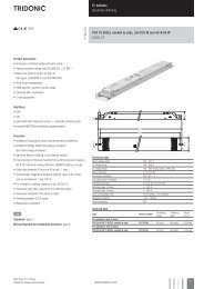
Emergency lighting units<strong>EM</strong> seriesACCESSO-RIESTest switch <strong>EM</strong>2Product description• For connection to the emergency lighting unit• For checking the device functionOrdering dataTypeArticle numberPackaging,bagPackaging,cartonWeight per pcs.Test switch <strong>EM</strong> 2 89805277 25 pieces 200 pieces 0.013 kgACCESSO-RIESStatus indication green LEDProduct description• A green LED indicates that charging current is flowing into thebatteryOrdering dataTypeArticle numberPackaging,bagPackaging,cartonWeight per pcs.LED <strong>EM</strong> green 89899<strong>60</strong>5 25 pieces 200 pieces 0.017 kgLED <strong>EM</strong> green, ultra high brightness 89899756 25 pieces 200 pieces 0.012 kgData sheet 06/12-589-2Subject to change without notice.www.tridonic.com 2
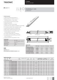
Emergency lighting units<strong>EM</strong> seriesBallast Lumen Factor (BLF) in %<strong>EM</strong> <strong>BASIC</strong> for linear lamps, 3 h3 h 4 cellsType<strong>EM</strong> 34B <strong>BASIC</strong> <strong>110</strong>VArticle no. 89899821Lamp type Wattage BLF in emergency lighting mode in % for rated operating timeT8 18 W 1330 W 1336 W 1058 W 7Technologyand capacityDesignNumber ofcellsTypeArticle no.Assignable batteriesStick 4 Accu-NiCd 4A 55 89800089 •side by side 4 Accu-NiCd 4B 89895977 •Stick + Stick 2 + 2 Accu-NiCd 4C 89895978 •Data sheet 06/12-589-2Subject to change without notice.www.tridonic.com 3
Emergency lighting units<strong>EM</strong> seriesStandards• according to EN <strong>50</strong>172• according to EN <strong>60</strong>598-2-22• EN 61347-2-7• EN <strong>60</strong>925• EN 5<strong>50</strong>15• EN 61000-3-2• EN 61000-3-3• EN 61547• EN <strong>60</strong>068-2-64• EN <strong>60</strong>068-2-29• EN <strong>60</strong>068-2-30Isolation and electric strength testing of luminairesElectronic devices can be damaged by high voltage. This has to be consideredduring the routine testing of the luminaires in production.According to IEC <strong>60</strong>598-1 Annex Q (informative only!) or ENEC 303-Annex A, eachluminaire should be submitted to an isolation test with <strong>50</strong>0 VDC for 1 second. Thistest voltage should be connected between the interconnected phase and neutralterminals and the earth terminal. The isolation resistance must be at least 2 MΩ.As an alternative, IEC <strong>60</strong>598-1 Annex Q describes a test of the electrical strengthwith 1,<strong>50</strong>0 VAC (or 1,414 x 1,<strong>50</strong>0 VDC). To avoid damage to the electronic devicesthis test must not be conducted.Batteries NiCdCase temperature range 0 °C to +55 °Cto ensure 4 years design lifeBattery voltage/cell1.2 VCapacity4.0 AhMax. short term temperature (reduced lifetime) 70 °CPacking quantity5 pcs. per cartonConnection method: 4.8 x 0.5 mm spade welded to end of cellFor the stick batteries this connection is accessible after the battery end capshave been fitted.To inhibit inverter operation, only disconnect the batteries by removing the connectorfrom the battery spade tags.Electrical connectionsAn earthed starting aid is recommended.The module should be earthed by the fixings used to attach it to the luminaire.Terminal block type:Push wire and insulation displacementTerminal block capacity• Push wire: 0.5 to 1.5 mm 2 solid conductor• Insulation displacement: 0.5 mm 2 solid conductorWire strip length: 9 to 10 mmLamp lead length: 2,<strong>50</strong>0 mm max.The longer pair of leads should always be connected to terminals 3 and 8.CE markingThe modules are CE marked for compliance with the low voltage directive.Certificates of compliance are available to allow luminaires to be CE marked forcompliance with the <strong>EM</strong>C directive.Mechanical detailsChannel manufactured from 0.4 mm Galvatite galvanised steel.Cover manufactured from 0.4 mm white precoated steel.LED status indicator• Green• Mounting hole 6.5 mm diametre• Lead length 7<strong>50</strong> mm (Bezel supplied fitted to LED)• Insulation rating: 90 °CTest switch• Mounting hole 7 mm diametre• Length of test switch lead 5<strong>50</strong> mmBattery leads• Quantity: 1 red and 1 black• Length: 1000 mm (Accu NiCd 4B, 4C), 1300 mm (all others)• Wire type: 0.5 mm 2 solid conductor• Insulation temperature rating: 90 °CTermination 1Push on 4.8 mm receptacle to suit battery spade fitted with insulating coverTermination 29 mm stripped insulationTwo-piece batteries are supplied with a 200 mm lead with 4.8 mm receptacle ateach end and insulting covers to connect the separate sticks together.Wiring guidelinesTo ensure that a luminaire containing high frequency emergency units complieswith EN 5<strong>50</strong>15 for radio frequency conducted interference in both normal andemergency mode it is essential to follow good practice in the wiring layout.Within the luminaire the switched and unswitched <strong>50</strong> <strong>Hz</strong> supply wiring must berouted as short as possible and be kept as far away as possible from the lampleads.This means, for example, in a linear T8 luminaire the mains wiring shouldbe routed along one side of the luminaire body, while the wires to the emergencylamp from the emergency module are routed along the other side.The high frequency emergency lamp wiring contains “hot” leads at pins 1 and 6,which have high voltage to earth. These should be kept as short as possible andseparated from other wiring to minimize coupling. They also have a restrictionon capacitance to other wiring and earth of 100 pF, which must be observed toensure good lamp starting.With an earth connection of the metal case of the emergency module the noisesuppression can be further improved. The wiring of the earth should be kept asshort as possible.Through wiring may affect the emc performance of the luminaire.With the use of the fifth pole possible compatibility problems between the productscan be prevented. Depending on the luminaire wiring the radio suppressionin the emergency mode of operation can be further improved.Capacitive loading limits of lamp leads must not be exceeded. Note the capacitanceof the emergency lamp leads adds to the capacitance of the leads fromthe ballast to the <strong>EM</strong> <strong>BASIC</strong> module when considering ballast loading.Service lifeAverage service life <strong>50</strong>,000 hours under rated conditions with a failure rate lessthan 10 %. Average failure rate of 0.2 % per 1,000 operating hoursData sheet 06/12-589-2Subject to change without notice.www.tridonic.com 4
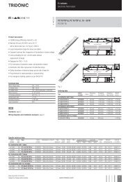
Emergency lighting units<strong>EM</strong> seriesCircuit diagramsBatt +veNeutralUn-Switched LineBatteryOrange (+)LED Pink (–)Batt -veOptional Test SwitchLinLout+NLOP-SwSw<strong>EM</strong> <strong>BASIC</strong>Emergency module87654321* hot leads Switched LineLinLout8Batt +ve+7NeutralN6Un-Switched LineBatteryL <strong>EM</strong> <strong>BASIC</strong> 5Emergency lampOrange (+)O Emergency module 4LED Pink (–)P3Batt -ve-2PFCSw1Optional Test SwitchSwSEmergency lamp*hot leadsseries capacitor circuitChokeorChokeNeutralNon maintained18 W circuit with <strong>110</strong> V magnetic control gear<strong>110</strong> V SupplySwitched LinePFCif requiredBatt +veNeutral<strong>110</strong> V Un-Switched LineBatteryOrange (+)LED Pink (–)Batt -veOptional Test SwitchLinLout+NLOP-SwSw<strong>110</strong> VMODULE87654321SEmergency lamp*hot leadsSwitched LineLoutBatt +veNeutralUn-Switched LineBatteryOrange (+)LED Pink (–)Batt -veOptional Test SwitchLinLout+NLOP-SwSw<strong>EM</strong> <strong>BASIC</strong>Emergency module87654321Emergency lamp<strong>110</strong> V BallastNeutralELECTRONICBALLASTNeutral* Hot leads36 W / 58 W circuit with <strong>110</strong> V magnetic control gear Single lamp high frequency electronic ballastData sheet 06/12-589-2Subject to change without notice.www.tridonic.com 5