
You also want an ePaper? Increase the reach of your titles
YUMPU automatically turns print PDFs into web optimized ePapers that Google loves.
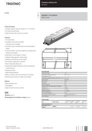
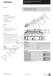
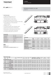
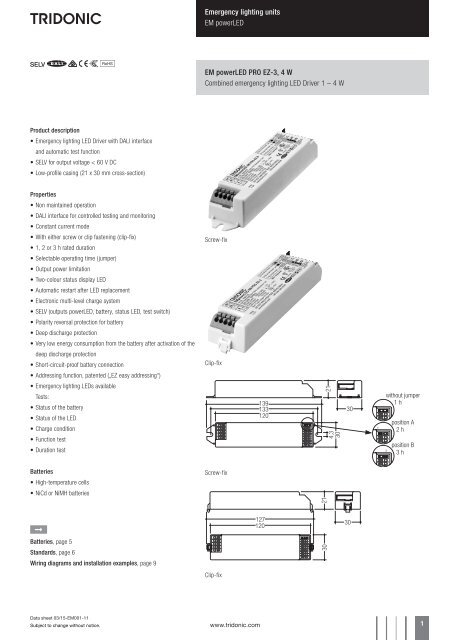
Emergency lighting units<strong>EM</strong> <strong>powerLED</strong><strong>EM</strong> <strong>powerLED</strong> <strong>PRO</strong> <strong>EZ</strong>-3, 4 WCombined emergency lighting LED Driver 1 – 4 WProduct description• Emergency lighting LED Driver with DALI interfaceand automatic test function• SELV for output voltage < 60 V DC• Low-profile casing (21 x 30 mm cross-section)Properties• Non maintained operation• DALI interface for controlled testing and monitoring• Constant current mode• With either screw or clip fastening (clip-fix)• 1, 2 or 3 h rated duration• Selectable operating time (jumper)• Output power limitation• Two-colour status display LED• Automatic restart after LED replacement• Electronic multi-level charge system• SELV (outputs <strong>powerLED</strong>, battery, status LED, test switch)• Polarity reversal protection for battery• Deep discharge protection• Very low energy consumption from the battery after activation of thedeep discharge protection• Short-circuit-proof battery connection• Addressing function, patented („<strong>EZ</strong> easy addressing“)• Emergency lighting LEDs availableTests:• Status of the battery• Status of the LED• Charge condition• Function test• Duration testScrew-fixClip-fixwithout jumperposition Aposition BBatteries• High-temperature cells• NiCd or NiMH batteriesScrew-fixÈBatteries, page 5Standards, page 6Wiring diagrams and installation examples, page 9Clip-fixData sheet 03/15-<strong>EM</strong>001-11Subject to change without notice.www.tridonic.com 1
Emergency lighting units<strong>EM</strong> <strong>powerLED</strong>Technical dataRated supply voltage220 – 240 VMains frequency50 / 60 HzTyp. λ (at 230 V, 50 Hz) 0.34Forward voltage range LED module (1 x LED)2.8 – 3.4 VForward voltage range LED module (2 x LED)5.6 – 6.8 VLED current in emergency operation (1 x LED) 1.000 mALED current in emergency operation (2 x LED) 700 mATyp. output power (1 x LED)3.4 WTyp. output power (2 x LED)4.5 WTime to light0.23 s from detection of emergency eventOvervoltage protection 320 V (for 1 h)Battery discharge current See page 5Max. casing temperature tc 70 °CAmbient temperature ta -25 ... +45 °CMains voltage changeover threshold according to EN 60598-2-22Ingress protectionIP20Ordering dataTypeArticle number Packaging,cartonPackaging,palletWeightper pc.Max. numberof LEDPowerScrew fastening version<strong>EM</strong> <strong>powerLED</strong> 4 W <strong>PRO</strong> <strong>EZ</strong>-3 89800126 25 pc(s). 600 pc(s). 0.101 kg 2 4 W<strong>EM</strong> <strong>powerLED</strong> 4W <strong>PRO</strong> <strong>EZ</strong>-3 NiMh 89800446 25 pc(s). 600 pc(s). 0.101 kg 2 4 WClip fastening version<strong>EM</strong> <strong>powerLED</strong> 4 W <strong>PRO</strong> <strong>EZ</strong>-3 89800125 25 pc(s). 600 pc(s). 0.101 kg 2 4 WSpecific technical dataTypeMains current in charging operationMains power in charging operationRated durationInitial charge Fast recharge Trickle charge 1 Initial charge Fast recharge Trickle charge 1<strong>EM</strong> <strong>powerLED</strong> 4 W <strong>PRO</strong> <strong>EZ</strong>-3 1 h 21.0 mA 27.5 mA 15.2 mA 2.0 W 3.0 W 1.2 W<strong>EM</strong> <strong>powerLED</strong> 4 W <strong>PRO</strong> <strong>EZ</strong>-3 2 h 27.5 mA 32.4 mA 21.0 mA 3.0 W 3.7 W 2.0 W<strong>EM</strong> <strong>powerLED</strong> 4 W <strong>PRO</strong> <strong>EZ</strong>-3 3 h 27.5 mA 32.4 mA 21.0 mA 3.0 W 3.7 W 2.0 W<strong>EM</strong> <strong>powerLED</strong> 4 W <strong>PRO</strong> <strong>EZ</strong>-3 NiMh 1 h 19.0 mA 24.0 mA 13.0 mA 1.7 W 2.4 W 1.0 W<strong>EM</strong> <strong>powerLED</strong> 4 W <strong>PRO</strong> <strong>EZ</strong>-3 NiMh 2 h 30.0 mA 32.0 mA 13.0 mA 3.1 W 3.3 W 1.1 W<strong>EM</strong> <strong>powerLED</strong> 4 W <strong>PRO</strong> <strong>EZ</strong>-3 NiMh 3 h 30.0 mA 32.0 mA 13.0 mA 3.1 W 3.3 W 1.1 W1For <strong>EM</strong> <strong>powerLED</strong> 4 W <strong>PRO</strong> <strong>EZ</strong>-3 NiMh: average over 20 min. (4 min. charge / 16 min. off)Data sheet 03/15-<strong>EM</strong>001-11Subject to change without notice.www.tridonic.com 2
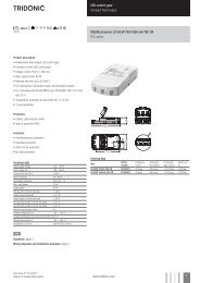
Emergency lighting units<strong>EM</strong> <strong>powerLED</strong>ACCES-SORIESTest switch <strong>EM</strong>2Product description• For connection to the emergency lighting unit• For checking the device functionOrdering dataTypeArticle numberPackaging,bagPackaging,cartonWeightper pc.Test switch <strong>EM</strong> 2 89805277 25 pc(s). 600 pc(s). 0.011 kgACCES-SORIESStatus indication bi-colour LEDProduct description• Two-colour status display LED• Green: system OK, red: faultOrdering dataTypeArticle numberPackaging,bagPackaging,cartonWeightper pc.LED <strong>EM</strong> bi-colour 89899720 25 pc(s). 200 pc(s). 0.017 kgLED <strong>EM</strong> bi-colour, high brightness 89899753 25 pc(s). 800 pc(s). 0.013 kgData sheet 03/15-<strong>EM</strong>001-11Subject to change without notice.www.tridonic.com 3
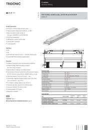
Emergency lighting units<strong>EM</strong> <strong>powerLED</strong>Product description• Provides simple addressing for the <strong>EM</strong> <strong>powerLED</strong> <strong>PRO</strong> units• Uses the bi-colour LED for the <strong>EM</strong> <strong>powerLED</strong> <strong>PRO</strong> device identification• Converts the LED binary identification signal to a DALI address ofbetween 0 to 63• The tool is powered from a 9 V battery (not supplied)ACCES-SORIESAddressing toolOrdering dataType Article number Packaging, carton Weight per pc.<strong>EM</strong> <strong>PRO</strong> addressing tool 89899836 1 pc(s). 0.08 kgData sheet 03/15-<strong>EM</strong>001-11Subject to change without notice.www.tridonic.com 4
Emergency lighting units<strong>EM</strong> <strong>powerLED</strong>Battery selection<strong>EM</strong> <strong>powerLED</strong> 4W <strong>PRO</strong> <strong>EZ</strong>-3, 1 / 2 / 3 hType<strong>EM</strong> <strong>powerLED</strong> 4W <strong>PRO</strong> <strong>EZ</strong>-3<strong>EM</strong> <strong>powerLED</strong> 4W<strong>PRO</strong> <strong>EZ</strong>-3 NiMhTechnologyand capacityDesignNumberof cellsTypeArticle no. 89800125 / 89800126 89800446Cells 5 cells 5 cellsDuration 1 h 2 / 3 h 1 h 2 / 3 hArticle no.NiCd 4 Ah stick 1 x 5 Accu-NiCd 5A 89895973 •D-cells 1 stick + stick 3 + 2 Accu-NiCd 5C 55 89800090 •NiMH 2 AhCs-CellsNiMH 4 Ah7/5 Cs-CellsAssignable batteriesstick 1 x 5 Accu-NiMh C 5A 89899703 • •side by side 5 x 1 Accu-NiMh C 5B 89899704 • •stick 1 x 5 Accu-NiMh 4 Ah C 5A 89899851 •stick + stick 2 + 3 Accu-NiMh 4 Ah C 5C 89899978 •150°C batteries also available (see seperate datasheet at www.tridonic.com)Battery charge / discharge data<strong>EM</strong> <strong>powerLED</strong> 4W <strong>PRO</strong> <strong>EZ</strong>-3, 1 / 2 / 3 hType<strong>EM</strong> <strong>powerLED</strong> 4W <strong>PRO</strong> <strong>EZ</strong>-3<strong>EM</strong> <strong>powerLED</strong> 4W<strong>PRO</strong> <strong>EZ</strong>-3 NiMhArticle no. 89800125 / 89800126 89800446Cells 5 cells 5 cellsDuration 1 h 2 / 3 h 1 h 2 / 3 hBattery chargetimeInitial charge20 hFast recharge 10 h 15 h 10 h 15 hTrickle chargecontinuouslyCharge currentInitial charge 130 mA 250 mA 130 mA 300 mAFast recharge 250 mA 330 mA 210 mA 330 mATrickle charge 60 mA 130 mA127 mA / 4 min.0 mA / 16 min.201 mA / 4 min.0 mA / 16 min.Discharge current 1,100 mA 1,100 mA 1,100 mA 1,100 mAData sheet 03/15-<strong>EM</strong>001-11Subject to change without notice.www.tridonic.com 5
Emergency lighting units<strong>EM</strong> <strong>powerLED</strong>Standards• according to EN 50172• according to EN 60598-2-22• EN 61347-2-7• EN 61347-2-13• EN 62384• EN 62034• EN 55015• EN 61000-3-2• EN 61000-3-3• EN 61547• EN 60068-2-64• EN 60068-2-29• EN 60068-2-30• EN 62386 (according to DALI standard V1)Duration link selectionDuration1 hrLink Positionwithout jumperTechnical data batteriesAccu-NiCdCase temperature rangeto ensure 4 years design life4.2 / 4.5 Ah D +5 °C to +55 °CBattery voltage/cell1.2 VCapacity D4.2 / 4.5 AhMax. short term temperature (reduced life-time) 70 °CMax. number discharge cyclesPacking quantity4 cycles per year plus4 cycles duringcomissioning5 pcs. per cartonAccu-NiMhCase temperature rangeto ensure 4 years design life2.0 Ah Cs +5 °C to +55 °C4.0 Ah Cs +5 °C to +50 °CBattery voltage1.2 VCapacity2.0 Ah / 4.0 AhMax. short term temperature (reduced life-time) 70 °CMax. number discharge cyclesPacking quantity4 cycles per year plus4 cycles duringcomissioning5 pcs. per carton2 hr3 hrposition Aposition BJumper selectionModule supplied with jumper in 3 hours position (position B).The position of the link will only be read on first power up. If it is changed afterwardsboth the battery and mains supply must be disconnected for 10 secondsto enable the <strong>EM</strong> <strong>powerLED</strong> <strong>EZ</strong>-3 to read the new link position on reconnectionof the battery and mains. It will lead to a false battery failure indication if the linkis changed after installation without this reset.Further technical dataThe <strong>EM</strong> <strong>powerLED</strong> has a unique power regulation circuit; this is designed to limitthe total power drawn from the battery in the event of using LED’s with a forwardvoltage (Vf) higher than 3.4 V.In such cases the unit will reduce the LED current in order to maintain anacceptable drain current from the battery and hence meet the required durationtime. This feature enables the <strong>EM</strong> <strong>powerLED</strong> <strong>PRO</strong> <strong>EZ</strong>-3 to have minimum batterycount for a given range of LED’s.Storage• Batteries should be stored within the specified temperature range inlow humidity conditions. Optimal storage conditions are– temperature: +5 °C to +25 °C– humidity: 65 % ±20 %• Avoid atmosphere with corrosive gas• It is recommended to disconnect the battery before store or delivery• Avoid to store the batteries discharged• A long term storage in open circuit leads to battery self discharge anddeactivation of chemical components. It could be required to charge and dischargethe batteries a few times to recover the initial performance.BatteriesConnection method: 4.8 x 0.5 mm spade tag welded to end of cellFor stick packs this connection is accessible after the battery caps have beenfitted.To inhibit inverter operation disconnect the batteries by removing the connectorfrom the battery spade tag.For battery data see separate data sheet.Data sheet 03/15-<strong>EM</strong>001-11Subject to change without notice.www.tridonic.com 6
Emergency lighting units<strong>EM</strong> <strong>powerLED</strong>Testing:DALI ControlA DALI command from a suitable control unit can be used to initiate function andduration tests at individually selected times. Status flags are set for report backand data logging of results.When a DALI bus has not been connected or when a DALI bus is connected butthe DALI default DELAY and INTERVAL times have not been re-set by sendingappropriate DALI commands, then the <strong>EM</strong> <strong>powerLED</strong> <strong>PRO</strong> <strong>EZ</strong>-3 will conductself-tests in accordance with the default times set within the EE<strong>PRO</strong>M . Thesedefault times are factory pre-set, in accordance with the DALI standard EN62386-202, to conduct an automatic function test every 7 days and a durationtest every 52 weeks. Since the DELAY time is factory pre-set to Zero, all unitsare tested at the same time. Test times can be changed with a command overthe DALI bus.The DELAY and INTERVAL time values must be re-set when the emergency systemtest times are to be scheduled by a DALI control and monitoring system.Note that once the default values have been set to Zero, tests will only be conductedfollowing a command from the control system. If the DALI bus is disconnectedthe <strong>EM</strong> <strong>powerLED</strong> <strong>PRO</strong> <strong>EZ</strong>-3 does not revert to self-testing mode.AddressingThe <strong>EM</strong> <strong>powerLED</strong> <strong>PRO</strong> <strong>EZ</strong>-3 includes the new <strong>EZ</strong> easy addressing system whichallows addressing and identification by using the bi-colour LED in conjunctionwith the <strong>EM</strong> <strong>PRO</strong> addressing tool. Binary address codes given by the LED can besimply converted to the DALI addresses 0 to 63. For single handed addressingusing this method it is necessary to send a broadcast ident command every 3to 9 seconds. During this command the main fluorescent lamp will be switchedoff and the LED will flash the 6 bit binary address preceded by a 3 second startindication period.CommissioningAfter installation of the luminaire and initial connection of the mains supply andbattery supply to the <strong>EM</strong> <strong>powerLED</strong> <strong>PRO</strong> <strong>EZ</strong>-3 the unit will commence chargingthe batteries for 20 hours (initial charge). Afterwards the module will conduct acommissioning test for the full duration. The 20 hours recharge occurs also if anew battery is connected or the module exits the rest mode condition. The followingautomatic commissioning duration test is only performed when a batteryis replaced and fully charged (after 20 hrs) and the interval time is not set tozero, otherwise the system is expected to perform the testing.Functional testThe time of day and frequency of the 5 seconds function test can be set by theDALI controller. The default setting is a 5 seconds test on a weekly basis.Duration testThe time of day and frequency of the duration test can be set by the DALIcontroller. The default setting is a duration test conducted every 52 weeks.DALI ControllerDALI controllers and hardware/software solutions are available from <strong>Tridonic</strong>.Please refer to the Lighting controls section.Life-timeAverage life-time 50,000 hours under rated conditions with a failure rate of lessthan 10 %. Average failure rate of 0.2 % per 1000 operating hours.Isolation and electric strength testing of luminairesElectronic LED Drivers can be damaged by high voltage. This has to be consideredduring the routine testing of the luminaires in production.According to IEC 60598-1 Annex Q (informative only!) or ENEC 303-Annex A, eachluminaire should be submitted to an isolation test with 500 VDC for 1 second. Thistest voltage should be connected between the interconnected phase and neutralterminals and the earth terminal. The isolation resistance must be at least 2 MΩ.As an alternative, IEC 60598-1 Annex Q describes a test of the electrical strengthwith 1,500 VAC (or 1,414 x 1,500 VDC). To avoid damage to the electronic devicesthis test must not be conducted.Status indicationSystem status is indicated by a bi-colour LED and by a DALI status flag.LED indiction Status KommentarPermanent green System OK AC modeFast flashing green(0,1 sec on – 0,1 sec off)Slow flashing green(1 sec on – 1 sec off)Function testunderwayDuration testunderwayRed LED on Load failure Open circuit / Short circuit / LED failure 1Slow flashing red(1 sec on – 1 sec off)Fast flashing red(0,1 sec on – 0,1 sec off)Battery failure Battery failed the duration test or function /Battery is defect / Incorrect battery voltageCharging failure Incorrect charging currentDouble pulsing green Inhibit mode Switching into inhibit mode via controllerBinary transmission of addressvia green/red LEDAddressidentificationDuring address identification modeGreen and red off DC mode Battery operation (emergency mode)1 If the <strong>EM</strong> <strong>powerLED</strong> is operated in non-maintained mode and an LED fault is detected, the redindicator LED will be illuminated and the output will be stopped. The unswitched mains supplymust be switched off before the LED is changed in order that the new LED can be detected. Afunction or duration test will not reset the fault indication.Prolong timeProlong time can be set by the DALI controller. This is the delay time betweenreturn of the mains supply and the end of the emergency operation. The defaultprolong time is set as 0 minutes as specified within the DALI standard.Indicator LED will stay off for the duration of the prolong time.Rest ModeRest mode can be initiated by the DALI controller. The appropriate commandshould be sent after the mains supply has been disconnected and whilst themodule is in emergency operation. A mains reset is required to exit the restmode. <strong>EM</strong> <strong>powerLED</strong> <strong>PRO</strong> <strong>EZ</strong>-3 does support the re-light command via the DALIbus.Test switchAn optional test switch can be wired to each <strong>EM</strong> <strong>powerLED</strong> <strong>PRO</strong> <strong>EZ</strong>-3. This canbe used to initiate a 5 seconds function test by a short press < 1 second.Data sheet 03/15-<strong>EM</strong>001-11Subject to change without notice.www.tridonic.com 7
Emergency lighting units<strong>EM</strong> <strong>powerLED</strong>Mechanichal detailsCase manufactured from polycarbonate.Glow-wire test according to EN 61347-1 with increased temperature of 850 °Cpassed.LED bi-colour status indicator• Green / red• Mounting hole 6.5 mm dia• Lead length 1,000 mm• Insulation rating: 90 °CTest switch• Mounting hole 7.0 mm dia• Lead length 550 mmBattery leads• Quantity: 1 red and 1 black• Length: 1,300 mm• Wire type: 0.5 mm 2 solid conductor• Insulation rating: 90 °CBattery end terminationPush on 4.8 mm receptacle to suit battery spade fitted with insulating coverWiring type and cross sectionWiringmains (SL, N, L)LED (LED +, LED –)Wiringbatteries (Bat +, Bat –)test switch (switch)status indication LED (status K, A)Use one wire for each terminal connector only.Max. lead insulation diameterBattery2.1 mmTest switch2.1 mmIndicator LED2.1 mm0.5 – 1.5 mm² solid or fine-stranded0.5 – 1.0 mm² fine-stranded with ferrule8.5 – 9.5 mm0.2 – 0.5 mm² solid or fine-stranded0.25 mm² fine-stranded with ferrule8.5 – 9.5 mmModule end termination8.0 mm stripped insulationTwo-piece batteries are supplied with a 200 mm lead with 4.8 mm receptacles ateach end and insulating covers to connect the separate sticks together.Maximum lead lengthLEDstatus indication LEDbatteries3 m1 m1 mRecommended fixing details for clip fixing125,20,4 mm to 0,6 mm thick gear trayfixing slots4,3 x 9,3 mmRelease of the wiringPress down the “push button” and removethe cable from front.122,40,6 mm to 1,1 mm thick gear trayMaximum loading of automatic circuit breakersAutomatic circuit breaker type B10 B13 B16 B20 Inrush currentInstallation Ø 1.5 mm 2 1.5 mm 2 2.5 mm 2 2.5 mm 2 I maxTime<strong>EM</strong> <strong>powerLED</strong> 4 W <strong>PRO</strong> <strong>EZ</strong>-3 90 130 130 130 10 A 120 μs<strong>EM</strong> <strong>powerLED</strong> 4 W <strong>PRO</strong> <strong>EZ</strong>-3 NiMh 90 130 130 130 10 A 120 μsData sheet 03/15-<strong>EM</strong>001-11Subject to change without notice.www.tridonic.com 8
Emergency lighting units<strong>EM</strong> <strong>powerLED</strong>Wiring diagramsWiring diagram for one LED or two LED in seriesDALI controlDALI controlNeutralPermanent lineDADANL<strong>EM</strong> <strong>powerLED</strong> <strong>PRO</strong>status Astatus KswitchswitchLED +LED –Bat –Bat +orangepinkLEDOptionalTest Switch+ – + –LEDBatteryWiring diagram for multiple LED (3–12) in parallelDALI controlDALI controlNeutralPermanent lineDADANL<strong>EM</strong> <strong>powerLED</strong> <strong>PRO</strong>status Astatus KswitchswitchLED +LED –Bat –Bat +orangepinkLEDOptionalTest SwitchLED+ – +–+ – + –BatteryTake care that the LED is connected with the right polarity.LED that are connected to the <strong>EM</strong> <strong>powerLED</strong> <strong>PRO</strong> <strong>EZ</strong>-3 devices should have areverse polartity protection device such as a schottky diodes fitted, otherwiseirreversible damage could occur if the LED is connected in reverse polarity. Anyprotection device must be capaple of handling in excess of 1,000 mA.Note: Please ensure that at the terminal of the <strong>EM</strong> <strong>powerLED</strong> module the batterynegative is not connected to the negative of the LED load.Wiring diagram with LED DriverManually tested emergency lighting with combined LED modules forgeneral and emergency lighting (e.g. STARK QLE CLASSIC <strong>EM</strong>,STARK LLE 24-280-1250 <strong>EM</strong>, STARK CLE CLASSIC <strong>EM</strong>,STARK SLE CLASSIC <strong>EM</strong>):Due to the fact that independent circuits are used for general and emergencylighting it is important that the normal supply of the mains LED Driver is switchedoff together with the permanent emergency supply prior to checkingthe operation of the emergency LEDs.If this is not done then it may not be possible to see that the emergency LEDsare operating.Use a circuit similar to that shown next.220–240 V50/60 HzLNPETest Switch*Light SwitchDADANLPENL<strong>EM</strong> <strong>powerLED</strong> <strong>PRO</strong>LEDmains control gearstatus Astatus KswitchswitchLED +LED –Bat –Bat +LED +LED –orangepinkLEDOptionalTest SwitchBattery+ <strong>EM</strong>- <strong>EM</strong>+-LED Module* Use 230 V Test switchData sheet 03/15-<strong>EM</strong>001-11Subject to change without notice.www.tridonic.com 9
Emergency lighting units<strong>EM</strong> <strong>powerLED</strong>Wiring instructions• The <strong>powerLED</strong> terminals, battery, indicator LED and test switch terminals areclassified as SELV. Keep the wiring of the DALI and the input terminals separatedfrom the wiring of the SELV terminals or consider special wiring (doubleinsulation, 6 mm creepage and clearance) when these connections should bekept SELV.• The output to the LED is DC but has high frequency content at 125 kHz, whichshould be considered for good <strong>EM</strong>C compliance.• <strong>powerLED</strong> leads should be separated from the mains and DALIconnections and wiring for good <strong>EM</strong>C performance. With some luminaires itmay be necessary to add a ferrite bead inductor to obtain satisfactory <strong>EM</strong>Cperformance.• Maximum lead length on the <strong>powerLED</strong> terminals is 3 m. For a good<strong>EM</strong>C performance keep the LED wiring as short as possible.• Maximum lead length for the Test switch and Indicator LED connectionis 1 m. The test switch and Indicator LED wiring should be separatedfrom the <strong>powerLED</strong> leads to prevent noise coupling.• Battery leads are specified with 0.5 mm 2 cross section and a lengthof < 1.3 m• DALI terminals are mains proof.i For comprehensive instructions consult the <strong>Tridonic</strong>website www.tridonic.comData sheet 03/15-<strong>EM</strong>001-11Subject to change without notice.www.tridonic.com 10