The DatasheetArchive - Datasheet Search Engine
The DatasheetArchive - Datasheet Search Engine
The DatasheetArchive - Datasheet Search Engine

Create successful ePaper yourself
Turn your PDF publications into a flip-book with our unique Google optimized e-Paper software.
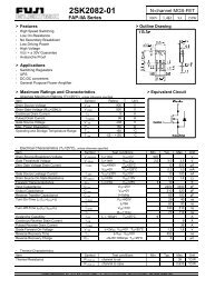
Product SpecificationLow Cost Green-Mode PWM Controller for Flyback ConvertersSG6848MARKING DIAGRAMSPIN CONFIGURATION1MAYWWSOT-26M: Mask VersionY: Year; WW: Work Week GNDFBRI123654GATEVDDSENSE8DIP-8SG6848DXXXXXXXYYWWVXXXXXXX: Wafer LotYY: Year; WW: WeekV: Assembly LocationGATEVDD1287GNDFBNC36NC1SENSE45RIORDERING INFORMATIONPart Number PWM Frequency PackageSG6848T 70kHz 6-Pin SOT-26SG6848D 70kHz 8-pin DIP-8PIN DESCRIPTIONSPin No.NameTypeDIP-8 / (SOT-26)FunctionGATE 1 / (6) Driver Output <strong>The</strong> totem-pole output driver for driving the power MOSFET.VDD 2 / (5) Supply Power supply.NC 3 NC pin.SENSE 4 / (4) Analog InputCurrent sense. This pin senses the voltage across a resistor. When the voltage reachesthe internal threshold, PWM output is disabled. This activates over-current protection.This pin also provides current amplitude information for current-mode control.A resistor connected from the RI pin to ground will generate a constant current source forRI 5 / (3)the SG6848. This current is used to charge an internal capacitor, to determine theAnalogswitching frequency. Increasing the resistance will reduce the amplitude of the currentInput/Outputsource and reduce the switching frequency. A 95kΩ resistor R i results in a 50uA constantcurrent I i and a 70kHz switching frequency.NC 6 NC pin.FB 7 / (2) Analog InputFeedback. <strong>The</strong> FB pin provides the output voltage regulation signal. It provides feedbackto the internal PWM comparator, so that the PWM comparator can control the duty cycle.GND 8 / (1) Supply Ground.© System General Corp. - 2 - www.sg.com.twVersion 1.2(IRO33.0010.B0) May.06, 2003
Product SpecificationLow Cost Green-Mode PWM Controller for Flyback ConvertersSG6848RECOMMENDED OPERATING CONDITIONSSymbol Parameter Value UnitV DD DC Supply Voltage ≦20 VT a Operating Ambient Temperature -30 to +85 ℃ELECTRICAL CHARACTERISTICS (T A = 25°C, VDD=15V)Feedback Input SectionSymbol Parameter Test Condition Min. Typ. Max. UnitI oz Zero Duty Cycle Input Current 1.3 2.0 mAV op Open Loop Voltage 4.5 VCurrent Sense SectionSymbol Parameter Test Condition Min. Typ. Max. UnitZ cs Input Impedance 10 kΩT PD Delay to Output 150 200 nsecV TH,FLT Current Limit Flatten Threshold Voltage 1.0 VV TH,VALLEY Current Limit Valley Threshold Voltage 0.80 0.85 0.90 VOscillator SectionSymbol Parameter Test Condition Min. Typ. Max. UnitF osc Frequency R I=95kΩ 65 70 75 kHzF osc-green Green-Mode Frequency R I=95kΩ 13 15 kHzI g Green-Mode FB Input Current 1.16 mAI nGreen-Mode Start Threshold FB Input CurrentI n = 0.3mA for a Maximum Duty Cycle1 mAS g Green-Mode Modulation Slope R I=95kΩ 300 Hz/uAF dv Frequency Variation versus V DD Deviation V DD=12 to 20V 0.02 2 %F dt Frequency Variation versus Temp. Deviation T A=-30 to 85 ℃ 2 %PWM SectionSymbol Parameter Test Condition Min. Typ. Max. UnitDC (MAX) Maximum Duty Cycle 70 75 80 %DC (MIN) Minimum Duty Cycle - 1 2 %Bnk Leading-Edge Blanking Time 250 nsecOutput SectionSymbol Parameter Test Condition Min. Typ. Max. UnitV ol Output Voltage Low V DD=15V, I o=20mA 1.5 VV oh Output Voltage High V DD=15V, I o=20mA 8 Vt r Rising Time V DD=15V, C L=1nF 50 200 nsect f Falling Time V DD=15V, C L=1nF 30 150 nsecV CLAMP Output Clamp Voltage V DD=20V 15 17 V© System General Corp. - 4 - www.sg.com.twVersion 1.2(IRO33.0010.B0) May.06, 2003
Product SpecificationLow Cost Green-Mode PWM Controller for Flyback ConvertersSG6848Under Voltage Lockout SectionSymbol Parameter Test Condition Min. Typ. Max. UnitV TH(ON) Start Threshold Voltage T A=25°C 15.3 16.3 17.3 VV DD(min) Min. Operating Voltage T A=25°C 10.9 11.7 12.5 VTotal Standby Current SectionSymbol Parameter Test Condition Min. Typ. Max. UnitI DD ST Start-up Current V DD=15V 5 30 uAI DD OP Operating Supply Current V DD=15V 2 5 mA© System General Corp. - 5 - www.sg.com.twVersion 1.2(IRO33.0010.B0) May.06, 2003
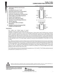
Product SpecificationLow Cost Green-Mode PWM Controller for Flyback ConvertersSG6848TYPICAL CHARACTERISTICS17.016.5Start-up Threshold Voltage (VTH(ON)) vsTemperature12.212.011.8Min. Operating Voltage (VDD (min)) vsTemperatureVTH(ON) (V)16.015.5VDD (min) (V)11.611.411.215.011.010.814.5-40 -25 -10 5 20 35 50 65 80 95 110 125TEMPERATURE (℃ )10.6-40 -25 -10 5 20 35 50 65 80 95 110 125TEMPERATURE (℃ )30Start-up Crrent (IDD ST) vs Tem peraturePWM Oscillator Frequency (FOSC) vsTemperatureIDD ST (uA)252015105FOSC (KHz)74.072.571.069.568.066.50-40 -25 -10 5 20 35 50 65 80 95 110 125TEMPERATURE (℃ )65.0-40 -25 -10 5 20 35 50 65 80 95 110 125TEMPERATURE (℃ )FOSC-green (KHz)15141312111098Frequency in green mode (FOSC-green)vs Temperature-40 -25 -10 5 20 35 50 65 80 95 110 125TEMPERATURE (℃ )DC (MAX) (%)8079787776757473727170Max. Duty Cycle (DC(MAX)) vsTemperature-40 -25 -10 5 20 35 50 65 80 95 110 125TEMPERATURE (℃ )© System General Corp. - 6 - www.sg.com.twVersion 1.2(IRO33.0010.B0) May.06, 2003
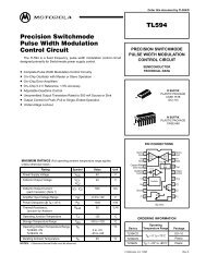
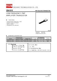
Product SpecificationLow Cost Green-Mode PWM Controller for Flyback ConvertersSG6848807060PWM Oscillator Frequency (FOSC) vs.FBFOSC (KHz)504030201000.6 0.7 0.8 0.9 1.0 1.1 1.2 1.3 1.4FB (mA)© System General Corp. - 7 - www.sg.com.twVersion 1.2(IRO33.0010.B0) May.06, 2003
Product SpecificationLow Cost Green-Mode PWM Controller for Flyback ConvertersSG6848OPERATION DESCRIPTIONSG6848 devices integrate many useful designs intoone controller for low-power switch-mode power supplies.<strong>The</strong> following descriptions highlight some of the featuresof the SG6848 series.Start-up Current<strong>The</strong> start-up current is only 5uA. Low start-upcurrent allows a start-up resistor with a high resistanceand a low-wattage to supply the start-up power for thecontroller. A 1.5 MΩ, 0.25W, start-up resistor and a10uF/25V V DD hold-up capacitor would be sufficient foran AC-to-DC power adapter with a wide input range(100V AC to 240V AC ).Operating Current<strong>The</strong> operating current has been reduced to 2mA. <strong>The</strong>low operating current results in higher efficiency andreduces the V cc hold-up capacitance requirement.Green-Mode Operation<strong>The</strong> proprietary green-mode function providesoff-time modulation to linearly decrease the switchingfrequency under light-load conditions. On-time is limitedto provide stronger protection against brownouts andother abnormal conditions. <strong>The</strong> feedback current, which issampled from the voltage feedback loop, is taken as thereference. Once the feedback current exceeds thethreshold current, the switching frequency starts todecrease. This green-mode function dramatically reducespower consumption under light-load and zero-loadconditions. Power supplies using the SG6848 can easilymeet even the strictest regulations regarding standbypower consumption.Oscillator OperationA resistor connected from the RI pin to ground willgenerate a constant current source for the SG6848. Thiscurrent is used to charge an internal capacitor. <strong>The</strong>charge-time determines the internal clock speed and theswitching frequency. Increasing the resistance will reducethe amplitude of the input current and reduce theswitching frequency. A 95kΩ resistor R i results in a 50uAconstant current I i and a 70kHz switching frequency. <strong>The</strong>relationship between R i and the switching frequency is:fPWM6650= (kHz )RI(kΩ)<strong>The</strong> range of the oscillation frequency is designed tobe within 50kHz ~ 100kHz.Leading-Edge BlankingEach time the power MOSFET is switched on, aturn-on spike will inevitably occur at the sense-resistor.To avoid premature termination of the switching pulse, a250 nsec leading-edge blanking time is built in.Conventional RC filtering can therefore be omitted.During this blanking period, the current-limit comparatoris disabled and it cannot switch off the gate driver.Constant Output Power LimitWhen the SENSE voltage across the sense resistor R sreaches the threshold voltage (around 1.0V), the outputGATE drive will be turned off following a shortpropagation delay t D . This propagation delay willintroduce an additional current proportional to t D *V in /L p .<strong>The</strong> propagation delay is nearly constant regardless of theinput line voltage V IN . Higher input line voltages willresult in larger additional currents. At high input linevoltages, the output power limit will be higher than at lowinput line voltages.To compensate for this output power limit variationacross a wide AC input range, the threshold voltage isadjusted by adding a positive ramp. This ramp signal risesfrom 0.85V to 1.0V, and then flattens out at 1.0V. Asmaller threshold voltage forces the output GATE drive toterminate earlier. This reduces the total PWM turn-ontime and makes the output power equal to that of low lineinput. This proprietary internal compensation ensures aconstant output power limit for a wide AC input voltagerange (90VAC to 264VAC).© System General Corp. - 8 - www.sg.com.twVersion 1.2(IRO33.0010.B0) May.06, 2003
Product SpecificationLow Cost Green-Mode PWM Controller for Flyback ConvertersSG6848Under Voltage Lockout (UVLO)<strong>The</strong> turn-on and turn-off thresholds of the SG6848are fixed internally at 16.3V/11.7V. During start-up, thehold-up capacitor must be charged to 16.3V through thestart-up resistor, so that the SG6848 will be enabled. <strong>The</strong>hold-up capacitor will continue to supply V DD until powercan be delivered from the auxiliary winding of the maintransformer. V DD must not drop below 11.7V during thisstart-up process. This UVLO hysteresis window ensuresthat hold-up capacitor will be adequate to supply V DDduring start-up.Gate Output<strong>The</strong> SG6848 BiCMOS output stage is a fast totempole gate driver. Cross conduction has been avoided tominimize heat dissipation, increase efficiency, andenhance reliability. <strong>The</strong> output driver is clamped by aninternal 15V Zener diode in order to protect powerMOSFET transistors against undesired over-voltage gatesignals.Built-in Slope Compensation<strong>The</strong> sensed voltage across the current sense resistoris used for current mode control and pulse-by-pulsecurrent limiting. Built-in slope compensation willimprove stability and prevent sub-harmonic oscillationsdue to peak-current mode control. <strong>The</strong> SG6848 has asynchronized, positively-sloped ramp built-in at eachswitching cycle. <strong>The</strong> slope of the ramp is:0.33× DutyDuty(max)Noise ImmunityNoise from the current sense or the control signal cancause significant pulse width jitter, particularly incontinuous-conduction mode. While slope compensationhelps alleviate these problems, further precautions shouldstill be taken. Good placement and layout practices shouldbe followed. Avoiding long PCB traces and componentleads, locating compensation and filter components nearthe SG6848, and increasing the power MOS gateresistance is advised.© System General Corp. - 9 - www.sg.com.twVersion 1.2(IRO33.0010.B0) May.06, 2003
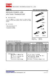
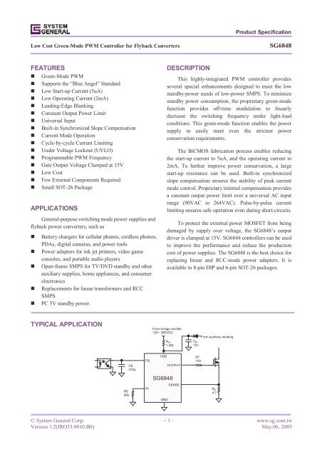
Product SpecificationLow Cost Green-Mode PWM Controller for Flyback ConvertersSG6848REFERENCE CIRCUITCircuitLNF1CX1C62 - + 4U11GND GATE62FB VDD53RI SENSE4R913BD1L11 2C1+C2R12 1R29D1R1085R71Q17 3,4R6R8 D21 2+C423C3R5R3R410T11,2D42 1R11C7C8+L21 22 1D5+C9VOGND4U21R1332R14CY13U31C10R122BOMReference Component Reference ComponentBD1 BD 1A/500V L2 10uH 6mmCX1 (Optional) YC 472P/400V (Y1) Q1 MOSFET 1A/600VCY1 (Optional) YC 102P/400V (Y1) R1,R2 R 750KΩ 1206C2 EC 10uF/400V 105℃ R4,R3 R 47KΩ 1206C1 CC 103P/500V R5 R 47Ω 1206C3 CC 1000P/500V R6 R 4.7Ω 1206C4 EC 10u/50V R7 R 100Ω 0805C6 CC 472P 0805 R8 R 10Ω 1206C7 (Optional) CC 102P/100V 1206 R10 (Optional) R 10Ω 1206C8 EC 470u/10V 105℃ R9 R 100KΩ 0805C9 EC 220u/10V 105℃ R11 R 100Ω 1/8WC10 CC 222P 0805 R12 R 33KΩ 0805D1 Diode FRI07 R13 R 33KΩ 1/8WD2 Diode FR102 R14 R 4.7KΩ 0805D4 Diode SB360 T1 EE-16D5 (Optional) ZD 6.8V 0.5W U1 IC SG6848 (Green PWM IC)F1 R 1Ω/0.5W U2 PC817L1 20mH 6*8mm U3 TL431© System General Corp. - 10 - www.sg.com.twVersion 1.2(IRO33.0010.B0) May.06, 2003
Product SpecificationLow Cost Green-Mode PWM Controller for Flyback ConvertersSG6848PACKAGE INFORMATION8 PINS -- DIP (D)D8 5Θ °E1EeB14A1A2ALb1beDimensionsMillimetersInchesSymbolMin. Typ. Max. Min. Typ. Max.A 5.334 0.210A1 0.381 0.015A2 3.175 3.302 3.429 0.125 0.130 0.135b 1.524 0.060b1 0.457 0.018D 9.017 9.271 10.160 0.355 0.365 0.400E 7.620 0.300E1 6.223 6.350 6.477 0.245 0.250 0.255e 2.540 0.100L 2.921 3.302 3.810 0.115 0.130 0.150e B 8.509 9.017 9.525 0.335 0.355 0.375θ˚ 0˚ 7˚ 15˚ 0˚ 7˚ 15˚© System General Corp. - 11 - www.sg.com.twVersion 1.2(IRO33.0010.B0) May.06, 2003
Product SpecificationLow Cost Green-Mode PWM Controller for Flyback ConvertersSG6848SOT-26 (S)bD6 4Detail AEE11 e3ce1θ1R1RL2AA1A2θ1LL1θDimensionsDetail AMillimetersInchesSymbolMin. Typ. Max. Min. Typ. Max.A 1.45 0.057A1 0.15 0.006A2 0.90 1.15 1.30 0.036 0.045 0.051b 0.30 0.50 0.011 0.020c 0.08 0.22 0.003 0.009D 2.90 0.114E 2.80 0.110E1 1.60 0.063e 0.95 0.037e1 1.90 0.075L 0.30 0.45 0.60 0.020 0.018 0.024L1 0.60 0.024L2 0.25 0.010R 0.10 0.004R1 0.10 0.25 0.004 0.010θ˚ 0˚ 4˚ 8˚ 0˚ 4˚ 8˚θ1˚ 5˚ 10˚ 15˚ 5˚ 10˚ 15˚© System General Corp. - 12 - www.sg.com.twVersion 1.2(IRO33.0010.B0) May.06, 2003
Product SpecificationLow Cost Green-Mode PWM Controller for Flyback ConvertersSG6848DISCLAIMERSLIFE SUPPORTSystem General’s products are not designed to be used as components in devices intended to support or sustainhuman life. Use of System General’s products in components intended for surgical implant into the body, or otherapplications in which failure of System General’s products could create a situation where personal death or injury mayoccur, is not authorized without the express written approval of System General’s Chief Executive Officer. SystemGeneral will not be held liable for any damages or claims resulting from the use of its products in medical applications.MILITARYSystem General's products are not designed for use in military applications. Use of System General’s products inmilitary applications is not authorized without the express written approval of System General’s Chief Executive Officer.System General will not be held liable for any damages or claims resulting from the use of its products in militaryapplications.RIGHT TO MAKE CHANGESSystem General reserves the right to change this document and/or this product without notice. Customers are advisedto consult their System General sales representative before ordering.© System General Corp. - 13 - www.sg.com.twVersion 1.2(IRO33.0010.B0) May.06, 2003