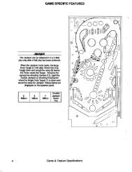
Atari Airborne Avenger Manual - Mame channel
Atari Airborne Avenger Manual - Mame channel
Atari Airborne Avenger Manual - Mame channel

Create successful ePaper yourself
Turn your PDF publications into a flip-book with our unique Google optimized e-Paper software.
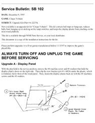
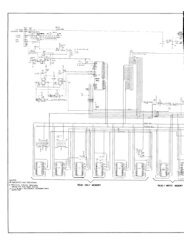
On Match/Credit Display PCB, place meter's ground lead on "plus" side of C2; other lead placed on "pIus" side of C1 gives +90 voltsreading, and on "minus" side of C2 gives -90 volts reading.On Score Panel PCB, place ground lead on "plus" side of C2; other lead on "plus" side of C1 gives +90 volts reading, and on "minus"side of C2 gives -90 volts reading.4. If one or more readings are low (or at zero volts), check each PCB separately as follows. Disconnect J19 and re-measure the voltages onthe Score PCB. If the voltages are OK, then some portion of the circuitry on the Match/Credit Display PCB is pulling down the supplyvoltages. If the voltages are still incorrect, reconnect J19, disconnect J17, and re-measure the voltages on the Match/Credit DisplayPCB. If voltages are OK, then some portion of the circuitry on the Score Display PCB is pulling down the supply voltages.If the voltages remained incorrect while each board was checked separately, leave J17 and J19 both disconnected. Then check the +90volt and -90 volt outputs on the Auxiliary PCB (where the high voltage power supply circuitry is located). These 90-volt supplyvoltages must both be present on each display PCB before the displays can light up.If all voltage readings on the display PCBs are within 5% of the correct values, then go on to the next portion of the procedure.Figure 16: Top View of Score and Match/Credit Display AssemblyScore Panel Removal and Visual ChecksAfter the +90 volt and -90 volt supply voltages have been verified, the next troubleshooting step on the score panel will be to remove it fromconnector J21.1. Turn off AC power to the game, preferably by pulling out the power plug from the wall outlet.2. Remove the metal clips holding the score panel onto the bracket arms of J21 (refer to Figure 17).WARNING: Glass edges of score panel may be sharp. Use caution to prevent cutting your hands.3. Using your right band, grasp the right edge of the score panel. Carefully lift it up approximately 1/4-inch, and then pull it straight outand remove it completely.4. Examine the positions of the terminal pins on J21. Tips of the pins should be aligned in the same plane, as shown in the detail view ofFigure 17. If not bent out of alignment, all pins can then make contact with the score panel's terminal strips when the panel is pluggedin.