Operations Manual
Operations Manual
Operations Manual
- No tags were found...

You also want an ePaper? Increase the reach of your titles
YUMPU automatically turns print PDFs into web optimized ePapers that Google loves.
ELECTRONICS DAMEEJ, INC.<br />
October 1993<br />
16-50023-1 01<br />
THE REXT liERERiJTIDR<br />
TM<br />
OPERATIONS MANUAL<br />
<strong>Operations</strong> & Adjustments o Testing & Problem Diagnosis<br />
Parts Information o Wiring Diagrams & Schematics<br />
Williams Electronics Games, Inc.<br />
3401 N.California<br />
Chicago, II 60618
I (30}<br />
I (32i<br />
ROM Jumper Chartr:-----..---<br />
11 M I 2M I 4M ROM I W1 ~2<br />
In ut<br />
Country DIP Switch Chart<br />
Sw4 Sw5 Sw6 Sw7 Sw8<br />
American On On On On On<br />
l=t On On Off On On<br />
French On On On Off Off<br />
German On On On On Off<br />
S_partl~b _ On Off On<br />
~-··~~~<br />
-- ·--·<br />
On On<br />
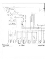
SOLENOID I FLASHER TABLE<br />
SOl.<br />
No.<br />
Function<br />
Solenoid<br />
Type<br />
Voltage Connections Drive Drive Connections Drive i>olenoid Part Number<br />
xiste Wire Rashlamp Type<br />
Playtleld Beckbox Cebinet Pleyfield Beokbox Cabinet Color Playfield Baokbox<br />
n1· oltf.lllnllil"loW7-3 Bm-Red AE- 1200<br />
11 rrouoh LowPower J107-2 (li;A 1127-4 Bm-Orn IAE- 1500<br />
,., ~af1Ja1BumMr LowPower J107-2 l'l!i J127-5 Bm-Yel AE- 1200<br />
13 RiohtJetBumMr LowPower J107-2 I"F..l J127-6 Bm-Grn AE-26-1200<br />
14 Low Power J107·2 n4A 127-7 Bm-Biu AE-26-1200<br />
Hi TooOivenor LowPower J107-2 Cl4R J127-8 Brn-Vio AE-25-1000<br />
18 Bora Kicker Low Power J107-2 rl4A J127-9 Brn-Gr¥ Al-23-800<br />
17 LafiGunUotor LowPower J118-2 c:\4 J126-1 Blk-Brn A-17562<br />
til Riaht Gun Motor Low Power J118-2 Cl4o J126-2 Blk-Red A-17562<br />
19 Not Used ~ Blk-Qra<br />
Rasher J107-6 J126-4 Blk-Yel 189 11<br />
her Rasher J1()7-6 J1 06-5 J126·5 J125-6 Blu-Gm 189 1} 1906 (1}<br />
~h~er+F1Ras~he~r~~~J1~0~~~6-r~~--+------+~~~J1~26~-6~~~~-+------~B~Iu~-B~Ik~~l89~1~(2~2)~~~~<br />
Rasher J107-6 J106-5 J126-7 J125-8 Blu-VIO 1906 (3) 1906 (1)<br />
Flasher 107-6 ~~~ J126-8 Blu-GiY 1906 1}<br />
25 I Exit Un. Gnd. Flashe ien. u se 107- J106-5 )::>6 J122·1 J124-1 I Blu-Bm 189 (1) 1906 (1}<br />
-<br />
26 Right Bor 1 Flasher ien. u ISil 1107- J1 06-5 :!24 J122-2 J124-2 Blu-Red 1906 2) 1906(1}<br />
27 Left BO lasher en. ur se 1101- J1 06-5 022 J122-3 J124-3 Blu-Org 1906 (2) 1906(1)<br />
28 enter wg Flasner ien. PUI se 1101- J106-5 020 J122-4 J124-5 Blu-Yel 1906 (2) M906 (1}<br />
19-36 11 Fll r Circuii/S<br />
37" nder ertor Top I Low Power J1 07- 016 J4-2 811-Wht IAE-2:1-1000<br />
38' nder ertor BOt 1 LOW Power J1 01- 015 J4-4 Bl ~-Wht I AE-2:1-1 uuu<br />
39' opt IUp ILOWI'Ower J1U/· 014 J4-5<br />
40' op [ op DoWn 1 LOW I"Ower JlU ,_ 013 J4-6<br />
41' RomuanFJasners ILOWPower J107-6 J106-5 09 J3-2 J3-2 Grn-Wht I ~~\~Uti ( 1) 1906 (1)<br />
42' HtgntHampFiasllei'SILOW t"Ower JlUI-t:i J106-5 010 JJ-3 J3-3 Btu-wnt 1189 1 ll\!00 (11<br />
*Not•: Controlled from the 8·Driver Board, not the Powtr Drivsr Board<br />
Generellllumlnation<br />
01 I ShieldsG.I. Gl .111-1 1018 .11'J1.7 Wht-Rm -.4-4<br />
1----"'- nt-l.__nsartu..;l G~---1--..l.l.l r.--+---+---"J'-'-'11 0"'-"'---:>-+-----11-'oiW 011 0Lf---+-'JUJ11 :>'-'=O-Il---1---f-lllllllWktt--l"lr:i.Jqln+------~-<br />
l-'n..._.3~lnC'se"'-'rt::-'G7':.-'::I c-;------1--..l.:LJ r.:~.-._-+---I-.!1.J!.!120'-"-"'3---1f------+:0~1-':-4+-----t---~J1'-"2""0-~9-f-----+.nuWhhtL:JI·-Vua_Aif----. ~~--<br />
04 ~eld G.l. __ G_,!, Jt2l:~ 1<br />
........ J ........................... ___ 016 J.12t:.t0 1 ... ............ VM-Qrn 1 _ ~-<br />
o5 Return Lane~Coin G. I. J1 21-6 .l1Hl-3 012 J1 21-11 _ -~1_1.!,;:9~-1'---.~....!.:Wh~t-V~io~_...__:-.44=--------l---l<br />
Flipper Circufts<br />
(29)<br />
Lwr. t. ower<br />
Lower Right Flipper wr. At. Hold<br />
(31)<br />
wr. t. ower<br />
Lower Left Flipper wr. t. ota<br />
(33)<br />
, Fl Power<br />
I !34i Upper Right Flipper U Rl Hold<br />
35 NOtlJSild t. Power<br />
36 Notused 'Lt. Hold<br />
VoHage Connections<br />
Plarlield<br />
J907-7 Blu-Yel<br />
J907-7 Blu-Yel<br />
J907-9 Grv-Yel<br />
J907-9 Grv-Yel<br />
J907-1 Blu-Yel<br />
J907-1 Blu-Yel<br />
J907-4 Grv-Yal<br />
J907-4 Grv-Vel<br />
Drive Transistors<br />
Power Hold<br />
J4-1 • Tieback Diode<br />
J1XX-X, Power Driver Board, JX-X = 8-driver Board, J9XX-X = Fliptronic II Board<br />
03<br />
02<br />
01<br />
011<br />
09<br />
07<br />
05<br />
Drive Connections<br />
Plavfield<br />
J902-13<br />
J902-11<br />
J902-9<br />
J902-7<br />
J902-6<br />
J902-4<br />
J902-3<br />
J902-1<br />
Drive Wire Colol"' Coil Part<br />
Power Hold Number<br />
Blu-Vio<br />
Ora-Grn FL-11629<br />
Blu-GiV<br />
Org-Biu FL-11629<br />
Blk-Biu<br />
Ora-Vio<br />
FL-11629<br />
Coil<br />
Colors<br />
Blue<br />
Blue<br />
Blue<br />
Not Used
IMPORTANT NOTICE<br />
PLEASE READ<br />
Pinball games are now equipped with a SAFETY FEATURE to prevent shocks<br />
from the solenoid circuit when the coin door is opened. A new interlock switch<br />
assembly (part no. A-170n), located at the left of the coin door opening, has<br />
been added to the game. This assembly is a bracket containing the existing<br />
memory protect switch on the bottom and a new interlock switch on the top.<br />
When the coin door is opened, this new interlock switch opens, breaking the<br />
connection to the +50V and +20V winding of the transformer secondary.<br />
A special tool called the Service Switch Actuator is provided for the<br />
serviceman/technician that repairs the game. This tool is painted yellow and<br />
located in a bag stapled inside the cabinet. The Service Switch Actuator slips<br />
over the interlock switch and holds it closed while the coin door is opened,<br />
allowing the serviceman to test and repair the solenoid circuit.<br />
Hold the top interlock switch in, then slide the short end of the Service Switch<br />
Actuator over the top of the interlock switch bracket and the long end over the<br />
center of the switch plunger to hold it in.<br />
SERVICE SWITCH ACTUATOR<br />
MEMORY PROTECT SWITCH..-.<br />
BRACKET--~
Williams Electronics Games, Inc. reserves the rights to make modifications and<br />
Improvements to Its products. The specifications and parts identified in this<br />
manual are subject to change without notice.
RULES<br />
Skill Shot<br />
Squeeze Trigger On The control 6rip To Launch Ball And Select Lit<br />
Item In Display.<br />
u.s.s. Enterprise Missions<br />
Shoot START MJSSION To Begin Each Mission. Shoot<br />
Flashing EMBLEMS To Complete Missions.<br />
Borg Multi-Baii'M<br />
Shoot Flashing Lock Lights and Lock Balls For 3-Ba/1<br />
Multi-Baii'M To Score JACKPOTS.<br />
Neutral Zones<br />
Begin Encounter By Hitting 3 Neutral Zone Targets.<br />
Ferengi: Neutral Zone Target Hits Add Multi-Ball'•. 6et<br />
Jackpots.<br />
Rom ulan: Multi-Baii'M. Hit Lit Emblems To Dispatxh<br />
Warbirds Before They Ooalf.<br />
cardassians: Multi-Baii'M. Shoot Neutral zone For Jackpots.<br />
Warp Factor<br />
Shoot WARP LOOP And DELTA QUADRANT RAMP To Increase<br />
Warp Speed And Light Special Features.<br />
Explosive Millions<br />
Score M.ILLIONS By Shooting successive Lit Ramp Shots.<br />
Command Decisions<br />
Select The Mission Of Your Choice/ CHOOSE MISSION With<br />
Flipper Buttons. BE61N MISSION By Squeezing Trigger.<br />
Advance In Rank<br />
Top Lanes Light ADVANU IN RANK. Shoot ADVANa IN RANK<br />
When Lit Higher Rank Increases Bonus.<br />
Holodeck<br />
Shoot BETA QUADRANT RAMP To Light HOLODECK. Shoot<br />
HOLODECK To Begin VIDEO MODE.<br />
II
Table Of Contents<br />
Section 1 - Game Operation & Test Information<br />
(System WPQ) ROM Summary .......................................................................................................... 1-1<br />
Pinball Game Assembly Instructions .................................................................................................. 1-2<br />
Pinball Assembly, Playfield Pitch Angle, & Leg Leveler Detail .............................................. 1-2<br />
Leg Bolt Locations ................................................................................................................. 1-2<br />
Gun Handle Installation ........................................................................................................ 1-3<br />
Line Cord Installation ............................................................................................................. 1-4<br />
Raising the Playfield ........................................................................................................................... 1-5<br />
Game Control Locations ..................................................................................................................... 1-6<br />
Game Operation ................................................................................................................................. 1-7<br />
Menu System Operation & Main Menu .............................................................................................. 1-8<br />
Bookkeeping Menu ............................................................................................................. 1-9<br />
B.1 Main Audits ........................................................................................................ 1-9<br />
B.2 Earnings Audits .................................................................................................. 1-9<br />
B.3 Standard Audits ................................................................................................. 1-1 o<br />
B.4 Feature Audits................................................................................................... 1-11<br />
B.5 Histograms ....................................................................................................... · 1-12<br />
B.6 Time-Stamps ...................................................................................................... 1-12<br />
Printouts Menu ...................................................................................................................... 1-13<br />
Test Menu .......................................................................................................................... · .. 1-14<br />
T.1 Switch Edges ..................................................................................................... 1-14<br />
T.2 Switch Levels ..................................................................................................... 1-14<br />
T.3 Single Switches .................................................................................................. 1-14<br />
T.4 Solenoid Test ..................................................................................................... 1-15<br />
T.5 Flasher Test ....................................................................................................... 1-15<br />
T.6 General Illumination Test.. ................................................................................. 1-15<br />
T.7 Sound & Music Test ........................................................................................... 1-16<br />
T.8 Single Lamp Test. .............................................................................................. 1-16<br />
T.9 All Lamp Test ..................................................................................................... 1-16<br />
T.1 0 Lamp & Flasher Test ........................................................................................ 1-16<br />
T.11 Display Test ..................................................................................................... 1-16<br />
T.12 Flipper Coil Test ............................................................................................... 1-17<br />
T.13 Ordered Lamps Test ........................................................................................ 1-17<br />
T.14 Left Launcher Test... ........................................................................................ 1-17<br />
T.15 Right Launcher Test ......................................................................................... 1-17<br />
T.16 Left Under Divertor Test... ................................................................................ 1-17<br />
T .17 Right Under Divertor Test................................................................................ 1-18<br />
T.18 Clear Out Balls Test.. ....................................................................................... 1-18<br />
Utilities Menu ......................................................................................................................... 1-19<br />
U.1 Clear Audits ....................................................................................................... 1-19<br />
U.2 Clear Coins ........................................................................................................ 1-19<br />
U.3 Reset H.S.T.D ................................................................................................... 1-19<br />
U.4 Set Time & Date ................................................................................................ 1-19<br />
U.S Custom Message ............................................................................................... 1-19<br />
U.6 Set Game I. D .................................................................................................... 1-19<br />
U. 7 Factory Adjustment. ........................................................................................... 1-19<br />
U.8 Factory Reset .............................................................. · ....................... · ........... ·· 1-19<br />
U.9 Preset ......................................................................................................... · .... ·· 1-20<br />
Difficulty Setting Table for U.S., Canadian, French, German & European<br />
Games ................................................................................................... · .... · 1-20<br />
Preset Adjustments Table for U.S. & Canadian Games .............................. 1-20<br />
Preset Adjustments Table for German Games ........................................... 1-22<br />
U.1 0 Clear Credits ........................................................................................ · ........... 1-22<br />
U.11 Auto Burn-in ..................................................................................................... 1-22<br />
Copyright 1993<br />
Williams Electronics Games, Inc.<br />
iii
Section One • Game Operation & Test lnfonnatlon Continued ...<br />
Adjustment Menu.................................................................................................................. 1-23<br />
A.1 Standard Adjustments ........................................................................................ 1-23<br />
A.2 Feature Adjustments .......................................................................................... 1-27<br />
A.3 Pricing Adjustments .......................................................................................... · 1-30<br />
Pricing Table ................................................................................................ 1-32<br />
A.4 H.S.T.D. Adjustments .......................................................................................... 1-33<br />
A.S Printer Adjustments ............................................................................................. 1-34<br />
Error Messages ................................................................................................................................... 1-35<br />
Opto Theory ........................................................................................................................... 1-36<br />
CPU Board LED Error Codes ................................................................................................. 1-36<br />
Sound Board Beep Error Codes ............................................................................................. 1-36<br />
LED List. .............................................................................................................. · .... ···· .... ··· .. ··· .. ····· .. "1-38<br />
Fuse List. ............................................................................................................................................. 1-39<br />
Maintenance Information ................................................................................................................ · .. "1-40<br />
Lubrication .............................................................................................................................. 1-40<br />
Switch Contacts ...................................................................................................................... 1-40<br />
Cleaning ............................................................................................................................ ····· 1·40<br />
Removing the Gun Assembly ................................................................................................ 1-41<br />
Section 2 • Game Parts Information<br />
Backbox Assembly .............................................................................................................................. 2-2<br />
Cabinet Assembly ............................................................................................................................... 2-3<br />
Line Filter/Cordset Application Chart .................................................................................................. 2-4<br />
Audio Board Assernbly ........................................................................................................................ 2-5<br />
Fliptronic II Board Assembly .............................................................................................................. 2-6<br />
Dot Matrix Controller Assembly ........................................................................................................... 2-7<br />
Power Driver Assembly ....................................................................................................................... 2-8<br />
CPU Board Assembly .......................................................................................................................... 2·10<br />
LED 7 Ball Trough Assembly, Opto 7 Ball Trough Assembly, Motor EMI Board ................................ 2-11<br />
Flipper Opto PCB Assembly, Prox. Sensor II PCB Assembly ............................................................ 2-12<br />
Coin Door Interface PC Board, Motor EMI PCB Assembly ................................................................ 2-13<br />
8-Driver PCB Assembly ...................................................................................................................... 2-14<br />
16-0pto PCB Assembly ...................................................................................................................... 2·15<br />
Flipper Assembly ................................................................................................................................. 2-16<br />
Kicker Arm Assembly .......................................................................................................................... 2-18<br />
Outhole Ball Trough Assembly ............................................................................................................ 2-19<br />
Jet Bumper Assembly, Jet Bumper Coil Assembly ............................................................................. 2-20<br />
Gun Assembly ..................................................................................................................................... 2-21<br />
Ball Popper Assembly ......................................................................................................................... 2·22<br />
Ball Popper Assembly ......................................................................................................................... 2-23<br />
Divertor Assembly ............................................................................................................................... 2-24<br />
Borg Bracket Assembly ....................................................................................................................... 2-25<br />
Catapult Assembly .............................................................................................................................. 2-26<br />
1-Bank Drop Target Assembly ............................................................................................................ 2-27<br />
Gun Handle Assembly ........................................................................................................................ 2-28<br />
Line Filter Assembly ............................................................................................................................ 2-29<br />
Bottom Arch Kicker Assembly, Knocker Assembly ............................................................................. 2-30<br />
Tilt Mechanism Assembly, Target Assemblies .................................................................................... 2-31<br />
U-Trough Assembly, U-Gun Motor Bracket Assemblies ..................................................................... 2-32<br />
Posts ................................................................................................................................................... 2-33<br />
Unique Parts List. ............................................................................................................................... 2-34<br />
Cable List. ........................................................................................................................................... 2-35<br />
Upper Playfield Parts Location ........................................................................................................... 2-36<br />
Lower Playfield Parts Location ............................................................................................................ 2-38<br />
iv
Section Two - Pans lnfonnatlon Continued ...<br />
Rubber Parts Location ..................................................................................... · ................ ·.· .. ············· 2-39<br />
Lamp Matrix .................................................................................................................... ··· .. ··· ...... ··· .. · 2-40<br />
Lamp Locations .................................................................................................................................. 2-41<br />
Switch Matrix ............................................................................................. · .............. ··· ...... · .... · ...... · .... 2-42<br />
Switch Location ................................................................................................................................... 2-43<br />
Solenoid Table .................................................................................................................................... 2-44<br />
Solenoid Location ............................................................................................ ··· ................ ··· .... · ...... ·· 2-45<br />
Section 3 - Schematics, Wiring Diagrams & Circuit Theory<br />
Connector & Component Identification ............................................................................................... 3-1<br />
Switch Matrix and Circuit .................................................................................................................... 3-2<br />
Dedicated Switch Circuit. .................................................................................................................... 3-3<br />
Lamp Matrix and Circuit. ..................................................................................................................... 3-4<br />
Solenoid Table .................................................................................................................................... 3-5<br />
Solenoid Wiring .................................................................................................................................. -3-6<br />
Flashlamp Wiring ................................................................................................................................ J-7<br />
High Power and Low Power Solenoid Circuits ................................................................................... 3-8<br />
Flashlamp and Special (General Purpose) Solenoid Circuits ............................................................. 3-9<br />
General Illumination Circuits ............................................................................................................... 3-10<br />
Flipper Circuit Diagram ....................................................................................................................... 3-11<br />
Flipper Coil and E.O.S. Switch Circuit Diagrams ............................................................................... 3-12<br />
Flipper Cabinet-Switch Circuit Diagrams ............................................................................................ 3-13<br />
Flipper Opto PCB Assembly ............................................................................................................... 3-14<br />
LED and Photo Transistor PCB Assemblies ....................................................................................... 3-15<br />
Coin Door Interface PCB Assernbly .................................................................................................... 3-16<br />
Coin Door lntertace PCB Schematic .................................................................................................. 3-17<br />
7 Ball Trough Photo Transistor Assembly .......................................................................................... 3-18<br />
7 Ball Trough LED PCB Assembly ..................................................................................................... 3-19<br />
Proximity Sensor II PCB Assembly .................................................................................................... 3-20<br />
Eddy Sensor Assembly ....................................................................................................................... 3-21<br />
Motor EMI Assembly ........................................................................................................................... 3-22<br />
Gun Circuit Diagram ........................................................................................................................... 3-23<br />
8-Driver PCB Assembly and Wiring Diagram ..................................................................................... 3-24<br />
8-Driver PCB Schematic ..................................................................................................................... 3-25<br />
16-0pto PCB Assembly ...................................................................................................................... 3-26<br />
16-0pto PCB Schematic .................................................................................................................... -3-27<br />
16-0pto PCB Assembly Switch Circuits ............................................................................................. 3-28<br />
CPU Board lnterboard Wiring ............................................................................................................. 3-29<br />
Audio Board lnterboard Wiring ........................................................................................................... 3-30<br />
Dot Matrix Controller Board lnterboard Wiring .................................................................................... 3-31<br />
Fliptronic II Board lnterboard Wiring ................................................................................................... 3-32<br />
Power Driver Board lnterboard Wiring ................................................................................................ 3-33<br />
v
NOTES<br />
vi
SECTION I<br />
6ame Operation<br />
and<br />
Test Information<br />
ROM<br />
SUMMARY<br />
IC<br />
Game ROM 1<br />
Type<br />
27c040<br />
Location<br />
U6<br />
Board<br />
CPU<br />
Part Number<br />
A-5343-50023-1<br />
Music/Speech ROM<br />
Music/Speech ROM<br />
Music/Speech ROM<br />
Music/Speech ROM<br />
Music/Speech ROM<br />
Music/Speech ROM<br />
Music/Speech ROM<br />
27c040<br />
27c040<br />
27c040<br />
27c040<br />
27c040<br />
27c040<br />
27c040<br />
U2<br />
U3<br />
U4<br />
us<br />
U6<br />
U7<br />
ua<br />
Audio<br />
Audio<br />
Audio<br />
Audio<br />
Audio<br />
Audio<br />
Audio<br />
A-5343-50023-2<br />
A-5343-50023-3<br />
A-5343-50023-4<br />
A-5343-50023-5<br />
A-5343-50023-6<br />
A-5343-50023-7<br />
A-5343-50023-8<br />
.Siilil lil&i\<br />
THE REXT 6ERER.iln/IR 1·1
PINBALL GAME ASSEMBLY INSTRUCTIONS<br />
.Sii/il filii\; THE REXT GERERiiTIDR<br />
IS A 6 BALL GAME.<br />
Power;<br />
Temp:<br />
Humid/tv:<br />
Domestic 120V@ 60Hz<br />
Foreign 230V@ 50Hz<br />
Japan 1 OOV @ 50HZ<br />
32°F to 1 ooo F (0°C to 38°)C<br />
Not to exceed 95% relative.<br />
Dfmenslons: Width: 29" appmx.<br />
Depth: 55" appmx.<br />
Height: 76" approx.<br />
Weight: 3221bs approx. (crated)<br />
1. Remove all cartons, parts, and other items from the shipping container, and set them aside.<br />
2. Place the cabinet on a support. Remove the leg boHs from the front and rear of the cabinet. Attach rear<br />
legs using leg boHs in the center and bottom holes. (See rear view of Leg Bolt Location diagram below.)<br />
3. Leg levelers are among the parts in the cashbox. Install leg levelers (see Pinball Assembly, Playfield<br />
Pitch Angle, and Leg Levelers Details diagram below), and attach the front legs using leg bolts in the<br />
center and bottom holes. (See front view of Leg BoH Location diagram below.)<br />
----<br />
~Utl<br />
0<br />
,,<br />
I I•<br />
I<br />
\<br />
~<br />
I ul<br />
!!I<br />
I jl<br />
u'<br />
I uJ<br />
I Ill<br />
I .. n<br />
'<br />
r<br />
Coin Door<br />
FRONT VIEW<br />
0<br />
I<br />
I<br />
r<br />
~<br />
'"<br />
\Ill,<br />
Ill<br />
II<br />
' ltll<br />
1, I<br />
Ill<br />
Ill "'<br />
I ul<br />
. ul<br />
·o· . .<br />
Leg Bolt Location Diagram<br />
BEAR VIEW<br />
Detail View - Leg Leveler<br />
Lag<br />
Appro~ Playfield<br />
Prtch Angle:<br />
6 • 7 Degrees<br />
~ , .<br />
See Detail View : ~<br />
\ I<br />
".........'<br />
Pinball Assembly, Playfield Pitch Angle, and Leg Leveler Details.<br />
Nut<br />
.S'i.ilil 'iil&i\<br />
THE REXT 6ERER.HniiR 1·2
4. Reach into the cabinet and backbox and ensure that the interconnecting cables are not kinked or<br />
pinched. Be careful to avoid damaging wires at any stage of the assembly process.<br />
5. Raise the hinged backbox upright and latch it into position. Unlock the backbox, and remove the<br />
backglass. Remove the shipping screws holding the Insert Panel. Unlatch and open the Insert Panel.<br />
Carefully lift up the Speaker Panel and lay it down on the playfield glass. (Be careful not to damage the Dot<br />
Matrix Display/Driver.) This allows access to the bolt holes used for securing the backbox upright. To<br />
secure the backbox, install the washer-head mounting bolts through the bottom holes of the backbox into<br />
the threaded fasteners in the cabinet. Close and latch the Insert Panel. Replace the Speaker Panel.<br />
Reinstall the backglass, and lock the backbox.<br />
&cAUTION<br />
FAILURE TO INSTALL the backbox mounting hardware properly can cause personal injury. NEVER<br />
TRANSPORT a pinball game with the hinged backbox erect. Always lower the backbox forward onto<br />
the playfiekJ cabinet on a layer of protective material to prevent marring or damage and possible personal<br />
in;_.ry.<br />
6. Extend each leg leveler slightly below the leg bottom, so that all four foot pads are extended about the<br />
same distance. Remove the cabinet from ns support and place it on the floor.<br />
7. Unlock and open the coin door. Move the rnok'Jing latch lever toward the left side of the game. Lift the<br />
front making off the playfiekJ cover glass return the latch lever toward the right, and close the coin door.<br />
Carefully slide the glass downward, until it clears the grooves of the left and right side moldings. Lift the<br />
glass up and 8!Nay from the game. Raise the playfiekJ. (See page 1-5.)<br />
8. The gun handle is mounted inside the cabinet behind the partition. Remove the gun handle from its<br />
location and position it on the outside top right comer of the cabinet, (see diagram). Fasten the handle in<br />
place with the hardware shiwe
! IMPORT ANT !<br />
Playfield pitch angle can affect the operation of the plumb bob tilt. The plumb bob weight is among the<br />
parts in the cash box; the operator should install the weight and adjust this tilt mechanism for proper<br />
operation, after completion of the desired playfield pitch angle setting. The unit is factory installed for a 6-<br />
1/2 degree ijngle. If an adjustment is necessary, loosen the screw at the bottom of the unit. Move the<br />
pointer, one grove at a time to the left or the right, depending on the degree desired. Hold the pointer in<br />
place and tighten screw.<br />
10. Move the game into the desired location; recheck the level and pitch angle of the playfield.<br />
11. Be sure the required number of balls are installed. This game uses six balls.<br />
12. Install full playfield mylar, if desired. NOTE: The playfield is coated with a special hardcoat surface and<br />
does not require a protective mylar. However, mylars can be purchased through your local Williams<br />
Distributor. Specify part number 03-8962-1 for full playfield mylar.<br />
13. Clean and reinstall the playfield cover glass. Prepare the game for player operation.<br />
14. To attach the line cord, remove the envelope stapled to the inside of the cabinet (near the cashbox).<br />
Remove the four Phillips-head screws that mount to line cord cover plate to the rear cabinet. Match the<br />
prongs on the plug with the holes in the receptacle, and push the line cord securely into place. Make sure<br />
the cord is aligned with the indentation on the cover plate (indentation should point toward bottom of the<br />
cabinet). Remount line cord cover plate. If desired, four tamper resistant screws have been provided in an<br />
enevlope marked "Security Screws" (located in the cashbox) to remount cover plate.<br />
TAMPER-RESISTANT SCREW<br />
.STilil TiiEi\<br />
TN# REXT GERERilnDn 1-4
&cAUTION<br />
RAISING THE PLA YFIED<br />
Do not raise the playfleld straight up! This game uses a slide assembly to raise and<br />
lower the playfleld.<br />
To raise the playfleld.<br />
1 . Grasp bottom arch and carefully lift up playfield<br />
only high enough to clear safety brackets. Rear<br />
guide legs should not hit wood guide rails or be used<br />
to slide out playfield.<br />
Bottom Arch<br />
Rear GiJide Leg<br />
(2 used)<br />
Wood Guide Rail<br />
(2 used)<br />
2 . Pull the playtield out toward you until it stops<br />
(rest position) and raise it approximately 3".<br />
Be sure playfleld Is In locked position and<br />
does not slide back Into the cabinet. If It<br />
does, repeat Step 2 before proceeding to<br />
Step 3.<br />
3 . Rotate playtield to upright service position (lean<br />
on backbox) by pulling toward you and up. Listen for<br />
the sound of a click; this insures locking and pivoting<br />
sequence.<br />
I I<br />
I<br />
To lower the playfleld.<br />
4 . Rotate the playfield to the rest position. This<br />
unlocks the pivoting mechanism.<br />
5 . Push back playfield into cabinet and into<br />
playing position.<br />
-<br />
Pivot Mechanism<br />
(2used)<br />
.Siilil iil&i\<br />
TilE REXT 6EREII.iln/IR 1-.S
GAME CONTROL LOCATIONS<br />
Cabinet Switches<br />
The On-Off Swjtch is on the bottom of the cabinet near the right front leg.<br />
The Start Button is a pushbutton to the left of the coin door on the cabinet exterior. Press ttw Start<br />
button to begin a game, or during the diagnostic mode, to ask for HELP.<br />
Coin Door Buttons<br />
The operator controls all game adjustments, obtains bookkeeping information, and diagnoses problems,<br />
using only four pushbutton switches mounted on the inside of the coin door. The Coin Door Buttons<br />
have two modes of operation Normal Function and Test Function.<br />
Normal Function<br />
The Service Credits button puts credits on the game that are not included in any of the game audits.<br />
The Volume Up (+)button raises the sound level of the game. Press and hold the button utilil ltlt!<br />
desired level is reached.<br />
The Volume Down(-) button lowers the sound level of the game. Press and hold the button until the<br />
desired level is reached. See Adjustment A.1 28 to shut sound Off completely.<br />
The Begin Test button starts the Menu System Operation and changes the Coin Door Buttons from<br />
Normal Function to Test Function.<br />
Test Function<br />
The Escape button allows you to get out of a menu selection or return to the Attract Mode.<br />
The UP..!.+) button allows you to cycle forward through the menu selections or adjustment choices.<br />
The .Q.mm_(-) button allows you to cycle backward through the menu selections or adjustment<br />
choices.<br />
The ~button allows you to get into a menu selection or lock in an adjustment choice.<br />
Holding the Enter button for five seconds, during the Attract Mode, resets the High<br />
Scores.<br />
Coin Door Button Locations<br />
I<br />
/<br />
/<br />
/ ---<br />
NORMAL MODE FUNCTION<br />
SERVICE VOLUME BEGIN<br />
I CREDITS ////II II TEST<br />
\ 0 0 0 0<br />
\<br />
\<br />
,...--~o..;;;ESC;,;;;A;.;;.P;..E --__;+_.;;;;.EN;.;,;;TE;;.;J.R ......,<br />
TEST MODE FUNCTION<br />
" "<br />
........<br />
----<br />
Front Molding<br />
Interlock Sw1tch<br />
, Lever G.J1.:k~ Assy<br />
Flipper Bunon<br />
Ball Launch<br />
Coin Door Interface Board<br />
.,<br />
On-offS'witch<br />
Memory Protect Switch<br />
.Siilil Til&n<br />
THE REXT 6ERERilnDR l·li
GAME OPERATION<br />
&cAUTION<br />
After assembly and Installation at Its site location, this game must be plugged Into a<br />
properly grounded outlet to prevent shock hazard, and to assure proper game<br />
operation. DO NOT use a 'cheater' plug to defeat the ground pin on the line cord. DO<br />
NOT cut off the ground pin.<br />
POWERING UP With the coin door closed, plug the game in, and switch it On. In normal operation,<br />
Testing shows in the displays as the game performs Start-up Tests. Once the Start-up Tests have been<br />
successfully completed the last score is displayed. After which, the game goes into the Attract Mode.<br />
Note: After the game has been on location for a time, the Start-up Tests may contain messages<br />
concerning game problems. The section entitled 'Error Messages' contains more details concerning<br />
messages displayed at each game turn-on.<br />
Open the coin door and press the Begin Test switch. The display shows the game name, number, and<br />
software revision. The message changes. The display shows the sound software revision, the revision<br />
level of the system software, and the date the software was revised.<br />
Example: Game Name Sound Rev. L·1<br />
500XX Rev. L·X SY. O.XO X·X·93<br />
Press the Enter button to enter the WPC Menu System (refer to the section entitled "Menu System<br />
Operation" for more information). Slide the Service Switch Actuator over the top interlock switch located in<br />
the bottom left corner of the coin door opening. Perform the entire Test Menu routine to verify that the<br />
game is operating satisfactorily.<br />
ATTRACT MODE*. After completing the Test Menu routine, press the Escape button three times<br />
to enter the Attract Mode. During the Attract Mode, the score display shows a series of messages<br />
informing the player concerning, recent highest scores*, "custom messages*", and the score to achieve<br />
to obtain a Replay award*.<br />
CREDIT POSTING. Insert coin(s). A sound is heard for each coin, and the display shows the<br />
number of credits purchased. So long as the number of maximum allowable credits* are NOT exceeded<br />
by coin purchase or high score, credits are posted correctly.<br />
STARTING A GAME. Press the gun handle trigger once. A startup sound plays, and the credit<br />
amount shown in the display decreases by one. The display flashes 00 (until the first playfield switch is<br />
actuated), and shows ball1. If credits are posted, additional players may enter the game by pressing the<br />
Start button once for each player, before the end of play on the first ball.<br />
TILTS. Actuating the cabinet tilt switch inside the cabinet ends the current game and then proceeds to<br />
the Game Over Mode. With the third closure* of the plumb bob tilt switch, the player loses the remaining<br />
play of that ball, but can complete the game.<br />
END OF A GAME. All earned scores and bonuses are awarded. If a player's final score exceeds<br />
the specified value, the player receives a designated award for achieving the current highest score. A<br />
random digit set* appears in the display. Credit* may be awarded, when the last two digits of any player's<br />
score match the random digits. Match, high score, and game over sounds are made, as appropriate.<br />
GAME OVER MODE. The Game Over display shows in the display. Then, the high scores<br />
flash. The game proceeds to the Attract Mode.<br />
• - Operator-adjustable feature<br />
.SI.ilil TiiEi\<br />
THE REXT 6ERERMniiR 1-7
MENU SYSTEM OPERATION<br />
The Main Menu allows you to choose from several categories, which in turn lead to other menus to choose<br />
from. To access the Main Menu, open the coin door and press the Begin Test button, then press the<br />
Enter button. Press the Up or Down buttons to cycle through the Main Menu. Press the Enter button to<br />
access a menu. Press the Escape button to return to the Main Menu. Press the Start button for HELP at<br />
anytime.<br />
MAIN MENU<br />
B. Bookkeeping Menu<br />
P. Printouts Menu<br />
T. Test Menu<br />
U. Utilities Menu<br />
A. Adjustments Menu<br />
B.1 Main Audits<br />
8.2 Eamina Audits<br />
8.3 Standard Audits<br />
8.4 Feature Audits<br />
8.5 Histoarams ----<br />
.....___!3.6 Time-stamps<br />
e 1 Earnings Data<br />
P.2 Main Audits<br />
P.3 Standard Audits<br />
P,4 Featuri Audits ..<br />
P .5 Score HistQgrams<br />
P.6 Time Histograms<br />
P,Z Time-Smm~s<br />
P.8 All Data<br />
T.1 Switch Edges Test<br />
I 2 Switch I ey.els Test<br />
T.3 Single Switches Test<br />
__LLSQienoid Test<br />
~5 Elasbe[ Iest<br />
T.6 Generallllymioation T~~~<br />
T.7 Sound and Mu_sic Test_<br />
T.8 Single Lamps T~L ~--<br />
T.9 All Lamps Test<br />
T,10 Lamp~ El!nher Test<br />
T.11 Disp!ay Test<br />
T.12 Fli~per Coil Test<br />
T.13 Ordered Lam~s Test<br />
·-<br />
T .14 Left Launcher Test<br />
T .15 Right Launcher Test<br />
T .16 Left Under Divertor Test<br />
T.17 Right Under Qivertor Test<br />
T.18 Clear Out Balls Test<br />
_l.J, 1 CIELaLAudits<br />
,----~-·<br />
U.2 Clear ~oJD~---------<br />
__u_,_3~~~ H,SJ.O. ___<br />
U.4 Set Time &_Dc:ttf:!__...<br />
U.s Custom MessagE!_ __ ~-- .<br />
U.6 Set Game I. D.<br />
U.7 Factory Adj~Jstm~:tnt~. ___<br />
_Q.e_ FactoryJ3~s~ts _______<br />
~lJAtP.resets _________<br />
U.1 0 Clear Credits<br />
U.11 Auto Burn-in<br />
A.1 Standard Adiustments<br />
A.2 Feature Adiustments<br />
A.3 Pricina Adiustments<br />
A.4 H.S.T.D. Adiustments<br />
A.5 Printer Adjustments<br />
Press Escape<br />
To move out of a menu selection.<br />
press Enter<br />
To get into a menu selection.<br />
press Up<br />
Increases sequence; (ex. A.1,<br />
A.2, A.3, A.4).<br />
Press Down<br />
Decreases sequence; (ex. A.4,<br />
A.3, A.2, A.1 ).<br />
Use Up or Down to cycle through<br />
the selections in a menu.<br />
Use Escape and Enter to move<br />
into and out of the selected menu.<br />
.srilil Til&n<br />
THE REXT 6ERER~"IIR 1-8
Press the Up or Down buttons to cycle through the menu. Press the Enter button to access an audit<br />
menu. Press the Escape button to return to the Bookkeeping Menu.<br />
B. BOOKKEEPING MENU<br />
B. 1 Main Audits<br />
8.2 Earning Audits<br />
B. 3 Standard Audits<br />
B. 4 Feature Audits<br />
8.5 Histograms<br />
B .6 Time-Stamps<br />
One Button Audit System. The Bookkeeping Menu is obtainable directly from the Attract<br />
Mode. Repeatedly pressing the Enter button, while in the Attract Mode, will cycle through all of the game<br />
audits.<br />
B.1 Main Audits<br />
B.1 01 Total Earnings 00<br />
B.1 02 Recent Earnings 00<br />
B.1 03 Free Play Percent 00<br />
B.1 04 Average Ball Time 00<br />
B.1 05 Time Per Credit 00<br />
B.1 06 Total Plays 00<br />
B.1 07 Replay Awards 00<br />
B.1 08 Percent Replays 00<br />
B.1 09 Extra Balls 00<br />
B.1 10 Percent Extra Ball 00<br />
B.2 Earning Audits<br />
B.2 01 Recent Earnings 00<br />
B.2 02 Recent Left Slot 00<br />
B.2 03 Recent Center Slot 00<br />
B.2 04 Recent Right Slot 00<br />
B.2 05 Recent 4th Slot 00<br />
B.2 06 Recent Paid Credits 00<br />
B.2 07 Recent Service Credits 00<br />
B.2 08 Total Earnings* 00<br />
8.2 09 Total Left Slot* 00<br />
8.2 10 Total Center Slot* 00<br />
8.2 11 Total Right Slot* 00<br />
8.2 12 Total 4th Slot* 00<br />
B.2 13 Total Paid Credits* 00<br />
8.2 14 Total Service Credits* 00<br />
• These audits are NOT resettable. They are a record of the earnings of the game since the "CLOCK 1ST<br />
SET' Time-stamp.<br />
.Siilil iili'i\<br />
THE REXT 6EREIIilniiR 1·!1
B .3<br />
Standard Audits<br />
8.3 01<br />
8.3 02<br />
8.3 03<br />
8.3 04<br />
8.3 05<br />
8.3 06<br />
8.3 07<br />
8.3 08<br />
8.3 09<br />
8.3 10<br />
8.3 11<br />
8.3 12<br />
8.3 13<br />
8.3 14<br />
B.3 15<br />
B.3 16<br />
B.3 17<br />
B.3 18<br />
B.3 19<br />
B.3 20<br />
B.3 21<br />
B.3 22<br />
B.3 23<br />
B.3 24<br />
B.3 25<br />
B.3 26<br />
B.3 27<br />
B.3 28<br />
B.3 29<br />
B.3 30<br />
B.3 31<br />
B.3 32<br />
8.3 33<br />
B.3 34<br />
B.3 35<br />
8.3 36<br />
B.3 37<br />
Garnes Started<br />
Total Plays*<br />
Total Free Play<br />
Free Play Percent<br />
Replay Awards<br />
Percent Replays<br />
Special Awards<br />
Percent Special<br />
Match Awards<br />
Percent Match<br />
H.S.T.D. Credits<br />
Percent H.S.T.D<br />
Extra Ball<br />
Percent Extra Ball<br />
Tickets Awarded<br />
Percent Tickets<br />
Left Drains<br />
Right Drains<br />
Average Ball Time<br />
Average Game Time<br />
PlayTime<br />
Minutes On<br />
Balls Played<br />
Tilts<br />
Replay 1 Awards<br />
Replay 2 Awards<br />
Replay 3 Awards<br />
Replay 4 Awards<br />
1 Player Games<br />
2 Player Games<br />
3 Player Games<br />
4 Player Games<br />
H.S.T.D. Reset Count<br />
Bum-in Timet<br />
1st Replay Level<br />
Left Flipper<br />
Right Flipper<br />
00<br />
00<br />
00<br />
00<br />
00<br />
00<br />
00<br />
00<br />
00<br />
00<br />
00<br />
00<br />
00<br />
00<br />
00<br />
00<br />
00<br />
00<br />
00<br />
00<br />
00:00:00<br />
00<br />
00<br />
00<br />
00<br />
00<br />
00<br />
00<br />
00<br />
00<br />
00<br />
00<br />
00<br />
00:00:00<br />
00<br />
00<br />
00<br />
• ''Total Plays" only counts on completed games. A game is considered complete when the final ball<br />
begins. Audit information from incomplete games is ignored. Operation for test and service do not affect<br />
audits.<br />
t This audit is not resettable.<br />
.Siilil lil&i\<br />
THE REXT 6ERER.ii71DR 1-111
8.4 Feature Audits<br />
'B.4 01 Time Per Credit 00% 00<br />
B.4 02 Kickbacks Used 00% 00<br />
B.4 03 Return to Duties 00% 00<br />
B.4 04 Buy-in Extra Balls 00% 00<br />
B.4 05 Commanders 00% 00<br />
B.4 06 Captins 00% 00<br />
B.4 07 Beyond Capti n 00% 00<br />
B.4 08 CD Time Rifts 00% 00<br />
B.4 09 CDWomHoles 00% 00<br />
B.4 10 CD Searches 00% 00<br />
B.4 11 CD Simulations 00% 00<br />
B.4 12 CD Challanges 00% 00<br />
B.4 13 CD Rescues 00% 00<br />
B.4 14 CD Asteroids 00% 00<br />
B.4 15 Finals Frontiers 00% 00<br />
B.4 16 Comm. D Reruns 00% 00<br />
B.4 17 WarpS 00% 00<br />
B.4 18 WarpS 00% 00<br />
B.4 19 Warp7 00% 00<br />
B.4 20 WarpS 00% 00<br />
B.4 21 Warp9 00% 00<br />
B.4 22 Warp 9.9 00% 00<br />
B.4 23 Skill Missions 00% 00<br />
B.4 24 Skill Flipper 00% 00<br />
B.4 25 Skill Probe 00% 00<br />
B.4 26 Skill Light Lock 00% 00<br />
B.4 27 Skill Warp4 00% 00<br />
B.4 28 Flipper Skill Made 00% 00<br />
B.4 29 Probe Made 00% 00<br />
B.4 30 Neutral Zones 00% 00<br />
B.4 31 Holocleck 10 Mil 00% 00<br />
B.4 32 Holodeck Video 00% 00<br />
B.4 33 Video Extra Balls 00% 00<br />
B.4 34 Video Ends 00% 00<br />
B.4 35 Poker Wins 00% 00<br />
B.4 36 Poker Loses 00% 00<br />
B.4 37 Videos 00% 00<br />
B.4 38 Lock 1 00% 00<br />
B.4 39 Lock 2 00% 00<br />
B.4 40 Borg Multi-balls 00% 00<br />
B.4 41 1X Jackpots 00% 00<br />
B.4 42 2X Jackpots 00% 00<br />
B.4 43 3X Jackpots 00% 00<br />
B.4 44 Shuttle Specials 00% 00<br />
B.4 45 Bonus Multiplier 00% 00<br />
B.4 46 Missions Played 00% 00<br />
B.4 47 Items Collected 00% 00<br />
.Si.ilil iili'i\<br />
TilE HEXT GEHERilniiH 1·11
8.5 Histograms<br />
B.5 01 0-1.9 Million Scores 00% 00<br />
B.5 02 2-4.9 Million Scores 00% 00<br />
B.5 03 5-9.9 Million Scores 00% 00<br />
B.5 04 10-19 Million Scores 00% 00<br />
B.5 05 20-29 Mi!lion Scores 00% 00<br />
B.5 06 30-39 Million Scores 00% 00<br />
8.5 07 40-49 Million Scores 00% 00<br />
8.5 08 50-69 Million Scores 00% 00<br />
8.5 09 70-99 Million Scores 00% 00<br />
8.5 10 1 00-149 Million Scores 00% 00<br />
8.5 11 150-199 MillionScores 00% 00<br />
8.5 12 200-299 Million Scores 00% 00<br />
8.5 13 Over 300 Million Scores 00% 00<br />
8.5 14 Game lime 0.0-1.0 Mins 00% 00<br />
8.5 15 Game lime 1.0-1.5 Mins 00% 00<br />
8.5 16 Game lime 1.5-2.0 Mins 00% 00<br />
8.5 17 Game lime 2.0-2.5 Mins 00% 00<br />
8.5 18 Game lime 2.5-3.0 Mins 00% 00<br />
8.5 19 Game lime 3.0-3.5 Mins 00% 00<br />
8.5 20 Game lime 3.5-4.0 Mins 00% 00<br />
8.5 21 Game lime 4-5 Mins 00% 00<br />
8.5 22 Game lime 5-6 Mins 00% 00<br />
8.5 23 Game lime 6-8 Mins 00% 00<br />
8.5 24 Game lime 8-10 Mins 00% 00<br />
8.5 25 Game lime 10-15 Mins 00% 00<br />
8.5 26 Game lime Over 15 Mins 00% 00<br />
8.6 Time-Stamps<br />
lime-Stamps Menu allows you to view dates and times that are important to game software.<br />
8.6 01 Current Time<br />
B.6 02 Clock 1st Set<br />
B.6 03 Clock Last Set<br />
B.6 04 Audits Cleared<br />
B.6 05 Coins Cleared<br />
B.6 06 Factory Setting<br />
B.6 07 Last Game Start<br />
B.6 08 Last Replay<br />
B.6 09 Last H.S.T.D. Reset<br />
8.6 10 Champion Reset<br />
B.6 11 Last Printout<br />
B.6 12 Last Service Credit<br />
.SI.ililli1£i\<br />
1111 REXT li#R#RiiUIIR 1·12
Press the Up or Down buttons to cycle through the menu. Press the Enter button to access a menu.<br />
Press the Escape button to return to the Printouts Menu.<br />
P. PRINTOUTS MENU<br />
(optional board required)<br />
P. 1 Earnings Data<br />
P. 2 Main Audits<br />
P. 3 Standard Audits<br />
P. 4 Feature Audits<br />
P. 5 Score Histograms<br />
P. 6 Time Histograms<br />
P. 7 Time-Stamps<br />
P .8 All Data<br />
The Printouts Menu is a combination of the other menus. This menu allows you to access and print<br />
information in the available menu selections.<br />
If no printer is attached the the message "Waiting for Printer" appears in the displays.<br />
NOTE: Set the print specification from the Adjustment Menu, A.5 Printer Adjustments .<br />
.Si'ilil i'il&i\<br />
TilE REXT liERERiiTIDR 1·13
Use the Service Switch Actuator to hold In the top interlock switch located in the<br />
bottom left comer of the coin door opening. The actuator must be In place in order to<br />
activate the solenoids and flash/amps.<br />
Press the Up or Down buttons to cycle through the menu. Press the Enter button to access a test. Press<br />
the Escape button to return to the Test Menu. NOTE: During any test, press the Start buHon to obtain<br />
the wire color, driver number, connector number and fuse location.<br />
T. TEST MENU<br />
T. 1 Switch Edges Test<br />
T. 2 Switch Levels Test<br />
T. 3 Single Switch Test<br />
T. 4 Solenoid Test<br />
T. 5 Flasher Test<br />
T. 6 General Illumination Test<br />
T. 7 Sound & Music Test<br />
T. 8 Single Lamps Test<br />
T. 9 All Lamps Test .<br />
T. 1 0 Lamp & Flasher Test<br />
T. 11 Display Test<br />
T. 1 2 Flipper Coli Test<br />
T. 1 3 Ordered Lamps Test<br />
T. 1 4 Left Launcher test<br />
T. 15 Right Launcher Test<br />
T. 16 Left Under Dlvertor Test<br />
T. 17 Right Under Dlvertor Test<br />
T. 1 8 Clear Out Balls Test<br />
The switch matrix, on the left side of the display, shows the state of all switches. A dot indicates<br />
the switch is open, a square indicates the switch is closed. The numbers assigned to each switch indicate<br />
where the switch is located in the matrix. The number on the left indicates the column, the number on the<br />
right indicates the row. Example- Switch 23 is 2nd column, 3rd row.<br />
A short to ground- on either the row or column wire- appears as a shorted row(s). However, a<br />
column wire shorted to ground disappears when all of the indicated row switches are open. A row wire<br />
shorted to ground does not disappear.<br />
A shorted diode in the switch matrix can cause other switches to appear closed. These<br />
"phantom" switches (though not actually closed), complete a rectangle in the switch matrix. Therefore, if<br />
two switches in the same column are closed (example; #22 and #24), and a third switch is pressed in<br />
another column but in the same row as one of the first two (example; #32), the "phantom" switch #34 is<br />
falsely indicated as closed. The switch with the shorted diode is diagonally opposite the "phantom" switch<br />
(in this case #22).<br />
T .1 Switch Edges Test Press each switch one at a time. The name and number of the<br />
switch is shown in the display. If a switch other then the one pressed, or no switch at all is<br />
indicated, the system has detected a problem with the switch circuit.<br />
T. 2 Switch Levels Test This test automatically cycles through all switches that are<br />
detected closed. The name and number of each switch that is detected is shown in the display. A<br />
filled square indicates the switch's position in the matrix.<br />
T .3<br />
Single Switches Test The Single Switch Test isolates a particular switch by blocking<br />
signals from all other switches. Use the Up or Down buHons to select the switch to be tested .<br />
.SiJJil iiiEi\<br />
71/E REXT liERERilniiR 1·14
T .4 Solenoid Test The Solenoid Test has three modes- Repeat, Stop, and Run. Only one<br />
solenoid should pulse at a time. The system has detected a problem if more then one solenoid<br />
pulses, a solenoid comes on and stays on, or no solenoids pulse during the Repeat or Run<br />
modes.<br />
Repeat The Repeat mode pulses a single solenoid. After entering this test,<br />
Solenoid 1 shows in the display and the corresponding solenoid activates. Press the Up<br />
or Down button to cycle through the solenoids, one at a time. The same solenoid pulses<br />
until the Up or Down button is pressed. Either press the Escape button to return to the<br />
Test Menu, or press the Enter button to move to the next mode.<br />
Stop The Stop mode haHs the Solenoid Test. Press Enter during the Repeat<br />
mode and the Solenoid Test stops. No solenoids should be activated while the test is<br />
stopped. Either press the Escape button to return to the Test Menu, or the Enter button<br />
to move to the next mode.<br />
Run The Run mode cycles through the solenoids automatically. The display<br />
shows the name and number of the solenoid currently being pulsed.<br />
T .5 Flasher Test This tests the flashlamp part of the solenoid circuit exclusively. This, like<br />
the Solenoid Test, has three modes- Repeat, Stop, and Run. During this test only one flashlamp<br />
circuit should pulse at a time. The system has detected a problem if more then one circuit pulses,<br />
a circuit stays on, or no circuits pulse during the Repeat or Run modes.<br />
Repeat The Repeat mode pulses a single flashlamp. After entering this test the<br />
name and number of the first flash lamp circuit shows in the display and the corresponding<br />
bulb(s) flash. Press the Up or Down buttons to cycle through all of the flashlamps circuits<br />
one at a time. The same circuit pulses until press the Up or Down button is pressed.<br />
Either press the Escape button to return to the Test Menu, or press the Enter button to<br />
advance to the next mode.<br />
Stop The Stop mode halts the Flasher Test. No flashlamp circuit should be<br />
active during this mode. Either press the Escape button to return to the Test Menu, or<br />
press the Enter button to advance to the next mode.<br />
Run The Run mode cycles through the flash lamps automatically. The display<br />
shows the name and number of the flashlamp circuit currently being pulsed as the<br />
corresponding bulb(s) flashes.<br />
T. 6 General Illumination Test This test checks all of the General Illumination circuits.<br />
There are two modes of operation - Stop and Run.<br />
Stop Press the Up or Down buttons to cycle through the General Illumination<br />
Test manually. All illumination is tested first, followed by an individual circuit test. The<br />
circuit name and number shows in the display while the corresponding lamps lights. If any<br />
other resuHs occur the system has detected an error.<br />
Run Press the Enter button any time during Stop mode and the General<br />
Illumination Test cycles through automatically. For each circuit shown in the display the<br />
r.orresponding bulbs should light. If any other results occurs the system has detected a<br />
problem.<br />
.Siilil iiiEi\<br />
11/E REXT liERERii"IIR 1·15
1.7 Sound and Music Test The Sound and Music Test checks the audio circuits.<br />
This test has three modes for testing the sound and music circuits- Run, Repeat, and Stop.<br />
Run The Run mode steps through a sequence of sounds and music. Press<br />
the Up or Down buttons during this portion of the Sound and Music test to advance to a<br />
particular sound or tune without having to wait for the program to play all the sounds<br />
available in the test. A sound or tune should be heard for each name and number that<br />
appears in the display. Any other results indicates the system has detected a problem.·<br />
Repeat Press the Enter button at any time during the Run mode to cause the<br />
program to stop and repeat a particular sound/tune. The same sound should repeat<br />
continuously until the Up or Down button is pressed. Any other results indicates the<br />
system has detected a problem.<br />
Stop Press the Enter button at any time during the Repeat mode to stop this<br />
test altogether. Nothing should be heard. Any other results indicates the system has<br />
detected a problem.<br />
1.8 Single Lamp Test The number assigned to each lamp indicates the lamp's position<br />
in the matrix. The number on the left indicates the column. The number on the right indicates the<br />
row. Example - Lamp 23 means 2nd column, 3rd row.<br />
This test checks each lamp circuit individually. Press the Up or Down button to cycle through this<br />
test. For each name and number that is shown in the display the corresponding lamp should light.<br />
Any other results indicates the system has detected a problem.<br />
1. 9 All Lamps Test This test causes all the controlled lamps to flash at the same time.<br />
Every controlled lamp should flash. Any other results indicates the system has detected a<br />
problem.<br />
1. 1 0 Lamp and Flasher Test This test causes all the flash lamps and the controlled<br />
lamps to flash at the same time. The controlled lamps blink, while the flashlamps cycle from<br />
highest to lowest. Any other results indicates the system has detected a problem.<br />
1.11 Display Test This test automatically checks every dot in the Dot Matrix Display.<br />
A series of patterns appear in sequence. Each pattern turns on and off a section of dots. Every<br />
dot on the matrix display should be turned on and off during this test.<br />
.Siilil iii~K<br />
11/E HEXT 6EHER.iiDDH 1·16
T. 1 2 Fli.pper Coil Test The Flipper Coil Test has three modes - Repeat, Stop, and Run.<br />
Only one Flipper should pulse at a time. The system has detected a problem if more then one<br />
flipper pulses, a flipper comes on and stays on, or no flippers pulse during the Repeat or Run<br />
modes.<br />
Repeat The Repeat mode pulses a single flipper. After entering this test, flipper<br />
coil 01 shows in the display and the corresponding coil activates. Press the Up or Down<br />
button to cycle through the flipper coils, one at a time. The same solenoid pulses until the<br />
Up or Down button is pressed. Either press the Escape button to return to the Test<br />
Menu, or press the Enter button to move to the next mode.<br />
Stop The Stop mode halts the Flipper Coil Test. Press Enter during the<br />
Repeat mode and the test stops. No coils should be activated while the test is stopped.<br />
Either press the Escape button to return to the Test Menu, or the Enter button to move to<br />
the next mode.<br />
Run The Run mode cycles through the flippers automatically. The display<br />
shows the name and number of the flipper coil currently being pulsed.<br />
T. 13 Ordered Lamps Test The number assigned to each lamp indicates the lamp's<br />
position in the matrix. The number on the left indicates the column. The number on the right<br />
indicates the row. Example- Lamp 23 means 2nd column, 3rd row.<br />
This test checks each lamp circuit individually. Press the Up or Down button to cycle through the<br />
lamps. Lamps light in a clock-wise or counter clock-wise direction starting from the bottom of the<br />
playfield. Direction depends on which button, Up or Down, is pressed. For each name and<br />
number that is shown in the display the corresponding lamp should light. Any other results<br />
indicates the system has detected a problem.<br />
T. 14 Left Launcher Test<br />
gun assembly.<br />
This test checks the switches, motor and the kicker on the left<br />
Press the Enter button and the display shows the status of the switches. This status should<br />
correspond to the position of the gun assembly. Press the Up or Down buttons to rotate the gun<br />
assembly. Press the Enter button and the gun kicker should fire. Any other results indicates a<br />
problem.<br />
T. 15 Right Launcher Test This test checks the switches, motor and the kicker on the right<br />
gun assembly.<br />
Press the Enter button and the display shows the status of the switches. This status should<br />
correspond to the position of the gun assembly. Press the Up or Down buttons to rotate the gun<br />
assembly. Press the Enter button and the gun kicker should fire. Any other results indicates a<br />
problem.<br />
T. 16 Left Under Divertor<br />
popper.<br />
This test checks the divertor that loads balls into the left ball<br />
Press the Enter button and the left ball popper should kick a ball into the left gun assembly. At the<br />
same time, the display should read, "Ball Should Go To Left Popper". If the ball is reloaded into<br />
the popper, while still in Left Under Divertor test, it should kick out into the gun assembly again.<br />
Any other result for this test indicates a problem .<br />
.Siilil lili'i\.<br />
11/E IIEXT 6E/1Eilil171111 1·17
T .17 Right Under Divertor Test<br />
ball popper.<br />
This test checks the divertor that loads balls into the right<br />
Press the Enter button and the right ball popper should kick a ball into the right gun assembly. At<br />
the same time, the display should read, "Ball Should Go To Right Popper". If the ball is reloaded<br />
into the popper, while still in Right Under Divertor test, it should kick out into the gun assembly<br />
again. Any other resuH for this test indicates a problem.<br />
T. 18 Clear Out Balls Test The !est checks the poppers and kickers that are under the<br />
playfield.<br />
Press the Enter button and all balls loaded into the poppers and troughs should be kicked out<br />
until there are no balls in any under playfield location. At the same time, the display should read,<br />
"Removing All Balls From Under Playfield". Any other resuHs indicates a problem.<br />
NOTE. As balls roll down the playfield and into the outhole, they will be continually kicked out of<br />
the trough.<br />
.S/ilil lili'i\.<br />
THE DEXT liEDEII.ii"IID 1·18
Press the Up or Down buttons to cycle through the menu. Press the Enter button to access a utility.<br />
Press the Up or Down buttons to see the setting choices. Press the Enter button to lock in a choice. If a<br />
mistake is made, press Escape while "Saving Adjustment Value" is in the display. The original setting is<br />
retained and the new setting is ignored. Press the Escape button to return to the Utility Menu.<br />
U. Utilities Menu<br />
U. 1 Clear Audits<br />
u 0 2 Clear Coins<br />
U .3 Reset HoS.ToOo<br />
U . 4 Set Time & Date<br />
U o 5 Custom Message<br />
0 6 Set Game loCo<br />
0 7 Factory Adjustments<br />
u 0 8 Factory Resets<br />
Uo9 Presets<br />
U 01 0 Clear Credits<br />
u. 11 Auto Burn-in<br />
U. 1 Clear Audits Press the Enter button to clear the Standard Audits (except Burn-in<br />
Time), Feature Audits, and Histograms.<br />
U. 2 Clear Coins Press the Enter button to clear the Earnings Audits.<br />
U.3 Reset H.S.T.D. Press the Enter button to clear the High Score to Date Table and the<br />
Grand Champion.<br />
U. 4 Set Time and Date Press the Enter button to activate the time and date. Use the Up<br />
or Down button to change the value, then press the Enter button to lock in that value. If a mistake<br />
is made press the Escape button while "Saving Adjustment Value" is displayed. The new value is<br />
ignored and the original value is retained.<br />
U. 5 Custom Message Set A.1 20 to ON before trying to write a Custom Message.<br />
Press the Enter button to begin entry of the custom message. Use the Up or Down buttons to<br />
cycle through letters. Use the Start button to cycle through punctuation marks. Press the Enter<br />
button to lock in the desired letter and punctuation. If a mistake is made, use Up and Down to<br />
select the "back-arrow" character. The "back-arrow" character is located before the space<br />
character and after the number nine. Press Enter while the back-arrow shows to erase the<br />
previously entered character. Once the message is complete, press and hold the Enter button<br />
until "Message Stored" is displayed.<br />
Press the Escape button to cancel the new message. The message "Press Enter to Reset"<br />
appears. If Enter is pressed, the custom message is cleared and no message is displayed. If<br />
Escape is pressed, the original message remains intact.<br />
U. 6 Set Game I.D. This utility allows for the installation of a message, such as game location,<br />
that only appears on printouts. Press the Enter button to activate Set Game I. D.. Use the Up or<br />
Down buttons to cycle through letters. Use the Start button to cycle through punctuation marks.<br />
Press the Enter button to lock in the desired letter and punctuation.<br />
U. 7 Factory Adjustment<br />
settings.<br />
Press the Enter button to restore the adjustments to factory<br />
U. 8 Factory Reset Press the Enter button to restore·the adjustments to their factory setting,<br />
clear the Audits, H.S.T.D Table, and Custom Message/Game I. D .<br />
.Siilil iil£i\<br />
THE REXT liERER41111R 1·19
U. 9 Presets Use the Up or Down buttons to cycle through the available Presets. When the<br />
desired Preset is displayed, press the Enter button to lock in that Preset. If a mistake is made,<br />
press the Escape button while "Saving Adjustment Value" is displayed. The new value is ignored<br />
and the original value is retained.<br />
Game Difficulty Levels The game play difficulty adjustments can be changed to<br />
a combination that is MUCH LESS to MUCH MORE difficuij than Factory Settings. The<br />
Game Difficulty Setting Table lists the adjustments and settings that comprise the<br />
individual group.<br />
U . 9 0 1 Install Extra Easy<br />
MUCH LESS difficuH than factory setting.<br />
u. 9 0 2 Install Easy<br />
Somewhat LESS difficuH than factory setting.<br />
U. 9 0 3 Install Medium<br />
About the SAME as factory setting.<br />
U . 9 0 4 Install Hard<br />
Somewhat MORE difficult than factory setting.<br />
U. 9 o 5 Install Extra Hard<br />
MUCH MORE difficult than factory setting.<br />
Difficulty Setting Table for<br />
us . ., c ana d' 1an, F rene h , G erman, an d E uropean G ames<br />
Adj# Adj Description Extra Easy Easy Medium Hard Extra Hard<br />
U.9 01 U.9 02 U.9 03<br />
(factory)<br />
U.9 04 U.9 05<br />
A.2 02 Extra Ball Percent 25% 20% 20% 15% 10%<br />
A.2 04 Kickback Setting Ex. Easy Medium Hard Hard Ex. Hard<br />
A.2 05 Extra Ball Memory On On On On Off<br />
A.2 06 Multi-ball Percent 30% 25% 20% 15% 12%<br />
--<br />
A.2 07 Command Rerun Unlimited Unlimited Unlimited 1 None<br />
A.2 08 Ferenoi Time 20 sec. 15 sec. 10 sec. 10 sec. 8 sec.<br />
A.2 09 Skill Locks Count Unlimited Unlimited 2 1 None<br />
A.2 12 Return to Duty On On On Off Off<br />
U. 9 0 6 Install 5 Ball<br />
U. 9 0 7 Install 3 Ball Adjustments U.9 06 and U.9 07 can be used to change<br />
a game to 3 or 5 ball play, including changing of certain features to the recommended 3·<br />
and 5-balllevel. The Preset Game Adjustments Table for U.S./Canadian Games lists the<br />
adjustments and settings that comprise the individual groups.<br />
p rese t Ad' IJUS t mens t T a bl e f or US . an d c ana d' 1an G ames<br />
Adj# Adj Description Install 5-ball Install 3-ball<br />
U.9 06 U.9 07<br />
A.1 07 Replay Start 1 Billion 450 Million<br />
A.2 02 Extra Ball Percent 15% 20%<br />
A.2 04 Kickback Setting Hard Hard<br />
A.2 05 Extra Ball Memory On On<br />
A.2 06 MuHi-ball Percent 15% 20%<br />
A.2 07 Command Rerun 1 Unlimited<br />
A.2 08 Ferengi Time 10 sec. 10 sec.<br />
A.2 09 Skill Locks Count 1 2<br />
A.2 12 Return to Duty Off On<br />
5/ilil iilri\<br />
TilE REXT liERERii"/JR 1·2/J
U. 9 0 8 Install Add-A-Ball This option deletes all Free Play awards and<br />
replaces them with Extra Ball awards. Individual adjustments are affected, as follows:<br />
Ad.<br />
A.1 13<br />
A.1 14<br />
A.1 15<br />
A.1 17<br />
A.1 19<br />
A.4 04<br />
A.4 05<br />
A.4 06<br />
A.4 07<br />
A.4 08<br />
Name.<br />
Replay Boost<br />
Replay Award<br />
Spec1al Award<br />
Extra Ball Ticket<br />
Match Feature<br />
Champion Credits<br />
High Score 1 Credits<br />
High Score 2 Credits<br />
High Score 3 Credits<br />
High Score 4 Credits<br />
fie.w. Setting<br />
Off<br />
Ex. Ball<br />
Ex. Ball<br />
No<br />
Off<br />
00<br />
00<br />
00<br />
00<br />
00<br />
U. 9 0 9 Install Ticket This option deletes Credit awards and replaces them with<br />
Ticket awards. lndivicllal adjustments are affected as follows:<br />
Ad.<br />
A.1 14<br />
A.1 15<br />
A.1 16<br />
A.1 17<br />
A.1 31<br />
A.4 02<br />
Name.<br />
Replay Award<br />
Special Award<br />
Match Award<br />
Ex. Ball Ticket<br />
Ticket Expan.Brd.<br />
H.S.T.D. Award<br />
N.e.w. Setting<br />
Ticket<br />
Ticket<br />
Ticket<br />
Yes<br />
Yes<br />
Ticket<br />
U. 9 1 0 Install Novelty This option removes all Free Play and Extra Ball awards.<br />
Individual adjustments are affected as follows:<br />
Ad.<br />
A.1 04<br />
A.1 05<br />
A.1 09<br />
A.1 10<br />
A.1 11<br />
A.1 12<br />
A.1 15<br />
A.1 19<br />
A.4 01<br />
A.4 04<br />
A.4 05<br />
A.4 06<br />
A.4 07<br />
A.4 08<br />
Name.<br />
Max. Ex. Ball<br />
Replay System<br />
Replay Level 1<br />
Replay Level 2<br />
Replay Level 3<br />
Replay Level 4<br />
Special Award<br />
Match Feature<br />
Highest Score<br />
Champion Credits<br />
High Score 1 Credits<br />
High Score 2 Credits<br />
High Score 3 Credits<br />
High Score 4 Credits<br />
~Setting<br />
Off<br />
Fixed<br />
Off<br />
Off<br />
Off<br />
Off<br />
Points<br />
Off<br />
On<br />
00<br />
00<br />
00<br />
00<br />
00<br />
U. 9 1 1 Install Buy-In This option automatically sets game pricing to 1 for 50¢/2<br />
for $1.00 and 1 Coin Buy-in (A.3 19) to YES.<br />
U. 9 1 2 Serial Capture This sets up the printer adjustments for a serial<br />
transmission to a laptop computer, (9600 baud, 40 column, no page breaks, serial<br />
printer). This option requires the installation of the optional printer kit; part number<br />
63110.<br />
U.9 13 through U.9 16 Not Used<br />
.SI.ilil lili'i\<br />
111# REXT G#R#RilniiR 1·21
A~#<br />
A.1 14<br />
A 1 15<br />
A.1 16<br />
A1 19<br />
A.3 01<br />
A.4 02<br />
A.4 04<br />
A.4 05<br />
A.4 06<br />
A.4 07<br />
A.4 00<br />
u. 9 1 7 Install German 1 •<br />
U. 9 1 8 Install German 2 •<br />
U . 9 1 9 Install German 3 •<br />
u. 9 2 o Install German 4 •<br />
U. 9 2 1 Install German 5 •<br />
U. 9 2 2 Install German 6 • Adjustments U.9 17 through U.9 22 are used to<br />
modify game pricing and type of game play. The Preset Game Adjustments Table for<br />
German/European Games lists the adjustments and settings that comprise the individual<br />
groups. NOTE: German replay starts at 500,000,000.<br />
p reset Ad' IJUStments T a bl e f or G erman G ames<br />
AOJ uescnpnon ~1 ~2 ~n~ ~~4<br />
German:><br />
U.9 21<br />
German 6<br />
U.9 22<br />
Heplay Awara {;rean IICKet AUat {;reOit IICket Al.Kit<br />
Special Award Credit Ex. Ball Points Credit Ex. Ball Points<br />
M atchAward Credit Ticket Credit Credit Ticket Credit<br />
Match FeaiUre 7% 7% Off 7% 7% Off<br />
Game Pncing 6spiele/5DM 6spiele/5DM 6spiele/5DM 7spiele/5DM 7spiele/5DM 7spiele/5DM<br />
H.S.T.D. Award Credit TICket Credit Credit Ticket Credit<br />
Champion Credits CX3 CX3 00 CX3 CX3 00<br />
H.S.T.D. 1 Credits 01 01 00 01 01 00<br />
H.S.T.D. 2 Credits 00 00 00 00 00 00<br />
H.S.T.D. 3 Credits 00 00 00 00 00 00<br />
_ti.S.T.D. 4 Credits 00 00 00 00 00 00<br />
• German DIP Switch settings are: Sw4 Sw5 Sw6 Sw7 Sw8<br />
On On On On Off<br />
U. 9 2 3 Install French 1 *<br />
U. 9 2 4 Install French 2*<br />
U. 9 2 5 Install French 3*<br />
U . 9 2 6 Install French 4*<br />
u. 9 2 7 Install French 5*<br />
U. 9 2 8 Install French 6* Adjustments U.9 23 through U.9 28 are used to modify<br />
game pricing and type of play.<br />
* French DIP Switch settings are: Sw4 Sws Sw6 Sw7 SwB<br />
On On On Off Off<br />
U .1 0 Clear Credits<br />
Press the Enter button to clear the game Credits.<br />
U. 11 Auto Burn-in Press the Enter button to activate Auto Burn-in. This utility automatically<br />
cycles through several tests. This helps in finding intermittent problems. The tests that Auto<br />
Burn-in cycles through are: the Display Test, the Sound and Music Test, the All Lamps Test, the<br />
Solenoid Test, the Flashers Test, the General Illumination Test, and the Flipper Coil Test. All of<br />
the test run are run concurrently. The time spent on the burn-in cycle, and the total time the game<br />
has spent in burn-in are displayed.<br />
.STilil Til&i\.<br />
TilE REXT GERERilniiR 1-ZZ
Press the Up or Down buttons to cycle through the menu. Press the Enter button to access an<br />
adjustment. Press the Up or Down buttons to see the setting choices. Press the Enter button to lock in a<br />
setting choice. If a mistake is made, press the Escape button while "Saving Adjustment Value" is in the<br />
display. The original value is retained and the new value is ignored. Press the Escape button to return to<br />
the Adjustment Menu.<br />
A.1 Standard Adjustments<br />
A. ADJUSTMENTS MENU<br />
A. 1 Standard Adjustments<br />
A. 2 Feature Adjustments<br />
A. 3 Pricing Adjustments<br />
A.4<br />
A. 5<br />
H.S.T.D Adjustments<br />
Printer Adjustments (optional board required)<br />
A.1 01<br />
Balls Per Game<br />
A "game" is defined by specifying the number of balls to be played.<br />
Range: 1 to 10.<br />
A.1 02<br />
Tilt Warnings<br />
The number of total actuations of the plumb bob mechanism that can occur before the<br />
game is '1ilted".<br />
Range: 1 to 10.<br />
A.1 03<br />
Maximum Extra Balls<br />
The number of Extra Balls that a player may accumulate.<br />
Range: 0 to 10.<br />
A.1 04<br />
Maximum Extra Balls/Ball in Play<br />
The number of Extra Balls to be awarded per ball in play.<br />
OFF No maximum number of Extra Ball per ball in play.<br />
1·1 0 1 through 10 Extra Balls per ball in play.<br />
A.1 05<br />
Replay System<br />
The type of replay system to be used.<br />
Fixed - Replay value is set and does not change during game play.<br />
Auto% - Replay starting value is set but changes every 50 games to comply with the<br />
percentage of replays desired.<br />
A.1 06<br />
Replay Percent*<br />
The percentage of replays the players are able to earn when Auto Replay is used.<br />
Range: 5% to 50%.<br />
A.1 07<br />
Replay Start*<br />
Replay start value when Auto% Replay is used.<br />
Range: 15,000,000 to 250,000,000.<br />
*For Auto% Replay .<br />
.5/ilil liiEi\<br />
THE REXT 6ERER.ilniiR 1-23
A.1 08<br />
Replay Levels*<br />
The number of replay levels used by the Auto% Replay mode. The range of this setting is<br />
1 to 4. When two replay levels are chosen, the second replay level is automatically<br />
adjusted to twice the starting replay level. When three of four replay levels are chosen,<br />
their values are automatically adjusted to three or four times the starting replay level.<br />
A.1 09<br />
A.1 10<br />
A.1 11<br />
A.1 12<br />
Replay Level 1 **<br />
Replay Level 2**<br />
Replay Level 3**<br />
Replay Level 4**<br />
The value to be used for the 1st through 4th Fixed Replay.<br />
Range: 00 to 250,000,000.<br />
A.1 13<br />
Replay Boost<br />
The replay score can be temporarily boosted by the selected amount EACH time the<br />
player reaches or exceeds the replay score. This temporary boost is cancelled when<br />
credits equal 0, the player inserts another coin, or when Begin Test is pressed.<br />
ON<br />
OFF<br />
Score is boosted between 500,000 and 5,000,000 points.<br />
Replay score is not boosted.<br />
A.1 14<br />
Replay Award<br />
The form of award automatically provided when the player exceeds any replay level for<br />
either Auto% Replay or Fixed Replay.<br />
Credit -<br />
Ticket -<br />
Ball<br />
Audit -<br />
Reaching each Replay level awards credit.<br />
Reaching each Replay level awards a ticket.<br />
Reaching each Replay level awards an Extra Ball.<br />
Reaching each Replay level awards nothing to the player; it does increase the<br />
entry value of the Audit ltem(s) maintaining a tally of these awards.<br />
A.1 15<br />
Special Award<br />
The award automatically provided when the player scores a special.<br />
Credit -<br />
TICket -<br />
Ball<br />
Points -<br />
Scoring a Special awards a Credit.<br />
Scoring a Special awards a Ticket.<br />
Scoring a Special awards an Extra Ball.<br />
Scoring a Special awards 1 Million points.<br />
A.1 16<br />
Match Award<br />
The award automatically provided when the players wins a match.<br />
Credit - Winning a Match awards a Credit.<br />
Ticket - Winning a Match awards a Ticket.<br />
A.1 17<br />
Extra Ball Ticket<br />
A Ticket is awarded when the player earns an Extra Ball.<br />
YES<br />
NO<br />
The player is awarded a Ticket in addition to an Extra Ball.<br />
The player is not awarded a Ticket<br />
*For Auto% Replay; ** For Fixed Replay<br />
.Siilil iil&i\<br />
THE REXT 6ERERilniiR 1·211
A.1 18<br />
Maximum Ticket/Player<br />
The amount of Tickets each player can earn.<br />
Range: 00 to 100.<br />
A.1 19<br />
Match Feature<br />
The desired percentage for the Match Feature occurring at the end of the game.<br />
OFF Match Feature is not available.<br />
1 -50%- 1% is 'hard'; 50% is 'extremely easy'. The Match Feature selects a random<br />
two-digit number at the end of the game and compares each players score for an identical<br />
two digits in the rightmost two positions. A match of these two digit results in an award of a<br />
Credit or a Ticket.<br />
A.1 20<br />
Custom Message<br />
The message displayed during the Attract Mode.<br />
YES<br />
NO<br />
A message is displayed<br />
A message is not displayed.<br />
A.1 21<br />
Language<br />
The language the game uses: English, French, or German.<br />
A.1 22<br />
Clock Style<br />
The style of clock the game uses: A.M./P.M. or 24 Hours.<br />
A.1 . 23<br />
Date Style<br />
Thf:) style of date the game uses: Month/Date/Year, or Date/Month/Year.<br />
A.1 24<br />
Show Date and Time<br />
The date and time show in the Attract' Mode.<br />
YES<br />
NO<br />
Show the date, time in status report or in the Attract Mode.<br />
Do Not show date, time in status report or in the Attract Mode.<br />
A. 1 25<br />
Allow Dim Illumination<br />
The game program dims the General Illumination for special effects and during the Attract<br />
Mode.<br />
YES<br />
NO<br />
Dim the General Illumination during the Attract Mode.<br />
Do Not dim the General Illumination.<br />
A. 1 2 6<br />
Tournament Play<br />
Equalize Multiball and Jackpots during multi-player games, (do not carry over to next<br />
player).<br />
YES<br />
NO<br />
Keep Multball and Jackpots equal.<br />
Do Not Keep Multi ball and Jackpots equal.<br />
.Siilil iil&n<br />
TilE HEXT 6EHER.ii11/IH 1·25
A.1 27<br />
Euro. Scr. Format<br />
Use either commas or dots between digits when numbers are displayed.<br />
YES - Dots instead of commas, (example- 1.000.000).<br />
NO - Commas instead of dots, (example- 1, 000, 000).<br />
A.1 28<br />
Minimum Volume Override<br />
The volume can be turned Off.<br />
YES<br />
NO<br />
Volume can be turned Off.<br />
Volume can be turned Down but not Off.<br />
A.1 29<br />
General Illumination Power Saver<br />
This allows the general illumination and controlled lamps to be dimmed following a time<br />
interval after a game is played. Power Saver Level (A.1 30) determines dimness of the<br />
lamps. Using this feature substantially increases the life of the lamps.<br />
Setting: OFF, 2 to 60 minutes.<br />
A.1 30<br />
Power Saver Level<br />
When General Illumination Power Saver (A.1 29) is set to On, this controls the intensity of<br />
the G.l. and controlled lamps once the game has been idle for a specified period of time.<br />
Range: 4 to 7. (4 =dimmest, 7 =brightest)<br />
A.1 31<br />
Ticket Expansion Board<br />
When a Ticket Expansion Board is connected, full control of the ticket dispenser is<br />
available. This includes a ticket low/error lamp, resume on ticket jam switch and manual<br />
ticket dispense switch.<br />
YES<br />
NO<br />
Ticket Expansion Board is connected.<br />
Ticket Expansion Board is NOT installed in the game.<br />
A.1 32<br />
No Bonus Flips<br />
The activation of flippers during the end of ball "bonus" sequence. Setting to "YES" may<br />
extend the life of the flipper mechanisms.<br />
A.1 33<br />
Game Restart<br />
When the Start button is pressed during or after the 2nd ball, the game in progress will<br />
end and a new game will begin. This adjustment has three settings to determine how this<br />
is handled.<br />
NEVER-<br />
SLOW -<br />
Do not allow a new game start until the current game is over.<br />
Restart if the Start button is pressed continuously for over 1/2 second.<br />
This helps to prevent the unintended restart of game in progress.<br />
INSTANTLY<br />
Restart as soon as the Start button is pressed.<br />
When the Start button is pressed during game over, or during the 1st ball (to add a<br />
player), it is always handled instantly .<br />
.STilil Til£i\.<br />
THE REXT liERERil"IIR 1·2/i
A.2 Feature Adjustments<br />
A.2 01<br />
Special Percent<br />
The percent of Specials that a game awards.<br />
Settings:<br />
OFF = Special is not awarded.<br />
1% to 10% =Percentage of Specials.<br />
A.2 02<br />
Extra Ball Percent<br />
The percent of Extra Balls that a game awards.<br />
Settings:<br />
OFF = Extra Ball is not awarded.<br />
1% to 35% = Percentage of Extra Balls.<br />
A.2 03<br />
Timed Plunger<br />
The plunger automatically kicks for the player.<br />
Setting:<br />
ON = After 1 to 120 seconds of inactive play, the plunger kicks<br />
automatically.<br />
OFF= The plunger does not kick automatically.<br />
A.2 04<br />
Kickback Setting<br />
The Kickback is turned on either at the beginning of a ball or at the beginning of a game.<br />
Settings:<br />
EXTRA EASY<br />
EASY<br />
MEDIUM<br />
HARD<br />
EXTRA HARD<br />
=Always on.<br />
= On at ball start.<br />
= On at game start wnh memory on.<br />
= On at game start wnh no memory.<br />
;; Off at ball start.<br />
A.2 05<br />
Extra Ball Memory<br />
The Extra Ball tight is e~her carried over from ball to ball, or reset at ball start.<br />
Setting:<br />
ON = The Extra Ball light is carried over from ball to ball.<br />
OFF ;; The Extra Ball light is reset at ball start.<br />
A.2 06<br />
Multi-ball Percent<br />
The percent of Multi-balls that a game awards.<br />
Settings:<br />
10% to 50% - Percentage of Multi-balls.<br />
A.2 07<br />
Command Reruns<br />
The number of times a mission can be undertaken.<br />
Setting:<br />
NONE= Cannot repeat a mission already attempted.<br />
ONE= A mission can be repeated one time.<br />
UNLIMITED= A mission may be repeated an unlimited amount of times .<br />
.SI.ilillili'i\<br />
THE REXT liERERAJniiR 1·27
A2 08<br />
Ferengl Time<br />
This determines how long a player can shoot the Neutral Zone for Add-A-Multi-ball.<br />
Settings:<br />
8 seconds to 20 seconds<br />
A.2 09<br />
Skill Lock Count<br />
This determines the number of locks the player is allowed to choose off the Skill Shot.<br />
Setting:<br />
UNLIMITED = Player may shoot for all of the locks.<br />
NONE = Player may not shoot for any lock.<br />
ONE = Player may shoot for one lock.<br />
TWO = Player may shoot for two locks.<br />
A.2 10<br />
Buy Extra Ball<br />
This determines whether or not each player may buy one extra ball for one credit at the<br />
end of the game.<br />
Settings:<br />
OFF<br />
1 CREDIT<br />
A.2 11<br />
Buy-In Count<br />
This determines the number of Buy-ins per game the player is allowed.<br />
Settings:<br />
UNLIMITED<br />
1 to 3 BUY-INS<br />
A.2 12<br />
Return to Duty<br />
This is a ball saving feature. The ball is returned to the player if it is drained at the<br />
beginning of ball-in-play.<br />
Settings:<br />
ON = The ball is returned to the player.<br />
OFF = The ball is not returned to the player.<br />
A.2 13<br />
AHract Mode Sounds<br />
This determines whether or not the attract mode plays music and speech to attract player.<br />
Settings:<br />
ON= The attract mode does have I'Tl.lsic and speech.<br />
OFF= The attract mode does not have music or speech.<br />
A.2 14<br />
VIdeo Mode On<br />
This determines whether or not the hidden video mode is available to the players.<br />
Settings:<br />
ON= Hidden video mode is available.<br />
OFF= Hidden video mode is not available.<br />
A.2 15<br />
VIdeo Mode Attract<br />
This determines whether the hidden video mode, (if it is available to the player) is part of<br />
the attract mode.<br />
Settings:<br />
ON = Hidden video mode is part of the attract mode.<br />
OFF= Hidden video mode is not part of the attract mode .<br />
.SI.ilil iil&i\<br />
TilE REXT 6ERE/Iii"IIR 1·28
A.2 16<br />
Flipper Plunger<br />
Pressing the flipper button, as well as the trigger, can shoot the ball.<br />
Setting:<br />
ON = Pressing the flipper button shoots the ball.<br />
OFF = The plunger does not kick automatically.<br />
A.2 17<br />
Left Launcher Broken<br />
This determines if the software sends a ball to the left launcher if, the divertor under the<br />
playfield closest to the coin door, or the ball popper leading to the left launcher, or the left<br />
launcher is not functioning.<br />
Settings:<br />
ON= Software does not send a ball to the left launcher.<br />
OFF = Software does allow a ball to be sent to the left launcher.<br />
A.2 18<br />
Right Launcher Broken<br />
This determines if the software sends a ball to the right launcher if, the divertor under the<br />
playfield farthest from the coin door, or the ball popper leading to the right launcher, or the<br />
right launcher is not functioning.<br />
Settings:<br />
ON= Software does not send a ball to the right launcher.<br />
OFF= Software does allow a ball to be sent to the right launcher.<br />
STilil ii/Fn<br />
TilE IIEXT 61/IE/Iiln/111 1-ZJI
A. 3 Pricing Adjustments<br />
A.3 01<br />
Game Pricing (If set to custom, then 02 to 09 are available)<br />
The cost of a game is selected from the Standard Pricing Table or by installing Custom<br />
pricing.<br />
A.3 02<br />
A.3 03<br />
A.3 04<br />
A.3 05<br />
Left Coin Units<br />
Center Coin Units<br />
Right Coin Units<br />
4th Slot Units<br />
The number of coin units purchased by a coin passing through the left, center, right, or<br />
fourth coin chute.<br />
A.3 06<br />
Units/Credits<br />
Defines the number of coin units required to obtain 1 credit. A coin unit counter in the<br />
game program totals the number of coin units purchased through all coin chutes prior to<br />
each game. If the total number of these coin units exceeds or matches the Unit per Credit<br />
value by a multiple (or more, coin units) of the specified Units per Credit value the Credits<br />
display shows the proper number of credits. The coin unit counter retains any remaining<br />
coin units, until the start of Ball 2; then the coin unit counter is cleared (its contents are<br />
zeroed).<br />
A.3 07<br />
Units/Bonus<br />
Additional credits are to be indicated in the credits display, when a certain number of coin<br />
units are accumulated.<br />
A.3 08<br />
Bonus Credits<br />
The number of credits that are awarded when the Units/Bonus level is achieved.<br />
A.3 09<br />
Minimum Units<br />
No credits are to be posted (indicated in the credit display), until the credits unit counter<br />
reaches a particular value, by setting this value to 02 (or more).<br />
A.3 10<br />
Coin Door Type (If set to custom, then 11 to 15 and 20 are available)<br />
This adjustment is used to pre-set adjustments 11 to 15 based on standard coin doors<br />
(U.S.A., German, etc.).<br />
A.3 11<br />
Collection Text<br />
The coin system is used to display the Earning Audits.<br />
A.3 12<br />
A.3 13<br />
A.3 14<br />
A.3 15<br />
A.3 16<br />
Left Slot Value<br />
Center Slot Value<br />
Right Slot Value<br />
4th Slot Value<br />
The monetary value of the left, center, right, or fourth coin chute.<br />
Maximum Credits<br />
The maximum number of credits the game can accumulate, either through game play<br />
awards or coin purchases. The range of this setting is 5 through 99. Reaching the<br />
specified setting prevents the award of any credits. Factory default is 10.<br />
Siilil iiiEi\<br />
THE REXT 6ERERilniiR 1·311
A.3 17<br />
Free Play<br />
A player can operate the game without a coin (free play) or w~h a coin.<br />
NO<br />
YES<br />
A coin is necessary for game play.<br />
Game play is free; no coin required.<br />
A.3 18<br />
Hide Coin Audits<br />
The coin audits may, or may not, be displayed.<br />
YES<br />
The coin audits are not displayed.<br />
NO<br />
The coin audits are displayed.<br />
HIDE NAMES - The coin audit value is shown but not the audit name.<br />
A.3 19<br />
1 Coin Buy-In<br />
If the game pricing is set to1 for 50¢/2 for $1.00 the player can be allowed to 'buy-in' a<br />
subsequent game for 1 coin. The number of games that may be purchased at this cost is<br />
determined by the number of players in the previous game; that is, if the previous game<br />
had three players, three credits can be purchased at the rate of one coin per credit.<br />
YES<br />
NO<br />
The player has 10 seconds to buy-in at one coin per game.<br />
The buy-in feature is disabled.<br />
A.3 20<br />
Base Coin Size<br />
This number is used for ticket per coin calculations.<br />
A.3 21<br />
Coin Meter Units<br />
It is possible to connect a coin meter to the knocker coil driver which will log all coins<br />
through all slots. This adjustment activates the use of the knocker driver for this purpose,<br />
and determines the value of each unit on the meter. For example, to show the total<br />
amount of money collected as '1otal quarters", set this adjustment to "0.25". To show the<br />
amount of money collected as "total dollars", set this adjustment to "1.00".<br />
Setting this adjustment to anything other than Off establishes the coin unit for a meter<br />
attached to the knocker driver, and overrides use of the knocker during awards.<br />
A.3 22<br />
Dollar Bill Slot<br />
The system normally requires 150 microseconds between coin pulses. This is too long a<br />
delay for a fast-pulsing dollar bill validator. This adjustment may be used to tell the game<br />
that there is a fast-pulsing dollar bill validator connected to one of the coin switches.<br />
NONE<br />
LEFT<br />
CENTER<br />
RIGHT<br />
FOURTH<br />
= No validator connected.<br />
Validator connected to left slot.<br />
Validator connected to center slot.<br />
Validator connected to right slot<br />
Validator connected to fourth.<br />
A.3 23<br />
Minimum Coin Microseconds<br />
This is the minimum width required for coin pulses to be accepted as valid coins. This may<br />
be changed to prevent certain kinds of cheating .<br />
.ST.ilil Til~it<br />
THE REXT liERER.dnDR 1·31
Pricing Table<br />
Country<br />
Coin Chtms<br />
Games/Coins Display Priang Adjustments A3<br />
Left Center Right ~~<br />
02 03 04 05 06 07 08 09<br />
USA 25¢ ~1.00* 25¢ ~1.00 1150e, 2175¢, 31$1 l! soe. 1se~ ~ .oo<br />
25¢ $1.00* 25¢ $1.00 113X25e2 USA 11$0.75<br />
25¢ $1.00* 25¢ $1.00 1/50e, 21$1 2 USA21$1.00<br />
25¢ $1.00 25¢ $1.00 1/50e, 31$1.oo2 USA31$1.00<br />
25¢ $1.00* 25¢ $1.00 112x25¢, 2/4x25¢, 31$1 2 31$1.00 Coin<br />
25¢ $1.00* 25¢ $1.00 112x25¢, 21$1.00, 31$1.50, 61$2.oo2 USA&$2.00<br />
25¢ $1.00* 25¢ $1.00 112x25¢, 21$1.00, 31$1.~ 51$2.oo2.1 USASI$2.00<br />
25¢ $1.00* 25¢ $1.00 113x25¢, 11$1.50, -41$2. 1/.75, 41$2.00<br />
25¢ $1.00* 25¢ $1.00 112x25¢, 21$1.00,41$1.50, 61$2.oo2 61$2. 00 41$1.50<br />
25¢ 25¢ 25¢ 1/4x25¢, 61$5.00 1/1' 615<br />
25¢ 25¢ 25¢ 1/4x25¢ 11$1.00<br />
Canada 25¢ - $1.00 - 1/!:iO¢, 215¢2 3'$1 CANAg~ 1<br />
1/50e, 21$1<br />
CANADA2<br />
Austria 5sch 10sch<br />
~~<br />
112x5sc:h, 312x10sch 2 AUSTF!IA_<br />
5sch - 215sc:h, 5.'1 Osc:h CUSTOM 02 00 05 00 01 00 01 00<br />
Australia :nt<br />
AUSTRA~ 1<br />
:nt 1 1' AUSTRALIA2<br />
~~ ~~ ~ 1~1·~r<br />
U.K. £1.00 50P 20P 10P 1/3x10P, 2150P, 4/£1 l! U. KINGDOM<br />
Switzer1and 1Fr 2Fr 5Fr 1/1 Fr, 312Fr, 715Fr 2 SWISS 1<br />
1Fr 2Fr 5Fr 1/2Fr, 2/3Fr, 314Fr, &'SF SWISS2<br />
Belg1um 5Fr 20Fr 50Fr 1/4x5Fr, 1/20Fr, 3150Fr l! BELGIUM<br />
Germany 10M 20M 5Ur.JI 112DM 213DM 3140M 515DM l,l! GtH. 1/2UM<br />
Holland 113 - 1G 1/1G.: HOLLAND<br />
SNeden ~~r 5Kr 10Kr 1/5x1 Kr, 115kr, 2/10Kr 1 .l! SWEDEN 1<br />
5Kr 5kr 5Kr - 1/5Kr 2 SWEDEN 2<br />
France 1Fr 5Fr 10Fr 20Fr 113x1Fr, 2/SFr, 5110Fr, 10/20F~· a TARIF 1<br />
1Fr 5Fr 10Fr 20Fr 1/2x1Fr, 3/SFr, 7/10Fr ,14/20Fr2• 3 TARIF2<br />
1Fr 5Fr 10Fr 20Fr 1/SFr, 3/10Fr, 712x10Fr, 7/20Fr 1 ,2, 3 TARIF3<br />
1Fr 5Fr 10Fr 20Fr 2/SFr, 4/10Fr,9/2x10Fr, 9/20F,2.3 TARIF4<br />
1Fr 5Fr 10Fr 20Fr 2/SFr, SI10Fr, 11/2x10Fr, 11/20Fr2,3 TARIF5<br />
Italy<br />
1Fr 5Fr 10Fr 20Fr 1/SFr, 3/10Fr, 6120Fr 2 • 3 TARIF6<br />
1f500Ll! I"!:~LX 1<br />
- 112x500L, 314x500l 1 .2 ITALY2<br />
~ ~ ~<br />
500L 500L 500L - 11500L, 2/1000L ITALY3<br />
Spain 100P 500P 1/100P, 61500P.: SPAIN<br />
25P 100P 1125P, 5.'100P CUSTOM 01 00 04 00 01 04 01 00<br />
25P 100P 1125P, 41100P CUSTOM 01 00 04 00 01 00 01 00<br />
25P - 100P 112x25P, 2/100P CUSTOM 01 00 04 00 02 00 01 00<br />
25P - 100P - 112x25P, 31100P CUSTOM 03 00 12 00 04 00 01 06<br />
~ 100¥ - 100¥ - 1/100¥ l! JAPAN<br />
Chile Token Token 1/1Token 2 CHILE<br />
Denmark 1Kr 5Kr 10Kr - 1/3x1 Kr, 315 Kr, 7/10 Kr l! DENMARK<br />
Finland 1Mka 5Mka 1/2x1 Mka, 3/5Mka 2 FINLAND 1<br />
1Mka - 5Mka - 1/3x1 Mka, 2/5Mka 2 FINLAND 2<br />
New ~~.00 ~.00 - ~'11, 31$2 NEW ZEALAND 1<br />
Zealand $2.00 $1.00 1/$1,31$2, ($2-$1 cbor) NEW ZEALAND 2<br />
Norway 5Kr - 10Kr - 115Kr, 2/10Kr, 5120Krl! NORWAY<br />
Argen11na 10¢ 1ot 10¢ 1/1 Token l! 111'11-\<br />
Greece 100 20D 50D 112x10D, 1/20D, 31500 GREECE<br />
An lilies 25¢ 25¢ 1G - 1125¢, 411G ANTILLES<br />
Netherlands 1Hft 2.5Hft 2.5Hft - 1/1 Hfl, 312.5Hfl NETHERLANDS<br />
Hungary 10F 10F 20F - 1/1x20F, 112x10F, 312x20F 2<br />
Note: 1. Factory Defau~. 2. Standard Setting -Chan~ by pressing Enter button. 3. Other functions are also aftected.<br />
• Only ~ Bill Acceptor and Center Coin Chute are ava1 ble .<br />
.ST.ilil iiiEi\<br />
11/E IIEXT /iE/IEIIJID/1111·32
A.4 H.S.T.D. Adjustments<br />
A.4 01<br />
Highest Scores<br />
The game maintains a record of the four highest scores achieved to date.<br />
OFF<br />
ON<br />
No high scores are recorded, or displayed.<br />
The four highest scores are stored in memory and displayed in the Attract<br />
Mode.<br />
A.4 02<br />
H.S.T.D. Award<br />
The award given for achieving the High Score To Date, or the Champion H.S.T.D.: Credit<br />
or a TICket.<br />
A.4 03<br />
Champion H.S.T.D.<br />
The "Highest" High Score can be displayed in the Attract Mode. This score is not cleared<br />
when "High Score Reset Every" occurs.<br />
ON<br />
OFF<br />
The "Highest" High Score is retained in memory and displayed.<br />
The "Highest" High Score is not retained.<br />
A.4 04<br />
Champion Credits<br />
The number of credits or tickets awarded for a Grand Champion Score.<br />
Range: 00 to 10.<br />
A.4 05<br />
A.4 06<br />
A.4 07<br />
A.4 08<br />
H.S.T.D. 1 Credits<br />
H.S.T.D. 2 Credits<br />
H.S.T.D. 3 Credits<br />
H.S.T.D. 4 Credits<br />
The number of credits or tickets awarded whenever a player exceeds the 1st, 2nd, 3rd, or<br />
4th highest score.<br />
Range: 00 to 10.<br />
A.4 09<br />
High Score Reset Every<br />
The number of games to be played before an automatic reset of the displayed "Highest<br />
Score" ocrurs. The values provided upon reset are those selected by the operator in the<br />
Back-up High Scores.<br />
Range: OFF (disabled); 250 to 20,000.<br />
A.4 10<br />
Backup Champion<br />
The Back-up Grand Champion Score.<br />
Range: 00 to 999,000,000.<br />
A.4 11<br />
A.4 12<br />
A.4 13<br />
A.4 14<br />
Backup H.S.T.D. 1<br />
Backup H.S.T.D. 2<br />
Backup H.S.T.D. 3<br />
Backup H.S.T.D. 4<br />
The first through the fourth Back-up High Score values. The game automatically restores<br />
this value when the High Score Reset Every value is reached.<br />
Range: 00 - 999,000,000.<br />
.Siilil liiEi\<br />
THE HEXT liEHEH.ilnDH 1·33
A.S<br />
Printer Adjustments (optional board required)<br />
A.5 01<br />
Column Width<br />
The column width to be printed.<br />
Range: 22 to 80.<br />
A.5 02<br />
Lines Per Page<br />
The amount of lines per page.<br />
Range: 20 to 80.<br />
A.5 03<br />
Pause Every Page<br />
Choose whether the printer pauses at the end of a page.<br />
YES<br />
NO<br />
The printer does pause.<br />
The printer doesn't pause.<br />
A.5 04<br />
Printer Type<br />
Select the type of printer: Parallel, Serial, ADP, Mini-Drucker, or NSM.<br />
A.5 05<br />
Serial Baud Rate<br />
Select which baud rate to use for serial or ADP communications (bit rate): 300, 600, 1200,<br />
2400, 4800, or 9600.<br />
A.5 06<br />
Serial D.T.R. (Data Terminal Ready)<br />
When a serial printer is used, this line may be connected to a printer output line signaling<br />
that the printer is busy.<br />
NORMAL<br />
INVERTED<br />
IGNORE<br />
-Normal D.T.R. signal goes low to indicate the printer is not ready.<br />
-Inverted D.T.R. (busy) signal goes high to indicate the printer is not ready.<br />
-D.T.R. signal is ignored.<br />
.Siilil iil&i\<br />
TilE REXT liERERil"/10 1·34
ERROR MESSAGES<br />
The WPC game program has the capability to aid the operator and service personnel. At game turn-on, or<br />
after pressing the Begin Test switch, once the game has been operating for an extended period, the<br />
display may signal with a message, "Press ENTER for Test Report". This indicates the game program has<br />
detected a possible problem with the game.<br />
To obtain details of the problem open the coin door and press the Begin Test switch. Press the Enter<br />
button to begin displaying the message(s). The following messages apply to your game.<br />
Check Switch ##.<br />
This message indicates that at least one switch was stuck 'On' at game turn-on or has NOT been<br />
actuated during ball play (for 90 balls or ,30 games). The game program compensates the game<br />
play requirements affected by each disabled switch to allow 'nearly normal' play. This helps keep<br />
your game earning, until the service technician can repair the problem.<br />
To verify the problem, refer to the Test Menu text describing Switch Testing, and check each<br />
reported switch using applicable switch tests. Always check switch operation using a ball, to<br />
simulate game conditions. Switch problems may often be resolved by adjusting the wire switch<br />
actuators, fixing switch circuitry problems, securing loose connectors, etc. Mechanisms using<br />
'opto switches' (drop targets, etc.) need to be checked for proper power connections (+12V de<br />
and ground).<br />
Pinball Missing.<br />
This game normally uses six balls, however, it will operate with less. This message announces that<br />
a ball is missing or stuck. When the ball is located, return it to the game via the Out hole. Other<br />
possibilities for this problem could be malfunctions of the Ball Trough switches or the Ball Shooter<br />
switch.<br />
xxxxx Sw. Is Stuck On.<br />
This message indicates that a switch, which is not usually On, remains in the On position after the<br />
game is switched On. The stuck switch is essential for game play (for example, a coin chute<br />
switch, the slam titt switch, the plumb bob tilt switch). and should be cleared to permit proper game<br />
operation.<br />
Ground Shon Row-N, Wht-xxx.<br />
This message indicates that the switch wires being called out are touching a grounded part on the<br />
playfield or coin door. The following should be checked:<br />
1. Slam tilt (or other coin door switch) touching the grounded coin door.<br />
2. A leaf-type, playfield switch touching a grounded part.<br />
3. Players poking metallic objects (wires, coat hangers, etc.) into the game.<br />
4. Switch cable insulation pierced or damaged allowing bare wire contact with a grounded part.<br />
5. All switches in a row closing at the same time. Note: This is NOT a switch problem; however,<br />
for most games it is a very rare possibility.<br />
U6 Checksum Error.<br />
The game ROM checksum is invalid. If this occurs replace the game ROM.<br />
Time and Date Not Set.<br />
The real time clock is not running. Go to U.4 of the Utilities Menu and set the time and date .<br />
.Siilil lil&i\<br />
THE REXT 6ERER.ii"IIR 1·35
Factory Settings Restored.<br />
This message indicates that the CMOS RAM (US) no longer retains any custom Pricing or Game<br />
Adjustment settings and has reverted to factory defauH settings. Generally, the following CPU<br />
checks will isolate the cause of the CMOS RAM memory failure. The voHage at pin 2S and pin 26<br />
of US should be +5V (game turned On) and at least +4V (game turned Off). When the voltage<br />
drops below +4V, memory reset occurs. Check the batteries and battery holder. Be sure that the<br />
batteries are good and that there is no contamination on the battery holder terminals. Turn the<br />
game OFF, and use an ohmmeter to check diodes D1 and D2 on the CPU Board .. D1 should read<br />
0 ohms when forward-biased and infinite ohms when reverse-biased. D2 should read 15 ohms<br />
when forward-biased and infinite ohms when reverse-biased. (Readings taken with an analog<br />
meter.)This message can also indicate that there is an open diode on a SOV coil and noise is<br />
entering the circuit.<br />
Opto Theory<br />
The opto receiver (Photo Transistor) should be approximately 0.1 - 0.7 volts when the opto beam<br />
is unblocked and approximately 11 - 13 volts when the opto beam is blocked. The opto transmitter<br />
(LED) should always be approximately 1.4 volts. Note: The transmitter (LED) is larger than the<br />
receiver (Photo Transistor); it protrudes further from its case.<br />
GREEN<br />
0<br />
LED Board<br />
Transmitter<br />
1.0 - 1.4 Volts<br />
WHITE<br />
Photo Transistor Board<br />
Receiver<br />
0.1 -0.7 Volts Unblocked<br />
11 13 Volts Blocked<br />
BLACK<br />
BLUE<br />
0<br />
INFRARED BEAM<br />
CPU l.E.D.'s<br />
The CPU has three L.E.D.s located on the upper left side of the board D19, D20, and D21. On<br />
game power-up D19 and D21 turn on for a moment then, D19 turns off and D20 starts to blink<br />
rapidly. D21 remains on. The system has detected a problem if the following happens:<br />
CPU Board L.E.D. Error Codes<br />
Center L.E.D. blinks one time<br />
Center L.E.D. blinks two times<br />
Center L.E.D. blinks three times<br />
U6 ROM Failure<br />
U8 RAM Failure<br />
U9 Custom Chip Failure<br />
Sound Board Beep Error Codes<br />
Upon Game Turn-On:<br />
1 Beep<br />
2 Beeps<br />
3 Beeps<br />
4 Beeps<br />
5 Beeps<br />
6 Beeps<br />
7 Beeps<br />
s Beeps<br />
9 Beeps<br />
=<br />
=<br />
=<br />
=<br />
Sound Board O.K.<br />
U2 Failure<br />
U3 Failure<br />
U4 Failure<br />
US Failure<br />
U6 Failure<br />
U7 Failure<br />
US Failure<br />
U9 Failure<br />
.STJIH TiiEi\<br />
THE IIEXT 6E/1EIIiilnlllll-3/i
Adjustment A.2 17 Is set to ON.<br />
This is a reminder to the operator that the adjustment, "Left Launcher Broken", is set to ON. This<br />
adjustment must be set to OFF once the launcher is fixed.<br />
Adjustment A.2 18 Is set to ON.<br />
This is a remnder to the operator that the adjustment, "Right Launcher Broken'" is set to ON. This<br />
adjustment must be set to OFF once the launcher is fixed.<br />
Gun Cannot Find Home ·Left<br />
The Left Gun Home switch needs attention. Either the switch is out of alignment, or there is an<br />
open connection between the switch and the a-driver board, or 012 on the a-Driver Board failed,<br />
or U19 on the CPU Board failed.<br />
Gun Cannot Find Home ·Right<br />
The Right Gun Home switch needs attention. Either the switch is out of alignment, or there is an<br />
open connection between the switch and the a-driver board, or 012 on the a-Driver Board failed,<br />
or U19 on the CPU Board failed.<br />
.STili/ TiiEi\<br />
THE REXT liERERi111/IR 1·37
LED List<br />
I B1<br />
I B2<br />
I B3<br />
019 020 021<br />
0 0 0 CPU Board<br />
CPU Board<br />
D19 , Blanking<br />
D20, Diagnostic<br />
D21, +5vdc<br />
At game Tum-On = D19 & D21 On, D20 Off<br />
During Normal Operation = D19 Off, D20 Flashing, D21 On<br />
I<br />
I<br />
I<br />
0<br />
010<br />
Dot Matrix Controller<br />
Board<br />
IIF60211<br />
Ml<br />
Dot Matrix Controller Board<br />
D1 0, +5V Circutt, Normallly On<br />
LED 1<br />
0<br />
LED7 ~<br />
0 ~ LED3<br />
00<br />
LED 6<br />
LED2 LED4 0<br />
II F11sll<br />
0<br />
LED5<br />
0<br />
II F107111 F10911<br />
II F1oslll F11oll<br />
Power Driver Board<br />
Power Driver Board<br />
LED 1, + 12vdc Switch Circuit, Normally On<br />
LED 2, High/Low Line Voltage Sensor, Normally On<br />
LED 3, High/Low Line Vo~age Sensor, Normally Off<br />
LED 4, +5vdc, Digital Circutt, Normally On<br />
LED 5, +20vdc, Flashlamp Circuit, Normally On<br />
LED 6, + 18vdc, Lamps Circuit, Normally On<br />
LED 7, + 12vdc, Power Circuit (motors relays etc.), Normally On<br />
S/.ilil iil&i\<br />
THI HIXT liiHIRilniiH 1·38
Fllptronlc II<br />
Controller<br />
Board<br />
Audio Board<br />
Fuse List<br />
Dot Matrix Controller<br />
Board<br />
II F50111<br />
IJF502JI<br />
[I F60211<br />
II F60111<br />
I F11111<br />
I F11211<br />
I F11311<br />
I F114JI<br />
II F1 07111 F1 0911<br />
II F1 osJil F11 oJJ<br />
Power Driver Board<br />
Audio Board<br />
FS01 -2SV Circuit<br />
FS02 +2SV Circuit<br />
3A, S.B.<br />
3A, S.B.<br />
Dot Matrix Controller Board<br />
F601 +62V Circuit,<br />
3/SA, F .B.<br />
F602 -113V &-12SV Circuits 3/SA, F.B.<br />
Power Driver Board<br />
F1 01 Left Flipper<br />
F1 02 Right Flipper<br />
F1 03 Solenoid #2S-#2S<br />
F104 Solenoid #9-#16<br />
F10S Solenoid #1-#8<br />
F106 G.l. #S Wht-Vio<br />
F1 07 G.l. #4 Wht-Gm<br />
F10S G.l. #3 Wht-Yel<br />
F1 09 G.l. #2 Wht-Org<br />
F11 0 G.l. #1 Wht-Brn<br />
F111 Flasher Secondary<br />
F112 Solenoid Secondary<br />
F113 +SV Logic<br />
F114 + 1SV Lamp Matrix<br />
F11S + 12V Switch Matrix<br />
F116 +12V Secondary<br />
3A, S.B. Not Used<br />
3A, S.B. Not Used<br />
3A, S.B.<br />
3A, S.8.<br />
3A, S.8.<br />
SA, S.8.<br />
SA, S.8.<br />
SA, S.8.<br />
SA, S.8.<br />
SA, S.8.<br />
SA, S.8.<br />
7A, S.B.<br />
SA, S.B.<br />
SA, N.8.<br />
3/4A, S.B.<br />
3A, S.B.<br />
Fllptronic II Controller Board<br />
F901 Upper Right Flipper 3A, S.B.<br />
F902 Upper Left Flipper 3A, S.B.<br />
F903 Lower Right Flipper 3A, S.B.<br />
F904 Lower Left Flipper 3A, S.B.<br />
Line Filter<br />
Domestic Game<br />
Foreign Game<br />
SA, N.B.<br />
SA, S.B.<br />
.S/ilil /ilEA<br />
TilE REXT 6ERERilRIIR 1·:11
MAINTENANCE INFORMATION<br />
LUBRICATION<br />
The two main lubrication points of the Ball Release mechanism are the pivots for the arm. The<br />
mechanisms of other playfield devices are somewhat similar to the Ball Release device, and have the same<br />
lubrication requirements. A medium viscosity oil (switch target grease) is satisfactory for these devices.<br />
Because of the functional design (arm-actuated via solenoid plunger operation), the pivot points of the<br />
Left and Right Kickers ("Slingshots") all require lubrication as a regular servicing procedure.<br />
Lubrication to ensure proper operation also applies to the target blades of the Drop Targets. MBI<br />
Instrument Grease, also known as Drop Target Switch Lubricant, with a Williams' part number of El165, is a<br />
recommended lubricant.<br />
SWITCH CONTACTS<br />
Playfleld Switches<br />
For proper game operation, switch contacts should be free of dust, dirt, contamination, and corrosion.<br />
Blade switch contacts are plated to resist corrosion. Cleaning blade switch contacts requires gentle<br />
closing of the contacts on a clean business card or piece of paper, and then pulling the paper about 2<br />
inches, which should restore the clean contact surface. Adjust the switch contacts to a 1/16-inch gap.<br />
Flipper Switches<br />
This game uses the new Fliptronic II Electronic Flipper System. The End-of-Stroke switches are<br />
NORMALLY OPEN. The switch should close when the flipper is energized. All E.O.S. switches and<br />
flipper button cabinet switches are gold flashed computer grade leaf switches. Only low computer current<br />
is carried through these switches. DO NOT FILE or abrasively clean these switches! DO NOT REPLACE<br />
these switches with the old style tungsten high current type switches as intermittent operation could<br />
occur. Note: Unlike the old style of flipper, an E.O.S. switch failure does not harm the flipper. The game<br />
notifies the operator of the switch being rnis-adjusted in the test report, but continues to play. The E.O.S.<br />
switches are a means by which the new electronic flippers feel and play with all of the subtleties of the old<br />
flippers.<br />
CLEANING<br />
Good game action and extended playfield life are the results of regular playfield cleaning. During each<br />
collection stop, the playfield glass should be removed and thoroughly cleaned and the playfield should be<br />
wiped off with a clean, lint-free cloth. The game balls should be cleaned and inspected for any chips,<br />
nicks, or pits. Replace any damaged balls to prevent playfield damage.<br />
Regular, more extensive, playfield cleaning is recommended. However, avoid excessive use of water and<br />
caustic or abrasive cleaners because they tend to damage the playfield surface. Playfield wax (or any<br />
carnauba based wax), or polish may be used sparingly, to prevent a buildup on the playfield surface. Do<br />
not use cleaners containing petroleum distillates on any playfield plastics because they may dissolve the<br />
plastic material or damage the artwork.<br />
.STilil Til£i\<br />
THE REXT GERERilniiR 1-411
REMOVING THE GUN ASSEMBLY<br />
Before attempting to remove the gun (or any other) assembly, always turn off the<br />
game.<br />
1) Open coin doOr and remove the front molding and the playfield glass.<br />
2) Remove the four Phillips screws from the plastic gun cover. Lift the cover off of the kicker bracket.<br />
3) Using a 1/4" nut driver, remove the four hex head screws from the kicker bracket. Slightly lift the kicker<br />
bracket assembly and lay it on the playfield. Be careful not to pull the cable up to far.<br />
4) There is a piece of playfield plastic underthe kicker bracket assembly. Use a 5/16" nut driver to<br />
remove the three elastic stop nuts from the plastic. Carefully, slide the playfield plastic off.<br />
5) Lift the playfield all the way up. Follow the black tubing from the kicker bracket to the point where it<br />
branches into three plugs. Disconnect all three plugs. Lower the playfield until the support bars rest<br />
on the cabinet. Lift the kicker bracket assembly off of the playfield.<br />
6) Raise the playfield up all the way. Use a 1/4" nut driver to remove one hex head screw from the<br />
bottom of the shaft. Slide the triangle shaped plate, and the white plastic rod attached to it, to one<br />
side. Reach around to the top of the playfield and pull the shaft out of the bushing.<br />
7) Next, remove the bushing. Use a 11/32" nut driver to remove the four elastic stop nuts on the bottom<br />
of the bushing. At the same time, reach around to the top of the playfield and use a 1/4" nut driver to<br />
remove the four hex head screws on the top of the bushing. Slide the bushing out of its hole from the<br />
top of the playfield.<br />
8) The motor bracket assembly has two switches. Trace their wires, under the playfield, until you come to<br />
a plug. Unplug the switches. Unplug the motor from the EMI board.<br />
9) Use a 1/4" nut driver and remove the three hex head screws holding the motor bracket to the<br />
playfield.<br />
Note: On the right side motor bracket assembly, you need to remove one of the<br />
hex head screws from the playfield support bar and slide the bar to the side in<br />
order to reach one of the hex head screws on the motor bracket assembly.<br />
Be Sure To Immediately Reattach The Support Bar To The<br />
Playfleld. po Not Lower The playfleld Unless The Syppon Bar Is<br />
Securely In Place.<br />
1 0) Pull the entire motor bracket assembly off of the playfield.<br />
When Reattaching the gun assembly .....<br />
1) Be sure to match all wire color when connecting the plugs. Be aware that the motor switch plug<br />
substitutes green-white wires for violet-white wires.<br />
2) When reattaching the shaft to the triangle plate, be sure the square on the shaft fits into the<br />
square hole in the triangle plate.<br />
3) When the gun assembly is reattached properly, it should point toward the wire loading ramp .<br />
.S/Jiil TiiEi\<br />
THE REXT liEREIIilnDn 1-41
NOTES<br />
.STili/ TiiEA<br />
THE HEXT 6EHERilniiH 1-42
SECTION z<br />
Parts Information<br />
Slilil iiiEi\<br />
THE REXT liEREII.tiTI/IR Z·l
Backbox Assembly<br />
I.Uun Part Number Description 111m Part Numb9r Description<br />
1. 01-6645 Venting Screen 15. A-15472-1 Fliptronic II Board<br />
2. B-1 0686-1 Knocker & Bracket Assy. 16. A-161 00 8-Driver PC Board<br />
3. A-12497 Upper Insert Bd Hinge Assy.<br />
4. A-14092-5 Mounting Plate Assembly • Ribbon Cables:<br />
5. A-12498 Lower Insert Bd Hinge Assy.<br />
6. A-12697-3 Power Driver Assembly 17. 5795-126 53-03 Ribbon Cable, 3"<br />
7. A-1691 7-50023 WPC Sound Board 18. 5795-13018-01 Ribbon Cable, 23.5"<br />
8. A-127 42-50023 WPC CPU Board 19. 5795-1 0938-14 Ribbon Cable, 14"<br />
9. A-16123-50023 Backbox Assembly 20. 5795-13434-32 Ribbon Cable w/Ferrite, 32"<br />
10. 01-9047 Insert Stop Bracket 21. 5795-1 0938-32 Ribbon Cable, 32"<br />
11 . A-17054 Speaker I Display Assy.<br />
a) 5555-12924-00 Speaker, 4n, 15w<br />
b) 5555-12856-00 Speaker, 5-1/4", 4il, 25w<br />
• Miscellaneous Parts:<br />
c) 5045-12914-00 Cap., 1 Oj.Lfd., 50v, (±20%) A-8552-50023 Tempered Backglass Assy.<br />
d) 5901-12784-00 Dot Matrix Display/Driver Bd. 08-7456 Backbox Glass: 27" x 18-7/8"<br />
12. A-14039 Dot Matrix Contoller Board 31-1357-50023 Screened Translight<br />
13. A-13379 Lock & Plate Assembly 03-8228-2 Glass Channel Top (1)<br />
a) 20-9637 Lock & Cam Kit 03-8228-3 Glass Channel Edge (2)<br />
14. 50023-IN Insert Board 03-8229-1 Gla~s Lift Channel (1)<br />
.Siilil Til&i\<br />
THE REXT liERERii"DR 2-2
Cabinet Assembly<br />
Item Part Number Description l1!m Part Number Description<br />
1. A-16773 Lever Guide Assembly 18. A-12359-3 Side Molding Assy. (2 Used)<br />
2. 20-9663-17 Push Button - Green 19. 11-1115 Wood Cabinet<br />
3. 20-9663-16 Start Button -Yellow 20. 01-11408 Spacer (2 Used)<br />
4. A-16883-4 Flipper Button - Red (2 Used) 21. 02-4329-1 Pivot Nut, 718" (4 Used)<br />
5. A-17445-1 Cashbox Assembly 22. 02-4352 Pivot Bushing (2 Used)<br />
6. Line Filter Assembly 23. A-14747 Gun Handle Assembly<br />
*<br />
7. 5610-13491-00 WPC Transformer, 115/230v 24. 01-11400 Leg Plate (4 Used)<br />
8. 5555-12929-00 Speaker, 4Q, 6", 25w 25. A-17175-1 Cable & Interlock Switch Assy.<br />
9. 20-9347 Toggle Latch 26. A-14754-1 Firing Pin Switch & Cable Assy.<br />
10. A-17051-1 Coin Door Interface Bd.<br />
11. C-1 0843-2 Metal Leg Assembly<br />
12. A-16055 Front Molding Assembly<br />
• Miscellaneous Parts:<br />
13. 20-6502-A Plum Bob 08-7028-1 Tempered Playfield Glass,<br />
14. A-15361 Tilt Mechanism Assembly Wide Body: 23.75" x 43"<br />
15.<br />
* Cordset 20-6500 Steel Ball, 1-1 /16" (6)<br />
16. A-17316 Opto Flipper Assembly (2 Used) 01-10797 Playfield Support Bar, 18" Long<br />
A-16384 Opto Flipper 01-5148 Clip Bracket<br />
17. 01-10714 Line Cord Cover 08-7377 Leg Adjuster, 3"<br />
A-17195 Tilt Switch Assy. w/Cable<br />
* See Application Chart (p.2-4).<br />
.ST.ilil TiiEi\<br />
THE REXT 6ERERilnDR Z-3
Line Filter/Cordset Application Chart<br />
COUNTRY LINE RL TER ASSY. CORD SET<br />
> ><br />
C\1 M<br />
....<br />
~<br />
6<br />
0 0 I<br />
0 0 0 0 0 0 0 0<br />
0<br />
9 9 9 9 9 9<br />
0<br />
'
A-16917-50023<br />
Sound Board Assembly<br />
us U6 U7 U8<br />
Part No. Designator Qescrlpt!on f!!1.!:i2... Designator [)ascrlctlon<br />
4004-01005-06 U27, U28 Mach. Screw, 4-40 x 318" 5250-13302-00 U25 78L05 Pas 5 Volt Reg TQ-92<br />
4404-01119-00 U27, U28 Nut, 4-40 5250-13303-00 U26 79L05 Neg 5 Volt Reg T0-92<br />
5010-08772-00 R39, R41 Resistor, 15Kn, 1/4W, 5% 5283-1 0551-00 U17 !C74FOO Fast Quad NAND Gate<br />
50 10-08774-00 R30,R34, R37,R42,R45 Resistor, 22Kn, 1/4W, 5% 5311-1 0946-00 U22 IC74HC74 Dual D Flip Flop<br />
5010-08991-00 R10,R12-R16 Resistor, 4.7Kn, 1/4W, 5% 5311-10947-00 U23 !C74HC125 quad Tri-State Buffer<br />
501 0-09034-00 R47 Resistor, 10Kn, 1/4W, 5% 5311-10948-00 U15 IC74HC138 1 of 8 Decoder<br />
501 0-09035-00 R11, R19, R33, R40 Resistor, 47Kn, 1/4W, 5% 5311-10954-00 U18,U19 !C74HCT374 Octal D Flip Flop<br />
501 0-09036-00 R46 Resistor, 1000, 1/4W, 5% 5311-12043-00 U13,U14 IC74HC174 Hex D Flip Flop<br />
501 0-09219-00 R31, R32, R38 Resistor, 8.2Kn, 1/4W, 5% 5311-12538-00 U24 IC74HC14 Hex Schmitt Inverter<br />
501 0-09358-00 R50 Resistor, 1 Kn, 1/4W, 5% 5311-12287-00 U30 • U32 IC74HC541 Octal Bus Driver<br />
501 0-09534-00 W4,W6 Resistor, on (Jumper) 5340-13304·00 U10 • U12 ICSRAM 2Kx8 35ns .300DIP<br />
5010-13420-00 R36, R44 Resistor, 6800, 1/4w, 5% 5370-12730-00 U21, U29 ICTL084 Quad op Amp<br />
5010-13607-00 R20-R29, R48, R49 Resistor, 6.2Kn, 1/4w, 5% 5370-13419-00 U27, U28 Audio PaNer Amp TDA2030AV<br />
5010-13517 ·00 R35,R43 Resistor, 150, 1/4w, 5% 5371-13299-00 U20 !CDAC AD-1851 16 bit<br />
5040-09365-00 C15,C18,C19,C32,C41 Capacitor, 11Jf, 63V, Alum Axial 5400-13298-00 U1 Processor ADSP·2105-KP40<br />
5040-09421-00 C52 Capacitor, 1001lf, 25V, Alum Radial 5520-13301-00 Y1 Crystai10MHz Parallel Resonant<br />
5040-13417-00 C20, C21 Capacitor, 10,0001J.F, 35V, Alum Rad. 5551-09822-00 L 1 Inductor, 4.71J.H, 3Amp<br />
5041-09009-00 C36, C44 Capacitor, 221J.F, 10V, Tant Axial 5700-12047-00 U16 IC socket 24 pin 0.300 DIP<br />
5041-13187-00 C22 Capacitor, 4.71Jf Tant Axial 5700-12088-00 U2- U9 IC socket 32 pin 0.600 DIP<br />
5043-08996-00 C4, C5, C10-C13, C31, Capacitor, 0.1 Ollf, Ger Axial 5705·12638-00 U27, U28 Heatsink 5298-B<br />
C35, C38, C43,C46, C47, 5733-12060·0 1 Fuse Holder MT3AG(F50 1, F502)<br />
C50 -C79 5791-10862-04 J1, J2 COnnector, 4-pin Header<br />
5043-10267-00 C37, C45 Capacitor, 150pF, Cer Axial 5791-10862-05 J3 COnnector, 5-pin Header<br />
5048-11028-00 C16,C17 Capacitor, 22pF, Cer Axial 5791-10862-07 J4 COnnector, 7-pin Header<br />
504U-11 029·00 C48 Capacitor, 100pF, Cer Axial 5791-12516-00 P1 COnnector, 34 Hen 2 x 17 Str .100<br />
5048-11030-00 C49 Capacitor, 470pF, Cer Axial A-17002 U16 PAL Sub-Assembly<br />
5048-11033 00 C33 Capacitor, 0.022IJ.F, 5%, Cer Axial A-5343-50023-2 U2 EPROM Sub-Assembly<br />
504tl 12036-00 C34, C42 Capacitor, 0.22IJ.F, Cer Axial A-5343-50023-3 U3 EPROM Sub-Assembly<br />
5048-1341800 C30, C39, C40 Capacitor, .0471J.F, 5%, Cer Axial A-5343-50023-4 U4 EPROM Sub-Assembly<br />
5048-13608-00 C8 Capacitor, 6800 pF, SOV, Cer Axial A-5343-50023-5 us EPROM Sub-Assembly<br />
5048-13609 00 C7, C24, C26 Capacitor, 3900 pF, 50V, Cer Axial A-5343-50023-6 U6 EPROM Sub-Assembly<br />
5048-13610-00 C2,C3,C9,C27,C29 Capacitor, 1000 pF, SOV, Cer Axial A-5343-50023-7 U7 EPROM Sub-Assembly<br />
5048-13611-00 C6, C23, C25, C28 Capacitor, 680 pF, 50V, Cer Axial A-5343-50023-8 U8 EPROM Sub-Assembly<br />
5070-09045-00 01- D4 MR-501 Rectifier Diode A-5343-50023-9 U9 EPROM Sub-Assembly<br />
5070·0905400 05-09 1N4004 Signal Diode 5731-1 0356-00 F501, F502 Fuse, 3Amp, 250V, Slow Blow<br />
.STiiR TR£i\<br />
THE REXT 6ERER.ilnDR Z·S
A-15472-1<br />
Fliptronic II Board<br />
,I 0 0 0 0 0 0 0 0 0 *<br />
0 0 0 1 ~ 3 902<br />
C\1<br />
go<br />
u.<br />
go<br />
u.<br />
0<br />
""' ..,<br />
Ol<br />
0<br />
0<br />
0<br />
*<br />
0<br />
0<br />
0<br />
0<br />
~~~~~~~~~~~~~~~~<br />
a:::J<br />
U1 ~~]! U2 l !lo<br />
·l l :mlJ= llO I<br />
ul '--_u5____.l<br />
~I._ ___<br />
=mE=<br />
U4 ~8<br />
"' r •r • 8 .----us-----.18<br />
m m -LBD- -c:BD-<br />
R
A-14039 Dot Matrix Controller Assembly<br />
4 ~o~<br />
~o.o<br />
.--~Uo::::22:-----,4 ~ ~<br />
u12 4 ~I U4 4 ~I._ _u2 _ _,4 ~I U30 g<br />
U34 4 us 4 o._l _U1_6__,4 0 I U31 4<br />
D<br />
Qi<br />
~ L.J----c-r--''-----c:7---' 0<br />
~<br />
U20 4 01 U32 4 ~I U33 4<br />
u5 4 ~ 1 ...._u2_1___,4 0 I u2s 4<br />
-c::::XJ<br />
U18 4 Oi U13 4 ~ ...__ _ ___,<br />
U19 4 01 lJ6 9 01 U23 4<br />
L---U;.:;.2_1 _..~9 ~<br />
0'1 ~U1-5---,4 ~<br />
Part Numb9r<br />
C!d Das!gnator Qwrlptlon P.rtNumber Ckt Pts!qnafor Ptscrlptlon<br />
5010-08991-00<br />
501 0-09224-00<br />
501 0-12832-00<br />
5010-12841-00<br />
50 12-12830-00<br />
50 12-12842-00<br />
50 12-12843-00<br />
5010-10171-00<br />
5040-08986-00<br />
5040-12324-00<br />
5043-08980-00<br />
5043-09072-00<br />
5043-09845-00<br />
5043-09492-00<br />
5070-09054-00<br />
5075-12824-00<br />
5075-12823-00<br />
5075-12826-00<br />
51 00-12833-00<br />
5160-1 0269·00<br />
5164-09056-00<br />
5164-12154-00<br />
5194-09055-00<br />
5194-12155-00<br />
5281-09738-00'<br />
5281-1 0033-00<br />
5281-10043-00<br />
5311-10946-00<br />
R1 Resistor, 4.7Kn, 1/4w, 5% 5311-10947-00 U9 IC, 74HC125<br />
R10 Resistor, 2700, 1/4w, 5% 5311-10951-00 U10, U11 IC, 74HC161<br />
R3, R6, R12, R13 Resistor, 47Kn, 1/2w, 5% 5311-10977-00 U6 IC, 74HC04<br />
R4,R5 Resistor, 1200, 1/2w, 5% 5311-12817-00 U29 IC, 74HC165<br />
R9 Resistor, 1.8Kn, 5w, 5% 5311-12819-00 U21 IC, 74HC688<br />
R11 Resistor, 1200, 5w, 5% 531 H 2820-00 U23 IC, 74HC27<br />
R8 Resistor, 4.7K, 5w, 5% 5311-12822-00 U13- U15 IC, 74HC193<br />
R7 Resistor, 560, 1/4w, 5% 5315-12009-00 U22 IC, 74HCT374<br />
C3 Capacitor, 100IJ-fd., 10v, (±20%) 5315-12812-00 U1, U2, U30 IC, 74HCT138<br />
C4,C7 Capacitor, 1501J-fd., 160v, (±50%) 5281-09308-00 U28 IC, 74HCT245<br />
BYPASS Capacitor, .011J-fd., 50v, (+80, -20%) 5315-12815-00 U8,U34 IC, 74HCT08<br />
C6,C9,C10 Capacitor, .1j.1ld., 500v, (+80, -20%) 5315-12816-00 U19 iC, 74HCT32<br />
C1,C2,C11 Capacitor, 1KP, 50v, (±20%) 5315-12821-00 U7 IC, 74HCT240<br />
C5,C8 Capacitor, 100P, 5011, (±10%) 5340-12278-00 U24 SIRAM 2064 150NS<br />
D7 Diode, 1 N4004, 1.0A. 5551-09822-00 L1 IND 4.71!H, 3.0A.<br />
D6, D8 Zener, 1N4742A, 1211 5671-13732-00 010 Display LED Red<br />
D4,D5 Zener, 1N4758A,56v 5705-09199-00 03,06, 07 Heatsink 60308<br />
D3 Zener, 1N4759A,6211 5731-12326-00 F601, F602 Fuse, 318A.,SB, 250V<br />
BR1, BR2 Bridge, 40011, 1A. 5733-12060-00 Fuse Holder (F60 1, F602)<br />
01 Transistor, 2N3904 NPN 5791-10650-00 J602 Connector, 26-pin STR Sq.<br />
02,010 Transistor, MPSD02, NPN 5791-10662-05 J605 Connector, S-pin Header Sq.<br />
03,07 Transistor, MJE15030 NPN 5791-10862-07 J606 Connector, 7-pin Header Sq.<br />
04,05 Transistor, MPSD52 PNP 5791-1 0862-08 J604 Connector, 8-pin Header Sq.<br />
06 Transistor, MJE15031 PNP 5791-12516-00 J601 34 Hen 17x2 STR<br />
U16, U25- U27 IC, 74LS157 5791-12827-00 J603 14 Hen 7x2 STR<br />
U3 IC, 74LS30 5010-09036-00 A14-A23 Resistor, 100n, 1/4w, 5%<br />
U31 - U33, U35 IC, 74LS175 4006-01 003-06 03, 06,07 Mach. Screw, 6-32 x 316<br />
U4,U5,U17,U18,U20 !C, 74HC74 4406-01128-00 03, 06,07 Nut, 6-32 KEPS<br />
.S/ilil lili'i\<br />
THE REXT liEREIIii711/R 2-7
A-12697-3<br />
WPC Power Driver Assembly<br />
btm P!!lt Nllnbar Cl!t Dlllgrwtar Detq!D!!on Hl!m PIJt Nllnbar Ckt !lu!p111tor Qugjp!lon<br />
32 5043-08996-00 C13-C20, C31 Capacitor, .111fd, 50v (>20%)<br />
I Not Used 33 5043-09845-00 C1,C12 Capacitor, 1,~fd, 50v ('20%)<br />
2 4006-01005-06 01,02 Mach. Scfew, 6-32 x 318 34 5048-1 ()994-00 C3 Capacitor, .331ifd, 50v (' 20%) AY..<br />
3 4406-{)1128-00 01,02 Nllt, 6-32 KEPS 35 5070-08919-00 033, D34 Diode, 1N4148, 150MA.<br />
4 4004.01005-06 010, 012, 014, Mach. Saew, 4-
A-12697-1<br />
WPC Power Driver Assembly<br />
.Siilil ii/Ei\.<br />
1HE REXT 6EREI/ii"IIR Z-6
A-127 42-50023 WPC CPU Board Assembly<br />
part Number Designator Description Part Number Designator Descrlruion<br />
5010-09034-00 R14-R22, R27-R42, Resistor, 10KO, 1/4w, 5% 5281-09851-00 us IC, 74LS14, SMlffHG<br />
R86, ROO, R94, R98 5281-09867-00 U1, U2, U7 IC, Octal Buffer, 74LS244<br />
501 0-09085-00 R1,R2,R4, R96,R97 Resistor, 1.5Kn, 1/4w, 5% 5281-10182-00 U11, U12, U13, U15 IC, 74LS240 Driver<br />
501 0-09314-QO R52, R54, R56, R58, R60, Resistor, 1.2KO, 1/4w, 5% 5284-12651-00 U21 IC, 4584<br />
R62, R64, R66, R75-R82 5340-13062-00 U8 IC/RAM 32K X 8<br />
5010-09358-QO R3, R43-R51, R53, R55, Resistor, 1 Kn, 1/4w, 5% 5370-12272-QO U16- U19 IC, LM339, Quad. Comp<br />
R57, R59, R61, R63, R65, 5370-12687-QO U10 MC, 34064 Reset Chip<br />
R67-R74, R84 5520-1 0438-00 X2 Crystal, 8.0MHz.<br />
5010-09416-00 R5-R8, R12, R13, R87-R89 Resistor, 4700, 1/4w, 5% 5520-12084-00 X1 Crystal32.768 KHz<br />
501 0-09534-00 W1, W3, W4, W7 Resistor, on 5551-09822·00 L1 ILN, 4.7 UH 3A<br />
5010-10258-00 R95,R99 Resistor, .011J.fd0, 1/4w, 5% 5671-13732-00 019-021 DSPL LED RED<br />
5010-10989-QO R92 Resistor, 470Kn, 1/4w, 5% 5700-08985-00 U4 Socket, IC 40P, .6"<br />
5010-121 04-QO R91 Resistor, 221J.fd, 1/4w, 5% 5700-12088-00 U6 Socket, IC 32P, .6"<br />
5019-09362-00 SIP 1 SIP, 9R, 10-pin, 4.7Kn, 5% 5700-12424-00 U9 Socket, 84 Pin PLCC<br />
5040-08986-00 C31 Capacitor, 100j.Lfd, 10V (±20%) 5791-10850-00 J201' J204 Connector, 26-pin Header Str Sq.<br />
5043-08980-00 8 Capacitor, .01 j.Lid, 50v, (+80, -20%) 5791-10862-07 J210 Connector, 7-pin Header Str Sq.<br />
5043-09030-00 C27 Capacitor, 0.047j.Lfd, SOv (±20%) 5791-13830-08 J212 Connector, 8-pin Header Str Sq.<br />
5043-09065-00 C3- C26 Capacitor, 470pfd, sov (±20%) 5791-13830-09 J206 J209 Connector, 9-pln Header Sq. pin<br />
5043-09491-00 C2, C29, C30, C34 Capacitor, 22pfd, 1KV, (±10%) 5791-13830-12 J205 Connector, 12-pin Header Sq. pin<br />
5043-09492-00 C28 Capacitor, 100pfd, 50v, (±10%) 5791-12516-00 J202, J211 34 Hen 2x17 STR<br />
5043-09845-00 C32,C33 Capacitor, 1KP, 50v, (±20%) A-15814 81 83 Battery Holder "AA"<br />
5070-08919-00 02 018 Diode, 1N4148, 150MA 5048-11033-00 cso Capacitor, 0.022jlf, 10v<br />
5070-09266-00 D1, D25 Diode,1N5817, 1.0A. A-5343-50023-1 U6 Game PROM Assembly<br />
51 60-1 0269-00 01 Transistor, 2N3904, NPN 5410-12426-00 U9 WPC-89 ASIC<br />
5162-124 22-00 U20 IC, ULN, 2803A 5400-10320-00 U4 IC MPU 68809E<br />
5281-09308-00 U3 IC, 74LS245, Octal Bus Trncv 5880-09022-00 81-83 Battery, Alkaline, 1.5v ( "AA")<br />
5281-09486-00 U14 IC, 74LS374, 80 F/F<br />
5645-09025-00 W11 W18 Switch Dip a Pos<br />
.Siilil i'ilri\<br />
THE REXT 6ERE/bJ"DR Z·ID
A-16927<br />
7 Ball Trough LED PCB Assembly<br />
0<br />
LED! I<br />
AI I R3 I ()-em- 000 0<br />
LED3<br />
OLED4<br />
LED2<br />
0<br />
88<br />
LEDSITITJJ<br />
0 I I I R2 R4 I 0 6<br />
LED7<br />
Part Number Oesjgnator Oescrjptjon<br />
5791-13830-05 J1<br />
5671-12731-00 LED1- LED<br />
5010-12928-00 R1 -R7<br />
5671-13732-00 LEOS<br />
5010-09314-00 RB<br />
Connector, 5-pin Header<br />
Diode-Infra Red<br />
Resistor, 2700, 2W, 5%<br />
Display LED Red<br />
Resistor, 1.2KQ, 1/4W, 5%<br />
A-16926<br />
7 Ball Trough Photo Transistor Assy.<br />
part Number<br />
Designator<br />
Description<br />
5163-12732-00<br />
5791-13830-12<br />
501 0-09999-00<br />
5010-10631-00<br />
5010-09162-00<br />
501 0-0877 4-00<br />
5010-09034-00<br />
5070-09054-00<br />
5370-12272-00<br />
5671-13732-00<br />
5043-08980-00<br />
5040-12298-00<br />
01 -07<br />
J1<br />
R1, R2, R4-R7,<br />
R10, R11, R15,<br />
R16, R19-R22<br />
R3<br />
R18,R8, R13<br />
R9,R17<br />
R12<br />
01 - 09<br />
U1,U2<br />
LED1<br />
C2,C3<br />
C1<br />
Photo Transistor<br />
Connector, 12-pin Header<br />
Resistor, 2Kn. 1/4W, 5%<br />
Resistor, 1.2Kn, 1/4W, 5%<br />
Resistor, 100Kn, 1/4W, 5%<br />
Resistor, 22Kn, 1/4W, 5%<br />
Resistor, 1 OKn, 1 /4W, 5%<br />
Diode 1 N4004, 1.0A<br />
ICLM339 Quad<br />
Display LED Red<br />
Capacitor, 0.01J.!F, SOV<br />
Capacitor, 1 OOJ.!Fd, 40V (±50%)<br />
.S/ilil TiiEi\<br />
THE REXT 6ERER.ilniiR 2·11
A-17316<br />
Flipper Opto PCB Assembly<br />
0©<br />
111m<br />
part Number<br />
pescription<br />
1.<br />
2.<br />
03-9001<br />
A-16384<br />
5010-08930-00<br />
5490-12451-00<br />
5791-12462-07<br />
Interrupter Flip-Opto<br />
Flipper.Opto Switch Assembly<br />
Resistor, 470U, 1/2w, 5%<br />
Opto Inter Lg. 1 OmA.<br />
Connector, 7-pin·Header<br />
0©<br />
A-16922<br />
Prox Sensor II PCB Assembly<br />
Q<br />
J2b;;d<br />
part Number<br />
5370-13452-00<br />
5490-13507-00<br />
5671-13732-00<br />
5791-13830-04<br />
5791-13830-02<br />
5014-1 0260-00<br />
5070-08919-00<br />
5048-13658-00<br />
5041-09031-00<br />
5013-13661-00<br />
501 0-1 0983-00<br />
oeslgnator<br />
U1<br />
U2<br />
LED1<br />
J1<br />
J2<br />
R4<br />
01,02<br />
C1, C2<br />
C4<br />
R1<br />
R2<br />
oescrjption<br />
I.C. TDA 0161<br />
I.C. Opto 4N35<br />
LED RED<br />
Connector, 4-pin Header<br />
Connector, 2-pin Header<br />
Pot 2K .15w, 2'0%<br />
Diode 1 N4148<br />
Capacitor, 3300pF, 1 OOv (±5%)<br />
Capacitor, 1 )lfd, 25v Axial<br />
Resistor, 9.09k!l, 1/4w, 1%<br />
Resistor, 1.8k!!, 1 /4w, 5%<br />
.S/ilil lil&i\<br />
THE REXT liERERiiTIDR 2·12
A-17051·1<br />
Coin Door Interface PCB Assembly<br />
0<br />
0<br />
0<br />
0<br />
*<br />
0<br />
0 c:::D 07<br />
c:::D D6<br />
0<br />
c:::D 05<br />
0<br />
J<br />
J5<br />
c:::DD3<br />
c:::DD4<br />
sws<br />
o o o * o o o o o o o o ol, .Jo o o o o o o o o o o o o o ol,<br />
J6<br />
ooif;l<br />
.,LW<br />
mrno~<br />
., 0<br />
0<br />
0<br />
part Number<br />
Designator<br />
Description<br />
5791-1 0862-03 J8<br />
5791-1 0862-05 J2, J9<br />
5791-10862-11 J1,J7<br />
5791-10862-12 J3<br />
5791-1 0862-13 J5<br />
5791-10862-15 J6<br />
5645-09025-00 SW5<br />
5070-09054-00 D1 - D11<br />
5791-11000-10 J4<br />
Connector, 3-pin Header Str Sq. pin .156<br />
Connector, 5-pin Header Str Sq. pin .156<br />
Connector, 11-pin Header Str Sq. pin .156<br />
Connector, 12-pin Header Str Sq. pin .156<br />
Connector, 13-pin Header Str Sq. pin .156<br />
Connector, 15-pin Header Str Sq. pin .156<br />
Sw DIP 8 Pos<br />
Diode, 1 N4004, 1.0A.<br />
Connector, 1 0-pin Header Str Sq. pin .156<br />
A-15542<br />
Motor EMI PCB Assembly<br />
1.: ..<br />
L 1<br />
rn<br />
~ c._<br />
..... ,~--L-2---,<br />
part Number Desjgnator Description<br />
5551-09822-00 L 1, L2<br />
5791 -12273-03 J 1<br />
5791-12273-02 J2<br />
5070-09054-00 D1<br />
Ind. 4. 7MH3AMP<br />
Connector, 3-pin Header Sq.<br />
Connector, 2-pin Header Sq.<br />
Diode 1 N4004, 1.0A .<br />
.Siilil Tili'i\<br />
THE REXT liERERil'niiR 2·1:1
A-16100<br />
8-Driver PCB Assembly<br />
U1<br />
ffi<br />
88<br />
part Numb9r<br />
5317-13400-00<br />
5190-09016-00<br />
5162-12635-00<br />
5070-09054-00<br />
501 0-08991-00<br />
5010-09416-00<br />
5043-08980-00<br />
5010-10171-00<br />
5011-12956-00<br />
5010-09314-00<br />
501 0-09224-00<br />
5671-09019-00<br />
501 0-08930-00<br />
5043-09065-00<br />
501 0-09534-00<br />
5791-1 0850-00<br />
5791-1 0862-06<br />
5791-10862-07<br />
5791-1 0862-04<br />
Das!gnator<br />
U1<br />
01 -08<br />
09-016<br />
01-016<br />
R1 , R2, R4, R6, R8,<br />
R10,R12,R14,R16<br />
R3, R5, R7, R9, R11,<br />
R13,R15,R17<br />
B<br />
R18- R25<br />
R26- R33<br />
R35<br />
R34<br />
LED1, LED2<br />
R37<br />
C2<br />
VV4, SVV2, SVV4, SVV6<br />
J1<br />
J2<br />
J3,J4<br />
JS<br />
Description<br />
IC74ALS576 0/F-F<br />
Trans. 2N4403 PNP<br />
Trans. TIP 1 02NPN<br />
Diode, 1 N4004, 1.0A.<br />
Resistor, 4.7Kn, 1/4w, 5%<br />
Resistor, 4700, 1/4w, 5%<br />
Capacitor, .01j..LF, 50V(+80, -20%)<br />
Resistor, 56.Q, 1/4w, 5%<br />
Resistor, 2.7KO, 1/4w, 5%<br />
Resistor, 1.2Kn, 1/4w, 5%<br />
Resistor, 270n, 1/4w, 5%<br />
Disp. Red LED<br />
Resistor, 4 70U, 1/2w, 5%<br />
Capacitor, 470PF, 50v(±20%)<br />
Resistor, on (Jumper)<br />
Connector, 26-pin Header Str Sq.1 00<br />
Connector, 6-pin Header Str Sq.1 00<br />
Connector, 7-pin Header Str Sq.1 00<br />
Connector, 4-pin Header Str Sq.1 00<br />
.S/ilil lil&i\<br />
THE REXT 6ERERil7111R 2·14
A-16998<br />
16-0pto PCB Assembly<br />
part Numb!r<br />
Designator<br />
Description<br />
5043-08996-00<br />
5040-13102-00<br />
5791-13830-10<br />
5791-1 0862-13<br />
5671 -13732-00<br />
501 0-12928-00<br />
501 0-09999-00<br />
501 0-0877 4-00<br />
501 0-09162-00<br />
501 0-09034-00<br />
5010-10631-00<br />
5370-12272-00<br />
5070-09054-00<br />
C1-C5<br />
Capacitor, 0.11J.F, 50v (±20%) Axial<br />
C6 Capac~or, 4701J.F, 35v (±20%)<br />
J1-J4<br />
Connector, 10-pin Header Str Sq. Lck .1 oo<br />
J5 Connector, 13-pin Header Str Sq. Lck .156<br />
LED1<br />
Display LED Red<br />
R1-R4, R23-R30, Resistor, 270U, 2w, 5%<br />
R47-R50<br />
R5-R12, R15-R22, Resistor, 2Kn, 114w, 5%<br />
R31-R46<br />
R13, R14, R51 Resistor, 22Kn, 1 /4w, 5%<br />
R52, R54, R56, R58, Resistor, 1 OOKn, 1 /4w, 5%<br />
R59<br />
R53,R55 Resistor, 1 OKn, 1/4w, 5%<br />
R57 Resistor, 1.2Kn, 1/2w, 5%<br />
U1-U5<br />
IC LM339 Quad Comp<br />
D1-D19<br />
Diode 1 N4004, 1.0A.<br />
.ST.iiR /REi\<br />
THE HEXT liEHERJI"IIH 2·15
A-15849-R-2 & A-15849-L-2<br />
Flipper Assembly<br />
lllm P.nNumblr<br />
Description<br />
1. B-13104-R Flipper Base Assy., Right<br />
B-13104-L Flipper Bass Assy., Left<br />
2. SW-1A-194 Switch Assembly<br />
3. 4701-00002-00 Lockwasher, #6 Split<br />
4. 4105-01019-10 Sh. Metal Screw, #5 x 5/8 P-RH-A<br />
5. 4008-01079-05 Mach. Screw, 8-32 x 5116 H-SOC<br />
6. 4701-00003-00 Lockwasher, #8 Spin<br />
7. 01-9375 Switch Mounting Bracket<br />
8. 20-6516 Speednut, Tinnerman<br />
9. 4010-01066-06 Cap Screw, 10-32 x 3/8, SH<br />
10. 4701-00004-00 Lockwasher, #1 0 Spin<br />
11. A-12390 Flipper Stop Assembly<br />
12. FL-11629 Flipper Coil (Blue)<br />
a) 03-7066-5 Coil Tubing<br />
13. 01-7695 Solenoid Bracket<br />
14. 4006-01017-04 Mach. Screw, 6-32 x 1/4 P-RH-S<br />
15. 10-364 Spring<br />
16. A-15848-R Crank Link Assembly, Right<br />
A-15848-L Crank Link Assembly, Left<br />
a) A-17050-R Flipper Crank Assembly, Right<br />
A-17050-L Flipper Crank Assembly, Left<br />
b) A-15847 Flipper Link Assembly<br />
c) 02-4676 Link Spacer Bushing<br />
d) 4010-01086-14 Cap Screw, 10-32 x 718 SH<br />
e) 4700-00023-00 Flatwasher, 5/8 x 13/64 x 16ga.<br />
f) 4701-00004-00 Lockwasher #1 0 Split<br />
g) 4410-01132-00 Nut, 10-32 ESN<br />
17. 23-6577 Bumper Plug, 5/8"<br />
18. 03-7568 Flipper Bushing<br />
19. 4006-01 005-06 Mach. Screw, 6-32 x 3/8 P-PH<br />
20. 4406-01117-00 Nut, 6-32 Hex<br />
• Associated Parts for Left & Right Flippers:<br />
21. 23-6695<br />
22. 20-9250-5<br />
Flipper Rubber Ring, 1-1 /2" (3 Used)<br />
Flipper & Shaft-Whne (3 Used)<br />
.Siilil lili'i\<br />
11/E REXT /iEREI/ii11DR 2·1/i
Flipper Assembly<br />
A-15849-R-2<br />
(Lower & Upper Right Flipper)<br />
A-15849·L·2 (Shown)<br />
(Lower Left Flipper)<br />
• Flipper Notes:<br />
1. Each Flipper Assembly is mounted beneath the playfi.eld, in conjuction with the Plastic Flipper & Shaft, and Flipper Rubber<br />
on the upper side of the playfi.eld.<br />
2. Wilh the flipper, in the non-activated position, the E.O.S. Switch contacts must have a gap of .062 (±.015) inch. When<br />
flipper is activated switch must close.<br />
3. Any adjustment of the E.O.S. Switch must be made at a minimum distance of0.25 inch from the switch body.<br />
4. Longer blade of E.O.S. Switch must be straight. Gap adjustment is done by adjusting shorter blade.<br />
5. !Ill moving elements of the assembly must operate freely withouJ any evidence of binding.<br />
6. lip ply Loctite TM 245 when reataching screws to the Flipper Stop Assembly, the Solen.f)id Bracket, and the Flipper Bushing.<br />
5/ilil i'iiEi\.<br />
1HE HEXT liEHEII.iiTIIIH Z·U
B-12665 Kicker Arm (Slingshot) Assembly<br />
' ' ' ' ' ' ' ' ' ' ' ' ' ' ' '<br />
Item<br />
Part Number<br />
Associated Parts for Right & Left Kickers:<br />
Description Item Part Number Description<br />
1.<br />
2.<br />
3.<br />
4.<br />
5.<br />
a)<br />
b)<br />
c)<br />
12-6227<br />
A-12664<br />
A-5653<br />
4 700-00030-00<br />
A-51 03<br />
02-2364<br />
03-8085<br />
20-8716-5<br />
Hairpin Clip 6. 8·9362-R-3 Coil & Bracket Assy., Right<br />
Kicker Crank Assembly B-9362-L-2 Coil & Bracket Assy., Left<br />
Mounting Bracket Assembly a) B-7572-1 Bracket & Stop Assembly<br />
Flatwasher, 17/64 x 1/2 x 15ga. b) 01-8-508-S Coil Retaining Bracket<br />
Coil Plunger Assembly c) 4006-01017-06 Mach. Screw, 6-32 x 3/8<br />
Coil Plunger d) 4406-01119-00 Nut, 6-32 ESN<br />
Armature Link e) AE-26-1200 Coil Assembly<br />
Roll Pin, 1/8 x 7/16" f) 03-7066 Coil Tubing<br />
7. 10-128 Spring<br />
.ST.ilil Til&i\<br />
THE REXT GERERii"IIR Z-18
A-16765 Outhole Ball Trough Assembly<br />
l1l!n part Number Ptscrtptlon Ulm part Number Description<br />
1. A-16809 Ball Trough Welded Assy. 10. 01-11586 Coil Mtg. Bracket (Bell)<br />
2. 01-11587 Ball Trough Front 11. 4008-01017-05 Mach. Screw, 8-32x5/16 P-RH SEMS<br />
3. A-6306-2 Bell Armature Asssembly 12. 4408-01119-00 Nut 8-32 ESN<br />
4. AE-26-1500 Coil Assembly 13. 4008-01017-06 Mach. Screw, 8-32x3/8 P-RH SEMS<br />
5. 01-8-508-T Solenoid Bracket 14. 23-6702 Bumper Plug<br />
6. 03-7067-5 Coil Tubing 15. A-16529 7 lA LED PCB Assembly<br />
7. 10-135 Insulator 16. A-16530 7 lA LED PCB Assembly<br />
8. 23-6420 Rubber Grommet 17. 4006-01017-06 Mach. screw, 6-32x3/8 P-RH SEMS<br />
9. 03-8523 Insulator<br />
.Siilil lil&i\<br />
THE REXT 6ERERilnDR 2·19
B-9414-3<br />
Jet Bumper Assembly<br />
A-9415-2<br />
Jet Bumper Coil Assembly<br />
I<br />
I<br />
I<br />
H<br />
I<br />
~<br />
'<br />
I<br />
I<br />
I<br />
~<br />
r<br />
I<br />
I<br />
I<br />
I<br />
I<br />
I<br />
I<br />
I<br />
I<br />
I<br />
I<br />
l,,,<br />
',<br />
', I<br />
'--!<br />
l.!!m1<br />
Part Number<br />
Description<br />
Item<br />
part Number<br />
Description<br />
1. A-4754<br />
2. 03-6009-A5<br />
3. 03-6035-4<br />
4. 03-7443-5<br />
5. 10-7<br />
6. 24-8776<br />
7. 24-8768<br />
Associated Parts:<br />
Bumper Ring Assembly<br />
Bumper Base, White<br />
Bumper Wafer, Red<br />
Bumper Body, White<br />
Spring<br />
Socket - Wedge Base<br />
Bulb #555 (6.3V., 0.25A.)<br />
1.<br />
2.<br />
3.<br />
4.<br />
5.<br />
6.<br />
7.<br />
8.<br />
9.<br />
B-7417 Bracket & Stop Assembly<br />
01-1747 Coil Retaining Bracket<br />
01-5492 Armature Link, Steel<br />
01-5493 Armature link, Bakelite<br />
02-3406-1 Coil Plunger<br />
10-326 Armature Spring<br />
AE-26-1200 Coil Assembly<br />
4006-01 017-04 Mach. Screw, 6-32 x 1/4"<br />
03-7066 Coil Tubing<br />
8. 03-8254-9<br />
Jet Bumper Cap (Tr. Red)<br />
.Siilillili'i\<br />
THE REXT 6ERERilnDR 2·20
A-17081-L & A-17081-R<br />
Gun Assembly<br />
GRY~BLK<br />
A K<br />
12<br />
r-------,<br />
I<br />
I<br />
I<br />
I<br />
I<br />
L----------------------------<br />
l1tm<br />
Part Numblr<br />
Decrlpt!on !lim Part Number Decr!ptjon<br />
1. A-17080<br />
2. A-17083<br />
3. 01-11798<br />
4. 01-11800<br />
5. 4408-01119-00<br />
6. AE-23-800<br />
7. 03-7067<br />
8. A-13270<br />
9. 10-135<br />
10. 23-6420<br />
11. 4008-01 003-06<br />
12. A-16908<br />
13. A-16909<br />
14. 4106-01004-06<br />
Gun Shaft Assembly 15. 03-7520-2 Tie Wrap, Nylon<br />
Gun Kicker Bracket Assy. 16. A-12887 Socket ȫ Bulb Assembly<br />
Plate, Nut 17. 4006-01 003-05 Mach. Screw, 6-32 x 5/16 PPH-S<br />
Bracket, Coil 18. 4406-01119-00 Nut, 6-32 ESN<br />
Nut, 8-32 ESN 19. 5070-09054-00 Diode 1 N4004, 1.0A.<br />
Coil Sub-Assembly 20. RM-21-03 Tubing #10<br />
Tubing, Coil 21. H-17067 Top Gun Cable<br />
Bell Armature Assembly<br />
Solenoid Spring<br />
Rubber Grommet<br />
• Associated Parts:<br />
Mach. Screw, 8-32 x 3/8 PPH-S 22. A-17084 Bushing Assembly<br />
Opto LED Assembly, RTV 23. A-17220-L U-Gun Motor Bracket Assy., Left<br />
Opto Photo Trans. Assy., RTV A-17220-R U-Gun Motor Bracket Assy., Right<br />
Sh. Metal Screw, #6 x 3/8 PPH<br />
5TJiil Til&i\.<br />
TilE REXT liEREIIIniiR 2·21
A-17049 Ball Popper Assembly<br />
li!m. Part Number<br />
Decriptjon<br />
1. 4408-01119-00 Nut, 8-32 ESN<br />
2. A-17048 Ball Popper, Welded Assembly<br />
3. 4106-01013-06 Sh. Metal Screw, #6 x 3/8 P-PH-ST<br />
4. H-17066-1 Cable Assembly<br />
5. 23-6420 Rubber Grommet<br />
6. A-13270 Armature Assembly<br />
7. 10-135 Solenoid Spring<br />
8. 03-7067 Tubing Coil<br />
9. A-16858 Coil Bracket<br />
10. AE-23-800 Coil Assembly<br />
11. A-16908 L.E.D. Assembly<br />
12. A-16909 Photo Transistor Assembly<br />
.Siilil iiiEi\<br />
TilE REXT GERERilniiR Z-22
A-17049·1<br />
Ball Popper Assembly<br />
BLK<br />
0 0<br />
D<br />
li!m Part Number<br />
Decription<br />
1. 4408-01119-00 Nut, 8-32 ESN<br />
2. A-17048 Ball Popper, Welded Assembly<br />
3. 4106-01013-06 Sh. Metal Screw, #6 x 3/8 P-PH-ST<br />
4. H-17065 Cable Assembly<br />
5. 23-6420 Rubber Grommet<br />
6. A-13270 Armature Assembly<br />
7. 10-135 Solenoid Spring<br />
8. 03-7067 Tubing Coil<br />
9. A-16858 Coil Bracket<br />
10. AE-23-800 Coil Assembly<br />
11. A-16908 L.E.D. Assembly<br />
12. A-16909 Photo Transistor Assembly<br />
.Siilil lili'i\<br />
THE REXT 6ERERilnDR 2·23
A-16763 Divertor Assembly<br />
4b<br />
I I<br />
I<br />
I I<br />
I<br />
I<br />
I<br />
I<br />
I<br />
I<br />
I<br />
l.Wn<br />
1.<br />
2.<br />
3.<br />
4.<br />
a)<br />
b)<br />
5.<br />
6.<br />
7.<br />
Part Number<br />
AE-25-1000<br />
A-15605<br />
A-16566<br />
A-17630<br />
01-12215<br />
02-4930<br />
A-16767<br />
03-7066<br />
01-10225<br />
Decriptlon ltt.m part Number Decriptlon<br />
Coil Assembly 8. 02-4831 Shaft, Divertor Actuator<br />
Coil Stop Bracket Assembly 9. 10-395 Spring<br />
Divertor Actuator Shaft Assy. 10. 20-8712-43 ·e· Ring, 7/16"<br />
Divertor Shaft Staked Assy. 11. 20-8716-5 Roll Pin, 1/8 x 7/16"<br />
Divert or 12. 4323-01158-06 Set Screw, 1/4-28 x 3/8"<br />
Divertor Shaft (Rear) 13. 4406-01119-00 Nut, 6-32, ESNA<br />
Divertor Base, Bushing, Stud Assy. 14. 4408-01119-01 Nut, 8-32, ESNAINTM<br />
Tubing Coil 15. 4700-00104-00 Flatwasher, 23/64 x 1/2 x 16ga.<br />
Coil Mounting Bracket<br />
.Siilil lili'i\<br />
THE REXT GERERJI"IIR 2·24
A-17219 Borg Bracket Assembly<br />
BLUIYEL-YEL<br />
RED-GRV<br />
VEL-VIO<br />
flED·WHT<br />
PEJAIL 1<br />
Item Part Number Decriptlon Utm. Part Number DecriDtjon<br />
1. A-17290 Borg Platform- Welded Assy. 14. A-17158 3-Lamp & Flashlamp PCB<br />
2. A-16908 LED Assembly 15. A-17157 3-Lamp & Flash lamp PCB<br />
3. A-16909 Photo Trans. Assembly 16. A-17159 Single Flash Lamp PCB<br />
4. AL-23-800 Coil Assembly 17. A-17160 2-Lamp & Flashlamp PCB<br />
5. 02-4883-01 Hex Stand-off 18. 03-8022-1 Spacer,<br />
6. 02-4883-03 Hex Stand-off 19. 41 06-01 013-06 Sh. Metal Screw, #6 x 3/8"<br />
7. 02-4883-02 Hex Stand-off 20. 01-11982 Grommet Bracket<br />
8. 4006-01005-14 Mach. Screw, 6-32 x 7/8" SEMS 21. 23-6420 Rubber Grommet<br />
9. 01-11981 Solenoid Bracket 22. H-17240 Borg Ship Cable<br />
10. 03-7067 Tubig Coil 23. 17-1116-6 Jumper Wire (Yellow, 6" Long)<br />
11. A-13270 Armature Assembly 24. 03-7655-4 Wire Harness Clip<br />
12. 10-135 Solenoid Spring 25. 4006-01027-06 Mach. Screw, 6-32 X 3/8" P-RWH<br />
13. 4006-01003-05 Mach. Screw, 6-32 X 5/16" P-PH<br />
.Siilil Til&i\<br />
THF RFXT GFRFRiiTIDR Z·Z5
A-16757 Catapult Assembly<br />
llitln part Number Decrlptjon l.t!m. part Number Decription<br />
1. A-16758 Catapult Bracket Assembly 12. 5070-09054-00 Diode, 1 N4004, 1.0A.<br />
2. 23-6577 Plug Bumper 13. 4008-01 017-04 Mach. Screw, 8-32 x 1/4"P-RH-S<br />
3. 03-8089 Catapu~ Arm 14. 401 0-01 066-06 Cap Screw, 10-32 x 3/8 SH<br />
4. A-12293 Catapu~ Plunger Assembly 15. 4701-0004-00 lockwasher #1 0 Split<br />
5. 02-4301 Catapult Arm Pin 16. 4004-01003-12 Mach. Screw, 4-40 x 3/4 P-RH-S<br />
6. 10-135 Spring 17. 4700-00104-00 Flatwasher, 5/16 x 1/2 x 16ga.<br />
7. 01-8413 Bracket, Coil Mounting 18. 20-8712-31 Retaining Ring<br />
8. AE-23-800 Coil Assembly 19. 03-7066 Coil Tubing<br />
9. A-16886 Stop Bracket Assembly 20. 23-6622 Foam Tape, Double Side<br />
10. 5647-12133-12 Switch, Miniature 21. 03-7655-4 Cable Clamp<br />
11 . A-7438-1 Terminal Strip Assembly 22. 4700-00005-00 Flatwasher, 9/64 x 7/16 x 21 ga.<br />
.Siilil li/En<br />
THE REXT 6ERERii"IIR 2·26
A-14615 1-Bank Drop Target Assembly<br />
llim1 Part Number Description l.tim part Number Description<br />
1. 03-8750 Target - Flush 15. 4010-01025-14 Mach. Screw, 10-32 x 7/8 P-RH<br />
2. A-14617 Bracket & Post Assy. 16. 07 -6688-17N Rivet, 5/32 x 7132"<br />
3. 4408-0119-00 Nut 8-32 ESNA 17. 10-433 Spring Extension<br />
4. A-11397 Stop Bracket Assembly 18. 5070-09054-00 Diode 1 N4001<br />
5. AE-26-1200 Coil Assembly 19. 5647-12693-31 Switch<br />
6. 01-8413 Coil Mounting Bracket 20. 01-8600 Switch Insulator<br />
7. 03-7066-4 Tubing 21. 4002-01105-10 Mach. Screw, 2-56 x 5/8"<br />
8. A-11388-2 Plate & Reset Assembly 22. 01-8240 Nut Plate<br />
9. 4700-00072-00 Flatwasher, 17/64 x 1/2" 23. A-14908 Target Knock Down Assembly<br />
10. 10-392 Spring a) 01-8647-l Actuator<br />
11. 20-8712-25 "E"-Ring, 1/4" Shaft b) A-14913 Frame & Eyelet Assembly<br />
12. 01-10183 Switch Bracket c) SM1-26-600 Coil Assembly<br />
13. 4006-01 003-03 Mach. Screw, 6-32 x 3/16" 24. 03-8630 Guide, Actuator<br />
14. 03-8034 Single Stop Target<br />
.S/ilil lil&i\<br />
THE HEXT GEHERii"DH Z-27
A-14747 Gun Handle Assembly<br />
.,<br />
"<br />
o.,<br />
' '<br />
o...,'',,,<br />
• Associated Parts:<br />
llim1 Part Number<br />
Otscdptlon<br />
lllm pan Number<br />
Otscrlptlon<br />
1. 21-6688-L<br />
2. 21-6688-R<br />
3. A-14712<br />
4. 1 OA-304<br />
5. 02-4558<br />
6. A-14694<br />
7. 02-4546<br />
8. 02-4547<br />
9. 4010-01 097-06B<br />
10. 4700-00129-00B<br />
11. 02-4588<br />
12. 4702-00014-00B<br />
13. 4702-00013-00B<br />
14. 4006-01003-06<br />
Gun Handle, Left<br />
Gun Handle Right<br />
Bushing Firing Pin<br />
Spring<br />
Firing Pin Assembly<br />
Trigger Assembly<br />
Fastner, Button Head<br />
Fastner, Button Head<br />
Mach. Screw, 10-32 x 3/8 BH<br />
Flatwasher, 13/64 x 15/32 x 22ga.<br />
Tubing (Spring Stop)<br />
Lockwasher, 1/4 Internal<br />
Lockwasher #1 0 Internal<br />
Mach. Screw, 6-32 x 3/8 P-PH<br />
15. A-14754-1<br />
16. 4410-01119-00<br />
17. 431 0-01123-24B<br />
18. 4700-00023-00<br />
Mini-Micro Switch & Bracket Assy.<br />
Nut 1 0-24 ESN (4 Used)<br />
Bolt 10-24 x 1-1/2 C.B. (4 Used)<br />
FW 13/64 x 5/8 x 16ga. ( 4 Used)<br />
.Siilil Til£i\<br />
THE REXT 6ERERi111DR 2·28
A·16970-120V<br />
A·16970·230V<br />
Line Filter Assembly<br />
lltm. P.rtNumblr<br />
Dacdpt!an<br />
111m<br />
part Number<br />
Decrtptlon<br />
1. H-13870<br />
2. H-13871<br />
3. H-14790<br />
4. H-14792·1<br />
5. H-14792-2<br />
6. RM-21-06<br />
7. 03-S928<br />
S. 03-8591<br />
9. 4008-01017-0S<br />
10. 5017-09044-00<br />
11. 5017-09063-00<br />
12. 5102-10310-00<br />
Black Jui'J1)8r Cable<br />
Orange Jumper Cable<br />
A.C. Cable<br />
A.C. Cable, Black<br />
A.C. Cable, White<br />
#1S Vinyl Fgls<br />
Tube Plug 1" Sq.<br />
Bushing-Strain Relief<br />
Mach, Screw, S-32 x 1/2" P-R<br />
Varistor Met ox 1 OA<br />
Varistor 275V 15J<br />
Line Fi~er 5VK<br />
13. 5730-09252-00<br />
14. 5731-09651-00<br />
15. 5733-12S69-00<br />
16. 5S51-091S4-00<br />
17. 01-10623<br />
1S. 5016-1297S-OO<br />
19. A-14S1 0-1<br />
20. A-15473-1<br />
21. 03-S712<br />
22. 5640-13250-00<br />
23. A-16969<br />
24. 4406-0112S-OO<br />
Fuse SA 250V<br />
Fuse SB SA 250V<br />
Fuse Holder Panel Mount<br />
SER Outlet Snap-In<br />
Insulator, Thermistor<br />
Thermistor SA 2.5R25<br />
Chassis Assembly<br />
IEC Power Input Assembly<br />
Bushing-Strain Relief<br />
Toggle Switch, DPST<br />
Switch Mounting Plate Assy.<br />
Nut #6-32 KEPS<br />
.STJiil TiiEi\<br />
THE HEXT 6EHERilniiH 2·211
A-17234<br />
Bottom Arch Kicker Assembly<br />
1.<br />
2.<br />
a)<br />
b)<br />
c)<br />
d)<br />
e)<br />
f)<br />
g)<br />
h)<br />
Part Number<br />
H-17237<br />
B-11873<br />
A-6306-2<br />
B-7409-2<br />
01-8-508-T<br />
10-135<br />
23-6420<br />
AE-23-800<br />
03-7067-5<br />
4008-01017-05<br />
Description<br />
Cable Assembly<br />
Coil Sub-Assembly<br />
Bell Armature Assembly<br />
Mtg. Kicker Bracket Assembly<br />
Solenoid Bracket<br />
Solenoid Spring<br />
Rubber Grommet<br />
Coil Assembly<br />
Coil Tubing<br />
Mach. Screw, #8-32 x 5/16"P-RH<br />
B-10686-1<br />
Knocker Assembly<br />
lt!m. Part Number<br />
1. A-5387<br />
2. 01-11273<br />
3. AE-23-800<br />
4. 01-8-508-T<br />
5. 23-6420<br />
6. 4008-01017-04<br />
7. H-11835<br />
8. 03-7067-5<br />
Description<br />
Coil Plunger Assembly<br />
Mtg. Bracket Assembly<br />
Coil Sub-Assembly<br />
Coil Retaining Bracket<br />
Rubber Grommet<br />
Mach. Screw, 8/32 x 1/4"P-RH<br />
Knocker Cable<br />
Coil Tubing<br />
.Si:ilil Til&i\<br />
THE REXT 6ERER.ii"DR Z·3D
A-15361<br />
Tilt Mechanism Assembly<br />
.btm Psrt Numb9r<br />
1. A-15360<br />
2. 01-3444<br />
3. 01-3445<br />
4. 03-8668<br />
5. 12-6231<br />
6. 4006-01113-06<br />
Descrjptlon<br />
Mount Plate, Tilt Mech.<br />
Bracket, Ti" Upper<br />
Bracket, Tilt Lower<br />
Pendulum, Ti" Mech.<br />
Wire, Plum Bob<br />
MS, 6-32 x 3/8 PL-HEX-WHD<br />
Associated Parts<br />
7. 20-6502-A Plum Bob<br />
8. 4406-01120-00 Wing Nut (2)<br />
Target Assemblies<br />
0<br />
-<br />
-<br />
@<br />
@<br />
~<br />
dl<br />
A-14690-6<br />
Standup Target (Yellow)<br />
2 Used<br />
A-14691-4<br />
Standup Target (Red) 3 Used<br />
A-14691-6<br />
Standup Target (Yellow) 6 Used<br />
A-15658-4<br />
Oblong Standup Target (Red)<br />
2 Used<br />
A·16759<br />
Stationary Target Assy.<br />
1 Used<br />
.Siilil Tili'i\<br />
TilE REXT liERERJini/R 2·31
A-17078 U-Trough Assembly<br />
lllm. pad Number<br />
oacrtptlon<br />
1. A-15605 Drop Tgt. Stop Bracket Assy.<br />
2. A-16566 Divertor Actuator Shaft Assy.<br />
3. A-17124 Divertor Plate<br />
4. A-17079 Trough Liner<br />
5. A-17268 Divertor Assembly<br />
6. A-17631 Divertor Shaft Staked Assembly<br />
7. 01-10225 Coil Mounting Bracket<br />
8. 01-11809 Thrust Cap<br />
9. 01-11810 Thrust Cap<br />
10. 02-4831 Shaft Divertor Actuator<br />
11. 02-4898 Strike Pin<br />
12. 03-8960 Plastic Trough<br />
13. 03-9008 Trough Cover<br />
14. 03-9009 Trough Cover<br />
15. 01-11856 Trough Cover Bracket<br />
16. 01-11908 Hanger Bracket<br />
17. 01-11909 Hanger Bracket<br />
18. 01-11910 Hanger Bracket<br />
19. 01-11911 Hanger Bracket<br />
20. 01-11912 Hanger Bracket<br />
21. H-17010-1 Big Trough Cable<br />
A-17220-L<br />
U-Gun Motor Bracket Assy.<br />
A-17220-R<br />
U-Gun Motor Bracket Assy.<br />
lliun pad Number Decr!ptlon lllm. part Number Oecrjptjon<br />
1. 01-11799-L Gun Motor Bracket, Left 1. 01-11799-R Gun Motor Bracket, Right<br />
2. A-17562 Motor & Crank Assembly 2. A-17562 Motor & Crank Assembly<br />
3. 03-8620 Actuator, Bookcase 3. 03-8620 Actuator, Bookcase<br />
4. 4108-01031-14 Sh. Metal Screw, #8 x 7/8 P-TH 4. 4108-01031-14 Sh. Metal Screw, #8 x 7/8 P-TH<br />
5. 4700-00023-00 Flatwasher, 13/64 x 5/8 x 16ga. 5. 4700-00070-00 Flatwasher, 3/16 x 5/8 x 16ga.<br />
6. 5647-12693-08 Mini-Micro Sw~ch 6. 5647-12693-08 Mini-Micro Sw~ch<br />
7. 5647-12693-58 Mini-Micro Sw~ch 7. 5647-12693-58 Mini-Micro Sw~ch<br />
8. 4002-011 05-07 Mach. Screw, 2-56 x 7/16 P-PH-S 8. 4002-011 05-07 Mach. Screw, 2-56 x 7/16 P-PH-S<br />
9. 01-8240 Plate Nut #2-56 9. 01-8240 Plate Nut #2-56<br />
10. 5070-09054-00 Diode 1 N4004, 1.0A. 10. 5070-09054-00 Diode 1 N4004, 1 .OA.<br />
11. H-17068-1 Gun Cable 11. H-17068-1 Gun Cable<br />
12. A-17645-L Drive Plate Assembly, Left 12. A-17645-R Drive Plate Assembly, Right<br />
.SiiiR /REi\<br />
THE REXT 6EREU1111R Z-32
Metal & Plastic Posts<br />
panNumb8r<br />
Description<br />
r--------1<br />
--------<br />
02-3905<br />
02-4020<br />
Bumper Post #8 WS (1)<br />
Support Post (2)<br />
mm8 111111111<br />
0111111 01------'<br />
02-4424·1<br />
02-4659-1<br />
Post 6-32/8-32 2-1132" (8)<br />
Post #10 (16)<br />
~L------------~<br />
02-4934<br />
Ramp Post (1)<br />
03-8319-13<br />
03-8319-9<br />
Star Post #8<br />
Star Post #8<br />
03-8130-13<br />
Double Star Bumper Post, Clear (1)<br />
STili/ iiiEI\.<br />
Till RIXT 61RIU111/R 2·33
STAR TREK<br />
Unique Parts List<br />
PtnNumbar Description pan Number Description<br />
A-127 42-50023 WPC CPU Assembly A-17416 Standup Switch & Bracket Assy.<br />
A-13204-50023 Bottom Arch Assembly A-17418 Kicker Swijch Assembly<br />
A-13769-50023 Playfield & Insert Assembly A-17445-1 6-Ball Cashbox Assembly - Multiple<br />
A-16123-50023 Backbox Assembly A-17483 Klingon Ship Assembly<br />
A-16387 Ball Popper Hsg. Welded Assy. A-17484 Romulan Ship Assembly<br />
A-16421 Ball Popper Outer Hsg. Welded Assy. A-17489-1 50023-Piayfield Plastic Assy.<br />
A-16622 Ball Guide Assembly A-17489-2 50023-Piayfield Plastic Assy.<br />
A-16623 Ball Guide Assembly A-17489-3 50023-Piayfield Plastic Assy.<br />
A-16624 Ball Guide Assembly A-17489-4 50023-Piayfield Plastic Assy.<br />
A-16626 Upper Housing Assembly A-17489-5 50023-Piayfield Plastic Assy.<br />
A-16756 U-Piastic Ramp Assembly A-17489-6 50023-Piayfield Plastic Assy.<br />
A-16757 Catapu~ Assembly A-17509 U-Ball Guide & Opto Assembly<br />
A-16759 Standup Target Assembly A-17510 U-Load Rp.!Popper Hsg. Assy. - R.<br />
A-16763 Divertor Assembly A-17511 U-Load Rp.!Popper Hsg. Assy. - L.<br />
A-16773 Lever Guide Assembly A-17512 U-Ball Guide & Opto Assembly<br />
A-16811 U-Piastic Ramp Assembly A-17615 Divertor Actuator Shaft Assy.<br />
A-16852 Ball Guide Assembly A-17628 Bracket - Support<br />
A-16853 Ball Guide Assembly A-17630 Divertor Shaft Staked Assy.<br />
A-16854 Ball Guide Assembly A-17631 Divertor Shaft Staked Assy.<br />
A-16865 Ball Guide Assembly A-17632 Pffd. Lamp Sub Cable Assy.<br />
A-16917-50023 Sound Board Assembly A-17652 Ball Guide<br />
A-16920-1 6-Lamp Board & Spacer Assy. A-17657 Wood Back Panel Assembly<br />
A-16922-1 Prox Sensor II Assy. w/Spacer A-8552-50023 Backglass Assembly<br />
A-16959 Swijch Gate Assembly<br />
A-17012-1 6-Lamp Board & Spacer Assy. C-10843-2 Metal Leg Assembly<br />
A-17013-1 5-Lamp Board & Spacer Assy.<br />
A-17014-1 3-Lamp Board & Spacer Assy. OH 1410 Ball Guide<br />
A-17015 U-Piastic Ramp Assembly 01-11412 Ball Guide<br />
A-17022 Spin Target Assembly 01-11658 Ball Guide<br />
A-17023 Wireform & Target Assembly 01-11679 Bracket - Support<br />
A-17049 Ball Popper Assembly 01-11700 Ball Guide - Bottom Arch Right<br />
A-17049-1 Ball Popper Assembly 01-11701 Ball Guide - Bottom Arch Left<br />
A-17054 Speaker/Display Panel Assy. 01-12215 Divertor<br />
A-16054 Ind. & Eddy Sensor Cable Assy. 01-12227 Ball Deflector<br />
A-17078 U-Trough Assembly<br />
A-17081-L Gun Assembly - Left 02-4930 Divertor Shaft Rear<br />
A-17081-R Gun Assembly - Right 02-4931 Divertor Shaft (Pivot)<br />
A-17082-L Driver Plate Assembly - Left<br />
A-17082-R Driver Plate Assembly - Right 03-8985 Sensor retention Clip<br />
A-17084 Bushing Assembly 03-9026 Gun Cover<br />
A-17195 Tilt Switch Assy. w/Cable<br />
A-17219 Borg Bracket Assembly 12-7097 Wire Ramp, Left<br />
A-17220-L U-Gun Motor Brkt. - Left 12-7098 Wire Ramp, Right<br />
A-17220-R U-Gun Motor Brkt.- Right 12-7119 Wire Ramp Catapu~<br />
A-17221-1 Coin Door Interface & Spacer Assy. 12-7162 Wire Ramp<br />
A-17223 16-0pto Board & Brkt. Assembly 12-7163 Wire Ramp<br />
A-17234 Bottom Arch Kicker Assembly<br />
A-17313-1 Flipper Return Frame Assy., Right 20-9663-16 Start Push Button w/Sw, Yellow<br />
A-17313-2 Flipper Return Frame Assy., Left 20-9663-17 Push Button w/Sw, Green<br />
A-17330 2-Lamp Board & Brkt. Assembly<br />
A-17343 G. I. Cable & Socket Assembly 31-1808 Matrix Label Insert<br />
A-17356-1 26-Lamp Board & Spacer Assy. 36-50023 Playfield Hard Coat<br />
.ST.ilil iiiEi\<br />
11/E HEXT liEHE/liiTIIIH 2·34
STAR TREK<br />
Cable List<br />
Part Number Ptscr!Qt!on part Number Description<br />
H-11835 Knocker Cable H-17063 Eddy Sensor Cable<br />
H-13870 Black Jumper Cable H-17065 Ball Popper Cable<br />
H-14584 Dot Matrix Display Cable H-17066-1 Locker Cable<br />
H-14790 A. C. Cable H-17067 Top Gun Cable<br />
H-14792-1 A.C. Jumper Cable H-17068-1 Button Gun Cable<br />
H-14792-2 A. C. Jumper Cable H-17193 Ramp Cable<br />
H-15049 Trigger Cable H-17194 Left Ramp Cable<br />
H-15476 Logic Power Cable H-17196 Cabinet Tilt Cable<br />
H-15736 Secondary Cable H-17197 At. Ramp Cable<br />
H-16505 Extended Driver H-17198 Spinner Cable<br />
H-16599 Coin Door Cable H-17216-1 Pijd. Opto Cable<br />
H-16810 50 Volt Cable H-17217 Plum Bob Mech. Cable<br />
H-16884 Speaker Panel Cable H-17237 Kickback Cable<br />
H-17005-1 Cabinet Cable H-17240 Borg Ship Cable<br />
H-17006 Insert Cable H-17282 Advance Sign Cable<br />
H-17007·2 Plfd. Lamp Cable H-17300 Opto LED Cable<br />
H-17008-2 Plfd Solenoid Cable H-17301 Opto Photo Transistor Cable<br />
H-17009 Plfd. Sw"ch Cable H-17342 Top Side G.l. Cable<br />
H-17010-1 Trough Cable H-17534 Plfd. Lamp Sub Cable<br />
H-17011 Cabinet Sw"ch-Lamp Cable H-17573 G. I. Cable, Green<br />
H-17019 Dixi-Mars Interface Cable<br />
.Siilil iil&i\<br />
TilE REXT liEREIU"IIR 2·35
UPPER PLAYFIELD PARTS LOCATONS<br />
!.!tm. part Numblr Description .blm part Number Description<br />
1 A-15849-R-2 Upper Right Flipper Assy. 36 A-17313-2 Flipper Return Frame Assembly<br />
1a) 20-9250-5 Flipper Paddle & Shaft 37 A-17234 Bottom Arch Kickback<br />
2 A-16757 Catapult Assembly 38 A-15849-L -2 Left Flipper Assembly<br />
3 A-17313-1 Flipper Return Frame 39 B-9362-L-2 Left Kicker Coil & Bracket<br />
4 A-17081-R Right Gun Assembly 39a) B-12665 Nylon Kicker<br />
4a) A-17220-R Gun Motor Bracket w/Motor 40 B-9362-R-2 Right Kicker Coil & Bracket Assy<br />
4b) A-17084 Bushing 40a) B-12665 Nylon Kicker<br />
5 12-7098 Right Wire Ramp 41 A-16959 Switch Gate Assembly<br />
6 A-14691-6 Yellow Standup Target<br />
7 12-7161 Right Loading Wire Ramp<br />
8 A-17049-1 Ball Popper Complete<br />
Sa) A-1651 0 Ball Popper Outer Housing Parts Under Bottom Arch<br />
9 A-15849-R-2 Upper Right Flipper Assy.<br />
part Numblr Description<br />
10 12-7162 Catapult Wire Ramp<br />
11 A-15658-4 Red Oblong Standup Target<br />
31-1008-50023 Screened Bottom Arch<br />
12 12-7163 Crossover Wire Ramp<br />
12-7122 Wire Fence<br />
13 B-9414-3 Jet Bumper Assembly<br />
20-9041 Tinnerman Speednut<br />
13a) B-12030-2 Jet Bumper Leaf Switch<br />
20-9601 #8-32 Nut Retainer<br />
13b) A-9415-2 Jet Bumper Coil Assembly<br />
13c) 03-8254-9 Jet Bumper Cap<br />
14 A-17015 Plastic Ramp<br />
14a) 01-11591 Ramp Flap<br />
Not Shown<br />
15 A-16626 Upper Housing Assembly<br />
16 A-17485 Shuttle Craft Assembly PID HYmba[ Desc[iptlon<br />
17 A-17219 Borg Bracket Assembly<br />
17a) A-17290 Borg Plateform Welded Assy. A-16765 Ball Trough Assembly Complete<br />
17b) 03-8996 Borg Ship 03-8962-1 *Full Playfield Mylar<br />
18 A-14615 1-Bank Drop Target 16-50023-1 Instruction Card<br />
19 A-16759 Black Standup Target 20-6500 Steel Ball<br />
20 A-16763 Divertor Assembly<br />
20a) 01-12215 Divertor<br />
20b) A-17630 Shaft<br />
21 A-17484 Romulan Ship<br />
22 A-17330 2-lamp PCB<br />
23 A-14690-6 Yellow Standup Target<br />
24 03-8994 Klingon Ship<br />
24a) 12-7150 Klingon Ship Support Wire<br />
25 A-16959 Sw~ch Gate Assembly<br />
26 A-16811 Plastic Ramp<br />
26a) 01-11635 Flap<br />
26b) A-17272 2-lamp PCB<br />
27 A-16756 Plastic Ramp<br />
27a) 01-11819 Flap<br />
28 A-17022 Spin Target<br />
29 A-17049 Ball Popper Complete<br />
29a) A-16387 Ball Popper Outer Housing<br />
30 A-17049-1 Ball Popper Complete<br />
30a) A-16421 Ball Popper Outer Housing<br />
31 A-14691-4 Red Standup Targets<br />
32 A-14691-6 Yellow Standup Targets<br />
33 12-7097 Left Wire Ramp<br />
34 12-7160 Left Loading Wire Ramp<br />
35 A-17081-L Left Gun Assembly<br />
35a) A-17220-L Gun Motor Bracket w/ Motor<br />
35b) A-17084 Bushing<br />
*The STAR TREK hardcoat playfield does<br />
not require a full mylar. However Mylars<br />
can be purchased through your local<br />
Williams Distributor.<br />
.Siilil iil&i\<br />
TilE REXT liEREII.ilnDR 2·36
UPPER PLAYFIELD PARTS LOCATONS<br />
.Siilil iiiFi\<br />
THE RIXT 6161/IJI"IIR Z-37
LOWER PLAYFIELD PARTS LOCATIONS<br />
lll.m. panNymbar Description<br />
1. 01-9211 Plfd. Hanger Bracket (2 Used)<br />
2. A-16765 Outhole Ball Trough Assembly<br />
3. A-17558 Leg Support (2 Used)<br />
4. A-16757 Cataputt Assembly<br />
5. A-15849-R-2 Flipper Assembly, Lwr. Right<br />
6. A-16922 Prox Sensor II Assembly<br />
7. B-12665 Kicker Arm (Slingshot) Assy., Right<br />
B-9362-R-3 Coil & Bracket Assembly<br />
10-128 Spring<br />
8. A-17220-R U-Gun Motor Bracket, Right<br />
9. A-15542 Motor EMI (2 Used)<br />
10. A-17049-1 Ball Popper Assembly<br />
11. A-17356 26-Lamp Board Assembly<br />
12. A-15849-R-2 Flipper Assembly, Upper Right<br />
13. A-17013 5-Lamp Board Assembly<br />
14. A-17012 6-Lamp Board Assembly<br />
15. A-9415-2 Jet Bumper Coil Assembly<br />
16. A-16637-2 Plfd. Slide Mechanism, Right<br />
17. A-15849-L-2 Flipper Assembly, Lwr. Left<br />
18. A-17014 3-Lamp Board Assembly<br />
19. A-14615 1-Bank Drop Target Assy.<br />
20. A-16763 Divertor Assembly<br />
21. A-16637-1 Plfd. Slide Mechanism, Left<br />
22. A-16998 16-0pto Board Assembly<br />
23. A-17078 U-Trough Assembly<br />
24. A-17049 Ball Popper Assembly<br />
25. A-17049-1 Ball Popper Assembly<br />
26. A-17220-L U-Gun Motor Bracket, Left<br />
27. B-12665 Kicker Arm (Slingshot) Assy., Left<br />
B-9362-L-2 Coil & Bracket Assembly<br />
10-128 Spring<br />
28. 01-11860 Shield Bracket<br />
SiiiH iil&i\<br />
THE REXT liERERii"IIR 2·31
RUBBER PARTS LOCATONS<br />
!ltm. part No.<br />
gw Description<br />
A 23-6694-5 1 Black Rubber Ring 3/4"<br />
B 23-6694-6 3 Black Rubber Ring 1 "<br />
c 23-6694-7 2 Black Rubber Ring 1-1/4"<br />
D 23-6641 5 Black Rubber Ring<br />
E 23-6552 1 Yellow Rubber Bumper Sleeve<br />
F 23-6556 15 Black Rubber Bumper Sleeve<br />
G 23·6694-13 2 Black Rubber Ring 4"<br />
H 23-6695 3 Black Flipper Rubber Rings<br />
.Siilillii&A.<br />
THE REXT liERE/Iiln/JR 2·39
LAMP MATRIX<br />
LAMPS<br />
YeiiOW(B~<br />
1 2 3 4 5 6 7 8<br />
~<br />
Yellow-Brown Yellow-Red Yellow..Orange Yellow· BliCk Yellow-Green Yellow-Blue Yellow-VIolet Yellow-Gray<br />
J137·1 J137·2 J137-3 J137-4 J137-!i J137-6 J137·7 J137-9<br />
w<br />
Q98 097 Q96 Q95 094 Q93 Q92 Q91<br />
Red·Brown Left Bank Ship Mode Top lane a LeftRetum Generic Generic Right<br />
J133-1 Top 3 left lane 3 2 Return<br />
1<br />
2<br />
Q90 11 21 31 41 51 61 71 lanes 81<br />
Red·Bieck Left Bank Ship Mode Top Lane Generic Left Increase Top Right<br />
J133-2<br />
Middle 4 Center 1 launcher Warp 3-bank Launcher<br />
Q89 12 22 32 42 52 62<br />
Left<br />
72 82<br />
Ship Mode Ship Mode<br />
Red..Orange<br />
To~ Lane Right AdVance Spinner Top Million<br />
1 5 ight Lock in Rank 3-bank Jets<br />
J133-4<br />
3 Q88 13 23 33 43 53 63<br />
Center<br />
73 83<br />
Ship Mode Right Bank<br />
Red-Yellow<br />
Bonus Holodeck Generic Generic Top Kickback<br />
2 Top 2X 6 7 3-bank<br />
J133-5<br />
Right<br />
4 Q87 14 24 34 44 54 64<br />
74 84<br />
Left Bank Right Bank Bonus Right Super Left left Borg<br />
Red-Green Bottom Middle 4X 2x Millions Lock Lock<br />
J133-6 Shuttle<br />
5 QB& 15 25 35 45 55 65 75 85<br />
Red-Blue Final Command Multipliers Generic Jackpot Jackpot Generic Borg<br />
J133-7 Frontier Decision Held 4<br />
X 5 Jackpot<br />
16 Q8S 16 26 36 46<br />
56 66 76<br />
86<br />
Shoot Extra Ball Rift Worm Buy-in<br />
Red· VIolet Again Ship Mode Bonus Right Hole<br />
J133-8 6 ax Millions<br />
7 Q84 17 27 37 47 57 67 n 87<br />
Ship Mode RittBank Bonus Left Start Time Borg Ship Start<br />
Red-Gray 7 ttom 10X 2X Mission Button<br />
J133-9 Shuttle<br />
8 Q83<br />
18 28 38 48 58 68 78 88<br />
STilil Til£i\<br />
THE REXT 6ERE/IilTIIIR Z·lf/1
LAMPS LOCATIONS<br />
LampAuy<br />
l1im Bulb No. tiQ.. Description<br />
11 24-8768<br />
12 24-8768<br />
13 24-8768<br />
14 24-8768<br />
15 24-8768<br />
16 24-8768<br />
17 24-6549<br />
18 24-8768<br />
21 24-8768<br />
22 24-8768<br />
23 24-8768<br />
24 24-8768<br />
25 24-8768<br />
26 24-8768<br />
27 24-8768<br />
28 24-8768<br />
31 24-8768<br />
32 24-8768<br />
33 24-8768<br />
34 24-8768<br />
35 24-8768<br />
36 24-8768<br />
37 24-8768<br />
38 24-8768<br />
41 24-6549<br />
42 24-6549<br />
43 24-6549<br />
44 24-8768<br />
45 24-8768<br />
46 24-8768<br />
47 24-8768<br />
48 24-8768<br />
51 24-6549<br />
52 24-8768<br />
53 24-8768<br />
54 24-8768<br />
55 24-8768<br />
56 24-8768<br />
57 24-6549<br />
58 24-6549<br />
61 24-6549<br />
62 24-6549<br />
63 24-6549<br />
64 24-8768<br />
65 24-8768<br />
66 24-8768<br />
67 24-6549<br />
68 24-6549<br />
71 24-6549<br />
72 24-6549<br />
73 24-6549<br />
74 24-6549<br />
75 24-6549<br />
76 24-6549<br />
77 24-6549<br />
78 24-8768<br />
A-17356<br />
A-17356<br />
A-17356<br />
A-17356<br />
A-17356<br />
A-17356<br />
A-11754<br />
A-17356<br />
A-17356<br />
A-17356<br />
A-17356<br />
A-17356<br />
A-17356<br />
A-17356<br />
A-17356<br />
A-17356<br />
A-17014<br />
A-17014<br />
A-17014<br />
A-16920<br />
A-16920<br />
A-16920<br />
A-16920<br />
A-16920<br />
A-11905<br />
A-11905<br />
A-11754<br />
A-17013<br />
A-17013<br />
A-17013<br />
A-17013<br />
A-17013<br />
A-11754<br />
A-12887<br />
A-17330<br />
A-17012<br />
A-17012<br />
A-17012<br />
A-11905<br />
A-11905<br />
A-11905<br />
A-11905<br />
A-11905<br />
A-17012<br />
A-17012<br />
A-17012<br />
A-11905<br />
A-11905<br />
A-11905<br />
A-11905<br />
A-11905<br />
A-11905<br />
A-11905<br />
A-11905<br />
A-11905<br />
A-17158<br />
Left Bank Top #555<br />
Left Bank Middle #555<br />
Ship Mode 1 #555<br />
Ship Mode 2 #555<br />
Left Bank Bottom #555<br />
Final Frontier #555<br />
Shoot Again #44<br />
Ship Mode 7 #555<br />
Ship Mode 3 #555<br />
Ship Mode 4 #555<br />
Ship Mode 5 #555<br />
Right Bank Top #555<br />
Right Bank Middle #555<br />
Command Decision #555<br />
Ship Mode 6 #555<br />
Right Bank Bottom #555<br />
Top Lane Left #555<br />
Top Lane Center #555<br />
Top Lane Right #555<br />
Bon us 2X #555<br />
Bonus 4X #555<br />
Muttipliers Held #555<br />
Bonus 8X #555<br />
Bonus 10X #555<br />
a #44<br />
Generic 1 #44<br />
Right Lock #44<br />
Holodeck #555<br />
Right 2X Shuttle #555<br />
Generic 4 #555<br />
Right Millions #555<br />
Left 2X Shuttle #555<br />
Left Return Lane #44<br />
Left Launcher #555<br />
Advance in Rank #555<br />
Generic 6 #555<br />
Super #555<br />
Jackpot #555<br />
Extra Ball #44<br />
Start Mission #44<br />
Generic 3 #44<br />
Increase Warp #44<br />
Spinner #44<br />
Generic 7 #555<br />
Left Millions #555<br />
Jackpot X #555<br />
Rift #44<br />
Time #44<br />
Generic 2 #44<br />
Top 3-bank Left #44<br />
Top 3-bank Center #44<br />
Top 3-bank Right #44<br />
Left Lock #44<br />
Generic 5 #44<br />
Worm Hole #44<br />
Borg Ship #555<br />
lliml Bulb No.<br />
81 24-6549<br />
82 24-8768<br />
83 24-6549<br />
84 24-6549<br />
85 24-8768<br />
86 24-8768<br />
87<br />
88<br />
LampAssy<br />
tiQ..<br />
A-11754<br />
A-12887<br />
A-11754<br />
A-11905<br />
A-17272<br />
A-11905<br />
20-9663-17<br />
20-9663-16<br />
Description<br />
Right Return Lane#44<br />
Right Launcher #555<br />
Millions Jets #44<br />
Kickback #44<br />
Borg Lock #555<br />
Borg Jackpot #555<br />
Buy-in<br />
Start Button<br />
.STilil TilE/\<br />
THE RIXT lii/11Rii11DR 2·41
SWITCH MATRIX<br />
Dedicated<br />
Grolll"'ddld<br />
SWHchls<br />
Orange-Brown<br />
J205-1<br />
Left Coin<br />
Chute<br />
01<br />
oranr-ned<br />
J205-<br />
Center Coin<br />
Chute<br />
D2<br />
~:a--Black<br />
Right Coin<br />
Chute<br />
D3<br />
Orange-Yellow<br />
J205-4<br />
4th Coin<br />
Chute 04<br />
~=-Green<br />
Normal ITIII<br />
Funclicn I Fu...,.,<br />
=~·~~<br />
~=VIolet<br />
Normal<br />
1 T111<br />
v=tion 1 ~nction<br />
It;;",.. I 07<br />
Ora~ ray<br />
J205-<br />
Normal IT ..<br />
Funclion I Function<br />
tt ,En•oa<br />
--o "-o<br />
Green f-- White<br />
1 2 3 4 5 6 7 8 9<br />
Green- Green- Green- Green- Green- Green- Green- Green- VIolet- Flipper<br />
Brown Red Orange Yellow Black Blue VIolet Gray WhHe Grounded<br />
J207-1 J207-2 J207-3 J207-4 J207-5 J207-6 J207-7 J207-9 Q11 Switches<br />
U20-18 U20-17 U20-16 U20-15 U20-14 U20-13 U20-12 U20-11 JS-1<br />
Black-Green<br />
Buy-in Slam Time Not Used J906-1,<br />
Button Tilt<br />
Lower Right<br />
E.O.S. F1<br />
WhHe- Right Blue-VIolet<br />
Red Fire J905-1 I<br />
J209-2 Button Lower Right<br />
2 U18-9 1 Oplo F2<br />
WhHe-<br />
Black-Blue<br />
Orange Start J906-3<br />
J209-3 Button<br />
U18-5<br />
Lower Left<br />
E.O.S. F3<br />
WhHe-<br />
Blue-Gray<br />
Plumb<br />
Yellow<br />
J905-2<br />
Bob<br />
J209-4 Tilt Lower Left<br />
4 U18-7 14 74 84 Oplo F4<br />
WhHe- Left Left Left Black-VIolet<br />
Green Outlane Sling 2X J906-4<br />
J209-5 Shuttle<br />
Upper Right F 5<br />
5 U19-11 15 75 85 95 E.O.S.<br />
oranr·Biue<br />
J205-<br />
Normal I Tnt<br />
Function 1 Function<br />
Voluma ~<br />
DoMI I<br />
WhHe-<br />
Black-Yellow<br />
Blue<br />
Left Top Right Right Gun J905-3<br />
J209-7<br />
Return Lane 2X MarK<br />
U19-9<br />
Lane Left Shuttle Upper Right<br />
16 76 86 96 Oplo F6<br />
WhHe- Right Made Left Gun Black-Gray<br />
VIolet Return Right Home J906-S<br />
J20N Lane Ramp<br />
7 U19-5 17 87 97 Spinner* F7<br />
WhHe-<br />
Black-Blue<br />
Gray Right Right Shooter Top Enter Not Used J905-5<br />
J209-9 Outlane Outer Lane Left<br />
8 U19-7 18 Loop 58<br />
Right Ramp<br />
68 78 88 98 Not Used FB<br />
*Note: Used as switches other than flipper switches in this game.<br />
i}:tk:l = Opto SWitch<br />
Slilil TiiEi\<br />
THE REXT GERER.ii11/IR 2·42
SWITCH LOCATIONS<br />
l1!m<br />
F1<br />
F2<br />
F3<br />
F4<br />
F5<br />
F6<br />
F7<br />
F8<br />
11<br />
12<br />
13<br />
14<br />
15<br />
16<br />
17<br />
18<br />
21<br />
22<br />
23<br />
24<br />
25<br />
26<br />
27<br />
28<br />
31<br />
32<br />
33<br />
34<br />
35<br />
36<br />
37<br />
38<br />
41<br />
42<br />
43<br />
44<br />
45<br />
46<br />
47<br />
48<br />
51<br />
52<br />
53<br />
54<br />
55<br />
56<br />
57<br />
58<br />
61<br />
62<br />
63<br />
64<br />
65<br />
66<br />
67<br />
68<br />
71<br />
72<br />
73<br />
74<br />
75<br />
76<br />
77<br />
78<br />
81<br />
switch No<br />
SW-1A-194<br />
A-17316<br />
SW·1A·194<br />
A-17316<br />
SW-1A-194<br />
A-17316<br />
5647-12693-11<br />
20-9663-17<br />
5647·126gs..()3<br />
20-9663-16<br />
20-6502-A<br />
A-12688<br />
A-17064<br />
A-17064<br />
A-12688<br />
A-17236<br />
5643-09268-00<br />
5647-12693-21<br />
5643-09112-QO<br />
5647-12693-11<br />
A-14690-6<br />
A-16759<br />
A-14690-6<br />
A-16908 (LED)<br />
A-16909 (Transistor)<br />
A-16908 (LED)<br />
A-16909 (Transistor)<br />
A-16908 (LED)<br />
A-16909 !ranslstor)<br />
A-16908 LED)<br />
A-16909 ranslstor)<br />
A-16908 LED)<br />
A-16909 ranslstor)<br />
A-16908 LED)<br />
A-16909 ranslstor)<br />
A-16908 LED)<br />
A-16909 (Transistor)<br />
A-16908 (LED)<br />
A-16909 (T ranslstor)<br />
A-16908 (LED)<br />
A-16909 (Transistor)<br />
A-16908 (LED)<br />
A-16909 (T ranslstor)<br />
A-16908 (LED)<br />
A-16909 ~ranslstor)<br />
A-16908 LED)<br />
A-16909 ranslstor)<br />
A-16908 (LED)<br />
A-16909 (Transistor)<br />
A-16908 (LED)<br />
A-16909 (Transistor)<br />
A-16908 (LED)<br />
A-16909 (Transistor)<br />
A-16908 (LED)<br />
A-16909 (Transistor)<br />
A-1469Hi<br />
A-14691-6<br />
A-14691-6<br />
A-14691-6<br />
A-14691-6<br />
A-14691-6<br />
5647-12693-31<br />
A-12688-1<br />
A-16927 ~ED)<br />
A-16926 ransistor)<br />
A-16927 LED)<br />
A-16926 ransistor)<br />
A-16927 LED)<br />
A-16926 (Transistor)<br />
A-16927 (LED)<br />
A-16926 (Transistor)<br />
A-16927 (LED)<br />
A-16926 (Transistor)<br />
A-16927 (LED)<br />
A-16926 (Transistor)<br />
A-16927 (LED)<br />
A-16926 (Transistor)<br />
5467-12133-12<br />
A-12030-2<br />
A-12030-2<br />
A-12030·2<br />
A-17418<br />
A-17418<br />
A-12688-1<br />
A-12688·1<br />
A-12688·1<br />
A-14691-4<br />
WhtrtlJHd<br />
Lwr At. Flipper EOS<br />
Lwr At. Flipper cab.<br />
Lwr Lt. Flipper EOS<br />
Lwr Lt. Flipper cab.<br />
Upper Right Flipper EOS<br />
Upper Right Flipper Ceb.<br />
Spinner<br />
Not Used<br />
Buy-In<br />
Right Fire Button<br />
Start Button<br />
Plumb Bob Tilt<br />
LeftOuttane<br />
Left Return Lane<br />
Right Return Lane<br />
Right OUtlane<br />
Slam Tilt<br />
Coin Door Closed<br />
Made Middle Ramp<br />
Always Closed<br />
Enter Right Ramp<br />
Left 45° Target<br />
Center 45• Target<br />
Right45• Target<br />
Borg Lock<br />
Under Left Gun Sw. 2<br />
Under Right Gun Sw. 2<br />
Right Gun Shooter<br />
Under Left Lock SW. 2<br />
Under Left Gun Sw. 1<br />
Under Right Gun Sw. 1<br />
Left Gun Shooter<br />
Under Left Lock Sw. 1<br />
Under Left Lock SW. 3<br />
Under Left Lock SW. 4<br />
Left Outer Loop<br />
Under Top Hole<br />
Under Left Hole<br />
Under Borg Hole<br />
Borg Entry<br />
Left Bank Top<br />
Left Bank Middle<br />
Left Bank Bottom<br />
Right Bank Top<br />
Right Bank Middle<br />
Right Bank Bottom<br />
Top Drop Target<br />
Right OUter Loop<br />
Trough L.A. 1<br />
Trough L. R. 2<br />
Trough L.A. 3<br />
Trough L.A. 4<br />
Trough L.A. 5<br />
Trough L.A. 6<br />
Trough Up<br />
Shooter<br />
Left Jet<br />
Right Jet<br />
Bottom Jet<br />
Right Sling<br />
Left Sling<br />
Top Lane Left<br />
Top Lane Center<br />
Top Lane Right<br />
Time<br />
t Not Shown<br />
The Score slingshot switches have diodes across them.<br />
82<br />
83<br />
84<br />
85<br />
86<br />
87<br />
88<br />
91<br />
92<br />
93<br />
94<br />
95<br />
96<br />
97<br />
98<br />
.Siilil iii&~<br />
THE REXT GERE/Iilni/R Z-43<br />
switch No.<br />
A-14691-4<br />
5647-12693·21<br />
A-14691-4<br />
A-15658-4<br />
A-15658-4<br />
5647-12693-11<br />
5647-12693-11<br />
5647-12693-58<br />
5647-12693-08<br />
5647-12693-58<br />
'5647-12693-08<br />
WhartUS!d<br />
Rift<br />
Made Left Ramp<br />
a<br />
Left 2X Shuttle<br />
Right 2X Shuttle<br />
Made Right Ramp<br />
Enter Left Ramp<br />
Not Used<br />
Left Gun Mark<br />
Not Used<br />
Not Used<br />
Right Gun Home<br />
Right Gun Mark<br />
left Gun Home<br />
Not Used
SOLENOID I FLASHER TABLE<br />
Sol. Function Solenoid<br />
Vonaga Connections I Drive Drive Connections Drive !;Glenoid<br />
No.<br />
Type<br />
Wlra<br />
Playfteld Backbeix Clblnet xiStet Play11~!ft_ Backbox Cabinet Color IPiaytleld<br />
Number<br />
Type<br />
.29 Power IBIU·' U4 J902·13 BIU·VIO<br />
30 Lower i HOia IBiu·' 011 J902-11 urg-um FL- 11629 Blue<br />
n1 Left Gun Kicker Hi11h Power J107-3<br />
(\R') J130-1<br />
Vio-Brn ,,.. ""'onn<br />
n I Rinht Gun Kicker Hl1h Power<br />
1"\An .1130-2<br />
Vio-Red ,,.. """""<br />
M I eft Gun Pnnner .HI Power<br />
11<br />
1"17A J130-4<br />
Vio-Oro '.- """<br />
nA I Rinht Gun Pnnner IHi Power<br />
11<br />
1"170:: .11M-!i<br />
Vic-Vel<br />
nr; Left Poooer<br />
· 1h 'ower 1•<br />
no::, .11M-FI<br />
Vio-Grn u: .,., onn<br />
nfi Plunaer<br />
1h 'ower J107-3<br />
1"\AA J 130-7<br />
Vio-Biu • .- """ '"·<br />
n7 Knocker<br />
1h •ower<br />
J107-3<br />
I'WI J130-8<br />
Vio-Bik<br />
": "" onr<br />
nR<br />
ioh 'ower<br />
()7(l 1130-9<br />
Vio-Grv u:: .,., onn<br />
og . et Slinoshot Low •ower<br />
()I;A 1127-1<br />
:rn-1 ,Jk<br />
1 o '1iaht Sllnashot Low ·ower<br />
1"1~ 1127-3<br />
:rn-lled<br />
11 rrouah<br />
054 127·<br />
lrn-1 lra<br />
1 ::> .eft Jet Bumoer Low •ower<br />
O!i<br />
lrn-' el<br />
1 0 1 Jets Flasher<br />
1#89(<br />
I RiQht<br />
~Ramo<br />
>hlelds Flasher<br />
.utofire Flasher<br />
J106-5<br />
J106-5<br />
J125-6<br />
J125-8<br />
n I #89 (<br />
1#89(:<br />
I #906 3)<br />
#906 I)<br />
#906(1)<br />
:un.Gnd.<br />
hi<br />
: Born Flasher<br />
ner oorg flasner<br />
rpase<br />
rpase<br />
rpase<br />
rpase<br />
I·Red<br />
1-0rg<br />
BIU-Yel<br />
#89(<br />
#906 !)<br />
#906 !)<br />
#906 :2)<br />
~~Under~ LOW !"ower J1U/·1<br />
14-:<br />
unoer utvenor oot. LOW !"OWer J1U/·1<br />
14~<br />
Brn-wm<br />
BI~·Wnt<br />
Topurop u<br />
LOW !"OWer .J1U/•l<br />
14-:<br />
ur• -wm<br />
r op Drop o :lWn LOW !"'OWer .JIUI•l<br />
14~<br />
Yei-Wnt<br />
Hcmulw 1 fiiSners<br />
_HIUntHim~<br />
LCIW t'ower<br />
!"ower<br />
J1U/-ti<br />
J1U/·U<br />
J106-5<br />
J106-5<br />
10<br />
I;,-;<br />
.J;:!-;,<br />
J3-2<br />
J3-3<br />
um-wm jlfl:IUU Ill<br />
DIU·Wnl jll'lll:l\1)<br />
lfl:!Ub \1)<br />
lfl:IUI) \1)<br />
*Nota: Controlled from tha 8-Drlvar Board, not tha Power Driver Board<br />
.........,_,<br />
n1 ~hjelrl I Gl<br />
.111.1<br />
.111-7 Wht-Bm #44<br />
n nsert<br />
I<br />
J120-2<br />
J120-8 Whr.()rn<br />
#555<br />
03 nsert<br />
.1.<br />
J120·3<br />
J120-9 Wht·Yei<br />
11555<br />
. Q~ ~layfiE G.l.<br />
.I. J121-5<br />
J121-10 Wht-Gm #44<br />
05 'leturr<br />
.I. J121·6<br />
J1HI-3 J12H1 J119-1 Wht-Vio 1144<br />
VoHage Connections Drive Transistors Drive Connections Drlva Wlra Colors Coli Part Coli<br />
Fllppar ClrcuHs Payfleld Power Hold Playflnld Power Hold Number Colors<br />
ii~Low~e~rl~e~ft~FIIp~par-;~~P~~ow~eer~r~~~~(Grv~~~-·~~~~0~2---~U9-r--~j~:~~:~----~:m::::~-~y'-'eryt __ o~rg·-~1Biu~F-L-_11_6_29-4-B-Iue __ ~<br />
34 v"'~-"'' I Hola U·' Of Org-Vio FL-11629 Blue<br />
~5 Not Used Power ry.• 01 Blk-Biu nrn.r::~<br />
l6 Not Used Hold ;ry-' u:, ~., ~·r<br />
Not Used<br />
Not Used<br />
J4-1 = Tieback Diode<br />
J1XX-X =Power Driver Board, JX-X = 8-driver Board, J9XX-X = Fliptronic II Board<br />
.STilil Til&i\<br />
THE REXT liERERii"DR 2·44
Co!VF!asher<br />
l!!m H2,.<br />
Assy No.<br />
SOLENOID I FLASHER LOCATION<br />
Description<br />
01 AE-23-800<br />
02 AE-23-800<br />
03 AE-23-800<br />
04 AE-23-800<br />
05 AE-23-800<br />
06 AE-23-800<br />
07 AE-23-800<br />
08 AE-23-800<br />
09 AE-26-1200<br />
10 AE-23-1200<br />
11 AE-26-1500<br />
12 AE-26-1200<br />
13 AE-26-1200<br />
14 AE-26-1200<br />
15 AE-25-1 000<br />
16 AL-23-800<br />
17 A-17562<br />
18 A-17562<br />
19 Not Used<br />
20 24-8704<br />
21 24-8704<br />
24-8802<br />
22 24-8704<br />
23 24-8802<br />
24-8802<br />
24 24-8802<br />
25 24-8704<br />
24-8802<br />
26 24-8802<br />
24-8802<br />
27 24-8802<br />
24-8802<br />
28 24-8802<br />
24-8802<br />
A-17081-L<br />
A-17081-R<br />
A-17049-1<br />
A-17049-1<br />
A-17049<br />
A-16757<br />
B-10686-1<br />
A-17234<br />
B-9362-L-2<br />
B-9362-R-2<br />
A-16765<br />
A-9415-2<br />
A-9415-2<br />
A-9415-2<br />
A-16763<br />
A-17219<br />
A-17220-L<br />
A-17220-R<br />
A-9302<br />
A-8798<br />
A-8798<br />
A-8798<br />
29 to 36 see Flipper Circuits<br />
37 AE-25-1000 A-17124<br />
38 AE-25-1000 A-17124<br />
39 AE-26-1200 A-14615<br />
40 SM1·26·600 A-14615<br />
41 24-8802 C-13337<br />
24-8802<br />
42 24-8704<br />
24-8802<br />
Genera! Illumination<br />
01 24-6549<br />
02 24-8768<br />
03 24-8768<br />
04 24-6549<br />
05 24-6549<br />
Flippers<br />
29-30 FL-11629<br />
31-32 FL-11629<br />
33-34 FL-11629<br />
35 Not Used<br />
36 Not Used<br />
• Not Shown<br />
Left Gun Kicker<br />
Right Gun Kicker<br />
Left Gun Popper<br />
Right Gun Popper<br />
Left Popper<br />
Plunger<br />
Knocker<br />
Kickback<br />
Left Slingshot<br />
Right Slingshot<br />
Trough<br />
Left Jet Bumper<br />
Right Jet Bumper<br />
Bottom Jet Bumper<br />
Top Divertor<br />
Borg Kicker<br />
Left Gun Motor<br />
Right Gun Motor<br />
Not Used<br />
Jets Flasher #89<br />
Right Popper Flasher #89<br />
Backbox #906<br />
Middle Ramp Flasher #89<br />
Shield Flashers #906<br />
Backbox #906<br />
Autofire Flasher #906<br />
Exit Under Gnd. Flashers #89<br />
Backbox #906<br />
Right Borg Flashers #906<br />
Backbox #906<br />
Left Borg Flashers #906<br />
Backbox #906<br />
Center Borg Flashers #906<br />
Backbox #906<br />
Under Divertor Top<br />
Under Divertor Bottom<br />
Top Drop Up<br />
Top Drop Down<br />
Romulan Flashers #906<br />
Backbox #906<br />
Right Ramp Flashers #89<br />
Backbox #906<br />
*Shields G. I. #44<br />
*Insert G. I. #555<br />
*Insert G. I. #555<br />
*Piayfield G.!. #44<br />
*Return Lane/Coin #44<br />
A-15205-R-2 *Lower Right Flipper<br />
A-15205-L -2 *Lower Left Flipper<br />
A-15205-R-2 *Upper Right Flipper<br />
.ST.ilil Tilri\<br />
THE REXT 6EREUBDR 2·45
Notes<br />
.Siilil iiiEi\<br />
THE REXT GERERil'niiR 2·4/i
SECTION 3<br />
Schematics,<br />
Wiring Diagrams,<br />
and<br />
Circuit Theory<br />
CONNECTOR & COMPONENT IDENTIFICATION<br />
Each plug or jack -except the Audio Board and Dot Matrix Display/Driver Board - receives a number<br />
that identifies the circuit board and position on that board that it connects to. J-designations refer<br />
to the male part of a connector. P-designations refer to the female part of a connector. For<br />
example, J101 designates jack 1 of board 1 (a Power Driver Board Board jack); P206 designates<br />
plug 6 of board 2 (a CPU Board plug). Identifying the specific pin number of a connector involves<br />
a hyphen, which separates the pin number from the plug or jack designation. For example, J1 01-<br />
3 refers to pin 3 of jack 1 on board 1.<br />
Other game components may also have similar numbers to clarify their locations or related circuits.<br />
For example, F501 refers to a fuse located on the Audio Board.<br />
Prefix numbers for the WPC circuit boards are listed below.<br />
1- Power Driver Board<br />
2- CPU Board<br />
6- Dot Matrix Controller<br />
9-Fiiptronic II Controller Board<br />
Audio Board and Dot Matrix Display/Driver Board do not have an identification number.<br />
Schematics for standard WPC backbox boards are found in the WPC Schematics<br />
<strong>Manual</strong>. Playfleld, cabinet and all other backbox board schematics are found In<br />
this section.<br />
.Siilil iil&i\<br />
TilE REXT liERERJJTIDR 3·1
SWITCHES<br />
1 2<br />
Dedicated Ol'lllln- OrMn·<br />
Grounded Brown Red<br />
Switches J207-1 J207·2<br />
U20-18 U20-17<br />
4th Coin<br />
Chute<br />
D4<br />
~~.OI'IIIIn<br />
No
Dadlcatld switches<br />
I<br />
I CPUBOARD<br />
1<br />
- COIN DOOR iNTERFACE- -' Coin Acceptor<br />
• , or<br />
J205 I • J1 BOARD J3 ' Control Switches<br />
'"T 'Oranae-Brown lU17-5\ n1 1 T4<br />
2<br />
3<br />
r-- I<br />
4 ~,--o<br />
I I I<br />
•Orange-Red (U17-7) 02 I I<br />
13 5 I<br />
I<br />
'Orange-Black<br />
I<br />
(U17-11) 03 I<br />
I<br />
I<br />
12 6~~<br />
'Orange-Yellow (U17-9) 04 I I<br />
4 17 I<br />
I<br />
'Orange-Green (U16-9) 05 I I<br />
6 11 7<br />
I I I<br />
I<br />
I<br />
I<br />
I<br />
-o"'--<br />
'Orange-Blue (U16-11) 06 I I<br />
7 10 8 -o"'--<br />
I I I<br />
8<br />
9<br />
'Orange-Violet<br />
I<br />
:orange-Gray<br />
I<br />
I<br />
,Black<br />
(U16-7)<br />
I<br />
07 1<br />
(16-5) 08 1<br />
I<br />
I<br />
I<br />
I<br />
9 9 -o~<br />
8 11 ,....J.-o "o..--<br />
I<br />
I<br />
_c._!_!<br />
15 3<br />
I I ....__<br />
'--- I<br />
. _______ ,<br />
I<br />
I<br />
'---- -- ---- ---- ~<br />
Dedicated Switch Circuit<br />
I<br />
I<br />
I<br />
I<br />
I<br />
COin Acceptor Switches<br />
01 Left Coin Chute<br />
02 Center Coin Chute<br />
03 Right Coin Chute<br />
04 Forth Coin Chute<br />
Control Switches<br />
05 Normal Function: Service Credits<br />
Test Function: Escape<br />
06 Normal Function: Volume Down<br />
Test Function: Down<br />
07 Normal Function: Volume Up<br />
Test Function: Up<br />
08 Normal Function: Begin Test<br />
Test Function: Enter<br />
1 CPU BOARD +5V +12V<br />
J205<br />
,- -cOIN ooo"R- '<br />
J1<br />
INTERFACE<br />
BOARD<br />
I<br />
1 Coin Acceptor<br />
J3 ' or<br />
' Control Switch<br />
I<br />
I~.,<br />
Dedicated Input<br />
Black<br />
1--'------2 1 - 151--- 3 !-;-------<br />
I -<br />
~------------------------------- -'<br />
Switch A B c<br />
Open H H L Off<br />
Closed L L H On<br />
. _________ ...<br />
The dedicated switches operate similar to switches in the matrix except that instead of a column circuit there is a<br />
direct tie to ground. Therefore, the column side is constantly active (low).<br />
When a swttch closes the row side (dedicated input) of the circuit activates. The • + • input to the LM339 drops below<br />
+5V therefore tts output is low. Since the row circutt (dedicated input) is tied directly to ground through the switch, the<br />
switch is considered closed by the microprocessor. When the swttch opens, the"+" input to the LM339 is above +5V,<br />
its output is high and the row is inactive.<br />
.Siilil iili'i\<br />
1HE REXT liERERilniiR 3·3
LAMPS<br />
I~<br />
Yellow(&~<br />
1 2 3 4 5 6 7<br />
Yellow-Brown Yellow-Red jvellow..Orange Yellow-Black Yellow-Graan Yellow-Blue Yellow-VIolet<br />
J137-1 J137-2 J137·3 J137-4 J137·5 J13NI J137-7<br />
w<br />
'Q98 097 Q96 Q95 094 Q93 Q92<br />
Red-Brown Left Bank Ship Mode Top lane a LeftRetum Generic Generic<br />
J133-1 Top 3 Left Lane 3 2<br />
1<br />
Q90 11 21 31 41 51 61 71<br />
8<br />
Yellow-Gray<br />
J137-9<br />
091<br />
Right<br />
Return<br />
Lanes 91<br />
Red-Black Left Bank Ship Mode Top lane Generic Left Increase Top<br />
J133-2 Middle 4 Center 1 Launcher Warp 3-bank<br />
2<br />
Q89 12 22 32 42 52 62 Left<br />
72<br />
Red-orange<br />
J133-4<br />
Ship Mode Ship Mode To~ Lane Right Advance Spinner Top<br />
1 5 lght Lock In Rank 3-bank<br />
Center 73<br />
3 Q88 13 23 33 43 53 63<br />
Red-Yellow<br />
Ship Mode Right Bank Bonus Holodeck Generic Generic Top<br />
2 Top 2X 6 7 3-bank<br />
J133-5<br />
Right<br />
4 Q87 14 24 34 44 54 64<br />
Left Bank Right Bank Bonus Right Super Left Left<br />
Rad-Graan Bottom Middle 4X 2X Millions Lock<br />
J133-6 Shuttle<br />
5 Q86 15 25 35 45 55 65 75<br />
Red-Blue Final Command Multipliers Generic Jackpot Jackpot Generic<br />
J133-7 Frontier 16<br />
Decision 26<br />
Held 36 4 X 5<br />
6 Q85 46 56 66 76<br />
Shoot Extra Ball Rift Worm<br />
Red-VIolet Again Ship Mode Bonus RIQhl Hole<br />
J133-8<br />
6 ax Millions<br />
7 Q84 17 27 37 47 57 67 n<br />
Ship Mode<br />
Ri~=k Bonus Left Start Time Borg Ship<br />
Red-Gray 7 10X 2X Mission<br />
J133-9<br />
Shuttle<br />
8 Q83<br />
18<br />
28 38 48 58 68 78<br />
74<br />
Right<br />
Launcher<br />
82<br />
Million<br />
Jets<br />
Kickback<br />
Borg<br />
Lock<br />
83<br />
84<br />
85<br />
Borg<br />
Jackpot 86<br />
Buy-In<br />
Start<br />
Button<br />
87<br />
88<br />
Lamp Matrix Circuit<br />
:-POWER DRIVER BOARD - - - - - - - - - - - - - - - - - - - - -<br />
+18V<br />
Column (example)<br />
ULN-2803<br />
Column A<br />
H<br />
L<br />
8<br />
LS240<br />
LS374<br />
vee<br />
74LS74<br />
~--------------------------------~J1~1<br />
Row (example)<br />
- - - - - - - - - - - - - - - - - - - - - - - - - - - operation) H<br />
c<br />
vee<br />
10KO<br />
Red- XXX<br />
Row C<br />
-= (normal H<br />
The processor sends a signal to the column circuit causing the output of the UNL-2803 to toggle. When point "A"<br />
drops low, the TIP1 07 transistor conducts and point "B" changes to a high state. At the same time the processor<br />
drives the input of the 74LS74 low, causing a high at output "F". A high state at the base of TIP1 02 causes the<br />
transistor to conduct bringing the row circuit to ground and turning the lamp On.<br />
The processor changes the input of the 74LS74 to a high state to turn the lamp Off.<br />
In overcurrent conditions the lamp is shut Off through the comparator. If the voltage at the negative input of the<br />
LM339 rises above 1.4V the output changes to a low, which is fed back to the 74LS74 and shuts the row circun Off .<br />
.Siilil iil&i\<br />
THE REXT 6ERERJI"IIR 3-4
At:-2!>·1000<br />
At:·2tH200<br />
SOLENOID I FLASHER TABLE<br />
Sol. Function Solenoid VoHage Connections Drive Drive Connections Drive i>olenold Part Number<br />
No. Type xlste Wire Flashlamp Type<br />
Playfleld Backbox cabinet Playfleld Backbox cabinet Color Playfleld Backbox<br />
-0-l-.- lt. eft Gun Kicker I Hloh Power J107-3 f"IA J130-1 Vlo-Brn IAE-23-8!.)0<br />
(1') I ~inht r,,.n k:i,kAr IHinh •nwr 111 nan .11"111- Via-Red IAE-23-800<br />
n'l Pft r,"n PnnnAr 'owAr r"l7a 11"111-d in- lrn<br />
...... OM'<br />
nd Rinht Gun Pnooer 'ower f"l7" 1130-1\ io- el IAI -3-800<br />
n-1000<br />
38' Jnder Divertor Bot. LOW ower J107-1 015 J4-4 tsiK·YVnt<br />
39' op urop up LOW ower .JlUf-1 014 J4·!> urg-vvnt 1<br />
40' op uropuown LOW ower JlUI-1 013 J4·6 ver-vvnt I ::>M1·26-600<br />
41' iomUian 1-1asners Low ower JlOf·tl J106-5 09 J3-2 J3-2 Grn-vvnt [IIWO PI<br />
42' [llight Hamp 1-1asners LOW !-'ower JlUf-!1 J106-5 010 J3-3 J3-3 tliU·VVnl 1 wu~ Ill<br />
'Note: Controlled from the 11-Drlver Board, not the Power Driver Board<br />
=~~-<br />
General Illumination<br />
_01. Sl1ields G.l. GL .11,1-1 018 .11~1-7 Wht-Brn #44<br />
--'l2.. Insert GJ GL J120-2 010 J120-8 Wht-Orn 11555<br />
__Q_;l_ Insert G.l GL J120-3 014 J120·9 Wht-Yel ·1555<br />
04 Playfield G.l. G.l. J121-5 016 J1,1-10 Wht-Grn 144<br />
05 Heturn Lane/Coin G.l. J121·6 J119-3 012 J12H1 J119-1 Wht-Vio 144<br />
VoHage Connections Drive Transistors Drive Connections Drive Wire Colors Coli Part Coil<br />
Flipper Circuits Pia~ field Power Hold Plavtield Power Hold Number Colors<br />
(29) Lwr. t. ower J907-7 Blu-Yel 04 J902-13 Blu-Vio<br />
(30) Lower flight Flipper Lwr. t. 101d J907-7 Blu-Yel 011 J902-11 Org-Grn<br />
FL-11629 Blue<br />
(31) wr. t. 'Ower J907-9 Grv-Yel<br />
.. ~ J902·9 Blu-Gry<br />
(32) Lower Left Flipper wr. t. 1010<br />
Blue<br />
J907-9 Grv-Yel ~ J902·7 Org-Biu<br />
FL-11629<br />
(33) t. ower J907·1 'Biu,Yel U2 J902-6 B!k-Yel<br />
(34) Upper Right Flipper u t. old Blue<br />
J907-1 Blu-Yel 07 J902-4 Org-Vio<br />
FL-11629<br />
35 Notusea t. ower J907-4 Grv-Yel 01 J902-3 Blk-Biu<br />
36 Not Used t. Old J907-4 Grv-Yel u::. J902-1 Org-Gry Not Used Not Used<br />
J4-1 = Tieback Diode<br />
J1XX·X =Power Driver Board, JX-X = 8-driver Board, J9XX-X = Fliptronic II Board<br />
.Siilil lil&i\<br />
TilE REXT 6ERER.ilnDR 3-5
So!enojd Wiring<br />
1<br />
Pow.,. Drlwr PCB 1<br />
I<br />
I<br />
3 . Vlnlot-Vellnw •SOV<br />
J107 rn 2 I<br />
.Mv<br />
1 VIolet-Green +50V<br />
J118<br />
J126<br />
I<br />
I<br />
I<br />
I<br />
I<br />
Under Under Top Drop Top Drop<br />
I<br />
Divertor Divertor Up Down<br />
I ,.. - .._. - - - - - Top Bottom<br />
I<br />
I<br />
I 8-Drlwr PCB<br />
I<br />
m<br />
I I<br />
, Brown-White<br />
I I<br />
J4 , Black· White<br />
I I<br />
I<br />
I I<br />
, Vellnw-Whlre<br />
I<br />
I<br />
I &.------ ... - I<br />
I<br />
[!]:r.rav-Vellnw -1'<br />
I<br />
I<br />
I<br />
I<br />
I<br />
m<br />
I<br />
I sol.37 SOI.38 sol. 39 sol.40<br />
Motor EMI PCB<br />
Red Left<br />
Gun<br />
Motor EMI PCB<br />
~J1 J2~<br />
Red Right<br />
Motor<br />
Black<br />
Gun<br />
•Blade-Brown<br />
sol. 17<br />
~J1 J2~<br />
Blade Motor<br />
•Blade-Red sol. 18<br />
I<br />
I<br />
..<br />
"'<br />
..<br />
I<br />
I<br />
I<br />
I<br />
Left Right Trough Left Jet Right Jet Bottom Top Borg Kicker<br />
I<br />
Slingshot Slingshot Bumper Bumper Jet Divertor<br />
I<br />
Bumper<br />
I<br />
I<br />
sol.9 sol. 10 sol. 11 sol. 12 sol. 13 sol.14 501.15 501.16<br />
'1"" : Brown-Blade I<br />
3 , Brown-Red<br />
4 . Bmwn-Oral'lllfl<br />
J127 5 Brown-Yellow<br />
6 Brown-Green<br />
7 , Brown-Blue<br />
8 1 Brown-Violet<br />
9 ' Brown-Gray<br />
......_I<br />
I<br />
_..<br />
I<br />
I<br />
I<br />
I<br />
I<br />
I<br />
I<br />
Left Right Left Gun Right Gun Left Plunger Knocker Kickback<br />
Gun Gun Popper Popper Popper<br />
Kicker Kicker<br />
I<br />
sol. 1 sol.2 sol.3 so1.4 sol. 5 sol.6 sol.7 soL 8<br />
r-:r : Violet-Brown I<br />
2 , Violet-Red<br />
4 Violet-Oranae<br />
J130 5 1 Violet-Yellow<br />
6<br />
7 1 Violet-Blue<br />
8 'Violet-Black<br />
9 1 Violet-Gf1ly<br />
......_I<br />
I<br />
.Si.ilil ii/Ei\<br />
THE REX'T_ liEREIIJiniiR 3·6
- - - -<br />
, Power Driver PCB ,<br />
Flasblamp Wjrjng<br />
PLA YFIELD FLASHLAMPS<br />
I<br />
6<br />
-<br />
I<br />
J 107<br />
[!] 1 Red White +20V<br />
J126<br />
I<br />
I<br />
I<br />
I<br />
I<br />
I<br />
1<br />
0'Biad
Hjgh Power Solenoid Cjrcujt<br />
: POWER DRIVER BOARD<br />
Drive<br />
+50V<br />
I<br />
I<br />
J Playtleld<br />
130<br />
1<br />
1<br />
or<br />
1 Backbox Coil<br />
1 Violet-xxx<br />
2.7Kn<br />
I<br />
J107 I<br />
I<br />
1 Violet-Yellow<br />
100~tf<br />
50V<br />
Power<br />
1-----------<br />
_I<br />
The microprocessor toggles the output of the 74LS374. When point "A" drops low, point "B" the collector of the 2N5401<br />
transistor is high. A high at point "B" causes point ·c· the collector of the TIP1 02 transistor, and point "D" the emitter of<br />
the TIP36 transistor to drop low. When point "D" is low the coil is grounded through the transistor and the coil turns On.<br />
The coil shuts Off when point "A" toggles high.<br />
I<br />
Low power Solenoid Circuit<br />
: POWER DRIVER BOARD<br />
Drive<br />
+50V<br />
Playfield<br />
or<br />
1 Backbox Coil<br />
Brown-xxx<br />
'Violet-Orange<br />
100~tf<br />
50V<br />
Power<br />
The microprocessor toggles the output of the 74LS374. When point "A" is low, point "B" the collector of the 2N5401<br />
transistor is driven high. A high at point "B" turns On the TIP1 02 transistor and causes point ·c· to drop low. When<br />
point "C" is low the coil is grounded through the transistor and the coil turns On. The coil shuts Off when point "A"<br />
toggles high.<br />
.Siilil 'i'il&i\<br />
TilE HEXT 6EHER.ii"IIH 3·8
Flash lamp Cjrcun<br />
: POWER DRIVER BOARD<br />
Drive<br />
A<br />
J125:<br />
Flash/amp<br />
Black-XXX<br />
J102<br />
F111<br />
I<br />
J107,<br />
+ Red-White<br />
Power<br />
The microprocessor toggles the output of the 74LS374. When point "A" is low, point "B" the collector of<br />
the 2N5401 transistor is high. Once point "B" is high, point "C" the collector of the TIP1 02 transistor is<br />
low. When Point ·c· is low the flashlamp is grounded through the transistor and the flashlamp turns On.<br />
When point "A" toggles high the circuit shuts Off.<br />
Specja! (General Purpose) So!enojd Cjrcujt<br />
r - - - - - - - - - - - - - - - - - - - - - - - - - - - - - - ~ - 1<br />
' POWER DRIVER BOARD<br />
Flash/amp•<br />
or<br />
Coil<br />
Blue-xxx<br />
1001J.I<br />
50V<br />
Red-White<br />
Power<br />
The microprocessor toggles the output of the 74LS374. When point "A" drops low, point "B" is high. A<br />
high at point "B" causes a low at point "C". When point "C" is low the coil.lflashlamp is grounded through<br />
the transistor and the coillflashlamp turns On. When point "A" toggles high the coillflashlamp turns Off.<br />
* Tieback Diode is not used for flash lamp circuit .<br />
.ST.ilil Tili'i\<br />
THE REXT liERE/Iii711/R 3-!1
Generallllumjnation Cjrcub<br />
POWER DRIVER BOARD<br />
---------,<br />
Drive<br />
vee<br />
G.l. Lights<br />
J115<br />
XI----
Blue-Violet<br />
Flipper Circujt Plagram<br />
Gray-Yellow +50Vdc<br />
Gray-Yellow +50Vdc<br />
Blue-Yellow +50Vdc<br />
Blue-Yellow +50Vdc<br />
I<br />
19 7 1 I END-OF-STROKE SWITCHES<br />
J907 r-<br />
5 Black-Grav U. Left Flipper 7**<br />
3 Black-Blue L. Left Flipper E..<br />
J906 4 Black-Violet U. Right Flipper '~<br />
1 Black-Green L. Rioht Fliooer ·.£L<br />
OranQe Ground<br />
.£"~<br />
-<br />
UPPER<br />
6 Black-Yellow Power 0<br />
RIGHT<br />
4 Oranoe-Violet Hold ina 07<br />
FLIPPER<br />
COIL<br />
1'- 1 Power 04 LOWER<br />
RIGHT<br />
1 Oranae-Green Holdina 011 FLIPPER<br />
J902<br />
COIL<br />
UPPER*<br />
3 Black-Blue Power 01<br />
LEFT<br />
1 Orant~e-Grav Hold ina 05 FLIPPER<br />
COIL<br />
LOWER<br />
FLIPTRONIC II BOARD 9 Blue-Grav Power 03<br />
LEFT<br />
7,.. ...... Hold ina 09 FLIPPER<br />
.....<br />
COIL<br />
'--------<br />
J903<br />
UiliJ<br />
5 Black-Blue U. Left Fliooer FA*<br />
Blue-Grav L. Left Fliooer F4<br />
2<br />
3 1 Rl::lr.k-VAIInw U. Rioht Fliooer F6 FLIPPER<br />
J905<br />
OPTO<br />
1 I Blue-Violet L. Riaht Flipper F2 ASSEMBLIES<br />
~~ Orange Ground<br />
J901<br />
~<br />
White-Blue 50Vac<br />
White-Blue 50Vac<br />
f:<br />
Black Ground<br />
Black Ground<br />
1<br />
Grav +5V<br />
J904 Grav-Green + 12V<br />
~<br />
n lJ n n<br />
J202 11234571 L3_!j LU<br />
J114 Li J105 J116<br />
Gray-Yellow +12V<br />
CPU BOARD<br />
POWER DRIVER BOARD<br />
*Not used on this game.<br />
** Used as the Spinner switch on this game •<br />
.Siilil iiiEi\<br />
11/E REXT 6EREU111/R 3-11
Flipper Coil Cjreujts<br />
Left Flipper Circuit<br />
Right Flipper Circuit<br />
1 FUPTRONIC II BOARD 1 FUPTRONIC II BOARD<br />
I<br />
Playfleld<br />
Playfleld<br />
Power<br />
Hold in<br />
J906<br />
1 6~~~~~~Po~w~e~r------~--~~<br />
Hold in<br />
J906<br />
5 1-+--'...!::=~~ Upper Left<br />
End-of-Stroke<br />
,___.....;;;..;..::::..:='---' Switch<br />
Flipper End-of-Stroke Swbches<br />
F1 Lower Right Flipper ~ F-UPTROt•,IIC ll - - :<br />
F5 Upper Right Flipper<br />
1<br />
BOARD J906 1<br />
F3 Lower Left Flipper<br />
F7 Upper Left Flipper<br />
1<br />
Black-Green<br />
1 I<br />
4 1 Black-Violet<br />
3<br />
1<br />
Black-Blue<br />
5<br />
1<br />
Black-Gra<br />
·------~------------------,<br />
I FUPTRONIC II BOARD<br />
I<br />
+5V +12V<br />
I<br />
~-~--------1<br />
1<br />
Orange<br />
: 74HCT244<br />
Dedicated Input<br />
I<br />
1 Orange<br />
~--~s~--~--------~<br />
-:- I<br />
! ___________________________ ..<br />
The flipper switch circuits operate similar to the dedicated swHch circuit. The circuits are active low and tied to<br />
ground through the switch.<br />
When a swHch closes the row side (dedicated input) of the circuH activates. The"+" input to the LM339 drops below<br />
+5V therefore its output is low. Since the row (dedicated input) circuit is tied directly to ground through the switch,<br />
the swHch is considered closed by the microprocessor. When the switch opens, the"+" input to the LM339 is above<br />
+5V, Hs output is high and the row (dedicated input) is inactive.<br />
STJIR TREi\<br />
11/E REXT 6ERERilniiR 3·12
Flipper Cabjnet Switch Cjrcuit pjagram<br />
POWER DRIVER BOARD<br />
LEFT FUPPER OPTO<br />
ASSEMBLY<br />
FUPTRONICII<br />
BOARD<br />
J905<br />
RIGHT FUPPER OPTO<br />
ASSEMBLY<br />
Flipper Cabinet Switches<br />
r----------- -~<br />
: :~:~~ONIC 11 J~S 1 (U48-7) Blue-Violet<br />
F2 Lower Right Flipper<br />
I<br />
F6 Upper Right Flipper I<br />
I<br />
I<br />
F4 Lower Left Flipper<br />
F8 Upper Left Ripper<br />
a~~~~B~Ia~~~-Y~e~llow~F~64 1 -4~.I<br />
FUPPEROPTO<br />
ASSEMBUES<br />
r .... ---- ... ----------------- -~<br />
I FUPTRONIC II<br />
I BOARD<br />
+ v<br />
~----------------I<br />
1<br />
FUPPER OPTO ASSEMBLY 1<br />
Dedleated Input<br />
I<br />
1 Blue-xxx J1 Cabinet Switch<br />
1 Black-xxx 1<br />
1<br />
Orange<br />
SWitch<br />
Open<br />
Closed<br />
A<br />
H<br />
L<br />
B<br />
H<br />
L<br />
Off<br />
On<br />
- - - - - - - - = - - - - - - - ~<br />
---~----------1<br />
J116<br />
470!1<br />
POWER DRIVER BOARD 1<br />
The flipper sw~ch circuits operate similar to the dedicated switch circuit. The circuits are active low and tied to ground<br />
through the switch.<br />
When a sw~ch closes the row side (dedicated input) of the circu~ activates. The"+" input to the LM339 drops below +5V<br />
therefore its output is low. Since the row (dedicated input) circu~ is tied directly to ground through the sw~ch, the sw~ch<br />
is considered closed by the microprocessor. When the sw~ch opens, the "+" input to the LM339 is above +5V, its output<br />
is high and the row (dedicated input) is inactive.<br />
.Siilil iil&i\<br />
THE REXT liERERii1111R 3·13
A-17316<br />
Flipper Opto PCB Assembly<br />
I<br />
~~<br />
oL~<br />
r==~<br />
oL~<br />
88<br />
-<br />
- t--<br />
f- - ....<br />
c..<br />
...<br />
r----<br />
0 SW1<br />
0 SW2<br />
0 GND<br />
0 GND<br />
• KEY<br />
0 +12VDC<br />
0 +12VDC<br />
=.!..--5<br />
,------r------------~S~W~l--~ 1<br />
.-------~~~~2<br />
Left Side Flipper Cabinet Opto Switch Board<br />
J1-1 Blue-Gray from Fliptronic II Board J905-2<br />
J1-2 Black-Blue from Fliptronic II Board J905-5<br />
J1-3 N/C<br />
J1-4 Orange from Fliptronic II Board J905-6<br />
J1·5 N/C<br />
J1-6 Gray-Yellow from Fliptronic II Board J904-2<br />
J1-7 Gray-Yellow from Fliptronic II Board J904-2<br />
Right Side Flipper Cabinet Opto Switch Board<br />
J1-1 Blue-Violet from Fliptronic II Board J905-1<br />
J1-2 Black-Yellow from Fliptronic II Board J905-3<br />
J1-3 Orange from Fliptronic II Board J905-6<br />
J1·4 Orange from Left Flipper Opto Assembly J 1-4<br />
J1-5 N/C<br />
J1-6 Gray-Yellow from Left Flipper Opto Assembly J1-6<br />
J1-7 N/C<br />
.Siilil iil&i\<br />
1111 RIXT liiRERilniiR _1 .. 14
A-16908<br />
LED PCB Assembly<br />
(green board)<br />
solder side<br />
component side<br />
schematic<br />
A-16909<br />
Photo Transistor PCB Assembly<br />
(blue board)<br />
solder side component side schematic<br />
Typical Circuit<br />
LED PCB Assembly<br />
Photo Transistor PCB Assembly<br />
><br />
N<br />
....<br />
+<br />
"0<br />
c:<br />
::I<br />
X ..Q<br />
e<br />
'i. ~<br />
X<br />
X Cl<br />
~ cb<br />
X<br />
I<br />
::ti Cl<br />
>. c:<br />
~ ~<br />
~ ~<br />
(!) cc (!) 0<br />
.STilil iil~i\<br />
1HE HEXT liEHE/IJIHIIH 3·15
A-17051·1<br />
Coin Door Interface PCB Assembly<br />
0<br />
0<br />
0<br />
0<br />
c..<br />
0 ...<br />
• 0<br />
0<br />
0<br />
0<br />
[ooooooeoooooj!oooeol<br />
1 J3 12 1 J2 5<br />
cmD<br />
A-17051·1<br />
Coin Door Interface PCB Schematic<br />
l G<br />
-<br />
r.ITi<br />
C(<br />
~ 2V<br />
~~ i~iF<br />
9 10<br />
'----<br />
I<br />
J5 COIN DOOR<br />
-<br />
SLAM SW. ROlli 1<br />
SLAM SW. COL 2<br />
J1 DEDICATED IN<br />
SW4<br />
~111<br />
g<br />
f-
.A·16926<br />
7 Ball Trough Photo Transistor PCB Assembly<br />
f.r<br />
m §~<br />
U1 B<br />
1<br />
-{]D-<br />
e @@@@ e~<br />
~ =tHID= 6<br />
8 aiD B B B<br />
Gl) e1<br />
I<br />
'li"rmrrml ~~~@~ ~ U2<br />
II$<br />
R18<br />
tJ~~01<br />
R1<br />
2K<br />
LED 1 ,.,.,.<br />
~vee<br />
R3<br />
1.2K<br />
ilif:3<br />
e1 d:z •~<br />
100fd<br />
13 .. -<br />
U20 07<br />
R2 12 LM339 1N4004<br />
2K<br />
-s:-<br />
r---<br />
+12VDC 3<br />
vee<br />
R4<br />
D8<br />
2K<br />
~.14 ,.1N4004<br />
• U2C<br />
R5 12 LM339<br />
2K<br />
01<br />
1~<br />
~r-<br />
~<br />
a>TOI v 12<br />
J1<br />
r---<br />
~02 11<br />
a>T02<br />
R7<br />
D6<br />
10<br />
2K<br />
~<br />
'l Q3 2 w1N4004 -<br />
'l 04 R6 LM339<br />
~2<br />
a>T03 . U2B "' ...Kag<br />
R1<br />
a>TO< )2K 3<br />
~ 05 R17 R18 R2<br />
-l:;:.- 2<br />
a>TOS 22K 100K<br />
R3<br />
~ 06<br />
4<br />
~~~<br />
a>TOI R4<br />
}C2 R8<br />
07<br />
R13 7<br />
R9<br />
100K<br />
a>T07<br />
R5<br />
7_r.-. .......... 1 22K<br />
a<br />
Rs<br />
R14<br />
6<br />
Uf:t~339<br />
"-::;!; ~5<br />
..,09 l".nl<br />
R12 "' J._<br />
10K<br />
+<br />
R10 ~ te3<br />
""'" 03<br />
2K 2 1N4004<br />
• U1B "'<br />
R11<br />
= LM339 12<br />
2K<br />
R15<br />
02<br />
1N4004<br />
2K * ~ •<br />
U1A<br />
R16<br />
2K<br />
12<br />
~<br />
LM339<br />
R22<br />
D4<br />
2K 13 1N4004<br />
• U10<br />
R21<br />
12<br />
LM339<br />
2K<br />
R20<br />
2K+ ~<br />
.14 ..<br />
05<br />
1N4004<br />
• U1e<br />
12 LM339<br />
R19<br />
2K<br />
..!.,..<br />
.Siilil iiiEi\<br />
11/E REXT 6ERE/IilnDR 3·16
A-16927<br />
7 Ball Trough LED PCB Assembly<br />
0<br />
LED 1<br />
R1<br />
0<br />
LED2<br />
0<br />
I<br />
LED3<br />
I<br />
R3<br />
R2<br />
I<br />
I<br />
OLED4<br />
R5<br />
I I<br />
R4 IOwJ]<br />
LEOS<br />
(j-ou-0<br />
LED7<br />
0<br />
J1<br />
RB R7<br />
1.2K 270<br />
'ii<br />
LED7<br />
RS R5 R4 R3 R2<br />
270 270 270 270 270<br />
LED4<br />
LED3<br />
R1<br />
270<br />
GND 3<br />
KEY<br />
7 Ball Trough LED PCB Assembly<br />
Connector Wiring<br />
J1-1 Gray-Yellow,+ 12V from Power Driver Board J118-2<br />
J1·2 N/C<br />
J1-3 N/C<br />
J1-4 Key<br />
J1-5 Black, ground from Power Driver Board J118-3<br />
7 Ball Trough Photo Transistor PCB Assembly<br />
Connector Wiring<br />
J1·1 Green-Blue, sw. col. 6 from CPU Board J207-6<br />
J1·2 White-Red, sw. row 2 from CPU Board J209-2<br />
J1-3 White-Brown, sw. row 1 from CPU Board J209-1<br />
J1-4 White-Orange, sw. row 3 from CPU Board J209-3<br />
J1·5 White-Violet, sw. row 7 from CPU Board J209-8<br />
J1-6 White-Blue, sw. row 6 from CPU Board J209-7<br />
J1-7 WMe-Yellow, sw. row 4 from CPU Board J209-4<br />
J1-8 White-Green, sw. row 5 from CPU Board J209-5<br />
J1-9 Key<br />
J1·10 Black, ground from Power Driver Board J118-3<br />
J1-11 N/C<br />
J1·12 Gray-Yellow, +12V from Power Driver Board J118-2<br />
Si.ilil iil&i\<br />
1111/IIXT 61RIRJI111/R J-19
A-16922<br />
Proximity Sensor II PCB Assembly<br />
J2iooi<br />
1 2<br />
J2<br />
W1<br />
2<br />
U1<br />
TDA0161<br />
4<br />
R1<br />
9.09Kn I C4<br />
1mfd<br />
J1<br />
8 - +12V<br />
6 Row<br />
Column<br />
2<br />
4<br />
3<br />
Left Proximity Sensor II<br />
Right Proximity Sensor II<br />
J1-1 Black, ground from Power Driver Board J118-3 J1-1 Black, ground from J118-3<br />
J1-2 Gray-Yellow, +12V from Power Driver Board J118-2<br />
J1-3 Green-Brown, sw. col. 1 from CPU J207-1<br />
J1-2 Gray-Yellow,+ 12V from Power Driver Board J118-2<br />
J1-3 Green-Brown, sw. col. 1 from CPU J207-1<br />
J1-4 White-Blue, sw. row 6 from CPU J209-7<br />
J1-4 White-Violet, sw. row 7 from CPU J209-8<br />
J2-1 Red, to left Eddy Sensor<br />
J2-2 Black, to left Eddy Sensor<br />
J2-1 Red, to rltlht Eddy Sensor<br />
J2-2 Black, to right Eddy Sensor<br />
.Siilil iil&i\.<br />
THE REXT GERERJI"IIR 3·2D
A-17064<br />
Eddy Sensor Assembly<br />
Left Eddy Sensor<br />
Red wire from left Proxim~y Sensor II J2-1<br />
Black wire from left Proxim~y Sensor II J2-2<br />
Right Eddy Sensor<br />
Red wire from right Proxim~y Sensor II J2-1<br />
Black wire from right Proximity Sensor II J2-2<br />
CPU<br />
Board<br />
LEFT SIDE<br />
Switch #16<br />
Left Return Lane<br />
J211<br />
J113 [[]]<br />
J118<br />
Power Driver Board<br />
CPU<br />
Board<br />
BIGHT SIDE<br />
Switch #17<br />
Bight Return Lane<br />
J211<br />
J113 [[}]<br />
J118<br />
Power Driver Board<br />
.Siilil iil&i\<br />
THE REXT 6ERE/Iii"DR 3·21
A-15542<br />
Motor EMI PCB Assembly<br />
(for left and right gun assemblies)<br />
L1<br />
L2<br />
I<br />
~------~----~~~----12<br />
D1<br />
1N4004<br />
1A<br />
L2<br />
4.7MH<br />
3A<br />
Left EMI Board<br />
J1-1 Black-Brown, ground from Power Driver Board J126-1<br />
J1-2 NIC<br />
. J1-3 Gray-Yellow, + 12V from Power Driver Board J118-2<br />
J2-1 Red, to left gun motor<br />
J2-2 Black, to left gun motor<br />
Right EMI Board<br />
J1-1 Black-Red, ground from Power Driver Board J126-2<br />
J1-2 NIC<br />
J1-3 Gray-Yellow, +12V from Power Driver Board J118-2<br />
J2-1 Red, to right gun motor<br />
J2-2 Black, to right gun motor<br />
.Siilil TiiEi\<br />
THE REXT 6ERER.ii"IIR .J·ZZ
Gun Circuit Diagram<br />
LEFT SloE<br />
8-drlver<br />
Board JS OJII--...JU.I.UI:I.L::U.I.JLWL~I.....l.i.IJ~-------<br />
CPU<br />
Board J209 []J~.-......:W:.:..::.:hit:.::e...:.-R.::::.e:.::.d_ _.!s~w:.:... .:..:::ro:.:.::w...!02=----~<br />
J209QD~~W~hit~e~-V~Io~le~t~s~w:.:..·.:..:::ro~w~7----~<br />
J211<br />
J113<br />
m m<br />
J126 J118<br />
Power Driver Board<br />
sol. 1, Left Gun Kicker<br />
I<br />
B!GHTSIPE<br />
S-driver<br />
Board Js[JJ Violet-White sw. col 9<br />
I<br />
CPU<br />
Board J209 []1---.:W:.:.:h.:.::it.::..e-.=.B:..=.Iue=--_sw_._ro_w_s ___ _..q<br />
J 209 []1--.....!W~hC!.!!it~e-~G~re~e!,!.__n_sw_._ro;;__w;;__S ___ -
A-16100<br />
8-Driver PCB Assembly<br />
~<br />
DO<br />
LED 1 LED 2<br />
J1-1 Ribbon cable, data, from CPU Board J204 J4-1 Violet-Green, sol. 39 tieback diode<br />
J2-1 Black-White, digital ground, from Power Driver Board J114-7<br />
J2-2 Key<br />
J2-3 Gray, +5V, from Power Driver Board J114-3<br />
J2-4 Black, ground, from Power Driver Board J1 03-1<br />
J2-5 Black, ground, from Power Driver Board J103-2<br />
J2-6 Gray-Green, + 12V, from Power Driver Board J114-2<br />
J3·1 N/C<br />
J3·2 Green-White, sol. 41 drive (Romulan Flasher), to plfd & bb<br />
J3-3 Blue-White, sol. 42 drive (Right Ramp Flasher), to plfd & bb<br />
J3-4 N/C<br />
J3·5 N/C<br />
J3-6 Key<br />
J3-7 N/C<br />
J4-2 Brown-White, sol. 37 drive (Under Divertor Top), to plfd<br />
J4-3 N/C<br />
J4-4 Black-White, sol. 38 drive (Under Divertor Bottom), to plfd<br />
J4-5 Orange-White, sol. 39 drive (Top Drop Up), to plfd<br />
J4-6 Yellow-White, sol. 40 drive (Top Drop Down), to plfd<br />
J4·7 N/C<br />
JS-1 Violet-White, switch column 9, to plfd<br />
JS-2 Key<br />
JS-3 N/C<br />
JS-4 N/C<br />
sw. row2<br />
sw. row 5<br />
8-Drlver<br />
Board<br />
J5 [jJ Violet-White sw. col. 9<br />
J1<br />
CPU<br />
Board<br />
J211<br />
J2<br />
sol. 41, Rom ulan Flashers<br />
J113<br />
Power Driver<br />
Board<br />
J 1 06 ~ Red-White<br />
.Siilil lil&i\<br />
111E REXT 6ERERJIRIIR 3·24
+5VOe<br />
vee<br />
9<br />
·OCVCC {A)<br />
!;:><br />
R17<br />
-JV'<br />
470n<br />
114W<br />
A15<br />
~<br />
4700<br />
1/4W<br />
~<br />
Jt<br />
tl ~"'<br />
~~<br />
Bi:;<br />
~ .....<br />
~~<br />
~ >•<br />
=:i<br />
.,.,<br />
~<br />
Iii<br />
l<br />
,~ws<br />
f ~-rk====~2=j3~==~W1<br />
W2<br />
W3<br />
W4<br />
HEADER 13X2<br />
J2<br />
4 PWRGND =:!._<br />
'<br />
3 +5VDe<br />
~~~GND<br />
~<br />
R34<br />
R35<br />
1.2Kn<br />
114W<br />
.t LED2<br />
~<br />
+5VDe<br />
vee<br />
2700 J. LED 1<br />
114W ~<br />
~<br />
~<br />
DO<br />
2<br />
6<br />
R13<br />
~<br />
4700<br />
1/4W<br />
R11<br />
~<br />
4700<br />
1/4W<br />
R9<br />
--YV\.<br />
4700<br />
1/4W<br />
R7<br />
47Dn<br />
1/4W<br />
A5<br />
-..IV'.<br />
47Dn<br />
1/4W<br />
R3<br />
~<br />
47Dn<br />
114W<br />
+5VDe<br />
vee<br />
9<br />
~<br />
4.7Kn 04<br />
114W 2N4403<br />
+5VDe<br />
vee<br />
<br />
+5VDe<br />
vee<br />
D4<br />
1N4004<br />
::> ----,<br />
..<br />
D2<br />
1N4004<br />
A19<br />
ssn<br />
114W<br />
R18<br />
D1 56!1<br />
1N4004 114W<br />
~:::=<br />
R21<br />
ssn<br />
114W<br />
~ 09<br />
TIP 102<br />
w ____ ._ ____ ~<br />
=- D101<br />
pwof D12 SOL 8<br />
J4<br />
J3<br />
+12VOe<br />
R36 T<br />
47~112W<br />
~<br />
... c<br />
i' ...<br />
-a><br />
o.!..<br />
mc:n<br />
.,.\<br />
cno<br />
no<br />
~<br />
CD<br />
! c;·<br />
J5<br />
_JWJ l:u<br />
e1 "1'<br />
470pf '7<br />
+12VOe<br />
~<br />
K<br />
R3 -<br />
47 112W<br />
SW4 COL. Jl<br />
0<br />
c2~<br />
4~l
A-16998<br />
16-0pto PCB Assembly<br />
0<br />
= 0<br />
0<br />
0<br />
0<br />
0<br />
0<br />
0<br />
•<br />
0<br />
0<br />
0<br />
0<br />
c.. 0<br />
1\) •<br />
0<br />
0<br />
0<br />
0<br />
,.... en<br />
~<br />
~<br />
a: a: a: a:<br />
'It 'It 0<br />
0-<br />
0<br />
•<br />
0<br />
0<br />
~<br />
0<br />
0<br />
0<br />
~5!<br />
J1-1 Gray-White, to sw. 48 (Borg Entry)<br />
J1-2 Gray-Violet, to sw. 47 (Un
---<br />
R27<br />
~<br />
I At tf-1 R28<br />
A2 2<br />
I A3 R29<br />
I<br />
M ~ h R30<br />
AS<br />
A6 5 r----1 Rt<br />
A7 ~ IR2<br />
I<br />
I<br />
K:l<br />
~ ~ R3<br />
I eathod• 10h<br />
I<br />
I<br />
I<br />
I<br />
I COL. I<br />
I SENSOR s<br />
I<br />
I<br />
I<br />
I<br />
I<br />
I<br />
I<br />
I<br />
I<br />
~l<br />
J2<br />
E1 To I-<br />
R4<br />
02W<br />
2W<br />
.v<br />
R11<br />
2K<br />
R9<br />
2K<br />
eo.-<br />
,.... 01<br />
1N4004<br />
-=.!-<br />
11<br />
101<br />
R7<br />
2K<br />
!I<br />
A I<br />
'R5<br />
2K<br />
-::::!;::-<br />
.1'!<br />
10<br />
LM339<br />
1C<br />
LM339<br />
• 14 ......<br />
,.... 02<br />
1N4004<br />
" 2 .....<br />
4 .,00<br />
R12 1B 1N4004<br />
2K R8 LM339<br />
2K V9<br />
-::!:::- +' I II'C1 .1<br />
- ,..31 1\. .::!:.<br />
+----'-117 -rf ""-... 1 ::.<br />
r4-"fV'-~-l- U1A ,.... D4<br />
E2 9 1----<br />
R<br />
I 1 0 12 LM339 tN4004<br />
2K R6<br />
E3 8<br />
2K -<br />
E4 7<br />
I E5 6<br />
-,!::- /0<br />
51-<br />
- +V<br />
I K~<br />
l ltC2 .1<br />
4<br />
E7 31--<br />
3 1\. I<br />
I EB 2 1-- t----'-i 7 + .1 ~<br />
1 Colleetors 1<br />
'-<br />
L.....I--"I'V'-~·.J
16-0pto PCB Assembly Switch Circuits<br />
CPU Board 1 White-Brown sw. row 1 1<br />
2~~~~~:;:=~:~w .. ~ n;uw~t::::j 12<br />
'----'<br />
J113<br />
3 Whlte-Oranae sw. row 3<br />
J209 4 rte- ellow sw. row 4<br />
5 sw. row 5<br />
7 sw. row 6<br />
8 sw. row 7 7 JS<br />
9 sw. rows a<br />
-<br />
rn<br />
Green-Yellow sw. col. 4 9<br />
J207 sw. col, 3 10<br />
.-----1112<br />
.----tl13<br />
-<br />
Power Driver Board<br />
[!!]<br />
J118<br />
16-0pto Board<br />
J1<br />
- LED PC Board<br />
~<br />
1 Gm·W~~ ~<br />
um -Violet<br />
Gm -Blue<br />
~6 ~;: :~~; Ill I~ L,- ' I<br />
Gm -Oranae -<br />
~ ~;: :~~~n 1 /,It sw. 48, Borg Entry•<br />
10 Bla . around I 1T'i; I<br />
1 Grav-Yellow +12V j- --:-]<br />
t<br />
2 Oran e-Grav<br />
3 ::>ran e-VIolet<br />
4 Oran e-Biue<br />
6 ran 1&-\.:.reen<br />
J2 ~ ~ ~ Photo Transistor PC Board<br />
9 ran~<br />
10 ran e-t!rown<br />
- LED PC Board<br />
1 Black. 1round<br />
3 Gmv- rown<br />
4 Grav- ed<br />
J3<br />
5<br />
6 ira - lack<br />
I<br />
G.-- ~J I<br />
1~1<br />
:.r.r I<br />
+<br />
7<br />
8jf*i!.ll,l.:ra-~,j~LU8'=:--<br />
9 ira • iolet .----'=:::::::-·:-.,<br />
10 ira _ hite 1 _I~ 1<br />
= Grav-Yellow +12V I'-- -'1<br />
11~~--t;t<br />
2l~~~g~te-~-B~rrow~n~--------~<br />
3 ::>ranoe-Hea<br />
5<br />
J4 6 e-Yellow Photo Transistor PC Board<br />
7 1 "*~~~e-G~Iree..,.~CJ.Ln<br />
8jf*'~~~<br />
1 9 0 ~<br />
-<br />
sw. 31, Borg Lock'<br />
*Sample of typical circuits. Repeated for each of the 16 switches.<br />
NOTE:<br />
Photo Translator assemblies have blue boards.<br />
LED assemblies have green boards.<br />
Switchfl ptJoto Translator pep Autmbly Wire Colors LED pep Auembly Wire Colora<br />
#41 Under Left Lock Sw. 1<br />
, Jn er en .. ocK ~w. 3<br />
, Jn er en .. ocK ~w. 4<br />
e uurer oop<br />
n er o Hole<br />
, ner e More<br />
n er t:Xlr MOle<br />
~. K)r ~ t:n<br />
From J2<br />
Oran a-Brown (emitter) Gray-Yellow collector +12V<br />
ran e- led (emitter) ra - allow collector + 1 V<br />
ran e- !lack (emitter) ra 1-• e ow co ector + ran e- enow 1em1tterl ra • e ow co ector + ran e- :lreen (emitter) ra - e ow co ector, + v<br />
ran e- Slue {emitter) ra - e ow co ector, + v<br />
ran e- 101et {emitter) ra - e ow co ector, + v<br />
'ran e- :irav temltterJ ra - e ow co ector + v<br />
From J1<br />
Gra -Brown (anode) Black cathode, gro_UflQL<br />
ra - ed (anode) lack ~thode,_grQ_lJ.r]i.J)<br />
ra - range (anode) lack cathode, grou11i.J)<br />
ra - llactqanoae) ack c.
A-127 42-50023<br />
CPU Board<br />
0<br />
0<br />
NN<br />
!JlO"I<br />
0<br />
-'N<br />
a a<br />
D D<br />
o a<br />
g g<br />
0<br />
gg<br />
a a c,_<br />
gg N<br />
DO~<br />
g ~ .....<br />
a a<br />
gg<br />
a a<br />
J206-1 N/C<br />
J206-2 N/C<br />
J206-3 N/C<br />
J206-4 N/C<br />
J206-5 N/C<br />
J206-6 N/C<br />
J206-7 N/C<br />
J206-8 N/C<br />
J206-9 N/C<br />
J207-1 Green-Brown, sw. col. 1, to playfield switches<br />
J207-2 Green-Red, sw. col. 2, to playfield/cabinet switches<br />
J207-3 Green-Orange, sw. col. 3, to playfield switches<br />
J207-4 Green-Yellow, sw. col. 4, to playfield switches<br />
J207-5 Green-Black, sw. col. 5, to playfield switches<br />
J207-6 Green-Blue, sw. col. 6, to playfield switches<br />
J207·7 Green-Violet, sw. col. 7, to playfield switches<br />
J207·8 N/C<br />
J207·9 Green-Gray, sw. col. 8, to playfield switches<br />
J208-1 N/C<br />
J208-2 N/C<br />
J208-3 N!C<br />
J208-4 N/C<br />
J208-5 NIC<br />
J208-6 N/C<br />
J208-7 N/C<br />
J208-8 N/C<br />
J208-9 N/C<br />
J212<br />
jooo•ooooj<br />
8 1 ..,.__------l );---"'--___,<br />
J205 J207 J209<br />
Fo~oooooooojjoJJoooooojjooo.oooooj<br />
12 19 19 1<br />
J201, 26-pin Ribbon Cable, data, To/from J602<br />
J202, 34-pin Ribbon Cable, data, To/from J903; P 1; J601<br />
J203-Not Used<br />
J204, 26-pin Ribbon Cable, data To/from 8-Driver Board J1<br />
J205 ·1 Orange-Brown, ded. sw. row 1, to Coin Door Brd J1-14<br />
J205- 2 Orange-Red, ded. sw. row 2, to Coin Door Brd J1-13<br />
J205 • 3 Orange-Black, ded. sw. row 3, to Coin Door Brd J1-12<br />
J205 • 4 Orange-Yellow, ded. sw. row 4, to Coin Door J1-17<br />
J205- 5 N/C<br />
J205 - 6 Orange-Green, ded. sw. row 5, to Coin Door Brd J 1-11<br />
J205 -7 Orange-Blue, ded. sw. row 6, to Coin Door Brd J1-10<br />
J205- 8 Orange-Violet, ded. sw. row 7, to Coin Door Brd J1-9<br />
J205 • 9 Orange-Gray, ded. sw. row 8, to Coin Door Brd J1-8<br />
J205 -10 Black, ground, to Coin Door Brd J1-15<br />
J205 • 11 N/C<br />
J205 -12 Orange-White, sw. enable, to Coin Door Brd J1-18<br />
J209-1 White-Brown, sw. row 1, to playfield switches<br />
J209-2 White-Red, sw. row 2, to playfield switches<br />
J209-3 White-Orange, sw. row 3, to playfield switches<br />
J209·4 White-Yellow, sw. row 4, to playfield switches<br />
J209-5 White-Green, sw. row 5, to playfield switches<br />
J209-6 N/C<br />
J209·7 White-Blue, sw. row 6, to playfield switches<br />
J209-8 White-Violet, sw. row 7, to playfield switches<br />
J209-9 White-Gray, sw. row 8, to playfield switches<br />
J210-1 Black, ground, from Power Driver Brd J114-5,7<br />
J210-2 N/C<br />
J210-3 Black, ground, from Power Driver Brd J114-5,7<br />
J210-4 Gray, +5V, from Power Driver Brd J114-3,4<br />
J210·5 Gray, +5V, from Power Driver Brd J 114-3,4<br />
J210-6 Gray-Green, + 12V, from Power Driver Brd J 114-1,2<br />
J210-7 Gray-Green, + 12V, from Power Driver Brd J114-1 ,2<br />
J211, 34-pin Ribbon Cable, data, To/from J113<br />
J21~-1 Green-Brown, sw. col. 1, to Coin Door Brd J1-1<br />
J212·2 Green-Red, sw. col. 2, to Coin Door J1-7<br />
J212·3 N/C<br />
J212-4 White-Brown, sw. row 1, to Coin Door Brd J1-6<br />
J212-5 N/C<br />
J212-6 White-Red, sw. row 2, to Coin Door Brd J1-5<br />
J212·7 White-Orange, sw. row 3, Coin Door Brd J1-4<br />
J212-8 White-Yellow, sw. row 4, to Coin Door Brd J1-3<br />
.Siilil iil&i\<br />
THE REXT liERERiiTRIDR 3·Z9
A·16917 -50023<br />
Audio Board<br />
P1, 34-pin Ribbon Cable, data, To/from J601; J903; J202<br />
P1<br />
J1·1 Black-Yellow, signal to speaker<br />
J1·2 N/C<br />
J1·3 N/C<br />
J1-4 Black-Yellow, signal to speaker<br />
J2-1 Black-Yellow, signal to speaker<br />
J2-2 N/C<br />
J2-3 N/C<br />
J2-4 Black-Yellow, signal to speaker<br />
J3·1 Gray, +5V, from Power Driver Board J114-3,4<br />
J3-2 N/C<br />
J3-3 Gray, +5V, from Power Driver Board J114-3,4<br />
J3-4 Black, ground, from Power Driver Board J114-5,7<br />
J3·5 Black, ground, from Power Driver Board J114-5,7<br />
~FJ21<br />
~~<br />
J4-1 Gray-Green, 18VAC, from xformer secondary<br />
J4·2 Gray-Green, 18VAC, loop from J4-1<br />
J4·3 N/C<br />
J4-4 Gray, 18VAC, from xformer secondary<br />
J4·5 Gray, 18VAC, loop from J4-4<br />
J4·6 Gray-White, 18VAC, from xformer secondary<br />
J4-7 Gray-White, 18VAC, loop from J4-6<br />
SPEAKER WIRING DIAGRAM<br />
~-~ ----:-l m,<br />
AUDIO BOARD<br />
I<br />
I<br />
I<br />
I<br />
I<br />
I<br />
I<br />
I<br />
I<br />
I CABINET - I L---------~ I<br />
I<br />
------------- I I<br />
I I<br />
I I<br />
__ _<br />
___...<br />
I<br />
I SPEAKER PANEL<br />
J2<br />
I I<br />
I-------<br />
1<br />
I<br />
I<br />
.ST.ilil Tilii\<br />
11/E REXT 6ERERii"DR 3·30<br />
I<br />
--~
A-14039<br />
Dot Matrix Controller Board<br />
N :;!<br />
J603 ~<br />
J601<br />
2<br />
10<br />
20<br />
J606<br />
u<br />
J604<br />
i<br />
~ 1<br />
J601, 34-pln Ribbon Cable data, To/from J202; J903; P1<br />
J602, 26-pin Ribbon Cable data, To/from J201<br />
J603, 14-pin Ribbon Cable data, To/from Dot Matrix Display/Driver<br />
J604·1 Orange, -125V, to Display/Driver pin 1<br />
J604-2 Blue, -113V, to Display/Driver pin 2<br />
J604-3 N!C<br />
J604-4 Black, ground, to Display/Driver pin 4<br />
J604-5 Black, ground, to Display/Driver pin 5<br />
J604-6 Gray, +5V, to Display/Driver pin 6<br />
J604-7 Gray-Yellow, +12V, to Display/Driver pin 7<br />
J604-8 Brown, +62V, to Display/Driver pin 8<br />
J605-1 White, SOVAC, from xformer secondary<br />
J605-2 White, SOVAC, from xformer secondary<br />
J605-3 Violet, 100VAC, from xformer secondary<br />
J605-4 N/C<br />
J605-5 Violet 100VAC, from xformer secondary<br />
J606-1 Black, ground, loop from J606-3<br />
J606-2 N/C<br />
J606-3 Black, ground, from Power Driver Brd J117-3<br />
J606-4 Gray, +5V, loop from J606-5<br />
J606-5 Gray, +5V, from Power Driver Brd J117-4<br />
J606-6 Gray-Yellow, +12V, loop from J606-7<br />
J606-7 Gray-Yellow, +12V, from Power Drivor Brd J117-2<br />
.S/ilil iil&i\<br />
THE REXT liERERii"DR 3·31
A·15472·1<br />
Fliptronic II Board<br />
110 0 0 0 0 0 0 0 0*0 0 0113<br />
J902<br />
~~<br />
0<br />
*<br />
,..... 0<br />
0<br />
m<br />
0<br />
' 0<br />
0<br />
L.!:_m<br />
0~1<br />
J904<br />
J903<br />
I~ I<br />
5<br />
0<br />
J905<br />
JOOG 0<br />
-rn-<br />
0 0<br />
2l *<br />
·I 100*0 001 10000*01<br />
6 1 6 1<br />
0 I()<br />
J901-1 White-Blue, 50VAC, from Power Driver Board J104-2<br />
J901-2 White-Blue, 50VAC, loop from J901-1<br />
J901-3 White-Blue, 50VAC, from Power Driver Board J104-1<br />
J901-4 N/C<br />
J901-5 White-Blue, 50VAC, loop from J901-3<br />
J902-1 N/C<br />
J902-2 N/C<br />
J902-3 N/C<br />
J902-4 Orange-Violet, holding, upper right flipper coil<br />
J902-5 N/C<br />
J902-6 Black-Yellow, power, upper right flipper coil<br />
J902-7 Orange-Blue, holding, lower lett flipper coil<br />
J902-8 N/C<br />
J902-9 Blue-Gray, power, lower lett flipper coil<br />
J902-10 N/C<br />
J902-11 Orange-Green, holding, lower right flipper coil<br />
J902-12 N/C<br />
J902-13 Blue-Violet, power, lower right flipper coil<br />
J903, 34-pin Ribbon Cable, data, To/from J202; J601: P1<br />
J905-1 Blue-Violet, F2, to right flipper opto switch board J 1-1<br />
J905-2 Blue-Gray, F4, to lett flipper opto switch board J 1-1<br />
J905-3 Black-Yellow, F6, to right flipper opto switch board Jl-2<br />
J905-4 N/C<br />
J905-5 Black-Blue , F8, to left flipper opto switch board J 1-2<br />
J905-6 Orange, ground, to lett flipper opto switch board J1-3<br />
J906-1<br />
J906-2<br />
J906-3<br />
J906-4<br />
J906·5<br />
J906-6<br />
Black-Green, Fl, to lower right EOS switch<br />
N/C<br />
Black-Blue, F3, to lower lett EOS switch<br />
Black-Violet, F5, to upper right EOS switch<br />
Black-Gray, F, to Spinner playfield switch ·<br />
Orange, ground, to EOS switches<br />
J907-1 Blue-Yellow, +50V, to upper right flipper coil<br />
J907-2 Blue-Yellow, +50, loop from J907-1<br />
J907-3 N/C<br />
J907-4 N/C<br />
J907-5 N/C<br />
J907-6 Blue-Yellow, +50V, to lower right flipper coil<br />
J907-7 Blue-Yellow, +50V, loop from J907-6<br />
J904-1 Gray, +5V, from Power Driver Board J114-3,4 J907-8 Gray-Yellow, +50V, to lower lett flipper coil<br />
J904-2 Gray-Green, +12V, from Power Driver Board J114-1,2 J907-9 Gray-Yellow, +50V,Ioop from J907-8<br />
J904-3 N/C<br />
J904-4 Black, ground, from Power Driver Board J114-5,7<br />
J904-5 Black, ground, from Power Driver Board J114-5,7<br />
NOTE: In this game, F, which is normally used as the upper<br />
left EOS switch, is used as the Spinner playfield switch<br />
instead .<br />
.Siili1 /REi\.<br />
THE REXT GERERilnDR 3-32
A·12697·3<br />
Power Driver Board<br />
c::JRJ111<br />
~ ...•.<br />
1J112 5<br />
I a a a a. a a a a !Ia a a a a•al<br />
Ell·····l<br />
1 J110 li 1 J109 7<br />
J108 5J1061<br />
laaa•aal<br />
1 J107 6<br />
c.. ~<br />
~m<br />
..... 0<br />
0 0<br />
.... .<br />
" D<br />
0<br />
0<br />
• t..<br />
. ::::<br />
: U't<br />
D<br />
J116 J118<br />
jaaa•IG<br />
4 u 1<br />
J101·1 Red, 9VAC, from xformer secondary<br />
J101·2 Red, 9VAC, from xformer secondary<br />
J101·3 N/C<br />
J101-4 Blue-White, 13VAC, from xformer secondary<br />
J101·5 Blue-White, 13VAC, loop from J101-4<br />
J101-6 Blue-White, 13VAC, from xformer secondary<br />
J101-7 Blue-White, 13VAC, loop from J101-6<br />
J102-1 White-Red, 16VAC, loop from J102-2<br />
J102-2 White-Red, 16VAC, from xformer secondary<br />
J102-3 White-Red, 16VAC, loop from J102-4<br />
J102-4 White-Red, 16VAC, from xformer secondary<br />
J102-5 Black-Yellow, 16VAC,Ioop from J102-6<br />
J102-6 ·Black-Yellow, 16VAC, from xformer secondary<br />
J102-7 N/C<br />
J102-8 Black-Yellow, 16VAC, loop from J102-9<br />
J102-9 Black-Yellow, 16VAC, from xformer secondary<br />
J103-1 Black, ground, to 8-Driver Brd J2-4<br />
J103-2 Black, ground, to 8-Driver Brd J2-5<br />
J103-3 N/C<br />
J103-4 N/C<br />
J104·1 White-Blue, 50VAC, to Fliptronic II Board J901-3<br />
J104-2 White-Blue, 50VAC, to Fliptronic II Board J901-1<br />
J104·3 N/C<br />
J104-4 N/C<br />
J104-5 N/C<br />
J105-1<br />
J105-2<br />
J105-3<br />
J105-4<br />
J105-5<br />
J106-1<br />
J106-2<br />
J106-3<br />
J106-4<br />
J106-5<br />
J107-1<br />
J107-2<br />
J107-3<br />
J107-4<br />
J107·5<br />
J107-6<br />
J108-1<br />
J108-2<br />
J108-3<br />
J109-1<br />
J109-2<br />
J109-3<br />
J109-4<br />
J109-5<br />
J109-6<br />
J109-7<br />
N/C<br />
N/C<br />
N/C<br />
N/C<br />
N/C<br />
N/C<br />
N/C<br />
N/C<br />
N/C<br />
Red-White, +20V, to backbox flashlamps<br />
Violet-Green, +50V, to coils<br />
Violet-Orange, +50V, to coils<br />
Violet-Yellow, +50V, to coils<br />
N/C<br />
N/C<br />
Red-White, +20V, to playfield<br />
N/C<br />
N/C<br />
N/C<br />
N/C<br />
N/C<br />
N/C<br />
N/C<br />
N/C<br />
N/C<br />
N/C<br />
.SI.ilil Til&i\<br />
THE REXT GERERilnDR 3-33
Power Driver Board Continued ...<br />
J110-1 N/C<br />
J110-2 N/C<br />
J110-3 N/C<br />
J110-4 N/C<br />
J110-5 N/C<br />
J110-6 N/C<br />
J110-7 N/C<br />
J110-8 N/C<br />
J110-9 N/C<br />
J111·1 N/C<br />
J111·2 N/C<br />
J111·3 N!C<br />
J111-4 N/C<br />
J111·5 N/C<br />
J112-1 White-Green, 9.8VAC, from xformer secondary<br />
J112·2 White-Green, 9.8VAC, loop from J112-1<br />
J112-3 White-Green, 9.8VAC, from xformer secondary<br />
J112-4 N/C<br />
J112·5 White-Green, 9.8VAC, loop from J112-3<br />
J113, 34-pln Ribbon Cable, data, To/from CPU J211<br />
J114-1 Gray-Green, +12V, to J210-6,7; J904-2<br />
J114-2 Gray-Green, + 12V, to 8-Driver Brd. J2-6<br />
J114-3 Gray, +f,V, to 8-Driver Brd. J2-3<br />
J114-4 Gray, +5V, to J210-4,5; J3-1,3; J904-1<br />
J114-5 Black-White, ground, to J210-1,3; J3-4,5; J904-4,5<br />
J114-6 N!C<br />
J114-7 Black-White, ground, to 8-Driver Brd. J2-1<br />
J115-1 Yellow-White, 6.8VAC, from xformer secondary<br />
J115-2 White-Brown, 6.8VAC, from xformer secondary<br />
J115-3 White-Brown, 6.8VAC, from xformer secondary<br />
J115-4 White-Orange, 6.8VAC, from xformer secondary<br />
J115-5 White-Yellow, 6.8VAC, from xformer secondary<br />
J115-6 White-Yellow, 6.8VAC, from xformer secondary<br />
J115-7 Orange, 6.8VAC, from xformer secondary<br />
J115-8 Orange, 6.8VAC, from xformer secondary<br />
J115-9 N/C<br />
J115-10 Green, 6.8VAC, from xformer secondary<br />
J115-11 Brown, 6.8VAC, from xformer secondary<br />
J115-12 Brown, 6.8VAC, from xformer secondary<br />
J116-1 N/C<br />
J116-2 Gray-Yellow,+ 12V, to Coin Door J2-4<br />
J116-3 Black, ground, to Coin Door J2-5<br />
J116-4 N/C<br />
J117·1 N/C<br />
J117-2 Gray-Yellow,+ 12V, to Dot Matrix Controller J606-7<br />
J117-3 Black, ground, to Dot Matrix Controller J606-3<br />
J117-4 Gray, +5V, to Dot Matrix Controller J606-5<br />
J118-1 N/C<br />
J118-2 Gray-Yellow, + 12V, to playfield boards<br />
J118-3 Black, ground, to playfield boards<br />
J118-4 N/C<br />
J119-1 White-Violet, 6.8VAC, G.l. to Coin Door Brd J2-2<br />
J119-2 N/C<br />
J119-3 Violet, return, G.l. to Coin Door Brd J2-1<br />
J120-1 N/C<br />
J120-2 Orange, return, G.l. to backbox<br />
J120-3 Yellow, return, G.l. to backbox<br />
J120-4 N/C<br />
J120-5 N/C<br />
J120-6 N/C<br />
J120-7 N/C<br />
J120-8 White-Orange, 6.8VAC, G.l. to backbox<br />
J120-9 White-Yellow, 6.8VAC, G.l. to backbox<br />
J120-10 N/C<br />
J120-11 N!C<br />
J121·1 Brown, return, G.l. to playfield<br />
J121·2 N/C<br />
J121·3 N/C<br />
J121-4 N/C<br />
J121·5 Green, return, G.l. to playfield<br />
J121-6 Violet, return, G.l. to playfield<br />
J121·7 White-Brown, 6.8VAC, G. I. to playfield<br />
J121-8 N/C<br />
J121-9 N/C<br />
J121-10 White-Green, 6.8VAC, G.l. to playfield<br />
J121-11 White-Violet, 6.8VAC, G.l. to playfield<br />
J122-1 Blue-Brown, sol. 25 drive, to playfield flashlamp<br />
J122-2 Blue-Red, sol. 26 drive, to playfield flashlamp<br />
J122-3 Blue-Orange, sol. 27 drive, to playfield flashlamp<br />
J122-4 Blue-Yellow, sol. 28 drive, to playfield flashlamp<br />
J122·5 N/C<br />
J122-6 N/C<br />
J122-7 N/C<br />
J122·8 N/C<br />
J122·9 N/C<br />
J123·1 N/C<br />
J123-2 N/C<br />
J123-3 N/C<br />
J123-4 N/C<br />
J123-5 N/C<br />
J124-1 Blue-Brown, sol. 25 drive, to backbox flashlamp<br />
J124-2 Blue-Red, sol. 26 drive, to backbox flashlamp<br />
J124-3 Blue-Orange, sol. 27 drive, to backbox tlashlarnp<br />
J124-4 N/C<br />
J124·5 Blue-Yellow, sol. 28 drive, to backbox flashlarnp<br />
J125-1 N/C<br />
J125·2 N/C<br />
J125-3 N/C<br />
J125-4 N/C<br />
J125-5 N/C<br />
J125-6 Blue-Green, sol. 21 drive, to backbox tlashlamp<br />
J125-7 N/C<br />
J125-8 Blue-Violet, sol. 23 drive, to backbox flashlamp<br />
J125-9 N/C<br />
.Si'ilil Til&ft<br />
THE REXT liERERii"OR 3-34
Power Driver Board Continued ...<br />
J126-1 Black-Brown, sol17 drive, to left EMI Board. J1-1<br />
J126-2 Black-Red, sol. 18 drive, to right EMI Board J1-1<br />
J126-3 Black-Orange, sol. 19 drive, to playfield flashlamps<br />
J126-4 Black-Yellow, sol. 20 drive, to playfield flashlamps<br />
J126-5 Blue-Green, sol. 21 drive, to playfield flashlamps<br />
J126-6 Blue-Black, sol. 22 drive, to playfield ftashlamps<br />
J126-7 Blue-Violet, sol. 23 drive, to playfield flashlamps<br />
J126-8 Blue-Gray, sol. 24 drive, to playfield ftashlamps<br />
J126-9 N/C<br />
J126-10 N/C<br />
J126-11 N/C<br />
J126-12 N/C<br />
J126-13 N/C<br />
J127-1 Brown-Black, sol. 9 drive, to playfield coil<br />
J127-2 N/C<br />
J127·3 Brown-Red, sol. 10 drive, to playfield coil<br />
J127-4 Brown-Orange, sol. 11 drive, to playfield coil<br />
J127-5 Brown-Yellow, sol. 12 drive, to playfield coil<br />
J127-6 Brown-Green, sol. 13 drive, to playfield coil<br />
J127·7 Brown-Blue, sol. 14 drive, to playfield coil<br />
J127-8 Brown-Violet, sol. 15 drive, to playfield coil<br />
J127·9 Brown-Gray, sol.16 drive, to playfield coil<br />
J128-1 N/C<br />
J128-2 N/C<br />
J128-3 N/C<br />
J128-4 N/C<br />
J128-5 N/C<br />
J129-1 N/C<br />
J129-2 N/C<br />
J129-3 N/C<br />
J129-4 N/C<br />
J129-5 N/C<br />
J130-1 VIOlet-Brown, sol. 1 drive, to playfield coil<br />
J130-2 Violet-Red, sol. 2 drive, to playfield coil<br />
J130-3 N!C<br />
J130-4 Violet-Orange, sol. 3 drive, to playfield coil<br />
J130-5 Violet-Yellow, sol.4 drive, to playfield coil<br />
J130-6 Violet-Green, sol. 5 drive, to playfield coil<br />
J130-7 Violet-Blue, sol. 6 drive, to playfield coil<br />
J130-8 Violet-Black, sol.7 drive, to playfield coil<br />
J130-9 Violet-Gray, sol. 8 drive, to playfield coil<br />
J131·1 N/C<br />
J131·2 N/C<br />
J131·3 N/C<br />
J131-4 N/C<br />
J131-5 N/C<br />
J132-1 N/C<br />
J132·2 N/C<br />
J132-3 N/C<br />
J132-4 N/C<br />
J132~5 N/C<br />
J133-1 N/C<br />
J133-2 N/C<br />
J133-3 N/C<br />
J133-4 N/C<br />
J133-5 N/C<br />
J133-6 N/C<br />
J133-7 Red-Blue, lamp row 6, not used<br />
J133-8 Red-Violet, lamp row 7, to cabinet<br />
J133-9 Red-Gray, lamp row 8, to cabinet<br />
J134·1 N/C<br />
J134-2 N/C<br />
J134-3 N/C<br />
J134-4 N/C<br />
J134-5 N/C<br />
J134-6 N/C<br />
J134-7 N/C<br />
J134-8 N/C<br />
J134-9 N/C<br />
J135-1 Red-Brown, lamp row 1, to playfield lamps<br />
J135-2 Red-Black, lamp row 2, to playfield lamps<br />
J135-3 N/C<br />
J135-4 Red-Orange, lamp row 3, to playfield lamps<br />
J135-5 Red-Yellow, lamp row 4, to playfield lamps<br />
J135-6 Red-Green, lamp row 5, to playfield lamps<br />
J135-7 Red-Blue, lamp row 6, to playfield lamps<br />
J135-8 Red-Violet, lamp row 7, to playfield lamps<br />
J135-9 Red-Gray, lamp row 8, to playfield lamps<br />
J136-1 N/C<br />
J136-2 N/C<br />
J136-3 Yellow-Gray, lamp column 8, to cabinet<br />
J137-1 N/C<br />
J137-2 N/C<br />
J137-3 N/C<br />
J137-4 N/C<br />
J137-5 N/C<br />
J137-6 N/C<br />
J137·7 N/C<br />
J137-8 N/C<br />
J137-9 N/C<br />
J138-1 Yellow-Brown, lamp column 1, to playfield lamps<br />
J138-2 Yellow-Red, lamp column 2, to playfield lamps<br />
J138-3 Yellow-Orange, lamp column 3, to playfield lamps<br />
J138-4 Yellow-Black, lamp column 4, to playfield lamps<br />
J138-5 Yellow-Green, lamp column 5, to playfield lamps<br />
J138-6 Yellow-Blue, lamp column 6, to playfield lamps<br />
J138-7 Yellow-Violet, lamp column 7, to playtield lamps<br />
J138-8 N/C<br />
J138-9 Yellow-Gray, lamp column 8, to playfield lamps<br />
.Siilil lil&n.<br />
THE REXT liEREUTIDR 3-3S
NOTES<br />
ST.ilil Til&i\<br />
TilE REXT GERERii11/IR 3·36
LAMPS<br />
1<br />
~<br />
w<br />
2 3<br />
4 5<br />
Yellow-Brown Yellow-Red Yellow-orange Yellow-Black Yellow-Green<br />
J137·1 J137·2 J137-3 J137-4 J137-5<br />
Q98 Q97 Q96<br />
Q95 094<br />
Red-Brown Left Bank Ship Mode Top Lane<br />
J133-1 Top 3 Left<br />
1 Q90 11 21 31<br />
a<br />
Left Return<br />
Lane<br />
41 51<br />
YeiiOw(B~<br />
6 7 8<br />
Yellow-Blue Yellow-VIolet Yellow-Gray<br />
J137-6 J137·7 J137-9<br />
Q93 Q92 091<br />
Generic Generic Right<br />
3 2 Return<br />
61 71 Lanes 81<br />
Red·Biack Left Bank Ship Mode Top Lane<br />
J133-2<br />
Middle 4 Center<br />
2 089 12 22 32<br />
Red..Qrange<br />
Ship Mode Ship Mode To~ Lane<br />
1 5<br />
J133-4<br />
lght<br />
3 Q88 13 23 33<br />
Red-Yellow<br />
Ship Mode Right Bank Bonus<br />
2 Top<br />
J133-5<br />
2X<br />
4 087 14 24 34<br />
Left Bank Right Bank Bonus<br />
Red-Graen Bottom Middle 4X<br />
J133-6<br />
5 Q86 15 25 35<br />
Red-Blue Final Command Multipliers<br />
J133-7 Frontier 16<br />
Decision 26<br />
Held<br />
6 085 36<br />
Shoot<br />
Red-VIolet Again Ship Mode Bonus<br />
J133-6<br />
6 ax<br />
7 084<br />
17<br />
27 37<br />
Ship Mode RittBank Bonus<br />
Red-Gray 7 ttom lOX<br />
8~9 18 28 38<br />
Generic Left<br />
1 Launcher<br />
42 52<br />
Right<br />
Lock<br />
Advance<br />
In Rank<br />
43 53<br />
Holodeck Generic<br />
6<br />
44 54<br />
Right Super<br />
2x<br />
Shuttle 45 55<br />
Generic<br />
4<br />
Extra Ball<br />
R1ght<br />
Millions<br />
47 57<br />
Left<br />
2X<br />
Shuttle<br />
Jackpot<br />
46 56<br />
48<br />
Start<br />
Mission<br />
58<br />
Increase Top Right<br />
Warp 3-bank Launcher<br />
62<br />
Left<br />
72 82<br />
Spinner Top Million<br />
3-bank Jets<br />
Center<br />
63<br />
73 83<br />
Generic Top Kickback<br />
7 3-bank<br />
Right<br />
64<br />
74 84<br />
Left Left Borg<br />
Millions Lock Lock<br />
65 75 85<br />
Jackpot Generic Borg<br />
X 5 Jackpot 66<br />
76<br />
86<br />
Rift<br />
Worm<br />
Hole<br />
Buy-in<br />
67 77 87<br />
Time Borg Ship Start<br />
Button<br />
68 78 88<br />
SWITCHES<br />
Dedicated<br />
Grounded<br />
Swhchls<br />
1<br />
Graen<br />
Brown<br />
J207·1<br />
U20-18<br />
2<br />
Graen<br />
Rid<br />
J207-2<br />
U20-17<br />
3<br />
Graen·<br />
Orange<br />
J207·3<br />
U20-16<br />
4<br />
Green·<br />
Yellow<br />
J207-4<br />
U20-15<br />
5<br />
Graen<br />
Biack<br />
J207·5<br />
U20-14<br />
6<br />
Green<br />
Blue<br />
J207-6<br />
U20-13<br />
--o '-a<br />
Green<br />
7<br />
Green<br />
VIolet<br />
J207-7<br />
U20-12<br />
8<br />
Green<br />
Gray<br />
J207-9<br />
U20-11<br />
, .. Whhe<br />
9<br />
VIolet<br />
White<br />
011<br />
J5-1<br />
Flipper<br />
Grounded<br />
Switches<br />
Orange-Brown<br />
J205-1<br />
Lett Coin<br />
Chute<br />
01<br />
Orange-Red<br />
J205-2<br />
Center Coin<br />
Chute<br />
D2<br />
Orange-Black<br />
J205-3<br />
Right Coin<br />
Chute<br />
03<br />
Orange-Yellow<br />
J205-4<br />
4th Coin<br />
Chute<br />
04<br />
Orange-Graen<br />
J205-6<br />
Normal 1 Toot<br />
Funclion I Funclion<br />
= e.c.,;!i<br />
Orange-Blue<br />
J205-7<br />
Normal I Toot<br />
Funclion 1 Funclion<br />
=.-~~<br />
Orange-VIolet<br />
J205-8<br />
Normal I Teot<br />
Funclion 1 funclion<br />
i:':unw I~ 07<br />
Orange-Gray<br />
J205-9<br />
Normal<br />
Toot<br />
Funolion I Funclion<br />
t::" I Enw08<br />
Buy-in<br />
Button<br />
Right<br />
Fire<br />
Button<br />
White-<br />
Orange Start<br />
J209-3 Button<br />
3 U18-5<br />
White<br />
Yellow<br />
J209-4<br />
4 U18-7<br />
White<br />
Green<br />
J209-5<br />
5 U19-11<br />
White<br />
Blue<br />
J209-7<br />
U19-9<br />
White<br />
Violet<br />
J209-8<br />
7 U19-5<br />
White<br />
Gray<br />
J209-9<br />
a U19-7<br />
Plumb<br />
Bob<br />
Tilt<br />
14<br />
Left<br />
Outlane<br />
15<br />
Left<br />
Return<br />
Lane 16<br />
Right<br />
Return<br />
Lane<br />
17<br />
Right<br />
Outlane<br />
18<br />
Slam<br />
Tilt<br />
74<br />
75<br />
Top<br />
Lane<br />
Left<br />
7G<br />
Top<br />
Lane<br />
Center<br />
77<br />
Black-Green<br />
Time Not Used J906-1<br />
Left<br />
2X<br />
Shuttle<br />
84<br />
85<br />
Right Right Gun<br />
2X Mark<br />
Shuttle<br />
86 96<br />
Made LeftGun<br />
Right Home<br />
Ramp<br />
87 97<br />
Enter Not Used<br />
Left<br />
Ramp 88 98<br />
Lower Right<br />
E.O.S. F1<br />
Blue-VIolet<br />
J905-1<br />
Lower Right<br />
Opto F2<br />
Black-Blue<br />
J906-3<br />
Lower Left<br />
E.O.S.<br />
Blue-Gray<br />
J905-2<br />
Lower Left<br />
Opto<br />
Black-Violet<br />
J906-4<br />
F3<br />
F4<br />
Upper Right<br />
E.O.S. FS<br />
Black-Yellow<br />
J905-3<br />
Upper Right<br />
Oplo F6<br />
Black-Gray<br />
J906-5<br />
Spinner'<br />
Black-Blue<br />
J905-5<br />
NotUsed<br />
F7<br />
FS<br />
"' Opto Switch
WARNINGS & NOTICES<br />
WARNING<br />
FOR SAFETY AND RELIABILITY, substitute parts and equipment modifications are not recommended.<br />
Use of Non-WILLIAMS parts or modifications of game circuitry, may adversely affect game play, or may<br />
cause injuries.<br />
SUBSTITUTE PART OR EQUIPMENT MODIFICATIONS may void FCC Type Acceptance.<br />
BECAUSE THIS GAME IS PROTECTED by Federal copyright, trademark, and patent laws, unauthorized<br />
game conversions may be illegal under Federal law.<br />
THIS 'CONVERSION' PRINCIPLE ALSO APPLIES to unauthorized facsimiles of WILLIAMS equipment,<br />
logos, designs, publications, assemblies, and games (or game feature not deemed to be public domain),<br />
whether manufactured with WILLIAMS components or not.<br />
NOTICE<br />
WILLIAMS, Lane-change and Multi-ball are trademarks of WILLIAMS ELECTRONICS GAMES, INC.<br />
Entire contents of this manual© 1993 WILLIAMS ELECTRONICS GAMES, INC.<br />
( WARNING )<br />
Note: This equipment has been tested and found to comply with the limits for a Class A digital device,<br />
pursuant to Part 15 of the FCC Rules. These limits are designed to provide reasonable protection against<br />
harmful interference when the equipment is operated in a commercial environment. This equipment<br />
generated, uses, and can radiate radio frequency energy and if not installed and used in accordance with<br />
the instruction manual, may cause harmful interference to radio communications. Operation of this<br />
equipment in a residential area is likely to cause harmful interference in which case the user will be<br />
required to correct the interference at his own expense.<br />
RF Interference Notice<br />
CABLE:: HARNESS PLACEMENTS and ground strap routing on this game have been designed to keep RF<br />
radiation and conduction within levels accepted by the FCC Rules.<br />
TO MAINTAIN THESE LEVELS, reposition harnesses and reconnect ground straps to their original<br />
placements, if they become disconnected during maintenance.<br />
FCC STICKER. Check the back of your game to verify that an FCC-certification sticker was attached to<br />
your game at the factory. All games that leave the WILLIAMS plant have been tested and found to comply<br />
with FCC Rules. Because the sticker is proof of this fact, legal repercussions to the owner and distributor<br />
may resuR, if the sticker is missing. If you receive a game, manufactured after December 1982, that has no<br />
FCC sticker, call WILLIAMS for advice or write us a note on your Game Registration Card. Be sure that<br />
the card bears your game's serial number.<br />
STAR TREK: The Next Generation<br />
Television Series Theme Music<br />
Composers: Alexander Courage, Gene Roddenberry<br />
and Jerry Goldsmith<br />
© 1966, 1970 and 1979<br />
Bruin Music Company and Ensign Music Corporation<br />
Used by Permission<br />
All Rights Reserved<br />
&cAUTION<br />
© 1993 Williams Electronics Games, Inc.<br />
STAR TREK: THE NEXT GENERATION<br />
© 1993 Paramount Pictures<br />
Star Trek is a Trademark of Paramount Pictures<br />
All Rights Reserved.<br />
Transport this game ONL V<br />
with hinged backbox DOWN!<br />
FOR SERVICE ... CALL your authorized WILLIAMS Distributor.