Operations Manual (English, OCR searchable)
Operations Manual (English, OCR searchable)
Operations Manual (English, OCR searchable)

Create successful ePaper yourself
Turn your PDF publications into a flip-book with our unique Google optimized e-Paper software.
1'(~-<br />
EU!CTRDNUS flNvlliB, INC.<br />
March 1994<br />
16-50028-101<br />
D:MOLITIDN MAN-<br />
OPERATIONS MANUAL<br />
. .•<br />
<strong>Operations</strong> & Adjustments ~ Testing & Problem Diagnosis<br />
Parts Information ° Wiring Diagrams & Schematics<br />
Wiiiiams El8ctronlcs Gmms, Inc.<br />
3401 N.Califomla<br />
Chicago, 160618
ROM Jumper Chart.----.------.<br />
11 M I 2M I 4M ROM I ~ 1 I g~t I<br />
Country DIP Switch Chart<br />
SW4 Sw5 Sw6 Sw7 Sw8<br />
American On On On On On<br />
!=1 On On Off On On<br />
Fi:e._~h On On On Off Off<br />
German On On On On Off<br />
$_Qanish On Off On On On<br />
SOLENOID I FLASHER TABLE<br />
Sol. Function - Solenoid Voltage Connectlonl Drive Drive Connedlonl Drive pollnold Pllt Number<br />
No. Type xllt II Pll!Yfllld<br />
Wire FIMhl1mp Type<br />
Plavfleld BICkbox C.blnlt B1ckbox Cabinet Color Pll!Yfllld Backbox<br />
01 Ball Release High Power J107·3 OA'.l J130-1 Vio-Bm AE-26-1500<br />
02 Bottom PoDDer H_jg_h Power J107-3 Oen _J_130-2 _.Y!o-Rect AE.:2.3:;800<br />
_Q;t I Auto Plunoer .l:l!rlh Power J107·3 1"17A J130-4 Vio-Ora AE-23-800<br />
04 1.QQ..PODllCll' 1-l!g_h Power J107-3 076 J130-5 Vio-Yel AE·28·1500<br />
05 Oiverter Power Hl!ID Power J107-3 064 J130-6 Vio-Gm A-15943·1<br />
06 Not Used H_jg_h Power OM Vlo-Blu<br />
07 Knocker 1iJ1ID Power J101::! 068 J~ Vlo-Blk ~-23·8CX<br />
...Ql. Not Used Hlah Power 070 Vlo-Grv<br />
09 LaltSlimmbot LowPOWer J107·2 OAA ::JIV-1 ::S:m:;Bi ~200<br />
10 R.Jg_ht Sl.!!!!l._shot Low Power J107·2 OAA J127·3 Bm-Red AE-26-1200<br />
11 Left Jet Bumoer Low Power J107·2 054 J127·4 Bm-O_rg_ AE-26-1200<br />
12 T ®-Sllrui_shot Low Power ~07-2 l!'ill J127·5 Bm-Yel AE-26-1200<br />
13 Right Jet Bumjljf Low Power -~07·2 )50 J127-6 Bm-Om AE-26-1200<br />
14 i;Iect Low Power J107-2 )48 J127-7 Bm-Blu AE-26-1200<br />
15 Dlverter Hold Low Power ~07-2 )46 J127·8 Bm·Vlo A-15943-1<br />
16 Not Used Low Power 14- Bm~<br />
17 Claw Flasher Low Power .J1.U J106-5 J126-1 ,n ;,::>-_l_ Blk·Bm #906J1l #906lll<br />
18 levato(~tor ~- ~26-2 lk· ~ed 14-7993<br />
19 law Motor Le_! ~ 11 • J126-3 lk-4 Jrg 14-7992<br />
1Q. ;1aw J!olor ~ J11i ~ llK· e 14·791:12<br />
__g_1 ets~er IELa~r IUl-1 J106-5 __.,1_126-5 J125-iS u m #89 1 #906 1<br />
22 Side Ram !1_~her Flasher 1107-1 J106-5 30 J126-6 J125-7 Blu-Blk #89 1 #906 1<br />
23 Len Ram 1Upf1&11r [Fla~ JlUM J106-5 J121h J125-8 Blu·Vio 1#006 I) #906 1<br />
"]! "[Ql[Ffam ilwr FISnr l!Jas]:er 110 Jtoo=S Ill J126-8 Jf25:9 --efu-Orv #89 #906 1<br />
25 car Chase Cntr Flshr Gen. PUl'P068 _.10 J106-5 16 J122·1 J124·1 Blu-Bm #89 1 #906 1<br />
26 car3; hase Lwr Flshr Gen. Purpose 110 J106-5 !4 J122·2 J124·2 Blu-Red ~ #906 1<br />
1I ugnt !!_am~er §.en.~rpose J1U J106-5 !2 J122::! J124·3 ~<br />
#89 #906 1<br />
28 ect lasher Gen. l'!ll'P068 J_ll.J J106-5 !() __.,1_122-4 J124·5 j:HU:!'!_ #89 1 #906 1<br />
pg:jg !!IQ<br />
37" ~J; hase up J:lll!ll' .,,_ow ower 16 ~2 Bm·Wht #89 1<br />
38* Lower Rebound Flehr Low !'.5!!_er 15 J4-4 Blk·Wht #89 1<br />
~ 11:yebaJ!£Las~ ow ower 14 -5 It'll- I #89 1<br />
~ I Clenter_!!!lrri~ ow ~er . 13 ~ ~ I #89 1<br />
41• Elevator 2t:~!'l~ ow 1"9\Yer 19 ·2 m· t #906 2<br />
~ ~evator~r ow Pi>wer fi2. ~<br />
U· I #906 1<br />
~ u1verter Flasher ow ~r .. 011 I ... 0- II #OOtj (1<br />
'14- -i1. Ramp Up Flastier ow ow er JlUl-0 012 1-5 Gry·vvm llJW0(1<br />
•Note: Controlled from thl I-Driver Board, not thl Power Driver Board<br />
Gener1I Hlumlnlllon<br />
_Qi Back Panet!tl. _G_L .11 '.l1,.1 J120-1 018 .11'>1..2_ J120·7 Wht-Bm #44 #555<br />
_02_ i GI. _G_J_ 11'>1..2_ .11 ro:? iQ1Q ,.,._ .. J120-8 Whl-Om :11.4.4 #555<br />
.Jl3 Uooor Left G.I. . .G.l .11 '.l1=3_ J120-3 014 .11'.l1.Q J120-9 Wht-Yaf #44 #555<br />
04 Lower RJ.9.ht G. I. G. ....112-'.::§. J120-5 016 ..J.121:1.l2. J120·10 Wht-Gm #44 #555<br />
05 Lower Left G.I. G.I. J12HI J120-6 .111!1-3 012 J1ll1·11 J120:ff -;I119-1 Wht-Vlo #44 #555<br />
Voltlgti Conllldlone Drive T11111eletore DrtYI Connlctlonl Drive Wint Colore Coll Part Coll<br />
Fl~r Clrcuh• _f!avftetd Power Hold Plavfield Power Hold Number Colors<br />
(29) wr. ~· P-owe J907·1 Red~n ~ J902·13 •Y.!IHtm<br />
FL-11629<br />
(3Qt Lower R~t Flipper wr. f'!!. HOIO .1907-1 Red-Orn ~l J902·11 ~m<br />
(31) wr. l "'(11Ner J907-4 Red-Blu Q3 J902·9 ..Y!!::fil.u<br />
FL-11829 Blue<br />
13& Lower Left Flipper wr. ~ .1907-4 Red-Blu I.It! J902-7 ~<br />
r<br />
IJJ) _9.aw MagneJ_ . ower J907-6 Red·VIO 02 ..J902..fl<br />
ti.e:·.,.,..~<br />
.Y!!:Y!..o<br />
l34j_ Not Used • 10!0 J907'-6 Red-Vlo ~ ora-Vlo<br />
(35) I. ~wer J9of:i :Red~ _QI .Yel-Ory<br />
FL-11630<br />
.£3fil_ Upper Left FllPoer I. old ..Jru)7-8 Red-Gri ~ :1 Org-Ory<br />
J1 XX-X .. Power Driver Board, JX-X:;, 8-driver Board, J9XX-X • Fliptronic II Board<br />
Blue<br />
Red
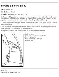
IMPORTANT NOTICE<br />
PLEASE READ<br />
Pinball games are now equipped with a SAFETY FEATURE to prevent shocks<br />
from the solenoid circuit when the coin door is opened. A new interlock switch<br />
assembly (part no. A-18249), located at the left of the coin door opening, has<br />
been added to the game. This assembly isa bracket containing the existing<br />
memory protect switch on the bottom and a new interlock switch on the top.<br />
When the coin door Is opened, this new Interlock switch opens, breaking the<br />
connection to the +50V and +20V winding of the transformer secondary.<br />
A special tool called the Service Switch Actuator Is provided for the<br />
servi·ceman/technician that repairs the game. This tool is painted yellow and<br />
located in a bag stapled inside the cabinet. The Service Switch Actuator slips<br />
over the Interlock switch and holds It closed while the coin door Is opened,<br />
allowing the serviceman to test and repair the solenoid circuit.<br />
Hold the top Interlock switch in, then slide the short end of the Service Switch<br />
Actuator over the top of the Interlock switch bracket and the long end over the<br />
center of the switch plunger to hold it In.<br />
SERVICE SWITCH ACTUATOR<br />
MEMORY PROTECT SWITCH-<br />
BRACKET----i<br />
I I<br />
I I
DEMOLITION MAN TM<br />
Wiiiiams Electronics Games, Inc. reserves the rights to make modifications and<br />
Improvements to Its products. The specifications and parts Identified In this<br />
manual are subject to change without notice.
RULES<br />
TRIGGERS ON GUN HANDLES OPERATE THE FLIPPERS.<br />
LOAD THE CLAW BY SHOOTING THE RIGHT RAMP WHEN THE DIVERTER IS OPEN.<br />
MOVE THE CLAW WITH THE FLIPPER BUTTONS OR THE GUN TRIGGER.<br />
SELECT THE CLAW GOAL BY DROPPING THE BALL WITH THE LAUNCH BUTTON OR THE<br />
GUN BUTTONS.<br />
"FREEZE" BALLS TO PREPARE FOR MUL TIBALL.<br />
START MUL TIBALL, WHEN ENABLED, BY SHOOTING LEFT LOOP.<br />
LATER MULTIBALL BAffiES ADD MORE JACKPOT SHOTS FOR BIGGER AWARDS.<br />
MAKE COMBINATION SHOTS TO BUILD COMBO BONUS, LIGHT EXTRA BALL AND ACTIVATE<br />
THE COMPUTER.<br />
COMPLETE MTL ROLLOVERS TO ADVANCE BONUS MULTIPLIER AND LIGHT EXTRA BALL.<br />
II
Table Of Contents<br />
Section 1 - Game Operation & Test Information<br />
Rules ................................................................................................................................................. ii<br />
(System WPC) ROM Summary .......................................................................................................... 1-1<br />
Pinball Game Assembly Instructions .................................................................................................. 1-2<br />
Pinball Assembly, Playfield Pitch Angle, & Leg Leveler Detail.. ............................................ 1-2<br />
Leg Bolt Locations .........................................................................................................·....·.. 1-2<br />
Line Cord Installation ............................................................................................................. 1-4<br />
Raising the Playfield ........................................................................................................................... 1-5<br />
Game Control Locations ..................................................................................................................... 1-6<br />
Game Operation ................................................................................................................................. 1-7<br />
Menu System Operation & Main Menu .............................................................................................. 1-8<br />
Bookkeeping Menu ............................................................................................................. 1-9<br />
B.1 Main Audits ........................................................................................................ 1-9<br />
B.2 Earnings Audits .................................................................................................. 1-9<br />
B.3 Standard Audits................................................................................................. 1-1 o<br />
B.4 Feature Audits................................................................................................... 1-11<br />
B .5 Hi stograt'l'.1$ .......................................................................................···· ······ ····· ·· 1-12<br />
B.6 Time-Stamps ...................................................................................................... 1-12<br />
Printouts Menu ...................................................................................................................... 1-13<br />
Test Menu ............................................................................................................................. 1-14<br />
T.1 Switch Edges ..................................................................................................... 1-14<br />
T.2 Switch Levels ..................................................................................................... 1-14<br />
T.3 Single Switches .................................................................................................. 1-14<br />
T.4 Solenoid Test. .................................................................................................... 1-15<br />
T.5 Flasher Test. ...................................................................................................... 1-15<br />
T.6 General Illumination Test ................................................................................... 1-15<br />
T.7 Sound & Music Test ........................................................................................... 1-16<br />
T.8 Single Lamp Test ............................................................................................... 1-16<br />
T.9 All Lamp Test. .................................................................................................:.. 1-16<br />
T.10 Lamp & Flasher Test ........................................................................................ 1-16<br />
T.11 Display Test. .................................................................................................... 1-16<br />
T.12 Flipper Coil Test ............................................................................................... 1-16<br />
T.13 Ordered Lamps Test ........................................................................................ 1-17<br />
T.14 Claw Test. ........................................................................................................ 1-17<br />
T.15 Empty Balls Test .............................................................................................. 1-18<br />
Utilities Menu ......................................................................................................................... 1-19<br />
U .1 Clear Audits....................................................................................................... 1-19<br />
U.2 Clear Coins ........................................................................................................ 1-19<br />
U.3 Reset H.S.T.D ................................................................................................... 1·19<br />
U.4 Set Time & Date ................................................................................................ 1-19<br />
U.5 Custom Message ............................................................................................... 1-19<br />
U.6 Set Game l.D .................................................................................................... 1-19<br />
U.7 Factory Adjustment ............................................................................................ 1-19<br />
U.8 Factory Reset. ................................................................................................... 1-19<br />
U.9 Preset ................................................................................................................ 1-20<br />
Difficulty Setting Table for U.S., Canadian, French, German & European<br />
Games ......................................................................................................... 1-20<br />
Preset Adjustments Table for U.S. & Canadian Games .............................. 1-20<br />
Preset Adjustments Table for German Games ........................................... 1-22<br />
U.1 O Clear Credits .................................................................................................... 1-22<br />
U .11 Auto Burn-in .........................................................................................·........... 1-22<br />
Adjustment Menu ........................................................................................................··........ 1 ·23<br />
A.1 Standard Adjustments ........................................................................................ 1 ·23<br />
A.2 Feature Adjustments .......................................................................................... 1-27<br />
A.3 Pricing Adjustments ........................................................................................... 1-31<br />
iii<br />
Copyright 1994<br />
Williams Electronics Games, Inc.
Section 1 - Game Operation & Test Information Continued .. .<br />
Pricing Table ................................................................................................ 1-33<br />
A.4 H.S.T.D. Adjustments .......................................................................................... 1.34<br />
A.5 Printer Adjustments ........................................................................................... " 1-35<br />
Error Messages ................................................................................................................................... 1-36<br />
Opto Theory ........................................................................................................................... 1 .37<br />
CPU Board LED Error Codes ............................................................................................... ·· 1-37<br />
Sound Board Beep Error Codes ............................................................................................. 1-37<br />
Cryoclaw/Elevator .................................................................................................................. 1-38<br />
LED List ............................................................................................................................................... 1-40<br />
Fuse List. ............................................................................................................................................. 1-41<br />
Maintenance Information ..................................................................................................................... 1-42<br />
Lubrication .............................................................................................................................. 1-42<br />
Switch Contacts ...................................................................................................................... 1-42<br />
Cleaning ................................................................................................................................. 1-42<br />
Playfield Disassembly ............................................................................................................. 1-43<br />
Removing the Cryoclaw ............................................................................................. 1-43<br />
Removing the Elevator ............................................................................................... 1-43<br />
Removing the Ramps ................................................................................................ 1-44<br />
Section 2 • Game Parts Information<br />
Backbox Assembly .............................................................................................................................. 2-2<br />
Cabinet Assembly ................................................................................................................................ 2-3<br />
Line Filter/Cordset Application Chart ................................................................................................... 2-4<br />
Sound Board Assembly ....................................................................................................................... 2-5<br />
Fliptronic II Board Assembly ............................................................................................................... 2-6<br />
Dot Matrix Controller Assembly ........................................................................................................... 2-7<br />
Power Driver Assembly ....................................................................................................................... 2-8<br />
CPU Board Assembly .......................................................................................................................... 2-10<br />
LED 7 Ball Trough Assembly, Opto 7 Ball Trough Assembly .............................................................. 2-11<br />
Coin Door Interface PC Board, Motor EMI PCB Assembly ................................................................. 2-12<br />
Flipper Opto PCB Assembly, DC Motor Control PCB Assembly ......................................................... 2-13<br />
7-switch Opto PCB Assembly, Cryoclaw Opto PCB Assembly .......................................................... 2-14<br />
Aux Driver (8-driver) PCB Assembly, Elevator Opto PCB Assembly .................................................. 2-15<br />
Flipper Assembly ................................................................................................................................. 2-16<br />
Kicker (slingshot) Arm Assembly ........................................................................................................ 2-18<br />
Outhole Ball Trough Assembly ............................................................................................................ 2-19<br />
Jet Bumper Assembly, Jet Bumper Coil Assembly ............................................................................. 2-20<br />
Ball Eject Assembly ............................................................................................................................. 2-21<br />
Kicker Bracket Assembly, Knocker Assembly ............................................................. ~ ......................... 2-22<br />
Tilt Mechanism Assembly ..................................................................................................................... 2-23<br />
Back Panel Assembly, Elevator Assembly .......................................................................................... 2-24<br />
Cryoclaw Assembly ............................................................................................................................. 2-26<br />
Control Handle Assemblies ................................................................................................................. 2-28<br />
Ball Popper Assembly ............................................................ : ............................................................. 2-30<br />
Ramp Diverter Assembly ..................................................................................................................... 2-31<br />
Chute Assembly ................................................................................................................................... 2-32<br />
Universal Power Interface Assembly ................................................................................................... 2-33<br />
Target Assemblies ............................................................................................................................... 2-34<br />
Posts .................................................................................................................................................... 2-35<br />
Unique Parts ........................................................................................................................................ 2-36<br />
Cables ................................................................................................................................................... 2-38<br />
Upper Playfield Parts Location ............................................................................................................ 2-39<br />
Lower Playfield Parts Location ............................................................................................................ 2-40<br />
iv
Section 2 • Game Parts lnfonnatlon Continued ...<br />
Rubber Rings ...................................................................................................................................... 2-41<br />
Lamp Matrix ........................................................................................................................................ 2-42<br />
Lamp Location .................................................................................................................................... 2-43<br />
Switch Matrix ...................................................................................................................................... 2-44.<br />
Switch Location .................................................................................................................................. 2-45<br />
Solenoid Table .................................................................................................................................... 2-46<br />
Solenoid Location ............................................................................................................................... 2-47<br />
Ramp Location .................................................................................................................................... 2-48<br />
Section 3 - Schematics, Wiring Diagrams & Circuit Theory<br />
Connector & Component ldentification ............................................................................................... 3-1<br />
Switch Matrix and Circuit .................................................................................................................... 3-2<br />
Dedicated Switch Circuit. .................................................................................................................... 3-3<br />
Lamp Matrix and Circuit. ............................................................................. :~:~ .................................... 3-4<br />
Solenoid Table .................................................................................................................................... 3-5<br />
Solenoid Wiring ................................................................................................................................... 3-6<br />
Flashlamp Wiring ................................................................................................................................ 3-7<br />
High Power and Low Power Solenoid Circuits ................................................................................... 3-8<br />
Flashlamp and Special (General Purpose) Solenoid Circuits ............................................................. 3-9<br />
General Illumination Circuits ............................................................................................................... 3-1 o<br />
Flipper Circuit Diagram ....................................................................................................................... 3-11<br />
Flipper Coil and E.0.S. Switch Circuit Diagrams ............................................................................... 3-12<br />
Flipper Cabinet Switch Circuit Diagrams ............................................................................................ 3-13<br />
Flipper Opto PCB Assembly ............................................................................................................... 3-14<br />
LED and Photo Transistor PCB Assemblies ....................................................................................... 3-15<br />
7 Ball Trough Photo Transistor PCB Assembly .................................................................................. 3-15<br />
7 Ball Trough LED PCB Assembly ..................................................................................................... 3-17<br />
7-0pto Switch PCB Assembly & Circuit Diagram ............................................................................... 3.18<br />
Cryoclaw Opto PCB Assembly & Circuit Diagram .............................................................................. 3-20<br />
D.C. Motor Control PCB Assembly ..................................................................................................... 3-21<br />
Elevator Opto PCB Assembly & Circuit Diagram ................................................................................ 3-22<br />
Motor EMI PCB Assembly .................................................................................................................. 3-23<br />
8-Driver PCB Assembly & Circuit Diagram ........................................................................................ 3-24<br />
Coin Door Interface PCB Assembly ................................................................................................... 3-26<br />
Sound Board lnterboard Wiring .......................................................................................................... 3-28<br />
CPU Board lnterboard Wiring ............................................................................................................. 3-29<br />
Dot Matrix Controller Board lnterboard Wiring ................................................................................... 3-30<br />
Fliptronic II Board lnterboard Wiring ................................................................................................... 3-31<br />
Power Driver Board lnterboard Wiring ................................................................................................ 3.32<br />
v
NOTES<br />
vi
SECTION 1<br />
Game Operation<br />
and<br />
Test Information<br />
IC<br />
aarm BOM :1 (OQmestic)<br />
Game ROM 1 (Eorejgo)<br />
Music!~Qb BQM<br />
MusiQf.S~Qb BQM<br />
Music!SJ;>eeQb BQM<br />
MusiQLS~eQh BQM<br />
Music1~cb BQM<br />
Music/~cb BQM<br />
Type<br />
2Zc:OO<br />
27c:OO<br />
2zc:00<br />
27c:OO<br />
27c:OO<br />
2Zc:OO<br />
27c00<br />
2zc00<br />
ROM<br />
SUMMARY<br />
Location Board Part Number<br />
w CRJ A-53~3-50026-l A<br />
w CRJ A-5343-50028-1 x<br />
SlJ2 AudQ A-53~3-5Q026-S2<br />
SLB &iaQ A-53~3-50026-SJ<br />
SU4 &ldiQ A-53~3-50026-S~<br />
SlE AudiQ A-53~3-5QQ26-S5<br />
Sl1) AugQ A-53!3-5Q02B-S6<br />
SU7 Aui;iQ A-53~3-5QQ26-SZ<br />
DEMOLITION MAN 1-1
PINBALL GAME ASSEMBLY INSTRUCTIONS<br />
DEMOLITION MAN<br />
IS A 5 BALL GAME.<br />
Power;<br />
Temo:<br />
Humidity:<br />
Domestic 120V @ 60Hz<br />
Foreign 230V@ 50Hz<br />
Japan 1 OOV @ 50HZ<br />
32°F to 100° F (O°C to 38°)C<br />
Not to exceed 95% relative.<br />
Dimensions: Width: 29" approx.<br />
Depth: 52" approx.<br />
Height: 76" approx.<br />
Weight; 334 lbs approx. (crated)<br />
1. Remove all cartons, parts, and other items from the shipping container and set them aside.<br />
2. Leg levelers and leg bolts are among the parts in the cash box. Install leg levelers on the front and<br />
rear legs (View 1 ). Place cabinet on a support and attach rear legs using leg bolts (View 2).<br />
3. Attach front legs using leg bolts (View 2).<br />
,- .... ..,<br />
I I<br />
I I ./\<br />
I I "'"' \<br />
I j/ .,.,.\<br />
"'"''<br />
< rt--,,,---"',,,<br />
- - -,<br />
-..;t_ \II,,"' _______ J I<br />
Detail View· Ltg Leveler<br />
;<br />
See Detail View I<br />
'<br />
VIEW 1<br />
0<br />
~\!<br />
-=--~A<br />
-=--<br />
n<br />
irl<br />
I ~l<br />
1111<br />
I 111<br />
'111<br />
I 111<br />
! "'<br />
G<br />
0<br />
'/~<br />
~· .. ~--=a I :V1<br />
s=- ~<br />
'/ !ii~ --=a<br />
s=- ~<br />
Jl I<br />
I I<br />
111'<br />
I 11<br />
111 I<br />
111, 1<br />
f.B.Qtil:<br />
'n'<br />
1111<br />
'n'<br />
I 11<br />
111 !<br />
1<br />
~ 1111<br />
VIEW 2<br />
I II<br />
·o· . . D<br />
.BEAB.<br />
~<br />
DEMOLITION MAN 1·2
4. Reach into the cabinet and backbox and ensure that the interconnecting cables are not kinked or<br />
pirched. Be careful to avoid damaging wires at any stage of the asserrbly process.<br />
5. Raise the hinged backbox upright and latch It into position. Unlock the backbox, and remove the<br />
backglass. Remove the shipping screws holding the Insert Panel. Unlatch and open the Insert<br />
Panel. Carefully lift up the Speaker Panel and lay It down on the playfield glass. (Be careful not to<br />
damage the Dot Matrix Display/Driver.) This allows access to the bolt holes used for securing the<br />
backbox upright. To secure the backbox, install the washer-head mounting bolts through the<br />
bottom holes of the backbox into the threaded fasteners in the cabinet. Close and latch the Insert<br />
Panel. Replace the Speaker Panel. Reinstall the backglass, and lock the backbox.<br />
&CAUTION<br />
FAILURE TO INSTALL the backbox mounting hardware properly can cause personal injury.<br />
NEVER TRANSPORT a pinball game with the hinged backbox erect. Always lower the backbox<br />
forward onto the playfield cabinet on a layer of protective material to prevent marring or damage and<br />
possible personal inj.lry.<br />
6. Extend each leg leveler slightly below the leg bottom, so that all four foot pads are extended about<br />
the same distance. Remove the cabinet from its support and place It on the floor.<br />
7. Unlock and open the coin door. Move the molding latch lever toward the left side of the game. Lift<br />
the front molding off the playfield cover glass return the latch lever toward the right, and close the<br />
coin door. Carefully slide the glass downward, until it clears the grooves of the left and right side<br />
moldings. Lift the glass up and cmay from the game, storing it carefully to avoid breakage.<br />
8. Place a level or an inclinometer on the playfield surface. Adjust the leg levelers for proper playfield<br />
level (side-to-side). NOTE: This measurement must be made ON the playfield, not the cabinet nor<br />
the playfield cover glass. lighten the nut on each leg leveler shaft to maintain this setting.<br />
9. Adjust the leg levelers to the proper playfield pitch (back-to-front). The recommended pitch level is<br />
6-1/2 degrees.<br />
! IMPORTANT !<br />
Playfield pitch angle can affect the operation of the plumb bob tilt. The plumb bob weight is among<br />
the parts in the cash box; the operator should install the weight and adjust this tilt mechanism for<br />
proper operation, after completion of the desired playfield pitch angle setting. The unit is factory<br />
installed for a 6-112 degree angle. If an adjustment is necessary, loosen the screw at the bottom of<br />
the unit. Move the pointer, one grove at a time to the left or the right, depending on the degree<br />
desired. Hold the pointer in place and tighten screw.<br />
1 O. Move the game into the desired location; recheck the level and pitch angle of the playfield.<br />
11 . Be sure the required number of balls are installed. This game uses five balls.<br />
12. Install full playfield mylar, if desired. NOTE: The playfield is coated with a special hardcoat surface<br />
and does not require a protective mylar. However, mylars can be purchased through your local<br />
Williams Distributor. Specify part number 03-9118-1 for full playfield mylar.<br />
DEMOLITION MAN 1·3
13. Remove the foam from the Cryoclaw and pull the two pieces of cardboard from the Car Tunnel.<br />
14. Clean and reinstall the playfield cover glass. Prepare the game for player operation.<br />
15. To attach the line cord, remove the envelope stapled to the inside of the cabinet (near the<br />
cashbox). Remove the four Phillips-head screws that mount to line cord cover plate to the rear<br />
cabinet. Match the prongs on the plug with the holes in the receptacle, and push the line cord<br />
securely into place. Make sure the cord is aligned with the indentation on the cover plate<br />
(indentation should point toward bottom of the cabinet). Remount line cord cover plate. If desired,<br />
four tamper resistant screws have been provided in an enevlope marked "Security Screws" (located<br />
in the cashbox) to remount cover plate.<br />
DEMOLITION MAN 1·4
.Li.CAUTION<br />
RAISING THE PLA YFIED<br />
Do not raise the playfleld straight up! This game uses a slide assembly to raise and<br />
lower the playfield.<br />
To raise the playfleld.<br />
1 . Grasp bottom arch and carefully lift up playfield<br />
only high enough to clear sat ety brackets. Rear<br />
guide legs should not hit wood guide rails or be used<br />
to slide out playfield.<br />
Rear Gulde Leg<br />
(2 used)<br />
Wood Gulde Rail<br />
(2used)<br />
2. Pull the playfield out toward you until it stops<br />
(rest position) and raise it approximately 3".<br />
Be sure playfleld Is In locked position and<br />
does not slide back Into the cabinet. If It<br />
does, repeat Step 2 before proceed Ing to<br />
Step 3.<br />
3 • Rotate playfield to upright service position (lean<br />
on backbox) by pulling toward you and up. Listen for<br />
the sound of a click; this insures locking and pivoting<br />
sequence.<br />
To lower the playfleld.<br />
4 • Rotate the playfield to the rest position. This<br />
unlocks the pivoting mechanism.<br />
5. Push back playfield into cabinet and into<br />
playing position.<br />
-<br />
Slide Mechanism -l-1"t<br />
(2used)<br />
Pivot Mechanism<br />
(2used)<br />
DEMOLITION MAN 1·5
GAME CONTROL LOCATIONS<br />
Cabinet Switches<br />
The On-Off Swjtch is on the bottom of the cabinet near the right front leg.<br />
The Start Button is a pushbutton to the left of the coin door on the cabinet exterior. Press the Start<br />
button to begin a game, or during the diagnostic mode, to ask for HELP.<br />
Coin Door Buttons<br />
The operator controls all game adjustments, obtains bookkeeping information, and diagnoses problems,<br />
using only four pushbutton switches mounted on the inside of the coin door. The Coin Door Buttons<br />
have two modes of operation Normal Function and Test Function.<br />
Normal Function<br />
The Service Credjts button puts credits on the game that are not included in any of the game audits.<br />
The Volume Up (+)button raises the sound level of the game. Press and hold the button until the<br />
desired level is reached.<br />
The Volume Down(-) button lowers the sound level of the game. Press and hold the button until the<br />
desired level is reached. See Adjustment A.1 28 to shut sound Off completely.<br />
The Begin Test button starts the Menu System Operation and changes the Coin Door Buttons from<br />
Normal Function to Test Function.<br />
Test Function<br />
The Escape button allows you to get out of a menu selection or return to the Attract Mode.<br />
The UQ.1+) button allows you to cycle forward through the menu selections or adjustment choices.<br />
The Down (-) button allows you to cycle backward through the menu selections or adjustment<br />
choices.<br />
The fo1er_button allows you to get into a menu selection or lock in an adjustment choice.<br />
Holding the Enter button for five seconds, during the Attract Mode, resets the High<br />
Scores.<br />
.,,,,.....--- ............<br />
,,,,,.~ '',,<br />
Start Button<br />
/ ', Interlock Sw.<br />
I I<br />
' \<br />
,' NORMAL MODE FUNCTION \<br />
- Flipper Button<br />
I SERVICE VOLUME BEGIN I<br />
: CREDITS 11111" 1 TEST \ Launch Ball Button<br />
: 0000 :<br />
I<br />
I<br />
1 ESCAPE • + ENTER 1...,<br />
\ TEST MODE FUNCTION / ...............<br />
\ I<br />
\ I<br />
'<br />
I<br />
' ;<br />
' ;<br />
' ,,<br />
.... , ........ ______ .,,,.,,,.,<br />
Coln Door Button Locations /<br />
Memory Protect Sw.<br />
Tilt Mechanism<br />
.... .. ... Extra Ball Button<br />
... ,<br />
.........................<br />
' On-Off Switch<br />
DEMOLITION MAN 1·6
GAME OPERATION<br />
&cAUTION<br />
After assembly and Installation at Its site location, this game must be plugged Into a<br />
properly grounded outlet to prevent shock hazard, and to assure proper game<br />
operation. DO NOT use a 'cheater' plug to defeat the ground pin on the llne cord. DO<br />
NOT cut off the ground pin.<br />
POWERING UP With the coin door closed, plug the game in, and switch it On. In normal operation,<br />
Testing shows in the displays as the game performs Start-up Tests. Once the Start-up Tests have been<br />
successfully completed the last score is displayed. After which, the game goes into the Attract Mode.<br />
Note: After the game has been on location for a time, the Start-up Tests may contain messages<br />
concerning game problems. The section entitled 'Error Messages' contains more details concerning<br />
messages displayed at each game turn-on.<br />
Open the coin door and press the Begin Test switch. The display shows the game name, number, and<br />
software revision. The message changes. The display shows the sound software revision, the revision<br />
level of the system software, and the date the software was revised.<br />
Example: Game Name Sound Rev. L·1<br />
500XX Rev. L·X SY. O.XO X·X·94<br />
Press the Enter button to enter the WPC Menu System (refer to the section entitled "Menu System<br />
Operation" for more information). Slide the Service Switch Actuator over the top interlock switch located<br />
in the bottom left corner of the coin door opening. Perform the entire Test Menu routine to verify that<br />
the game is operating satisfactorily.<br />
ATTRACT MODE*. After completing the Test Menu routine, press the Escape button three times<br />
to enter the Attract Mode. During the Attract Mode, the score display shows a series of messages<br />
informing the player concerning, recent highest scores*, "custom messages"", and the score to achieve<br />
to obtain a Replay award*.<br />
CREDIT POSTING. Insert coin(s). A sound is heard for each coin, and the display shows the<br />
number of credits purchased. So long as the number of maximum allowable credits* are NOT exceeded<br />
by coin purchase or high score, credits are posted correctly.<br />
STARTING A GAME. Press the Start button. A startup sound plays, and the credit amount<br />
shown in the display decreases by one. The display flashes 00 (until the first playfield switch is<br />
actuated), and shows ball 1. If credits are posted, additional players may enter the game by pressing the<br />
Start button once for each player, before the end of play on the first ball. Press the handle buttons or<br />
the Launch Ball button to launch a ball. Press the handle triggers or the flipper buttons to operate the<br />
flippers.<br />
TILTS. Actuating the cabinet tilt switch inside the cabinet ends the current game and then proceeds to<br />
the Game Over Mode. With the third closure* of the plumb bob tilt switch, the player loses the remaining<br />
play of that ball, but can complete the game.<br />
END OF A GAME. All earned scores and bonuses are awarded. If a player's final score exceeds<br />
the specified value, the player receives a designated award for achieving the current highest score. A<br />
random digit set* appears in the display. Credit* may be awarded, when the last two digits of any player's<br />
score match the random digits. Match, high score, and game over sounds are made, as appropriate.<br />
GAME OVER MODE. The Game Over display shows in the display. Then, the high scores<br />
flash. The game proceeds to the Attract Mode.<br />
* - Operator-adjustable feature<br />
DEMOLITION MAN 1·7
MENU SYSTEM OPERATION<br />
The Main Menu allows you to ·choose from several categories, which in turn lead to other menus to choose<br />
from. To access the Main Menu, open the coin door and press the Begin Test button, then press the<br />
Enter button. Press the Up or Down buttons to cycle through the Main Menu. Press the Enter button to<br />
access a menu. Press the Escape button to return to the Main Menu. Press the Start button for HELP at<br />
anytime.<br />
MAIN MENU<br />
B. Bookkeeping Menu<br />
P. Printouts Menu<br />
T. Test Menu<br />
U. Utllltles Menu<br />
A. Adjustments Menu<br />
_6_.1 Main Audits<br />
B.2 Earnina Aucits<br />
B.3 Standard Audits<br />
B.4 Feature Audits<br />
B.5 Histoarams<br />
~e-stamos<br />
P .1 Earnings Data<br />
P .2 Main Audits<br />
P .3 Standard Audit1<br />
P.4 Feature Audits<br />
P .5 Score HistQgrams<br />
P.6 Time Histograms<br />
P,Z Ilmi·Slim.QS<br />
P.8 All Data<br />
T.1 Switch E~es Test<br />
I 2 Switch I lil!r!SIS Iest<br />
T .3 Single Switches Test<br />
T.4 Solenoid Test<br />
I 5 Elasbec Iast<br />
T.6 General Illumination Test<br />
T. 7 Sound and Music Test<br />
T.S Single Li!I!5U! Iist<br />
T.9 All Li!I!R!i Ii!it<br />
T.10 Lam.Q & Flasher Test<br />
T.11 Oi~Rl!l~ IiSt<br />
T .12 Flieeer Coil Test<br />
T.13 Ordered Lames Test<br />
T.14 ClawTest<br />
T.15 Empty Balls Test<br />
U.1 Clear Audits<br />
U.2 r.IAAr r.nln!i!<br />
U.3 Reset H.S.T.D.<br />
U.4 Set Time &-Date<br />
U.5 Custom Messaae<br />
U.6 Set Game 1.0.<br />
U.7 Factorv Adiustments<br />
U.8 Factorv Resets<br />
JJ...9 Pres9ts<br />
U.1 O Clear Credits<br />
U.11 Auto Burn-in<br />
A.1 Standard Adiustments<br />
A.2 Feature Adiustments<br />
A.3 Pricina Adiustments<br />
A.4 H.S.T.D. Mustments<br />
A.5 Printer Adiustments<br />
press Escape<br />
To move out of a menu selection.<br />
Press Enter<br />
To get into a menu selection.<br />
Press Up<br />
Increases sequence; (ex. A.1<br />
A.2, A.3, A.4).<br />
Press Down<br />
Decreases sequence; (ex. A.4,<br />
A.3, A.2, A.1 ).<br />
Use Up or Down to cycle through<br />
the selections in a menu.<br />
Use Escape and Enter to move<br />
into and out of the selected menu.<br />
DEMOLITION MAN 1·8
Press the Up or Down buttons to cycle through the menu. Press the Enter button to access an audit<br />
menu. Press the Escape button to return to the Bookkeeping Menu.<br />
B. BOOKKEEPING MENU<br />
B. 1 Main Audits<br />
B. 2 Earning Audits<br />
B. 3 Standard Audits<br />
B. 4 Feature Audits<br />
B.5 Histograms<br />
B.6 Time-Stamps<br />
One Button Audit System. The Bookkeeping Menu is obtainable directly from the Attract<br />
Mode. Repeatedly pressing the Enter button, while in the Attract Mode, will cycle through all of the game<br />
audits.<br />
B.1 Main Audits<br />
B.1 01 Total Earnings 00<br />
B.1 02 Recent Earnings 00<br />
B.1 03 Free Play Percent 00<br />
B.1 04 Average Ball lime 00<br />
8.1 05 lime Per Credit 00<br />
8.1 06 Total Plays 00<br />
B.1 07 Replay Awards 00<br />
B.1 08 Percent Replays 00<br />
B.1 09 Extra Balls 00<br />
B.1 10 Percent Extra Ball 00<br />
8.2 Earning Audits<br />
B.2 01 Recent Earnings 00<br />
B.2 02 Recent Left Slot 00<br />
B.2 03 Recent Center Slot 00<br />
B.2 04 Recent Right Slot 00<br />
B.2 05 Recent 4th Slot 00<br />
B.2 06 Recent Paid Credits 00<br />
B.2 07 Recent Service Credits 00<br />
8.2 08 Total Earnings* 00<br />
8.2 09 Total Left Slot* 00<br />
B.2 10 Total Center Slot* 00<br />
8.2 11 Total Right Slot* 00<br />
B.2 12 Total 4th Slot* 00<br />
8.2 13 Total Paid Credits* 00<br />
8.2 14 Total Service Credits* 00<br />
*These audits are NOT resettable. They are a record of the earnings of the game since the ''CLOCK 1ST<br />
SET' Time-stamp.<br />
DEMOLITION MAN 1·9
B.3 Standard Audits<br />
B.3<br />
B.3<br />
01<br />
02<br />
B.3 03<br />
B.3 04<br />
B.3 05<br />
B.3 06<br />
B.3 07<br />
B.3 08<br />
B.3 09<br />
B.3 10<br />
B.3 11<br />
B.3 12<br />
B.3 13<br />
B.3 14<br />
B.3 15<br />
B.3 16<br />
B.3 17<br />
B.3 18<br />
B.3 19<br />
B.3 20<br />
B.3 21<br />
B.3 22<br />
B.3 23<br />
B.3 24<br />
B.3 25<br />
B.3 26<br />
B.3 27<br />
B.3 28<br />
B.3 29<br />
B.3 30<br />
B.3 31<br />
B.3 32<br />
B.3 33<br />
B.3 34<br />
B.3 35<br />
B.3 36<br />
B.3 37<br />
Games Started<br />
Total Plays•<br />
Total Free Play<br />
Free Play Percent<br />
Replay Awards<br />
Percent Replays<br />
Special Awards<br />
Percent Special<br />
Match Awards<br />
Percent Match<br />
H.S.T.D. Credits<br />
Percent H.S.T.D<br />
Extra Ball<br />
Percent Extra Ball<br />
Tickets Awarded<br />
Percent Tickets<br />
Left Drains<br />
Right Drains<br />
Average Ball Time<br />
Average Game Time<br />
Play Time<br />
Minutes On<br />
Balls Played<br />
Tilts<br />
Replay 1 Awards<br />
Replay 2 Awards<br />
Replay 3 Awards<br />
Replay 4 Awards<br />
1 Player Games<br />
2 Player Games<br />
3 Player Games<br />
4 Player Games<br />
H.S.T.D. Reset Count<br />
Burn-in Timet<br />
1st Replay Level<br />
Left Flipper<br />
Right Flipper<br />
00<br />
00<br />
00<br />
00<br />
00<br />
00<br />
00<br />
00<br />
00<br />
00<br />
00<br />
00<br />
00<br />
00<br />
00<br />
00<br />
00<br />
00<br />
00<br />
00<br />
00:00:00<br />
00<br />
00<br />
00<br />
00<br />
00<br />
00<br />
00<br />
00<br />
00<br />
00<br />
00<br />
00<br />
00:00:00<br />
00<br />
00<br />
00<br />
* "Total Plays" only counts on completed games. A game is considered complete when the final ball<br />
begins. Audit information from incomplete games is ignored. Operation for test and service do not affect<br />
audits.<br />
t This audit is not resettable.<br />
DEMOLITION MAN 1·10
B .4<br />
Feature Audits<br />
B.4 01<br />
B.4 02<br />
B.4 03<br />
B.4 04<br />
B.4 05<br />
B.4 06<br />
B.4 07<br />
B.4 08<br />
B.4 09<br />
B.4 10<br />
B.4 11<br />
B.4 12<br />
B.4 13<br />
B.4 14<br />
B.4 15<br />
B.4 16<br />
B.4 17<br />
B.4 18<br />
B.4 19<br />
B.4 20<br />
B.4 21<br />
B.4 22<br />
B.4 23<br />
B.4 24<br />
B.4 25<br />
B.4 26<br />
B.4 27<br />
B.4 28<br />
B.4 29<br />
B.4 30<br />
B.4 31<br />
B.4 32<br />
B.4 33<br />
B.4 34<br />
B.4 35<br />
B.4 36<br />
8.4 37<br />
B.4 38<br />
B.4 39<br />
B.4 40<br />
B.4 41<br />
Buy-in Extra Balls<br />
Time per Credit<br />
Combo 1st Extra Ball<br />
Combo 2nd Extra Ball<br />
Bonus X Extra Ball<br />
Computer Extra Ball<br />
Total Multiballs<br />
1st Multiballs<br />
2nd Multiballs<br />
3rd Multiballs<br />
4th Multiballs<br />
Computer Awards<br />
Ball Saves<br />
Jackpots<br />
Super Jackpots<br />
Combos<br />
Big Combos<br />
Claw Visits<br />
Claw Opened<br />
Capture Simon<br />
Super Jets<br />
Prison Break<br />
Claw Freezes<br />
AcMags<br />
Double Prison Break<br />
Triple Prison Break<br />
5-ball Multiballs<br />
Quick Freezes<br />
Left Ramps<br />
Right Ramps<br />
Center Ramps<br />
Side Ramps<br />
Bonus X<br />
Car Crashes<br />
Eyeball Hits<br />
Explode Hurry-up<br />
Standup Complete<br />
Demolition lime<br />
D. lime Champ Credits<br />
Secret Features<br />
Left Handle<br />
B.4 42 Right Handle<br />
Number of times player bought an extra ball 00% 00<br />
Average number of minutes player/credit paid 00% 00<br />
Number of times 1st extra ball lit from Combo 00% 00<br />
Number of times 2nd extra ball lit from Combo 00% 00<br />
Number of times extra ball lit from Bonus X 00% 00<br />
Number of times extra ball lit from Computer 00% 00<br />
Total number of multiballs played 00% 00<br />
Number of 1st multiballs played 00% O Number of 2nd multiballs played 00% 00<br />
Number of 3rd multiballs played 00% 00<br />
Number of 4th multiballs played 00% 00<br />
Number of computer awards 00% 00<br />
Number of times the ball was saved 00% 00<br />
Number of jackpots collected 00% 00<br />
Number of super jackpots collected 00% 00<br />
Number of Combos made 00% 00<br />
Number of 4-way and higher Combos made 00% 00<br />
Number of times the Cryoclaw was visited 00% 00<br />
Number of times the Cryoclaw was opened 00% 00<br />
Number of times Capture Simon selected 00% 00<br />
Number of times Super Jets selected 00% 00<br />
Number of times Prison Break selected 00% 00<br />
Number of times Freeze selected 00% 00<br />
Number of times AcMag selected 00% 00<br />
Number of times Prison Break doubled 00% 00<br />
Number of times Prison Break tripled 00% 00<br />
Number of times 5-ball Multi ball was played 00% 00<br />
Number of times Quick Freeze was made 00% 00<br />
Number of times the left ramp was made 00% 00<br />
Number of times the right ramp was made 00% 00<br />
Number of times the center ramp was made 00% 00<br />
Number of times the side ramp was made 00% 00<br />
Number of times the Bonus X was boosted 00% 00<br />
Number of times the car crash award collected 00% 00<br />
Number of times the eyeball target was hit 00% 00<br />
Number of times Explode Hurry-up mode started 00% 00<br />
Number of times standup targets completed 00% 00<br />
Number of times Demolition Time started 00% 00<br />
Number of credits award for Demo Time Champ 00% 00<br />
Number of secret features activated 00% 00<br />
Number of times the left handle trigger was used<br />
to flip flippers 00% 00<br />
Note that the standard audit B.3 36 Left Flipper includes flips<br />
made by BOTH flipper button and handle trigger.<br />
Number of times the right handle trigger was used<br />
to flip flippers 00% 00<br />
Note that the standard audit B.3 37 Right Flipper includes flips<br />
made by BOTH the flipper button and the handle trigger.<br />
DEMOLITION MAN 1·11
B.5 Histograms<br />
8.5 01 0-1.9 Million Scores 00% 00<br />
8.5 02 2-4.9 Million Scores 00% 00<br />
8.5 03 5-9.9 Million Scores 00% 00<br />
8.5 04 10-19 Million Scores 00% 00<br />
8.5 05 20-29 Million Scores 00% 00<br />
8.5 06 30-39 Million Scores 00% 00<br />
8.5 07 40-49 Million Scores 00% 00<br />
8.5 08 50-69 Million Scores 00% 00<br />
8.5 09 70-99 Million Scores 00% 00<br />
B.5 10 100-149 Million Scores 00% 00<br />
8.5 11 150-199 MillionScores 00% 00<br />
B.5 12 200-299 Million Scores 00% 00<br />
B.5 13 Over 300 Million Scores 00% 00<br />
B.5 14 Game Time 0.0-1.0 Mins 00% 00<br />
B.5 15 Game Time 1.0-1.5 Mins 00% 00<br />
B.5 16 Game Time 1.5-2.0 Mins 00% 00<br />
8.5 17 Game Time 2.0-2.5 Mins 00% 00<br />
B.5 18 Game Time 2.5-3.0 Mins 00% 00<br />
B.5 19 Game Time 3.0-3.5 Mins 00% 00<br />
B.5 20 Game Time 3.5-4.0 Mins 00% 00<br />
8.5 21 Game Time 4-5 Mins 00% 00<br />
8.5 22 Game Time 5-6 Mins 00% 00<br />
8.5 23 Game Time 6-8 Mins 00% 00<br />
8.5 24 Game Time 8-1 O Mins 00% 00<br />
8.5 25 Game Time 10-15 Mins 00% 00<br />
8.5 26 Game Time Over 15 Mins 00% 00<br />
B.6 Time-Stamps<br />
Time-Stamps Menu allows you to view dates and times that are important to game software.<br />
8.6 01 Current Time<br />
B.6 02 Clock 1st Set<br />
B.6 03 Clock Last Set<br />
B.6 04 Audits Cleared<br />
B.6 05 Coins Cleared<br />
B.6 06 Factory Setting<br />
8.6 07 Last Game Start<br />
8.6 08 Last Replay<br />
B.6 09 Last H.S.T.D. Reset<br />
B.6 10 Champion Reset<br />
B.6 11 Last Printout<br />
8.6 12 Last Service Credit<br />
DEMOLITION MAN 1·12
Press the Up or Down buttons to cycle through the menu. Press the Enter button to access a menu.<br />
Press the Escape button to return to the Printouts Menu.<br />
P. PRINTOUTS MENU<br />
(optional board required)<br />
P. 1 Earnings Data<br />
P. 2<br />
P . 3<br />
Main Audits<br />
Standard Audits<br />
P. 4 Feature Audits<br />
P.5 Score Histograms<br />
P. 6<br />
P. 7<br />
Time Histograms<br />
Time-Stamps<br />
P .8 All Data<br />
The Printouts Menu is a combination of the other menus. This menu allows you to access and print<br />
information in the available menu selections.<br />
If no printer is attached the the message "Waiting for Printer" appears in the displays.<br />
NOTE: Set the print specification from the Adjustment Menu, A.5 Printer Adjustments.<br />
DEMOLITION MAN 1·13
Use the Service Switch Actuator to hold In the top Interlock switch located In the<br />
bottom left corner of the coin door opening. The actuator must be In place In order to<br />
activate the solenoids and flash/amps.<br />
Press the Up or Down buttons to cycle through the menu. Press the Enter button to access a test. Press<br />
the Escape button to return to the Test Menu. NOTE: During any test, press the Start button to obtain<br />
the wire color, driver number, connector number and fuse location.<br />
T. TEST MENU<br />
T. 1 Switch Edges Test<br />
T. 2 Switch Levels Test<br />
T .3 Slngle Switch Test<br />
T. 4 Solenoid Test<br />
T. 5 Flasher Test<br />
T .6 General lllumlnatlon Test<br />
T. 7 Sound & Music Test<br />
T .8 Slngle Lamps Test<br />
T. 9 All Lamps Test<br />
T. 1 o Lamp & Flasher Test<br />
T. 11 Display Test<br />
T. 12 Flipper Coll Test<br />
T. 13 Ordered Lamps Test<br />
The switch matrix, on the left side of the display, shows the state of all switches. A dot indicates<br />
the switch is open, a square indicates the switch is closed. The numbers assigned to each switch indicate<br />
where the switch is located in the matrix. The number on the left indicates the column, the number on the<br />
right indicates the row. Example - Switch 23 is 2nd column, 3rd row.<br />
A short to ground - on either the row or column wire - appears as a shorted row(s). However, a<br />
column wire shorted to ground disappears when all of the indicated row switches are open. A row wire<br />
shorted to ground does not disappear.<br />
A shorted diode in the switch matrix can cause other switches to appear closed. These<br />
"phantom" switches (though not actually closed), complete a rectangle in the switch matrix. Therefore, if<br />
two switches in the same column are closed (example; #22 and #24), and a third switch is pressed in<br />
another column but in the same row as one of the first two (example; #32), the "phantom" switch #34 is<br />
falsely indicated as closed. The switch with the shorted diode is diagonally opposite the "phantom" switch<br />
(in this case #22).<br />
T. 1 Switch Edges Test Press each switch one at a time. The name and number of the<br />
switch is shown in the display. If a switch other then the one pressed, or no switch at all is<br />
indicated, the system has detected a problem with the switch circuit.<br />
T. 2 Switch Levels Test This test automatically cycles through all switches that are<br />
detected closed. The name and number of each switch that is detected is shown in the display. A<br />
filled square indicates the switch's position in the matrix.<br />
T.3 Single Switches Test The Single Switch Test isolates a particular switch by blocking<br />
signals from all other switches. Use the Up or Down buttons to select the switch to be tested.<br />
DEMOLITION MAN 1·14
T. 4 Solenoid Test The Solenoid Test has three modes - Repeat, Stop, and Run. Only one<br />
solenoid should pulse at a time. The system has detected a problem if more then one solenoid<br />
pulses, a solenoid comes on and stays on, or no solenoids pulse during the Repeat or Run<br />
modes.<br />
Repeat The Repeat mode pulses a single solenoid. After entering this test,<br />
Solenoid 1 shows in the display and the corresponding solenoid activates. Press the Up<br />
or Down button to cycle through the solenoids, one at a time. The same solenoid pulses<br />
until the Up or Down button is pressed. Either press the Escape button to return to the<br />
Test Menu, or press the Enter button to move to the next mode.<br />
Stop The Stop mode halts the Solenoid Test. Press Enter during the Repeat<br />
mode and the Solenoid Test stops. No solenoids should be activated while the test is<br />
stopped. Either press the Escape button to return to the Test Menu, or the Enter button<br />
to move to the next mode.<br />
Run The Run mode cycles through the solenoids automatically. The display<br />
shows the name and number of the solenoid currently being pulsed.<br />
T .5 Flasher Test This tests the flashlamp part of the solenoid circuit exclusively. This, like<br />
the Solenoid Test, has three modes - Repeat, Stop, and Run. During this test only one flashlamp<br />
circuit should pulse at a time. The system has detected a problem if more then one circuit pulses,<br />
a circuit stays on, or no circuits pulse during the Repeat or Run modes.<br />
Repeat The Repeat mode pulses a single flashlamp. After entering this test the<br />
name and number of the first flashlamp circuit shows in the display and the corresponding<br />
bulb(s) flash. Press the Up or Down buttons to cycle through all of the flashlamps circuits<br />
one at a time. The same circuit pulses until press the Up or Down button is pressed.<br />
Either press the Escape button to return to the Test Menu, or press the Enter button to<br />
advance to the next mode.<br />
Stop The Stop mode halts the Flasher Test. No flashlamp circuit should be<br />
active during this mode. Either press the Escape button to return to the Test Menu, or<br />
press the Enter button to advance to the next mode.<br />
Run The Run mode cycles through the flashlamps automatically. The display<br />
shows the name and number of the flashlamp circuit currently being pulsed as the<br />
corresponding bulb(s) flashes.<br />
T .6 General Illumination Test This test checks all of the General Illumination circuits.<br />
There are two modes of operation - Stop and Run.<br />
Stop Press the Up or Down buttons to cycle through the General Illumination<br />
Test manually. All illumination is tested first, followed by an individual circuit test. The<br />
circuit name and number shows in the display while the corresponding lamps lights. If any<br />
other results occur the system has detected an error.<br />
Run Press the Enter button any time during Stop mode and the General<br />
Illumination Test cycles through automatically. For each circuit shown in the display the<br />
corresponding bulbs should light. If any other results occurs the system has detected a<br />
problem.<br />
DEMOLITION MAN 1·15
T.7 Sound and Music Test The Sound and Music Test checks the audio circuits.<br />
This test has three modes for testing the sound and roosic circuits - Run, Repeat, and Stop.<br />
Run The Run mode steps through a sequence of sounds and music. Press<br />
the Up or Down buttons during this portion of the Sound and Music test to advance to a<br />
particular sound or tune without having to wait for the program to play all the sounds<br />
available in the test. A sound or tune should be heard for each name and number that<br />
appears in the display. Any other results indicates the system has detected a problem.<br />
Repeat Press the Enter button at any time during the Run mode to cause the<br />
program to stop and repeat a particular sound/tune. The same sound should repeat<br />
continuously until the Up or Down button is pressed. Any other results indicates the<br />
system has detected a problem.<br />
Stop Press the Enter button at any time during the Repeat mode to stop this<br />
test altogether. Nothing should be heard. Any other results indicates the system has<br />
detected a problem.<br />
T.8 Single Lamp Test The number assigned to each lamp indicates the lamp's position<br />
in the matrix. The number on the left indicates the column. The number on the right indicates the<br />
row. Example - Lamp 23 means 2nd column, 3rd row.<br />
This test checks each lamp circuit individually. Press the Up or Down button to cycle through this<br />
test. For each name and number that is shown in the display the corresponding lamp should light.<br />
Any other results indicates the system has detected a problem.<br />
T. 9 All Lamps Test This test causes all the controlled lamps to flash at the same time.<br />
Every controlled lamp should flash. Any other results indicates the system has detected a<br />
problem.<br />
T. 1 0 Lamp and Flasher Test This test causes all the flashlamps and the controlled<br />
lamps to flash at the same time. The controlled lamps blink, while the flashlamps cycle from<br />
highest to lowest. Any other results indicates the system has detected a problem.<br />
T .11 Display Test<br />
This test automatically checks every dot in the Dot Matrix Display.<br />
A series of patterns appear in sequence. Each pattern turns on and off a section of dots. Every<br />
dot on the matrix display should be turned on and off during this test.<br />
T .12 Flipper Coil Test<br />
The Flipper Coil Test has three modes - Repeat, Stop, and Run.<br />
Only one Flipper should pulse at a time. The system has detected a problem if more then one<br />
flipper pulses, a flipper comes on and stays on, or no flippers pulse during the Repeat or Run<br />
modes.<br />
Repeat The Repeat mode pulses a single flipper. After entering this test, flipper<br />
coil 01 shows in the display and the corresponding coil activates. Press the Up or Down<br />
button to cycle through the flipper coils, one at a time. The same solenoid pulses until the<br />
Up or Down button is pressed. Either press the Escape button to return to the Test<br />
Menu, or press the Enter button to move to the next mode.<br />
DEMOLITION MAN 1·16
T.12 Flipper Coll Test Continued .••<br />
Stop The Stop mode halts the Flipper Coil Test. Press Enter during the<br />
Repeat mode and the test stops. No coils should be activated while the test is stopped.<br />
Either press the Escape button to return to the Test Menu, or the Enter button to move to<br />
the next mode.<br />
Run The Run mode cycles through the flippers automatically. The display<br />
shows the name and number of the flipper coil currently being pulsed.<br />
T. 1 3 Ordered Lamps Test The number assigned to each lamp indicates the lamp's<br />
position in the matrix. The number on the left indicates the column. The number on the right<br />
indicates the row. Example - Lamp 23 means 2nd column, 3rd row.<br />
This test checks each lamp circuit individually. Press the Up or Down button to cycle through the<br />
lamps. Lamps light in a clock-wise or counter clock-wise direction starting from the bottom of the<br />
playfield. Direction depends on which button, Up or Down, is pressed. For each name and<br />
number that is shown in the display the corresponding lamp should light. Any other results<br />
indicates the system has detected a problem.<br />
T .14 Claw Test The Claw test aids in troubleshooting the Cryoclaw/Elevator mechanism.<br />
The claw test provides several functions for activating the mechanism, while simultaneously<br />
displaying the states of the opto switches associated with the mechanism. For more information<br />
on claw operation, see Theory of Operation.<br />
Switch display •<br />
The states of the following switches are constantly monitored and displayed during the Claw test:<br />
Elevator Index, Elevator Hold, Claw Left, Claw Right. The box next to each switch name contains<br />
an X when the switch is activated (blocked).<br />
Claw Test Functions<br />
Use the diagnostic Up and Down buttons to step through the available Claw test functions. The functions<br />
operate only when the diagnostic Enter button is pressed. When a function is active its name is inverted<br />
on the display screen. To stop claw function at any time simply release the Enter button.<br />
Auto Run<br />
During the Auto Run function the elevator is continuously monitored for the presence of a pinball.<br />
When a ball is placed on the platform the test cycles the claw and the elevator causing the ball to<br />
be picked up by the claw magnet and dropped on the far left ramp.<br />
Claw Left<br />
The Claw Left function moves the claw arm to the left (away from the elevator). This function does<br />
not move the arm out of range.<br />
Claw Right<br />
The Claw Right function moves the claw arm to the right (toward the elevator). This function does<br />
not move the arm out of range.<br />
To move the claw arm when it is out of range select Claw Left or Claw Right, as appropriate, and<br />
hold in either flipper button before pressing Enter. Do not move the claw arm by hand.<br />
Run Elevator<br />
The Run Elevator function runs the elevator motor continuously.<br />
DEMOLITION MAN 1·17
Park Elevator<br />
The Park Elevator function runs the elevator motor until the elevator index position is detected.<br />
The motor is then shut off.<br />
Magnet On<br />
The Magnet On function turns on the claw magnet. The magnet is turned on solidly for a short<br />
period and then pulsed for a longer period. The Magnet On function times out after several<br />
seconds and shuts off the magnet to avoid overheating it.<br />
Claw Test Error Messages<br />
During the various claw test functions the CPU may detect an error condition. The messages are<br />
explained below.<br />
Elevator Error<br />
The Claw test displays this message when the elevator motor is running and the elevator index<br />
switch is not detected after several seconds.<br />
Claw Out of Range<br />
The Claw test displays this message when it detects that the claw arm is out of range (see Theory<br />
of Operation later in this section).<br />
To move the claw arm when it is out of range select Claw Left or Claw Right, as appropriate, and<br />
hold in either flipper button before pressing Enter. Do not move the claw arm by hand.<br />
Claw Movement Error<br />
The Claw test displays this message when the claw motor is running and neither position switch is<br />
detected after several seconds.<br />
Magnet Error<br />
The Claw test displays this message after it has tried several times to pick up the ball from the<br />
elevator.<br />
T .15 Empty Balls Test The Empty Balls test clears all balls from any lock-up device, including<br />
the outhole trough. Press the Enter button to begin the test and the Escape button to stop it.<br />
DEMOLITION MAN 1·18
Press the Up or Down buttons to cycle through the menu. Press the Enter button to access a utility.<br />
Press the Up or Down buttons to see the setting choices. Press the Enter button to lock in a choice. If a<br />
mistake is made, press Escape while "Saving Adjustment Value" is in the display. The original setting is<br />
retained and the new setting is ignored. Press the Escape button to return to the Utility Menu.<br />
U. Utilities Menu<br />
u. 1 Clear Audits<br />
U. 2 Clear Coins<br />
U.3 Reset H.S.T.D.<br />
U . 4<br />
Set Time & Date<br />
U. 5 Custom Message<br />
U. 6 Set Game 1.0.<br />
U. 7 Factory· Adjustments<br />
u. 8 Factory Resets<br />
U.9 Presets<br />
U. 1 o Clear Credits<br />
U. 11 Auto Burn-In<br />
U. 1 Clear Audits Press the Enter button to clear the Standard Audits (except Burn-in<br />
lime), Feature Audits, and Histograms.<br />
U. 2 Clear Coins Press the Enter button to clear the Earnings Audits.<br />
U .3 Reset H.S.T.D. Press the Enter button to clear the High Score to Date Table and the<br />
Grand Champion.<br />
U. 4 Set Time and Date Press the Enter button to activate the time and date. Use the Up<br />
or Down button to change the value, then press the Enter button to lock in that value. If a mistake<br />
is made press the Escape button while "Saving Adjustment Value" is displayed. The new value is<br />
ignored and the original value is retained.<br />
U. 5 Custom Message Set A.1 20 to ON before trying to write a Custom Message.<br />
Press the Enter button to begin entry of the custom message. Use the Up or Down buttons to<br />
cycle through letters. Use the Start button to cycle through punctuation marks. Press the Enter<br />
button to lock in the desired letter and punctuation. If a mistake is made, use Up and Down to<br />
select the "back-arrow" character. The "back-arrow" character is located before the space<br />
character and after the number nine. Press Enter while the back-arrow shows to erase the<br />
previously entered character. Once the message is complete, press and hold the Enter button<br />
until "Message Stored" is displayed.<br />
Press the Escape button to cancel the new message. The message "Press Enter to Reset"<br />
appears. If Enter is pressed, the custom message is cleared and no message is displayed. If<br />
Escape is pressed, the original message remains intact.<br />
U. 6 Set Game l.D. This utility allows for the installation of a message, such as game location,<br />
that only appears on printouts. Press the Enter button to activate Set Game l.D .. Use the Up or<br />
Down buttons to cycle through letters. Use the Start button to cycle through punctuation marks.<br />
Press the Enter button to lock in the desired letter and punctuation.<br />
U. 7 Factory Adjustment<br />
settings.<br />
Press the Enter button to restore the adjustments to factory<br />
U .8 Factory Reset Press the Enter button to restore the adjustments to their factory setting,<br />
clear the Audits, H.S.T.D Table, and Custom Message/Game l.D.<br />
DEMOLITION MAN 1·19
U. 9 Presets Use the Up or Down buttons to cycle through the available Presets. When the<br />
desired Preset is displayed, press the Enter button to lock in that Preset. If a mistake is made,<br />
press the Escape button while "Saving Adjustment Value" is displayed. The new value is ignored<br />
and the original value is retained.<br />
Game Difficulty Levels<br />
The game play difficulty adjustments can be changed to<br />
a combination that is MUCH LESS to MUCH MORE difficult than Factory Settings. The<br />
Game Difficulty Setting Table lists the adjustments and settings that comprise the<br />
individual group.<br />
u . 9 O 1 Install Extra Easy<br />
MUCH LESS difficult than factory setting.<br />
u. 9 o 2 Install Easy<br />
Somewhat LESS difficult than factory setting.<br />
U. 9 O 3 Install Medium<br />
About the SAME as factory setting.<br />
u. 9 o 4 Install Hard<br />
Somewhat MORE difficult than factory setting.<br />
u. 9 o 5 Install Extra Hard<br />
MUCH MORE difficult than factory setting.<br />
Difficulty Setting Table for<br />
U S C d" F h G d E G a mes<br />
. ., ana 1an, renc , erman, an uro~ean<br />
Adj# Adj Description Extra Easy Easy Medium Hard Extra Hard<br />
U.9 01 U.9 02 U.9 03 U.9 04 U.9 05<br />
jfactory)<br />
A.2 02 Ball Saves 2 2 1 1 0<br />
A.2 03 Ball Save lime 11 9 9 5 -<br />
A.2 11 Claw Difficu!OC Ex. Easy_ Ea~ Ea~ Medium Hard<br />
A.2 12 Quick Freeze Difficu11Y Medium Medium Medium Medium Hard<br />
A.2 13 Combo For Com2uter 8 9 10 12 14<br />
u. 9 o 6 Install 5 Ball<br />
u. 9 O 7 Install 3 Ball Adjustments U.9 06 and U.9 07 can be used to change<br />
a game to 3 or 5 ball play, including changing of certain features to the recommended 3·<br />
and 5-ball level. The Preset Game Adjustments Table for U.S./Canadian Games lists the<br />
adjustments and settings that comprise the individual groups.<br />
Preset Ad" u_us t mens t T a bl e f or US<br />
. . an d c ana di an G a mes<br />
Adj# Adj Description Install 5-ball Install 3-ball<br />
U.9 06 U.9 07<br />
A.1 01 Balls Per Game 5 3<br />
A.1 07 Re..Q!q Start 500..1.000..l.OOO 350 000..l.OOO<br />
A.2 02 Ball Saves 1 1<br />
A.2 03 Ball Save lime 5 9<br />
A.2 06 1st Ex. Ball Level 18 12<br />
A.2 11 Claw Difficu__!!y_ Medium Ea~<br />
A.2 12 Quick Freeze DifficutlY_ Medium Medium<br />
A.2 13 Combos for ComQuter 12 10<br />
DEMOLITION MAN 1·20
U. 9 o 8 Install Add·A·Ball This option deletes all Free Play awards and<br />
replaces them with Extra Ball awards. Individual adjustments are affected, as follows:<br />
Ad<br />
A.1 13<br />
A.1 14<br />
A.1 15<br />
A.1 17<br />
A.1 19<br />
A.2 17<br />
A.4 04<br />
A.4 05<br />
A.4 06<br />
A.4 07<br />
A.4 08<br />
~<br />
Replay Boost<br />
Replay Award<br />
Special Award<br />
Extra Ball Ticket<br />
Match Feature<br />
Demo. Time Credits<br />
Champion Credits<br />
High Score 1 Credits<br />
High Score 2 Credits<br />
High Score 3 Credits<br />
High Score 4 Credits<br />
liew. Settjng<br />
Off<br />
Ex. Ball<br />
Ex. Ball<br />
No<br />
Off<br />
00<br />
00<br />
00<br />
00<br />
00<br />
00<br />
U. 9 O 9 Install Ticket This option deletes Credit awards and replaces them with<br />
Ticket awards. Individual adjustments are affected as follows:<br />
Ad.<br />
A.1 14<br />
A.1 15<br />
A.1 16<br />
A.1 17<br />
A.1 31<br />
A.4 02<br />
t::iamfi<br />
Replay Award<br />
Special Award<br />
Match Award<br />
Ex. Ball Ticket<br />
Ticket Expan.Brd.<br />
H.S.T.D. Award<br />
~Setting<br />
Ticket<br />
Ticket<br />
lick et<br />
Yes<br />
Yes<br />
Ticket<br />
U. 9 1 O Install Novelty This option removes all Free Play and Extra Ball awards.<br />
Individual adjustments are affected as follows:<br />
Ad<br />
A.1 04<br />
A.1 05<br />
A.1 09<br />
A.1 10<br />
A.1 11<br />
A.1 12<br />
A.1 15<br />
A.1 19<br />
A.2 17<br />
A.4 01<br />
A.4 04<br />
A.4 05<br />
A.4 06<br />
A.4 07<br />
A.4 08<br />
~<br />
Max. Ex. Ball<br />
Replay System<br />
Replay Level 1<br />
Replay Level 2<br />
Replay Level 3<br />
Replay Level 4<br />
Special Award<br />
Match Feature<br />
Demo. Time Credits<br />
Highest Score<br />
Champion Credits<br />
High Score 1 Credits<br />
High Score 2 Credits<br />
High Score 3 Credits<br />
High Score 4 Credits<br />
liew. Settjng<br />
Off<br />
Fixed<br />
Off<br />
Off<br />
Off<br />
Off<br />
Points<br />
Off<br />
00<br />
On<br />
00<br />
00<br />
00<br />
00<br />
00<br />
U. 9 1 2 Serlal Capture This sets up the printer adjustments for a serial<br />
transmission to a laptop computer, (9600 baud, 40 column, no page breaks, serial<br />
printer). This option requires the installation of the optional printer kit; part number<br />
6311 o.<br />
U.9 13 through U.9 16 Not Used<br />
DEMOLITION MAN 1·21
Aq#<br />
~_!!<br />
A.1 15<br />
A.1 16<br />
A.1 19<br />
A3 01<br />
A.4 02<br />
A4 04<br />
A.4 05<br />
A.4 06<br />
A.4 07<br />
A.4 08<br />
u. 9 1 7 Install German 1 •<br />
U. 9 1 8 Install German 2 •<br />
u . 9 1 9 Install German 3 •<br />
u. 9 2 o Install German 4 •<br />
U. 9 2 1 Install German 5 •<br />
U. 9 2 2 Install German 6 • Adjustments U.9 17 through U.9 22 are used to<br />
modify game pricing and type of game play. The Preset Game Adjustments Table for<br />
German/European Games lists the adjustments and settings that comprise the individual<br />
groups. NOTE: German replay starts at 500,000,000.<br />
AOJ uescnpbon<br />
p rese t Ad' t t T bl f G<br />
~us mens a e or<br />
~~f ~2<br />
U.9 19<br />
~<br />
erman G a mes<br />
~~4 ~~n5 ~~n6<br />
J:!~~wa!Q_ _Q_re_c:111 11CKe_t AUCll ~dit Ticket AU()t<br />
Special Award Credit Ex. Ball l'oints redit E;Ball Points<br />
Match Award Credit T.!2Ket Credit redit Ticket Credit<br />
Match Feab.Jre 7% 7'% on 7% 7% Off<br />
Game Pricil}Q_ 6~ele/5DM 6spiele/5DM 6~ele/5DM 7spiele/5DM 7~ele/~M 7~ele/5DM<br />
H.S.T.D. Awar.Q_ _Q_redit ~et Credit Credit Ticket Credit<br />
Cham_Qion Credits 00 00 00 03 03 00<br />
H.S.T ~ 1 Credits 01 01 00 01 01 00<br />
H.S.T.D. 2 Credits 00 00 00 00 00 00<br />
H.s.r.o. 3 Credits 00 00 00 00 00 00<br />
H.S.T.D. 4 Credits 00 00 00 00 00 00<br />
• German DIP Switch settings are: Sw4 Sw5 Sw6 Sw7 Sw8<br />
On On On On Off<br />
U. 9 2 3 Install French 1 *<br />
U. 9 2 4 Install French 2*<br />
U. 9 2 5 Install French 3*<br />
U. 9 2 6 Install French 4*<br />
U. 9 2 7 Install French 5*<br />
U .9 2 8 Install French 6* Adjustments U.9 23 through U.9 28 are used to modify<br />
game pricing and type of play.<br />
* French DIP Switch settings are: Sw4 Sw5 Sw6 Sw7 Sw8<br />
On On On Off Off<br />
U .1 O Clear Credits<br />
Press the Enter button to clear the game Credits.<br />
U. 11 Auto Burn-in Press the Enter button to activate Auto Burn-in. This utility automatically<br />
cycles through several tests. This helps in finding intermittent problems. The tests that Auto<br />
Burn-in cycles through are: the Display Test, the Sound and Music Test, the All Lamps Test, the<br />
Solenoid Test, the Flashers Test, the General Illumination Test, and the Flipper Coil Test. All of<br />
the test run are run concurrently. The time spent on the bum-in cycle, and the total time the game<br />
has spent in burn-in are displayed.<br />
DEMOLITION MAN 1·22
Press the Up or Down buttons to cycle through the menu. Press the Enter button to access an<br />
adjustment. Press the Up or Down buttons to see the setting dlOices. Press the Enter button to lod< in a<br />
setting choice. If a mistake is made, press the Escape button while "Saving Adjustment Value" is in the<br />
display. The original value is retained and the new value is ignored. Press the Escape button to return to<br />
the Adjustment Menu.<br />
A.1 Standard Adjustments<br />
A. ADJUSTMENTS MENU<br />
A. 1 Standard Adjustments<br />
A. 2 Feature Adjustments<br />
A. 3 Pricing Adjustments<br />
A.4 H.S.T.D Adjustments<br />
A. 5 Printer Adjustments (optional board required)<br />
A.1 01<br />
Balls Per Game<br />
A "game" is defined by specifying the number of balls to be played.<br />
Range: 1 to 10.<br />
A.1 02<br />
Tiit Warnings<br />
The number of total actuations of the plumb bob mechanism that can occur before the<br />
game is '1ilted".<br />
Range: 1to10.<br />
A.1 03<br />
Maximum Extra Balls<br />
The number of Extra Balls that a player may accumulate.<br />
Range: 0 to 1 o.<br />
A.1 04<br />
Maximum Extra Balls/Ball In Play<br />
The number of Extra Balls to be awarded per ball in play.<br />
OFF No maximum number of Extra Ball per ball In play.<br />
1-10 1through10 Extra Balls per ball in play.<br />
A.1 05<br />
Replay System<br />
The type of replay system to be used.<br />
Fixed - Replay value is set and does not change during game play.<br />
Auto% - Replay starting value is set but changes every 50 games to comply with the<br />
percentage of replays desired.<br />
A.1 06<br />
Replay Percent*<br />
The percentage of replays the players are able to earn when Auto Replay is used.<br />
Range: 5% to 50%.<br />
A.1 07<br />
Replay Start*<br />
Replay start value when Auto% Replay is used.<br />
Range: 15,000,000 to 250,000,000.<br />
*For Auto% Replay.<br />
DEMOLITION MAN 1·23
A.1 08<br />
Replay Levels*<br />
The number of replay levels used by the Auto% Replay mode. The range of this setting is<br />
1 to 4. When two replay levels are chosen, the second replay level is automatically<br />
adjusted to twice the starting replay level. When three of four replay levels are chosen,<br />
their values are automatically adjusted to three or four times the starting replay level.<br />
A.1 09<br />
A.1 10<br />
A.1 11<br />
A.1 12<br />
Replay Level 1 **<br />
Replay Level 2**<br />
Replay Level 3**<br />
Replay Level 4**<br />
The value to be used for the 1st through 4th Fixed Replay.<br />
Range: 00 to 250,000,000.<br />
A.1 13<br />
Replay Boost<br />
The replay score can be temporarily boosted by the selected amount EACH time the<br />
player reaches or exceeds the replay score. This temporary boost is cancelled when<br />
credits equal 0, the player inserts another coin, or when Begin Test is pressed.<br />
ON<br />
OFF<br />
Score is boosted between 500,000 and 5,000,000 points.<br />
Replay score is not boosted.<br />
A.1 14<br />
Replay Award<br />
The form of award automatically provided when the player exceeds any replay level for<br />
either Auto% Replay or Fixed Replay.<br />
Credit -<br />
Ticket -<br />
Ball<br />
Audit -<br />
Reaching each Replay level awards credit.<br />
Reaching each Replay level awards a ticket.<br />
Reaching each Replay level awards an Extra Ball.<br />
Reaching each Replay level awards nothing to the player; it does increase the<br />
entry value of the Audit ltem(s) maintaining a tally of these awards.<br />
A.1 15<br />
Special Award<br />
The award automatically provided when the player scores a special.<br />
Credit -<br />
Ticket -<br />
Ball<br />
Points -<br />
Scoring a Special awards a Credit.<br />
Scoring a Special awards a Ticket.<br />
Scoring a Special awards an Extra Ball.<br />
Scoring a Special awards 1 Million points.<br />
A.1 16<br />
Match Award<br />
The award automatically provided when the players wins a match.<br />
Credit - Winning a Match awards a Credit.<br />
Ticket - Winning a Match awards a Ticket.<br />
A.1 17<br />
Extra Ball Ticket<br />
A Ticket is awarded when the player earns an Extra Ball.<br />
YES<br />
NO<br />
The player is awarded a Ticket in addition to an Extra Ball.<br />
The player is not awarded a Ticket<br />
*For Auto% Replay; ** For Fixed Replay<br />
DEMOLITION MAN 1·24
A.1 18<br />
Maximum Ticket/Player<br />
The amount of Tickets each player can earn.<br />
Range: 00 to 100.<br />
A.1 19<br />
Match Feature<br />
The desired percentage for the Match Feature occurring at the end of the game.<br />
OFF Match Feature is not available.<br />
1 -50%- 1% is 'hard'; 50% is 'extremely easy'. The Match Feature selects a random<br />
two-digit number at the end of the game and compares each players score for an identical<br />
two digits in the rightmost two positions. A match of these two digit results in an award of a<br />
Credit or a Ticket.<br />
A.1 20<br />
Custom Message<br />
The message displayed during the Attract Mode.<br />
YES<br />
NO<br />
A message is displayed<br />
A message is not displayed.<br />
A.1 21<br />
Language<br />
The language the game uses: <strong>English</strong>, French, or German.<br />
A.1 22<br />
Clock Style<br />
The style of clock the game uses: A.M./P.M. or 24 Hours.<br />
A.1 23<br />
Date Style<br />
The style of date the game uses: Month/Date/Year, or Date/Month/Year.<br />
A.1 24<br />
Show Date and Time<br />
The date and time show in the Attract Mode.<br />
YES<br />
NO<br />
Show the date, time in status report or in the Attract Mode.<br />
Do Not show date, time in status report or in the Attract Mode.<br />
A.1 25<br />
Allow Dim lllumlnatlon<br />
The game program dims the General Illumination for special effects and during the Attract<br />
Mode.<br />
YES<br />
NO<br />
Dim the General Illumination during the Attract Mode.<br />
Do Not dim the General Illumination.<br />
A.1 2 6<br />
Tournament Play<br />
Equalize Multiball and Jackpots during multi-player games, (do not carry over to next<br />
player).<br />
YES<br />
NO<br />
Keep Multball and Jackpots equal.<br />
Do Not Keep Multiball and Jackpots equal.<br />
DEMOLITION MAN 1-25
A.1 27<br />
Euro. Ser. Format<br />
Use either commas or dots between digits when numbers are displayed.<br />
YES - Dots instead of commas, (example- 1.000.000).<br />
NO - Commas instead of dots, (example-1, 000, 000).<br />
A.1 28<br />
Minimum Volume Override<br />
The volume can be turned Off.<br />
YES<br />
NO<br />
Volume can be turned Off.<br />
Volume can be turned Down but not Off.<br />
A.1 29<br />
General lllumlnatlon Power Saver<br />
This allows the general illumination and controlled lamps to be dimmed following a time<br />
interval after a game is played. Power Saver Level (A.1 30) determines dimness of the<br />
lamps. Using this feature substantially increases the life of the lamps.<br />
Setting: OFF, 2 to 60 minutes.<br />
A.1 30<br />
Power Saver Level<br />
When General Illumination Power Saver (A.1 29) is set to On, this controls the intensity of<br />
the G.I. and controlled lamps once the game has been idle for a specified period of time.<br />
Range: 4 to 7. (4. dimmest, 7 =brightest)<br />
A.1 31<br />
Ticket Expansion Board<br />
When a Ticket Expansion Board is connected, full control of the ticket dispenser is<br />
available. This includes a ticket low/error lamp, resume on ticket jam switch and manual<br />
ticket dispense switch.<br />
YES<br />
NO<br />
Ticket Expansion Board is connected.<br />
licket Expansion Board is NOT installed in the game.<br />
A.1 32<br />
No Bonus Flips<br />
The activation of flippers during the end of ball "bonus" sequence. Setting to ''YES" may<br />
extend the life of the flipper mechanisms.<br />
A.1 33<br />
Game Restart<br />
When the Start button is pressed during or after the 2nd ball, the game in progress will<br />
end and a new game will begin. This adjustment has three settings to determine how this<br />
is handled.<br />
NEVER-<br />
SLOW -<br />
Do not allow a new game start until the current game is over.<br />
Restart if the Start button is pressed continuously for over 1/2 second.<br />
This helps to prevent the unintended restart of game in progress.<br />
INSTANTLY<br />
Restart as soon as the Start button is pressed.<br />
When the Start button is pressed during game over, or during the 1st ball (to add a<br />
player), it is always handled instantly.<br />
DEMOLITION MAN 1·26
A.2 Feature Adjustments<br />
A.2 01<br />
Buy Extra Ball<br />
This determines whether each player may buy one extra ball for one credit at the end of a<br />
game.<br />
Settings:<br />
Factory Default:<br />
1 Credit<br />
OFF<br />
1 Credit<br />
A.2 02<br />
Ball Saves<br />
This determines how many times a ball will be saved when it drains. The ball will be saved<br />
only once per ball-in-play. The ball saver is available each ball until the adjusted number of<br />
ball saves is used by the player.<br />
Settings:<br />
OFF<br />
1-5<br />
Factory Default: 1<br />
Example of ball save usage:<br />
With BALL SAVES "' 1 (factory default)<br />
BALL 1:<br />
BALL 2:<br />
BALL 3:<br />
Ball save available<br />
Ball drains after ball saver time-out.<br />
Ball save available<br />
Ball drains during ball saver timer, and ball is delivered back onto<br />
playfield<br />
Ball save NOT available<br />
A.2 03<br />
Ball Save Time<br />
This sets the number of seconds that the ball saver is activated.<br />
Setting: 5-15<br />
Factory Default: 9<br />
A.2 04<br />
Timed Plunger<br />
This sets a time-out for the ball to be automatically plunged onto the playfield after it has<br />
been served.<br />
Settings:<br />
Factory Default:<br />
OFF<br />
15-90<br />
OFF<br />
DEMOLITION MAN 1-27
A.2 05<br />
Extra Ball Percent<br />
This determines the total percentage of extra balls desired (for all extra balls awarded from<br />
all features except replay score levels). The game will adjust the number of COMBOS<br />
required for an extra ball to achieve the requested percentage. Set to FIXED to disable<br />
the automatic percentaging of the COMBO Extra Ball.<br />
Setting:<br />
Factory Default:<br />
FIXED<br />
15-40%<br />
20%<br />
A.2 06<br />
1st Extra Ball Level<br />
This is the number of COMBOs that will light the 1st Extra Ball. The machine will start with<br />
this value and modify it as necessary to achieve the percentage specified in A.2 05. To<br />
use a fixed level for the 1st extra ball, set A.2 05 to FIXED, then set this level.<br />
Settings: 6-20<br />
Factory Default: 12<br />
A.2 07<br />
2nd Extra Ball Level<br />
This is the number of COMBOs that will light the 2nd Extra Ball.<br />
Setting:<br />
OFF<br />
35-70<br />
Factory Default: 50<br />
A2 08<br />
COMBO Extra Ball Memory<br />
This determines whether the Extra Ball that is lit from COMBOS stays in memory from ball<br />
to ball.<br />
Settings:<br />
Factory Default:<br />
YES<br />
NO<br />
YES<br />
A.2 09<br />
Bonus X Extra Ball Memory<br />
This determines whether the Extra Ball that is lit from the Bonus X rollovers stays in<br />
memory from ball to ball.<br />
Setting:<br />
Factory Default:<br />
YES<br />
NO<br />
YES<br />
DEMOLITION MAN 1·28
A.2 10<br />
Computer Extra Ball Memory<br />
This determines whether the Extra Ball that is lit from the COMPUTER stays in memory<br />
from ball to ball.<br />
Settings:<br />
Factory Default:<br />
YES<br />
NO<br />
YES<br />
A.2 11<br />
Claw Dlfflculty<br />
This determines the difficulty of enabling the claw for access. Both the claw and the<br />
Access Claw lamp are affected by this setting.<br />
Settings:<br />
Factory Default:<br />
EXTRA EASY<br />
EASY<br />
MEDIUM<br />
HARD<br />
EXTRA HARD<br />
EASY<br />
Ball Start Game Start Memory?<br />
EX. Easy claw: open<br />
lamp:<br />
Easy claw: open<br />
lamp: lit<br />
Medium claw: closed yes<br />
lame: lit<br />
Hard claw: closed closed no<br />
lamp: lit<br />
Ex. Hard claw: closed closed no<br />
lamp:<br />
lit<br />
A.2 12<br />
Quick Freeze Difficulty<br />
This determines the difficulty of the Quick Freeze feature. This affects the Light Quick<br />
Freeze lamp.<br />
Settings:<br />
Easy:<br />
Medium:<br />
Hard:<br />
Ex. Hard:<br />
memory, stays on when used<br />
memory, goes out when used<br />
no memory, goes out when used<br />
no memory, goes out when Quick Freeze lit<br />
A.2 13<br />
COMBOS tor Computer<br />
This determines the number of the COMBOs required to light the COMPUTER. The<br />
COMPUTER lights for an award each time this many COMBO shots are completed.<br />
Settings: 6-15<br />
Factory Default:<br />
1 O<br />
DEMOLITION MAN 1·29
A.2 14<br />
Computer Memory<br />
This determines whether the COMPUTER stays lit from ball to ball.<br />
Settings:<br />
Factory Default:<br />
YES<br />
NO<br />
YES<br />
A.2 15<br />
A-Mode Sound<br />
Flipper buttons and triggers make a sound in attract mode.<br />
Settings:<br />
Factory Default:<br />
YES<br />
NO<br />
YES<br />
A.2 16<br />
A-Mode Music<br />
Music is played periodically in attract mode.<br />
Setting:<br />
Factory Default:<br />
YES<br />
NO<br />
NO<br />
A.2 17<br />
Demolltlon Time Champ Credits<br />
This is the number of credits given to the Demolition Time Champion. The champion is<br />
the player who scores the most points during the Demolition nme feature.<br />
Setting: 0-3<br />
Factory Default: 1<br />
A.2 18<br />
Flipper Plunger<br />
When this adjustment is set to YES, the right flipper will cause the ball to be launched<br />
onto the playfield. This adjustment is provided for use when the launch button is broken<br />
and/or intermittent . The game will automatically detect a broken launch button, but it may<br />
take several games for it to perform the detection. In this case, set FLIPPER PLUNGER to<br />
YES until the launch button can be repaired.<br />
Settings:<br />
Factory Default:<br />
YES<br />
NO<br />
NO<br />
A.2 19<br />
Claw Disabled<br />
When this adjustment is turned ON, the claw feature woni be enabled for game play. The<br />
diverter leading to the claw is left closed. This adjustment is provided for use when the<br />
claw is broken. This allows the game to continue playing until the problem is fixed.<br />
Settings:<br />
Factory Default:<br />
YES<br />
NO<br />
NO<br />
DEMOLITION MAN 1-30
A. 3 Pricing Adjustments<br />
A.3 01<br />
Game Pricing (If set to custom, then 02 to 09 are available)<br />
The cost of a game is selected from the Standard Pricing Table or by installing Custom<br />
pricing.<br />
A.3 02<br />
A.3 03<br />
A.3 04<br />
A.3 05<br />
Left Coin Units<br />
Center Coln Units<br />
Right Coln Units<br />
4th Slot Units<br />
The number of coin units purchased by a coin passing through the left, center, right, or<br />
fourth coin chute.<br />
A.3 06<br />
Units/Credits<br />
Defines the number of coin units required to obtain 1 credit. A coin unit counter in the<br />
game program totals the number of coin units purchased through all coin chutes prior to<br />
each game. If the total number of these coin units exceeds or matches the Unit per Credit<br />
value by a multiple (or more, coin units) of the specified Units per Credit value the Credits<br />
display shows the proper number of credits. The coin unit counter retains any remaining<br />
coin units, until the start of Ball 2; then the coin unit counter is cleared (its contents are<br />
zeroed).<br />
A.3 07<br />
Units/Bonus<br />
Additional credits are to be indicated in the credits display, when a certain number of coin<br />
units are accumulated.<br />
A.3 08<br />
Bonus Credits<br />
The number of credits that are awarded when the Units/Bonus level is achieved.<br />
A.3 09<br />
Minimum Units<br />
No credits are to be posted (indicated in the credit display). until the credits unit counter<br />
reaches a particular value, by setting this value to 02 (or more).<br />
A.3 10<br />
Coln Door Type (If set to custom, then 11 to 15 and 20 are available)<br />
This adjustment is used to pre-set adjustments 11 to 15 based on standard coin doors<br />
(U.S.A., German, etc.).<br />
A.3 11<br />
Collection Text<br />
The coin system is used to display the Earning Audits.<br />
A.3 12<br />
A.3 13<br />
A.3 14<br />
A.3 15<br />
A.3 16<br />
Left Slot Value<br />
Center Slot Value<br />
Right Slot Value<br />
4th Slot Value<br />
The monetary value of the left, center, right, or fourth coin chute.<br />
Maximum Credits<br />
The maximum number of credits the game can accumulate, either through game play<br />
awards or coin purchases. The range of this setting is 5 through 99. Reaching the<br />
specified setting prevents the award of any credits. Factory default is 10.<br />
DEMOLITION MAN 1-31
A.3 17<br />
Free Play<br />
A player can operate the game without a coin (free play) or with a coin.<br />
NO<br />
YES<br />
A coin is necessary for game play.<br />
Game play is free; no coin required.<br />
A.3 18<br />
Hide Coln Audits<br />
The coin audits may, or may not, be displayed.<br />
YES<br />
The coin audits are not displayed.<br />
NO<br />
The coin audits are displayed.<br />
HIDE NAMES - The coin audit value is shown but not the audit name.<br />
A.3 20<br />
Base Coln Size<br />
This number is used for ticket per coin calculations.<br />
A.3 21<br />
Coln Meter Units<br />
It is possible to connect a coin meter to the knocker coil driver which will log all coins<br />
through all slots. This adjustment activates the use of the knocker driver for this purpose,<br />
and determines the value of each unit on the meter. For example, to show the total<br />
amount of money collected as '1otal quarters", set this adjustment to "0.25". To show the<br />
amount of money collected as '1otal dollars", set this adjustment to "1.00".<br />
Setting this adjustment to anything other than Off establishes the coin unit for a meter<br />
attached to the knocker driver, and overrides use of the knocker during awards.<br />
A.3 22<br />
Dollar Bill Slot<br />
The system normally requires 150 microseconds between coin pulses. This is too long a<br />
delay for a fast-pulsing dollar bill validator. This adjustment may be used to tell the game<br />
that there is a fast-pulsing dollar bill validator connected to one of the coin switches.<br />
NONE<br />
LEFT<br />
CENTER<br />
RIGHT<br />
FOURTH<br />
=<br />
=<br />
No validator connected.<br />
Validator connected to left slot.<br />
Validator connected to center slot.<br />
Validator connected to right slot<br />
Validator connected to fourth.<br />
A.3 23<br />
Minimum Coln Microseconds<br />
This is the minimum width required for coin pulses to be accepted as valid coins. This may<br />
be changed to prevent certain kinds of cheating.<br />
DEMOLITION MAN 1·32
Pricing Table<br />
Country 9o_in Chutes 4th Games/Coins Display ~~cing Adjustments A3<br />
Left Center l!!g_ht Chue 02 03 04 05 06 07 08 09<br />
u~ 25¢ $1.00* 25¢ $1.00 1/&>e, 2175¢, 31$1 z ~. 75e,$1.00<br />
25¢ $1.00* 25¢ $1.00 1/3X25¢2 u~ 1/$0.75<br />
25¢ $1.00* 25¢ $1.00 1/&>e, 21$1 2 U~21$1.00<br />
25¢ $1.00 25¢ $1.00 115()¢, 31$1.ocY- U~3'$1.00<br />
25¢ $1.00* 25¢ $1.00 11'llc25¢, 2/4x25¢, 31$12 31$1.00Coin<br />
25¢ $1.00* 25¢ $1.00 11'llc25¢, 21$1.00, 31$1.50,61$2.oo2 U~61$2.00<br />
25¢ $1.00* 25¢ $1.00 11'llc25¢, 21$1.00, 31$1.~ S$2.oo2-1 U~S'$2.00<br />
25¢ $1.00* 25¢ $1.00 113~. 11$1.50, 41$2. 1/.75, 41$2.00<br />
25¢ $1.00* 25¢ $1.00 1'2x25¢, 21$1.00, 41$1.50, 61$2.oo2 61$2. 00 41$1.50<br />
25¢ 25¢ 25¢ - 1/4~. 61$5.00 1/1, 615<br />
25¢ 25¢ 25¢ - 1/4~ 1/$1.00<br />
Canada 25¢ - $1.00 - ~~:~~31$1<br />
-gA~~!?A 1<br />
Austria<br />
~<br />
CANADA2<br />
fOsdl 10sdl - 112x5sch, 3/2x10sdl z ~µ~TRIA<br />
- 10sdl . 2/5sch, &1 Osch CUSTOM 02 00 05 00 01 00 01 00<br />
AUS~LIA1<br />
~~ f~ ~ 1~1·~r<br />
Australia ~<br />
~ 1 1, AUSTRALIA2<br />
U.K £1.00 IXlP alP 10P 1/3x10P, 2/SOP, 41£12 U. KINGDO~<br />
Switzerland 1Er 2Fr ~tr - 1/1 Fr, 312Fr, 715FrZ SWISS1<br />
1Fr 2Fr 5Fr - 1/2Fr 2/3Fr 314Fr, &5F SWISS2<br />
Belgium 5Fi' 20Fr 50Tr - 1/4x5Fr, 1/20Fr 3150F.:-Z- BELGIUM<br />
Germany 1DM 2DM 5DM - 112DM 2/3DM 314DM 5/5DM l,z Gl:R. 112DM<br />
Holland 1G . 1G - 1/1G 2 HOLLAND<br />
SNeden 1Kr 5Kr 10Kr 1Kr<br />
i11u~. 11;a:il\r, 111ul\r, l!ll:>l\r, 1<br />
3/20Kr1 .2<br />
SWEDEN2<br />
1Kr 5kr 10Kr 1Kr<br />
1/5x1Kr 1/5kr 2/10Kr2<br />
N-ance f Fr 5Fr 10Fr 20Fr 1/3x1Fr, 2/5Fr, S/10Fr, 10l20F~· 3 TARIF 1<br />
1Fr 5Fr 10Fr 20Fr 112x1Fr, 315Fr, 7/10Fr ,14120fr2• 3 TARIF2<br />
1Fr 5Fr 10Fr 20Fr 1/SFr, 3110Fr, 7/2x10Fr, 7/20Fr 1,2, 3 TARIF3<br />
1Fr 5Fr 10Fr 20Fr 2/SFr, 4110Fr,9/2x10Fr, 9120Fr2•3 TARIF4<br />
1Fr 5Fr 10Fr 20Fr 2/SFr, S/10Fr, 11/2x10Fr, 11/20Fr2•3 TARIF5<br />
Italy<br />
1Fr 5Fr 10Fr 20Fr 1 ISFr, 311 OFr , 6120Fr2• 3 TARIF6<br />
500l<br />
500l 1/SOOL 2 ITALY 1<br />
500l 500l - 112x500l., 314x500L 1 .2 ITALY2<br />
~<br />
500l 500l 500l - 1/SOOL, 2/1000L ITALY3<br />
Spall 100P - sooe - 1/100P, &'SOOP z SPAIN<br />
25P - 100P - 1125P, 5/100P CUSTOM 01 00 04 00 01 04 01 00<br />
25P - 100P - 1125P, 41100P CUSTOM 01 00 04 00 01 00 01 00<br />
25P . 100P - 112x25P, 2/100P CUSTOM 01 00 04 00 02 00 01 00<br />
25P - 100P - 112x25P, 31100P CUSTOM 03 00 12 00 04 00 01 06<br />
Japan 100¥ - 100¥ - 1/100¥ 7 JAPAl'f<br />
Chile IOKen - Token - 1/1Tokenz -CHl[C<br />
Denmark 1Kr 5Kr 10Kr 1/3x1 Kr, 315 Kr, 7/1 O Kr z DENMARK<br />
Finland 1Mka 5Mka 1 /2x1 Mka, 315Mka 7 i=:INI 4ND 1<br />
1Mka - 5Mka - 1 /3x1 Mka, 2/5Mka 2 FINLAND2<br />
New -~1.00 - ~00 - 1/$1, 3'$2 NEW ZEALAND 1<br />
Zealand $2.00 - $1.00 - 11$1, 31$2,J$2-$1 doorl<br />
NEW ZEALAND 2<br />
Norway 5Kr - 10Kr - 115Kr 2/10Kr 5/20Kr 2 NUH'vvRY<br />
Argentina 1ot 1ot 1ot - 1/1 Token 7 ARGENTINA<br />
~Greece 10Q 200 500 - 112x10D, 1/200, 3/50[)_ G_BEECE<br />
En@:es 25e 25e ~ - 1125¢,41~ ~flLLES<br />
Netherlands 1Hfl 2.5Hfl 2.5Hfl 1/1Hft, 312.SHft NETHERLANDS<br />
~ungary 1~ 10F 20F - 1/1x20F 112x10F 312x20F7 i:i[INU,4 I IY<br />
Note: 1.!_actory Default. 2. Stanclard ~tling - Chan~L~ pressing Enler button. 3. Other functions are also tltected.<br />
• Onjy_ ~ Bill Acceptor and Center Coin Chute are ava1 ble.<br />
DEMOLITION MAN 1·33
A.4 H.S.T.D. Adjustments<br />
A.4 01<br />
Highest Scores<br />
The game maintains a record of the four highest scores achieved to date.<br />
OFF No high scores are recorded, or displayed.<br />
ON - The four highest scores are stored in memory and displayed in the Attract<br />
Mode.<br />
A.4 02<br />
H.S.T.D. Award<br />
The award given for achieving the High Score To Date, or the Champion H.S.T.D.: Credit<br />
or a Ticket.<br />
A.4 03<br />
Champion H.S.T.D.<br />
The "Highest" High Score can be displayed in the Attract Mode. This score is not cleared<br />
when "High Score Reset Every" occurs.<br />
ON - The "Highesf' High Score is retained in memory and displayed.<br />
OFF The "Highest" High Score is not retained.<br />
A.4 04<br />
Champion Credits<br />
The number of credits or tickets awarded for a Grand Champion Score.<br />
Range: 00 to 10.<br />
A.4 05<br />
A.4 06<br />
A.4 07<br />
A.4 08<br />
H.S.T.D. 1 Credits<br />
H.S.T.D. 2 Credits<br />
H.S.T.D. 3 Credits<br />
H.S.T.D. 4 Credits<br />
The number of credits or tickets awarded whenever a player exceeds the 1st, 2nd, 3rd, or<br />
4th highest score.<br />
Range: 00 to 1 O.<br />
A.4 09<br />
High Score Reset Every<br />
The number of games to be played before an automatic reset of the displayed "Highest<br />
Score" occurs. The values provided upon reset are those selected by the operator in the<br />
Back-up High Scores.<br />
Range: OFF (disabled); 250 to 20,000.<br />
A.4 10<br />
Backup Champion<br />
The Back-up Grand Champion Score.<br />
Range: 00 to 999,000,000.<br />
A.4 11<br />
A.4<br />
A.4<br />
12<br />
13<br />
A.4 14<br />
Backup H.S.T.D. 1<br />
Backup H.S.T.D. 2<br />
Backup H.S.T.D. 3<br />
Backup H.S.T.D. 4<br />
The first through the fourth Back-up High Score values. The game automatically restores<br />
this value when the High Score Reset Every value is reached.<br />
Range: 00 - 999,000,000.<br />
DEMOLITION MAN 1·34
A.5 Printer Adjustments (optional board required)<br />
A.5 01<br />
Column Width<br />
The column width to be printed.<br />
Range: 22 to 80.<br />
A.5 02<br />
Lines Per Page<br />
The amount of lines per page.<br />
Range: 20 to 80.<br />
A.5 03<br />
Pause Every Page<br />
Choose whether the printer pauses at the end of a page.<br />
YES<br />
NO<br />
The printer does pause.<br />
The printer doesni pause.<br />
A.5 04<br />
Printer Type<br />
Select the type of printer: Parallel, Serial, ADP, Mini-Drucker, or NSM.<br />
A.5 05<br />
Serlal Baud Rate<br />
Select which baud rate to use for serial or ADP communications (bit rate): 300, 600, 1200,<br />
2400, 4800, or 9600.<br />
A.5 06<br />
Serlal D.T.R. (Data Terminal Ready)<br />
When a serial printer is used, this line may be connected to a printer output line signaling<br />
that the printer is busy.<br />
NORMAL<br />
INVERTED<br />
IGNORE<br />
-Normal D.T.R. signal goes low to indicate the printer is not ready.<br />
- Inverted D.T.R. (busy) signal goes high to indicate the printer is not ready.<br />
-D.T.R. signal is ignored.<br />
DEMOLITION MAN 1·35
ERROR MESSAGES<br />
The WPC game program has the capability to aid the operator and service personnel. At game turn-on, or<br />
after pressing the Begin Test switch, once the game has been operating for an extended period, the<br />
display may signal with a message, "Press ENTER for Test Report". This indicates the game program has<br />
detected a possible problem with the game.<br />
To obtain details of the problem open the coin door and press the Begin Test switch. Press the Enter<br />
button to begin displaying the message(s). The following messages apply to your game.<br />
Check Switch ##.<br />
This message indicates that at least one switch was stuck 'On' at game turn-on or has NOT been<br />
actuated during ball play (for 90 balls or ... 30 games). The game program compensates the game<br />
play requirements affected by each disabled switch to allow 'nearly normal' play. This helps keep<br />
your game earning, until the service technician can repair the problem.<br />
To verify the problem, refer to the Test Menu text describing Switch Testing, and check each<br />
reported switch using applicable switch tests. Always check switch operation using a ball, to<br />
simulate game conditions. Switch problems may often be resolved by adjusting the wire switch<br />
actuators, fixing switch circuitry problems, securing loose connectors, etc. Mechanisms using<br />
'opto switches' (drop targets, etc.) need to be checked for proper power connections (+12V etc<br />
and ground).<br />
Pinball Missing.<br />
This game nonnally uses six balls, however, it will operate with less. This message announces that<br />
a ball is missing or stuck. When the ball is located, return it to the game via the Outhole. Other<br />
possibilities for this problem could be malfunctions of the Ball Trough switches or the Ball Shooter<br />
switch.<br />
xxxxx Sw. Is Stuck On.<br />
This message indicates that a switch, which is not usually On, remains in the On position after the<br />
game is switched On. The stuck switch is essential for game play (for example, a coin chute<br />
switch, the slam tilt switch, the plumb bob tilt switch), and should be cleared to permit proper game<br />
operation.<br />
Ground Short Row-N, Wht-xxx.<br />
This message indicates that the switch wires being called out are touching a grounded part on the<br />
playfield or coin door. The following should be checked:<br />
1. Slam tilt (or other coin door switch) touching the grounded coin door.<br />
2. A leaf.type, playfield switch touching a grounded part.<br />
3. Players poking metallic objects (wires, coat hangers, etc.) into the game.<br />
4. Switch cable insulation pierced or damaged allowing bare wire contact with a grounded part.<br />
5. All switches in a row closing at the same time. Note: This is NOT a switch problem; however,<br />
for most games it is a very rare possibility.<br />
U6 Checksum Error.<br />
The game ROM checksum is invalid. If this occurs replace the game ROM.<br />
Time and Date Not Set.<br />
The real time clock is not running. Go to U.4 of the Utilities Menu and set the time and date.<br />
DEMOLITION MAN 1·36
Factory Settings Restored.<br />
This message indicates that the CMOS RAM (US) no longer retains any custom Pricing or Game<br />
Adjustment settings and has reverted to factory default settings. Generally, the following CPU<br />
checks will isolate the cause of the CMOS RAM memory failure. The voltages at pin 28 and pin 26<br />
of ua should be +5V (game turned On) and at least +4V (game turned Off). When the voltage<br />
drops below +4V, memory reset occurs. Check the batteries and battery holder. Be sure that the<br />
batteries are good and that there is no contamination on the battery holder terminals. Turn the<br />
game OFF, and use an ohmmeter to check diodes 01 and D2 on the CPU Board. 01 should read<br />
O ohms when forward-biased and infinite ohms when reverse-biased. 02 should read 15 ohms<br />
when forward-biased and infinite ohms when reverse-biased. (Readings taken with an analog<br />
meter.)This message can also indicate that there is an open diode on a sov coil and noise is<br />
entering the circuit.<br />
Opto Theory<br />
The opto receiver (Photo Transistor) should be approximately 0.1 - 0.7 volts when the opto beam<br />
is unblocked and approximately 11 - 13 volts when the opto beam is blocked. The opto transmitter<br />
(LED) should always be approximately 1.4 volts. Nate: The transmitter (LED) is larger than the<br />
receiver (Photo Transistor); it protrudes further from its case.<br />
GREEN<br />
0<br />
LEP Board<br />
Transmitter<br />
1.0 • 1.4 Volts<br />
WHITE<br />
Photo Transistor Board<br />
Becelyer<br />
0.1 - 0.7 Volts Unblocked<br />
11 - 13 Volts Blocked<br />
BLACK<br />
BLUE<br />
0<br />
INFRARED BEAM<br />
SOLDER<br />
~<br />
SOLDER<br />
~<br />
GRAY<br />
ORANGE<br />
CPU L.E.D.'s<br />
The CPU has three L.E.D.s located on the upper left side of the board 019, 020, and 021. On<br />
game power-up 019 and 021 turn on for a moment then, 019 turns off and 020 starts to blink<br />
rapidly. 021 remains on. The system has detected a problem if the following happens:<br />
Center L.E.D. blinks one time<br />
Center L.E.D. blinks two times<br />
Center L.E.D. blinks three times<br />
CpU Board LE.D. Error Codes<br />
Ssnmd flQi!rd EIHR ErrQr Csu1H<br />
UROn G1me Turn-On;<br />
1 Beep = Sound Board O .K.<br />
2 Beeps = U2 Failure<br />
3 Beeps = U3 Failure<br />
4 Beeps = U4 Failure<br />
5 Beeps = US Failure<br />
6 Beeps = U6 Failure<br />
7 Beeps = U7 Failure<br />
8 Beeps = us Failure<br />
9 Beeps = U9 Failure<br />
US ROM Failure<br />
U8 RAM Failure<br />
U9 Custom Chip Failure<br />
DEMOLITION MAN 1·37
Cryoclaw/Elevator<br />
THEORY OF OPERATION<br />
The Cryoclaw/Elevator mechanism consists of two geaMeduced motors controlled by the game CPU.<br />
Several opto switches are used to detect the positioning of the motors. Attached to the claw is an<br />
electromagnet, which is used to pick up the pinball during game play.<br />
Elevator:<br />
The elevator motor runs in only one direction. The CPU pulses the motor control input, rather<br />
than turning it on solid, in order to slow its speed. The elevator has a single opto (index) switch for<br />
detecting the DOWN position of the elevator. Due to the inertia of the motor, it is normal for the<br />
elevator motor to be stopped with the switch activator just beyond the index switch.<br />
Claw:<br />
The claw motor runs in both directions. The CPU pulses the motor control inputs to vary the<br />
speed of the claw arm. The claw has two opto switches for detecting the position of the claw arm.<br />
The switch states for the arm positions are:<br />
Claw Right Switch<br />
OFF (blocked)<br />
OFF (blocked)<br />
ON (open)<br />
ON (open)<br />
Claw Left Switch<br />
OFF (blocked)<br />
ON (open)<br />
OFF (blocked)<br />
ON (open)<br />
arm out of range<br />
arm at right (above the elevator)<br />
arm at left (away from elevator)<br />
arm within range of motion<br />
When both position switches are OFF (blocked) the CPU cannot determine the position of the arm. In this<br />
case, the CPU will not tum on the claw motor, since it does not know whether to move the arm to the left or<br />
the right. To reposition the arm when it is out of range, use the CLAW TEST. Do not attempt to move the<br />
claw by hand.<br />
Note that if the position switches are disconnected, the CPU will think that the claw arm is out of range.<br />
During game play, the Cryoclaw/Elevator is operated both automatically, and under player control. During<br />
multiball play, the claw is always operated automatically. The claw is also operated automatically during ball<br />
search.<br />
The CPU monitors the operation of the Cryoclaw/Elevator to detect maHunctions. When the CPU has<br />
detected a malfunction, it will not open the diverter on the right ramp leading to the Cryoclaw/Elevator.<br />
The Cryoclaw/Elevator can also be disabled by option setting, in case of an intermittent error.<br />
ERROR MESSAGES<br />
The game test report will display an error message when the CPU has detected a maHunction of the<br />
Cryoclaw/Elevator. These error messages are explained below.<br />
Claw Disabled<br />
This message is displayed when the Cryoclaw/Elevator is disabled by option adjustment.<br />
Arm Out of Range<br />
This message is displayed when the claw arm is positioned out of range. This message can also<br />
be caused by one or more broken claw position opto switches.<br />
Elevator Broken<br />
This message is displayed when the CPU cannot detect an activation of the elevator index opto<br />
switch. This can be caused by either a broken switch, or a non-functional elevator motor.<br />
DEMOLITION MAN 1·38
Magnet Broken<br />
This message is displayed when the game is unable to pick up a ball from the elevator platform<br />
with the claw magnet. This can be caused by the magnet being non-functional, or by the Elevator<br />
Hold switch being broken.<br />
Claw Motor Error<br />
This message is displayed when the CPU is unable to detect movement of the claw arm. This can<br />
be caused by a non-functional claw motor, or either of the position optos being broken.<br />
Ramp Dlverter Is Stuck Open<br />
This message is displayed when the CPU detects balls going to the Cryoclaw/Elevator when it<br />
expects the diverter to be closed, and thus directing balls down the right ramp.<br />
Ramp Dlverter Is Stuck Closed<br />
This message is displayed when the CPU detects balls rolling down the right ramp when it expects<br />
the diverter to be open, and thus directing balls to the Cryoclaw/Elevator.<br />
DEMOLITION MAN 1·39
019 020 021<br />
0 0 0<br />
l 81 ]<br />
] 82 ]<br />
l B3 ]<br />
CPU Board<br />
LED List<br />
0<br />
010<br />
Dot Matrix Controller<br />
Board<br />
CPU Board<br />
D19 , Blanking<br />
D20, Diagnostic<br />
D21,+5vdc<br />
At game Tum-On = D19 & D21 On, 020 Off<br />
During Normal Operation= D19 Off, 020 Flashing, D21 On<br />
I IFso2l I<br />
I IFso1 I I<br />
Dot Matrix Controller Board<br />
010, +5V Circuit, Normallly On<br />
LED 1<br />
0<br />
LED7 ~<br />
0 ~ LED3<br />
00<br />
LED6<br />
LED2 LED4 0<br />
11 F11 sl I<br />
0<br />
LED5<br />
0<br />
Power Driver Board<br />
11 F1o?l I I F109l I<br />
11 F10sll I F110l I<br />
Power Driver Board<br />
LED 1, + 12vdc Switch Circuit, Normally On<br />
LED 2, High/Low Line Voltage Sensor, Normally On<br />
LED 3, High/Low Line Voltage Sensor, Normally Off<br />
LED 4, +5vdc, Digltal Circuit, Normally On<br />
LED 5, +20Vdc, Flashlamp Circuit, Normally On<br />
LED 6, +18vdc, Lamps Circuit, Normally On<br />
LED 7, + 12vdc, Power Circuit (motors relays etc.), Normally On<br />
DEMOLITION MAN 1·40
Fllptronlc II<br />
Controller<br />
Board<br />
Audio Board<br />
Fuse List<br />
Dot Matrix Controller<br />
Board<br />
I IFso1l I<br />
I IFso2l I<br />
I IFso2l I<br />
11 F601l I<br />
I F111 i<br />
I F112I<br />
I F113l<br />
I F1141<br />
11 F101111 F109l l<br />
11 F1 osl 11 F11 ol I<br />
Power Driver Board<br />
Audio Board<br />
F501 -25V Circuit<br />
F502 +25V Circuit<br />
3A, S.B.<br />
3A, S.B.<br />
Dot Matrix Controller Board<br />
F601 +62V Circuit,<br />
3/SA, F .B.<br />
F602 -113V & -125V Circuits 3/SA, F.B.<br />
Power Driver Board<br />
F101 Left Flipper<br />
F102 Right Flipper<br />
F103 Solenoid #2S-#28<br />
F104 Solenoid #9-#16<br />
F10S Solenoid #1-#8<br />
F106 G.I. #S Wht.Vio<br />
F107 G.I. #4 Wht-Gm<br />
F108 G.I. #3 Wht-Yel<br />
F109 G.I. #2 Wht-Org<br />
F110 G.I. #1 Wht-Brn<br />
F111 Flasher Secondary<br />
F112 Solenoid Secondary<br />
F113 +SV Logic<br />
F114 +18V Lamp Matrix<br />
F11 S + 12V Switch Matrix<br />
F116 +12V Secondary<br />
3A, S.B.<br />
3A, S.B.<br />
3A, S.B.<br />
3A, S.B.<br />
3A, S.B.<br />
SA, S.B.<br />
SA, S.B.<br />
SA, S.B.<br />
SA, S.B.<br />
SA, S.B.<br />
SA, S.B.<br />
7A, S.B.<br />
SA, S.B.<br />
SA, N.B.<br />
3/4A, S.B.<br />
3A, S.B.<br />
Fllptronlc II Controller Board<br />
F901 Upper Right Flipper 3A, S.B.<br />
F902 Upper Left Flipper 3A, S.B.<br />
F903 Lower Right Flipper 3A, S.B.<br />
F904 Lower Lett Flipper 3A, S.B.<br />
Line Fiiter<br />
Domestic Game<br />
Foreign Game<br />
BA, N.B.<br />
SA, S.B.<br />
DEMOLITION MAN 1·41
MAINTENANCE INFORMATION<br />
LUBRICATION<br />
The two main lubrication points of the Ball Release mechanism are the pivots for the arm. The<br />
mechanisms of other playfield devices are somewhat similar to the Ball Release device, and have the same<br />
lubrication requirements. A medium viscosity oil (switch target grease) is satisfactory for these devices.<br />
Because of the functional design (arm-actuated via solenoid plunger operation), the pivot points of the<br />
Left and Right Kickers ("Slingshots") all require lubrication as a regular servicing procedure.<br />
Lubrication to ensure proper operation also applies to the target blades of the Drop Targets. MBI<br />
Instrument Grease, also known as Drop Target Switch Lubricant, with a Williams' part number of El165, is a<br />
recommended lubricant.<br />
SWITCH CONTACTS<br />
Playfleld Switches<br />
For proper game operation, switch contacts should be free of dust, dirt, contamination, and corrosion.<br />
Blade switch contacts are plated to resist corrosion. Cleaning blade switch contacts requires gentle<br />
closing of the contacts on a clean business card or piece of paper, and then pulling the paper about 2<br />
inches, which should restore the clean contact surface. Adjust the switch contacts to a 1/16-inch gap.<br />
Flipper Switches<br />
This game uses the new Fliptronic II Electronic Flipper System. The End-of-Stroke switches are<br />
NORMALLY OPEN. The switch should close when the flipper is energized. All E.0.S. switches and<br />
flipper button cabinet switches are gold flashed computer grade leaf switches. Only low computer current<br />
is carried through these switches. DO NOT FILE or abrasively clean these switches! DO NOT REPLACE<br />
these switches with the old style tungsten high current type switches as intermittent operation could<br />
occur. Note: Unlike the old style of flipper, an E.O.S. switch failure does not harm the flipper. The game<br />
notifies the operator of the switch being mis-adjusted in the test report, but continues to play. The E.O.S.<br />
switches are a means by which the new electronic flippers feel and play with all of the subtleties of the old<br />
flippers.<br />
CLEANING<br />
Good game action and extended playfield life are the results of regular playfield cleaning. During each<br />
collection stop, the playfield glass should be removed and thoroughly cleaned and the playfield should be<br />
wiped off with a clean, lint-free cloth. The game balls should be cleaned and inspected for any chips,<br />
nicks, or pits. Replace any damaged balls to prevent playfield damage.<br />
Regular, more extensive, playfield cleaning is recommended. However, avoid excessive use of water and<br />
caustic or abrasive cleaners because they tend to damage the playfield surface. Playfield wax (or any<br />
carnauba based wax), or polish may be used sparingly, to prevent a buildup on the playfield surface. Do<br />
not use cleaners containing petroleum distillates on any playfield plastics because they may dissolve the<br />
plastic material or damage the artwork.<br />
USE NOVUS PLASTIC POLISH TO CLEAN THE EYEBALL.<br />
DEMOLITION MAN 1·42
PLAYFIELD DISASSEMBLY<br />
Removing the Cryoclaw<br />
BE SURE TO LABEL ALL CABLES THAT YOU DISCONNECT. THIS MAKES RE·INSTALLA TION MUCH<br />
EASIER.<br />
1) Turn off and unplug the game. Open the coin door, remove the front molding and the playfield glass.<br />
Pull the playfield up and forward so that the hanger brackets rest on the front of the cabinet.<br />
2) Remove the two hex head screws that hold the silver plastic cover to the magnet, then lift off the<br />
cover. Remove the plastic that covers the claw. It is held in place by two Phillips screws.<br />
3) Lift the playfield all the way up. Unplug the motor cable from the D.C. Motor Control board, and the<br />
claw magnet cable leading to the Cryoclaw assembly.<br />
4) Lower the playfield so that the hanger brackets rest on the front of the cabinet. Unplug the cable<br />
from the Cryoclaw opto PC board. The PC board is located in front of the Cryoclaw assembly.<br />
5) The four screws that hold the Cryoclaw assembly are located behind the back panel. (The Cryoclaw<br />
and the Elevator share two of the screws.) Remove the screws and lift the Cryoclaw assembly up.<br />
Removing the Elevator<br />
BE SURE TO LABEL ALL CABLES THAT YOU DISCONNECT. THIS MAKES RE-INSTALLATION MUCH<br />
EASIER.<br />
1) Turn off and unplug the game. Open the coin door, remove the front molding and the playfield glass.<br />
Lift the playfield all the way up.<br />
2) Remove the two hex head screws that hold the bottom of the Elevator assembly. Then, unplug the<br />
cable from the Elevator opto PC board, the motor cable from the EMI board and the opto switches<br />
cable.<br />
3) Lower the playfield so that the hanger brackets rest on the front of the cabinet. Remove one hex<br />
head screw located between the diverter ramp and the Elevator assembly.<br />
4) Remove the four screws from the back of the Elevator assembly. (The Cryoclaw and the Elevator<br />
share two of the screws.) Tip the Elevator assembly forward and lift it Qff of the back panel.<br />
DEMOLITION MAN 1·43
Remoylng the Ramps<br />
Switches can be either unsoldered, unscrewed from their bracket or unplugged from under the playfield.<br />
BE SURE TO LABEL ALL WIRES THAT YOU DISCONNECT. THIS MAKES RE-INSTALLATION MUCH<br />
EASIER.<br />
1) Turn off and unplug the game. Open the coin door, remove the front molding and the playfield glass.<br />
Pull the playfield up and forward so that the hanger brackets rest on the front of the cabinet.<br />
2) Remove wire ramp #1 from the playfield. The ramp is held to two posts by (11/32") ESNA nuts.<br />
Unscrew the nuts, then pull the wire ramp out of the metal bracket attached to the diverter ramp.<br />
3) Remove the double-wire ramp next. First, remove the transparent plastic above the ramp. Then<br />
unscrew the one (11/32") ESNA nut and one hex head screw between the double-wire ramp and<br />
wire ramp #3. Pull the wire ramp out of the metal bracket attached to the Cryoclaw ramp. When reinstalling<br />
the ramp, be sure to fit the double-wire ramp over wire ramp #3, where these ramps meet.<br />
4) Remove wire ramp #3 from the playfield. Unscrew one (11/32") ESNA nut and one (1/4") hex head<br />
screw. The hex head screw is driven directly into the playfield, under a strip of plastic. It may be<br />
easier to unscrew the plastic before removing the nut. After removing the nut and screw, carefully,<br />
work the ramp leg up through the plastic. Pull the wire ramp out of the bracket on the bottom of the<br />
plastic ramp #3.<br />
5) Now, remove wire ramp #2 from the playfield. There are two (1/4") ESNA nuts holding the ramp; one<br />
nut is attached to a post, the other is attached directly to the playfield under a strip of plastic. It may be<br />
easier to unscrew the plastic before removing the nut. After removing the nuts, carefully, pull the leg<br />
of the ramp up through the plastic. When the wire ramp is clear of the plastic strip, pull it out of the<br />
metal bracket attached to plastic ramp #3.<br />
7) Remove plastic ramp #3. Unscrew two (1/4") hex head screws from the ball guide located at the<br />
bottom of the ramp. Then remove the two small Phillips head screws on the ramp flap. Disconnect<br />
any switches that may be attached to the ramp. Lift the ramp off of the playfield.<br />
8) Remove plastic ramp #2. Unscrew two (1/4") hex head nuts from the metal ball guides that are<br />
attached to the ramp near where the ramp and the playfield meet. Then remove the two small Phillips<br />
head screws from the ramp flap. Disconnect any switches that may be attached to the ramp. Lift the<br />
ramp off of the playfield.<br />
9) Remove the wire cage from the playfield. Unscrew two {1/4") hex head screws. To remove one of the<br />
screws you must slide the plastic piece above it to the side. Pull the wire cage out of the playfield.<br />
10) Remove the diverter ramp. Use an Allan wrench to disconnect the diverter shaft and paddle from<br />
underneath the playfield. Unscrew two (1/4") hex head screws and one {5/16") ESNA nut.<br />
Disconnect any switches attached to the ramp, then lift the ramp off of the playfield.<br />
11) Remove the single wire ramp, which is held by one {5/6") ESNA nut. Carefully, pull the ramp out of<br />
_ the metal bracket attached to the Cryoclaw ramp.<br />
12) Remove the drain/wireform. The drainlwireform is attached to the playfield with one {1/4") hex head<br />
screw. Disconnect the switch before pulling the ramp out of the playfield.<br />
DEMOLITION MAN 1·44
.l:llm<br />
Qucrlptlon<br />
1. Diverter Ramp Assembly<br />
2. Plastic Ramp #2<br />
3. Wire Cage<br />
4. Cryoclaw Ramp<br />
5. Opto Car Tunnel Assembly<br />
6. Double Wire Ramp<br />
7. Wire Ramp#2<br />
8. Wire Ramp#3<br />
9. Wire Ramp #1<br />
10. Plastic Ramp #3<br />
11. Inclined Ramp Assembly<br />
12. Feed Ramp Assembly<br />
13. Single Wire Ramp<br />
14. Drain/Wireform<br />
DEMOLITION MAN 1·45
NOTES<br />
DEMOLITION MAN 1·46
SECTION 2<br />
Parts Information<br />
DEMOLITION MAN 2· 1
Backbox Assembly<br />
11d<br />
llilln Part Number pescrlptlon lllm. part Number pescrlptlon<br />
1. 01-6645 Venting Screen 15. A-15472-1 Fliptronic II Board<br />
2. B-10686-1 Knocker & Bracket Assy. 16. A-16100-2 Aux. Driver PCB Assy.<br />
3. A-12497 Upper Insert Bd. Hinge Assy.<br />
4. A-14092-5 Mounting Plate Assembly<br />
5. A-12498 Lower Insert Bd Hinge Assy.<br />
• Ribbon Cables:<br />
6. A-12697-3 Power Driver Assembly 17. 5795-12653-03 Ribbon Cable, 3"<br />
7. A-16917-50028 WPC Sound Board 18. 5795-13018-01 Ribbon Cable, 23.5"<br />
8. A-127 42-50028 WPC CPU Board 19. 5795-10938-14 Ribbon Cable, 14 •<br />
9. A-18085 Backbox Assembly 20. 5795-12838-30 Ribbon Cable, 30"<br />
10. 01-9047 Insert Stop Bracket 21. 5795-10938-32 Ribbon Cable, 32"<br />
11. A-18038 Speaker I Display Assy.<br />
a) 5555-12924-00 Speaker, 40, 15w<br />
b) 5555-12856-00 Speaker, 5-1/4", 40, 25w<br />
• Miscellaneous Parts:<br />
c) 5045-12914-00 Cap., 1 Oµfd., 50v, (±20%) A-8552-50028 Tempered Backglass Assy.<br />
d) 5901-12784-00 Dot Matrix Display/Driver Bd. 08-7456 Backbox Glass: 27" x 18-7/8"<br />
12. A-14039 Dot Matrix Contoller Board 31-1357-50028 Screened Translight<br />
13. A-13379 Lock & Plate Assembly 03-8228-2 Glass Channel Top (1)<br />
a) 20-9637 Lock & Cam Kit 03-8228·3 Glass Channel Edge (2)<br />
14. 50028-IN Insert Board 03-8229-1 Glass Lift Channel (1)<br />
DEMOLITION MAN 2-2
Cabinet Assembly<br />
®<br />
''.-....,,_._..,.LI' _,.~..JI<br />
.l1tm Part Number Description .l1tm Part Number Description<br />
1. A-16773 Lever Guide Assembly 22. 02-4352 Pivot Bushing (2 Used)<br />
2. 20-9663-9 Extra Ball Button, Yellow 23. 20-9663-B-4 Launch Ball, Red<br />
3. 20-9663-1 Start Button, Yellow 24. 01-11400 Leg Plate (4 Used)<br />
4. A-16883-4 Flipper Button - Red (2 Used) 25. A-17175-1 Cable & Interlock Switch Assy.<br />
5. A-17445-1 6-Ball Cashbox Assembly 26. A-18016-1 Control Handle Assy., Right<br />
6. * A-17540 Univ. Power Interface Assy. 27. A-18016-2 Control Handle Assy., Left<br />
7. 561 0-13953-00 WPC Transformer 28. A-18142-1 Control Handle Plate, Right<br />
8. 5555-12929-00 Speaker, 40, 6", 25w 29. A-18142-2 Control Handle Plate, Left<br />
9. 20-9347 Toggle Latch<br />
10. A-17051-1 Coin Door Interface Bd.<br />
• Miscellaneous Parts:<br />
11. C-10843-2 Metal Leg Assembly 08-7028-1 Tempered Playfield Glass,<br />
12. A-16055 Front Molding Assembly Wide Body: 23. 75" x 43"<br />
13. 20-6502-A Plum Bob 01-10797 Playfield Support Bar, 18" Long<br />
14. A-15361 Tilt Mechanism Assembly 01-11791 Service Switch Actuator<br />
15. * Cordset 01·12352 Clip Bracket<br />
16. A-17316 Opto Flipper Assembly (2 Used) 08-7377 Leg Leveler Adjuster, 3"<br />
17. 01-10714 Line Cord Cover 20-6500 Steel Ball, 1-1/16" (6)<br />
18. A-12359-3 Side Molding Assy. (2 Used) A-17195 Tilt Switch Assy. w/Cable<br />
19. 11-1171 Wood Cabinet 01-12328-1 Backbox Mounting Brkt., Left<br />
20. 01-11408 Spacer (2 Used) 01-12328-2 Backbox Mounting Brkt., Right<br />
21. 02-4329-1 Pivot Nut, 7/8" (4 Used) 01-12819 Corner Bracket, Right<br />
* See Application Chart (p.2-4).<br />
01-12820 Corner Bracket, Left<br />
DEMOLITION MAN 2-3
Universal Power lnterface/Cordset Application Chart<br />
c<br />
....<br />
~<br />
~ 8<br />
~<br />
~ ~ 8 8 c c<br />
(!') ~ 9<br />
9 9<br />
~ ,.:.. ,.:..<br />
CJ)<br />
c:\i (") ~ ib di<br />
CXl<br />
~ ~<br />
R<br />
I:: C\I<br />
(")<br />
~~ ~<br />
1~<br />
~ ~ "" "" ~ "" ~ ~<br />
~ ~ 8~ ~_, ~ ~ ~ ~ i.b<br />
""<br />
~ ~ '}J.~<br />
~<br />
....<br />
«> .... ,.. .... .... ...<br />
~<br />
""<br />
± ± ' ±<br />
.... 0 6<br />
~<br />
~<br />
6 0 r:::<br />
::c<br />
~<br />
~ ~ ~ ~ ~ 18 :8 ....<br />
~ ~ <<br />
It)<br />
UNITED STATES x x x x x x<br />
CANADA x x x x x<br />
TAIWAN x x x x x<br />
MEXICO x x x x x<br />
CENTRAL AMERICA x x x x x<br />
SOUTH KOREA x x x x x<br />
PUERTO RICO x x x x x<br />
AUSTRIA x x x x x x<br />
BELGIUM x x x x x x<br />
FINLAND x x x x x x<br />
FRANCE x x x x x x<br />
GREECE x x x x x x<br />
HOLLAND x x x x x x<br />
HUNGARY x x x x x x<br />
NETHERLANDS x x x x x x<br />
NETH. ANTILLES x x x x x x<br />
NORWAY x x x x x x<br />
POLAND x x x x x x<br />
PORTUGAL x x x x x x<br />
SPAIN x x x x x x<br />
SWEDEN x x x x x x<br />
TURKEY x x x x x x<br />
WEST GERMANY x x x x x x<br />
UNITED KINGDOM x x x x x x<br />
IRELAND x x x x x x<br />
HONGKONG x x x x x x<br />
DENMARK x x x x x x<br />
ITALY x x x x x x<br />
CHILE x x x x x x<br />
PEOPLE'S REP. OF CHINA x x x x x x<br />
SWITZERLAND x x x x x x<br />
AUSTRALIA x x x x x x<br />
NEW ZEALAND x x x x x x<br />
ARGENTINA x x x x x x<br />
JAPAN x x x x x x<br />
DEMOLITION MAN 2-4
A-16917-50028<br />
Sound Board Assembly<br />
U2 U3 us U6 U7 Ull ()<br />
$<br />
fi.11.tm. Designator !)tscrlpt!on flr1H2.. Designator Ptscr!mlon<br />
4004-01005-06 U27,U28 Mach. Screw, 4-40 x 3/lr' 5250-13302-00 U25 78l05 Pos 5 Volt Reg T0-92<br />
4404-01119-00 U27, U28 Nut, 4·40 5250-13303-00 U26 79LOS Neg S Volt Reg T0-92<br />
5010-08772-00 R39, R41 Resistor, 151«1, 1/4W, S% S283-1 OS51-00 U17 IC74FOO Fast Quad NANO Gate<br />
5010-08774-00 R30,R34, R37,R42,R45 Resistor, 22Kn, 1/4W, S% 5311-10946-00 U22 IC74HC74 Dual D Flip Flop<br />
5010-08991-00 R10, R12 -R16 Resistor, 4.7Kn, 1/4W, S% 5311-10947-00 U23 IC74HC125 quad Tri-State Buffer<br />
5010·09034-00 R47 Resistor, 10Kn, 1/4W, S% 5311-10948-00 U1S IC74HC138 1 of 8 Decoder<br />
5010-09035-00 R11, R19, R33, R40 Resistor, 47Kn, 1/4W, 5% 5315-12009-00 U18,U19 IC74HCT374 Octal D Flip Flop<br />
5010-09036-00 R46 Resistor, 1oon, 1/4W, 5% 5311-12043-00 U13,U14 IC74HC174 Hex D Flip Flop<br />
5010-09219-00 R31,R32,R38 Resistor, 8.2Kn, 1/4W, 5% 5311-12538-00 U24 IC74HC14 Hex Schmitt Inverter<br />
5010·09358-00 RSC Resistor, 1 Kn, 114W, 5% 5311-12287-00 U30 • U32 IC74HC541 Octal Bus Driver<br />
5010-09S34-00 W4,W6 Resistor, on (Jumper) 5340-13304-00 U10 • U12 ICSRAM 2Kx8 35ns .300DIP<br />
5010-13420-00 R36, R44 Resistor, 6800, 1/4w, S% 5370..12730-00 U21, U29 ICTL084 Quad op Amp<br />
5010-13607-00 R20·R29, R48, R49 Resistor, 6.2Kn, 1/4w, S% 5370-13419-00 U27,U28 Audio Power Amp TDA2030AV<br />
5010-13517-00 R3S,R43 Resistor, 1sn, 1/4w, S% 5371-13299-00 U20 ICDAC AD-1851 16 bit<br />
5040-09365-00 C15,C18,C19,C32,C41 capacitor, 1µF,63V, Alum Axial 5400-13298-00 U1 Processor ADSP·2105-KP40<br />
5040-09421-00 C52 capacitor, 100µF, 25V, Alum Radial 5520-13301-00 Y1 Crystal 10MHz Parallel Resonant<br />
5040-13417-00 C20,C21 Capacitor, 10,000µF, 35V, Alum Rad. 5551-09822-00 L1 Inductor, 4.7µH, 3Amp<br />
5041-09009-00 C36,C44 capacitor, 22µF, 10V, Tant Axial 5700-12047-00 U16 IC socket 24 pin 0.300 DIP<br />
5041-13187-00 C22 Capacitor, 4.7µF Tant Axial S700· 12088-00 U2-U9 IC socket 32 pin 0.SOO DIP<br />
5043-08996-00 C4, CS, C10-C13, C31, Capacitor, 0.10µF, Cer Axial S705-12638-00 U27, U28 Heatslnk 5298-B<br />
C35, C38, C43,C46, C47, S733-12060-01 Fuse Holder MT3AG(F501, F502)<br />
C50 ·C79 5791-10862-04 J1,J2 Connector, 4-pln Header<br />
5043-10267-00 C37,C4S Capacitor, 150pF, Cer Axlal 5791-10862-0S J3 Connector, 5-pln Header<br />
5048-11028-00 C16, C17 capacitor, 22pF, Cer Axial S791-10862-07 J4 Connector, 7-pln Header<br />
5048-11029-00 C48 capacitor, 100pF, Cer Axlal 5791-12516-00 P1 Connector, 34 Hen 2 x 17 Str .100<br />
5048-11030-00 C49 capacitor, 470pF, Cer Axial A-17002 U16 PAL Sub-Assembly<br />
5048-11033-00 C33 capacitor, 0.022µF, 5%, Cer Axial A-5343-50028-2 U2 EPROM Sub-Assembly<br />
5048-12036-00 C34,C42 capacitor, 0.22µF, Cer Axial A-5343-50028-3 U3 EPROM Sub-Assembly<br />
5048-13418-00 C30, C39, C40 Capacitor, .047µF, 5%, Cer Axial A-5343-50028-4 U4 EPROM Sub-Assembly<br />
5048-13608-00 ca Capacitor, 6800 pF, 50V, Cer Axlal A-5343-50028-5 us EPROM Sub-Assembly<br />
5048-13609-00 C7,C24,C26 Capacitor, 3900 pF, 50V, Cer Axlal A-5343-50028-6 U6 EPROM Sub-Assembly<br />
5048-13610-00 C2, C3, C9, C27, C29 capacitor, 1000 pF, 50V, Cer Axlal A-5343-50028-7 U7 EPROM Sub-Assembly<br />
5048-13611-00 CS, C23, C25, C28 capacitor, 680 pF, 50V, Cer Axial Not Used U8 EPROM Sub-Assembly<br />
5070-09045-00 01 ·D4 MR-501 Rectifier Diode Not Used U9 EPROM Sub-Assembly<br />
5070-09054-00 DS-09 1 N4004 Signal Diode 5731-10356-00 F501,F502 Fuse, 3Amp, 250V, Slow Blow<br />
DEMOLfflON MAN 2-5
A-15472-1<br />
Fliptronic II Board<br />
1<br />
1 o o o o o o o o o * o o o I ~902<br />
-{]TI- -{]D -[][}- -LID-<br />
J\ FlRRFl J\<br />
uwwwwu<br />
a o o o o o o o<br />
-mm- -£BiIJ- -cam- -mm- -[BI!}- -IEil- -IEII- -{]ID-<br />
N<br />
~o<br />
oo<br />
[ff<br />
,....<br />
0<br />
C)<br />
"")<br />
0<br />
0<br />
*<br />
0<br />
0<br />
0<br />
0<br />
0<br />
CJ[)D!I<br />
CJD010<br />
CD011<br />
CD012<br />
CJ0D13<br />
c::DD14<br />
c::D01s<br />
CDD16<br />
0 I us l ..______.$: = u<br />
~'= ======J=9=03======i:<br />
.0.. ;,f 905<br />
aJ904 loo•o ool<br />
~o ~o<br />
+<br />
0 BR1<br />
J906<br />
loo o o*ol<br />
5 1 8 1 6 t<br />
0<br />
C)<br />
"")<br />
Part Number<br />
01-10572<br />
20·9684<br />
4006-01003-08<br />
4406-01128-00<br />
5010-09034-00<br />
5010-09358-00<br />
5010·09361-00<br />
5010-09416-00<br />
5010-09534-00<br />
5010-10171-00<br />
5011-12956-00<br />
5040-08986-00<br />
5040-09537-00<br />
5043-08980-00<br />
Ptslgn&tor !)tscr!Qllon part Number Dts!gn&tor Ptscrlptlon<br />
01-04 Heats Ink 5070-09054-00 01. 024 Dlode1N4004<br />
OS-012 Fastener Snap 5162· 12635-00 QS-012 Transistor TIP102 NPN<br />
01-04 Mach. Screw, 6-32 5190-09016-00 013-020 Transistor 2N4403 PNP<br />
01-04 Nut 6-32 KEPS 5191-12179-00 01-04 Transistor TIP36C PNP<br />
R37 • R44, R53 Resistor, 10t
A-14039 Dot Matrix Controller Assembly<br />
..<br />
!<br />
I.<br />
4 I\! 0 "' 1\)0<br />
I~ ~ ~<br />
~ !!: l\! 0 ll "'<br />
~ "' C) -c:::Ji<br />
c:::8 ~ - ~<br />
l ~ 0 o<br />
U3 U7 U2B<br />
4001 9 I<br />
~ ~ :;i ~ ~<br />
~~.o<br />
01<br />
U10<br />
4 01<br />
U9<br />
4001<br />
01 9 01 4 01 4 01<br />
U11 U17 U1 U35 4<br />
U22<br />
""<br />
c..<br />
~<br />
4 ~o<br />
01<br />
U12<br />
4 01<br />
U4 4 01<br />
U2<br />
4 01<br />
U30<br />
4 U21 4<br />
0<br />
.,,<br />
~<br />
il<br />
01<br />
U34 4 0 UB 4 U16 U31<br />
01 4 01 4<br />
.~~.~Di<br />
ll<br />
+<br />
"' +<br />
~<br />
U20<br />
4 01<br />
U32<br />
4 01<br />
U33 4<br />
.,, U5 U27 U26<br />
01 4 01 4 01 4<br />
gi<br />
I\)<br />
£1 ~<br />
~<br />
Qi<br />
U18 4 01 4 01<br />
U29<br />
~<br />
~o<br />
io cr. ~<br />
"" iO QQ·<br />
U13 U14 4 -c:::J- "'<br />
ll<br />
+ U15 4 ::j -c:::>-<br />
&?<br />
U19<br />
4<br />
U6 g 4 -c:::J-~<br />
Di 01 01 U23<br />
01<br />
part Numbar Clst paslgnatpr Pncrlmlpn part Nymbtc Clst Dtslgnatpr Dtscrlptlon<br />
5010-08991-00 R1 Resistor, 4.7Kn, 1/4w, 5% 5311-10947-00 U9 IC, 74HC125<br />
5010-09224-00 R10 Resistor, 270'1, 1/4w, 5% 5311-10951-00 U10, U11 IC, 74HC161<br />
5010-12832-00 R3,R6,R12,R13 Resistor, 47Kn, 1/2w, 5% 5311-109n-00 U6 IC, 74HC04<br />
5010-12841-00 R4,R5 Resistor, 120n, 1/2w, 5% 5311-12817-00 U29 IC, 74HC165<br />
5012-12830-00 R9 Resistor, 1.8Kn, Sw, 5% 5311-12819-00 U21 IC, 74HC688<br />
5012-12842-00 R11 Resistor, 1200, 5w, 5% 5311-12820-00 U23 IC, 74HC27<br />
5012-12843-00 R8 Resistor, 4.7K, Sw, 5% 5311-12822-00 U13- U15 IC, 74HC193<br />
5010-10171-00 R7 Resistor, 560, 1/4w, 5% 5315-12009-00 U22 IC, 74HCT374<br />
5040-08986-00 C3 Capacitor, 100µfd., 10V, (±20%) 5315-12812-00 U1, U2,U30 IC, 74HCT138<br />
5040-12324-00 C4,C7 Capacitor, 150µfd., 160v, (±50%) 5281-09308-00 U28 IC, 74HCT245<br />
5043-08980-00 BYPASS Capacitor, .01µfd., SOV, (+80, -20%) 5315-12815-00 U8,U34 IC, 74HCT08<br />
5043-09072-00 C6,C9,C10 Capacitor, .1µfd., 500V, (+80, -20%) 5315-12816-00 U19 IC, 74HCT32<br />
5043-09845-00 C1,C2, C11 Capacitor, 1KP, SOV, (±20%) 5315-12821-00 U7 IC, 74HCT240<br />
5043-09492-00 C5,C6 Capacitor, 100P, SOV, (±10%) 5340-12278-00 U24 SIRAM 2064 150NS<br />
5070-09054-00 D7 Diode, 1 N4004, 1.0A. 5551-09822-00 L1 IND 4.7µH, 3.0A.<br />
5075-12824-00 06,D8 Zener, 1N4742A, 12v 5671-13732-00 D10 Display LED Red<br />
5075-12823-00 04,05 Zener, 1N4758A,56v 5705-09199-00 03,06,07 Heatslnk 60308<br />
5075-12826-00 03 Zener, 1N4759A,62v 5731-12328-00 F601,F602 Fuse, 318A.,SB, 250v<br />
5100-12833-00 BR1, BR2 Bridge, 400v, 1A. 5733-12060-00 Fuse Holder (F601, F602)<br />
5160-10269-00 01 Transistor, 2N3904 NPN 5791-10850-00 J602 Connector, 26-pln STR Sq.<br />
5164-09056-00 02,010 Transistor, MPSD02, NPN 5791-10862-05 J605 Connector, 5-pin Header Sq.<br />
5164-12154-00 03,07 Transistor, MJE15030 NPN 5791-10862-07 J606 Connector, 7-pin Header Sq.<br />
5194-09055-00 04,05 Transistor, MPSD52 PNP 5791·10862-08 J604 Connector, 8-pin Header Sq.<br />
5194-12155-00 06 Transistor, MJE15031 PNP 5791-12516-00 J601 34 Hen 17X2 STR<br />
5281-09738-00 U16, U25- U27 IC, 74LS157 5791-12827-00 J603 14 Hen 7X2 STR<br />
5281-10033-00 U3 IC, 74LS30 5010-09036-00 R14-R23 Resistor, 1000, 1/4w, 5%<br />
5281-10043-00 U31 • U33, U35 IC, 74LS175 4006-01003-06 03,06,07 Mach. Screw, 6-32 x 318<br />
5311·10946-00 U4,U5,U17,U18,U20 IC, 74HC74 4406-01128-00 03,06,07 Nut, 6-32 KEPS<br />
DEMOLITION MAN 2·7
A-12697·3<br />
WPC Power Driver Assembly<br />
Part Number Cid Dnlanator [)ncdptlon Part Numl!ar Cid pn!gnl!w [)ncdntlon<br />
400>-01005-06 Q1,02 Mach. Screw, 6-32 x 3"8 5040-12313-00 C5, C6, C7, C11, C30 Capacitor, 15,000µld, 25v (±20%)<br />
4406-01128-00 01,02 Nut, 6-32 KEPS 5043-08980-00 El-BYPASS Capacitor, .01µfd, 50v (+80, ·20%)<br />
4004-01005-06 Q10, Q12, Q14, Mach. Screw, 4-40 x 3"8 5043-0899&-00 C13-C20, C31 Capacitor, .1µfd, 50v (±20%)<br />
Q16,Q18 5043-09845-00 C1,C12 Capacitor, 1,000pld, 50v (±20%)<br />
4404-01119-00 Q10, Q12, Q14, Q16, Q18 Nut, 4-40 SNUT 5048-1
t:J<br />
~<br />
~<br />
~<br />
~<br />
::z:<br />
~<br />
08<br />
[3 1 1 a~1\i:I~ faaaJ~1 ~aa:I ~DODD.: 81D;Do:D'[J<br />
F9 I I 100 J108 , 1 • .__ "' +<br />
al 5<br />
104<br />
D . [:] ~ R210 BR3 BR4 C11 BR2 "' J105 -<br />
II~ II mmc;I~ ~Y1 I El 6 I R211 I l,DD;1:;DJ "' . ... -OQ "' . •laa•aa ·~m.<br />
cs<br />
mim rr--nrr--nrr--nrr--.ur----,, I~ I I + HEAT F111 I _<br />
t DMD<br />
SINK I D<br />
LJt:l<br />
" nm ~ II ~ J~I ~ 1111 ~ 1111 ~ Ill[ ~ II<br />
fmf!~~ 8 Blm0]~t±tj~~ m " g 0<br />
~ • _ ~ :::: I~~.<br />
IJ ~o o o mmm mmm~ • g<br />
(J ASSY D<br />
A.,.... I 0<br />
m - F114<br />
: : ~~$111 TP2 TP3 I I I I<br />
o<br />
Em! om>• rc..-i 5(J\/ /'08\ ""' I<br />
oo - 0 0, ' F115 • ' L_J v •<br />
g(o) 5V •2VR<br />
H . mm 118 ~ I I I lJ ~ [j lJ gs~TP5 D m~~m mmmm B0+7 0+6 §m: -<br />
:: , OD OD OD ~ C!:> .67'l>@ ::::> --, ~<br />
00 ,Q 014 ~ ~ BB\,. ~ ' ~ ~~ " ~<br />
=<br />
"""<br />
D<br />
D<br />
D<br />
rn 050 059 7o 2 aee
A-127 42-50028 WPC CPU Board Assembly<br />
0<br />
~~~<br />
g~ ~ :.i<br />
o a<br />
a a<br />
aa<br />
DD<br />
a a<br />
". •• oa ao ~<br />
u :><br />
U4<br />
oa<br />
gg -CD- ~<br />
aa<br />
O m N<br />
U6<br />
us<br />
ll~Q !~o~O ~-~· @DD,, it
A·17982<br />
7 Ball Trough LED PCB Assembly<br />
A1<br />
0 I AS LED7<br />
I LED6<br />
0<br />
0<br />
I A3 I 0 -cm- 0<br />
LED3 OLED4<br />
0<br />
LEDS[ijjj]<br />
0<br />
BB<br />
I A2 I I A4 IO 6<br />
part Number<br />
Designator<br />
Description<br />
5791-13830-05 J1<br />
5671-12731-00 LED1 - LED7<br />
5010-12928-00 R1 -R7<br />
5671-13732-00 LEDS<br />
5010-09314-00 RS<br />
Connector, 5-pin Header<br />
Diode-Infra Red<br />
Resistor, 270!1, 2W, 5%<br />
Display LED Red<br />
Resistor, 1.2KQ, 1/4W, 5%<br />
A-17981<br />
7 Ball Trough Photo Transistor Assy.<br />
part Number Designator Description<br />
5163-12732-00 01 -07 Photo Transistor<br />
5791-12622-12 J1 Connector, 12-pin Header<br />
5010-09999-00 R1, R2, R4-R7, Resistor, 2K!l, 1/4W, 5%<br />
R10, R11, R15,<br />
R16, R19-R22<br />
501 0-09314-00 R3 Resistor, 1.2Kn, 1/4W, 5%<br />
5010-09162-00 R18, R8,R13 Resistor, 1 OOKQ, 1/4W, 5%<br />
5010-08774-00 R9,R17 Resistor, 22Kn, 1/4W, 5%<br />
5010-09034-00 R12 Resistor, 1 OKn, 1/4W, 5%<br />
5070-09054-00 D1. 09 Diode 1 N4004, 1.0A<br />
5370-12272 -00 U1, U2 ICLM339 Quad<br />
5671-13732-00 LED1 Display LED Red<br />
5043-08980-00 C2,C3 Capacitor, 0.01µF, 50V<br />
5040-12298-00 C1 Capacitor, 100µFd, 40V (±50%)<br />
DEMOLITION MAN 2-11
A-17051·1<br />
Coin Door Interface PCB Assembly<br />
0<br />
0<br />
0<br />
0<br />
0<br />
*<br />
0<br />
0<br />
0<br />
~1<br />
010<br />
01<br />
C:007<br />
c:::D 06<br />
c:::D OS<br />
J5<br />
F sws<br />
J6<br />
CX)rrn<br />
..,lil,J<br />
,Jo o o * o o o o o o o o ol, Jo o o o o o o o o o o o o o 0!<br />
1<br />
Part Number<br />
Designator<br />
Qescrlptlon<br />
5791-10862-03 JS<br />
5791-10862-05 J2, J9<br />
5791-10862-11 J1,J7<br />
5791-10862-12 J3<br />
5791-10862-13 JS<br />
5791-10862-15 JG<br />
5645-09025-00 SW5<br />
5070-09054-00 D1 • 011<br />
5791-11000-10 J4<br />
Connector, 3-pin Header Str Sq. pin .156<br />
Connector, 5-pin Header Str Sq. pin .156<br />
Connector, 11-pin Header Str Sq. pin .156<br />
Connector, 12-pin Header Str Sq. pin .156<br />
Connector, 13-pin Header Str Sq. pin .156<br />
Connector, 15-pin Header Str Sq. pin .156<br />
SwDIP 8 Pos<br />
Diode, 1 N4004, 1.0A.<br />
Connector, 10-pin Header Str Sq. pin .156<br />
A-15542<br />
Motor EMI PCB Assembly<br />
I<br />
OJ<br />
- ......<br />
c...<br />
I<br />
L1<br />
~<br />
om<br />
(IJ<br />
...,<br />
part<br />
~<br />
Numb9r Qeslgnator Description<br />
5551-09822-00 L1, L2 Ind. 4.7MH3AMP<br />
Q1<br />
5791-12273-03 J1 Connector, 3-pin Header Sq.<br />
([ED 5791-12273-02 J2 Connector, 2-pin Header Sq.<br />
5070-09054-00 01 Diode 1 N4004, 1.0A.<br />
L2<br />
DEMOLITION MAN 2·12
A-17316<br />
Flipper Opto PCB Assembly<br />
0@<br />
.l1lm<br />
pan Number<br />
Description<br />
1.<br />
2.<br />
03-9001<br />
A-16384<br />
5010-08930-00<br />
5490-12451-00<br />
5791-12462-07<br />
Interrupter Flip-Opto<br />
Flipper Opto Switch Assembly<br />
Resistor, 470n, 1/2w, 5%<br />
Opto Inter Lg. 1 OmA.<br />
Connector, 7-pin Header<br />
0@<br />
A-16120<br />
DC Motor Control Assembly<br />
part: Number<br />
Dnlgn@tor<br />
[)eacrlpllon PN1Nymber Dn!qnator<br />
[)eacr!ption<br />
5791-12273-04 J2<br />
5791-12273-05 J1<br />
5671-09019-00 LED1<br />
5070-09054·00 D1 - D3<br />
5551-09822-00 L1, L2<br />
5010-09061-00 R2,R6<br />
5010-10255-00 R5<br />
5010-08997-00 R3,R7,R8<br />
5010-09085-00 R1<br />
Connector, 4-pin Header<br />
55040· 10974-00 C3<br />
Connector, 5-pin Header 5370-13342-00 U4<br />
Display Red LED 5490-10892·00 U1, U2<br />
Diode 1 N4004 1.0A. 5250-09157-00 01<br />
Ind. 4.7mH, 3.0A. 5043-08980-00 C2, C4, C6-C8<br />
Resistor, 6800, 1/2w, 5% 5041-09031 ·00 C1<br />
Resistor, 1on, 1/2w, 5% 5281-09500-00 U3<br />
Resistor, 2.7Kn, 1/2w, 5% 5043-08996-00 cs<br />
Resistor, 1.5Kn, 1/2w, 5%<br />
Capacitor, 1 OOµFd, 35v Rad<br />
IC 3A D.OS Bridge Driver<br />
Opto Isolator 4N25<br />
Reg. 7805 1.0A, 5V<br />
Cap., .01µFd, 50v (+80, -20%)<br />
Cap., 1µFd, 25v (±20%) Axlal<br />
IC 74LS32 Quad<br />
Capacitor, .1M, 50V (±20%)<br />
DEMOLITION MAN 2·13
A-15576<br />
7-Switch Opto PCB Assembly<br />
•<br />
I-<br />
I-<br />
;;7<br />
I-<br />
0 I- r:-icmD<br />
0<br />
• I-<br />
0 I- -Im}- 0<br />
0<br />
li:s - I- C20<br />
0 0<br />
I-<br />
0<br />
OLED1<br />
I-<br />
0<br />
I-<br />
•<br />
~<br />
0<br />
!::;,,,- a::m><br />
0<br />
0<br />
- i........J (!]!) C"l 0<br />
-@- CllID "') 0<br />
0 r-;i<br />
0<br />
0 ...JR3lm0<br />
0<br />
~ a:m 0<br />
0<br />
cm> 0<br />
0<br />
--@- ([M)<br />
0<br />
0<br />
0 :. ([]!I)<br />
~~<br />
~<br />
•<br />
•<br />
CliiD<br />
0<br />
• l:i<br />
~<br />
0<br />
0 ~<br />
-.___<br />
~<br />
0 ~ 0<br />
~<br />
partNymber<br />
Designator<br />
[)ncrlpUon partNymber Designator<br />
[)ncrlpUon<br />
5040-12298-00 C1<br />
5043-08980-00 C2,C3<br />
5671-09019-00 LED 1<br />
5370-12272-00 U1, U2<br />
5070-09054-00 D1 - D9<br />
5010-12928-00 R15- R21<br />
5010-09999-00 R1 - R14<br />
Cap., 100µfd, 40v (±50%) 5010-10631-00 R29<br />
Capacitor, .01 M 50v 5010-09162-00 R23,R25,R26<br />
Display LED Red 501o-oan4-oo R22, R24<br />
IC LM339 Quad. 5010-09034-00 R28<br />
Diode 1 N4004 1.0A. 5791-10862-12 J3<br />
Resistor, 270Kn, 2w, 5% 5791-12462-10 J1,J2<br />
Resistor, 2Kn, 2w, 5%<br />
Resistor, 1.2Kn, 2w, 5%<br />
Resistor, 100Kn, 2w, 5%<br />
Resistor, 22Kn, 1/4w, 5%<br />
Resistor, 10Kn, 1/4w, 5%<br />
Connector, 12-pin Header Str Sq.<br />
Connector, 10-pin Header Str Sq.<br />
A-16986<br />
Cryoclaw Opto Assembly<br />
!el<br />
ow~~~<br />
0 Cl Cl<br />
I-<br />
Q_<br />
0 0<br />
...,<br />
,...<br />
part Number Designator Description<br />
5791-12622-06<br />
5010-08930-00<br />
5070-09054-00<br />
5490-12451-00<br />
J1<br />
R1, R2<br />
01, 02<br />
OPT01, OPT02<br />
Connector, 6-pin Header<br />
Resistor, 470il, 1/2w, 5%<br />
Diode 1 N4004, 1.0A<br />
Opto Inter Lg 1 OMA<br />
DEMOLITION MAN 2-14
A-16100·2<br />
Aux. Driver PCB Assembly<br />
110 0 0 0 0 * 017<br />
sw2'<br />
J3 SW4 PW1<br />
__________. PW3<br />
'<br />
PtdNymber<br />
Designator Qescrlpt!on Part Number Designator Description<br />
5317-13400-00<br />
S 190-09016-00<br />
S162-12635-00<br />
5070-09054-00<br />
5010-08991-00<br />
5010-09416-00<br />
5043-08980-00<br />
5010-10171-00<br />
5011-12956-00<br />
U1 IC74ALS576 O/F-F 5010-09314-00 R3S Resistor, 1.2K.Cl, 1/4w, S%<br />
01 -08 Trans. 2N4403 PNP 5010-09224-00 R34 Resistor, 270n, 1/4w, S%<br />
09-016 Trans. TIP 102NPN 5671-09019-00 LED1, LED2 Disp. Red LED<br />
D1- 016 Diode, 1 N4004, 1.0A. 5010-08930-00 R37 Resistor, 470n, 1/2w, S%<br />
R1, R2, R4, R6, RS, Resistor, 4.7K.Cl, 1/4w, 5% 5043-09065-00 C2 Cap., 470PF, SOV(±20%)<br />
R10, R12, R14, R16 5010-09534-00 W4, PW1, PW3, PW5 Resistor, on (Jumper)<br />
R3, RS, R7, R9, R11, Resistor, 470n, 1/4w, 5% S791-10850-00 J1<br />
R13,R15,R17<br />
S791-10862-06 J2<br />
B<br />
Cap., .01µF, 50V(+80, -20%) S791-10862-07 J3,J4<br />
R18 • R2S Resistor, 56!l, 1/4w, S% S791-10862-04 JS<br />
R26- R33 Resistor, 2.7K.Cl, 1/4w, 5%<br />
Connector, 26-pin Header<br />
Connector, 6-pin Header<br />
Connector, 7-pin Header<br />
Connector, 4-pin Header<br />
A-17596<br />
Elevator Opto Assembly<br />
(._<br />
.....<br />
part Number<br />
5791-12622-05<br />
5010-08930-00<br />
5070-09054-00<br />
5490-12451-00<br />
Designator<br />
J1<br />
R1<br />
01<br />
OPT01<br />
Description<br />
Connector, 5-pin Header<br />
Resistor, 470n, 1/2w, 5%<br />
Diode 1 N4004, 1.0A<br />
Opto Inter Lg 1 OMA<br />
DEMOLITION MAN 2-15
A-15849-R-2 & A-15849-L-2<br />
Flipper Assembly<br />
Um<br />
1.<br />
2.<br />
3.<br />
4.<br />
5.<br />
6.<br />
7.<br />
8.<br />
9.<br />
10.<br />
11.<br />
12.<br />
a)<br />
13.<br />
14.<br />
15.<br />
Part Number<br />
B-13104-R<br />
8-13104-L<br />
SW-1A·194<br />
4701-00002-00<br />
4105-01019-10<br />
4008-01079-05<br />
4701-00003-00<br />
01-9375<br />
20-6516<br />
4010-01066-06<br />
4701-00004-00<br />
A-12390<br />
Fl-11629<br />
03-7066-5<br />
01-7695<br />
4006-01 017 -04<br />
10-364<br />
oescrlptlon Imm. pact Number oescrlpt!on<br />
Flipper Base Assy., Right 16. A-15848-R Crank Link Assembly, Right<br />
Fllppsr Bass Assy., Left A-15848-L Crank Link Assembly, Left<br />
Switch Assembly a) A-17050-R Flipper Crank Assembly, Right<br />
Lockwasher, #6 Split A-17050-L Fllppsr Crank Assembly, Left<br />
Sh. Metal Screw, #5 x 5/8 P-RH-A b) A-15847 Flipper Link Assembly<br />
Mach. Screw, 8·32 x 5/16 H-SOC c) 02-4676 Link Spacer Bushing<br />
lockwasher, #8 Spllt d) 4010-01086-14 Cap Screw, 10-32 x 7/8 SH<br />
Switch Mounting Bracket e) 4700-00023-00 Flatwasher, 518 x 13/64 x 16ga.<br />
Speednut, Tinnerman f) 4701-00004-00 lockwasher #1 O Split<br />
Cap Screw, 10-32 x 3/8, SH g) 4410-01132-00 Nut, 10-32 ESN<br />
Lockwasher, #1 O Spllt 17. 23-6577 Bumper Plug, 5/8.<br />
Flipper Stop Assembly 18. 03-7568 Flipper Bushing<br />
Flipper Coll (Blue) 19. 4006-01005-06 Mach. Screw, 6-32 x 3/8 P-PH<br />
Coil Tubing 20. 4406-01117-00 Nut, 6-32 Hex<br />
Solenoid Bracket<br />
Mach. Screw, 6-32 x 1/4 P·RH-S<br />
• Asaoclated Parts for Left & Right Flippers:<br />
Spring<br />
21. 23-6519-4 Flipper Rubber Ring, Red (3 used)<br />
22. 20-9250-5 Flipper & Shaft-White (3 used)<br />
A-14876-L<br />
Flipper Assembly<br />
(The parts listed replace same Items of A·15849·L·2)<br />
Imm. pact Number Description<br />
1. A-14877-L Flipper Base Assy., Left<br />
2. SW-1A-193 Switch Assembly<br />
3. FL-11630 Flipper Coil (Red)<br />
DEMOLff/ON MAN 2-16
Flipper Assembly<br />
A·15849·L·2 (Shown)<br />
(lower Left Flipper)<br />
A·15849-R-2<br />
(Lower Right Flipper)<br />
A·14876-L<br />
(Upper-Left Flipper)<br />
"" ....<br />
, ' ,, '<br />
'<br />
' ' .... ....<br />
' I<br />
@i'<br />
• Flipper Notes:<br />
1. Each Flipper Assembly is mounted beneath the playfield, in con.juction with the Plastic Flipper & Shaft, and Flipper Rubber<br />
on the upper side of the playfield.<br />
2. With the flipper, in the non-activated position, the E.OS. Switch contacts must have a gap of .062 (±.015) inch. When<br />
flipper is activated switch must close.<br />
3. Any adjustment of the E.O.S. Switch mu.st be made at a minimum distance o/0.25 inch from the switch body.<br />
4. Longer blade of E.O.S. Switch must be straight. Gap adjustment is cWM by adjusting shorter blade.<br />
5. All moving elements of the assembly must operate freely without any evidence of binding.<br />
6. Apply Loctite TN 245 when reataching screws to the Flipper Stop Assembly, the Solenoid Bracket, and the Flipper Bushing.<br />
DEMOLrrION MAN 2·11
A-17811 Kicker Arm (Slingshot) Assembly<br />
A-16765·1<br />
Outhole Ball Trough Assembly<br />
•••<br />
I<br />
I<br />
I<br />
I<br />
I<br />
I<br />
I<br />
I<br />
I<br />
I<br />
I<br />
I<br />
"""'ilil~'917/ - - - .J<br />
lliml part Number<br />
Description<br />
lltm. part Number<br />
Description<br />
1. A-16809<br />
2. 01-11587<br />
3. A-6306-2<br />
4. AE-26-1500<br />
5. 01-8-508-T<br />
6. 03-7067-5<br />
7. 10-135<br />
8. 23-6420<br />
9. 03-8523<br />
10. 01-11586<br />
Ball Trough Welded Assy.<br />
Ball Trough Front<br />
Bell Armature Asssembly<br />
Coil Assembly<br />
Solenoid Bracket<br />
Coil Tubing<br />
Insulator<br />
Rubber Grommet<br />
Insulator<br />
Coil Mtg. Bracket (Bell)<br />
11. 4008-01017-05<br />
12. 4408-01119-00<br />
13. 4008-01017-06<br />
14. 23-6702<br />
15. A-17982<br />
16. A-17981<br />
17. 4006-01017-06<br />
18. 23-6626<br />
19. 4700-00016-00<br />
Mach. Screw, 8-32x5/16 P-RH SEMS<br />
Nut 8-32 ESN<br />
Mach. Screw, 8-32x3/8 P-RH SEMS<br />
Bumper Plug<br />
7 IR LED PCB Assembly<br />
7 IR LED PCB Assembly<br />
Mach. screw, 6-32x3/8 P-RH SEMS<br />
Rubber Grommet<br />
Flatwasher, 3/16 x 7/16 x 17ga.<br />
DEMOLff/ON MAN 2·19
B-9414<br />
Jet Bumper Assembly<br />
A-9415-2<br />
Jet Bumper Coil Assembly<br />
I<br />
'<br />
I<br />
I<br />
I<br />
~<br />
I<br />
I<br />
I<br />
~<br />
r<br />
I<br />
I<br />
I<br />
I<br />
I<br />
I<br />
I<br />
I<br />
I<br />
I<br />
I<br />
1,,,<br />
... ,<br />
', I<br />
' ..... !<br />
llmn fart Nymber<br />
pescrlptlon<br />
lllln<br />
Part Nymber<br />
Description<br />
1. A-4754<br />
2. 03-6009-A5<br />
3. 03-6035-5<br />
4. 03-7443-5<br />
5. 10-7<br />
6. 24-8776<br />
7. 24-8768<br />
• Associated Parts:<br />
Bumper Ring Assembly<br />
Bumper Base, White<br />
Bumper Wafer, White<br />
Bumper Body, White<br />
Spring<br />
Socket - Wedge Base<br />
Bulb #555 (6.3V., 0.25A.)<br />
1.<br />
2.<br />
3.<br />
4.<br />
5.<br />
6.<br />
7.<br />
8.<br />
9.<br />
B-7417<br />
01-1747<br />
01-5492<br />
01-5493<br />
02-3406-1<br />
10-326<br />
AE-26-1200<br />
4006-01017-04<br />
03-7066<br />
Bracket & Stop Assembly<br />
Coil Retaining Bracket<br />
Armature Link, Steel<br />
Armature link, Bakellte<br />
Coil Plunger<br />
Armature Spring<br />
Coil Assembly<br />
Mach. Screw, 6-32 x 1/4"<br />
Coil Tubing<br />
8. 03-9007-12<br />
Jet Bumper Cap<br />
(Starburst, Raised) 2 Used<br />
DEMOLff/ON MAN 2-20
8·9361-R<br />
Ball Eject Assembly<br />
• Associated Parts:<br />
J.tlm. Part Number Description Ht.In part Number Description<br />
1. A-6949-R Spring Plate Assembly 11 A-17809 Coil & Bracket Assembly<br />
2. A-18146 Mounting Bracket Assembly a) A-17808 Bracket & Stop Assembly<br />
3. A-7471-R Eject Cam Assembly b) 01-8-508-S Coil Retaining Bracket<br />
4. 02-3407 Plunger Coil: 2-1/4" c) 4006-01017-06 Mach. Screw, 6-32 x 3/8<br />
5. 10-362 Spring - Eject d) 4406-01119-00 Nut, 6-32 ESN<br />
6. 12-6227 Hair Pin Clip (2) e) AE-26-1200 Coil Assembly<br />
7. 4700-00030-00 Flatwasher, 17/64x1/2x15ga. f) 03-7066 Coil Tubing<br />
8. 4700-00103-00 Flatwasher, 17/64 x1/2 x 28ga. 12. 10-128 Spring<br />
9. 03-8085 Armature Link 13. 03-9101-9 Eject Shield (Tr. Red)<br />
10. 20-8716-5 Roll Pin: 1/8 x 7/16"<br />
DEMOLITION MAN 2-21
A-14525<br />
Kicker Bracket Assembly<br />
B-10686-1<br />
Knocker Assembly<br />
.IWn<br />
part Number<br />
Description<br />
.IWn<br />
part Nymber<br />
Description<br />
1.<br />
2.<br />
3.<br />
4.<br />
5.<br />
6.<br />
7.<br />
8.<br />
9.<br />
A-6306-2 Bell Armature Assembly<br />
A-14526 Mtg. Bracket Assembly<br />
01-8-508-T Solenoid Bracket<br />
10-135 Solenoid Spring<br />
23-6420 Rubber Grommet<br />
AE-23-800 Coil Assembly<br />
03-7067-5 Coil Tubing<br />
4008-01017-04 Mach. Screw, #8-32 x 1/4"P-RH<br />
03-8523 Insulator<br />
1.<br />
2.<br />
3.<br />
4.<br />
5.<br />
6.<br />
7.<br />
8.<br />
A-5387 Coil Plunger Assembly<br />
01-11273 Mtg. Bracket Assembly<br />
AE-23-800 Coil Sub-Assembly<br />
01-8-508-T Coil Retaining Bracket<br />
23-6420 Rubber Grommet<br />
4008-01017-04 Mach. Screw, 8/32 x 1/4'P-RH<br />
H-11835 Knocker Cable<br />
03-7067-5 Coil Tubing<br />
DEMOLITION MAN 2-22
A-15361 Tilt Mechanism Assembly<br />
.11i.m<br />
1.<br />
2.<br />
3.<br />
4.<br />
5.<br />
6.<br />
eart Number<br />
A-15360<br />
01-3444<br />
01-3445<br />
03-8668<br />
12-6231<br />
4006-01113-06<br />
Descrjot!on<br />
Mount Plate, Tilt Mech.<br />
Bracket, Tilt Upper<br />
Bracket, Tilt Lower<br />
Pendulum, Tilt Mech.<br />
Wire, Plum Bob<br />
MS, 6-32 x 318 Pl-HEX-WHD<br />
•Associated Parts<br />
7. 20-6502-A Plum Bob<br />
8. 4406-01120·00 Wing Nut (2)<br />
DEMOLITION MAN 2-23
A-17829·1<br />
bm pan Number<br />
1. 11-831-50028-1<br />
2. A-17597<br />
3. A-16989<br />
4. C-13337<br />
5. A-18201<br />
6. 03-6047-2<br />
7. 03-7655-4<br />
8. 01-12569<br />
9. 4408-01118-00<br />
10. 4008-01113-08<br />
11. 4808-01175-07Y<br />
12. 4808-01175-08<br />
13. 4106-01115-16<br />
14. H-18086<br />
15. 4008-01168-12<br />
Backpanel Assembly<br />
Desert pt Ion<br />
Back Panel - Wood<br />
Elevator Assembly (see below for parts listing)<br />
Cryoclaw Assembly (see page 2-26)<br />
Single Flashlamp Assembly<br />
Socket & #44 Bulb Assembly<br />
Spacer 318'<br />
Clamp Cable, 1/4'<br />
Gusset Bracket<br />
Nut 8-32 Tee 318'<br />
Mach. Screw, 8-32 x 1/2'<br />
E-P #8 x 7/16<br />
E-P #8x1/2<br />
Sh. Metal Screw, #6 x 1"<br />
Backpanel Cable<br />
Mach. Screw., 8-32 x 314'<br />
A-17597<br />
bm pan Number<br />
1. A-16909<br />
2. A-16908<br />
3. 4106-01013-06<br />
4. A-17582<br />
5. 20-8712-25<br />
6. 20-9610<br />
7. 03-9023<br />
8. 12-6227<br />
9. 4700-00103-00<br />
10. 4008-01003-08<br />
11. 02-4926<br />
12. A-17610<br />
13. 4010-01169-04<br />
14. A-17335<br />
15. 14-7993<br />
16. A-17228<br />
17. 01-11785<br />
18. 4008-01003-05<br />
19. A-17596<br />
20. 4404-01119-00<br />
21. 4004-01003-05<br />
22. H-16960<br />
23. H-17609-08<br />
Elevator Assembly<br />
Description<br />
Opto LED Assembly ATV<br />
Opto Photo Transistor, ATV<br />
Sh. Metal Screw, #6 x 318"<br />
Opto Shield & Bracket Assembly<br />
"E"-Ring, .21 o• Shaft<br />
Bearing - Flange<br />
Spacer, Bearing<br />
Hairpin Clip<br />
Flatwasher, 1/2 x 17/64 x 28ga.<br />
Mach. Screw, 8-32 x 1 /2"<br />
Elevator Guide Shatt<br />
Drive Link Assembly<br />
Set screw, 10-32x1/4 1<br />
Drive Arm Assembly<br />
Gearmotor<br />
Elevator Frame<br />
Elevator Mounting Plate<br />
Mach. Screw, 8-32 x 5/16<br />
Opto PCB Assembly<br />
Nut 4-40 ESN<br />
Mach. Screw, 4-40 x 5/16<br />
Crane Motor Cable<br />
Opto Cable - Square<br />
DEMOLITION MAN 2·24
A-17597 Elevator Assembly<br />
0 0<br />
DEMOLITION MAN 2-25
A-16989<br />
Cryoclaw Assembly<br />
Imm<br />
Part Number<br />
Description<br />
1. 14-7992<br />
2. 01-1107<br />
3. A-16991<br />
4. A-16990<br />
5. 4008-01003-08<br />
6. 4008-01003-05<br />
7. 4008-01003-04<br />
8. 4700-00089-00<br />
9. 4700-00021-00<br />
10. A-16986-1<br />
11 . SZ-33-3000<br />
12. 01-12182<br />
13. 4008-01076-04<br />
14. 03-9061<br />
15. 4010-01169-04<br />
Gearmotor, 12VDC<br />
Motor Mounting Bracket<br />
Cryoclaw Actuator Assy.<br />
Cryoclaw Support Arm Assy.<br />
Mach. Screw, 8-32 x 1/2 PH-P-HD SEMS<br />
Mach. Screw, 8-32 x 5/16 PH-P-HD SEMS<br />
Mach. Screw, 8-32 x 1/4 PH-P-HD SEMS<br />
Flatwasher, 7/16 x 11/64 x 16ga.<br />
Flatwasher, 7/16 x 13/64 x 21 ga.<br />
Opto PCB & Bracket Assembly<br />
Coil<br />
Coil Insulator<br />
Set Screw, 8-32 x 1/4 CP<br />
Standoff - Snap In<br />
Mach. Screw, 10-32 x 1/4 SH-CP-N<br />
DEMOLITION MAN 2-26
A-16989 Cryoclaw Assembly<br />
DEMOLITION MAN 2·27
A-18016·1<br />
Control Handle Assembly • Right<br />
Jllm part Number<br />
1. 21-6702-1<br />
2. 21-6703-1<br />
3. A-18001 ·1<br />
4. 03-9015<br />
5. A-18511<br />
6. 02-4546<br />
7. 4010-01097-06B<br />
8. 4700-00129-008<br />
9. 4702-00013-008<br />
10. 4702-00014-00B<br />
11. 4004-01003-06<br />
12. H-18149-1<br />
Description<br />
Control Handle - Right<br />
Control Handle Cover, Right<br />
Spring & Bracket-Trigger Assy.<br />
Trigger, Control Handle<br />
Thumb Button Switch Assembly<br />
Fastener, Button Head<br />
Mach. Screw, 10-32 x 318 T-R BH<br />
Flatwasher, 13164 x 15/32 x 22ga.<br />
Lockwasher, #10 Int. Tooth-Black<br />
Lockwasher, 1/4 Int. Tooth-Black<br />
Mach. Screw, 4-40 x 5/16 PPH-S<br />
Handle Bar Switch Cable<br />
A-18016·2<br />
Control Handle Assembly - Left<br />
.lllm part Number<br />
1. 21-6702-1<br />
2. 21-6703-1<br />
3. A-18001-2<br />
4. 03-9015<br />
5. A-18511<br />
6. 02-4546<br />
7. 4010-01097-06B<br />
8. 4700-00129-00B<br />
9. 4702-00013-00B<br />
10. 4702-00014-00B<br />
11. 4004-01003-06<br />
12. H-18149-1<br />
Description<br />
Control Handle - Left<br />
Control Handle Cover, Left<br />
Spring & Bracket-Trigger Assy.<br />
Trigger, Control Handle<br />
Thumb Button Switch Assembly<br />
Fastener, Button Head<br />
Mach. Screw, 10-32 x 318 T-R BH<br />
Flatwasher, 13164 x 15/32 x 22ga.<br />
Lockwasher, #1 O Int. Tooth-Black<br />
Lockwasher, 1/4 Int. Tooth-Black<br />
Mach. Screw, 4-40 x 5/16 PPH-S<br />
Handle Bar Switch Cable<br />
DEMOLITION MAN 2-28
Control Handle Assembly<br />
±<br />
~<br />
-.i::<br />
-~<br />
cc<br />
I<br />
;:..;.<br />
~<br />
~<br />
~<br />
15<br />
c::<br />
~<br />
e<br />
.....<br />
c::<br />
8<br />
....<br />
I<br />
....<br />
co<br />
<br />
Q)<br />
....<br />
I<br />
~<br />
DEMOLITION MAN 2-29
A·17215 Ball Popper Assembly • Rear<br />
tlta ::: ....·':::.......<br />
..... ~\<br />
~<br />
II<br />
II<br />
II<br />
II "<br />
II<br />
I<br />
.,,<br />
'<br />
"'<br />
..<br />
~<br />
II<br />
II ''<br />
~<br />
~<br />
Jtim Part Number<br />
1. A-17765<br />
2. A-16908<br />
3. A-16909<br />
4. 01-9794<br />
5. A-17767<br />
6. AE-28-1500<br />
7. 10-135<br />
8. 03-7067<br />
9. 23-6420<br />
10. 4106-01013-06<br />
11. 4008-01003-04<br />
Description<br />
Ball Popper Assembly<br />
Opto LED Assembly, ATV<br />
Opto Photo Transistor Assy., ATV<br />
Coil Bracket<br />
Bell Armature Assembly<br />
Coil Assembly<br />
Solenoid Spring<br />
Coil Tubing<br />
Rubber Grommet<br />
Sh. Metal Screw, 6-32 x 3/8 PPH-25<br />
Mach. Screw, 8-32 x 1/4 PPH-S<br />
DEMOLITION MAN 2-30
A-17241 Ramp Diverter Assembly<br />
0<br />
__ ,, --------------<br />
0 0<br />
5<br />
i;;::;;:;;;r------------------i;;::;;;r--,------<br />
1<br />
.IWn part Nymber Description • Associated Parts:<br />
1. 01-11957<br />
2. A-10821<br />
3. 01-7695<br />
4. 20-8790<br />
5. FL-11753-1<br />
6. 4006-01017-04<br />
7. 4010-01066-06<br />
8. 4701-0004-00<br />
. 9. 03-7066-5<br />
10. A-16636<br />
11. 10-303<br />
12. A-14185<br />
13. 4010-01169-04<br />
Mounting Bracket<br />
Flipper Stop Bracket<br />
Solenoid Bracket<br />
Nyliner Bearing<br />
Flipper Coil Assembly, Yellow<br />
Mach. Screw, 6-32 x 1/4 P-RHD SEMS<br />
Mach. Screw, 10-32 x 318 SHD CAP<br />
Lockwasher #1 O Spllt<br />
Coil Tubing<br />
Diverter Plunger Assembly<br />
Spring<br />
Drive Arm Assembly<br />
Set Screw, 10-32 x 1/4 SH CP-IN<br />
part Number<br />
A-18242<br />
Descrjptjon<br />
Ball Guide Diverter Assembly<br />
DEMOLITION MAN 2-31
A-17620 Chute Assembly<br />
Jllm part Number<br />
1. A-17621<br />
2. A-16908<br />
3. A-16909<br />
4. 01-9794<br />
5. A-17767<br />
6. AE-23-800<br />
7. 10-135<br />
8. 03-7067<br />
9. 23-6420<br />
10. 4106-01013-06<br />
11. 4008-01003-04<br />
Description<br />
Chute Assembly<br />
Opto LED Assembly, ATV<br />
Opto Photo Transistor Assy., ATV<br />
Coil Bracket<br />
Bell Armature Assembly<br />
Coil Assembly<br />
Solenoid Spring<br />
Coil Tubing<br />
Rubber Grommet<br />
Sh. Metal Screw, 6-32 x 318 PPH-25<br />
Mach. Screw, 8-32 x 1/4 PPH-S<br />
DEMOLITION MAN 2-32
A-17540 Universal Power Interface Assembly<br />
BOTIOMVIEW<br />
SIDE VIEW<br />
_______ _! __________________...:::!<br />
I<br />
SIDE VIEW<br />
0<br />
lQI<br />
~<br />
0 0<br />
[a~& 0<br />
0<br />
-----------------~--~......---<br />
0 0 0<br />
TOP VIEW<br />
l..Wn<br />
part Number<br />
pescr!pt!on lt!m part Number<br />
pescrlpt!on<br />
1. 01-12293<br />
2. 4406-01128-00<br />
3. 01-12294<br />
4. 5642-13935-00<br />
5. 01-12299<br />
6. RM-21-06<br />
7. 5822-13865-00<br />
8. 5733-12869-00<br />
9. 4408-01128-00<br />
10. 5851-13867-00<br />
11. 03-8712<br />
12. 5016-12978-00<br />
13. 4008-01017-10<br />
14. 03-7520-3<br />
Power Control Chassis Box 15. 20-9682-1<br />
Nut #6-32 KEPS 16. 5102-13864-00<br />
Switch Mounting Plate Assy. 17. 01-12292<br />
Power Switch 18. H-17992<br />
Insulator, Terminal Strip 19. 4004-01003-05<br />
#18 Vinyl Fgls 20. H-18050<br />
Terminal Strip 3-CKT 2-Mtg. 21. 16-9667<br />
Fuse Holder Panel 22. H-17543<br />
Nut #8-32 KEPS 23. H-17546<br />
Outlet-IEC Conn. 237 Socket 24. H-17545<br />
Strain Relief Bushing 25. H-17542<br />
Thermistor SA., 2.5R25 26. 5797-13940-01<br />
Mach. Screw, 8-32 x 518 P-PH-S 27. 01-10623<br />
Ty-Wrap Nylon<br />
Boot w/9-32 Dia. Hole<br />
Line Filter w/IEC Connector<br />
Line Filter Chassis Box<br />
Jumper Cable Neutral Sw/1 FC<br />
Mach. Screw, #4-40 x 5/16 P-PH-S<br />
Jumper Cable , Transformer Prog.<br />
Label Convenience Rcpt. Rating<br />
Hot Jumper Black Cable<br />
Jumper Interface Hot Black Cable<br />
Jumper Switch/Fuse Black Cable<br />
Ground Jumper<br />
Jumper Cable<br />
Insulator, Thermistor<br />
DEMOLfflON MAN 2·33
Target Assemblies<br />
Part Number Description Quantity<br />
Playfield Targets<br />
A-17795-6 Stationary Target Assembly (Yellow) 3<br />
A-17799-6 Stationary Target Assembly (Opaque Yellow) 2<br />
A-18018-4 Stationary Target Assembly (Opaque Red) 2<br />
A-17795-6<br />
A-17799-6<br />
0<br />
A-18018-4<br />
DEMOLITION MAN 2-34
Posts<br />
Part Number Description Quantity<br />
~--------1<br />
-------- 02-4020 Support Post 4<br />
~<br />
111111111 02-4424-1 Post: 6-32/8-32 2-1/32" 9<br />
~<br />
111111111 02-4425-1 Post: 8-32/ #8-32 2-318" 3<br />
~ ~ 02-4426-1 Post: #6-32 /8 1-29/32 1 3<br />
6111111<br />
D<br />
02-4659-1 Mini Post: 6-32 x 318" 16<br />
~<br />
02-4660 Single Bumper Post 3<br />
mTitj<br />
02-4765-9 Mounting Post: 4.62 1 3<br />
02-4765-10 Mounting Post: 2.0' 2<br />
~111111~ 02-4842 Bumper Post<br />
03-8130-13 Double Bumper Post, Starred<br />
(Crystal Clear)<br />
~<br />
03-8319-9 Star Post #8 18<br />
CJ1J<br />
03-8365-10 Post: 318 x 1-3116" (Tr. Blue) 14<br />
DEMOLITION MAN 2-35
Unique Parts<br />
Part Number<br />
Description<br />
Unique Backbox Parts A-16917-50028 Sound Board Assembly<br />
A-18085 Backbox & Decal Assembly<br />
A-8552-50028 Backglass Assembly<br />
Unique Cabinet Parts A·18106·1 Control Handle Assembly, Right<br />
A·18106·2<br />
Control Handle Assembly, Left<br />
A-17540 Universal Power Interface Assembly<br />
A-18142·1<br />
Control Handle Plate Assembly, Right<br />
A-18142·2<br />
Control Handle Plate Assembly, Left<br />
01 ·12328·1 Backbox Mounting Bracket, Left<br />
01-12328·2 Backbox Mounting Bracket, Right<br />
11·1171 Wood Cabinet<br />
5610-13953-00 WPC Transformer 94<br />
Unique Playfield Parts A-12030-3 Jet Bumper-Leaf Switch Assembly<br />
A· 13204-50028 Bottom Arch Assembly<br />
A· 13769-50028 Playfield & Insert Assembly<br />
A-16765-1<br />
Ball Trough Assembly<br />
A-17166-1<br />
Flipper Ball Guide Assembly, Right<br />
A-17166-2<br />
Flipper Ball Guide Assembly, Left<br />
A-17215 Ball Popper-Rear Assembly<br />
A-17233-33 Envelope Assembly<br />
A-17241 Ramp Oiverter Assembly<br />
A-17242 Diverter Ball Guide Assembly<br />
A-17291 Inclined Ramp Assembly<br />
A-1741 O Car Catapult Assembly<br />
A-17620 Chute & Ball Popper Assembly<br />
A-17644 Opto Car Tunnel Assembly<br />
A-17771 Feed Ramp Assembly<br />
A-17784 Diverter Ramp Assembly<br />
A-17785 Ramp Assembly, #2<br />
A-17786 Ramp Assembly, #3<br />
A-17792·1<br />
5-Ball Cashbox Assembly, Multiple<br />
A-17823 Ball Popper Assembly<br />
A-17829 Backpanel Assembly<br />
A-17898-1<br />
6-Lamp PCB & Spacer Assembly<br />
A-17899-1<br />
25-Lamp PCB & Spacer Assembly<br />
A-17902-1<br />
5-Lamp PCB & Spacer Assembly<br />
A-17916-1<br />
6-Lamp PCB & Spacer Assembly<br />
A-18018-4<br />
Stationary Target, Square (Red)<br />
DEMOLITION MAN 2·36
Unique Parts (Continued)<br />
Part Number<br />
Description<br />
UniquePlayfieldParts ~A~-1~80~3~8~~~~s~pe~a~~~~~i~sp~~Ly~P~~=e=IA=s=~=m=~~Y~~~~~~~~~~<br />
A-18057 Crye-Bracket Assembly<br />
A-18126 Wasteland PCB Assembly<br />
A-18132 Switch & Bracket Assembly<br />
A-18242 Diverter Ball Guide Assembly<br />
A-18245 Car & Bracket Assembly<br />
A-18229 Ball Guide<br />
01-11925 Bracket Captive Car Stop<br />
01-12204 Ball Guide #2<br />
01-12205 Ball Guide #3<br />
01-12206 Ball Guide #4<br />
01-12207 Ball Guide #5<br />
01-12208 Ball Guide #6<br />
01-12209 Ball Guide #7<br />
01-12210<br />
01-12289 Ball Guide Arch - Right<br />
01-12290 Ball Guide Arch - Left<br />
01-12323 Ball Guide #9<br />
01-12569 Gusset Back Panel Bracket<br />
02-4765-9 Mounting Post 4.62<br />
03-9000 Car Tunnel<br />
03-9007-12 Jet Bumper Cap, Starburst (Tr. Orange)<br />
03-9042 Cryoclaw Base<br />
03-9043-1 Wall - Rear Left<br />
03-9043-2 Wall -Rear Right<br />
03-9044 Cryoclaw Arm<br />
03-9101-9 Eject Shield (Tr. Red)<br />
11-1158A Wood Rail: 112 x 1-1/8 x 9-1/2"<br />
11-1158-B Wood Rail: 1/2 x 1-1/8 x 25-1/8"<br />
11-1158-C Wood Rail: 112 x 1-1 /8 x 33-3/8"<br />
11-1158-D Wood Rail: 112x1-1/8 x 38-1/8"<br />
12-7134 Wire Ramp #1<br />
12-7135 Wire Ramp #2<br />
12-7136 Wire Ramp#3<br />
12-7166 Cryo Ramp-Single Ramp<br />
12-7171 Ball Popper Wire Cage<br />
12-7181 Cryoclaw Wire Drain<br />
12-7182 Cryo Ramp-Double Wire<br />
20-9928 Olds 442 Car<br />
20-9935 Eyeball<br />
31-1927-50028 Bottom Arch<br />
36-50028 Playfield Hardcoat<br />
DEMOLff/ON MAN 2-37
Cables<br />
Backbox Cables H-14584<br />
Part Number Description<br />
Dot Matrix Display Power Cable<br />
H-15476 Logic Power Cable<br />
H-15736 Secondary Cable<br />
H-16505-1<br />
Extended Driver Cable<br />
H-17926 Insert Cable<br />
Playfield Cables H-17921-1<br />
Playfield Switch Cable<br />
H-17922-2<br />
Playfield Lamp Cable<br />
H-17923 Playfield Solenoid Cable<br />
H-17924 Playfield Lamp Cable<br />
Cabinet Cables _H_-1_65_9_9 ____<br />
co_in_D_oo_r_c_a_bl_e _D_Bv _____________<br />
H-17005-2<br />
Cabinet Cable<br />
H-17019 Dixie-Mars Interconnect<br />
H-17217 Plumb Bob/Mech. Protect Cable<br />
H-17837 -2 Voltage Program Cable<br />
H-17925 Cabinet Switch Cable<br />
DEMOLITION MAN 2-38
UPPER PLAYFIELD PARTS LOCATIONS<br />
lttm P.d Number [)ncrlpHoo<br />
1<br />
2<br />
3<br />
4<br />
5<br />
51!)<br />
6<br />
7<br />
8<br />
9<br />
10<br />
11<br />
12<br />
13<br />
14<br />
15<br />
15a)<br />
16<br />
17<br />
18<br />
18a)<br />
18b)<br />
19<br />
19a)<br />
20<br />
21<br />
22<br />
23<br />
24<br />
25<br />
26<br />
27<br />
28<br />
29<br />
30<br />
30a)<br />
31<br />
32<br />
33<br />
33a)<br />
33b)<br />
34<br />
35<br />
36<br />
37<br />
37a)<br />
38<br />
39<br />
40<br />
41<br />
42<br />
42a)<br />
43<br />
44<br />
44a)<br />
44b)<br />
45<br />
A·14525<br />
A-16765<br />
01-12289<br />
A-17166·1<br />
A-17811<br />
A-17809<br />
12·7134<br />
A-17291<br />
A-18017-6<br />
12-7171<br />
A-17620<br />
A-18019·6<br />
01-12207<br />
01-12209<br />
A-1n85<br />
A·17811<br />
A-17809<br />
12-6466-18<br />
A-1n84<br />
B-9414<br />
A-9415-2<br />
A·12030·2<br />
A-17241<br />
A-18242<br />
A·18017-6<br />
A-1n86<br />
A-17215<br />
12-7166<br />
A-1n11<br />
12-7181<br />
A-17597<br />
A·16989<br />
12·7182<br />
A-18018·4<br />
A-17644<br />
03-9000<br />
01-12323<br />
A-17410<br />
20-9250-5<br />
23-6519-4<br />
FL-11630<br />
01-12206<br />
A-18018-4<br />
A-18017-6<br />
B-9361·R<br />
A-17809<br />
12-7135<br />
01-12204<br />
01-12205<br />
12-7136<br />
A-17811<br />
A-17809-1<br />
A·17166-2<br />
20-9250-5<br />
23-6519-4<br />
FL·17629<br />
01-12290<br />
Parts Under Bottom Arch<br />
Kicker Bracket Assembly<br />
Ball Trough Assembly<br />
Ball Guide Arch-Right<br />
Flipper Ball Guide<br />
Nylon Kicker<br />
Coil & Bracket<br />
Wire Ramp #1<br />
Incline Ramp<br />
Standup Target<br />
Wire Cage<br />
Chute & Ball Popper<br />
Standup Target<br />
Ball Guide #5<br />
Ball Guide #7<br />
Ramp#2<br />
Nylon Kicker<br />
Coil & Bracket<br />
Ball Guide Wireform<br />
Diverter Ramp<br />
Jet Bumper Assembly<br />
Jet Bumper Coil Assembly<br />
Jet Bumper Switch Assembly<br />
Ramp Diverter<br />
Diverter Ball Guide<br />
Standup Target<br />
Ramp#3<br />
Rear Ball Popper<br />
Single Wire Ramp<br />
Feed Ramp<br />
Drain & Wireform<br />
Elevator Assembly<br />
Cryoclaw Assembly<br />
Double Wire Ramp<br />
Standup Target<br />
Opto Car Tunnel Assembly<br />
Car Tunnel<br />
Ball Guide #9<br />
Car Catapult<br />
Flipper Shaft & Paddle<br />
Red Rubber Ring<br />
Flipper Coil<br />
Ball Guide #4<br />
Standup Target<br />
Standup Target<br />
Ball Eject Assembly<br />
Coil & Bracket<br />
Wire Ramp#2<br />
Ball Guide #2<br />
Ball Guide #3<br />
Wire Ramp #3<br />
Nylon Kicker<br />
Coil & Bracket<br />
Flipper Ball Guide<br />
Flipper Paddle & Shaft<br />
Red Rubber Ring<br />
Flipper Coil<br />
Ball Guide Arch-Left<br />
A· 13204·50028 Bottom Arch Assembly<br />
31-1927-50028 Screened Bottom Arch<br />
12-7168 Wire Fence<br />
20-9041 Tinnerman Speednut<br />
20-9601 #&32 Nut Retainer<br />
*The DEMOLITION MAN hardcoat playfield does not<br />
require a full mylar. However Mylars can be purchased<br />
through your local Williams Distributor.<br />
Not Shown<br />
eartNymber<br />
A·18016·1<br />
A-18016-2<br />
03-9118-1<br />
16-50028-1<br />
20-6500<br />
20-9928<br />
20-9929<br />
20-9935<br />
Descrjptlon<br />
Control Handle-Right<br />
Control Handle-Left<br />
*Full Playfield Mylar<br />
Instruction Card<br />
Steel Ball<br />
Olds 442Car<br />
Ultralite Police Car<br />
Eyeball<br />
DEMOLITION MAN 2-39
LOWER PLAYFIELD PARTS LOCATIONS<br />
.lllJn part Number Description<br />
1. 01-9211 Plfd. Hanger Bracket (2 Used)<br />
2. A-16765 Outhole Ball Trough Assembly<br />
3. A-15849· R-2 Flipper Assembly, Lower Right<br />
4. 01-11781 Leg Support (2 Used)<br />
5. A-17811 Kicker Arm (Slingshot) Assy., Right<br />
A-17809 Coil & Bracket Assembly<br />
10-128 Spring<br />
6. A-17898 6-Lamp PCB Assembly<br />
7. A-17899 25-Lamp PCB Assembly<br />
8. A-17620 Chute & Ball Popper Assembly<br />
9. A-16989 Cryoclaw Assembly<br />
10. A-17811 Kicker Assembly<br />
A-17809 Coil & Bracket Assembly<br />
11. A-9415-2 Jet Bumper Coil Assembly<br />
12. A-17749-2 Plfd. Slide Mechanism, Right<br />
13. A-17902 5-Lamp G.I. PCB Assembly<br />
14. A-17624 3-Lamp Board Assembly<br />
15. A-15542 Motor EMI Assembly<br />
16. A-17421 Ramp Diverter Assembly<br />
17. A-17215 Ball Popper Assembly - Rear<br />
18. A-16120 DC Motor Control Assembly<br />
19. A-17749-1 Plfd. Slide Mechanism, Left<br />
20. A-17823 Ball Popper Trough Assembly<br />
21. A-17916 5-Lamp PCB Assembly<br />
22. A-14876-L Flipper Assembly, Upper Left<br />
23. B-9361-R Ball Eject Assembly<br />
A-17809 Coil & Bracket Assembly<br />
24. A-17811 Kicker Arm (Slingshot) Assy., Left<br />
A-17809-1 Coil & Bracket Assembly<br />
10-128 Spring<br />
25. A-15576 7-Switch Opto PCB Assembly<br />
26. A· 15849-L -2 Flipper Assembly, Lower Left<br />
27. A-14525 Kicker Bracket Assembly<br />
:::::::::::~:::?~:~:}::::::<br />
Underside of Playfie/d, Viewed in Raised Position<br />
DEMOLITION MAN 2-40
RUBBER RINGS<br />
J.mm pan No.<br />
Qlx Description<br />
A 23-6535 Black Rubber Bumper Grommet<br />
B 23-6556 17 Black Rubber Bumper Sleeve<br />
c 23-6641 9 Black Rubber Bumper<br />
D 23-6694-8 1 Black Rubber Ring, 1-1 /2"<br />
E 23-6694-9 Black Rubber Ring, 2"<br />
F 23-6694-3 6 Black Rubber Ring, 5/16"<br />
G 23-6694-5 Black Rubber Ring, 314"<br />
H 23-6694-11 3 Black Rubber Ring, 3"<br />
DEMOLITION MAN 2-41
LAMPS<br />
1<br />
~<br />
w<br />
Yellow(B~ed<br />
2 3 4 5 6 7 8<br />
Yellow-Brown Yellow-Red Yellow-Orang~ Yellow-Black Yellow-Green Yellow-Blue Yellow-Violet Yellow-Gray<br />
J137-1 J137-2 J137-3 J137-4 J137-5 J137-6 J137-7 J137-9<br />
Q98 097 Q96 095 094 Q93 Q92 091<br />
Red-Brown Ball Save R't:Rall1> Right Loop Rrxt Aall1> Underground Claw 'Super Center<br />
J133-1 kpot Jackpot xplode Arrow 'Capture Jackpot'<br />
~= 81<br />
1 Q90 11 21 31 41 51 Simon' 61 71<br />
Red-Black Fortress<br />
R= Stand up Right Rall1> Underground Claw'Sup. 'COrll>Uter" Center<br />
J133-2<br />
Multl>all 5 Car Chase Jackpot Jets' Rafl1) Outer<br />
Q89<br />
2<br />
12 22 32 42 52 62 72 82<br />
Red-Orange<br />
Museum L~htQulck Right Rall1> Quick Stand up Claw 'Demo Center<br />
Multl>all reeze Arrow<br />
J133-4<br />
Freeze 2 'Prison Time' Rafl1) Inner<br />
..i<br />
Q88 13<br />
Break'<br />
23 33 43 53 63 73 83<br />
Red-Yellow ca.oprison Freeze Left Rall1> Left Rall1> Left Rafl1) Claw Not Used Center<br />
ultlball 4 Jackpot<br />
J133-5<br />
Car Chase Arrow 'Freeze' Rall1> Arrow<br />
4 Q87 14 24 34 44 54 64 74 84<br />
Wasteland Claw Left Loop Extra Ball Side Rafl1) Claw Not Used Righi Loop<br />
Red-Green Multl>all Ready Jackpot Jackpot 'ACMAG' Arrow<br />
J133-6<br />
_i Q86 15 25 35 45 55 65 75 85<br />
Shoot Freeze Car Crash Start Side Rafl1) Middle Stand up Buy-In<br />
Red-Blue Again 3 Top Multl:>aJI Arrow Rollover 4 Button<br />
J133-7<br />
_§_ Q85 16 26 36 46 56 66 76 86<br />
Access Claw Freeze Stand up Car Crash Left Loop Top Stand up Ball<br />
Red-Violet 2 1 Bottom Arrow Rollover 3 Launch<br />
J133-8<br />
7 Q84<br />
17 27 37 47 57 67 77 87<br />
Left Aall1> Freeze Car Crash Left Loop Center Rafl1) lower Retina Scan Start<br />
Red-Gray Explode 1 Center Explode Jackpot Rollover Button<br />
8 J133-9<br />
Q83<br />
18 28 36 48 58 68 78 88<br />
DEMOLITION MAN 2-42
LAMPS LOCATIONS<br />
Lamp Assv<br />
~ Bulb No. li2,. Description<br />
11<br />
12<br />
13<br />
14<br />
15<br />
16<br />
17<br />
18<br />
21<br />
22<br />
23<br />
24<br />
25<br />
26<br />
27<br />
28<br />
31<br />
32<br />
33<br />
34<br />
35<br />
36<br />
37<br />
38<br />
41<br />
42<br />
43<br />
44<br />
45<br />
46<br />
47<br />
48<br />
51<br />
52<br />
53<br />
54<br />
55<br />
56<br />
57<br />
58<br />
61<br />
62<br />
63<br />
64<br />
65<br />
66<br />
67<br />
68<br />
71<br />
72<br />
73<br />
74<br />
75<br />
76<br />
77<br />
78<br />
81<br />
24-8768<br />
24-8768<br />
24-8768<br />
24-8768<br />
24-8768<br />
24-6549<br />
24-6549<br />
24-8768<br />
24-8768<br />
24-8768<br />
24-8768<br />
24-8768<br />
24-8768<br />
24-8768<br />
24-8768<br />
24-8768<br />
24-8768<br />
24-8768<br />
24-8768<br />
24-8768<br />
24-8768<br />
24-8768<br />
24-8768<br />
24-8768<br />
24-8768<br />
24-8768<br />
24-8768<br />
24-8768<br />
24-8768<br />
24-8768<br />
24-8768<br />
24-8768<br />
24-8768<br />
24-8768<br />
24-8768<br />
24-8768<br />
24-8768<br />
24-8768<br />
24-6549<br />
24-6549<br />
24-8768<br />
24-8768<br />
24-8768<br />
24-8768<br />
24-8768<br />
24-8768<br />
24-8768<br />
24-8768<br />
24-8768<br />
24-8768<br />
24-8768<br />
24-6549<br />
24-6549<br />
24-6549<br />
24-8768<br />
A-17898<br />
A-17898<br />
A-17898<br />
A-17898<br />
A-17898<br />
A-17807<br />
A-17807<br />
A-17899<br />
A-17899<br />
A-17899<br />
A-17899<br />
A-17899<br />
A-17899<br />
A-17899<br />
A-17899<br />
A-17899<br />
A-17899<br />
A-17899<br />
A-17899<br />
A-17899<br />
A-17899<br />
A-17899<br />
A-17899<br />
A-17899<br />
A-17899<br />
A-17899<br />
A-17899<br />
A-17899<br />
A-17899<br />
A-17899<br />
A-17899<br />
A-17899<br />
A-17916<br />
A-17916<br />
A-17916<br />
A-17916<br />
A-17916<br />
A-17916<br />
A-17835<br />
A-17807<br />
A-18056<br />
A-18056<br />
A-18056<br />
A-18056<br />
A-18056<br />
A-17624<br />
A-17624<br />
A-17624<br />
A-17272<br />
A-17272<br />
A-17835<br />
A-17835<br />
A-17807<br />
A-17902<br />
Ball Save #555<br />
Fortress Multiball #555<br />
Museum Multiball #555<br />
Cryoprison Multiball #555<br />
Wasteland Multiball #555<br />
Shoot Again #44<br />
Access Claw #44<br />
Left Ramp Explode #555<br />
Right Ramp Jackpot #555<br />
Right Loop Explode #555<br />
Light Quick Freeze #555<br />
Freeze 4 #555<br />
Claw Ready #555<br />
Freeze 3 #555<br />
Freeze 2 #555<br />
Freeze 1 #555<br />
Right Loop Jackpot #555<br />
Standup 5 #555<br />
Right Ramp Arrow #555<br />
Left Ramp Jackpot #555<br />
Left Loop Jackpot #555<br />
Car Crash Top #555<br />
Standup 1 #555<br />
Car Crash Center #555<br />
Right Ramp Explode #555<br />
Right Ramp Car Chase #555<br />
Quick Freeze #555<br />
Left Ramp Car Chase #555<br />
Extra Ball #555<br />
Start Multiball #555<br />
Car Crash Bottom #555<br />
Left Loop Explode #555<br />
Underground Arrow #555<br />
Underground Jackpot #555<br />
Standup 2 #555<br />
Left Ramp Arrow #555<br />
Side Ramp Jackpot #555<br />
Side Ramp Arrow #555<br />
Left Loop Arrow #44<br />
Center Ramp Jackpot #44<br />
Claw "Capture Simon" #555<br />
Claw "Sup. Jets" #555<br />
Claw "Prison. Break" #555<br />
Claw "Freeze" #555<br />
Claw "ACMAG" #555<br />
"M" Rollover #555<br />
"T" Rollover #555<br />
"L" Rollover #555<br />
"Super Jackpot" #555<br />
"Computer" #555<br />
"Demo Time" #555<br />
Not Used<br />
Not Used<br />
Standup 4 #44<br />
Standup 3 #44<br />
Retina Scan #44<br />
Center Ramp Middle #555<br />
Cabinet shown for reference only.<br />
Lamp Assy<br />
lllm. Bulb No. li2,.<br />
Description<br />
82 24-8768 A-17902 Center Ramp Outer #555<br />
83 24-8768 A-17902 Center Ramp Inner #555<br />
84 24-6549 A-17807 Center Ramp Arrow #44<br />
85 24-6549 A-17835 Right Loop Arrow #44<br />
86 20-9663-9 Buy-in Button<br />
87 20-9663-B-4 Ball Launch<br />
88 20-9663-2 Start Button<br />
DEMOLITION MAN 2-43
SWITCHES<br />
Dedicated<br />
Grounded<br />
switches<br />
Orange-Brown<br />
J205-1<br />
Left Coln<br />
Chute<br />
CH<br />
Orange-Red<br />
J205-2<br />
Center Coin<br />
Chute<br />
02<br />
Ora~e-Black<br />
J20S-<br />
Right Coln<br />
Chute D3<br />
Orange-Yellow<br />
J205-4<br />
4th Coln<br />
1<br />
Green-<br />
=<br />
Brown<br />
J207-1<br />
U20-18<br />
J209- Ball 1 Launch<br />
U18-11<br />
White<br />
Red<br />
J209-2<br />
2 U18-9<br />
White<br />
Orange<br />
J209-3<br />
3 U18-5<br />
While<br />
Yellow<br />
J209-4<br />
Left<br />
Handle<br />
Button<br />
Start<br />
Button<br />
Plurrb<br />
Bob<br />
Tll<br />
12<br />
13<br />
2<br />
Green-<br />
Red<br />
J207-2<br />
U20-17<br />
Slam<br />
Tiii<br />
3<br />
Green-<br />
Orange<br />
J207-3<br />
U20-16<br />
4<br />
Green-<br />
Yellow<br />
J207-4<br />
U20-15<br />
5<br />
Green-<br />
Black<br />
J207-5<br />
U20-14<br />
Upper<br />
Rebound<br />
Chute D4 4 U18-7 14 24 44 54<br />
~~e-Green<br />
v...._ ~<br />
Dow11 I<br />
Ora~Vlolet<br />
J20<br />
Nonnol 1 r .. t<br />
Function I Function<br />
L~ .... I Up 07<br />
Orange-Gray<br />
J205-9<br />
Normlll ITeot<br />
Func:lon I f..,dlon<br />
r.ti" ,en•oa<br />
Nonnel IT•t<br />
Fll'ldlon I Function<br />
= E,&<br />
Ora~lue<br />
J205-<br />
Nonnol IT•t<br />
Function I Function<br />
White<br />
Green<br />
J209-5<br />
5 U19-11<br />
While<br />
Blue<br />
J209-7<br />
& U19-9<br />
Whlte<br />
Vlolet<br />
J209-8<br />
Righi<br />
In lane<br />
7 U19-5 17<br />
Shooter<br />
Lane<br />
27<br />
Not<br />
Used<br />
37<br />
Left<br />
Loop<br />
45 55<br />
Right stand141<br />
R8J1ll<br />
Enter<br />
2<br />
46 56<br />
Right<br />
RIUT'4)<br />
Exit<br />
47<br />
Not Standup Right<br />
Used 5 Freeway<br />
Stand up<br />
4<br />
28 38 48 58<br />
*=Not Used<br />
111111<br />
Green --0'°<br />
1 While<br />
While-<br />
Gray Righi<br />
J209-g Outfane<br />
8<br />
U19-7 18<br />
ltt/J = Opto SWilch<br />
6 7<br />
Green- Green-<br />
Blue Vlolet<br />
J207-6 J207-7<br />
U20-13 U20-12<br />
8<br />
Green-<br />
Gray<br />
J207-9<br />
U20-11<br />
Claw<br />
"Prison<br />
Break"<br />
83<br />
Righi Elevator Claw<br />
Rollover R8.11ll "ACMAG'<br />
65 75 as<br />
..<br />
·~ -~<br />
Not<br />
Used<br />
66 :::+n :::::u.: 86<br />
68<br />
Eyeball Car<br />
standup Chase<br />
Stand up<br />
n 87<br />
standup Lower<br />
1 Rebound<br />
78 88<br />
Flipper<br />
Grounded<br />
Swltchee<br />
Black-Green<br />
J906-1<br />
Lower Right<br />
E.O.S. F1<br />
Blue-Violet<br />
J90S-1<br />
Lower Right<br />
~o F2<br />
Black-Blue<br />
J906-3<br />
Lower Left<br />
E.O.S.<br />
Blue-Gray<br />
J90S-2<br />
Lower Left<br />
Opto<br />
Black-Vlolet<br />
J906-4<br />
F3<br />
F4<br />
U~r .Right FS<br />
E •• S.<br />
Black-Yellow<br />
J90S-3<br />
Upper Right<br />
~o• F6<br />
Black-Gray<br />
J906-S<br />
Upper Left F 7<br />
E.O.S.<br />
Black-Blue<br />
J905-S<br />
Upper Left<br />
Opto<br />
F8<br />
DEMOLITION MAN 2-44
SWITCH LOCATIONS<br />
.11f1m. Switch No.<br />
F1 SW·1A-194<br />
F2 A-17316<br />
F3 SW-1A-194<br />
F4 A-17316<br />
F5 Not Used<br />
F6 Not Used<br />
F7 SW-1A-193<br />
F8 A·17316<br />
,, 20-9663-B-4 (cabinet)<br />
20-9804 (button)<br />
5647-12693-11 (trigger)<br />
12 20-9804 (button)<br />
5647-12693-11 (trigger)<br />
13 20-9663-1<br />
14 20-6502-A<br />
15 5467-12693-19<br />
16 5467-12693-19<br />
17 5467-12693-19<br />
18 5467-12693-19<br />
21 A-17238<br />
22 5643-09268-00<br />
23 20-9663-9<br />
24 5643-09112-00<br />
25 A-16986<br />
26 A-16986<br />
27 A-16759<br />
28 5467-12693-19<br />
31 A-16927 (LED)<br />
A-16926 (transistor)<br />
32 A-16927 tED)<br />
A-16926 transistor)<br />
33 A-16927 LED)<br />
A-16926 tansistor)<br />
34 A-16927 LED)<br />
A· 16926 transistor)<br />
35 A·16927 LEO)<br />
A-16926 transistor)<br />
36 A-16927 LED)<br />
A-16926 transistor)<br />
37<br />
38 A-8017·6<br />
41 A-17801 (count)<br />
SW·1A-120 (score)<br />
42 A-17801 (count)<br />
SW-1A-120 (score)<br />
43 A-12030-3<br />
44 A-17801 (count)<br />
SW-1A·120 (score)<br />
45 A·12030-3<br />
46 55647 -12693-36<br />
47 5647-12693-11<br />
48 5467 -12693-19<br />
51 5647-12693-11<br />
52 5647-12693-11<br />
53 5647-12693-11<br />
54 SW·1A·120<br />
55 5647-12693-19<br />
56 A-18017-6<br />
57 A-18019·6<br />
58 A-18019·6<br />
61 5647-12693-11<br />
62 5647-12693-11<br />
63 5467-12693-19<br />
64 5467-12693-19<br />
65 5467-12693-19<br />
66 5647-12133-11<br />
67 A-17596<br />
68<br />
71 A-16908 (LED)<br />
A-16909 Transistor)<br />
72 A-16908 LED)<br />
A-16909 Transistor)<br />
73 A-16908 LED)<br />
A-16909 Transistor)<br />
74 A-16908 LED)<br />
A-16909 Transistor)<br />
75 Not Used<br />
76 A-16908 (LED)<br />
A-16909 (Transistor)<br />
n<br />
A-18018·4<br />
78 A-18017·6<br />
WbareUsed<br />
Lower Rt. Flipper EOS<br />
Lower Rt. Flipper Cab.<br />
Lower Lt. Flipper EOS<br />
Lower Lt. FlipP&r Cab.<br />
Upper Rt. Flipper EOS<br />
Upper Rt. Flipper Cab.<br />
Upper Lt. Flipper EOS<br />
~r Lt. Flipper Cab.<br />
I Launch<br />
Left Handle Button<br />
Start Button<br />
Plumb Bob Tilt<br />
Left Outlane<br />
Left lnlane<br />
Right lnlane<br />
Right Outlane<br />
Slam lilt<br />
Coin Door Closed<br />
Buy-in Button<br />
Always Closed<br />
Claw Position 1<br />
Claw Position 2<br />
Shooter Lane<br />
Not Used<br />
Trough 1<br />
Trough 2<br />
Trough 3<br />
Trough 4<br />
Trough 5<br />
Trough Jam<br />
Not Used<br />
Standup 5<br />
Left Slingshot<br />
Right Slingshot<br />
Left Jet Bumper<br />
Top Slingshot<br />
Right Jet Bumper<br />
Right Ramp Enter<br />
Right Ramp Exit<br />
R~tFreeway<br />
Le Ramp Enter<br />
Left Ramp Exit<br />
Center Ramp<br />
UpG!r Rebound<br />
Le Loop<br />
Standup 2<br />
Standup 3<br />
Standup 4<br />
Side Ramp Enter<br />
Side Ramp Exit<br />
Left Rollover<br />
Center Rollover<br />
Right Rollover<br />
Eject<br />
E evator Index<br />
Not Used<br />
Chase Car 1<br />
Chase Car2<br />
Top Popper<br />
Elevator Hold<br />
Bottom Popper<br />
Eyeball Standup<br />
Standup 1<br />
• 0<br />
Cabinet shown for reference only.<br />
.l1flm. Switch No.<br />
81<br />
82<br />
5647-12073-17<br />
5647-12693-21<br />
83<br />
84<br />
5647-12693-21<br />
5647-12693·21<br />
85<br />
86<br />
5647-12693-21<br />
5647-12693-11<br />
87<br />
88<br />
A-18018·4<br />
SW-1A·120<br />
WbereUseci<br />
Claw 'Capture Simon'<br />
Claw 'Sup. Jets'<br />
Claw 'Prison Break'<br />
Claw 'Freeze'<br />
Claw 'ACMAG'<br />
Upper Left Flipper Gate<br />
Car Chase Standup<br />
Lower Rebound<br />
• The Score slingshot switches have diodes across them.<br />
•<br />
DEMOLITION MAN 2-45
Low<br />
SOLENOID/FLASHER TABLE<br />
Sol.<br />
No.<br />
Function<br />
Solenoid<br />
Type<br />
VoHage Connections Drive Drive Connections Olive Solenoid Part No.<br />
Wire<br />
Flaahlamp Type<br />
xlater<br />
Plavfleld Backbox Cabinet Play_fleld Backbox Cabinet Color Playfleld Backbox<br />
Jll I Ball Release H h POWJH.. J107-3 OR?~<br />
02 I Bottom Poooer H h_f_ower J107-3 OM J130-2<br />
03 Auto PIUl!Q!!f H h Power J107-3 07A J130-4<br />
04 TQltPODPer H h Power J107·3 .076 J130-5<br />
05 Diverter Power H' h Power J107·3 064 J130-6<br />
06 NotUsed H h Power<br />
.JrL Cnocker H' Power<br />
....oo._ llo1 llsed H h Power 070<br />
J~30-8<br />
_oo_ .ell Sllnashot Low Power J107·2 OAA J127:.1.<br />
Low Power J107-2 056 J.12.7·3<br />
11 Left_.Jfil Bum..mir Low Power J107-2<br />
054 J127-4<br />
12 Too Sliomtiot Low Power J107-2<br />
05? J127;[<br />
13 Riaht Jet Burmer Low Power J107-2 050 J12Hl<br />
14 EJ_ect Low Power J107-2<br />
15 Dlvmer Hold Low Power J107-2<br />
16 Not Used Low Power<br />
17 Claw Flasher Low Power J107-6 J106-5<br />
18 ElevalorMotor J118-2 ()4( J126-2<br />
19 Claw Motor Left J118-2 038 J126-3<br />
20 Claw Motor Rl_g_ht 036 J_:l 26-4<br />
21 Jets Flasher ~r llU~ J106-5 028 _{126-5 J125-6<br />
22 Side Rarrc:> Flasher Flasher _..i107-6 J106-5 030 J126-6 J125-7<br />
J106-5 034 _;J126-1_ J125·8<br />
24 Left Rarrc:> Lwr Flshr 1-iasner 110~ ..Jj06-5 J126-8 J~9<br />
25 Car Chase Cntr Flshr Gen. Pu se J107-6 J106-5 J122·1 J124·1<br />
26 car Chase Lwr Flshr Gen. Pu se _.1_107-6 J106-5 J122-2 J124-2<br />
27 RIQ!it R81T1> Flasher Gen Jiu se J106-5 J122·3 J124·3<br />
28 ~ect Flasher Gen. Pu se J107"'6 J106-5 020 J122-4 J124·5<br />
29-36 SBB .<br />
3r Car Chase l,!Q_Flshr Low Power J107-6 ll J4-2<br />
38* Lower Rebound Flshr Low Power l1 J4-4<br />
39* ~eball Flasher Lowf)"ower<br />
l1• J4..5<br />
40* Center Ra111> Flasher Low Power '107:.S<br />
)1: J4·6<br />
41* Elevator2 Flasher Low Power '107-6 09 J3.2<br />
42* Elevator 1 Flasher Lh_ow ~wer llU~ 010 J3.3<br />
43* Dlverter Flasher Power JlUf-0 011 J3.4<br />
44· ~ Rarrc:> up ~er I Low l'ower Jiur-s- 012 ~<br />
*Note: Controlled from the 8-0rlver Board, not the Power Driver Board<br />
Vio-Bm AE-26-1500<br />
Via-Red<br />
Vio-Org AE-23-800<br />
Vlo-Yel AE-28-1500<br />
Via-Gm A-15943-1<br />
Vio-Blu<br />
Vlo-Blk<br />
Vio-Grv<br />
Brn·Blk A~·26-1200<br />
em-Red AE-26-1200<br />
AE-26-1200<br />
AE-26-1200<br />
Brn-Gm AE-26-1200<br />
Bm·Blu AE-26-1200<br />
Bm-Vio A-15943-1<br />
Bm-~<br />
Blk-Bm #906 11 #906J1)_<br />
Blk·Red 14-7993<br />
Blk-0.!]_ 14-7992<br />
Blk~ 14-/W.l<br />
..!!!!!::§_rn #89 ~<br />
Blu-Blk #89 (1)<br />
Blu·Brn #89 1<br />
Blu·f3.~ #89 1<br />
~u-Ofli #89 1<br />
Blu-Yel #89 1<br />
Brn·Wht #89 1<br />
Blk· Wht #89 1<br />
()1(1--Wht #89 1<br />
'y"el-Wht #89 1<br />
Grn-Wht #906 2<br />
~u-wnt #906 1<br />
Vio-wnt #905 1<br />
ury-wnt .#905<br />
#906 1<br />
#906 1<br />
#906 1<br />
#906 1<br />
#906 1<br />
#906 1<br />
#906 1<br />
#906 1<br />
General lllumlnatlon<br />
Jl1 n. . ~ G.I. GI<br />
...(J2_ ~.1. GI<br />
Jl3._ uix>er Leit G.I. Gl<br />
~ Lower Right G.I. G.I.<br />
05 Lower Left G.I. G.I.<br />
.11?1,j_<br />
.11?1.?<br />
.11~)1.'1<br />
J121-6<br />
.11?0..1<br />
J120-2<br />
Jj20-3<br />
J120-5<br />
J120-6<br />
I 01a 1-1,,1.:z_ J120-7<br />
Imo ..,.._n J120-s<br />
La.14 11?1...Q._ J120-9<br />
016 .11?1::10.. J120-10<br />
J119:.3.. 012 .J.12H t J120:11<br />
Wht.Rm #44<br />
Wht-Orn *'1.4<br />
Wht.:Yei #44<br />
Wht-Gm #44<br />
J119-1 Whl· Vlo #44<br />
#555<br />
#555<br />
#555<br />
#555<br />
#555<br />
Flipper Circuits<br />
(29)<br />
l3Qi Lower Right Flipper<br />
(31)<br />
13~ Lower Left Flipper<br />
1733) Claw ~net<br />
I34l Not Used<br />
(35)<br />
'.l_3fil_ Upper Left FKpper<br />
Lwr. Rt. Powe~<br />
wr.~<br />
wr.~ower<br />
wr.J;!.~<br />
IRf~wer<br />
U Rt. Hold<br />
U Lt. Power<br />
U 1!· Hold<br />
vonage Connections<br />
Pia~ ield<br />
J907-1 Red-Gm<br />
J907-1 Red-Gm<br />
J907-4 i[ed-BIU<br />
J907-4 Red-Blu<br />
J907-6 [Re< Vio<br />
J907-6JRe< Vlo<br />
J907·8JRe< Gfil<br />
J907·8 JRec GJi'.)<br />
Olive Transistors Olive Connections<br />
Power Hold PlaYlleld<br />
04 J902·13<br />
J902-11<br />
03 J902-9<br />
09 J902·7<br />
02 J902-6<br />
J902-4<br />
01 J902-3<br />
05 J902·1<br />
J1XX-X =Power Driver Board, JX-X = 8-driver Board, J9XX-X = Fliptronic II Board<br />
Olive Wire Colors Coll Part<br />
Power Hold Number<br />
Yel-Gm<br />
~n FL-11629<br />
~u<br />
Yel-Vio<br />
Yel~<br />
0.':9:.!!lu FL-11629<br />
[SZ-33-3000<br />
0!9:_V10<br />
0!9:..G!Y_ FL· 11630<br />
Coll<br />
Colors<br />
Blue<br />
Blue<br />
Red<br />
DEMOLITION MAN 2-46
C2lllEl11btu<br />
.111.m lW.r. A&sy Ng . Description<br />
SOLENOID/FLASHER LOCATION<br />
01 AE·26·1500 A-16765 Ball Release<br />
02 AE-23-800 A-17620 Bottom Popper<br />
03 AE-23-800 A-14525 Auto Plunger<br />
04 AE-28-1500 A-17215 Top Popper<br />
05 A-15943-1 A-17241 Diverter Power<br />
06 Not Used<br />
07 AE-23·800 B-10686-1 Knocker<br />
08 Not Used<br />
09 AE-26·1200 A·17809 Left Slingshot<br />
10 AE-26-1200 A-17809-1 Right Slingshot<br />
11 AE-26·1200 A·9415·2 Left Jet Bumper<br />
12 AE-26-1200 A-17809 Top Slingshot<br />
13 AE-26-1200 A-9415-2 Right Jet Bumper<br />
14 AE-26-1200 A-17809 Eject<br />
15 A-15943-1 A-17241 Diverter Hold<br />
16 Not Used<br />
17 24-8802 C-13337 Claw Flasher #906<br />
24-8802 Insert Flasher #906<br />
18 14-7993 A-17597 Elevator Motor<br />
19 14-7992 A-16989 Claw Motor Left<br />
20 14-7992 A-16989 Claw Motor Right<br />
21 24-8704 A-17803 Jets Flasher #89<br />
24-8802 Insert Flasher #906<br />
22 24-8704 A-17983 Side Ramp Flasher #89<br />
24-8802 Insert Flasher #906<br />
23 24-8802 Left Ramp Upper Flshr #906 •<br />
24-8802 Insert Flasher #906<br />
24 24-8704 A-17983 Left Ramp Lower Flasher #89<br />
24-8802 Insert Flasher #906<br />
25 24-8704 A-17803 Car Chase Center Flshr #89<br />
24-8802 Insert Flasher #906<br />
26 24-8704 A-17803 Car Chase Lower Flshr #89<br />
24-8802 Insert Flasher #906<br />
27 24-8704 A-17983 Right Ramp Flasher #89<br />
24-8802 Insert Flasher #906<br />
28 24-8704 A-17983 Eject Flasher #89<br />
24-8802<br />
29 to 36 see Flipper Circuits<br />
Insert Flasher #906<br />
37 24-8704 A-17803 Car Chase Upper Flshr #89<br />
38 24-8704 A-17983 Lower Rebound Flasher #89<br />
0<br />
39 24-8704 A-17803 Eyeball Flasher #89<br />
40 24-8704 A-17983 Center Ramp Flasher #89<br />
41 24-8802 C-13337 Elevator 2 Flasher #906<br />
42 24-8802 C-13337 Elevator 1 Flasher #906<br />
43 24-8802 Diverter Flasher #906<br />
44 24-8802 Right Ramp Up Flasher #906<br />
Gfla1u11111umlam12a<br />
01 24-6549/24-8768 *Back Panel G.I.<br />
02 24-6549/24-8768 *Upper Right G.I.<br />
03 24-6549/24-8768 *Upper Left G. I.<br />
04 24-6549/24-8768 *Lower Right G. I.<br />
05 24-6549/24-8768 *Lower Left G.I.<br />
29-30 FL-11629 A· 15849-R-2 *Lower Right Flipper<br />
31-32 FL-11629 A-15849-L -2 *Lower Left Flipper<br />
33 SZ-33-3000 Claw Magnet<br />
34 Not Used<br />
35-36 FL-11630 A-14876-L *Upper Left Flipper<br />
*Not Shown<br />
DEMOLITION MAN 2-47
RAMP LOCATIONS<br />
.l1im Part Number<br />
tlescrlptjon<br />
1. A-17784 Diverter Ramp Assembly<br />
A-18383 Super Jackpot Assembly<br />
5647-12693-36 Switch<br />
5647-12693-11 Switch<br />
2. A-17785 Ramp Assembly #2<br />
5647-12693-11 Switch<br />
A-18126 Wasteland PCB Assembly<br />
3. 12-7171 Wire Cage<br />
4. A-18057 Crye-Bracket Assembly<br />
5. A-17644 Opto Car Tunnel Assembly<br />
6. 12-7182 Double Wire Ramp Cryoclaw<br />
7. 12-7135 Wire Ramp#2<br />
8. 12-7136 Wire Ramp#3<br />
9. 12-7134 Wire Divertor-Ramp #1<br />
10. A-17786 Ramp Assembly #3<br />
5647-12693-11 Switch<br />
11. A-17291 Inclined Ramp Assembly<br />
12. A-17771 Feed Ramp Assembly<br />
13. A-17823 Ball Popper Trough Assembly<br />
01-12378 Trough Impact Plate<br />
14. 12-7166 Single Wire Ramp, Cryo<br />
15. 12-7181 Wire Drain - Cryoclaw<br />
DEMOLITION MAN 2-48
SECTION 3<br />
Schematics,<br />
Wiring Diagrams,<br />
and<br />
Circuit Theory<br />
CONNECTOR & COMPONENT IDENTIFICATION<br />
Each plug or jack -except the Audio Board and Dot Matrix Display/Driver Board - receives a number<br />
that identifies the circuit board and position on that board that it connects to. J-designations refer<br />
to the male part of a connector. P-designations refer to the female part of a connector. For<br />
example, J101 designates jack 1 of board 1 (a Power Driver Board jack); P206 designates plug 6<br />
of board 2 (a CPU Board plug). Identifying the specific pin number of a connector involves a<br />
hyphen, which separates the pin number from the plug or jack designation. For example, J101-3<br />
refers to pin 3 of jack 1 on board 1.<br />
Other game components may also have similar numbers to clarify their locations or related circuits.<br />
For example, F501 refers to a fuse located on the Audio Board.<br />
Prefix numbers for the WPC circuit boards are listed below.<br />
1- Power Driver Board<br />
2-CPU Board<br />
6- Dot Matrix Controller<br />
9-Flptronic II Controller Board<br />
Audio Board and Dot Matrix Display/Driver Board do not have an identification number.<br />
Schematics for standard WPC backbox boards are found In the WPC Schematics<br />
<strong>Manual</strong>. Playfleld, cabinet and all other backbox board schematics are found In<br />
this section.<br />
DEMOLITION MAN 3· 1
SWITCHES<br />
Dedicated<br />
Grounded<br />
SwHches<br />
Orange-Brown<br />
J205-1<br />
Left Coln<br />
Chute<br />
01<br />
oranr-Red<br />
J205-<br />
Center Coln<br />
Chute<br />
D2<br />
oranr·Black<br />
J205-<br />
Right Coln<br />
Chute 03<br />
Orange-Yellow<br />
J205-4<br />
4th Coln<br />
Chute D4<br />
oragr-Ol'ffn<br />
J20<br />
Normll<br />
Toot<br />
Function I Function<br />
~lurnn<br />
IRow"\<br />
WhH1-<br />
Brown<br />
J209-1<br />
1 U11i-11<br />
WhH1-<br />
Rld<br />
J209-2<br />
2 U111-9<br />
WhH1-<br />
0range<br />
J209-3<br />
3 U18-5<br />
WhH1-<br />
Y1llow<br />
J209-4<br />
4 U18-7<br />
WhH1-<br />
Gr11n<br />
J209-5<br />
1<br />
Green-<br />
Brown<br />
J20M<br />
U:Z0.18<br />
Ball<br />
Launch<br />
11<br />
Left<br />
Handle<br />
Button<br />
12<br />
2<br />
G1'8111-<br />
Red<br />
J207·2<br />
U20-17<br />
01'8111<br />
--0 'o I<br />
.. WhH•<br />
3 4 5 6 7 8<br />
Green- G1'81n- G1'81n· Green- Green- GrHn-<br />
Orange Yellow Black Blue Vlolet Gray<br />
J20'i·3 J207-4 J207-S J207-6 J207-7 J207-9<br />
U:Z0.16 U:Z0.15 U:Z0.14 U:Z0.13 U:Z0.12 U:Z0.11<br />
=., $.,.~,<br />
Left Right Not Claw<br />
Loop Rollover Used "ACMAG"<br />
=\': ..J. &.cay;5 5 U19-11 55 85 75 85<br />
Ora~·Vlolet<br />
J20<br />
Norm.i 1 root<br />
eunction I f.r":<br />
oranr·Blu•<br />
J205-<br />
Nann11 •root<br />
Function I Function<br />
VOlu .. ~<br />
Down I<br />
~u .. I 07<br />
oranr-oray<br />
J205-<br />
Normll IT..t<br />
Function I Function<br />
~n ,1n•oa<br />
Whtt•<br />
Blue<br />
J209-7<br />
6 U19-9 ~Jiil=<br />
Whtt•<br />
Violet<br />
J209-8<br />
Right<br />
In lane<br />
7 U19-5 17<br />
Whtt•<br />
Gray<br />
.. ~:<br />
Shooter<br />
Lane<br />
'D<br />
Not Standup Right Standup<br />
5<br />
. =Not Used<br />
J209-9 ~~ Used Freeway 4<br />
8 U19-7 18 28 38 48 58<br />
b?fd • Opto Switch<br />
Not<br />
Used<br />
88<br />
Stand up<br />
1<br />
car<br />
Chase<br />
Stand up<br />
87<br />
Lower<br />
Rebound<br />
78 88<br />
Fllpper<br />
Grounded<br />
Swttche1<br />
Black-01'81n<br />
J906-1<br />
Lower Right<br />
E.O.S. F1<br />
Blue-VlollC<br />
J905-1<br />
Lower Right<br />
Opto F2<br />
Black-Blue<br />
J906-3<br />
Lower Lift<br />
E.O.S.<br />
Blue-Gray<br />
J905-2<br />
Lower Lift<br />
Opto<br />
Black·Vlollt<br />
Jll06-4<br />
F3<br />
F4<br />
Upper Right F 5<br />
E.O.s.•<br />
Black·Ylllow<br />
J905-3<br />
Upper Right<br />
Opto• F6<br />
Black-Gray<br />
J906-5<br />
Upper Left F7<br />
E.O.S.<br />
Black·BIUI<br />
J905-5<br />
Upper Lift F8<br />
Opto<br />
bll'b Mllclx Ql~Ylt<br />
• • • • • - - - - - - - - - - - - - - - - - - - - - - - - I<br />
: CPU BOARD + 12 V t<br />
I<br />
J207<br />
Column (example) ULN-2803 1Kn<br />
I<br />
x<br />
A<br />
LS 374SC<br />
,t10 pf<br />
+SV<br />
+12V<br />
Playfleld<br />
Column<br />
Inactive<br />
Active<br />
A<br />
H<br />
L<br />
L<br />
H<br />
Off<br />
On<br />
10KO<br />
1.2K'1<br />
J209<br />
c<br />
I<br />
,.. x<br />
I White-XXX<br />
I E 1N4148<br />
D 1Kn<br />
Li\11339<br />
Row c D<br />
74LS240<br />
l't70pf<br />
Switch Open H H<br />
Row (example) Switch Closed L L<br />
I<br />
• - - - - - - - - - - - - - - - - - - - - - - - - - - - - J<br />
The microprocessor is constantly strobing the column side of the switch. When point "A" on the column circuit toggles low<br />
the column side is active.<br />
I<br />
E<br />
L<br />
H<br />
Off<br />
On<br />
When a switch closes the row side of the circuit activates. The"+" input to the LM339 drops below +5V therefore Its output<br />
is low. Corresponding row and column switches must be low at the same time, for the switch to be considered closed by<br />
the microprocessor. When the switch opens, the"+" input to the LM339 is above +5V, its output is high and the row is<br />
inactive.<br />
DEMOLff/ON MAN 3-2
Dedicated Switches<br />
I<br />
I CPU BOARD<br />
J205 I<br />
~ COIN DOOR INTERFACE - - ' Coln Ag,ceptor<br />
1 J1 BOARD J3 : Control Switches<br />
"T 'Orar!Q_e-Brown {IJ17-Qt fil 1 '141--------l'"4 : -o"---,<br />
2<br />
3<br />
I<br />
10range-Red (U17-7) 02 1 13 ..._ ____ --l 5<br />
I<br />
'Orange-Black<br />
(U17-11) 03 '<br />
I<br />
I<br />
12 f-------l 6<br />
:<br />
~ -o"---1<br />
Coln Acceptor Switches<br />
01 Left Coin Chute<br />
02 Center Coin Chute<br />
03 Right Coin Chute<br />
04 Forth Coin Chute<br />
4<br />
6<br />
7<br />
'Ora~e-Yellow J_U17-~ 04 1 17<br />
'Orange-Green (U16-9) 05 ~<br />
I<br />
'oran_.ie-Blue (U16-11) 06~<br />
I<br />
'orange-Violet (U16-7) 07 :<br />
I<br />
I<br />
11 1--------1<br />
10 1-------1<br />
8 9 1--------i<br />
I<br />
I<br />
9<br />
:orange-Gray (16-5)<br />
I<br />
OS ' 8 i-------1 11 -o"'-<br />
1 I<br />
I I I<br />
~1 --:B_la_ck ________:-i~1-------i~~~~,-----·<br />
I<br />
Control Switches<br />
05 Normal Function: Service Credi1S<br />
Test Function: Escape<br />
06 Normal Function: Volume Down<br />
Test Function: Down<br />
07 Normal Function: Volume Up<br />
Test Function: Up<br />
08 Normal Function: Begin Test<br />
Test Function: Enter<br />
- I I I<br />
I - - - - - - - " '- - - - - - - - - - - - - - J<br />
Dedicated Switch Circuit<br />
CPU BOARD +SV +12V<br />
c<br />
B<br />
LM339<br />
rmpl<br />
J205<br />
x<br />
- - cOIN ooo"R - ~<br />
INTERFACE ,<br />
BOARD ,<br />
' Coln Acceptor<br />
J1 J3 I Of<br />
1<br />
Control Switch<br />
I<br />
Dedicated Input<br />
11<br />
Black<br />
I -<br />
' - - - - -- - - - - - - - - - - - - - - - - - - - - - - - - - -'<br />
Switch<br />
c<br />
Open<br />
Closed<br />
A<br />
H<br />
L<br />
B<br />
H<br />
L<br />
L Off<br />
H On<br />
I<br />
- - - - - - - - - ~<br />
The dedicated switches operate similar to switches in the matrix except that instead of a column circuit there is a<br />
direct tie to ground. Therefore, the column side is constantly active (low).<br />
When a switch closes the row side (dedicated input) of the circuit activates. The "+" input to the LM339 drops below<br />
+5V therefore its output is low. Since the row circuit (dedicated input) is tied directly to ground through the switch, the<br />
switch is considered closed by the microprocessor. When the switch opens, the"+" input to the LM339 is above +SV,<br />
Its output 1s high and the row is inactive.<br />
DEMOLrrlON MAN 3--3
.--~~~~~~~~~~~---~--.<br />
LAMPS<br />
Yellow(B~<br />
1 2 3 4 5 6 7 8<br />
~<br />
Yellow· Brown Yellow-Red !Yet low-Orange Yellow-Black Yellow-Green Yellow-Blue Yellow-Violet Yellow-Gray<br />
J137-1 J137·2 J137·3 J137-4 J137·5 J137-6 J137·7 J137·9<br />
w<br />
098 Q97 Q96 Q95 094 Q93 092 091<br />
Red-Brown Ball Save R~htRamp R~htLoop Ritt Ramp Underground Claw "Super Center<br />
J134-1 ackpot ackpot xplode ArrON •capture Jackpot" Ramp<br />
1<br />
Q90 11 21 31 41 51 Simon" 61 71 Middle 81<br />
Red·Black Fortress R~htLoop Stand up Right Ramp Underground Claw"Sup. "Computer" Center<br />
J134-2 Multiball xplode 5 Car Chase Jackpot Jets" Ramp Outer<br />
2 Q89 12 22 32 42 52 62 72 82<br />
Red.Orange<br />
J134-4<br />
Museum LlihtOUlck Right Ramp Quick Standup Claw "Demo Center<br />
Multiball reeze ArrON Freeze 2 "Prison Time• Ramp Inner<br />
Break" 63<br />
3 Q88 13 23 33 43 53 73 83<br />
Red· Yellow<br />
J134·5<br />
caioprlson Freeze Left Ramp Left Ramp Left Ramp Claw Not Used Center<br />
ultiball 4 Jackpot Car Chase ArrON "Freeze• RampArrON<br />
4 Q87 14 24 34 44 54 64 74 84<br />
Wasteland Claw Left Loop Extra Ball Side Ramp Claw Not Used Right Loop<br />
Red-Green Multiball Ready Jackpot<br />
Jackpot "ACMAG"<br />
ArrON<br />
J134-6<br />
5<br />
Q86 15 25 35 45 55 65 75<br />
Shoot Freeze Car Crash Start Side Ramp Middle Standup<br />
Red·Blue Again 3 Top Multiball ArrON Rollover 4<br />
J134·7<br />
16<br />
_§_ 085 26 36 46 56 66 76<br />
Access Claw Freeze Standup Car Crash Left Loop Top Stand up<br />
Red-Vlolet 2 1 Bottom ArrON Rollover 3<br />
J134-8<br />
7 084 17 27 37 47 57 67 n<br />
Left Ramp Freeze Car Crash Left Loop Center Ramp LON er Retina Scan<br />
Red-Gray Explode 1 Center Explode Jackpot Rollover<br />
8 J134-9<br />
Q83 18 28 38 48 58 68 78<br />
Buy-In<br />
Button<br />
Ball<br />
Launch<br />
Start<br />
Button<br />
85<br />
86<br />
87<br />
88<br />
Lamp Matrjx Circuit<br />
:-POWER DRlVER BOARD - - - - - - - - - - - - - - - - - - - - - - - - -<br />
Column (example)<br />
LS240<br />
LS374<br />
ULN-2803<br />
A<br />
5600<br />
1.2Kn<br />
+18V<br />
B<br />
TIP 107<br />
Column A B<br />
H L Off<br />
L H On<br />
vcc<br />
74LS74<br />
Row (example)<br />
1.4V ref<br />
c<br />
vcc<br />
10Kn<br />
.._"'M~~---IY LM339<br />
.20 1Kn D<br />
1_= ·22 µ!<br />
J134 I<br />
1<br />
Red-xxx<br />
= 1 (normal<br />
~R~o~w'-TTC-+-r"-t-n-+-1--il-T"l~r.-<br />
1 - - - - - - - - - - - - - - - - - - - - - - - - - - - - - - - - - - - - - • operation) H L L H<br />
The processor sends a signal to the column circuit causing the output of the UNL-2803 to toggle. When point "A"<br />
drops low, the TIP107 transistor conducts and point "B" changes to a high state. At the same time the processor<br />
drives the input of the 7 4LS7 4 low, causing a h lgh at output "F". A high state at the base of TIP102 causes the<br />
transistor to conduct bringing the row circuit to ground and turning the lafll> On.<br />
The processor changes the input of the 74LS74 to a high state to turn the lafll> Off.<br />
In overcurrent conditions the lamp is shut Off through the comparator. If the voltage at the negative input of the<br />
LM339 rises above 1.4V the output changes to a low, which is fed back to the 74LS74 and shuts the row circuit Off.<br />
DEMOLrrlON MAN 3-4
DiverterFlasher<br />
Rt.<br />
SOLENOID I FLASHER TABLE<br />
Sol. Function Solenold Voltage Connections Drive Drive Connections Drive t;c>11nold Part Number<br />
No. Type Xlster Wire Flashlamp Type<br />
Pla~eld Backbox cabinet Playtleld Backbox cabinet Color Playtleld Backbox<br />
01 Ball.Release High Power J107-3 r\A'> J130·1 Vio-Brn AE-26-1500<br />
Jl2._ Bottom Poooer Hjgj1 Power J107·3 _080 J130·2 Vlo-Red AE-23-800<br />
03 AutoPlu~r 1-!!Qh Power J107·3 071 J130·4 Vlo-O!'_g_ AE-23-800<br />
04 TQ1LPoooer H~ Power J107·3 07f J130·5 Vio-Yel AE-28-1500<br />
05 Diverter Power Hjgli Power J107-3 Q6; J130·6 Vio-Grn A-15943·1<br />
06 Not Used HJ!l!l Power Q6f Vlo-Blu<br />
~ KOQ_cker 1-!kID Power _.J~ Q6f ..:!_130-8 Vio-Blk f\E;23..00c<br />
08 Notllsed High Power 070 Vio-Gn'._<br />
09 Left Sli!J.Q.Shot Low Power J107-2 OAA J127-1 Brn-Blk AE-26·1200<br />
10 Rjg_ht Sll1J.Q.shot Low Power J107-2 OAA J127-3 Brn-Red AE·26·1200<br />
11 Left Jet Bum~r Low Power J107·2 054 J127·4 Brn-O!'_g_ AE-26-1200<br />
12 TQQ.. Sll1'.!9!hOt Low Power J107-2 )5:.> J127·5 Brn-Yel AE-26-1200<br />
13 Rjg_ht Jet Bum~ Low Power J107-2 )50 J127·6 Brn-Grn AE-26-1200<br />
14 Eiect Low Power J107-2 )48 J127·7 Brn-Blu AE-26-1200<br />
15 Diverter Hold Low Power J107·2 l46 J127·8 Brn-Vio A-15943·1<br />
16 Not Used Low Power )44 Brn-~<br />
17 Claw Flasher Low Power ~107-6 J106-5 )4, J126-1 J12:1-_1 Blk·Brn #90611 #906jJ)_<br />
18 Elevator Motor ~11 ,..2 J 40 J126-2 k· ed 14-7993<br />
19 Claw Motor Left ~ ~ 038 ~ ·lk· Jrg 14-7992<br />
20 Claw Motor Right _. 11 ~ 036 J126-4 ~e 1~992<br />
21 Jets Flasher [Flas er • 10 -6 J106-5 028 126-5 J125-6 lu- :lrn #89 1 #906 1<br />
22 Slife ].:am.E..!:!_as~r ir- as er J10l·6 J106-5 030 126-6 J125-7 Bfu-Blk 1#89 1 #906 1<br />
~ ~am_e_Up~ as er 11Uf·6 J106-5 Q34 _.1_~ J125-8 JIU~ #90E ~ #906 1<br />
24 ~am_2-b_wr~ as r ~\ J106-5 032 ~126-8 J125-9 u-ury #tl!:I #906 1<br />
~ ~ar Chase Cntr Flshr en. Urt>Q_Se .11 J106-5 _Q_26 J122·1 J124·1 u~n #~1 #906 1<br />
26 Car Chase].wr FJshr en. Purpose ,111 • J106·5 024 J122·2 J124·2 lu-Hea #89 1 #906 1<br />
22 A)9_ht~~asher en. Purpose 111 • J106·5 022 J122·3 J124·3 u:.Q!:_g #89 1 #906 1<br />
2!!_ 1:1ect __El_as_ll_er en. urpose ll~t-6 J106-5 020 _.)122·4 J124·5 ~U-:'f_!I_ 1#ts!:1 [l #906 1<br />
t>g.36 See Fliooer Circuits<br />
37' Car Chase IJQ_Flshr Low_e.ower ..:!_107-6 ti J4-2 n-Wht #89 1<br />
38' Lower Rebound Flshr Low Power J107·6 15 J4-4 lk·VI t #89 1)<br />
39' Eyeball Flasher ow Power ~-! 14 J4-5 >rg- t #89 1<br />
40" Center Ra~ i:!_asher ow ewer 11Ui·I 13 ..:!_4-6 ~ t #89 1<br />
41' Elevator 1£1asher ow Power 11~- 09 J3-2 ,j_m· t #906<br />
~ •elevator 1 __El_asher ow Power J1Uf· 010 J3=a- ~u- t 1#906<br />
43<br />
I ow Power J1Uf·l> 011 J3-4 10-VI t 1#906<br />
44<br />
I Ramp~ Frasher [LOWPOWifr JlUl"'tf m2 J3-tl ury-vvm I lnl\Jt:I<br />
*Note: Controlled from the 8-Drlver Board, not the Power Driver Board<br />
General lllumlnatlon<br />
.Jll. Jack Panel G.I. GJ. .11 ?1.1 ..1J20·1 018 .11?1.::1. J120-7 Wht-Bm #44 #555<br />
....Q2.. Uooer RiahlG,f. _GJ_ .11'>1,,2. J120::2: 010 ,,.,,_g J120·8 \Nht..orn #44 #555<br />
..o3.. Upper Left G.I. G.I. J121:.3._ J120-3 014 .11?1=9_ J120·9 Wht:Y_el #44 #555<br />
04 Lower Rig_ht G.I. G .. Jl2_1-5 J120-5 016 J121::.lil J120-10 Wht-Gm #44 #555<br />
05 Lower _felt GI G.I. J121-6 J120·6 _Jj1Q.!'! _Q_12 J12-1-11 Jl2U·11 J119-1 Wht-Vlo #44 #!>!>:><br />
Voltage Connections Drive Transistors Drive Connections Drive Wire Colors Coll Part Coll<br />
Fllpper Circuits Pl~fleld Power Hold Playfleld Power Hold Number Colors<br />
(29) wr."R!. P-ower J907·1 Red-Gm 04 J902·13 -Yel-(irn<br />
FL-11629 Blue<br />
1301 Lower R_l9!1t Flipper wr. f!~ HOkl J907·1 Red-Gm _011 J902·11 ora=!,Im<br />
(31) wr. t. POWer J907-4 Red-Blu 03 J902·9 ~u<br />
FL-11629 Blue<br />
j3zj_ Lower Left Flipper wr. t. ~ J907-4 Red-Blu 09 J902·7 ora~<br />
13:[ ~aw J.1!tg_net t. ewer J907·6 Red-Vio 02 J902·6 ~a SL-33-1Q..OO<br />
1341 _B:ot~ !. HOfd J907·6 Red-Vlo Uf J902·4 Org~o<br />
i:1<br />
!. ewer J907-8 Red..(filt Q1 J902·3 Yel-GK<br />
Upper Left Flp t. ~ J907·8 Red-G.JY: 05 J902·1 Qrg-Gry<br />
J1XX-X - Power Driver Board, JX-X ~ 8-driver Board, J9XX-X .. Fliptronlc II Board<br />
FL-11630<br />
Red<br />
DEMOLrrlON MAN 3·5
Solenoid Wjrjng<br />
' PowtH Drlv•r PCB '<br />
I<br />
I<br />
J1Q7<br />
rn I<br />
J118 rn<br />
, Red-Brn ,;ov<br />
~.sov<br />
I<br />
I<br />
I<br />
I<br />
I<br />
I<br />
1 Rli:arlt r.lrn11nti<br />
~-±12_<br />
I<br />
I<br />
I<br />
I<br />
I<br />
I<br />
'Black-Red<br />
'Black-Orar:Jrul<br />
rBlack-Yellow<br />
Motor EM/ PCB<br />
..__,<br />
~~J1<br />
J2 ~ Red Elevator Motor<br />
Black<br />
~<br />
sol.18<br />
~J1<br />
DC Motor Control<br />
J2~<br />
Claw Motor Left<br />
~ Claw Motor Right<br />
Black sol. 19<br />
sol. 20<br />
I<br />
I<br />
I<br />
I<br />
I<br />
I<br />
I<br />
I<br />
I<br />
I<br />
I<br />
I<br />
I<br />
I<br />
I<br />
l<br />
Left<br />
Slingshot<br />
"'<br />
Right<br />
Slingshot<br />
"'<br />
... -"' .a.<br />
Left Jet Top Right Jet Ball<br />
Bumper Slingshot Bumper Eject<br />
...<br />
Dlverter<br />
Hold<br />
1<br />
3<br />
4<br />
J127 5<br />
6<br />
7<br />
8<br />
I<br />
I<br />
SOL 9<br />
: Brown-Black J<br />
~-Red<br />
Jl.rQw-Oral'.lrut.<br />
Brown-Yellow<br />
Brown-Green<br />
&own-Blue<br />
, Brown-Violet<br />
I<br />
sol. 10<br />
sol. 11 sol. 12 sol. 13 sol. 14<br />
sol. 15<br />
J1~ ~.<br />
I<br />
I<br />
I<br />
I<br />
I<br />
I<br />
I<br />
I<br />
I<br />
[<br />
Ball<br />
Release<br />
sol. 1<br />
: Violet-Brown J<br />
, Violet-Red<br />
Viol~Orani:te<br />
, Violet-Yellow<br />
, Violet-Green<br />
, VlQJi.t:BlacK_<br />
.....<br />
Bottom<br />
Plunger<br />
sol.2<br />
..... .... ..... .....<br />
Auto Top Diverter Knocker<br />
Plunger Popper Power<br />
sol.3 sol. 4 sol. 5 sol.7<br />
DEMOLff/ON MAN 3-6
' Power Driver PCB 1<br />
1<br />
J 107<br />
~ 1 Red White +20V<br />
Elasblamp Wiring<br />
I<br />
J l l I I<br />
I Claw Jet Side Left Ramp Left Ramp<br />
I Flasher Flasher Ramp Upper Lower<br />
I Flasher Flasher Flasher<br />
I<br />
sol. 17 sol. 21 sol.22 sol. 23 sol.24<br />
I<br />
1<br />
Black-Brown<br />
Blue-Green<br />
Blue-Black<br />
, Blue-Violet<br />
_filue_:g_i'q<br />
I<br />
I<br />
I<br />
I<br />
J<br />
l<br />
I car chase car chase Right Ramp Eject<br />
I Center Lower Flasher Flasher<br />
I Flasher Flasher<br />
I<br />
sol.25 sol.26 sol. 27 sol. 28<br />
I<br />
1<br />
Blue-Brown<br />
Blue-Red<br />
Blue-Orange<br />
Blue-Yellow<br />
J<br />
I<br />
I ..... _. .....<br />
I<br />
I<br />
, _______ _ . car chase Lower Eyeball Center<br />
I<br />
S.Drlver PCB<br />
J4<br />
l<br />
Upper Rebound Flasher Ramp<br />
Flasher Flasher Flasher<br />
1<br />
SOl.37 sol.38 sol. 39 sol.40<br />
I<br />
1<br />
Brown-White<br />
Black-White<br />
Ora6ile-White<br />
Yellow-White<br />
I<br />
Green-White<br />
I J3 ~<br />
w<br />
Blue-White<br />
Violet-White<br />
I<br />
Grl'l_.iWhite<br />
,_ - - - - - - - ~<br />
I<br />
J<br />
I<br />
...... -"'<br />
I<br />
I<br />
l<br />
I Elevator 2 Elevator 1 Diverter Rt. Ramp<br />
I Flasher Flasher Flasher Upper<br />
I<br />
Flasher<br />
I<br />
sol.41 sol. 42 sol. 43 sol. 44<br />
I<br />
J<br />
.....<br />
PLA YFIELD FLASHLAMPS<br />
lllllllllllllllllllllllHltllllllllllllllllllllllllllllllllllllltllllllHlllllllllUlllUOltOIUIUHHUIUHtHtltlttHUUUUIHUUUHllllHllHHllUHUIUlllllHllHIHHIUUIHHHUIUlllllllllllllllllUUU•nununu1<br />
1A,-;,;, orivi"r Pcs -,<br />
I<br />
I<br />
I<br />
• Red-WhllA •?OV<br />
I<br />
J106 ~<br />
J124<br />
I<br />
I<br />
I<br />
I<br />
I<br />
......<br />
...... ...... ......<br />
Claw Jet Side Left Ramp<br />
Flasher Flasher Ramp Upper<br />
Flasher Flasher<br />
I<br />
sol.17 sol.21 sol. 22 sol.23<br />
I<br />
1 Black-Brown<br />
1 Blue-Green<br />
1 Blue-Black<br />
1 Blue-Violet<br />
1<br />
Blue-Gray<br />
T<br />
I<br />
I<br />
I<br />
I<br />
I<br />
1<br />
..... .... ......<br />
l<br />
Car Chase car chase Right Eject<br />
I Center Lower Ramp Flasher<br />
I Flasher Flasher Flasher<br />
I sol. 25 sol. 26 sol. 27 sol. 28<br />
1<br />
Blue-Brown ]<br />
Blue-Red<br />
Bl ue-Oran_g_e<br />
Blue-Yellow<br />
J<br />
DEMOLITION MAN 3-7<br />
......<br />
Left Ramp<br />
Lower<br />
Flasher<br />
sol. 24<br />
BACKBOX FLASHLAMPS
High Power Solenoid Cjrcujt<br />
:-pQWER DRIVER BOARD - - - - - - - - - - - - - - - - - - - - - - - -:<br />
Drive<br />
vcc<br />
+SOV<br />
I<br />
I<br />
J113<br />
X<br />
LS374<br />
4700<br />
4.7Kn<br />
J1<br />
I<br />
Pfayf/e/d<br />
1 or<br />
1 Backbox Coll<br />
~/~D___,~x1-1-___,___,~___,<br />
1 Vlolet-xxx<br />
100µ1<br />
sov<br />
F105<br />
I<br />
J107 I<br />
I<br />
1 Violet-Yellow<br />
I<br />
Power<br />
I - - - - - - - - - - - - - - - - - - - - - - - - - - - - - - - - - - - - j<br />
The microprocessor toggles the output of the 74LS374. When point "A" drops low, point "B" the collector of the 2N5401<br />
transistor is high. A high at point "B" causes point ·c· the collector of the TIP102 transistor, and point ·o· the emitter of<br />
the TIP36 transistor to drop low. When point ·o· is low the coil is grounded through the transistor and the coil turns On.<br />
The coil shuts Off when point "A" toggles high.<br />
Low power Solenoid Circuit<br />
POWER DRIVER BOARD<br />
Drive<br />
VCC<br />
J113<br />
x<br />
A<br />
4700<br />
LS374<br />
4.7Kn<br />
1N4004<br />
+SOV<br />
J127 I<br />
'<br />
Playfleld<br />
Of<br />
Backbox Coll<br />
X ' Brown-xxx<br />
I<br />
100µ1<br />
sov<br />
F104<br />
J 1'<br />
I<br />
'Violet-Orange<br />
Power<br />
The microprocessor toggles the output of the 74LS374. When point "A" is low, point "B" the collector of the 2N5401<br />
transistor is driven high. A high at point "B" tu ms On the TIP102 transistor and causes point ·c· to drop low. When<br />
point "C" is low the coil is grounded through the transistor and the coil turns On. The coil shuts Off when point "A"<br />
toggles high.<br />
DEMOLrr/ON MAN 3-8
Elashlamp CjrcyH<br />
: POWER DRIVER BOARD<br />
Drive<br />
vcc<br />
I<br />
J113<br />
x<br />
A<br />
4.7KQ<br />
J125 1<br />
I<br />
Flash/amp<br />
Black-xxx<br />
-=<br />
- - - - - - - - - - - - - - - - - -- - - ----- -- - - - - -·<br />
The microprocessor toggles the output of the 74LS374. When point "A" is low, point "B" the collector of<br />
the 2N5401 transistor is high. Once point ·e· Is high, point ·c· the collector of the TIP102 transistor ls<br />
low. When Point ·c· is low the flashlamp Is grounded through the transistor and the flashlamp turns On.<br />
When point "A" toggles high the circuit shuts Off.<br />
Special (General Pul'J>OSe) So!enojd C!rcujt<br />
r - - - - - - - - - - - - - - - - - - - - - - - - - - - - - - - - I<br />
' POWER DRIVER BOARD<br />
Drive<br />
vcc<br />
I<br />
I<br />
X<br />
LS374<br />
A<br />
B 68'1<br />
2.7KQ<br />
1N4004<br />
x<br />
Flash/amp•<br />
or<br />
Coil<br />
Blue-xxx<br />
J107 :<br />
Red-White<br />
100µf<br />
sov<br />
Power<br />
The microprocessor toggles the output of the 74LS374. When point "A" drops low, point ·e· is high. A<br />
high at point ·e· causes a low at point ·c·. When point ·c· is low the coil/flash lamp Is grounded through<br />
the transistor and the coillflashlamp turns On. When point "A" toggles high the coil/flashlamp turns Off.<br />
* Tieback Diode is not used for flashlamp circuit.<br />
DEMOLrrlON MAN 3-9
General lllumjnation Cjrcutt<br />
~ - - - - - - - - - - - - - - - - - - - - - - - - - - - - - - - - - - - - I<br />
POWER DRIVER BOARD<br />
J120<br />
G.I. Lights<br />
x !---'------~<br />
I - - - - - - - - - - - - - - - - - - - - - - - - - - - - - - - - - - - - ~<br />
Block p!agram of General lllumjnatjon Cjrcyjt<br />
6.3 volt secondary<br />
l"Pow;-r<br />
I Driver I<br />
I Board I<br />
I-Playfleld o;-1<br />
I Backbox.<br />
I Up to 18 bulbs. I<br />
I I<br />
I I<br />
1---1 ____ I<br />
,--------1<br />
I Power Driver Board I<br />
Triac LS374 I<br />
-'----+-....u.!>'-l..--1-----'--4 Drivers Latch I<br />
I __ _<br />
5 volt secondary<br />
Zero Cross Detection<br />
Circuit<br />
Power Driver Board<br />
Microprocessor<br />
CPU Board<br />
When point "A" toggles low, then points "B" and "C" are high. This turns On the triac and the desired<br />
General Illumination string lights.<br />
DEMOLff/ON MAN 3·10
1 ....<br />
U.<br />
Flipper Cjrcujt pjagram<br />
Red-Blue +50Vdc<br />
Red-Gr~ +50Vdc<br />
Red-Green +50Vdc<br />
r l Red-ViolAt +50Vdc<br />
141 1 _[] END..QF-STROKE SWITaiES<br />
J907 r-<br />
5 Black-Gray U. LeftFli~<br />
3 Black-Blue L Left Flipper ..f!:-<br />
J906 4 Black-Violet U.RightFlipper ~<br />
1 Black-Green L. Riaht Fliooer .EL<br />
Orange Grnund<br />
J902<br />
-:;f"~<br />
UPPER**<br />
i Yellow-Violet Power O?<br />
RIGHT<br />
4 Oran_a_e-Violet Holdina SXJ FLIPPER<br />
COIL<br />
13 Yellow-Green PowAr Jl4 LOWER<br />
RIGHT<br />
1 Orange-Green Holding_ ..Q11 FLIPPER<br />
COIL<br />
3 Yellow-Grav Power 01<br />
UPPER<br />
LEFT<br />
1 OranJJe-Grav Holdina 05 FLIPPER<br />
COIL<br />
LOWER<br />
FUPTRONIC II BOARD 91 Yellow-BluA Power 03 LEFT<br />
71,.,., ..... Hold in a 09 FLIPPER<br />
COIL<br />
,__<br />
rl Black-Blue U. Left Flipper F8<br />
5<br />
Blue-Gray L Left Fliooer F4<br />
2<br />
Right Flipper FS*<br />
FLIPPER<br />
J905 3 OPTO<br />
1 Black-Yellow L Right Flipper !=.2_ ASSEMBLIES<br />
.,£;"~ Orange Ground<br />
Gray-Yellow +12V<br />
J901<br />
~<br />
ffi<br />
White-Blue 50Vac<br />
White-Blue 50Vac<br />
Black Ground<br />
Black Ground<br />
Grav +SV<br />
J903 J904 1 Grav-Green + 12v<br />
LiliiJ .£<br />
.....___<br />
no<br />
J202 1123457] Ll_!JLIJ<br />
J1141{ J105 J116<br />
l1J n<br />
CPU BOARD<br />
POWER DRIVER BOARD<br />
"Not used on this game.<br />
0<br />
Upper right flipper power drive ls used as the Claw magnet drive.<br />
Upper right flipper holding drive ls not used.<br />
DEMOLITION MAN 3-11
Flipper Coll Cjrcults<br />
left Flipper Circuit<br />
1 FUPTRONIC II BOARD<br />
Right Flipper Circuit<br />
1 FUPTRONIC II BOARD<br />
J907<br />
, Plsyfleld<br />
I<br />
Red-Blue<br />
I<br />
,Red-Gra<br />
Plsyfle/d<br />
I<br />
1 Red-Green<br />
I J9()2<br />
1<br />
9 Yellow-Blue<br />
I 7<br />
J906<br />
3<br />
Upper Left<br />
Flipper<br />
1 6 Yellow-Violet Power<br />
, 4 Oran a-Violet Hold in<br />
J906<br />
1<br />
Black-Blue<br />
Lower Left<br />
End-of-Stroke<br />
Switch<br />
1-+....:..:::.:.=:ca..::-...J<br />
6<br />
Si-+--==-=~ Upper Left<br />
4<br />
End-of-Stroke<br />
.......,...;:;.;;.;;::;.;a;;:........i Switch<br />
Flipper End-of-Stroke Switches<br />
F1 Lower Right Flipper ~ F-UPTRONIC i1 - - ;<br />
F5 Upper Right Flipper , BOARD J906 1<br />
I<br />
'Black-Green<br />
F3 Lower Left Flipper<br />
1<br />
' Black-Green U4A-5<br />
F7 Upper Left Flipper 4 1 Black-Violet U6A·5<br />
Upper Right<br />
Flipper<br />
1<br />
,<br />
Lower Right<br />
End-of-Stroke<br />
10range Switch<br />
I<br />
, Black-Violet<br />
I<br />
Upper Right<br />
1 Orange End-of-Stroke<br />
L-L--=---' Switch<br />
3 Black-Blue<br />
5<br />
1<br />
Black-Gray<br />
·-------------------------, ' Orange<br />
1<br />
FUPTRONIC II BOARD<br />
: 74HCT244<br />
+5V +12V - I<br />
,_ - - - - - - - - J<br />
I<br />
10K<br />
J906 ,<br />
1K<br />
End-of-Stroke Switch<br />
1N4004 I<br />
____--< .1-_..:..A.:..._--4.___.flll--I X : Black-xxx 0<br />
8<br />
Dedicated Input<br />
"::'<br />
I<br />
1-------------------------4<br />
6<br />
I<br />
1 Orange<br />
The flipper switch circuits operate similar to the dedicated switch circuit. The circuits are active low and tied to<br />
ground through the switch.<br />
When a switch closes the row side (dedicated input) of the circuit activates. The "+ • input to the LM339 drops below<br />
+5V therefore its output is low. Since the row (dedicated input) circuit is tied directly to ground through the switch,<br />
the switch is considered closed by the microprocessor. When the switch opens, the • + • input to the LM339 is above<br />
+5V, Its output is high and the row (dedicated input) is inactive.<br />
DEMOLff/ONMAN 3-12
Eligoer Cabjnet Switch Circuit p!agram<br />
POWER DRIVER BOARD<br />
Gra -Yellow +12V<br />
LEFT FLIPPER OPTO<br />
ASSEMBLY<br />
1-+4-'==:::.i___.,...wz1.U:.1U415!.L...:F~4:.._i2<br />
i-.._._..::::.:::=-:::=::..._..:::.:...~~~!.....!..F~8~s<br />
FLIPTRONIC II<br />
BOARD<br />
J905<br />
RIGHT FLIPPER OPTO<br />
ASSEMBLY<br />
F2<br />
F6<br />
F4<br />
F8<br />
Lower Right Flipper<br />
Upper Right Flipper<br />
Lower Left Flipper<br />
Upper Left Flipper<br />
,.. - -<br />
1 FLIPTRONIC II<br />
I BOARD<br />
Flipper Cabjnet Swjtcbes<br />
I<br />
3 I U6B-7 I Violet<br />
FLIPPEROPTO<br />
ASSEMBLIES<br />
2<br />
I<br />
1 (U4D-11) Blue-Gra<br />
, _________ -:;- __ .J<br />
5 1 U60-11 Black-Blue<br />
Oran e<br />
r - - - - ... - - - - - - ... - - - - - - - - - - - -.<br />
1 FLIPTRONIC II +5V<br />
I BOARD 0<br />
I<br />
10K ,J<br />
B<br />
A<br />
LM339<br />
----------------,<br />
: FLIPPER OPTO ASSEMBLY 1<br />
J905 : Blue-xxx J1 Cabinet Switch<br />
, Black-xxx 1 x<br />
1N4004<br />
Switch<br />
I Open<br />
1<br />
Closed<br />
A<br />
H<br />
L<br />
B<br />
H<br />
L<br />
Off<br />
On<br />
Dedicated Input<br />
I<br />
'- ---------------=- ------.J<br />
--------------.<br />
J116<br />
I<br />
I<br />
1--__ _.....G=r:.=a.._-...:..;Ye""'llc:.ow"'-'-1 --1 S i---__,4v7vOnV>---J<br />
POWER DRIVER BOARD<br />
•<br />
The flipper switch circuits operate similar to the dedicated switch circuit. The circuits are active low and tied to ground<br />
through the switch.<br />
When a switch closes the row side (dedicated input) of the circuit activates. The"+" input to the LM339 drops below +5V<br />
therefore its output is low. Since the row (dedicated input) circuit is tied directly to ground through the switch, the switch<br />
is considered closed by the microprocessor. When the switch opens, the"+" input to the LM339 is above +5V, its output<br />
is high and the row (dedicated input) Is inactive.<br />
DEMOLfflON MAN 3·13
A-17316<br />
Flipper Opto PCB Assembly<br />
0 SW1<br />
0 SW2<br />
0 GND<br />
0. GND<br />
• KEY<br />
0 +12VDC<br />
0<br />
+12VDC<br />
-..i<br />
... '-<br />
+12VDC<br />
+12VDC<br />
KEY<br />
SW1<br />
J1<br />
7<br />
6<br />
5<br />
2<br />
,.._G_ND_----l 3<br />
'--~+-~~~t--~..._~~~_._~G~ND~--l 4<br />
Left Side Flipper Cabinet Opto Switch Board<br />
J1·1 Blue-Gray from Fliptronlc II Board J905-2<br />
J1·2 Black-Blue from Fliptronic II Board J905-5<br />
J1·3 N/C<br />
J1·4 Orange from Fliptronic II Board J905-6<br />
J1·5 N/C<br />
J1·6 Gray-Yellow from Fliptronic II Board J904-2<br />
J1·7 Gray-Yellow from Fliptronic II Board J904-2<br />
Right Side Flipper Cabinet Opto SWltch Board<br />
J1·1 Black-Yellow from Fliptronic II Board J905-1<br />
J1·2 Blue-Violet from Fliptronic II Board J905-3<br />
J1·3 Orange from Fliptronic II Board J905-6<br />
J1·4 Orange from Left Flipper Opto Assembly J1-4<br />
J1·5 N/C<br />
J1·6 Gray-Yellow from Left Flipper Opto Assembly J1-6<br />
J1·7 N/C<br />
DEMOLff/ON MAN 3·14
A-16908<br />
LED PCB Assembly<br />
(green board)<br />
solder side<br />
component side<br />
schematic<br />
A-16909<br />
Photo Transistor PCB Assembly<br />
(blue board)<br />
c §~ E<br />
O O<br />
solder side<br />
component side<br />
schematic<br />
Typical Circuit<br />
Schematic<br />
LEP Board<br />
Transmitter<br />
1.0 - 1.4 volts<br />
Photo Transistor Board<br />
Receiver<br />
0.1 - 0. 7 volts unblocked<br />
11 - 13 volts blocked<br />
x I<br />
e!<br />
C><br />
-g<br />
:::><br />
E!<br />
Ol<br />
~<br />
~<br />
iil<br />
><br />
C\I<br />
....<br />
+<br />
!<br />
a;<br />
><br />
>.<br />
e!<br />
C><br />
x<br />
x I<br />
Q)<br />
C)<br />
c:<br />
e!<br />
0<br />
Typical Circuit<br />
Diagram<br />
GREEN<br />
0<br />
LEP Board<br />
Transm ltter<br />
1.0-1.4volts<br />
WHITE<br />
Photo Transistor Board<br />
Receiver<br />
0.1 - 0.7 volts unblocked<br />
11 - 13 volts blocked<br />
BLACK<br />
BLUE<br />
0<br />
INFRARED BEAM<br />
SOLDER<br />
Cf><br />
SOLDER<br />
Cf><br />
GRAY<br />
GRAY • YELLOW<br />
ORANGE<br />
DEMOLITION MAN 3·15
A·17981<br />
7 Ball Trough Photo Transistor PCB Assembly<br />
01<br />
1N4004<br />
+12VOC 3<br />
vcc<br />
08<br />
1N4004<br />
~<br />
~ 07<br />
~<br />
01<br />
CIP101<br />
~ 3<br />
CIP102<br />
~ Q3<br />
CPlOS<br />
~ 04<br />
R6<br />
CP10•<br />
2K<br />
~ 05 R17 R18<br />
CIP109 22K 100K<br />
06<br />
CIP101<br />
OPT07<br />
R12<br />
10K<br />
RB<br />
100K<br />
09<br />
06<br />
1N4004<br />
R3<br />
R4<br />
R5<br />
R6<br />
R7<br />
4<br />
7<br />
8<br />
6<br />
R10<br />
2K<br />
03<br />
1N4004<br />
R15<br />
2K -<br />
R11<br />
2K<br />
D2<br />
1N4004<br />
R16 12<br />
2K<br />
R22<br />
2K<br />
04<br />
1N4004<br />
R21<br />
2K<br />
05<br />
1N4004<br />
R19<br />
2K<br />
DEMOLrrlON MAN 3-16
A-17982<br />
7 Ball Trough LED PCB Assembly<br />
I R1 I R5 0 LED7<br />
0 · LE06<br />
I R3 I LOED5 -rnn- 0 0<br />
LED3 OLED4<br />
0 I R2 I .--I-R4---.I oITWJ EE<br />
J1<br />
+12 1<br />
RS<br />
1.2K<br />
LEDS<br />
R7<br />
270<br />
LED7<br />
RS R5 R4 R3<br />
270 270 270 270<br />
LEDS<br />
...<br />
LED3<br />
R2 R1<br />
270 270<br />
+12 2<br />
GND 3<br />
KEY 4<br />
GND 5<br />
7 Ball Trough LED PCB Assembly<br />
Connector Wiring<br />
J1-1 N/C<br />
J1-2 Gray-Yellow, +12V from Power Driver Board J118-2<br />
J1·3 N/C<br />
J1-4 Key<br />
J1·5 Black, ground from Power Driver Board J118-3<br />
7 Ball Trough Photo Transistor PCB Assembly<br />
Connector Wiring<br />
J1·1 Green-Orange, sw. col. 3 from CPU Board J207-3<br />
J1·2 White-Green, sw. row 5 from CPU Board J209-5<br />
J1-3 N/C<br />
J1-4 White-Yellow, sw. row 4 from CPU Board J209-4<br />
J1-5 White-Blue, sw. row 6 from CPU Board J209-7<br />
J1-6 White-Brown, sw. row 1 from CPU Board J209·1<br />
J1·7 Whtte-Orange, sw. row 3 from CPU Board J209-3<br />
J1-8 White-Red, sw. row 2 from CPU Board J209-2<br />
J1·9 Key<br />
J1·10 Black, ground from Power Driver Board J118-3<br />
J1·11 N/C<br />
J1·12 Gray-Yellow, +12V from Power Driver Board J118-2<br />
DEMOLITION MAN 3·17
A-15576<br />
7-0pto Switch Board Assembly<br />
0<br />
.....-- c...<br />
0 0 N<br />
0<br />
• 0<br />
0<br />
0<br />
0<br />
0<br />
0<br />
.... 0<br />
'---'<br />
- 1-<br />
-<br />
...,<br />
1-<br />
1-<br />
..., 1-<br />
- 1-<br />
- 1-<br />
- l-<br />
-hlfo1--<br />
- 1-<br />
- 1-<br />
- 1-<br />
- I-<br />
~<br />
0<br />
0<br />
0<br />
0<br />
0<br />
• 0<br />
0<br />
.... 0<br />
.._<br />
0<br />
0<br />
J1·1 N/C<br />
J1 • 2 Gray-Blue (switch #76) to Bottom Popper Opto LED Brd.<br />
J1·3 N/C<br />
J1·4 Key<br />
J1 • 5 Gray-Blaek (switch #74) to Elevator Hold Opto LED Brd.<br />
J1 • 6 Gray-Orange !switch #73) to Top Popper Opto LED Brd<br />
J1 • 7 Gray-Red (SW tch #72) to Chase Car 2 Opto LED Brd.<br />
J1 • 8 Gray-Brown (switch #71) to Chase Car 1 Opto LED Brd.<br />
J1·9 N/C<br />
J1 • 10 Black (ground) to Opto LED Brds.<br />
J2·1N/C<br />
J2 • 2 Orange-Blue (switch #76) to Bottom Popper Photo Trans Brd.<br />
J2·3N/C<br />
J2 • 4 Orange-Yellow (switch #74) to Elevator Hold Photo Trans Brd.<br />
J2 • 5 Orange-Black (switch #73) to Top Popper Photo Trans Brd.<br />
J2 • 6 Orange-Red (switch #72) to Chase Car 2 Photo Trans Brd.<br />
J2 • 7 Orange-Brown (switch #71) to Chase Car 1 Photo Trans Brd.<br />
J2 • 8 Key<br />
J2 • 9 N/C<br />
J2·10 Gray-Yellow (+12V) to Photo Trans Brds.<br />
J3·1 Gray-Yellow (+12V) from Power Driver Board J118-2<br />
J3·2N/C<br />
J3 • 3 Black (ground) from Power Driver Board J118-3<br />
J3 ·4 Key<br />
J3 • 5 White-Brown (switch l'rNi 1) from CPU J209-1<br />
J3 • 8 White-Red (switch rr:M1 2) from CPU J209-2<br />
J3 • 7 White-Orange (switch row 3) from CPU J209-3<br />
J3 • 8 White-Yellow (switch row 4) from CPU J209-4<br />
J3·9N/C<br />
J3 • 10 White-Blue (switch rr:Nt 6) from CPU J209-7<br />
J3· 11 NIC<br />
J3 .12 Green-Violet (switch column 7) from CPU J207·7<br />
J211<br />
7-0PTO BOARD<br />
12<br />
l'-:7:~=:--:-,~~~.,.._,--jl 10<br />
WHT-YEL, SW. ROW4 8<br />
WHT-ORG SW. ROW3 7<br />
WHT-RED W. ROW 6 J3<br />
WHT-BRN, SW. ROW 1 5<br />
BLK 3<br />
GRY·YEL, +12V 1<br />
J1<br />
2<br />
5<br />
6<br />
7<br />
8<br />
10<br />
2<br />
4<br />
J2 5<br />
6<br />
7<br />
10<br />
ORG·BLU SW. 76 BOTTOM POPPER<br />
ORG-YEL, SW. 74 ELEVATOR HOLD<br />
ORG-BLK, SW. 73 TOP POPPER<br />
ORG-RED, SW. 72 CHASE CAR 2<br />
ORG·BRN, SW. 71 CHASE CAR 1<br />
GRY-YEL, +12V<br />
J113<br />
~<br />
J118<br />
POWER DRIVER BOARD<br />
DEMOLITION MAN 3·18
A-15576<br />
7-0pto Switch Board Schematic<br />
R2<br />
2K<br />
vcc<br />
R29<br />
D1<br />
1.2K 1N4004<br />
D2<br />
1N4004<br />
J2<br />
+12VDC 3<br />
vcc<br />
03<br />
1N4004<br />
8<br />
7<br />
KEY<br />
E1<br />
OPT01<br />
E2 R6 3 D4<br />
OPT02<br />
8 2K 1N4004<br />
E3 OPT03<br />
5<br />
R5<br />
E4 OPT04<br />
4<br />
2K<br />
R24 R25 R2 6<br />
E5 OPTOS<br />
3<br />
22K 100K<br />
7<br />
E6<br />
2<br />
OP ' R23 R26 8<br />
7 OPT07 100K<br />
9<br />
R28<br />
10K<br />
R27<br />
D9<br />
D5<br />
1N4004<br />
R7<br />
J3<br />
10<br />
11<br />
12<br />
D6<br />
1N4004<br />
R12<br />
2K<br />
D7<br />
1N4004<br />
R11<br />
J1 2K 08<br />
9<br />
CATHODEGND<br />
1N4004<br />
10 CATHODEGND +12VDC R13 12 LM339<br />
KEY<br />
vcc 2K<br />
4<br />
8<br />
7<br />
6<br />
ANODE LED 1 R15 2WOR1/2W<br />
ANODE LED 2WOR 1/2W<br />
2WOR 1/2W<br />
2WOR 1/2W<br />
3<br />
2<br />
ANODE LED5 R19 2WOR1/2W<br />
ANODE LED6 R20 2WOR 1/2W<br />
ANODE LED7 R21 2WOR 1/2W<br />
DEMOLITION MAN 3·19
A·16986<br />
Cryoclaw Opto PCB Assembly<br />
*<br />
Opto 1<br />
R2<br />
470'1<br />
1/2W<br />
02<br />
IN4004<br />
01<br />
IN4004<br />
J1 • 1 Black, ground from Power Driver Board J118·3<br />
J1·2 Gray-Yellow, +12V from Power Driver Board J118-2<br />
J1·3 Key<br />
J1 • 4 Green-Red, switch column 2 from CPU Board J207·2<br />
J1 • 5 White-Green, switch row 5 from CPU Board J209-5<br />
J1 • 6 White-Blue, switch row 6 from CPU Board J209·7<br />
CPU BOARD<br />
..---,<br />
\WHT·BLU SW. ROW 6<br />
CRYOCLAW OPTO BOARD<br />
J209w WHT-GRN, SW. ROW 5<br />
6<br />
(SW. #25 CLAW POSITION 1,<br />
5<br />
GAN-RED, SW. COL. 2<br />
SW. #26 CLAW POSITION 2)<br />
J207 QJ<br />
4<br />
GRY-YEL, +12V 2 J1<br />
BLK GROUND 1<br />
J211<br />
J113<br />
'---<br />
D.C.MOTOR<br />
w<br />
CONTROL BOARD GJ<br />
BLK-ORG SOL. 19 CLAW LEFT 4<br />
J1 J2<br />
BLK-YEL SOL. 20 CLAW RIGHT<br />
I<br />
~LI<br />
J118 J126<br />
RED~<br />
BLK<br />
CRYOCLAW MOTOR<br />
POWER DRIVER BOARD<br />
DEMOLff/ON MAN 3-20
D.C. Motor Control Assembly<br />
A-16120<br />
@~§~es<br />
· S@ B$ LJ<br />
J1 -1 Black-Yellow, sol. 20 Claw Motor Right, from Power Driver Board J126-4<br />
J1 - 2 Black-Orange, sol. 19 Claw Motor Left, from Power Driver Board J126-3<br />
J1 - 3 Key<br />
J1 - 4 Black, Ground from J118-3<br />
J1 • 5 Gray-Yellow, + 12VDC from J118-2<br />
J2 • 1 Red, to Cryoclaw Motor<br />
J2- 2 Key<br />
J2 • 3 Not Used<br />
J2 • 4 Black, to Cryoclaw Motor<br />
B+<br />
01 +5VDC<br />
LM7&a;<br />
vcc<br />
I VO<br />
~ 8JMF<br />
Jt<br />
':"<br />
4 GND<br />
3 KEY<br />
+5VDC<br />
vcc B+<br />
1 DIR/2 03<br />
BOOT2<br />
Tea<br />
B+ vs<br />
.01MF<br />
IN1<br />
2<br />
5<br />
2 DIR/1 -::- .01MF C4<br />
680 1'2Yi<br />
,.. vcc<br />
IN2 7<br />
L6203<br />
+5VDC EN 11 U3<br />
+5VDC<br />
vcc 8<br />
GND<br />
l/W OUT2<br />
R5<br />
OUT1<br />
BOOT1<br />
L2<br />
J2<br />
6801/2W<br />
74LS32<br />
DEMOLrrlON MAN 3·21
A-17596<br />
Elevator Opto PCB Assembly<br />
fiiiil J1<br />
*<br />
Opto 1<br />
sWlJJ1<br />
J1 · 1<br />
J1. 2<br />
J1. 3<br />
J1. 4<br />
J1. 5<br />
Gray-Yellow,+ 12V from Power Driver Board J118-2<br />
White-Violet, switch row 7 from CPU Board J209-8<br />
Green-Blue, switch column 6 from CPU Board J207-6<br />
N/C<br />
Black, ground from Power Driver Board J118-3<br />
CPU BOARD<br />
J207 GJ<br />
J209 [!]<br />
GRN-BLU, SW. COL. 6<br />
WHT-VIO SW. ROW 7<br />
BLK, GROUND<br />
GRY-YEL, +12V<br />
,...-- ELEVATOR OPTO BOARD<br />
5 (SW. #67 ELEVATOR INDEX)<br />
3<br />
2<br />
1 .___<br />
J1<br />
J211<br />
J113<br />
GRY-YEL +12V<br />
BLK-RED, SOL. 18<br />
ELEVATOR MOTOR<br />
l<br />
~0<br />
J118 J126<br />
MOTOR EMI<br />
~BOARD<br />
GJ:::~<br />
ELEVATOR MOTOR<br />
POWER DRIVER BOARD<br />
DEMOLff/ON MAN 3·22
A-15542<br />
Motor EMI PCB Assembly<br />
I<br />
rn<br />
- c..<br />
....<br />
I<br />
L1<br />
-DD-<br />
L2<br />
01<br />
A-16100·2<br />
8-Driver (Aux. Driver) PCB Assembly<br />
,10 0 0 0 0 * 017<br />
• J3 =~ PW!<br />
...._____,PW<br />
JM Ribbon cable, data, from CPU Board J204<br />
J4·1 N/C<br />
J4-2 Brown-White, sol. 37 Car Chase Upper Flasher, to<br />
J2·1 Black-White, digital ground, from Power Driver Board J114-7 playfield<br />
J2·2 Key .<br />
J4·3 N/C<br />
J2-3 Gray, +5V, from Power Driver Board J114-3<br />
J4-4 Black-White, sol. 38 Lower Rebound Flasher, to playfield<br />
J2-4 Black, ground, from Power Driver Board J103-1<br />
J4·5 Orange-White, sol. 39 Eyeball Flasher, to playfield<br />
J2·5 Black, ground, from Power Driver Board J103-2<br />
J4-6 Yellow-White, sol. 40 Center Ramp Flasher, to playfield<br />
J2-6 Gray-Green, + 12V, from Power Driver Board J114-2 J4-7 N/C<br />
J3·1 N/C<br />
J3·2 Green-White, sol. 41 Elevator 2 Flasher, to playtield<br />
J3-3 Blue-White, sol. 42 Elevator 1 Flasher, to playfield<br />
J3-4 Violet-White, sol. 43 Diverter Flasher, to playfield<br />
J3·5 Gray-White, sol. 44 Right Ramp Upper Flasher, to playfield<br />
J3-6 Ke<br />
J3-7 N)t<br />
8-DRIVER BOARD<br />
CPU BOARD<br />
J204<br />
J211<br />
J113<br />
,...<br />
T<br />
J5·1 N/C<br />
J5·2 Key<br />
J5·3 N/C<br />
JS-4 N/C<br />
BRN-WHT, SOL. 37 CAR CHASE UPPER FLSHR CD<br />
J4 4 BLK-WHT, SOL. 38 LOWER REBOUND FLSHR<br />
-( ~<br />
5 ORG-WHT, SOL. 39 EYEBALL FLSHR ( ~<br />
6 YEL-WHT, SOL. 40 CENTER RAMP FLSHR ( ~<br />
n<br />
~<br />
J1<br />
T GRN-WHT, SOL. 41ELEVATOR2 FLSHR ()<br />
J3 3 BLU-WHT, SOL. 42 ELEVATOR 1 FLSHR ( )<br />
I 1 3<br />
0<br />
z<br />
Cl<br />
><br />
cj<br />
(\I<br />
i5 +<br />
J2<br />
!i >Z 0<br />
~a: z ~<br />
~ >"~ Cl Cl<br />
a: a: m<br />
~ ~<br />
m Cl Cl<br />
4 5 sl<br />
~~<br />
J114 J103<br />
4 VIO-WHT, SOL. 43 DIVERTER FLSHR ( ~<br />
....__ 5 GRY-WHT SOL. 44 RIGHT RAMP UPPER FLSHR d<br />
J)<br />
POWER DRIVER BOARD J107 ~<br />
REO-WHT. +20V<br />
DEMOLITION MAN 3·24
R17<br />
+5VOC<br />
VCC<br />
L<br />
R16<br />
4.7K'1<br />
+50Vpc(A}<br />
1/4W QB<br />
T I SOL.1<br />
4700<br />
2N4403<br />
R25<br />
1/4W +5VOC<br />
vcc 08 560<br />
1N4004 1/4W<br />
016<br />
TIP 102<br />
~51<br />
07<br />
- SOL. 2<br />
2N4403<br />
R24<br />
07 ..... 1<br />
015 Q)<br />
560<br />
1N4004 TIP 102 I<br />
1/4W<br />
c<br />
R12<br />
....<br />
4.7K'1 D14<br />
R13 1/4W 06 SOL.3 :c·<br />
-<br />
2N4403<br />
4700 CD<br />
+5VOC<br />
1/4W +5VOC A23 ....<br />
cc<br />
VCC<br />
J1<br />
06 014 J4<br />
I aEE~<br />
560<br />
2 1 3FE<br />
1N4004 TIP 102<br />
R1 +5VOC<br />
1/4W<br />
.,.<br />
><br />
4 3 4.7K'1 vcc R10<br />
6 5 4.7K'1 D13<br />
c<br />
8 7 U1 R11 1/4W 05 SOL.4<br />
~<br />
><<br />
10 9<br />
QC<br />
2N4403<br />
-<br />
12 11<br />
4700<br />
CLK<br />
14 13 1/4W<br />
R22<br />
C•<br />
~<br />
16 15 D8 D5<br />
013 ..........<br />
560<br />
18 17<br />
D7 1N4004<br />
TIP 102<br />
1/4W -· 0)<br />
20 19<br />
::t 06<br />
- < ......<br />
22 21<br />
+5VOC (8)<br />
D5 vcc J3 CD 0<br />
24 23<br />
04<br />
~<br />
26 25<br />
~o<br />
03 -<br />
~<br />
02 R8 '"tJ I<br />
D1<br />
HEADER 13X2<br />
R9<br />
4.7K'1<br />
(") I\)<br />
1/4W 04 SOL. 5<br />
4!::<br />
2N4403<br />
4700<br />
m<br />
~ 1/4W +5VOC<br />
R21<br />
..:., vcc<br />
04 en<br />
560<br />
A-17051·1<br />
Coin Door Interface PCB Assembly<br />
jooooooeoooooj joooeoj jooooooooeooj<br />
1 J3 12 1 J2 5 1 J1 9<br />
:::<br />
0 (m:J<br />
0<br />
0 CIQID<br />
0<br />
0 c.<br />
Cli:ilD (') 0<br />
..,<br />
0 CIID (].;i])<br />
([filQ)<br />
• G5i])<br />
0 ClliD<br />
0<br />
~ SW5<br />
0 10<br />
0 Gfil)<br />
(][))<br />
cmD<br />
13 JS 1<br />
loooeooooooool<br />
15 Je 1<br />
loooooooooooooeol<br />
;~<br />
·m<br />
!I 0<br />
0<br />
"' 0<br />
J1 ·1 Orange-Gray, dedicated row 8 from CPU J205-9<br />
J1 ·2 Orange-Violet, dedicated row 7 from CPU J205·8<br />
J1-3 Orange-Blue, dedicated row 6 from CPU J205·7<br />
J1-4 Orange-Green, dedicated row 5 from CPU J205·6<br />
J1·5 Orange-Yellow, dedicated row 4 from CPU J205·4<br />
J1-6 Orange-Black, dedicated row 3 from CPU J205·3<br />
J1-7 Orange-Red, dedicated row 2 from CPU J205-2<br />
J1 ·8 Orange-Brown, dedicated row 1 from CPU J205·1<br />
J1-9 N/C<br />
J1-10 Black, ground from CPU J205-10<br />
J1-11 Orange-White, sw. enable from J205-12<br />
J2-1 Black, ground from Power Driver Brd J116-3<br />
J2-2 Gray-Yellow, +12vacfrom Power Driver Brd J116·2<br />
J2-3 White-Violet, G.I. 6.8vac from Power Driver Brd J119·1<br />
J2-4 N/C<br />
J2-5 Violet, G.I. from Power Driver Brd J119-3<br />
J3-1 Green-Brown, sw. col. 1 from CPU J212-1<br />
J3-2 Green-Red, sw. col. 2 from CPU J212-2<br />
J3-3 White-Brown, sw. row 1 from J212-4<br />
J3-4 White-Red, sw. row 2 from CPU J212-6<br />
J3-5 White-Orange, sw. row 3 from CPU J212-7<br />
J3-6 White-Yellow, sw. row 4 from CPU J212-8<br />
J3-7 N/C<br />
J3-8 Yellow-Gray, lamp col. 8 from Power Driver Brd J136-3<br />
J3-9 Red-Blue, lamp row 6 from Power Driver Brd J133·7<br />
J3-10 Red-Violet, lamp row 7 from Power Driver Brd J133-8<br />
J3-11 Red-Gray, lamp row 8 from Power Driver Brd J133-9<br />
J3-12 N/C<br />
J4- not used<br />
JS· 1 Violet, G.I. return to coin door<br />
JS-2 White-Violet, G.I. 6.Svac to coin door<br />
J5·3 Black, ground to coin door<br />
JS-4 Orange-Brown, dedicated sw. row 1 to coin door<br />
JS-5 Orange-Red, dedicated sw. row 2 to coin door<br />
JS-6 Orange-Black, dedicated sw. row 3 to coin door<br />
JS-7 Orange-Green, dedicated sw. row 5 to coin door<br />
JS-8 Orange-Blue, dedicated sw. row 6 to coin door<br />
JS-9 Orange-Violet, dedicated sw. row 7 to coin door<br />
JS-10 N/C<br />
JS-11 Orange-Gray, dedicated sw. row 8 to coin door<br />
JS-12 Green-Red, sw col. 2 to coin door Slam tilt<br />
JS-13 White-Brown, sw. row 1 to coin door Slam tilt<br />
J6· not used<br />
J7·1 Yellow-Gray, lamp col. 8 to cabinet<br />
J7-2 Red-Blue, lamp row 6 to cabinet<br />
J7-3 Red-Violet, lamp row 7 to cabinet<br />
J7-4 Red-Gray, lamp row 8 to cabinet<br />
J7·5 N/C<br />
J7-6 Green-Brown, sw. col. 1 to cabinet<br />
J7-7 Green-Red, sw. col. 2 to cabinet<br />
J7-8 White-Orange, sw. row 3 to cabinet<br />
J7-9 White-Red, sw. row 2 to cabinet<br />
J7-1 O White-Brown, sw. row 1 to cabinet<br />
J7-11 White-Orange, sw. row 3 to cabinet<br />
J8-1 White, sw. row to cabinet Slam tilt<br />
JS-2 N/C<br />
JS-3 Green, sw. col to cabinet Slam tilt<br />
J9-1 White-Yellow, sw. row 4 to Plumb Bob tilt<br />
J9-2 N/C<br />
J9-3 Green-Brown, sw. col. 1 to Plumb Bob tilt<br />
J9-4 White-Red, sw. row 2 to interlock switch<br />
J9-5 Green-Red, sw. col. 2 to interlock switch<br />
DEMOLrrlON MAN 3-26
A-17051·1<br />
Coin Door Interface PCB Schematic<br />
l<br />
J4 NRI<br />
GND 1 2 +12V<br />
N£l 3 4 ]iC<br />
NC 5 6 I" ENABLE<br />
COIN1 7 8 COIN2<br />
COIN_§: g 10 l-'"colN4<br />
JS COIN DOOR<br />
r-<br />
!;IAUSWROW1<br />
13<br />
SLAM SW. COL 2 -" 12<br />
J 1 DEOICA TED IN !;W.t<br />
.--<br />
11<br />
1 OIG.SW4 KEY 10<br />
2 OIG.SW3 SWJ 9<br />
3 h. OIG.SW2 SW2 8<br />
OIG.SW1 SW1<br />
4 ......<br />
7<br />
5 COIN4 RT.COIN.3. 6<br />
6 RT.COIN3 CN.COIN2 ,..i<br />
5<br />
7 h: CN.COIN2<br />
:IT ro1N:I<br />
4<br />
J J<br />
8 LT.COIN 1 GNO '1<br />
3<br />
g h. KEY<br />
GI LAMP 2<br />
10 h. (.1ND J<br />
GILAMP "1 1<br />
11 ENABLE "\_<br />
.........<br />
J2POWERIN<br />
'5°" 6.3VAC<br />
JI ECA COIN DOOR<br />
,.........,<br />
COIN1<br />
15<br />
COIN2<br />
14<br />
COIN 3 _,, 13<br />
SELECT<br />
12<br />
COi~<br />
11<br />
16~1 SI ~<br />
N"lll\l516E~<br />
g<br />
COIN3EN..r1<br />
8<br />
COIN2EN<br />
7<br />
6<br />
+12V<br />
4<br />
.____<br />
GND<br />
3<br />
KEY<br />
2<br />
GND..r1<br />
1<br />
:::~: IJr<br />
::.!! c..7"' COIN4EN "1 10<br />
~cm. JI<br />
~N1_§.N<br />
COIN 4 "1<br />
+--Jb- cm 6 r 5<br />
~cm 1 J<br />
.__!__ c::::m jf<br />
~~ VAc<br />
2 ..±10:'L<br />
....._ 1 GND J7CABINET<br />
NOTE: AU DIODES IN«KU LP.COl...1 '1""'<br />
~05 LP.ROW1 2<br />
01 J.tJ::is. ::!! ~HOW.3. 3<br />
JLoz ~ LE,ROW3 4<br />
J3 SWITCH IL.All> IN l"f KEY 5<br />
,--., SW Ml .i D2 SW.COL.1 6<br />
l QWMl.2._ SW.COL.2 7<br />
2<br />
h. SW RO\llli li.L 010..w. SW. ROW3<br />
...L<br />
3<br />
8<br />
SW ROW? -,r<br />
4<br />
l ~ J .lllL.i<br />
SW. ROW2 9<br />
S SW ROW'! [ -,r<br />
I SW.ROW1 ~10<br />
& I" SW ROW. 03<br />
~ l D9_1J_ 011.},,L SW. ROW3) 11<br />
,,<br />
"\...._<br />
~<br />
'1<br />
7~..1<br />
: LP. ROW_l<br />
10 b.. LP. ROW 2 J8SLAM<br />
11<br />
LP.ROW...3_<br />
SLAM<br />
12~<br />
3<br />
KEY _::l<br />
SLAM ) ~<br />
..__..<br />
::! ~<br />
*<br />
Jt<br />
"<br />
..__..<br />
PLUMB BOB/ COIN DOOR<br />
PLUMBg _,,..,....,<br />
k'CV 2<br />
J:ll. l IMP. P.OP. '1 3<br />
MFM PROTFCT 4<br />
MFM PROTFCT _,., 5<br />
'--<br />
DEMOLrrlON MAN 3·27
A-16917-50028<br />
Sound Board<br />
P1, 34-pln Ribbon Cable, data, To/from J601; J903; J202<br />
P1<br />
J1-1 Black-Yellow, signal to speaker<br />
J1·2 N/C<br />
J1·3 N/C<br />
J1-4 Black-Yellow, signal to speaker<br />
J2·1 Black-Yellow, signal to speaker<br />
J2·2 N/C<br />
J2·3 N/C<br />
J2-4 Black· Yellow, signal to speaker<br />
J3-1 Gray, +SV, from Power Driver Board J114·3.4<br />
J3-2 N/C<br />
J3-3 Gray, +SV, from Power Driver Board J114·3,4<br />
JM Black, ground, from Power Driver Board J 114-5, 7<br />
J3-5 Black, ground, from Power Driver Board J114·5,7<br />
~FJ2i<br />
~~<br />
J4-1 Gray-Green, 18VAC, from xformer secondary<br />
J4-2 Gray-Green, 18VAC, loop from J4·1<br />
J4-3 N/C<br />
J4-4 Gray, 18VAC, from xformer secondary<br />
J4-5 Gray, 18VAC, loop from J4-4<br />
J4-6 Gray-White, 18VAC, from xformer secondary<br />
J4-7 Gray-White, 18VAC, loop from J4-6<br />
SPEAKER WIRING DIAGRAM<br />
r- ~ ----:-1 m,~~ 00 ~- --,<br />
I CABINET - I L---------~ I<br />
I<br />
--------------- I<br />
I<br />
I<br />
I<br />
I<br />
I<br />
I<br />
I<br />
I<br />
I<br />
I<br />
I SPEAKER PANEL<br />
---------------<br />
I I<br />
I I<br />
I I<br />
DEMOLITION MAN 3-28
A .. 127 42-50028<br />
CPU Board<br />
0<br />
..<br />
••<br />
..<br />
c:... ••<br />
!!ii? gg<br />
x gg<br />
GD ••<br />
NN<br />
VI CTI<br />
0<br />
.. ••<br />
••<br />
a a<br />
..<br />
a a<br />
..<br />
'""'N<br />
a•<br />
0<br />
•• c:...<br />
gg N<br />
.. g g -....<br />
J206-1 N/C<br />
J206-2 N/C<br />
J206-3 N/C<br />
J206-4 N/C<br />
J206-5 N/C<br />
J206-6 N/C<br />
J206-7 N/C<br />
J206-8 N/C<br />
J206-9 N/C<br />
J207-1 Green-Brown, sw. col. 1, to playfield switches<br />
J207·2 Green-Red, sw. col. 2, to playfield/cabinet switches<br />
J207·3 Green-Orange, sw. col. 3, to playfield switches<br />
J207-4 Green-Yellow, sw. col. 4, to playtield switches<br />
J207-5 Green-Black, sw. col. 5, to playfield switches<br />
J207-6 Green-Blue, sw. col. 6, to playfield switches<br />
J207·7 Green-Violet, sw. col. 7, to playfield switches<br />
J207-8 N/C<br />
J207·9 Green-Gray, sw. col. 8, to playfield switches<br />
J208-1 N/C<br />
J208-2 N/C<br />
J208-3 N/C<br />
J208-4 N/C<br />
J208-5 N/C<br />
J208-6 N/C<br />
J208-7 N/C<br />
J208-8 N/C<br />
J208-9 N/C<br />
J209-1 White-Brown, sw. row 1, to playfield switches<br />
J209-2 White-Red, sw. row 2, to playfield switches<br />
J209-3 White-Orange, sw. row 3, to playfield switches<br />
J209-4 White-Yellow, sw. row 4, to playfield switches<br />
J209·5 White-Green, sw. row 5, to playfield switches<br />
J209-6 N/C<br />
J209·7 White-Blue, sw. row 6, to playfield switches<br />
J209-8 White-Violet, sw. row 7, to playfield switches<br />
J209-9 White-Gray, sw. row 8, to playfield switches<br />
J205 J207 J209<br />
F•11oooaooooj joll-Oooooooj jooo•oooaoj<br />
12 19 19 1<br />
J201, 26-pln Ribbon Cable, data, To/from J602<br />
J202, 34·pln Ribbon Cable, data, To/from J903; P1; J601<br />
J203-Not Used<br />
J204, 26-pln Ribbon Cable, data To/from 8-Driver Board J1<br />
J205 • 1 Orange-Brown, ded. sw. row 1, to Coin Door Brd J1-8<br />
J205. 2 Orange-Red, ded. sw. row 2, to Coin Door Brd J1-7<br />
J205. 3 Orange-Black, ded. sw. row 3, to Coin Door Brd J1-6<br />
J205 ·4 Orange-Yellow, ded. sw. row 4, to Coin Door J1-5<br />
J205. 5 N/C<br />
J205. 6 Orange-Green, ded. sw. row 5, to Coin Door Brd J1-4<br />
J205. 7 Orange-Blue, ded. sw. row 6, to Coin Door Brd J1-3<br />
J205. 8 Orange-Violet, ded. sw. row 7, to Coin Door Brd J1-2<br />
J205. 9 Orange-Gray, ded. sw. row 8, to Coin Door Brd J1-1<br />
J205 • 10 Black, ground, to Coin Door Brd J1-10<br />
J205·11 N/C<br />
J205·12 Orange-White, sw. enable, to Coin Door Brd J1-11<br />
J210-1 Black, ground, from Power Driver Brd J114-5,7<br />
J210-2 N/C<br />
J210-3 Black, ground, from Power Driver Brd J114-5,7<br />
J210-4 Gray, +5V, from Power Driver Brd J114-3,4<br />
J210-5 Gray, +5V, from Power Driver Brd J114-3,4<br />
J210-6 Gray-Green, + 12V, from Power Driver Brd J114-1,2<br />
J210-7 Gray-Green, +12V, from Power Driver Brd J114-1,2<br />
J211, 34-pln Ribbon Cable, data, To/from J113<br />
J212·1 Green-Brown, sw. col. 1, to Coin Door Brd J3-1<br />
J212·2 Green-Red, sw. col. 2, to Coin Door J3-2<br />
J212·3 N/C<br />
J212-4 White-Brown, sw. row 1, to Coin Door Brd J3-3<br />
J212-5 N/C<br />
J212-6 White-Red, sw. row 2, to Coin Door Brd J3-4<br />
J212-7 White-Orange, sw. row 3, Coin Door Brd J3-5<br />
J212-8 White-Yellow, sw. row 4, to Coin Door Brd J3-6<br />
DEMOLff/ON MAN 3-29
A-14039<br />
Dot Matrix Controller Board<br />
J601<br />
N :!:<br />
J603 ~<br />
....<br />
2<br />
10<br />
20<br />
30<br />
J602<br />
1~:<br />
J606<br />
TI<br />
J604 I~<br />
i ~<br />
J601, 34-pln Ribbon Cable data, To/from J202; J903; P1 J605-1 White, SOVAC, from xtormer secondary<br />
J605-2 White, SOVAC, from xformer secondary<br />
J602, 26-pln Ribbon Cable data, To/from J201<br />
J605-3 Violet, 100VAC, from xformer secondary<br />
J605-4 N/C<br />
J603, 14-pln Ribbon Cable data, To/from Dot Matrix Display/Driver<br />
J605-5 Violet 100VAC, from xformer secondary<br />
J604-1 Orange, -125V, to Display/Driver pin 1<br />
J604-2 Blue, -113V, to Display/Driver pin 2<br />
J604-3 N/C<br />
J604-4 Black, ground, to Display/Driver pin 4<br />
J604-5 Black, ground, to Display/Driver pin 5<br />
J604-6 Gray, +5V, to Display/Driver pin 6<br />
J604-7 Gray-Yellow,+ 12V, to Display/Driver pin 7<br />
J604-8 Brown, +62V, to Display/Driver pin 8<br />
J606-1 Black, ground, loop from J606-3<br />
J606-2 N/C<br />
J606-3 Black, ground, from Power Driver Brd J117-3<br />
J606-4 Gray, +5V, loop from J606-5<br />
J606-5 Gray, +5V, from Power Driver Brd J117-4<br />
J606-6 Gray-Yellow, +12V, loop from J606-7<br />
J606-7 Gray-Yellow, + 12V, from Power Driver Brd J 117-2<br />
DEMOLff/ON MAN 3·30
A-15472·1<br />
Fliptronic II Board<br />
1jooooooooo*oool 1 3<br />
J902<br />
,...__<br />
0<br />
0<br />
*<br />
...... 0<br />
8 0<br />
..,<br />
0<br />
0<br />
0<br />
~Q)<br />
0 J904<br />
~ r-1<br />
__ J_90_3_-.....,I~<br />
0<br />
J905<br />
loo*o ool<br />
-mo 0 0 -<br />
2:l *<br />
0 II)<br />
J906<br />
I 0 0 * 0 0 I !\<br />
loooo*ol u<br />
5 1 6 1 6 1<br />
J901-1 White-Blue, 5/JVAC, from Power Driver Board J104-2<br />
J901·2 White-Blue, 5/JVAC, loop from J901-1<br />
J901·3 White-Blue, 5/JVAC, from Power Driver Board J104-1<br />
J901-4 N/C<br />
J901·5 White-Blue, 5/JVAC, loop from J901-3<br />
J902·1 Orange-Gray, holding, upper left flipper coil<br />
J902·2 N/C<br />
J902·3 Yellow-Gray, power, upper left flipper coil<br />
J902-4 Orange-Violet, holding, upper right flipper coil<br />
J902·5 N/C<br />
J902~6 Yellow-Violet, power, upper right flipper coil<br />
J902-7 Orange-Blue, holding, lower left flipper coil<br />
J902-8 N/C<br />
J902·9 Yellow-Blue, power, lower left flipper coil<br />
J902·10 N/C<br />
J902·11 Orange-Green, holding, lower right flipper coil<br />
J902-12 N/C<br />
J902-13 Yellow-Green, power, lower right flipper coil<br />
J903, 34-pln Ribbon Cable, data, To/from J202; J601; P1<br />
J904-1 Gray, +5V, from Power Driver Board J114-3,4<br />
J904-2 Gray-Green,+ 12V, from Power Driver Board Jt 14-1,2<br />
J904-3 N/C<br />
J904-4 Black, ground, from Power Driver Board J114-5,7<br />
J904·5 Black, ground, from Power Driver Board Jt 14-5,7<br />
J905-1 Blue-Violet, F2, to right flipper opto switch board Jt-1<br />
J905-2 Blue-Gray, F4, to left flipper opto switch board Jt-1<br />
J905-3 Black-Yellow, FS, to right flipper opto switch board Jt-2<br />
J905-4 N/C<br />
J905-S BlaCk-Blue , FS, to left flipper opto switch board J1-2<br />
J905-6 Orange, ground, to left flipper opto switch board J 1-3<br />
J906-1 Black-Green, F1, to lower right EOS switch<br />
J906-2 N/C<br />
J906-3 Black-Blue, F3, to lower left EOS switch<br />
J906-4 Black-Violet, F5, to upper right EOS switch (not used)<br />
J906-S Black-Gray, F7, to upper left EOS switch<br />
J906-6 Orange, ground, to EOS switches<br />
J907-1 Red-Green, +5/JV, to lower right flipper coil<br />
J907·2 Red-Green, +5/JV, loop from J907· 1<br />
J907·3 N/C<br />
J907-4 Red-Blue, +50V to lower left flipper coil<br />
J907-5 Red-Blue, +50V loop from J907-4<br />
J907-6 Red-Violet, +5/JV, to upper right flipper coil<br />
J907·7 Red-Violet, +5/JV, loop from J907-6<br />
J907-8 Red-Gray, +5/JV, to upper left flipper coil<br />
J907·9 Red-Gray, +5/JV, loop from J907-8<br />
DEMOLITION MAN 3·31
A-12697·3<br />
Power Driver Board<br />
-..<br />
::<br />
:: ..... =<br />
n~<br />
loaaa•aaaa !laaaaa•al<br />
1 J110 i 1 J109 7<br />
E1 loao••I<br />
J108 5J1061<br />
laaa•aal<br />
1 J107 6<br />
sla••aah<br />
J104<br />
s!uua!1 §[]]<br />
J105 °<br />
- a<br />
•<br />
(... .<br />
.... a<br />
0 N a<br />
" a<br />
•<br />
-m<br />
(... :<br />
_. a<br />
0 •<br />
_. a<br />
.,. a<br />
.•<br />
....<br />
0 ....<br />
a<br />
• t..<br />
a 111<br />
: J116 J118 J120 J12S J124 J125 J127 J130 J133 1 7<br />
1 ......... 1<br />
: jaaa•IG laaaaaaa•aaallaaa•alla•aaaj<br />
• u 1 11 1 5 15 ,<br />
~ J121 1<br />
~ (aaaaaaa•aaal aa•aaDaaa<br />
3 1 11 1 9 1<br />
I I I I I<br />
~·•••••••!•••••••••••••••••• 9J1341 :•••n•o:<br />
9 1 0 1 9 1 1 ......... 1<br />
J128 ~ J131 ~ 9 J135 1 ~<br />
~ alaaa aa• a•aaaaaaa<br />
c.::J ~ .____....,<br />
aaaa•aaaaaaaa ja•aaaj aa•aa<br />
13 1 5 15 1 5 15 1 9 1 3 1 9 1<br />
J101-1 Red, 9VAC, from xformer secondary<br />
J101·2 Red, 9VAC, from xformer secondary<br />
J101-3 N/C<br />
J101-4 Blue-White, 13VAC, from xformer secondary<br />
J101·5 Blue-White, 13VAC, loop from J101-4<br />
J101-6 Blue-White, 13VAC, from xformer secondary<br />
J101-7 Blue-White, 13VAC, loop from J101-6<br />
J102·1 White-Red, 16VAC, loop from J102-2<br />
J102·2 White-Red, 16VAC, from xformer secondary<br />
J102-3 White-Red, 16VAC, loop from J102-4<br />
J102-4 White-Red, 16VAC, from xformer secondary<br />
J102-5 Black-Yellow, 16VAC, loop from J102-6<br />
J102-6 Black-Yellow, 16VAC, from xformer secondary<br />
J102·7 N/C<br />
J102-8 Black-Yellow, 16VAC, loop from J102-9<br />
J102-9 Black-Yellow, 16VAC, from xformer secondary<br />
J103-1 Black, ground, to 8-Driver Brd J2-4<br />
J103-2 Black, ground, to 8-Driver Brd J2-5<br />
J103-3 N/C<br />
J103-4 N/C<br />
J104-1 White-Blue, 50VAC, to Fiiptronic ii Board J901-3<br />
J104-2 White-Blue, 50VAC, to Fliptronic ii Board J901-1<br />
J104·3 N/C<br />
J104-4 N/C<br />
J104-5 N/C<br />
J105-1 N/C<br />
J105-2 N/C<br />
J105-3 N/C<br />
J105-4 N/C<br />
J105-5 N/C<br />
J106-1 N/C<br />
J106-2 N/C<br />
J106-3 N/C<br />
J106-4 N/C<br />
J106-5 Red-White, +20V, ID backbox ~amps<br />
J107-1 N/C<br />
J107·2 Red-Brcwm, +&JV, ID CX>ils<br />
J107-3 Red-Black, +OOV, to CX>ils<br />
J107-4 N/C<br />
J107-S N/C<br />
J107-6 Red-White, +20V, ID playfield<br />
J108-1 N/C<br />
J108-2 N/C<br />
J108-3 N/C<br />
J109-1 N/C<br />
J109-2 N/C<br />
J109-3 N/C<br />
J109-4 N/C<br />
J109-5 N/C<br />
J109-6 N/C<br />
J109-7 N/C<br />
DEMOLrrtON MAN 3-32
Power Driver Board Continued ...<br />
J110-1 N/C<br />
J110-2 N/C<br />
J110-3 N/C<br />
J110-4 N/C<br />
J110-5 N/C<br />
J110-6 N/C<br />
J110-7 N/C<br />
J110-8 N/C<br />
J110-9 N/C<br />
J111·1 N/C<br />
J111·2 N/C<br />
J111"'3 N/C<br />
J111-4 N/C<br />
J111·5 N/C<br />
J112·1 White-Green, 9.8VAC, from xformer secondary<br />
J112~2 White-Green, 9.8VAC, loop from J112-1<br />
J112-3 White-Green, 9.8VAC, from xformer secondary<br />
J112-4 N/C<br />
J112-5 White-Green, 9.8VAC, loop from J112-3<br />
J113, 34-pln Ribbon Cable, data, To/from CPU J211<br />
J114-1 Gray-Green,+ 12V, to J210-6,7; J904-2<br />
J114-2 Gray-Green, +12V, to 8-0river Brd. J2-6<br />
J114-3 Gray, +5V, to 8-Driver Brd. J2-3<br />
J114-4 Gray, +5V, to J210-4,5; J3-1,3; J904-1<br />
J114-5 Black-White, ground, to J210-1,3; J3-4,5; J904-4,5<br />
J114-6 N/C<br />
J114-7 Black-White, ground, to 8-Driver Brd. J2-1<br />
J115-1 Yellow-White, 6.8VAC, from xformer secondary<br />
J115-2 White-Brown, 6.8VAC, from xtormer secondary<br />
J115-3 White-Brown, 6.8VAC, from xformer secondary<br />
J115-4 White-Orange, 6.8VAC, from xformer secondary<br />
J115-5 White-Yellow, 6.8VAC, from xformer secondary<br />
J115-6 White-Yellow, 6.SVAC, from xformer secondary<br />
J115-7 Orange, 6.8VAC, from xformer secondary<br />
J115-8 Orange, 6.SVAC, from xformer secondary<br />
J115-9 N/C<br />
J115-10 Green, 6.SVAC, from xformer secondary<br />
J115-11 Brown, 6.8VAC, from xformer secondary<br />
J115-12 Brown, 6.8VAC, from xformer secondary<br />
J116-1 N/C<br />
Jt 16-2 Gray-Yellow,+ 12V, to Coin Door J2-4<br />
J116-3 Black, ground, to Coin Door J2-5<br />
J116-4 N/C<br />
J117-1 N/C<br />
J117·2 Gray-Yellow,+ 12V, to Dot Matrix Controller J606-7<br />
J117-3 Black, ground, to Dot Matrix Controller J606-3<br />
Jt 17-4 Gray, +5V, to Dot Matrix Controller J606-5<br />
J118-1 N/C<br />
J118-2 Gray-Yellow, + 12V, to playfield boards<br />
J118-3 Black, ground, to playfield boards<br />
J118-4 N/C<br />
J119-1 White-Violet, 6.SVAC, G.I. to Coin Door Brd J2-2<br />
J119-2 N/C<br />
J119-3 Violet, return, G.I. to Coin Door Brd J2-1<br />
J120-1 Brown, return, G.I. to backbox<br />
J120-2 Orange, return, G.I. to backbox<br />
J120-3 Yellow, return, G.I. to backbox<br />
J120-4 N/C<br />
J120-5 Green, return, G.I. to backbox<br />
J120-6 Violet, return, G.I. to backbox<br />
J120-7 White-Brown, 6.8VAC, G.I. to backbox<br />
J120-8 White-Orange, 6.SVAC, G.I. to backbox<br />
J120-9 White-Yellow, 6.SVAC, G.I. to backbox<br />
J120-10 White-Green, 6.8VAC, G.I. to backbox<br />
J120-11 White-Violet, 6.8VAC, G.I. to backbox<br />
J121-1 Brown, return, G.I. to playfield<br />
J121·2 Orange, return, G.I. to playfield<br />
J121·3 Yellow, return, G.I. to playfield<br />
J121-4 N/C<br />
J121-5 Green, return, G.I. to playfield<br />
J121-6 Violet, return, G.I. to playfield<br />
J121·7 White-Brown, 6.SVAC, G.I. to playfield<br />
J121-8 White-Orange, 6.SVAC, G.I. to playfield<br />
J121-9 White-Yellow, 6.8VAC, G.I. to playfield<br />
J121-10 White-Green, 6.8VAC, G.I. to playfield<br />
J121-11White-Violet,6.SVAC, G.I. to playfield<br />
J122·1 Blue-Brown, sol. 25 drive, to playfield ftashlamp<br />
J122·2 Blue-Red, sol. 26 drive, to playfleld ftashlamp<br />
J122·3 Blue-Orange, sol. 27 drive, to playfield ftashlamp<br />
J122-4 Blue-Yellow, sol. 28 drive, to playfield ftashlamp<br />
J122·5 N/C<br />
J122-6 N/C<br />
J122·7 N/C<br />
J122-8 N/C<br />
J122·9 N/C<br />
J123-1 N/C<br />
J123-2 N/C<br />
J123-3 NtC<br />
J123-4 N/C<br />
J123-5 N/C<br />
J124-1 Blue-Brown, sol. 25 drive, to backbox flashlamp<br />
J124·2 Blue:.Red, sol. 26 drive, to backbox flashlamp<br />
J124-3 Blue-Orange, sol. 27 drive, to backbox flashlamp<br />
J124-4 N/C<br />
J124-5 Blue-Yellow, sol. 28 drive, to backbox ftashlamp<br />
J125-1 Black-Brown, sol. 17 drive, to backbox ftashlamp<br />
J125-2 N/C<br />
J125-3 N/C<br />
J125-4 N/C<br />
J125-5 N/C<br />
J125-6 Blue-Green, sol. 21 drive, to backbox flash lamp<br />
J125-7 Blue-Black, sol. 22 drive, to backbox flashlamp<br />
J125-8 Blue-Violet, sol. 23 drive, to backbox flashlamp<br />
J125-9 Blue-Gray, sol. 24 drive, to backbox ftashlamp<br />
DEMOLITION MAN 3-33
Power Driver Board Continued ...<br />
J126-1 Black-Brown, sol 17 drive, playfield flashlamp<br />
J126-2 Black-Red, sol. 18 drive, ID EMI board<br />
J126-3 Black-Orange, sol. 19 drive, ID 0.C Mok:>r COntrol brd<br />
J126-4 Black-Yellow, sol. 20 drive, to D.C. Motor Control brd<br />
J126-5 Blue-Green, sol. 21 drive, ID playfield llashlamps<br />
J126-6 Blue-Black, sol. 22 drive, ID playfield ftashlamps<br />
J126-7 Blue-VIOiet, sol. 23 drive, ID playfield ftashlamps<br />
J126-8 Blue-Gray, sol. 24 drive, ID playfield ftashlamps<br />
J126-9 N/C<br />
J126-10 N/C<br />
J126-11 N/C<br />
J126-12 N/C<br />
J126-13 N/C<br />
J127-1 Brown-Black, sol. 9 drive, ID playfield ooil<br />
J127·2 N/C<br />
J127·3 Brown-Red, sol. 10 drive, ID playfield ooil<br />
J 127-4 Brown-Orange, sol. 11 drive, to playfield ooil<br />
J127·5 Brown-Yellow, sol. 12 drive, to playfield coil<br />
J127-6 Bra.vn-Green, sol. 13 drive, to playfield ooil<br />
J 127. 7 Brown-Blue, sol. 14 drive, to playfield coil<br />
J127-8 Brown-VIOiet.soi. 15drive, IDplayfielclooil<br />
J127·9 N/C<br />
J128-1 N/C<br />
J128-2 N/C<br />
J128·3 N/C<br />
J128-4 N/C<br />
J128-5 N/C<br />
J129-1 N/C<br />
J129-2 N/C<br />
J129-3 N/C<br />
J129-4 N/C<br />
J129-5 N/C<br />
J130-1 Vlolet·BrON!l, sol. 1 drive, ID playfield ooil<br />
J130-2 VIOiet-Red, sol. 2 drive, to playfield ooil<br />
J130-3 N/C<br />
J 130-4 VIOiet-Orange, sol. 3 drive, to playfield ooil<br />
J130-5 VIOiet-Yeiiow, sol.4 drive, IO playfield coil<br />
J130-6 VIOiet-Green, sol. 5 drive, IO playfield coil<br />
J130-7 N/C<br />
J130-S VIOiet-Biack, sol.7 drive, ID back.box coll<br />
J130-9 N/C<br />
J131·1 N/C<br />
J131·2 N/C<br />
J131·3 N/C<br />
J131-4 N/C<br />
J131-5 N/C<br />
J132·1 N/C<br />
J132·2 N/C<br />
J132-3 N/C<br />
J132-4 N/C<br />
J132·5 N/C<br />
J133-1 N/C<br />
J133-2 N/C<br />
J133-3 N/C<br />
J133-4 N/C<br />
J133-5 N/C<br />
J133-6 N/C<br />
J133-7 Red-Blue, lamp row 6, not used<br />
J133-8 Red-VIOiet, lamp row 7, ID cabinet<br />
J133-9 Red-Gray, lamp ""' 8, to cabinet<br />
J134-1 Red-Brown, lamp rON 1, ID playfield lamps<br />
J134-2 Red-Black, lamp rON 2, i> playfield lamps<br />
J134-3 N/C<br />
J134-4 Red-Orange, lamp rOoN 3, to playfield lamps<br />
J134-5 Red-Yellow, lamp row 4, ID playfield lamps<br />
J134-6 Red-Green, lamp rCNI 5, ID playfield lamps<br />
J134-7 Red-Blue, lamp rows, ID playfield lamps<br />
J134-8 Red-VIOiet, lamp rON 7, to playfield lamps<br />
J134-9 Red-Gray, lamp rCfoN 8, ID playfield lamps<br />
J135-1 N/C<br />
J135-2 N/C<br />
J135-3 N/C<br />
J135-4 N/C<br />
J135-5 N/C<br />
J135-6 N/C<br />
J135-7 N/C<br />
J135-8 N/C<br />
J135-9 N/C<br />
J136-1 N/C<br />
J136-2 N/C<br />
J136-3 Yel playfield lamps<br />
J137·5 YellOoN-Green, lamp ooiumn 5, ID playfield lamps<br />
J137-6 Yellow-Blue, lamp column 6, to playfield lamps<br />
J137·7 Yellow-VIOie~ lamp column 7, to playfield lamps<br />
J137-8 N/C<br />
J137 ·9 Yellow-Gray, lamp column 8, to playfield lamps<br />
J138-1 N/C<br />
J138-2 N/C<br />
J138-3 N/C<br />
J138-4 N/C<br />
J138-5 N/C<br />
J138-6 N/C<br />
J138-7 N/C<br />
J138-8 N/C<br />
J138-9 N/C<br />
DEMOLrrlON MAN 3-34
LAMPS<br />
~ 1 2<br />
Yellow-Brown<br />
Yellow-Red<br />
J137-1 J137·2<br />
w 098 097<br />
Red-Brown Ball Save RijhtRamp<br />
J134·1 ackpot<br />
..1<br />
090 11 21<br />
Red-Black Fortress R~htLoop<br />
J134·2 Muitlball xplode<br />
2 089 12 22<br />
Rad-Orange<br />
J134-4<br />
Museum<br />
Multlball<br />
LiihtQuick<br />
reeze<br />
3 088 13 23<br />
Red· Yellow ca;oprison Freeze<br />
ultlball 4<br />
J134·5<br />
4 087 14 24<br />
Red-Green<br />
J134-6<br />
wasteland<br />
Multiball<br />
Claw<br />
Ready<br />
5 Q86 15 25<br />
Shoot Freeze<br />
Red-Blue Again 3<br />
J134·7<br />
_6_ 085 16<br />
26<br />
Access Claw Freeze<br />
Rad·Vlolat 2<br />
J134-8<br />
7 Q84<br />
Left Ramp<br />
17 27<br />
Freeze<br />
Red-Gray Explode 1<br />
8 J134·9<br />
Q83<br />
18 28<br />
3 4<br />
Yellow-Orange Yellow-Black<br />
J137-3 J137-4<br />
Q96 095<br />
R~htLoop<br />
ackpot<br />
Standup<br />
5<br />
Ritt Ramp<br />
xplode<br />
31 41<br />
Right Ramp<br />
Car Chase<br />
32 42<br />
Right Ramp Quick<br />
Arrr:111 Freeze<br />
33 43<br />
Left Ramp<br />
Jackpot<br />
Left Ramp<br />
Car Chase<br />
34 44<br />
Left Loop<br />
Jackpot<br />
Extra Ball<br />
35 45<br />
Car Crash Start<br />
Top Multi ball<br />
36 46<br />
Stand up car Crash<br />
1 Bottom<br />
car crash<br />
Center<br />
37 47<br />
Left Loop<br />
Explode<br />
38 48<br />
5 6 7<br />
YellOw(B~<br />
Yellow-Green Yellow-Blue Yellow-Vlolet<br />
J137·5 J137-6 J137·7<br />
094 Q93 092<br />
Underground<br />
Arrt:111<br />
Underground<br />
Jackpot<br />
Claw<br />
"Capture<br />
51 Simon" 61<br />
c1aw·sup.<br />
Jets•<br />
52 62<br />
Stand up C1aW<br />
2 "Prison<br />
Break"<br />
53 63<br />
Left Ramp<br />
Arrt:111<br />
Side Ramp<br />
Jackpot<br />
Side Ramp<br />
Arrr:111<br />
Left Loop<br />
ArraN<br />
Center Ramp<br />
Jackpot<br />
Claw<br />
"Freeze•<br />
54 64<br />
Claw<br />
"ACMAG"<br />
55 65<br />
Middle<br />
Rollover<br />
56 66<br />
Top<br />
Rollover<br />
57 67<br />
Lr:111er<br />
Rollover<br />
58 68<br />
·super<br />
Jackpot"<br />
71<br />
"Computer"<br />
72<br />
"Demo<br />
Time•<br />
73<br />
Not Used<br />
Not Used<br />
74<br />
75<br />
Standup<br />
4<br />
76<br />
Stand up<br />
3<br />
n<br />
Retina Scan<br />
78<br />
8<br />
Yellow-Gray<br />
J131-9<br />
091<br />
Center<br />
Ramp<br />
Middle 81<br />
Center<br />
Ramp Outer<br />
82<br />
Center<br />
Ramp Inner<br />
83<br />
Center<br />
Ramp Arrt:NI<br />
84<br />
Right Loop<br />
Arrr:111<br />
Buy-in<br />
Button<br />
Ball<br />
Launch<br />
Start<br />
Button<br />
85<br />
86<br />
87<br />
88<br />
SWITCHES<br />
Dedicated<br />
Grounded<br />
Switches<br />
Orange-Brown<br />
J205-1<br />
Lall Coln<br />
Chute<br />
01<br />
oranr-R•d<br />
J205-<br />
Center Coln<br />
Chute<br />
02<br />
oranr·Black<br />
J205-<br />
Right Coln<br />
Chute<br />
03<br />
Orange· Yellow<br />
J205-4<br />
4th Coln<br />
Chute<br />
04<br />
oraa•-GrHn<br />
J20<br />
Normal I Tnt<br />
Funclion I Funclion<br />
~= Eaca'Ds<br />
Oran~e-Blue<br />
J205-<br />
Normlll ITNI<br />
Function I Funclion<br />
Vol-~<br />
Down I<br />
Ora~·Vlolet<br />
J20<br />
Normlll 1 THI<br />
~unclion I~<br />
1~-. 07<br />
oranr..oray<br />
J205-<br />
Norm111 ITHt<br />
FUMlion I Funolion<br />
~" ,'"•oa<br />
1<br />
GrHn·<br />
Brown<br />
J207-1<br />
U20-18<br />
White<br />
Brown Ball<br />
J209-1 Launch<br />
U18-11<br />
1<br />
White Le fl<br />
Red Handle<br />
J209-2<br />
2 U18-9 Button<br />
12<br />
Whlte<br />
Oranga Start<br />
J209-3 Button<br />
3 U18-5 13<br />
White<br />
Yellow<br />
J209-4<br />
4 U18-7<br />
WhHe<br />
Qreen<br />
J209-5<br />
S U19-11<br />
White<br />
Blue<br />
J209-7<br />
6 U19-9<br />
Whlte Right<br />
Vlolet lnlane<br />
J209-8<br />
7 U19-5 17<br />
White-<br />
Gray<br />
Right<br />
J209-9 Outlane<br />
8 U19-7 18<br />
[illfilj. Opto SWltch<br />
.<br />
2<br />
Graen·<br />
3<br />
Graen·<br />
4<br />
GrHn·<br />
Red Orange Vallow<br />
J207·2<br />
U20-17<br />
J207·3<br />
U20-16<br />
J207-4<br />
U20-15<br />
Slam<br />
Tilt<br />
Buy-In<br />
Shooter<br />
Lane<br />
Not<br />
Used<br />
27<br />
28<br />
•.Not Used<br />
Not<br />
Used<br />
37<br />
Standup<br />
5<br />
38<br />
Left<br />
Slingshot<br />
41<br />
Right<br />
Slingshot<br />
42<br />
LeftJet<br />
Bumper<br />
43<br />
Right<br />
Ramp<br />
Exit<br />
47<br />
Right<br />
Freeway<br />
48<br />
s<br />
Green-<br />
Black<br />
J207·5<br />
U20-14<br />
Left<br />
Ramp<br />
Enter<br />
51<br />
Left<br />
Ramp<br />
Exit<br />
Center<br />
Ramp<br />
52<br />
53<br />
Upper<br />
Rebound<br />
Left<br />
Loop<br />
54<br />
55<br />
Stand up<br />
2<br />
56<br />
-
WARNINGS & NOTICES<br />
WARNING<br />
FOR SAFETY AND RELIABILITY, substitute parts and equipment modifications are not recommended.<br />
Use of Non-WILLIAMS parts or modifications of game circuitry, may adversely affect game play, or may<br />
cause injuries.<br />
SUBSTITUTE PART OR EQUIPMENT MODIFICATIONS may void FCC Type Acceptance.<br />
BECAUSE THIS GAME IS PROTECTED by Federal copyright, trademark, and patent laws, unauthorized<br />
game conversions may be illegal under Federal law.<br />
THIS 'CONVERSION' PRINCIPLE ALSO APPLIES to unauthorized facsimiles of WILLIAMS equipment,<br />
logos, designs, publications, assemblies, and games (or game feature not deemed to be public domain),<br />
whether manufactured with WILLIAMS components or not.<br />
NOTICE<br />
WILLIAMS, Lane-change and Multi-ball are trademarks of WILLIAMS ELECTRONICS GAMES, INC.<br />
Entire contents of this manua1©1994 WILLIAMS ELECTRONICS GAMES, INC.<br />
( WARNING J<br />
Note: This equipment has been tested and found to comply with the limits for a Class A digital device,<br />
pursuant to Part 15 of the FCC Rules. These limits are designed to provide reasonable protection against<br />
harmful interference when the equipment is operated in a commercial environment. This equipment<br />
generated, uses, and can radiate radio frequency energy and if not installed and used in accordance with<br />
the instruction manual, may cause harmful interference to radio communications. Operation of this<br />
equipment in a residential area is likely to cause harmful intbrference in which case the user will be<br />
required to correct the interference at his own expense.<br />
RF Interference Notice<br />
CABLE HARNESS PLACEMENTS and ground strap routing on this game have been designed to keep RF<br />
radiation and conduction within levels accepted by the FCC Rules.<br />
TO MAINTAIN THESE LEVELS, reposition harnesses and reconnect ground straps to their original<br />
placements, if they become disconnected during maintenance.<br />
FCC STICKER. Check the back of your game to verify that an FCC-certification sticker was attached to<br />
your game at the factory. All games that leave the WILLIAMS plant have been tested and found to comply<br />
with FCC Rules. Because the sticker is proof of this fact, legal repercussions to the owner and distributor<br />
may result, if the sticker is missing. If you receive a game, manufactured after December 1982, that has no<br />
FCC sticker, call WILLIAMS for advice or write us a note on your Game Registration Card. Be sure that<br />
the card bears your game's serial number.<br />
Motion Picture Elements:<br />
DEMOLITION MAN, characters, names and all related<br />
indicia are trademarks of Warner Bros.© 1993.<br />
Pinball Game:<br />
© 1994 Williams Electronics Games, Inc.<br />
ALL RIGHTS RESERVED<br />
Theme Music:<br />
Demolition Man Score Music:<br />
© 1993 WB Music Corp.<br />
Composer: Elliot Goldenthal<br />
.&.cAUTJON<br />
Transport this game ONLY<br />
with hinged backbox DOWN!<br />
FOR SERVICE ••• CALL your authorized WILLIAMS Distributor.