- Page 1 and 2: 1'(~- EU!CTRDNUS flNvlliB, INC. Mar
- Page 3: IMPORTANT NOTICE PLEASE READ Pinbal
- Page 7 and 8: Table Of Contents Section 1 - Game
- Page 9 and 10: Section 2 • Game Parts lnfonnatlo
- Page 11 and 12: SECTION 1 Game Operation and Test I
- Page 13 and 14: 4. Reach into the cabinet and backb
- Page 15 and 16: .Li.CAUTION RAISING THE PLA YFIED D
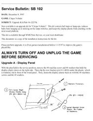
- Page 17 and 18: GAME OPERATION &cAUTION After assem
- Page 19 and 20: Press the Up or Down buttons to cyc
- Page 21 and 22: B .4 Feature Audits B.4 01 B.4 02 B
- Page 23 and 24: Press the Up or Down buttons to cyc
- Page 25 and 26: T. 4 Solenoid Test The Solenoid Tes
- Page 27 and 28: T.12 Flipper Coll Test Continued .
- Page 29 and 30: Press the Up or Down buttons to cyc
- Page 31 and 32: U. 9 o 8 Install Add·A·Ball This
- Page 33 and 34: Press the Up or Down buttons to cyc
- Page 35 and 36: A.1 18 Maximum Ticket/Player The am
- Page 37 and 38: A.2 Feature Adjustments A.2 01 Buy
- Page 39 and 40: A.2 10 Computer Extra Ball Memory T
- Page 41 and 42: A. 3 Pricing Adjustments A.3 01 Gam
- Page 43 and 44: Pricing Table Country 9o_in Chutes
- Page 45 and 46: A.5 Printer Adjustments (optional b
- Page 47 and 48: Factory Settings Restored. This mes
- Page 49 and 50: Magnet Broken This message is displ
- Page 51 and 52: Fllptronlc II Controller Board Audi
- Page 53 and 54: PLAYFIELD DISASSEMBLY Removing the
- Page 55 and 56:
.l:llm Qucrlptlon 1. Diverter Ramp
- Page 57 and 58:
SECTION 2 Parts Information DEMOLIT
- Page 59 and 60:
Cabinet Assembly ® ''.-....,,_._..
- Page 61 and 62:
A-16917-50028 Sound Board Assembly
- Page 63 and 64:
A-14039 Dot Matrix Controller Assem
- Page 65 and 66:
t:J ~ ~ ~ ~ ::z: ~ 08 [3 1 1 a~1\i:
- Page 67 and 68:
A·17982 7 Ball Trough LED PCB Asse
- Page 69 and 70:
A-17316 Flipper Opto PCB Assembly 0
- Page 71 and 72:
A-16100·2 Aux. Driver PCB Assembly
- Page 73 and 74:
Flipper Assembly A·15849·L·2 (Sh
- Page 75 and 76:
A-16765·1 Outhole Ball Trough Asse
- Page 77 and 78:
8·9361-R Ball Eject Assembly • A
- Page 79 and 80:
A-15361 Tilt Mechanism Assembly .11
- Page 81 and 82:
A-17597 Elevator Assembly 0 0 DEMOL
- Page 83 and 84:
A-16989 Cryoclaw Assembly DEMOLITIO
- Page 85 and 86:
Control Handle Assembly ± ~ -.i::
- Page 87 and 88:
A-17241 Ramp Diverter Assembly 0 __
- Page 89 and 90:
A-17540 Universal Power Interface A
- Page 91 and 92:
Posts Part Number Description Quant
- Page 93 and 94:
Unique Parts (Continued) Part Numbe
- Page 95 and 96:
UPPER PLAYFIELD PARTS LOCATIONS ltt
- Page 97 and 98:
RUBBER RINGS J.mm pan No. Qlx Descr
- Page 99 and 100:
LAMPS LOCATIONS Lamp Assv ~ Bulb No
- Page 101 and 102:
SWITCH LOCATIONS .11f1m. Switch No.
- Page 103 and 104:
C2lllEl11btu .111.m lW.r. A&sy Ng .
- Page 105 and 106:
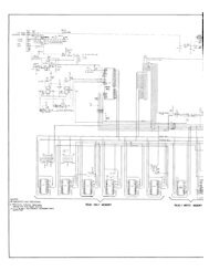
SECTION 3 Schematics, Wiring Diagra
- Page 107 and 108:
Dedicated Switches I I CPU BOARD J2
- Page 109 and 110:
DiverterFlasher Rt. SOLENOID I FLAS
- Page 111 and 112:
' Power Driver PCB 1 1 J 107 ~ 1 Re
- Page 113 and 114:
Elashlamp CjrcyH : POWER DRIVER BOA
- Page 115 and 116:
1 .... U. Flipper Cjrcujt pjagram R
- Page 117 and 118:
Eligoer Cabjnet Switch Circuit p!ag
- Page 119 and 120:
A-16908 LED PCB Assembly (green boa
- Page 121 and 122:
A-17982 7 Ball Trough LED PCB Assem
- Page 123 and 124:
A-15576 7-0pto Switch Board Schemat
- Page 125 and 126:
D.C. Motor Control Assembly A-16120
- Page 127 and 128:
A-15542 Motor EMI PCB Assembly I rn
- Page 129 and 130:
R17 +5VOC VCC L R16 4.7K'1 +50Vpc(A
- Page 131 and 132:
A-17051·1 Coin Door Interface PCB
- Page 133 and 134:
A .. 127 42-50028 CPU Board 0 ..
- Page 135 and 136:
A-15472·1 Fliptronic II Board 1joo
- Page 137 and 138:
Power Driver Board Continued ... J1
- Page 139 and 140:
LAMPS ~ 1 2 Yellow-Brown Yellow-Red