

Hangar 9 P-51 1.50 ARF
Hangar 9 P-51 1.50 ARF
Hangar 9 P-51 1.50 ARF
- No tags were found...

You also want an ePaper? Increase the reach of your titles
YUMPU automatically turns print PDFs into web optimized ePapers that Google loves.
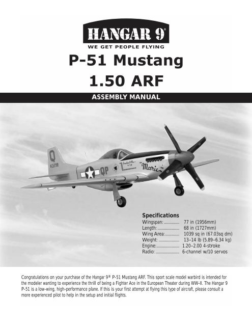
TM®WE GET PEOPLE FLYINGP-<strong>51</strong> Mustang<strong>1.50</strong> <strong>ARF</strong>ASSEMBLY MANUALSpecificationsWingspan: ..............Length: ....................Wing Area:.............Weight: ...................Engine:.....................Radio: ......................77 in (1956mm)68 in (1727mm)1039 sq in (67.03sq dm)13–14 lb (5.89–6.34 kg)1.20–2.00 4-stroke6-channel w/10 servosCongratulations on your purchase of the <strong>Hangar</strong> 9 ® P-<strong>51</strong> Mustang <strong>ARF</strong>. This sport scale model warbird is intended forthe modeler wanting to experience the thrill of being a Fighter Ace in the European Theater during WW-II. The <strong>Hangar</strong> 9P-<strong>51</strong> is a low-wing, high-performance plane. If this is your first attempt at flying this type of aircraft, please consult amore experienced pilot to help in the setup and initial flights.
Table of ContentsTable of Contents . . . . . . . . . . . . . . . . . . . . . . . . . . . . . . . . . . . . . . . . . . . . . . . . . . . . . . . . . . . . . . 2Additional Required Equipment . . . . . . . . . . . . . . . . . . . . . . . . . . . . . . . . . . . . . . . . . . . . . . . . . . . . 3Contents of Kit . . . . . . . . . . . . . . . . . . . . . . . . . . . . . . . . . . . . . . . . . . . . . . . . . . . . . . . . . . . . . . . . 3Additional Required Tools and Adhesives . . . . . . . . . . . . . . . . . . . . . . . . . . . . . . . . . . . . . . . . . . . . . 4Other Items Needed (not included in the kit) . . . . . . . . . . . . . . . . . . . . . . . . . . . . . . . . . . . . . . . . . . 4Warning . . . . . . . . . . . . . . . . . . . . . . . . . . . . . . . . . . . . . . . . . . . . . . . . . . . . . . . . . . . . . . . . . . . . . 4Warranty Information . . . . . . . . . . . . . . . . . . . . . . . . . . . . . . . . . . . . . . . . . . . . . . . . . . . . . . . . . . . . 5Using the Manual . . . . . . . . . . . . . . . . . . . . . . . . . . . . . . . . . . . . . . . . . . . . . . . . . . . . . . . . . . . . . . 5Before Starting Assembly . . . . . . . . . . . . . . . . . . . . . . . . . . . . . . . . . . . . . . . . . . . . . . . . . . . . . . . . 5Section 1: Hinging the Ailerons . . . . . . . . . . . . . . . . . . . . . . . . . . . . . . . . . . . . . . . . . . . . . . . . . . . . 6Section 2: Aileron Servo Installation . . . . . . . . . . . . . . . . . . . . . . . . . . . . . . . . . . . . . . . . . . . . . . . . 8Section 3: Aileron Linkages . . . . . . . . . . . . . . . . . . . . . . . . . . . . . . . . . . . . . . . . . . . . . . . . . . . . . . 12Section 4: Hinging the Flaps . . . . . . . . . . . . . . . . . . . . . . . . . . . . . . . . . . . . . . . . . . . . . . . . . . . . . 14Section 5: Flap Servo Installation . . . . . . . . . . . . . . . . . . . . . . . . . . . . . . . . . . . . . . . . . . . . . . . . . 16Section 6: Flap Linkages . . . . . . . . . . . . . . . . . . . . . . . . . . . . . . . . . . . . . . . . . . . . . . . . . . . . . . . . 20Section 7: Retract Servo Installation . . . . . . . . . . . . . . . . . . . . . . . . . . . . . . . . . . . . . . . . . . . . . . . . 22Section 8: Main Landing Gear and Wheel Doors . . . . . . . . . . . . . . . . . . . . . . . . . . . . . . . . . . . . . . 24Section 9: Joining the Wing . . . . . . . . . . . . . . . . . . . . . . . . . . . . . . . . . . . . . . . . . . . . . . . . . . . . . 28Section 10: Mounting the Wing to the Fuselage . . . . . . . . . . . . . . . . . . . . . . . . . . . . . . . . . . . . . . . 31Section 11: Lower Air Intake Installation . . . . . . . . . . . . . . . . . . . . . . . . . . . . . . . . . . . . . . . . . . . . 32Section 12: Stabilizer Installation . . . . . . . . . . . . . . . . . . . . . . . . . . . . . . . . . . . . . . . . . . . . . . . . . . 34Section 13: Hinging the Elevators . . . . . . . . . . . . . . . . . . . . . . . . . . . . . . . . . . . . . . . . . . . . . . . . . 36Section 14: Hinging the Rudder . . . . . . . . . . . . . . . . . . . . . . . . . . . . . . . . . . . . . . . . . . . . . . . . . . . 38Section 15: Tail Wheel Installation . . . . . . . . . . . . . . . . . . . . . . . . . . . . . . . . . . . . . . . . . . . . . . . . . 39Section 16: Fuel Tank Assembly . . . . . . . . . . . . . . . . . . . . . . . . . . . . . . . . . . . . . . . . . . . . . . . . . . 41Section 17A: Engine Installation (Saito 180GK) . . . . . . . . . . . . . . . . . . . . . . . . . . . . . . . . . . . . . . . 44Section 17B: Engine Installation (Saito 200 TI) . . . . . . . . . . . . . . . . . . . . . . . . . . . . . . . . . . . . . . . 46Section 18: Throttle Pushrod and Fuel Tank . . . . . . . . . . . . . . . . . . . . . . . . . . . . . . . . . . . . . . . . . . 49Section 19: Radio Installation . . . . . . . . . . . . . . . . . . . . . . . . . . . . . . . . . . . . . . . . . . . . . . . . . . . . <strong>51</strong>Section 20: Rudder and Elevator Linkages . . . . . . . . . . . . . . . . . . . . . . . . . . . . . . . . . . . . . . . . . . . 53Section 21: Throttle Linkage Installation . . . . . . . . . . . . . . . . . . . . . . . . . . . . . . . . . . . . . . . . . . . . 57Section 22: Attaching the Cowl . . . . . . . . . . . . . . . . . . . . . . . . . . . . . . . . . . . . . . . . . . . . . . . . . . . 58Section 23: Cockpit Details . . . . . . . . . . . . . . . . . . . . . . . . . . . . . . . . . . . . . . . . . . . . . . . . . . . . . . 58Section 25: Applying the Decals . . . . . . . . . . . . . . . . . . . . . . . . . . . . . . . . . . . . . . . . . . . . . . . . . . 60Section 24: Attaching the Canopy . . . . . . . . . . . . . . . . . . . . . . . . . . . . . . . . . . . . . . . . . . . . . . . . . 60Adjusting the Engine . . . . . . . . . . . . . . . . . . . . . . . . . . . . . . . . . . . . . . . . . . . . . . . . . . . . . . . . . . . 61Control Throws and Center of Gravity . . . . . . . . . . . . . . . . . . . . . . . . . . . . . . . . . . . . . . . . . . . . . . 61Preflight at the Field . . . . . . . . . . . . . . . . . . . . . . . . . . . . . . . . . . . . . . . . . . . . . . . . . . . . . . . . . . . 612
Contents of KitFCBALarge PartsA. HAN2401 Wing Set with JoinerB. HAN2404 FuselageC. HAN2402 Tail SetD. HAN2405 Fiberglass Belly ScoopE. HAN2406 Fiberglass CowlF. HAN2407 Canopy3ED14Small Parts1. HAN2403 Aluminum Stabilizer Tube Set2. HAN2409 Tail Wheel Assembly3. HAN2410 Pushrod Set4. HAN2412 Scale Detail Set2Additional items sold separatelyHAN2408Mechanical Retract SetHAN2411Decal SetAdditional Required EquipmentRadio Equipment• 6-channel radio system (minimum)• 8 standard servos (JRPS537 recommended orequivalent)• 2 Low-Profile Retract Servos (JRPS703)Recommended JR Systems• JR XF652• JR XP783• JR XP8103• PCM 10XJR PCM 10XJR XP8103Recommended Engines• <strong>1.50</strong>–2.18 2-cycle engines• 1.20–2.00 4-cycle engines4-Cycle Engine• Saito 1.80–2.00Saito 200TiSAIE200TISaito 1.80SAIE1803
Additional Required Tools and AdhesivesTools• Drill• Drill Bits: 1/16", 1/8", 3/32", 5/64”, 5/32"• Phillips screwdriver (small, medium)• Pliers• Side Cutters• Moto-tool w/cut-off wheel• Hobby knife with #11 blade• 90-degree triangle• Straight edge• Canopy scissors• Side cutters• Adjustable wrench• Hex wrenchOther Required Items• Mixing sticks for epoxy• Epoxy brushes• Rubbing alcohol• Sanding bar• Sandpaper (medium)• Paper towels• Wax paper• Felt-tipped pen or pencil• Measuring device (e.g. ruler, tape measure)• T-pins• String• Radio packing foam• Petroleum jellyAdhesives• Thin CA (cyanoacrylate) glue• Thick CA (cyanoacrylate) glue• CA remover/debonder• 6-minute epoxy• 30-minute epoxy• Pacer Z-42 Threadlock• Canopy glue (RC-56)• Masking tape (3M blue recommended)Other Items Needed (not included in the kit)• Propeller (consult your engines instruction manual)• 24” Servo Lead Extension (JRPA102)• 6” Servo Lead Extension (JRPA094)• Large servo arm (JRPA212) (2)• Propeller (consult your engines instruction manual)• 5" P-<strong>51</strong> SpinnerWarningAn RC aircraft is not a toy! If misused, it can cause serious bodily harm and damage to property. Fly only in open areas,preferably at AMA (Academy of Model Aeronautics) approved flying sites, following all instructions included with yourradio and engine.4
Before Starting AssemblyBefore beginning the assembly of your P-<strong>51</strong>, remove each part from its bag for inspection. Closely inspect thefuselage, wing panels, rudder, and stabilizer for damage. If you find any damaged or missing parts, contact theplace of purchase.If you find any wrinkles in the covering, use a heat gun or covering iron to remove them. Use caution while workingaround areas where the colors overlap to prevent separating the colors.Using the ManualThis manual is divided into sections to help make assembly easier to understand, and to provide breaks betweeneach major section. In addition, check boxes have been placed next to each step to keep track of each stepcompleted. Steps with two boxes indicate that the step will require repeating, such as for a right or left wing panel,two servos, etc. Remember to take your time and follow the directions.Warranty InformationHorizon Hobby, Inc. guarantees this kit to be free from defects in both material and workmanship at the date ofpurchase. This warranty does not cover any parts damage by use or modification. In no case shall Horizon Hobby'sliability exceed the original cost of the purchased kit. Further, Horizon Hobby reserves the right to change or modifythis warranty without notice.In that Horizon Hobby has no control over the final assembly or material used for the final assembly, no liabilityshall be assumed nor accepted for any damage of the final user-assembled product. By the act of using the product,the user accepts all resulting liability.Once assembly of the model has been started, you must contact Horizon Hobby, Inc. directly regarding any warrantyquestion that you have. Please do not contact your local hobby shop regarding warranty issues, even if that is whereyou purchased it. This will enable Horizon to better answer your questions and service you in the event that you mayneed any assistance.If the buyer is not prepared to accept the liability associated with the use of this product, the buyer is advised toreturn this kit immediately in new and unused condition to the place of purchase.Horizon Hobby4105 Fieldstone RoadChampaign, Illinois 61822(217) 355-9<strong>51</strong>1www.horizonhobby.com5
Section 1: Hinging the AileronsRequired Parts• Right and left wing panels w/ailerons• CA hinges (6)Required Tools and Adhesives• Thin CA glue • CA remover/debonder• Paper towel • T-PinsStep 3Slide the aileron onto the wing until there is only aslight gap between the aileron and wing panel. Removethe T-pins and snug the aileron against the wing panel.Slide the aileron towards the wing tip until there is onlya 1/32" gap between the end of the aileron and wing tip.Step 1Carefully remove the tape holding the aileron to the wing.Locate the hardwood control horn mount in the aileron.The center of the mount is located 7 11 / 16 " inches fromthe tip end of the aileron (narrow end). The plate is1 1 / 4 " wide and 1" deep.Step 2Locate three of the large CA hinges and place a T-pin inthe center of the hinge as shown. Slide each of the threehinges into the aileron so the T-pin is resting against theleading edge of the aileron.Note: Do not use CA accelerator during thehinging process. The CA must be allowed tosoak into the hinge to provide the best bond.Using accelerator will not provide enough timefor this process.Step 4Deflect the aileron and apply thin CA to the hinge. Applyenough CA to completely saturate the hinge. Use carenot to deflect the aileron so it pulls away from the wing.When the hinge is glued in place, there should be nomore than a 1/32" hinge gap maintained throughoutthe length of the aileron.6
Section 1: Hinging the AileronsStep 5Turn the wing panel over, deflect the aileron in theopposite direction and apply thin CA to the other sideof the hinges as described in the previous step. Makesure the thin CA penetrates completely into both theaileron and wing panel.Step 7Firmly grasp the wing and aileron and gently pull onthe aileron to ensure the hinges are secure and cannotbe pulled apart. Use caution when gripping the wingand aileron to avoid crushing the structure.Step 6Use CA remover/debonder and a paper towel to removeany excess CA accumulated on the wing or aileronsurface. Allow time for the CA to completely curebefore moving to the next step.Step 8Work the aileron up and down several times to work inthe hinges and check for proper movement.Step 9Repeat Steps 1 through 8 for the remaining aileron.7
Section 2: Aileron Servo InstallationRequired Parts• Wing assembly• Aileron servos w/mounting hardware (2)• Servo hatch screws (#2 x 3/8") (4)• Large Servo Arm (JRPA212) (1 pkg)• Servo mounting blocks (4)• 24" Servo Lead Extension (JRPA102)• Aileron servo hatch (2)Step 2Install the recommended servo hardware (grommets andeyelets) supplied with the servo. Temporarily install along half servo arm (JRPA212) onto the servo andposition the servo onto the hatch so the servo arm iscentered in the notch. Also ensure the servo arm does notextend past the edge of the servo hatch. Once satisfied,mark the location for the servo mounting blocks.Required Tools and Adhesives• Phillips screwdriver • Felt-tipped pen• String/dental floss • Ruler• Drill Bit: 1/16", 5/64" • Drill• 6-minute epoxyStep 1Locate the aileron hatch. The slot for the aileron horn ispositioned towards the trailing edge of the wing andtowards the wing tip as shown.Step 3Locate the servo mounting blocks. Use 6-minuteepoxyto glue them in place on the marks made inthe previous step. Let the epoxy fully cure beforeproceeding to the next step.Note: The aileron servo is mounted directlyto the hatch.8
Section 2: Aileron Servo InstallationStep 4Place the aileron servo between the mounting blocks anduse a felt-tipped pen to mark the location of the fourservo mounting screws. Note that the servo must nottouch the hatch in order to isolate engine vibration.Photo for Step 5Note: Before mounting the servo, it issuggested to electronically center the servousing the transmitter, then install the servoarm to avoid having to remove the servo andcenter the arm later. It may be necessary toslightly trim one of the servo mountingblocks to clear the servo wire.Step 6Connect a 24" Servo Lead extension (JRPA212) to theservo lead. Secure the connectors by tying them in a knotusing dental floss (as shown) or by using a commerciallyavailable connector clamp to prevent the servo leads frombecoming disconnected.Step 5Remove the servo and use a 1/16" drill bit to predrillthe holes for the servo mounting screws marked in theprevious step. Use the screws supplied with the servoto mount it to the servo mounting blocks.Note: It is always a good idea to secure theservo connector and servo extension togetherto prevent the wires from becoming unpluggedinside the wing.9
Section 2: Aileron Servo InstallationStep 7Use a piece of string with a small weight (such as a wheelcollar) attached as a device to pull the servo lead throughthe wing. Lower the weight through the opening at theroot of the wing as shown.Photo for Step 9Step 8Stand the wing on the tip and allow the weight to dropthrough the wing until it appears in the opening for theservo leads. It may require a little help to pass by thewing ribs in the form of slightly shaking the wing.Photo for Step 9Step 10Place the hatch cover in position in the aileron opening.Measure in 1/8" on all four sides of the hatch. Drill four1/16" holes at the intersections of the lines as shown.Note: Drill through the servo hatch and theunderlying hatch mounts. Use caution not toaccidentally drill through the top of the wing.Step 9Tie the string onto the servo extension. Gently pull theextension through the wing using the string. Untie thestring when the servo lead has been pulled through. Usetape to secure the servo lead to the wing to prevent itfrom falling back into the wing panel.10
Section 2: Aileron Servo InstallationStep 11Remove the servo hatch cover and re-drill the holes usinga 5/64" drill bit. Use 2–3 drops of thin CA to harden theunderlying wood. This will prevent the screws fromcrushing the wood when they are tightened. Secure thehatch using four #2 x 3/8" screws.Photo for Step 11Photo for Step 11Step 12Repeat Steps 1 through 11 for the remainingaileron servo.11
Section 3: Aileron LinkagesRequired Parts• Wing assembly • Control horn (2)• Mounting screws (6) • Metal clevis (4)• Clevis keeper (4) • 4-40 x 2" threaded rod (2)• 4-40 nuts (4) • #2 x 3/8" screws (6)Step 3Remove the back plate from the control horn using sidecutters or a sharp hobby knife. Use a 5/64" drill bit to drillout the mounting holes in the control horn.Required Tools and Adhesives• Thin CA• Phillips screwdriver• Drill Bit: 1/16", 5/64" • Drill• Felt-tipped penStep 1Prepare the 4-40 aileron linkage by placing the cleviskeepers onto the metal clevises. Thread a 2-56 nut ontoeach end of the 4-40 x 2" threaded rod. Thread a clevisonto each end of the threaded rod. The threaded rodshould just be visible between the forks of the clevis.Step 4Position the control on the aileron by aligning the holesof the control horn with the hinge line of the aileron andcenter on the horn mounting plate (as marked back inSection 1). Use a felt-tipped pen to transfer the mountingholes from the control horn onto the aileron.Step 2Attach the assembled control linkage to theaileron servo arm.12
Section 3: Aileron LinkagesStep 5Drill three 1/16" holes at the locations marked in theprevious step. The holes only need to be 5/16" deep;don’t drill through the top of the aileron.Step 7Attach the control horn using three #2 x 3/8" screws.Step 6Install one of the #2 x 3/8" screws into a hole drilled,then remove it. Place 2-3 drops of thin CA into thehole to harden the wood. This will eliminate thepotential of the screw pulling out of the wood. Repeatthis for each of the three holes.Step 8Attach the aileron control linkage to the aileroncontrol horn.Note: The linkage will be adjusted in Section18: Radio InstallationStep 9Repeat Steps 1 through 8 for the remaining aileronservo linkage.13
Section 4: Hinging the FlapsRequired Parts• Wing assembly • Nylon flap hinges (6)Required Tools and Adhesives• 30-minute epoxy • Paper towels• Rubbing alcohol • Petroleum jellyStep 3Locate the holes in the wing and flap for the flap hinges.Remove the covering if necessary from each hole. Therewill be a total of three holes each in the wing and flap.Step 1Carefully remove the tape holding the flap to the wing.Locate the hardwood control horn mount in the flap. Thecenter of the mount is located 5" from the root of the flap(wide end). The plate is 1 1 / 4 " wide and 1" deep.Step 2Locate three of the nylon flap hinges. Apply a smallamount of petroleum jelly to the hinge joint to prevent theepoxy from preventing movement of the hinge.14
Section 4: Hinging the FlapsStep 4Install the hinges in the flap and slide the flap intoposition. Check to make sure the flap aligns withboth the aileron and wing trailing edge. If it does not,enlarge the first 1/4" of the hinge holes in both thewing and flap to provide more clearance for the centerof the hinge. This will allow the flap to be positionedcloser to the wing for alignment.Step 5Use 30-minute epoxy to install the hinges. Apply epoxyto both the holes in the flap and wing using a toothpick.Apply a light coat of epoxy to the hinge. Slide the flapinto position, and move it up and down to make sure thehinges are aligned. Use tape around the division betweenthe flap and wing, as well as the flap and aileron, to holdthe flap until the epoxy fully cures.Step 6Repeat Steps 1 through 5 for the remaining flap.15
Section 5: Flap Servo InstallationRequired Parts• Wing assembly• Flap servos w/mounting hardware (2)• Servo hatch screws (#2 x 3/8") (4)• Large Servo Arm (JRPA212) (1 pkg)• Servo mounting blocks (4)• 6" Servo Lead Extension (JRPA094)• Flap servo hatch (2)Step 2Install the recommended servo hardware (grommets andeyelets) supplied with the servo. Temporarily install along half servo arm (JRPA212) onto the servo andposition the servo onto the hatch so the servo arm iscentered in the notch. Also ensure the servo arm does notextend past the edge of the servo hatch. Once satisfied,mark the location for the servo mounting blocks.Required Tools and Adhesives• Thin CA• Thick CA• Phillips screwdriver • Felt-tipped pen• Drill Bit: 1/16", 5/64" • Drill• String/.dental flossStep 1Locate the flap hatch. The slot for the flap horn ispositioned towards the trailing edge of the wing, aswell as towards the tip, as shown in the photo.16
Section 5: Flap Servo InstallationStep 3Locate the servo mounting blocks. Use 6-minuteepoxyto glue them in place on the marks made inthe previous step. Let the epoxy fully cure beforeproceeding to the next step.Step 5Remove the servo and use a 1/16" drill bit to predrillthe holes for the servo mounting screws marked in thepervious step. Use the screws supplied with the servoto mount it to the servo mounting blocks.Step 4Place the flap servo between the mounting blocksand use a felt-tipped pen to mark the location of thefour mounting screws.Note: The servo must not touch the hatch inorder to isolate engine vibration.Step 6Before installing the servo arm, center the servoelectronically using the transmitter. Install the servoarm so it is positioned towards the rear of the servohatch (trailing edge) when the transmitter is in the “upflap” position. Check the movement of the servo, theninstall the servo arm screw.17
Section 5: Flap Servo InstallationStep 7Connect a 6" Servo Lead extension (JRPA094) to theservo lead. Secure the connectors by tying them in aknot using dental floss (as shown) or by using acommercially available connector clamp to preventthe servo leads from becoming disconnected.Step 9Stand the wing on the tip and allow the weight to dropthrough the wing until it appears in the opening for theservo leads. It may require a little help to pass by thewing ribs in the form of slightly shaking the wing.Note: It is always a good idea to secure theservo connector and servo extension togetherto prevent the wires from becoming unpluggedinside the wing.Step 8Use a piece of string with a small weight (such as awheel collar) attached as a device to pull the servo leadthrough the wing. Lower the weight through the openingat the root of the wing as shown.Step 10Tie the string onto the servo extension. Gently pull theextension through the wing using the string. Untie thestring when the servo lead has been pulled through. Usetape to secure the servo lead to the wing to prevent itfrom falling back into the wing panel.18
Section 5: Flap Servo InstallationStep 11Place the hatch cover into position in the flap opening.Measure in 1/8" on all four sides of the hatch. Drill four1/16” holes at the intersections of the lines as shown.Step 12Remove the servo hatch cover and re-drill the holes usinga 5/64" drill bit. Use 2–3 drops of thin CA to harden theunderlying wood. This will prevent the screws fromcrushing the wood when they are tightened. Secure thehatch using four #2 x 3/8" screws.Note: Drill through the servo hatch and theunderlying hatch mounts. Use caution not toaccidentally drill through the top of the wing.Step 13Repeat Steps 1 through 12 for the remaining flap servo.19
Section 6: Flap LinkagesRequired Parts• Wing assembly • Control horn (2)• Mounting screws (6) • Metal clevis (4)• Clevis keeper (4) • 4-40 nuts (4)• 4-40 x 1-1/2" threaded rod (2)• #2 x 3/8” screws (6)Step 3Remove the back plate from the control horn using sidecutters or a sharp hobby knife. Use a 5/64" drill bit to drillout the mounting holes in the control horn.Required Tools and Adhesives• Thin CA• Phillips screwdriver• Drill Bit: 1/16", 5/64" • Drill• Felt-tipped penStep 1Prepare the flap linkage by placing the clevis keepers ontothe metal clevises. Thread a 4-40 nut onto each end of the4-40 x 1-1/2" threaded rod. Thread a clevis onto each endof the threaded rod. The threaded rod should just bevisible between the forks of the clevis.Step 4Position the control horn on the flap by: Aligning the frontedge of the control horn 1/2" behind the trailing edge ofthe wing and in-line with the flap control linkage. Use afelt-tipped pen to transfer the mounting holes from thecontrol horn onto the flap.Step 2Attach the assembled linkage to the flap servo arm.20
Section 6: Flap LinkagesStep 5Drill three 1/16" holes at the locations marked in theprevious step. The holes only need to be 5/16" deep;don’t drill through the top of the flap.Step 7Attach the control horn using three #2 x 3/8" screws.Step 8Attach the flap control linkage to the flap control horn.Step 6Install one of the #2 x 3/8" screws into a hole drilled,then remove it. Place 2–3 drops of thin CA into thehole to harden the wood. This will eliminate thepotential of the screw pulling out of the wood. Repeatthis for each of the three holes.Note: The linkage will be adjusted in Section18: Radio Installation.Step 9Repeat Steps 1 through 8 for the remaining flapservo linkage.21
Section 7: Retract Servo InstallationRequired Parts• 4-40 x 10-1/2" threaded rod (2)• Right and left wing panels• Retract servo with hardware (2) (JRPS703)• Easy connector (2) • Connector back plate (2)• 4-40 x 1/4" screw (2) • Metal clevis (2)• Clevis keeper (2) • 4-40 nut (2)Required Tools and Adhesives• Threadlocking compound• Drill Bit: 1/16", 7/64" • Drill• Phillips screwdriver • 3/32" hex wrench• Hobby knife • Side cutters• Felt-tipped penNote: The retract mechanism for the P-<strong>51</strong>comes preinstalled from <strong>Hangar</strong> 9 ® . The P-<strong>51</strong>retract system is designed to use low-profileretract servos, such as the JRPS703.Photo for Step 5Step 3Connect the clevis to the retract actuator lever. Slidethe clevis keeper onto the clevis to prevent the clevisfrom opening up during flight. Apply a small amount ofthreadlocking compound behind the clevis, then tightenthe nut against the clevis. This will prevent the threadedrod from rotating in the clevis, which could lead tofailure in flight.Step 1Remove the retract from the wing by removing the four#2 x 3/8" screws that hold the retract in position.Step 4Cut the threaded rod to a length of 9 1 / 2 ”. Make a slightbend as shown in the photo to make the installation of theretract in the next step easier.Step 2Prepare the retract linkage by threading a 4-40nut ontothe shaft. Slide a clevis keeper onto the metal clevis, thenthread the clevis onto the 4-40 x 10 1 / 2 " threaded rod.The threads of the threaded rod should be visible betweenthe forks of the clevis.22
Section 7: Retract Servo InstallationStep 5Re-install the retract back into the wing. Guide theretract pushrod through the wing and into the openingfor the retract servo. Secure the retract using thescrews removed in Step 1.Step 8Using a ruler, locate a hole in the servo arm that is1/2” away from the center on the arm. Drill the holelarger using a 7/64" drill bit.Step 6Install the servo mounting hardware included with yourretract servo, (rubber grommets and eyelets). With theservo wheel removed, install the servo as shown, with theoutput shaft towards the root of the wing.Step 9Locate an easy connecter and an easy connector backplate. Install the connector in the hole drilled in theprevious step. Secure the connector position usingthe connector back plate.Step 10Connect the retract servo to your radio system andelectronically move the servo to the retracted position.Slide the retract control wire through the easy connectoras shown and secure the servo wheel to the retract servo.Step 7With the servo in place, use a 1/16" drill bit to drill thepilot holes for the servo mounting screws. Secure theretract servo using the screws supplied with the servo.Caution: Drill only deep enough for themounting screws. If you drill too deep, the bitwill come out through the bottom of the wing.23
Section 7: Retract Servo InstallationStep 11With the retract servo in the retracted position, push theretract linkage to manually retract the landing gear. Installa 4-40 x 1/4" screw into the easy connector and tighten itto secure the retract linkage.Photo for Step 12Photo for Step 12Step 12Cycle the retract system several times to make sure thereis no binding. Also check to verify the gear locks inboth the extended and retracted positions. Make anynecessary adjustments to be sure the retracts areworking and locking correctly.Step 13Repeat Steps 1 through 12 for the remaining retract.Section 8: Main Landing Gear andWheel DoorsRequired Parts• Wing assembly • Landing gear door (2)• Wheel collars (4) • M3 x 8 screw (4)• Axle mounts (2) • Axles (2)• 6-32 set screw (2) • 8-32 set screw (2)• #4 x 7/16" screws (8)• Main landing gear wheels (2)• Landing gear door mounts (2)Step 1Slide the two landing gear door mounts onto thelanding gear strut. The position of the mounts willbe determined later.Required Tools• Felt-tipped pen • Phillips screwdriver• Drill Bit: 1/8" • Drill• Moto-tool w/cut-off wheel• Threadlocking compound24
Section 8: Main Landing Gear and Wheel FairingsStep 2Slide the axle mount onto the landing gear strut. Apply adrop of thread locking compound onto a 6-32 set screw.Secure the axle mount using the 6-32 set screw, makingsure to tighten the screw onto the flat spot on the strut.Step 4Slide a wheel collar onto the axle. Position the wheelcollar against the axle mount, and then secure its locationusing an M3 x 8 screw.Step 3File a flat spot onto the axle. Slide the axle into the axlemount. Apply a drop of thread locking compound onto an8-32 set screw. Use the set screw to secure the axle.Make sure to tighten the set screw onto the flat spot.Step 5Slide the wheel onto the axle. Make sure the wheel canrotate freely on the axle. Slide another wheel collar ontothe axle and use an M3 x 8 screw to finish up the step.Remember to file a flat spot on the axle, as well as usethreadlocking compound.Step 6Remove the excess axle beyond the wheel collar usinga Moto-tool w/cut-off wheel25
Section 8: Main Landing Gear and Wheel FairingsStep 7Check the fit of the wheel in the wheel well when thegear is retracted. Make any necessary adjustments sothe wheel does not rub the wheel well when the gearis retracted or extended.Step 9Draw two small marks on the landing gear door that willindicate the location of the landing gear strut. Mark thelanding gear where the lower edge of the landing geardoor will be positioned.Step 8Locate the correct landing gear door tape it into position.The correct door will fit the contour of the airfoil and havea small protrusion towards the leading edge of the wing.Step 10Remove the landing gear door and draw a line connectingthe two marks on the back of the door.26
Section 8: Main Landing Gear and Wheel FairingsStep 11Position the gear door mounts as follows: Position mountnear the wheel so it is almost touching the wheel well.Position the mount near the retract mechanism slightlybelow the wheel well.Photo for Step 14Step 15Secure the landing gear door to the mounting bracketsusing four #4 x 7/16" screws.Step 12Extend the retract. Position the landing gear door so thecenterline and lower edge marks are aligned. Mark thescrew locations for the landing gear door mount screws.Step 14Drill the locations marked in the previous step usinga 1/8" drill bit.Step 16Move the landing gear to the retracted position. Check thefit of the landing gear door and make any adjustments toprovide a perfect fit.27
Section 8: Main Landing Gear and Wheel FairingsStep 17Once the landing gear door has been adjusted, movethe retracts to the extended position. Apply a few dropsof thin CA to the mounts to lock in their positions onthe landing gear strut.Step 18Apply a few drops of thick CA to the screws to preventthem from loosening during flight. You may also want totrim off the excess screw for a cleaner look.Step 19Repeat Steps 1 through 18 for the remaining retract.Section 9: Joining the WingRequired Parts• Wing assembly • Wing joiner• Wing dowels (2)Required Tools and Adhesives• Ruler• Masking Tape• 5-minute epoxy • 30-minute epoxy• Rubbing alcohol • Paper towelsStep 2Glue the dowel into the wing using 5-minute epoxy. Applyepoxy to both the holes in the wing and dowels. Slide thedowels in up to the line drawn in the previous step. Cleanup any excess epoxy using a paper towel and rubbingalcohol. Allow the epoxy to fully cure before proceeding.Step 1Locate the two 1/4" x 2" wing dowels. Draw a line 5/8"from one end on each dowel.28
Section 9: Joining the WingStep 3Locate the wing joiner and mark a centerline on the joiner.Step 5With the wing panels together, check for correctdihedral. Place the wing on a large flat surface withone panel resting flat on the surface. The oppositewing tip should be 7 3 / 8 " from the work surface.Once satisfied with the fit, separate the wing panelsand remove the wing joiner.Step 4Without using any glue, test the fit of the wing panels andwing joiner. The panels must fit together without anygaps, top or bottom. If any gaps do exist, use a sandingbar to lightly sand the root ribs of both panels until thepanels fit together perfectly.Note: Read through the remaining steps ofthis section before mixing any epoxy.Hint: It is extremely important to use plenty ofepoxy when joining the wing panels. It willalso be helpful to use wax paper under thewing joint to avoid gluing the wing to yourwork surface.Step 6Mix approximately 1 ounce of 30-minute epoxy. Using anepoxy brush, apply a generous amount of epoxy to thewing joiner cavity of one wing panel.29
Section 9: Joining the WingStep 7Completely coat one half of the wing joiner with epoxy upto the line drawn in Step 1. Be sure to apply epoxy to thetop and bottom of the joiner also. Insert the epoxy coatedside of the joiner into the wing joiner cavity up to themark on the joiner. If you have used enough epoxy, it willooze out of the cavity as the joiner is installed.Step 10Apply epoxy to root wing rib of both panels.Step 8Apply a generous amount of epoxy to the joiner cavity ofthe opposite wing panel.Step 11Carefully slide the wing panels together. Apply enoughpressure to firmly seat the two wing panels together,causing any excess epoxy to ooze out from between thepanels. Use rubbing alcohol and a paper towel to removethe excess epoxy. Check to make sure there are no visiblegaps between the panels.Step 9Apply epoxy to the exposed portion of the wing joiner.Step 12Use masking tape to securely hold the wing panelstogether. Place the wing assembly back onto the worksurface (covered with wax paper) and check the dihedralangle. Allow the epoxy to fully cure before continuingto the next section.30
Section 10: Mounting the Wing tothe FuselageRequired Parts• Assembled wing • Fuselage• Plywood wing bolt plate (2)• 1/4-20 x 2" nylon bolts (2)Required Tools and Adhesives• 6-minute epoxy • Screwdriver (slotted)• Hobby knife • Felt-tipped penStep 3Mix 1/2 ounce of 6-minute epoxy and coat both the wingand plywood plate. Align the plate back onto the wing andclamp it in position. Remove any excess epoxy usingpaper towels and rubbing alcohol.Step 1Locate the plywood wing bolt plate. Align the plate alongthe centerline of the wing and trailing edge. Trace aroundthe plate using a felt-tipped pen.Caution: Use scrap plywood under the clampsto prevent damage to the balsa wing structure.Hint: The hole in the wing and hole in theplate should line up when positioned correctly.Step 2Use a hobby knife with a brand new blade to removethe covering 1/16" inside of the line drawn. Use carenot to cut into the underlying balsa, as this willweaken the wing structure.Step 4Once the epoxy has fully cured, repeat Steps 1 through 3for the remaining wing bolt plate.Step 5Place the wing onto the fuselage, and check the fit. Makeany adjustments necessary to the wing bolt holes andattach the wing using the two 1/4-20 x 2" nylon bolts.31
Section 11: Lower Air Intake InstallationRequired Parts• Air scoop • Plastic guide tubes (2)• Plywood tube locators (2)Step 3Place a piece of wax paper between the fuselage andwing, then bolt the wing onto the fuselage.Required Tools and Adhesives• Medium CA • Thick CA• Razor saw• Hobby knife• Felt-tipped pen • Medium grit sandpaperStep 1Use a felt-tipped pen to trace around the heads ofthe wing bolts.Step 4Use medium grit sandpaper to lightly sand the insideedge of the air scoop.Step 2Remove the wing bolts from the wing. Locate theplywood tube locators and use medium CA to glue thelocators in position. Use the lines drawn around thebolt heads as a guide.32
Section 11: Lower Air Intake InstallationStep 5Position the air scoop onto the wing bolt plates. Itshould fit snug onto the plates. Remove the air scoop,and apply a thin bead of medium CA around the bottomedge of the air scoop. Place it back into position andallow the CA to cure before proceeding.Step 7Remove the wing bolts from the plane by sliding them outthrough the tubes. Remove the tubes and roughen themusing medium sandpaper.Step 6Remove the wing from the fuselage.Try to keep the wingbolts in the wing. Once the wing is removed, slide theplastic guide tubes through the scoop and over the headsof the wing bolts. The ends of the tubes will lock into theplywood tube locators when fully installed.Step 8Apply a thin bead of thick CA around one end of thetubes. Slide the tube in position through the air scoopand into the plywood tube locators. Use a paper towelto clean up any excess CA from the air scoop.33
Section 11: Lower Air Intake InstallationStep 9Remove the excess tube using a razor saw andhobby knife.Section 12: Stabilizer InstallationRequired Parts• Fuselage• Stabilizer tube (short)• #2 x 3/8" screw (2)Required Tools• Drill Bit: 3/32"• Phillips screwdriver• Stabilizer (right and left)• Stabilizer tube (long)• DrillStep 1Locate both of the stabilizer tubes, short and long. Slidethe tubes into one half of the stabilizer as follows: shorttube towards the leading edge and the long tube towardsthe trailing edge.34
Section 12: Stabilizer InstallationStep 2Slide the tubes into the fuselage. The hole in the stabilizerfaces the bottom of the plane.Step 4Use a 3/32" drill bit to drill through the hole in thestabilizer into the stabilizer tube. Be very careful to onlydrill through the tube, not through the top of the stabilizer.Step 3Slide the remaining stabilizer half onto the tubes.Step 5Secure the tube in the one stab half using a#2 x 3/8" screw.Step 6Repeat Steps 4 and 5 for the remaining stab half.35
Section 13: Hinging the ElevatorsRequired Parts• Stabilizer• Elevator (right and left)• CA hinges (6)Required Tools and Adhesives• T-Pins• Thin CA• Paper towels • CA remover/debonderStep 3Slide the elevator onto the stabilizer until there is onlya slight gap between the stabilizer and elevator. Removethe T-pins and snug the elevator against the stabilizer.Position the elevator so the tip aligns with the tipof the stabilizer.Step 1Locate the hardwood control horn mount in the elevator.The mount is located at the root end, and is 1 9 / 16 "long and 7/8" wide. This plate must be located towardsthe bottom of the plane.Note: Do not use CA accelerator during thehinging process. The CA must be allowed tosoak into the hinge to provide the best bond.Using accelerator will not provide enough timefor this process.Step 2Locate three of the large CA hinges and place a T-pin inthe center of the hinge as shown. Slide each of the threehinges into the elevator so the T-pin is resting against theleading edge of the elevator.Step 4Deflect the elevator and apply thin CA to the hinge.Apply enough CA to completely saturate the hinge. Usecarenot to deflect the elevator so it pulls away fromthe stabilizer. When the hinge is glued in place, thereshould be no more than a 1/32” hinge gap maintainedthroughout the length of the elevator.36
Section 13: Hinging the ElevatorsStep 5Turn the fuselage over, deflect the elevator in theopposite direction, and apply thin CA to the otherside of the hinges as described in the previous step.Make sure the thin CA penetrates completely intoboth the elevator and stabilizer.Step 7Firmly grasp the elevator and stabilizer and gently pullthem apart to ensure the hinges are secure and cannot bepulled apart. Use caution when gripping them to avoidcrushing the structure.Step 6Use CA remover/debonder and a paper towel to removeany excess CA accumulated on the stabilizer or elevatorsurface. Allow time for the CA to completely cure beforemoving to the next step.Step 8Work the elevator up and down several times to work inthe hinges and check for proper movement.Step 9Repeat Steps 1 through 8 for the remaining elevator.37
Section 14: Hinging the RudderRequired Parts• Fuselage assembly • Rudder• CA hinges (3)Required Tools and Adhesives• T-Pins• Thin CA• Paper towels • CA remover/debonderStep 2Slide the rudder onto the fin. Align the top of the rudderwith the top of the fin. Remove the T-pins and usethin CA to glue the hinges into position. Apply CA toboth sides of the hinges.Note: Hinging the rudder follows the sameprocedure as hinging the ailerons andelevators. We’ll save you some reading andcondense this into just a few steps.Step 1Locate three CA hinges and place a T-pin in the center ofeach hinge. Slide the hinges into the rudder.Step 3Clean up any excess CA using CA remover/debonder.Once the CA has fully cured, gently pull on the rudder toensure the hinges are secure. Flex the rudder a few timesto work in the hinges.38
Section 15: Tail Wheel InstallationRequired Parts• Pushrod wire (33-5/8" long)• Nylon clevis • Clevis keeper• Wheel collar (2) • M3 x 8 screw• #2 x 3/8" screw (4) • Tail wheel• Wire tail gear • Tail gear steering arm• Tail wheelRequired Tools and Adhesives• Pliers• 1.5mm hex wrench• Drill Bit: #20 • Drill• File• Side cutters• Threadlocking compoundStep 1Locate the tail wheel. Carefully drill the hole for theaxle using a #20 drill.Step 2File a flat spot on the tail gear wire. Position the flatoff-center slightly as shown in the photo.Step 3Install the 33 5 / 8 " pushrod wire into the pushrod tubeshown. Make sure the threaded end is installed first,leaving the non-threaded end inside the radio area.Hint: Install the pushrod wire through the holein the firewall to avoid bending the wire.39
Section 15: Tail Wheel InstallationStep 4Slide a clevis keeper onto a nylon clevis. Thread theclevis onto the wire a minimum of 10 turns.Step 7Position the steering arm in the center of thepre-installed tail gear mount. Make sure the set screwin the arm is facing forward.Step 5Locate the tail gear steering arm. Use side cutters toremove the outermost hole from the arm.Step 8Slide the tail gear wire through the mount and steeringarm. Position the wire so there is 1/2" between the topof the mount and the first bend in the wire. Tighten theset screw in the arm.Step 6Attach the clevis to the steering arm in the outer hole asshown. Slide the clevis keeper onto the clevis to keep theclevis from opening during flight.40
Section 15: Tail Wheel InstallationStep 9Slide a wheel collar onto the tail gear wire, then the tailwheel. Finally, slide another wheel collar on, and use anM3 x 8 screw to secure the outer collar. Use a littlethreadlocking compound on the screw to prevent it fromvibrating loose in flight.Step 10Secure the tail gear door cover using four#2 x 3/8" screws.Section 16: Fuel Tank AssemblyRequired Parts• Clunk (fuel pickup) • Metal caps (2)• Fuel pickup tubing • Fuel tank• Rubber stopper • M3 x 20 screw• Metal tubes (short and long)Step 1Locate the fuel tank parts.Required Tools and Adhesives• Hobby knife • Phillips screwdriverNote: The stopper provided with the P-<strong>51</strong>has three holes that are not bored completelythrough the stopper. The holes are for thefuel pickup, fill, and vent lines. For theseinstructions only two holes will be used: onefor the fuel pickup and one for the fuel vent.Only open the third hole if you are going touse a separate fill line.41
Section 16: Fuel Tank AssemblyStep 2Locate the rubber stopper. Insert the shorter metal fueltube into one of the holes in the stopper so that anequal amount of tube extends from each side of thestopper. This tube will be the fuel tank pickup thatprovides fuel to the engine.Step 5Slide the vent tube into on of the remaining two holes inthe stopper from the tank (small cap) side.Step 3Slide the smaller cap over the tube on the smaller end ofthe rubber stopper. This end will be inserted into the fueltank. The larger cap is placed on the side of the rubberstopper that makes the cap. Loosely install the M3 x 20screw through the center of the stopper.Step 6Locate the short piece of silicone fuel tubing and thefuel tank clunk. Install the clunk onto one end of thesilicone tubing. Slide the silicone tubing (end oppositethe clunk) onto the fuel tank pickup tube (straight tube)in the stopper.Step 4Bend the longer fuel tube carefully to a 45-degree angleusing your fingers. This will be the fuel tank vent tube.Use care not to kink the tube while bending.42
Section 16: Fuel Tank AssemblyStep 7Carefully insert the stopper assembly into the fuel tank.Note the position of the vent tube; it must be up at the topportion of the fuel tank to function properly. Also, it maybe necessary to shorten the length of the fuel pickuptubing to make sure the clunk does not rub against theback of the fuel tank. You should be able to turn the tankto any attitude and the clunk will fall to the lowest point.(All directions except for having the stopper facing down.)Step 8Tighten the M3 x 20 screw carefully—do not over tighten.This allows the rubber stopper to form a seal by beingslightly compressed, thus sealing the fuel tank opening.Note: If you are planning on installing theSaito 200TI, the fuel tank will be orienteddifferently. Make sure the tank is built so thevent is pointing up with the fuel tank orientedas shown in the picture.Important: Be sure to differentiate betweenthe vent and fuel pickup tube. Once the tank ismounted inside the fuselage, it will be difficultto tell the tubes apart.Note: The fuel tank will be installed ina later section.43
Section 17A: Engine Installation(Saito 180GK)Required Parts• Fuselage • Engine mount (2)• #8 washers (8) • Engine• 8-32 x 1 1 / 4 " screws (8)• 8-32 nylon lock nuts (4)• Plywood engine mount spacers (2)Step 1Locate the engine mount and the associated hardware.Required Tools and Adhesives• Phillips screwdriver • Measuring device• Adjustable wrench • 11/32" socket wrenchNote: There are two engine installations in thisinstruction manual (Section 17A and Section17B). Section 17A covers the installation of theSaito 1.80 Golden Knight (SAIE180GK).Section 17B covers the installation of the Saito200 TI (SAIE200TI).Note: The P-<strong>51</strong> comes with the blind nutspreinstalled in the firewall. They are located forthe installation of the Saito 1.80-size fourstrokes.If you plan on using another engine,you may need to remove the blind nuts anddrill new holes in the firewall for yourparticular engine.Step 2Temporarily install the engine to the rails using four8-32 bolts, four washers and four lock nuts. Leavethe bolts loose enough to allow the engine to slide onthe engine mount.Section 17B covers relocating the blind nutsfor mounting the engine when using an enginemount different than supplied with the kit.Note: The engine mount is embossed with thecorrect orientation for the mounts.44
Section 17A: Engine Installation (Saito 180GK)Step 3Prepare the engine mount for installation by slidingfour 8-32 bolts and washers through the enginemount. Position the plywood engine mount spacersonto the bolts as shown.Step 5Install the spinner back plate and propeller. Position theengine so there is between 1/16" and 1/8" gap betweenthe back plate and fuselage.Step 4Install the engine mount.Step 6Remove the spinner back plate and tighten the screwsholding the engine to the mount. An 11/32" socketwrench will make this task a lot easier.45
Section 17B: Engine Installation(Saito 200 TI)Required Parts• Fuselage• Engine• #8 washers (4) • 8-32 x 1-1/4" screws (4)• Felt-tipped pen • Associated engine mountRequired Tools and Adhesives• Phillips screwdriver • Drill• Adjustable wrench • Socket Wrench: 11/32"• Drill Bit: 1/4" • Measuring deviceStep 2If you must remove the blind nuts, thread an 8-32 boltpartially into the nut. Lightly tap the bolt to pop the blindnut away from the firewall. This will prevent damaging thethreads of the nuts. Trim the cross brace to allow for theremoval of the blind nuts near the top of the fuselage.Step 1Check the fit of the engine mount you are planningon using. You may get lucky and not have to removethe blind nuts.Step 3Measure the distance between the original holes in thefirewall. Make a mark centered right and left and top tobottom using a felt-tipped pen.46
Section 17B: Engine Installation (Saito 200 TI)Important: The stock engine mount is offset1/4" towards the top of the fuselage. Measure1/4" towards the bottom of the fuse and maketwo marks for the horizontal centerline.Step 6Transfer the measurements made in the last step tothe firewall. Remember to divide by two and measurefrom the centerline.Step 4Connect the marks drawn in the previous step. Your newengine mount will centered here the two lines cross.Step 5Measure and record the distance between the holes inyour particular mount. Make sure your mount will becentered correctly when measuring.Note: Another option is to determine thecenter vertically and horizontally of yourmount. Position the mount on the centerlinesand mark the locations of the bolts directlyon the firewall.47
Section 17B: Engine Installation (Saito 200 TI)Step 7Drill the locations for the new bolts using a 1/4" drill bit.Step 9Install any accessories that may be required for yourparticular engine. In the case of the Saito 200TI, aneeded valve must be attached to the mount. Makeany necessary adjustments to the fuselage to provideclearance if required.Step 8Install your particular motor mount using four 8-32 bolts,four washers and the blind nuts removed in Step 2.Step 10Install the engine of your choice at this time. Use themethod described in Step 5 of Section 17A to positionthe engine fore and aft.48
Section 18: Throttle Pushrod and Fuel TankRequired Parts• Fuel tank assembly • Foam: 1/4", 1/2"• Throttle pushrod tube (15")• Throttle pushrod (17 1 / 4 ")• Fuel tubing (red and green)Step 2Test fit the throttle pushrod tube through the firewallandinto the fuselage. Once satisfied with the fit, mix1/4 ounceof 6-minute epoxy and glue the pushrodinto the firewall.Allow the epoxy to fully cure before continuing.Required Tools and Adhesives• Drill Bit: 1/8" • Drill• Felt-tipped pen • Hobby knife• Masking tapeStep 1Determine the proper location for the throttle pushrod.Mark the location with a felt-tipped pen and drill thefirewall for the pushrod tube using a drill and 1/8" drillbit. Remove the engine if necessary.Step 3Trim the throttle pushrod tube so it extends 1" onto theservo tray.49
Section 18: Throttle Pushrod and Fuel TankStep 4Install the throttle pushrod into the tube and connect it tothe throttle arm. You may need to remove the throttlecontrol arm of the carburetor to connect the Z-bendto the throttle arm.Step 6Connect the two pieces of fuel tubing to the fuel tankspickup and vent tubes. Install the fuel tank into thefuselage from the radio compartment. The stopperand fuel tubes will pass through the round hole in thefirewall. Use more foam to hold the tank in place andprotect from vibration.Hint: Connect the red tube to the vent andthe green tube to the pickup.Important: The Saito 200TI will require a newhole drilled in the firewall for the fuel tankstopper and fuel lines.Step 5Wrap the fuel tank with 1/4" foam. Secure the foamusing masking tape.Note: Make the proper connectionsto the engine using the enginemanufacturer’s instructions.50
Section 19: Radio InstallationRequired Parts• Fuselage assembly• Receiver• Switch harness• Foam• Receiver battery• Servos (4) (not included)Note: Place a drop of thin CA onto eachscrew hole to harden the wood around thehole. Allow the CA to fully cure beforeinstalling the servos.Required Tools and Adhesives• Drill Bit: 1/16" • Drill• Thin CA• Hobby knifeStep 1Install the recommended servo hardware (grommets andeyelets) supplied with your radio system onto four servos(elevator (2), rudder and throttle). Temporarily install thefour servos into the openings and mark the location of theservo mounting screws.Step 3Install the servos as shown. The output shaft of thethrottle servos faces rearward, while the remaining servoswill face forward. Secure the servos using the screwsprovided with the servos.Step 2Remove the servos and drill the holes for the servomounting screws using a 1/16" drill bit.Step 4Mount the radio switch in the side of the fuselage. Gluesmall scraps of plywood to the balsa sheeting inside thefuselage to give the screws something to bite into.<strong>51</strong>
Section 19: Radio InstallationStep 5Connect any necessary extensions and Y-harnessesnecessary to connect up the retract, aileron and flapservos. Connect the elevator, rudder and throttleservo leads to the receiver.Step 7Wrap the receiver battery in protective foam as you didthe receiver. Temporarily mount the receiver and batteryinto the fuselage. It may be necessary to relocate thebattery forward or aft to balance the model as describedin the section “Control Throws and Center of Gravity.”Step 6Wrap the receiver in protective foam to prevent damagethat may be cause by engine vibration.Step 8Route the antenna out through the bottom of the fuselageand secure it to the tail wheel with rubber bands.52
Section 20: Rudder and Elevator LinkagesRequired Parts• Fuselage assembly • Pushrod wires (3)• Nylon clevis (3) • Clevis keeper (3)• Nylon wire keepers (4) • Control horns (3)• #2 nuts (6) • #2 x 3/8" screw (6)• #2 x 1 5 / 8 " threaded rods (3)Step 2Slide a clevis keeper onto a nylon clevis. Thread theclevis onto the wire a minimum of 10 turns. Repeat thisstep for both elevators’ linkages and the rudder linkage.Required Tools and Adhesives• Drill Bit: 1/16" and 5/64"• Hobby knife • Thin CA• Felt-tipped pen • Drill• Threadlocking compoundStep 1Slide the rudder and elevator pushrod wires into the tubein the fuselage. Make sure the threaded portion of thewires is on the outside of the plane near the tail group.Step 3Remove the back plate from a control horn using sidecutters or a sharp hobby knife. Use a 5/64" drill bit to drillout the mounting holes in the control horn.53
Section 20: Rudder and Elevator LinkagesStep 4Attach the clevis to the control horn. Position the controlhorn on the elevator so the control rod is straight, andthe holes in the control horn aligns with the hinge lineof the elevator. Mark the position for the mounting holesusing a felt-tipped pen.Step 6Install one of the #2 x 3/8" screws in a hole drilled,then remove it. Place 2-3 drops of thin CA into the holeto harden the wood. This will eliminate the potential ofthe screw pulling out of the wood. Repeat this for eachof the three holes.Step 5Drill three 1/16" holes at the locations marked in theprevious step. The holes only need to be 5/16" deep:don’t drill through the top of the elevator.Step 7Attach the control horn using three #2 x 3/8" screws.Step 8Center the elevator servo electronically using the radiosystem. Install a servo arm onto one of the elevatorservos. Physically place the elevator control surfacein neutral. Mark the pushrod where it crosses theholes in the servo arm.54
Section 20: Rudder and Elevator LinkagesStep 11Slide the wire through the outer hole in the elevator servoarm. Secure the wire using a nylon wire keeper.Photo for Step 8Step 9Bend the wire 90 degrees at the mark made inthe previous stepStep 12Repeat Steps 3 through 11 for the remaining elevator half.Step 13Center the rudder servo electronically using the radiosystem. Install a servo arm onto the rudder servo.Physically place the tail wheel in neutral. Mark thepushrod where it crosses the holes in the servo arm.Step 14Bend the wire 90 degrees at the mark made inthe previous step.Step 10Cut the wire 1/2" above the bend.Step 15Cut the wire 1/2" above the bend.Step 16Slide the wire through the inner hole in the rudder servoarm. Secure the wire using a nylon wire keeper.55
Section 20: Rudder and Elevator LinkagesStep 17Remove the back plate from the last control horn usingside cutters or a sharp hobby knife.Step 18Attach the clevis to the control horn. Position the controlhorn on the rudder so the control rod is straight, and thefront edge of the control horn aligns with the front edge ofthe bevel on the rudder. Mark the position for themounting holes using a felt-tipped pen.Photo for Step 20Photo for Step 20Step 19Drill the locations marked in the last step using a1/16" drill bit. These three holes will be drilled completelythrough the rudder. Take your time, as each holemust be parallel in order to properly mount therudder control horn.Step 21Physically place the rudder control surface inneutral. Mark the pushrod where it crosses the holesin the servo arm.Step 22Bend the wire 90 degrees at the mark made inthe previous stepStep 23Cut the wire 1/2" above the bend.Step 24Slide the wire through the outer hole in the rudder controlhorn. Secure the wire using a nylon wire keeper.Step 20Thread three #2 nuts onto the threaded rods. Slide the rodthrough the control horn, then through the rudder. Attachthe back plate on the opposite side of the rudder as thecontrol horn. Finally, thread three nuts onto the rods.Tighten the nuts, but don’t crush the balsa. Usethreadlocking compound on the nuts to prevent themfrom loosening during flight.56
Section 21: Throttle Linkage InstallationRequired Parts• Easy connector• Connector back plate• M3 x 8 screwRequired Tools and Adhesives• Phillips screwdriver • Pliers• Drill Bit: 3/32" • DrillStep 1Use a 3/32" drill bit to drill out the holes in a servoarm. Attach an easy connector to the arm using aconnector back plate.Step 3Move the throttle stick and trim to low. Check to makesure the carburetor will move to the low position whenoperating the servo. Install an M3 x 8 screw to securethe easy connector to the throttle pushrod. Check themovement of the throttle to verify there is no binding ateither low or high throttle. If there is, make the necessaryadjustment to eliminate any binding. Install the throttleservo arm screw when complete.Step 2Center the throttle stick and trim with both the receiverand transmitter on. Slide the easy connector onto thethrottle pushrod. Install the throttle servo arm in theneutral position as shown.Step 4Use scrap wood to make a brace for the throttle pushrodtube near the servo as shown.57
Section 22: Attaching the CowlRequired Parts• Fuselage assembly• Mounting screws (6)• CowlRequired Tools and Adhesives• Felt-tipped pen • Hobby knife• Moto-tool w/cut-off wheel and sanding drumStep 1Mount the cowl using the #2 screws provided. Makethe appropriate cutouts in the cowl for the mufflerexhaust and engine cooling.Note: If you are using the Saito 200TI, it willbe required to install a baffle inside the cowl todirect air over the rear cylinder. Make the bafflefrom 1/16" balsa. Be sure to fuel-proof thebalsa before flying.Step 2Install the propeller and spinner.Section 23: Cockpit DetailsRequired Parts• Fuselage assembly• Plastic cockpit detail• Painted canopy• Wing assembly• Decal sheetStep 1Cut out and trim the cockpit and exhaust details usinga pair of scissors.Required Tools and Adhesives• Hobby knife • Canopy scissors• Shoe Goo• 6-minute epoxy58
Section 23: Cockpit DetailsStep 2Cut out the instrument panel decal and apply.Step 4Glue the clear gun site into position using6-minute epoxy.Step 3Glue the cockpit details to the fuselage usingShoe Goo or similar type adhesive, using the pictureson thebox as a guide. Use tape to hold the partsuntil the adhesive cures.Step 5Glue the exhaust into position using Shoe Goo.Step 6Glue the guns into position using Shoe Goo.59
Section 24: Attaching the CanopyRequired Parts• Fuselage assembly• CanopyRequired Tools and Adhesives• Canopy scissors• Canopy glue (RC560)Step 1Glue the canopy to the fuselage using RC560 canopyglue. Tape the canopy in place with masking tape andallow the glue to cure overnight.Section 25: Applying the DecalsRequired Parts• Fuselage assembly • Wing assembly• DecalsRequired Tools and Adhesives• Canopy scissors • Hobby knife• Paper towel • Spray bottle• 2–3 drops dish soapStep 2Use the photos on the box to locate the decals. Usea spray bottle with 2–3 drops of dish soap added tothe water and spray both the fuselage and sticky sideof the decal. This will allow you to reposition thedecal if necessary. Once satisfied with the position,use a paper towel to squeegee out the water. Allow thedecal to dry overnight.Step 1Locate the decal sheet and cut out the decals for the P-<strong>51</strong>using a sharp hobby knife and scissors.Note: There may be some clouding under thedecal, but this will go away as the decal dries.60
Control Throws and Center of GravityRecommended CG LocationAn important part of preparing the aircraft for flight isproperly balancing the model. This is especially importantwhen various engines are mounted.Caution: Do not inadvertently skip this step!The recommended Center of Gravity (C.G.) location forthe P-<strong>51</strong> <strong>1.50</strong> is 6 3 / 8 " behind the leading edge of thewing measured at the fuselage sides. If necessary, movethe battery pack or add weight to either the nose or thetail until the correct balance is achieved. Stick-on weightsare available at your local hobby shop and work well forthis purpose.The following control throws offer a good place to startwith your first flights. We recommend only one ratesetting for the P-<strong>51</strong>. As you become more familiar withthe handling of your model, you may wish to add asecond rate setting.Once the control throws for the ailerons and flaps havebeen set, tighten the 4-40 nuts against the clevises toprevent them from loosening during flight. It is alsohighly suggested to use threadlocking compound.Recommended Control ThrowsLow rateHigh rateAileron 1/2" (14°) up 3/4" (18°) up1/2" (14°) down 3/4" (18°) downElevator 5/8" (12°) up 3/4" (15°) up5/8" (12°) down 3/4" (15°) downRudder 1 7 / 8 " (20°) left 2 1 / 2 " (30°) left1 7 / 8 " (20°) right 2 1 / 2 " (30°) rightFlaps 1 1 / 8 " (15°) down 2 1 / 2 " (38°) downPreflight at the FieldStep 1Before each flying session, range-check your radio.This is accomplished by turning on your transmitterwith the antenna collapsed. Turn on the radio in yourairplane. With your airplane on the ground, you shouldbe able to walk 30 paces away from your airplaneand still have complete control of all functions. If not,don’t attempt to fly! Have your radio equipment checkedout by the manufacturer.Step 2Double-check that all controls (aileron, elevator, throttle,rudder) move in the correct direction.Step 3Before you fly, be sure that your batteries are fullycharged per the instructions included with your radio.Adjusting the EngineStep 1Completely read the instructions included with yourengine and follow the recommended break-in procedure.Step 2At the field, adjust the engine to a slightly rich setting atfull throttle and adjust the idle and low-speed needle sothat a consistent idle is achieved.Step 3Before you fly, be sure that your engine idles reliably,transitions and runs at all throttle settings. Onlywhen this is achieved should any plane be consideredready for flight.61
2003 Official AMANational Model Aircraft Safety CodeEffective January 1, 2003Model Flying MUST be in accordance with this Code in order for AMA Liability Protection to apply.GENERAL1) I will not fly my model aircraft in sanctioned events, airshows or model flying demonstrations until it has beenproven to be airworthy by having been previously,successfully flight tested.2) I will not fly my model higher than approximately 400feet within 3 miles of an airport without notifying theairport operator. I will give right-of-way and avoid flyingin the proximity of full-scale aircraft. Where necessary, anobserver shall be utilized to supervise flying to avoidhaving models fly in the proximity of full-scale aircraft.3) Where established, I will abide by the safety rules forthe flying site I use, and I will not willfully anddeliberately fly my models in a careless, reckless and/ordangerous manner.4) The maximum takeoff weight of a model is 55 pounds,except models flown under Experimental Aircraft rules.5) I will not fly my model unless it is identified with myname and address or AMA number, on or in the model.(This does not apply to models while being flownindoors.)6) I will not operate models with metal-bladed propellersor with gaseous boosts, in which gases other than airenter their internal combustion engine(s); nor will Ioperate models with extremely hazardous fuels such asthose containing tetranitromethane or hydrazine.7) I will not operate models with pyrotechnics (any devicethat explodes, burns, or propels a projectile of any kind)including, but not limited to, rockets, explosive bombsdropped from models, smoke bombs, all explosive gases(such as hydrogen filled balloons), ground mounteddevices launching a projectile. The only exceptionspermitted are rockets flown in accordance with theNational Model Rocketry Safety Code or thosepermanently attached (as per JATO use); also those itemsauthorized for Air Show Team use as defined by ASTAdvisory Committee (document available from AMA HQ).In any case, models using rocket motors as a primarymeans of propulsion are limited to a maximum weight of3.3 pounds and a G series motor. (A model aircraft isdefined as an aircraft with or without engine, not able tocarry a human being.)8) I will not consume alcoholic beverages prior to, norduring, participation in any model operations.9) Children under 6 years old are only allowed on theflight line as a pilot or while under flight instruction.RADIO CONTROL1) I will have completed a successful radio equipmentground range check before the first flight of a new orrepaired model.2) I will not fly my model aircraft in the presence ofspectators until I become a qualified flier, unless assistedby an experienced helper.3) At all flying sites a straight or curved line(s) must beestablished in front of which all flying takes place with theother side for spectators. Only personnel involved withflying the aircraft are allowed at or in the front of the flightline. Intentional flying behind the flight line is prohibited.62
2003 Official AMANational Model Aircraft Safety CodeContinued4) I will operate my model using only radio controlfrequencies currently allowed by the FederalCommunications Commission. (Only properly licensedAmateurs are authorized to operate equipment on AmateurBand frequencies.)5) Flying sites separated by three miles or more areconsidered safe from site-to site interference, even whenboth sites use the same frequencies. Any circumstancesunder three miles separation require a frequencymanagement arrangement which may be either anallocation of specific frequencies for each site or testingto determine that freedom from interference exists.Allocation plans or interference test reports shall besigned by the parties involved and provided to AMAHeadquarters. Documents of agreement and reports mayexist between (1) two or more AMA Chartered Clubs, (2)AMA clubs and individual AMA members not associatedwith AMA Clubs, or (3) two or more individual AMAmembers.6) For Combat, distance between combat engagement lineand spectator line will be 500 feet per cubic inch ofengine displacement. (Example: .40 engine = 200 feet.);electric motors will be based on equivalent combustionengine size. Additional safety requirements will be per theRC Combat section of the current CompetitionRegulations.7) At air shows or model flying demonstrations a singlestraight line must be established, one side of which is forflying, with the other side for spectators.8) With the exception of events flown under AMACompetition rules, after launch, except for pilots orhelpers being used, no powered model may be flowncloser than 25 feet to any person.9) Under no circumstances may a pilot or other persontouch a powered model in flight.Organized RC Racing Event10) An RC racing event, whether or not an AMA RuleBook event, is one in which model aircraft compete inflight over a prescribed course with the objective offinishing the course faster to determine the winner.A. In every organized racing event in which contestants,callers and officials are on the course:1. All officials, callers and contestants must properly wearhelmets, which are OSHA, DOT, ANSI, SNELL or NOCSAEapproved or comparable standard while on theracecourse.2. All officials will be off the course except for the starterand their assistant.3.”On the course” is defined to mean any area beyond thepilot/staging area where actual flying takes place.B. I will not fly my model aircraft in any organized racingevent which does not comply with paragraph A above orwhich allows models over 20 pounds unless thatcompetition event is AMA sanctioned.C. Distance from the pylon to the nearest spectator (line)will be in accordance with the current CompetitionRegulations under the RC Pylon Racing section for thespecific event pending two or three pylon course layout.11) RC Night flying is limited to low performance models(less than 100 mph). The models must be equipped witha lighting system that clearly defines the aircraft’s attitudeat all times.63
TM®WE GET PEOPLE FLYING# 5768© 2003, Horizon Hobby, Inc.4105 Fieldstone RoadChampaign, Illinois 61822(217) 355-9<strong>51</strong>1www.horizonhobby.com


