v.S1 Cylindrical Lock Installation Instructions 1.10 - Access Control ...
v.S1 Cylindrical Lock Installation Instructions 1.10 - Access Control ...
v.S1 Cylindrical Lock Installation Instructions 1.10 - Access Control ...

You also want an ePaper? Increase the reach of your titles
YUMPU automatically turns print PDFs into web optimized ePapers that Google loves.
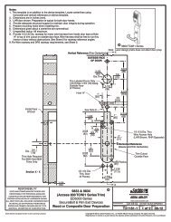
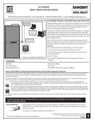
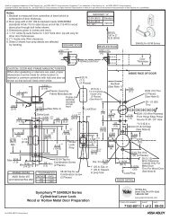
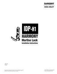
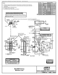
Profile Series v.<strong>S1</strong> PoE <strong>Cylindrical</strong> <strong>Lock</strong>Step #2 – Install StrikeInstall strike in the door frame (Fig.2A).Centerline of LatchFront and Strike(2) #8-32 x 3/4"Latch ScrewsOutside of DoorFig. 2AStep #3 - Install Latchbolt1. Install latch with beveled bolt facing the strike.2. Attach with two screws but DO NOT tightencompletely at this time.IMPORTANT: Latch bevel must match door bevel anddeadlocking latch must stop on strike when door is closed.StrikeDeadlocking LatchFig. 3BCopyright © 2011, Sargent Manufacturing Company, an ASSA ABLOY Group company. All rights reserved.Reproductions in whole or in part without express written permission of Sargent Manufacturing Company is prohibited.Step #4 – Door OptionsA. Fire Stop Plate (P/N 52-0033)Fire-rated doors require a fire stop plate onthe outside of the door (Fig. 4A).1. Drill (2) 1/8" x 1-1/4" deep holes in thedoor if not already present.Refer to template for fire-stopprep locations.2. Attach with flap up andout using (2) #8 x 1/2”self-tapping screws forwood and metal doors.B. Weather Conduit (52-2847)Install weather conduit onNON FIRE-RATED exterior doors only (Fig. 4B).1. Carefully insert the weather conduit into theribbon cable hole on the inside of the door.2. Place the O-ring around the weather conduiton the outside and up against the door (Fig. 4C)Fig. 4AOutside of Door(2) 1/8” DiameterHoles RequiredFire Stop Plate(2) #8 Self-TappingScrews for Woodand Metal Doors(2) Through-bolt HolesRibbon Cable HoleO-RingFig. 3AFig.4C02/11/1112 A7763BFig.4BOutside of Door