v.S1 Cylindrical Lock Installation Instructions 1.10 - Access Control ...
v.S1 Cylindrical Lock Installation Instructions 1.10 - Access Control ...
v.S1 Cylindrical Lock Installation Instructions 1.10 - Access Control ...

You also want an ePaper? Increase the reach of your titles
YUMPU automatically turns print PDFs into web optimized ePapers that Google loves.
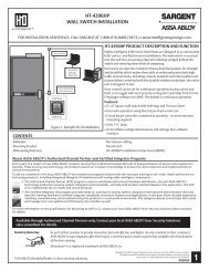
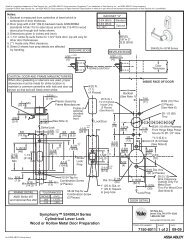
Profile Series v.<strong>S1</strong> PoE <strong>Cylindrical</strong> <strong>Lock</strong>Step #6 - Install <strong>Lock</strong>1. Feed wires into the lock body hole from outside of door (Fig.6A).2. Slide lock body into cross-bore hole from outside (locked side)of the door (Fig. 6B).3. <strong>Lock</strong> body must engage both the latch unit prongsand tail piece (Fig. 6C Detail).IMPORTANT:• Latchbolt screws remain partially tightened.• Door must remain open during installation. Use door stop.• <strong>Lock</strong> body must be centered in the door.Outside<strong>Cylindrical</strong><strong>Lock</strong>Body1Outside of DoorWire Harness(From <strong>Lock</strong> Body)DPSFig. 6ACopyright © 2011, Sargent Manufacturing Company, an ASSA ABLOY Group company. All rights reserved.Reproductions in whole or in part without express written permission of Sargent Manufacturing Company is prohibited.Inside3Fig. 6B DetailLatchbolt Screws(Partially Tightened)Step #7 – Secure the <strong>Lock</strong> to the Door1A. For wood door: Feed wires up through the routedchannel (Fig. 7A).1B. For metal door: Feed wires and connector throughinside of door (not shown).2. Slide inside rose assembly and spacer bushingover lock body and secure with (2) #10-32x1-1/4" through-bolts.3. Secure with (2) additional #6 x 3/4" self-tapping screws.Note: Refer to preceding page to remove outside lever.4. Tighten latch screws securely.2Inside of DoorFig. 6C Detail3Fig. 7A02/11/1114 A7763B