PMC-E Product Brochure - EVAPCO.com
PMC-E Product Brochure - EVAPCO.com
PMC-E Product Brochure - EVAPCO.com

Create successful ePaper yourself
Turn your PDF publications into a flip-book with our unique Google optimized e-Paper software.
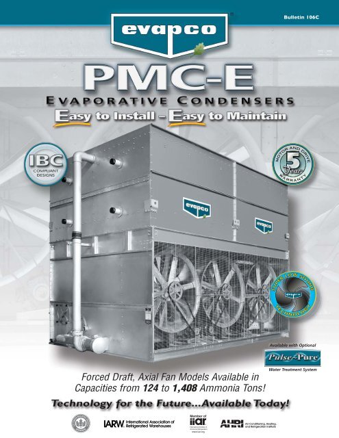
Forced Draft, Axial Fan Models Available in<br />
Capacities from 124 to 1,408 Ammonia Tons!<br />
Bulletin 106C<br />
MOTOR AND DRIVE<br />
WA R R A N T Y<br />
SOUND<br />
SOUND<br />
LOW<br />
LOW<br />
SSUPER<br />
SUPER<br />
TECHNOLOGY<br />
TECHNOLOGY<br />
Available with Optional<br />
Water Treatment System
2<br />
Since its founding in 1976, <strong>EVAPCO</strong>, Incorporated has<br />
be<strong>com</strong>e an industry leader in the engineering and<br />
manufacturing of quality heat transfer products around the<br />
world. <strong>EVAPCO</strong>’s mission is to provide first class service<br />
and quality products for the following markets:<br />
� Industrial Refrigeration<br />
� Commercial HVAC<br />
� Industrial Process<br />
� Power<br />
<strong>EVAPCO</strong>’s powerful <strong>com</strong>bination of financial strength and<br />
technical expertise has established the <strong>com</strong>pany as a<br />
recognized manufacturer of market-leading products on a<br />
worldwide basis. <strong>EVAPCO</strong> is also recognized for the superior<br />
technology of their environmentally friendly product<br />
innovations in sound reduction and water management.<br />
<strong>EVAPCO</strong> is an employee owned <strong>com</strong>pany with a strong<br />
emphasis on research & development and modern<br />
manufacturing plants. <strong>EVAPCO</strong> has earned a reputation for<br />
technological innovation and superior product quality by<br />
featuring products that are designed to offer these<br />
operating advantages:<br />
� Higher System Efficiency<br />
� Environmentally Friendly<br />
� Lower Annual Operating Costs<br />
� Reliable, Simple Operation and Maintenance<br />
With an ongoing <strong>com</strong>mitment to Research & Development<br />
programs, <strong>EVAPCO</strong> provides the most advanced products in<br />
the industry – Technology for the Future, Available Today!<br />
<strong>EVAPCO</strong> products are manufactured in 17 locations in 8<br />
countries around the world and supplied through a sales<br />
network consisting of over 170 offices.<br />
©2010 <strong>EVAPCO</strong>, Inc.<br />
<strong>PMC</strong>-E Design<br />
The industry standard for forced draft<br />
and benefits that make it Easy to<br />
NEW<br />
®<br />
ZM ZMII<br />
II<br />
MAINTENANCE<br />
MAINTENANCE<br />
ZERO<br />
ZERO<br />
PP SS RR AY AY NN OO ZZ ZZ LL EE<br />
PVC Water Distribution with ZM ® II Nozzles<br />
• Large orifice prevents clogging (no moving parts).<br />
• Redesigned nozzles for superior water distribution.<br />
• Threaded nozzles eliminate troublesome grommets.<br />
• Fixed position require zero maintenance.<br />
• Threaded end caps for ease of cleaning.<br />
• Guaranteed for life.<br />
Thermal Pak ® II Heat Transfer Technology<br />
• More surface area per plan area than<br />
<strong>com</strong>petitive designs.<br />
• Improved heat transfer efficiency due to tube<br />
geometry and orientation of tubes.<br />
• Lower refrigerant charge.<br />
• Optional TITAN stainless steel coil technology.<br />
Improved Water Distribution Piping<br />
• Horizontally mounted pumps allow for reduced<br />
basin water level.*<br />
• Simplified piping for easier basin access.<br />
• Totally enclosed pump motors assure long,<br />
trouble-free life.<br />
*Refer to engineering data for availability.<br />
NEW<br />
Optional<br />
Super Low Sound Fan<br />
(Shown in Photograph)<br />
• Extremely wide chord fan blades<br />
for sound sensitive applications.<br />
• One piece molded heavy duty<br />
construction.<br />
• 10-13 dB(A) sound reduction on<br />
fan side at 50 ft.
and Construction Features<br />
axial fan condensers. The <strong>PMC</strong>-E is equipped with owner-oriented features<br />
install...Easy to maintain...Easy on the operating budget...The Easy Choice!<br />
Sloped Pan Bottom<br />
• Pan bottom slopes to drain.<br />
• Easy to clean.<br />
• Stainless steel strainer resists corrosion.<br />
NEW<br />
MOTOR AND DRIVE<br />
WA R R A N T Y<br />
Individual Fan Drive System<br />
Water Saver Drift Eliminators<br />
• New patented design reduces drift rate to 0.001%.<br />
• Saves water and reduces water treatment cost.<br />
• Greater structural integrity vs.old style blade-type.<br />
• Recessed into casing for greater protection.<br />
U.S. Patent No. 6315804<br />
• Increased flexibility for improved capacity control.<br />
• Greater reliability through redundancy.<br />
• Easy motor replacement.<br />
• Front mounted drives for improved maintenance accessibility.<br />
Double-Brake<br />
Flange Joints<br />
• Stronger than single-brake<br />
designs by others.<br />
• Greater structural integrity.<br />
• Minimizes water leaks at<br />
field joints.<br />
Unique Field Seam<br />
• Eliminates up to 85% of fasteners.<br />
• Self guiding channels improve quality<br />
of field seam to eliminate leaks.<br />
• Easy to install.<br />
• Lower installation cost.<br />
Optional Design Features:<br />
• Man-sized Access Doors.<br />
• External Service Platforms.<br />
• Tandem Fan Drive System<br />
(Standard Fan Only).<br />
• Stainless Steel Construction.<br />
Optional Man-sized Access Door<br />
3
<strong>PMC</strong>-E Design Features<br />
4<br />
Proven Performance & Design Flexibility<br />
The new <strong>PMC</strong>-E Evaporative Condenser offers more capacity and greater<br />
system design flexibility than ever before. <strong>EVAPCO</strong>'s research and development<br />
team has invested hundreds of hours in laboratory testing to develop the next<br />
generation in Forced Draft Condenser Technology. These efforts have produced<br />
a totally new fan section design which is now <strong>com</strong>bined with the proven<br />
Thermal-Pak II ® coil technology to offer improved condenser performance.<br />
The <strong>PMC</strong>-E features more plan area options and fan horsepower options for the<br />
system design engineer. With more condenser capacity, more plan area options<br />
and greater flexibility in motor selection, the design engineer can now match the<br />
condenser performance to the specific application requirements. More equipment<br />
choices and more design flexibility mean greater value for the End-User.<br />
Thermal-Pak II ® Coil Design<br />
Lower Refrigerant Charge<br />
Only <strong>EVAPCO</strong> condensers offer the unique Thermal-Pak II ® Coil which assures greater operating<br />
efficiency in your condenser. Its unique elliptical tube design allows for closer tube spacing<br />
resulting in more surface area per plan area than traditional round tube designs. The Thermal-<br />
Pak II ® Coil design has lower resistance to air flow and permits greater water loading, making<br />
the Thermal-Pak II ® Coil the most efficient design available. And now with its new tube circuiting<br />
and orientation pattern, the Thermal-Pak II ® coil yields a lower refrigerant charge.<br />
Energy Efficient for Lowest Operating Cost<br />
Round Tube Coil by Others<br />
Lower Horsepower Options<br />
The new fan drive system of the <strong>PMC</strong>-E utilizes larger diameter vane-axial fans in a two stage arrangement to provide more<br />
efficient air flow and reduced power consumption. When <strong>com</strong>pared to the traditional centrifugal fan condenser models, the<br />
vane-axial fan design can offer up to a 50% reduction in energy consumption. And, with the new <strong>PMC</strong>-E model selections<br />
even more low horsepower options are available to obtain greater energy savings.<br />
Individual Fan Drive System<br />
Capacity Control Flexibility & Operating Redundancy<br />
The new <strong>PMC</strong>-E fan drive system provides individual motor to fan configuration as standard<br />
equipment on all models. The dedicated fan to motor arrangement ensures less “wear &<br />
tear” on the drive system versus tandem fan motor drive arrangements resulting in less<br />
maintenance. The individual motor to fan design offers greater capacity control flexibility to<br />
match the system load requirements. In addition, all Evapco condensers are equipped with<br />
an internal baffle system which extends from the pan bottom vertically through the coil<br />
bundle. This unique design allows the user to cycle fan motors independently without<br />
harmful effects of air by-pass inside the unit. The individual motor to fan design ensures<br />
maximum operating redundancy in the condenser fan system when critical operation is<br />
necessary. The <strong>PMC</strong>-E <strong>com</strong>es standard with a 5 Year motor and drive warranty.<br />
Inverter Duty Motors<br />
STANDARD!<br />
Thermal-Pak II ® Coil by <strong>EVAPCO</strong><br />
Inverter Duty motors are standard on <strong>PMC</strong>-E Condensers. Inverter Duty motors are totally enclosed, premium efficiency and inverter<br />
capable (VFD by others).<br />
Note: Variable Frequency Drive control may require other <strong>com</strong>ponent modification such as motor shaft grounding brushes, AC<br />
load reactors, low pass filters and tuned trap filters to ensure proper motor performance and service life.
Easy Field Assembly<br />
Fewer Fasteners<br />
Lower Installed Cost<br />
The <strong>PMC</strong>-E features a new field seam design which ensures easier assembly and<br />
fewer field seam leaks. The field seam incorporates new self-guiding channels to<br />
guide the coil casing section into position and set in place on the bottom fan<br />
section of the condenser. In addition, the design eliminates up to 85% of the<br />
required fasteners typically used to join the condenser sections in the field<br />
significantly reducing the contractor labor costs for installation.<br />
Improved Maintenance<br />
Fan Drive Accessibility<br />
The drive <strong>com</strong>ponents of the <strong>PMC</strong>-E are easily accessed for routine maintenance from the front of the unit. Bearing grease<br />
fittings are extended to the outside of the unit for ease of lubrication. All drive sheaves have been relocated to the front of the<br />
fan section and motors are positioned on a platform base to allow for easy belt tension adjustment.<br />
Easy Clean Sloped Basin<br />
The <strong>PMC</strong>-E basin is designed to improve maintenance access and make<br />
it easier for operating technicians to clean. The bottom of the pan is<br />
sloped to the unit drain to ensure that the basin will <strong>com</strong>pletely drain<br />
and allow sediment and debris that may collect in the basin to be easily<br />
flushed from the unit. The design helps to prevent buildup of<br />
sedimentary deposits, biological films and standing water. In addition,<br />
Evapco offers a special “man-sized” access door option to improve<br />
access to this critical area of the unit.<br />
Construction Features<br />
Unique Seam Design–Eliminate Field Leaks<br />
The new <strong>PMC</strong>-E features Evapco's unique panel construction design which<br />
includes a special butyl tape sealer with an integral sealing gasket. Each joint is<br />
then backed with a secondary caulking <strong>com</strong>pound and encased in a double-brake<br />
flange for added strength and structural integrity. This unique sealing system has<br />
been proven effective in both laboratory tests and years of field application.<br />
Superior Water Saver Drift Eliminators<br />
The <strong>PMC</strong>-E condensers incorporate a patented* highly efficient PVC drift<br />
eliminator. The eliminator removes entrained water droplets from the air stream<br />
to limit the drift rate to less than 0.001% of the recirculating water rate. With a<br />
low drift rate, <strong>PMC</strong>-E condensers save valuable water and water treatment<br />
chemicals. The eliminators feature a honey<strong>com</strong>b design which offers greater<br />
structural integrity and are recessed in the top of the casing and UV protected<br />
for longer life. They are constructed of inert polyvinyl chloride (PVC) which<br />
eliminates corrosion in this critical area of the condenser. The eliminators are<br />
assembled in sections for easy handling and removal for coil and water<br />
distribution system inspection.<br />
*U.S. Patent No. 6315804<br />
Overlay<br />
Sealant<br />
Integral<br />
Compression<br />
Shim<br />
Anti-Leak<br />
Sealer Strip<br />
5
IBC Compliance<br />
6<br />
IBC Compliance<br />
<strong>EVAPCO</strong> has been applying advanced structural technology to<br />
evaporative condensers for many years. Following seismic<br />
events in the mid 1990’s <strong>EVAPCO</strong> introduced the UB Series of<br />
induced draft cooling towers, fluid coolers and evaporative<br />
condensers. These products were designed, built and<br />
independently certified for extreme seismic and wind forces.<br />
With the advent of the International Building Code, <strong>EVAPCO</strong> is<br />
now offering a new line of <strong>PMC</strong>-E Evaporative Condensers that<br />
are IBC 2006 <strong>com</strong>pliant as standard construction.<br />
International Building Code<br />
The International Building Code (IBC) is a <strong>com</strong>prehensive set of<br />
regulations addressing the structural design and installation<br />
requirements for building systems – including HVAC and<br />
industrial refrigeration equipment. As of June 2008, all 50 states<br />
plus Washington D.C have adopted the International Building<br />
Code. Compared to previous building codes that solely<br />
examined anchorage, the earthquake provisions contained within<br />
the International Building Code address anchorage, structural<br />
integrity, and operational capability of a <strong>com</strong>ponent following a<br />
seismic event. The goal of the IBC is to minimize the loss of life<br />
and improve the capability of essential facilities to operate after a<br />
seismic event.<br />
The International Building Code (IBC) was developed to replace<br />
the BOCA National Building Code, ICBO’s Uniform Building Code<br />
and SBCCI’s Standard Building Code. The International Building<br />
Code specifies that all <strong>com</strong>ponents be designed to resist the<br />
equivalent seismic forces as the structure to which they are<br />
installed whereas previous building codes focused exclusively on<br />
the structure of the building to provide resistance against<br />
seismic forces. These <strong>com</strong>ponents include all aspects of the<br />
building architectural, electrical and mechanical systems. The<br />
failure of these <strong>com</strong>ponents during a seismic event has been a<br />
<strong>com</strong>mon occurrence in recent history. Although the structure of<br />
the building may be relatively undamaged from an earthquake,<br />
the damage to the nonstructural <strong>com</strong>ponents could be<br />
significant and result in considerable secondary damage to the<br />
building (ie. flooding, fire, structural damage).<br />
Seismic Design<br />
The IBC specifies that all installed <strong>com</strong>ponents must meet the<br />
requirements of ASCE 7-05 (American Society of Civil Engineers,<br />
Minimum Design Loads for Buildings and Other Structures).<br />
Exemptions noted in the code are for all mechanical <strong>com</strong>ponents<br />
assigned to seismic design categories A or B. ASCE 7-05<br />
explicitly states that in addition to the attachment and supports,<br />
the <strong>com</strong>ponent itself must be designed to withstand the seismic<br />
forces prescribed in the code. Simply stated, the code provisions<br />
require that evaporative cooling equipment and all other<br />
<strong>com</strong>ponents permanently installed on a structure must meet the<br />
same seismic design criteria as the building.<br />
The seismic design force, utilized for <strong>com</strong>ponent design,<br />
represents an equivalent static force that is applied to the<br />
<strong>com</strong>ponents’ center of gravity as described in the following<br />
equation:<br />
F p = [(0.4 * (a p) * (S DS) * (W p)) / (R p / I p)] * (1 + 2 * (z / h))<br />
Fp = Seismic Design Force centered at the <strong>com</strong>ponent’s center<br />
of gravity<br />
SDS = Design spectral response acceleration, short period<br />
ap = Component amplification factor<br />
Ip = Component importance factor<br />
Wp = Component operating weight<br />
Rp = Component response modification factor<br />
z = Height in structure of point of attachment of <strong>com</strong>ponent with<br />
respect to the base<br />
h = Average roof height of structure with respect to the base<br />
The minimum and maximum design force limits are specified as:<br />
Fp-min = 0.3 SDS Ip Wp Fp-max = 1.6 SDS Ip Wp A series of charts and graphs are used to determine the<br />
appropriate factors based on the location of the installation and<br />
ultimately the “importance” of the facility. A chart of the<br />
potential seismic activity in the United States is shown below.<br />
Map courtesy US Geological Survey website<br />
Highest Hazard<br />
32+<br />
24-32<br />
16-24<br />
%g 8-16<br />
4-8<br />
2-4<br />
0-2<br />
Lowest Hazard
IBC Compliance<br />
Importance Factor (Ip)<br />
A major parameter that must be determined prior to calculating<br />
the seismic design force is the <strong>com</strong>ponent importance factor<br />
(Ip). ASCE 7-05 defines the <strong>com</strong>ponent importance factor as:<br />
Importance<br />
Factor, Ip<br />
1.5<br />
Classification<br />
• Life safety <strong>com</strong>ponent required to<br />
function after seismic event.<br />
• Component containing hazardous content<br />
• Components installed at Group III<br />
(essential) facilities<br />
1.0 All other <strong>com</strong>ponents<br />
<strong>Product</strong>s such as ammonia refrigerant condensers should<br />
always be assigned an importance factor of 1.5 since they<br />
contain ammonia. The IBC identifies ammonia as hazardous<br />
content in reference of OSHA standards. According to the<br />
American Society of Civil Engineers (ASCE) Manual, 07-05<br />
edition, section 13.1.3, hazardous materials require an<br />
importance factor of 1.5.<br />
Certificate of Compliance<br />
LSTE, LPT and PMTQ Cooling Towers<br />
PMWQ, LSWE, LRWB Closed Circuit Coolers<br />
<strong>PMC</strong>-E, LSC-E and LRC Evaporative Condensers<br />
Are certified to meet or exceed the Seismic and Wind Load Provisions<br />
set forth in the applicable building codes for this project.<br />
These products have been manufactured following all<br />
applicable quality assurance programs.<br />
Applicable Building Codes:<br />
IBC 2006<br />
ASCE-7<br />
NFPA 5000<br />
Referenced Report:<br />
VMA-43387<br />
Approval Agency:<br />
VMC Seismic Consulting Group<br />
<strong>EVAPCO</strong>...Specialists in Heat Transfer <strong>Product</strong>s and Services. FD IBC COC 001<br />
Design Implementation<br />
In order to achieve this goal, an architect or civil engineer is<br />
responsible for analyzing the soil and the design of a structure<br />
to determine the factors to be used. A mechanical consulting<br />
engineer and/or design build contractor applies these factors to<br />
advise the manufacturer on the proper design for the<br />
application. <strong>EVAPCO</strong> takes this information and determines the<br />
necessary equipment to meet IBC regulations. Evapco then<br />
determines the condenser design requirements based on the<br />
IBC criteria. The standard <strong>PMC</strong>-E design is independently<br />
certified to meet the 1g IBC <strong>com</strong>pliance factors. For<br />
applications that require a more severe seismic duty, <strong>EVAPCO</strong><br />
offers an optional 5.12g construction design. This process<br />
ensures that the mechanical equipment and its <strong>com</strong>ponents are<br />
seismically <strong>com</strong>pliant per the provisions of the International<br />
Building Code.<br />
Independent Certification<br />
As required by the International Building Code, <strong>EVAPCO</strong><br />
supplies a certificate of <strong>com</strong>pliance as part of its submittal<br />
documents. The certificate of <strong>com</strong>pliance should demonstrate<br />
that the equipment/unit has been independently tested and<br />
analyzed in accordance with the IBC program. Evapco has<br />
worked closely with Vibrations Mountings and Controls Group<br />
(VMC) to <strong>com</strong>plete the independent equipment testing and<br />
analysis. A sample of the certificate of <strong>com</strong>pliance and unit<br />
label is presented below:<br />
Seismic and Wind Load Certification<br />
LSTE, LPT and PMTQ Cooling Towers<br />
PMWQ, LSWE and LRWB Closed Circuit Coolers<br />
<strong>PMC</strong>-E, LSC-E and LRC Evaporative Condensers<br />
IBC<br />
Serial<br />
Number:<br />
43387<br />
Units Designed and Manufactured to Meet the<br />
Seismic & Wind Load Requirements of:<br />
IBC 2006 ASCE-7 NFPA 5000<br />
Independent Certification By:<br />
15-248PA<br />
7
<strong>PMC</strong>-E Selection Procedure<br />
8<br />
Selection Procedure<br />
Two methods of selection are presented, the first is based on the<br />
total heat of rejection as described immediately below. The second<br />
and more simple method is based on evaporator tons. The<br />
evaporator ton method is only applicable to systems with open type<br />
reciprocating <strong>com</strong>pressors.<br />
The heat of rejection method is applicable to all but centrifugal<br />
<strong>com</strong>pressor applications and is normally used for selecting<br />
evaporative condensers for use with hermetic <strong>com</strong>pressors and screw<br />
<strong>com</strong>pressors. It can also be used for standard open type reciprocating<br />
<strong>com</strong>pressors as an alternate to the evaporator ton method.<br />
The evaporator ton method is based on the estimated heat of<br />
<strong>com</strong>pression. The heat of rejection method of selection is more<br />
accurate and should be used whenever possible.<br />
Refer to the factory for selections on systems with centrifugal<br />
<strong>com</strong>pressors.<br />
Principle of Operation<br />
The refrigerant gas is discharged from the <strong>com</strong>pressor into the inlet<br />
connection of the evaporative condenser. Water from the<br />
condenser’s sump is continuously flooded over the condenser coil,<br />
while ambient air is simultaneously forced into the unit. As the<br />
ambient air moves up through the coil section, a portion of the<br />
spray water is evaporated into the air stream.<br />
The evaporative process cools the spray water, which in turn cools<br />
the tubes containing the refrigerant gas. The cool tube walls cause<br />
the refrigerant gas to give up heat and condense into a liquid. The<br />
condensed liquid flows out of the coil’s sloping tubes to the high<br />
pressure liquid receiver for return to the system.<br />
The hot, saturated air is driven through the drift eliminators, where<br />
any entrained water droplets are removed. The condenser’s fan then<br />
discharges this air stream out of the top of the unit at a high<br />
velocity, where it can dissipate harmlessly into the atmosphere. The<br />
water which was not evaporated falls into the sump and is<br />
recirculated by the spray pump to the water distribution system<br />
above the condensing coil section.<br />
Superheated<br />
Refrigerant<br />
Gas In<br />
Condensed<br />
Refrigerant<br />
Liquid Out<br />
Cool Dry<br />
Entering Air<br />
Hot Saturated<br />
Discharge Air<br />
Principle of Operation<br />
Heat of Rejection Method<br />
In the heat of rejection method, a factor for the specified operating<br />
conditions (condensing temperature and wet bulb) is obtained from<br />
Table 1 or 2 and multiplied times the heat of rejection.<br />
The resultant figure is used to select a unit from Table 3. Unit<br />
capacities are given in Table 3 in thousands of BTU/Hr or MBH.<br />
If the heat of rejection is not known, it can be determined by one of<br />
the following formulas:<br />
Open Compressors:<br />
Heat of Rejection = Evaporator Load (BTU/Hr) + Compressor<br />
BHP x 2545<br />
Hermetic Compressors:<br />
Heat of Rejection = Evaporator Load (BTU/Hr) + K.W.<br />
Compressor Input x 3415<br />
EXAMPLE<br />
Given: 450 ton load, ammonia refrigerant 96.3° condensing<br />
temperature, 78° W.B. temperature and 500 <strong>com</strong>pressor BHP.<br />
Selection: Heat of Rejection<br />
450 tons x 12000 = 5,400,000 BTU/Hr<br />
500 BHP x 2545 = 1,272,500 BTU/Hr<br />
Total 6,672,500 BTU/Hr<br />
From Table 2 the capacity factor for 96.3° condensing and<br />
78° W.B. = 1.37 6,672,500 x 1.37 = 9,141,325 BTU/Hr or<br />
9142 MBH. Therefore, select a model <strong>PMC</strong>-631E-1g.<br />
Note: For screw <strong>com</strong>pressor selections employing water cooled oil<br />
cooling, select a condenser for the total MBH as in the example.<br />
The condenser can then function in one of two ways:<br />
(1) Recirculating water from the water sump can be used<br />
directly in the oil cooler. A separate pump should be employed<br />
and the return water should be directed into the water sump at<br />
the opposite end from the pump suction.<br />
(2) The condenser coil can be circuited so that water or a<br />
glycol-water mixture for the oil cooler can be cooled in a<br />
separate section of the coil. Specify load and water flow<br />
required.<br />
For refrigerant injection cooled screw <strong>com</strong>pressors, select the<br />
condenser in the same manner as shown in the example.<br />
If the oil cooler is supplied by water from a separate source, then<br />
the oil cooling load should be deducted from the heat of rejection<br />
before making the selection.
Table 1 - HCFC-22 and HFC-134a Heat Rejection Factors<br />
Condensing<br />
Pres. psig<br />
HCFC- HFC-<br />
22 134a<br />
Cond.<br />
Temp.<br />
°F<br />
50 55 60 62 64 66 68<br />
Wet Bulb Temperature, (°F)<br />
70 72 74 75 76 77 78 80 82 84 86<br />
156 95 85 1.10 1.22 1.39 1.50 1.61 1.75 1.93 2.13 2.42 2.78 3.02 3.29 3.64 4.00 - - - -<br />
168 104 90 .93 1.02 1.14 1.21 1.28 1.36 1.45 1.57 1.71 1.89 2.00 2.12 2.25 2.38 2.85 3.50 - -<br />
182 114 95 .80 .87 .95 1.00 1.05 1.10 1.15 1.22 1.31 1.40 1.45 1.50 1.56 1.64 1.82 2.07 2.37 2.77<br />
196 124 100 .71 .76 .82 .85 .88 .91 .94 .98 1.03 1.09 1.12 1.15 1.20 1.24 1.34 1.46 1.63 1.82<br />
211 135 105 .63 .66 .70 .72 .75 .77 .80 .83 .87 .91 .93 .95 .97 1.00 1.06 1.13 1.23 1.35<br />
226 146 110 .56 .59 .62 .64 .65 .67 .69 .71 .74 .77 .78 .80 .82 .84 .88 .93 .98 1.04<br />
Note: Consult factory for selections using other refrigerants.<br />
Table 2 - Ammonia (R-717) Heat Rejection Factors<br />
Condensing<br />
Pres.<br />
Cond.<br />
Temp.<br />
Wet Bulb Temperature, (°F)<br />
psig °F<br />
50 55 60 62 64 66 68 70 72 74 75 76 77 78 80 82 84 86<br />
152 85 .98 1.09 1.24 1.34 1.44 1.56 1.72 1.90 2.16 2.48 2.70 2.94 3.25 3.57 - - - -<br />
166 90 .83 .91 1.02 1.08 1.14 1.21 1.29 1.40 1.53 1.69 1.79 1.89 2.01 2.12 2.54 3.12 - -<br />
181 95 .71 .78 .85 .89 .94 .98 1.03 1.09 1.17 1.25 1.29 1.34 1.39 1.47 1.63 1.85 2.12 2.47<br />
185 96.3 .69 .75 .82 .86 .90 .94 .98 1.03 1.10 1.18 1.22 1.26 1.31 1.37 1.51 1.71 1.94 2.25<br />
197 100 .63 .68 .73 .76 .79 .81 .84 .87 .92 .97 1.00 1.03 1.07 1.11 1.20 1.30 1.46 1.63<br />
214 105 .56 .59 .62 .64 .67 .69 .71 .74 .78 .81 .83 .85 .87 .89 .95 1.01 1.10 1.21<br />
232 110 .50 .53 .55 .57 .58 .60 .62 .63 .66 .69 .70 .71 .73 .75 .79 .83 .87 .93<br />
Table 3 - Unit Heat Rejection<br />
Model MBH Base<br />
<strong>PMC</strong>-175E-1g 2572.5<br />
<strong>PMC</strong>-190E-1g 2793.0<br />
<strong>PMC</strong>-210E-1g 3087.0<br />
<strong>PMC</strong>-220E-1g 3234.0<br />
<strong>PMC</strong>-235E-1g 3454.5<br />
<strong>PMC</strong>-240E-1g 3528.0<br />
<strong>PMC</strong>-250E-1g 3675.0<br />
<strong>PMC</strong>-275E-1g 4042.5<br />
<strong>PMC</strong>-295E-1g 4336.5<br />
<strong>PMC</strong>-325E-1g 4777.5<br />
<strong>PMC</strong>-332E-1g 4880.4<br />
<strong>PMC</strong>-335E-1g 4924.5<br />
<strong>PMC</strong>-360E-1g 5292.0<br />
<strong>PMC</strong>-369E-1g 5424.3<br />
<strong>PMC</strong>-375E-1g 5512.5<br />
<strong>PMC</strong>-386E-1g 5674.2<br />
<strong>PMC</strong>-397E-1g 5835.9<br />
<strong>PMC</strong>-400E-1g 5880.0<br />
<strong>PMC</strong>-420E-1g 6174.0<br />
<strong>PMC</strong>-426E-1g 6262.2<br />
Model MBH Base<br />
<strong>PMC</strong>-428E-1g 6291.6<br />
<strong>PMC</strong>-431E-1g 6335.7<br />
<strong>PMC</strong>-450E-1g 6615.0<br />
<strong>PMC</strong>-457E-1g 6717.9<br />
<strong>PMC</strong>-464E-1g 6820.8<br />
<strong>PMC</strong>-481E-1g 7070.7<br />
<strong>PMC</strong>-488E-1g 7173.6<br />
<strong>PMC</strong>-492E-1g 7232.4<br />
<strong>PMC</strong>-495E-1g 7276.5<br />
<strong>PMC</strong>-503E-1g 7394.1<br />
<strong>PMC</strong>-515E-1g 7570.5<br />
<strong>PMC</strong>-519E-1g 7629.3<br />
<strong>PMC</strong>-536E-1g 7879.2<br />
<strong>PMC</strong>-558E-1g 8202.6<br />
<strong>PMC</strong>-559E-1g 8217.3<br />
<strong>PMC</strong>-564E-1g 8290.8<br />
<strong>PMC</strong>-591E-1g 8687.7<br />
<strong>PMC</strong>-596E-1g 8761.2<br />
<strong>PMC</strong>-601E-1g 8834.7<br />
<strong>PMC</strong>-605E-1g 8893.5<br />
Model MBH Base<br />
<strong>PMC</strong>-631E-1g 9275.7<br />
<strong>PMC</strong>-634E-1g 9319.8<br />
<strong>PMC</strong>-636E-1g 9349.2<br />
<strong>PMC</strong>-645E-1g 9481.5<br />
<strong>PMC</strong>-679E-1g 9981.3<br />
<strong>PMC</strong>-688E-1g 10113.6<br />
<strong>PMC</strong>-690E-1g 10143.0<br />
<strong>PMC</strong>-691E-1g 10157.7<br />
<strong>PMC</strong>-719E-1g 10569.3<br />
<strong>PMC</strong>-723E-1g 10628.1<br />
<strong>PMC</strong>-731E-1g 10745.7<br />
<strong>PMC</strong>-737E-1g 10833.9<br />
<strong>PMC</strong>-772E-1g 11348.4<br />
<strong>PMC</strong>-774E-1g 11377.8<br />
<strong>PMC</strong>-778E-1g 11436.6<br />
<strong>PMC</strong>-800E-1g 11760.0<br />
<strong>PMC</strong>-801E-1g 11774.7<br />
<strong>PMC</strong>-811E-1g 11921.7<br />
<strong>PMC</strong>-831E-1g 12215.7<br />
<strong>PMC</strong>-840E-1g 12348.0<br />
Model MBH Base<br />
<strong>PMC</strong>-852E-1g 12524.4<br />
<strong>PMC</strong>-853E-1g 12539.1<br />
<strong>PMC</strong>-856E-1g 12583.2<br />
<strong>PMC</strong>-863E-1g 12686.1<br />
<strong>PMC</strong>-888E-1g 13053.6<br />
<strong>PMC</strong>-889E-1g 13068.3<br />
<strong>PMC</strong>-894E-1g 13141.8<br />
<strong>PMC</strong>-895E-1g 13156.5<br />
<strong>PMC</strong>-900E-1g 13230.0<br />
<strong>PMC</strong>-929E-1g 13656.3<br />
<strong>PMC</strong>-939E-1g 13803.3<br />
<strong>PMC</strong>-940E-1g 13818.0<br />
<strong>PMC</strong>-949E-1g 13950.3<br />
<strong>PMC</strong>-956E-1g 14053.2<br />
<strong>PMC</strong>-962E-1g 14141.4<br />
<strong>PMC</strong>-974E-1g 14317.8<br />
<strong>PMC</strong>-976E-1g 14347.2<br />
<strong>PMC</strong>-983E-1g 14450.1<br />
<strong>PMC</strong>-989E-1g 14538.3<br />
<strong>PMC</strong>-992E-1g 14582.4<br />
Model MBH Base<br />
<strong>PMC</strong>-1006E-1g 14788.2<br />
<strong>PMC</strong>-1024E-1g 15052.8<br />
<strong>PMC</strong>-1038E-1g 15258.6<br />
<strong>PMC</strong>-1071E-1g 15743.7<br />
<strong>PMC</strong>-1073E-1g 15773.1<br />
<strong>PMC</strong>-1088E-1g 15993.6<br />
<strong>PMC</strong>-1116E-1g 16405.2<br />
<strong>PMC</strong>-1117E-1g 16419.9<br />
<strong>PMC</strong>-1125E-1g 16537.5<br />
<strong>PMC</strong>-1127E-1g 16566.9<br />
<strong>PMC</strong>-1180E-1g 17346.0<br />
<strong>PMC</strong>-1182E-1g 17375.4<br />
<strong>PMC</strong>-1189E-1g 17478.3<br />
<strong>PMC</strong>-1201E-1g 17654.7<br />
<strong>PMC</strong>-1203E-1g 17684.1<br />
<strong>PMC</strong>-1211E-1g 17801.7<br />
<strong>PMC</strong>-1258E-1g 18492.6<br />
<strong>PMC</strong>-1261E-1g 18536.7<br />
<strong>PMC</strong>-1269E-1g 18654.3<br />
<strong>PMC</strong>-1275E-1g 18742.5<br />
Model MBH Base<br />
<strong>PMC</strong>-1290E-1g 18963.0<br />
<strong>PMC</strong>-1358E-1g 19962.6<br />
<strong>PMC</strong>-1376E-1g 20227.2<br />
<strong>PMC</strong>-1382E-1g 20315.4<br />
<strong>PMC</strong>-1438E-1g 21138.6<br />
<strong>PMC</strong>-1446E-1g 21256.2<br />
<strong>PMC</strong>-1473E-1g 21653.1<br />
<strong>PMC</strong>-1549E-1g 22770.3<br />
<strong>PMC</strong>-1556E-1g 22873.2<br />
<strong>PMC</strong>-1599E-1g 23505.3<br />
<strong>PMC</strong>-1625E-1g 23887.5<br />
<strong>PMC</strong>-1705E-1g 25063.5<br />
<strong>PMC</strong>-1712E-1g 25166.4<br />
<strong>PMC</strong>-1776E-1g 26107.2<br />
<strong>PMC</strong>-1788E-1g 26283.6<br />
<strong>PMC</strong>-1877E-1g 27591.9<br />
<strong>PMC</strong>-1879E-1g 27621.3<br />
<strong>PMC</strong>-1985E-1g 29179.5<br />
9
<strong>PMC</strong>-E Selection Procedure<br />
10<br />
Evaporator Ton Method<br />
In the evaporator ton method, factors for the specified<br />
operating conditions (suction temperature, condensing<br />
temperature and wet bulb) are obtained from either Table 5 or<br />
6 and multiplied times the heat load in tons. The resultant<br />
figure is used to select a unit from Table 4. The condenser<br />
model in Table 4 is equal to the unit capacity in evaporator<br />
tons for HCFC-22 or HFC-134a conditions of 105°F<br />
condensing, 40°F suction and 78° wet bulb.<br />
Table 4 - Unit Sizes<br />
Model Capacity<br />
<strong>PMC</strong>-175E-1g 175<br />
<strong>PMC</strong>-190E-1g 190<br />
<strong>PMC</strong>-210E-1g 210<br />
<strong>PMC</strong>-220E-1g 220<br />
<strong>PMC</strong>-235E-1g 235<br />
<strong>PMC</strong>-240E-1g 240<br />
<strong>PMC</strong>-250E-1g 250<br />
<strong>PMC</strong>-275E-1g 275<br />
<strong>PMC</strong>-295E-1g 295<br />
<strong>PMC</strong>-325E-1g 325<br />
<strong>PMC</strong>-332E-1g 332<br />
<strong>PMC</strong>-335E-1g 335<br />
<strong>PMC</strong>-360E-1g 360<br />
<strong>PMC</strong>-369E-1g 369<br />
<strong>PMC</strong>-375-E-1g 375<br />
<strong>PMC</strong>-386E-1g 386<br />
<strong>PMC</strong>-397E-1g 397<br />
<strong>PMC</strong>-400E-1g 400<br />
<strong>PMC</strong>-420E-1g 420<br />
<strong>PMC</strong>-426E-1g 426<br />
<strong>PMC</strong>-428E-1g 428<br />
<strong>PMC</strong>-431E-1g 431<br />
<strong>PMC</strong>-450E-1g 450<br />
<strong>PMC</strong>-457E-1g 457<br />
<strong>PMC</strong>-464E-1g 464<br />
<strong>PMC</strong>-481E-1g 481<br />
<strong>PMC</strong>-488E-1g 488<br />
<strong>PMC</strong>-492E-1g 492<br />
<strong>PMC</strong>-495E-1g 495<br />
<strong>PMC</strong>-503E-1g 503<br />
<strong>PMC</strong>-515E-1g 515<br />
<strong>PMC</strong>-519E-1g 519<br />
<strong>PMC</strong>-536E-1g 536<br />
<strong>PMC</strong>-558E-1g 558<br />
<strong>PMC</strong>-559E-1g 559<br />
<strong>PMC</strong>-564E-1g 564<br />
<strong>PMC</strong>-591E-1g 591<br />
<strong>PMC</strong>-596E-1g 596<br />
<strong>PMC</strong>-601E-1g 601<br />
<strong>PMC</strong>-605E-1g 605<br />
<strong>PMC</strong>-631E-1g 631<br />
<strong>PMC</strong>-634E-1g 634<br />
<strong>PMC</strong>-636E-1g 636<br />
<strong>PMC</strong>-645E-1g 645<br />
<strong>PMC</strong>-679E-1g 679<br />
<strong>PMC</strong>-688E-1g 688<br />
<strong>PMC</strong>-690E-1g 690<br />
<strong>PMC</strong>-691E-1g 691<br />
<strong>PMC</strong>-E Models<br />
<strong>PMC</strong>-719E-1g 719<br />
<strong>PMC</strong>-723E-1g 723<br />
<strong>PMC</strong>-731E-1g 731<br />
<strong>PMC</strong>-737E-1g 737<br />
<strong>PMC</strong>-772E-1g 772<br />
<strong>PMC</strong>-774E-1g 774<br />
<strong>PMC</strong>-778E-1g 778<br />
<strong>PMC</strong>-800E-1g 800<br />
<strong>PMC</strong>-801E-1g 801<br />
<strong>PMC</strong>-811E-1g 811<br />
<strong>PMC</strong>-831E-1g 831<br />
<strong>PMC</strong>-840E-1g 840<br />
<strong>PMC</strong>-852E-1g 852<br />
<strong>PMC</strong>-853E-1g 853<br />
<strong>PMC</strong>-856E-1g 856<br />
<strong>PMC</strong>-863E-1g 863<br />
<strong>PMC</strong>-888E-1g 888<br />
<strong>PMC</strong>-889E-1g 889<br />
<strong>PMC</strong>-894E-1g 894<br />
<strong>PMC</strong>-895E-1g 895<br />
<strong>PMC</strong>-900E-1g 900<br />
<strong>PMC</strong>-929E-1g 929<br />
<strong>PMC</strong>-939E-1g 939<br />
<strong>PMC</strong>-940E-1g 940<br />
EXAMPLE<br />
Given: 300 ton evaporator load, R-717, condensing at 95° F,<br />
with +10° F suction and 76° F wet bulb temperatures.<br />
Selection: The capacity factor from Table 6 for the given<br />
condensing and wet bulb conditions is 1.38, and the capacity<br />
factor for the suction temperature of +10° F is 1.03, so the<br />
corrected capacity required may be determined as:<br />
300 X 1.38 X 1.03 = 426 corrected tons. Therefore, select a<br />
model <strong>PMC</strong>-428E-1g, <strong>PMC</strong>-431E-1g or <strong>PMC</strong>-450E-1g<br />
depending on unit type desired, and any layout or horsepower<br />
considerations.<br />
Model Capacity Model Capacity Model Capacity Model Capacity<br />
<strong>PMC</strong>-949E-1g 949<br />
<strong>PMC</strong>-956E-1g 956<br />
<strong>PMC</strong>-962E-1g 962<br />
<strong>PMC</strong>-974E-1g 974<br />
<strong>PMC</strong>-976E-1g 976<br />
<strong>PMC</strong>-983E-1g 983<br />
<strong>PMC</strong>-989E-1g 989<br />
<strong>PMC</strong>-992E-1g 992<br />
<strong>PMC</strong>-1006E-1g 1006<br />
<strong>PMC</strong>-1024E-1g 1024<br />
<strong>PMC</strong>-1038E-1g 1038<br />
<strong>PMC</strong>-1071E-1g 1071<br />
<strong>PMC</strong>-1073E-1g 1073<br />
<strong>PMC</strong>-1088E-1g 1088<br />
<strong>PMC</strong>-1116E-1g 1116<br />
<strong>PMC</strong>-1117E-1g 1117<br />
<strong>PMC</strong>-1125E-1g 1125<br />
<strong>PMC</strong>-1127E-1g 1127<br />
<strong>PMC</strong>-1180E-1g 1180<br />
<strong>PMC</strong>-1182E-1g 1182<br />
<strong>PMC</strong>-1189E-1g 1189<br />
<strong>PMC</strong>-1201E-1g 1201<br />
<strong>PMC</strong>-1203E-1g 1203<br />
<strong>PMC</strong>-1211E-1g 1211<br />
<strong>PMC</strong>-1258E-1g 1258<br />
<strong>PMC</strong>-1261E-1g 1261<br />
<strong>PMC</strong>-1269E-1g 1269<br />
<strong>PMC</strong>-1275E-1g 1275<br />
<strong>PMC</strong>-1290E-1g 1290<br />
<strong>PMC</strong>-1358E-1g 1358<br />
<strong>PMC</strong>-1376E-1g 1376<br />
<strong>PMC</strong>-1382E-1g 1382<br />
<strong>PMC</strong>-1438E-1g 1438<br />
<strong>PMC</strong>-1446E-1g 1446<br />
<strong>PMC</strong>-1473E-1g 1473<br />
<strong>PMC</strong>-1549E-1g 1549<br />
<strong>PMC</strong>-1556E-1g 1556<br />
<strong>PMC</strong>-1599E-1g 1599<br />
<strong>PMC</strong>-1625E-1g 1625<br />
<strong>PMC</strong>-1705E-1g 1705<br />
<strong>PMC</strong>-1712E-1g 1712<br />
<strong>PMC</strong>-1776E-1g 1776<br />
<strong>PMC</strong>-1788E-1g 1788<br />
<strong>PMC</strong>-1877E-1g 1877<br />
<strong>PMC</strong>-1879E-1g 1879<br />
<strong>PMC</strong>-1985E-1g 1985
Table 5 - HCFC-22 and HFC-134a Capacity Factors<br />
Condensing<br />
Pres. psig<br />
HCFC-<br />
22<br />
HFC-<br />
134a<br />
Cond.<br />
Temp.<br />
°F<br />
Table 6 - Ammonia (R-717) Capacity Factors<br />
Condensing Cond.<br />
Pres. Temp.<br />
psig °F<br />
50 55 60 62 64 66 68 70 72 74 75 76 77 78 80 82 84 86<br />
156 95 85 1.05 1.16 1.32 1.43 1.53 1.66 1.83 2.02 2.30 2.64 2.87 3.13 3.46 3.80 - - - -<br />
168 104 90 .90 .98 1.10 1.17 1.24 1.31 1.40 1.52 1.65 1.82 1.93 2.05 2.17 2.30 2.75 3.38 - -<br />
182 114 95 .78 .85 .93 .98 1.02 1.07 1.12 1.19 1.28 1.37 1.42 1.46 1.52 1.60 1.78 2.02 2.31 2.70<br />
196 124 100 .70 .75 .81 .84 .87 .90 .93 .97 1.02 1.08 1.11 1.14 1.19 1.23 1.33 1.44 1.61 1.80<br />
211 135 105 .63 .66 .70 .72 .75 .77 .80 .83 .87 .91 .93 .95 .97 1.00 1.06 1.13 1.23 1.35<br />
226 146 110 .57 .60 .63 .65 .66 .68 .70 .72 .75 .78 .79 .81 .83 .85 .89 .94 .99 1.05<br />
Suction Temp. °F -20° -10° -0° +10° +20° +30° +40° +50°<br />
Suction Press. HCFC-22 10.1 16.5 24.0 32.8 43.0 54.9 68.5 84.0<br />
(psig)<br />
HFC-134a -1.8 1.9 6.5 11.9 18.4 26.1 35.0 45.4<br />
Capacity Factor 1.22 1.17 1.13 1.09 1.06 1.03 1.00 0.97<br />
50 55 60 62 64 66 68 70 72 74 75 76 77 78 80 82 84 86<br />
152 85 .99 1.09 1.25 1.34 1.44 1.57 1.73 1.91 2.17 2.49 2.71 2.95 3.26 3.59 - - - -<br />
166 90 .84 .93 1.03 1.10 1.16 1.23 1.32 1.42 1.55 1.71 1.81 1.92 2.04 2.16 2.59 3.17 - -<br />
181 95 .74 .80 .87 .92 .97 1.01 1.06 1.12 1.21 1.29 1.33 1.38 1.44 1.51 1.68 1.91 2.18 2.55<br />
185 96.3 .72 .78 .85 .89 .93 .97 1.01 1.07 1.14 1.22 1.26 1.30 1.35 1.41 1.56 1.76 2.01 2.33<br />
197 100 .66 .71 .76 .79 .82 .85 .87 .91 .96 1.01 1.04 1.07 1.12 1.15 1.25 1.36 1.52 1.69<br />
214 105 .59 .62 .66 .68 .71 .73 .75 .78 .82 .86 .88 .90 .91 .94 1.00 1.07 1.16 1.27<br />
232 110 .53 .56 .59 .61 .62 .64 .66 .68 .71 .73 .74 .76 .78 .80 .84 .89 .93 .99<br />
Note: Consult factory for selections using other refrigerants.<br />
Wet Bulb Temperature, (°F)<br />
Wet Bulb Temperature, (°F)<br />
Suction Temp. °F -30° -20° -10° 0° +10° +20° +30° +40°<br />
Suction Press. (psig) -1.6 3.6 9.0 15.7 23.8 33.5 45.0 58.6<br />
Capacity Factor 1.18 1.14 1.10 1.07 1.03 1.00 0.97 0.95<br />
11
Engineering & Dimensions Data<br />
<strong>PMC</strong>-175E-1g to 375E-1g<br />
U<br />
Table 7 Engineering Data<br />
* Tons at standard conditions: 96.3°F condensing, 20°F suction and 78°F W.B.<br />
** Gallons shown is water in suspension in unit and piping. Allow for additional water in bottom of remote sump to cover pump suction and strainer during operation.<br />
(12” would normally be sufficient.)<br />
† Heaviest section is the upper coil section. When 5.12 seismic design is required consult the factory for specific weights.<br />
*** Refrigerant charge is shown for R-717. Multiply by 1.93 for R-22 and 1.98 for R-134a.<br />
Dimensions are subject to change. Do not use for pre-fabrication.<br />
12<br />
30-3/8"<br />
4 B.F.W. REFRIG. IN<br />
4 B.F.W. REFRIG. OUT<br />
(2)ACCESS<br />
DOOR<br />
74-1/2”<br />
2 M.P.T.<br />
DRAIN<br />
1 M.P.T.<br />
MAKE-UP 2 F.P.T.<br />
6’ 4”<br />
OVERFLOW<br />
A<br />
77-5/8”<br />
H<br />
<strong>PMC</strong>-175E-1g to 240E-1g <strong>PMC</strong>-250E-1g to 375E-1g<br />
12-1/2" 11' 11-5/8"<br />
14"<br />
18' 1/8"<br />
Refrigerant<br />
R-717 Operating Coil<br />
Model<br />
No.<br />
Capacity<br />
Tons* HP CFM Shipping<br />
Heaviest<br />
Section† Operating<br />
Charge<br />
lbs.***<br />
Volume<br />
ft<br />
Gallons Conn. Operating Height Upper Coil<br />
3 Fans Weights (lbs)†<br />
Spray Pump Remote Sump<br />
Dimensions (in.)<br />
HP GPM Req’d** Size Weight H U A<br />
<strong>PMC</strong>-175E-1g 124 (2)5 31,300 8,090 5,220 10,410 165 22 2 345 200 8 9,360 130-3/8 57-3/8 30-3/4<br />
<strong>PMC</strong>-190E-1g 135 (2)5 34,000 8,090 5,220 10,410 165 22 2 345 200 8 9,360 130-3/8 57-3/8 30-3/4<br />
<strong>PMC</strong>-210E-1g 149 (2)5 33,500 9,050 6,180 11,400 200 28 2 345 200 8 10,350 138-7/8 65-7/8 39-1/4<br />
<strong>PMC</strong>-220E-1g 156 (2)5 33,000 10,050 7,180 12,440 240 33 2 345 200 8 11,390 147-3/8 74-3/8 47-3/4<br />
<strong>PMC</strong>-235E-1g 167 (2)7.5 36,600 9,150 6,180 11,500 200 28 2 345 200 8 10,450 138-7/8 65-7/8 39-1/4<br />
<strong>PMC</strong>-240E-1g 170 (2)7.5 35,500 10,150 7,180 12,540 240 33 2 345 200 8 11,490 147-3/8 74-3/8 47-3/4<br />
<strong>PMC</strong>-250E-1g 177 (3)5 54,000 10,570 6,210 13,990 185 25 3 515 260 10 12,040 121-7/8 48-7/8 22-1/4<br />
<strong>PMC</strong>-275E-1g 195 (3)5 48,500 12,080 7,720 15,560 240 33 3 515 260 10 13,600 130-3/8 57-3/8 30-3/4<br />
<strong>PMC</strong>-295E-1g 209 (3)5 51,900 12,080 7,720 15,560 240 33 3 515 260 10 13,600 130-3/8 57-3/8 30-3/4<br />
<strong>PMC</strong>-325E-1g 230 (3)5 50,900 13,530 9,170 17,070 300 41 3 515 260 10 15,110 138-7/8 65-7/8 39-1/4<br />
<strong>PMC</strong>-335E-1g 238 (3)5 50,300 15,030 10,670 18,630 360 49 3 515 260 10 16,670 147-3/8 74-3/8 47-3/4<br />
<strong>PMC</strong>-360E-1g 255 (3)7.5 57,000 13,690 9,170 17,230 300 41 3 515 260 10 15,270 138-7/8 65-7/8 39-1/4<br />
<strong>PMC</strong>-375E-1g 266 (3)7.5 56,300 15,190 10,670 18,790 360 49 3 515 260 10 16,830 147-3/8 74-3/8 47-3/4
Engineering & Dimensions Data<br />
<strong>PMC</strong>-332E-1g to 778E-1g<br />
30-3/8”<br />
U<br />
3 M.P.T.<br />
DRAIN<br />
2 M.P.T.<br />
MAKE-UP<br />
(2)ACCESS<br />
DOOR<br />
57”<br />
(2)4 B.F.W. REFRIG. IN<br />
(2)4 B.F.W. REFRIG. OUT<br />
9’ 9-3/4”<br />
3 F.P.T.<br />
OVERFLOW<br />
Table 8 Engineering Data<br />
A<br />
119”<br />
103-1/4”<br />
H<br />
<strong>PMC</strong>-332E-1g<br />
to<br />
519E-1g<br />
<strong>PMC</strong>-503E-1g to 778E-1g<br />
18" 11' 11-3/4"<br />
20-5/8”<br />
18’ 1/8”<br />
Refrigerant<br />
R-717 Operating Coil<br />
Model<br />
No.<br />
Capacity<br />
Tons* HP CFM Shipping<br />
Heaviest<br />
Section† Operating<br />
Charge<br />
lbs.***<br />
Volume<br />
ft<br />
Gallons Conn. Operating Height Upper Coil<br />
3 Fans Weights (lbs)†<br />
Spray Pump Remote Sump<br />
Dimensions (in.)<br />
HP GPM Req’d** Size Weight H U A<br />
<strong>PMC</strong>-332E-1g 235 (2)5 61,000 12,870 8,590 16,950 250 34 5 685 500 10 16,270 163-3/8 61 22-1/4<br />
<strong>PMC</strong>-369E-1g 262 (2)7.5 70,000 12,970 8,590 17,050 250 34 5 685 500 10 16,370 163-3/8 61 22-1/4<br />
<strong>PMC</strong>-386E-1g 274 (2)5 59,200 16,700 12,420 20,940 405 56 5 685 500 10 20,260 180-3/8 78 39-1/4<br />
<strong>PMC</strong>-397E-1g 282 (2)10 77,200 13,000 8,590 17,080 250 34 5 685 500 10 16,400 163-3/8 61 22-1/4<br />
<strong>PMC</strong>-400E-1g 284 (2)7.5 69,000 14,940 10,560 19,100 325 44 5 685 500 10 18,420 171-7/8 69-1/2 30-3/4<br />
<strong>PMC</strong>-426E-1g 302 (2)7.5 67,900 16,800 12,420 21,040 405 56 5 685 500 10 20,360 180-3/8 78 39-1/4<br />
<strong>PMC</strong>-428E-1g 304 (2)15 88,700 113,260 8,590 17,340 250 34 5 685 500 10 16,660 163-3/8 61 22-1/4<br />
<strong>PMC</strong>-431E-1g 306 (2)10 76,000 14,970 10,560 19,130 325 44 5 685 500 10 18,450 171-7/8 69-1/2 30-3/4<br />
<strong>PMC</strong>-457E-1g 324 (2)10 74,900 16,830 12,420 21,070 405 56 5 685 500 10 20,390 180-3/8 78 39-1/4<br />
<strong>PMC</strong>-464E-1g 329 (2)15 87,400 15,230 10,560 19,390 325 44 5 685 500 10 18,710 171-7/8 69-1/2 30-3/4<br />
<strong>PMC</strong>-481E-1g 341 (2)10 73,800 18,780 14,370 23,090 480 66 5 685 500 10 22,410 188-7/8 86-1/2 47-3/4<br />
<strong>PMC</strong>-492E-1g 349 (2)15 86,100 17,090 12,420 21,330 405 56 5 685 500 10 20,650 180-3/8 78 39-1/4<br />
<strong>PMC</strong>-519E-1g 368 (2)15 84,800 19,040 14,370 23,350 480 66 5 685 500 10 22,670 188-7/8 86-1/2 47-3/4<br />
<strong>PMC</strong>-503E-1g 357 (3)5 91,800 19,590 12,580 25,910 365 50 7.5 1030 620 12 23,710 163-3/8 61 22-1/4<br />
<strong>PMC</strong>-558E-1g 396 (3)7.5 105,300 19,750 12,580 26,070 365 50 7.5 1030 620 12 23,870 163-3/8 61 22-1/4<br />
<strong>PMC</strong>-596E-1g 423 (3)10 116,100 19,800 12,580 26,120 365 50 7.5 1030 620 12 23,920 163-3/8 61 22-1/4<br />
<strong>PMC</strong>-605E-1g 429 (3)7.5 103,800 22,680 15,510 29,120 485 66 7.5 1030 620 12 26,920 171-7/8 69-1/2 30-3/4<br />
<strong>PMC</strong>-636E-1g 451 (3)15 133,500 20,190 12,580 26,510 365 50 7.5 1030 620 12 24,310 163-3/8 61 22-1/4<br />
<strong>PMC</strong>-645E-1g 457 (3)10 114,400 22,730 15,510 29,170 485 66 7.5 1030 620 12 26,970 171-7/8 69-1/2 30-3/4<br />
<strong>PMC</strong>-690E-1g 489 (3)15 131,500 23,120 15,510 29,560 485 66 7.5 1030 620 12 27,360 171-7/8 69-1/2 30-3/4<br />
<strong>PMC</strong>-691E-1g 490 (3)10 112,700 25,550 18,330 32,100 600 82 7.5 1030 620 12 29,900 180-3/8 78 39-1/4<br />
<strong>PMC</strong>-719E-1g 510 (3)10 111,100 28,480 21,260 35,150 720 98 7.5 1030 620 12 32,950 188-7/8 86-1/2 47-3/4<br />
<strong>PMC</strong>-731E-1g 518 (3)15 129,600 25,940 18,330 32,490 600 82 7.5 1030 620 12 30,290 180-3/8 78 39-1/4<br />
<strong>PMC</strong>-778E-1g 552 (3)15 127,600 28,870 21,260 35,540 720 98 7.5 1030 620 12 33,340 188-7/8 86-1/2 47-3/4<br />
* Tons at standard conditions: 96.3°F condensing, 20°F suction and 78°F W.B.<br />
** Gallons shown is water in suspension in unit and piping. Allow for additional water in bottom of remote sump to cover pump suction and strainer during operation.<br />
(12” would normally be sufficient.)<br />
† Heaviest section is the upper coil section. When 5.12 seismic design is required consult the factory for specific weights.<br />
*** Refrigerant charge is shown for R-717. Multiply by 1.93 for R-22 and 1.98 for R-134a.<br />
Dimensions are subject to change. Do not use for pre-fabrication.<br />
13
Engineering & Dimensions Data<br />
<strong>PMC</strong>-772E-1g to 1556E-1g<br />
Table 8 Engineering Data<br />
14<br />
30-3/8”<br />
U<br />
3 M.P.T.<br />
DRAIN<br />
2 M.P.T.<br />
MAKE-UP<br />
(2)ACCESS<br />
DOOR<br />
57”<br />
(2)4 B.F.W. REFRIG. IN<br />
(2)4 B.F.W. REFRIG. OUT<br />
9’ 9-3/4”<br />
3 F.P.T.<br />
OVERFLOW<br />
A<br />
119”<br />
103-1/4”<br />
H<br />
<strong>PMC</strong>-772E-1g to 1038E-1g<br />
18” 24’ 7/8”<br />
16-3/8”<br />
<strong>PMC</strong>-1006E-1g to 1556E-1g<br />
20-5/8” 36’ 2”<br />
23-5/8”<br />
Refrigerant<br />
R-717 Operating Coil<br />
Model<br />
No.<br />
Capacity<br />
Tons* HP CFM Shipping<br />
Heaviest<br />
Section† Operating<br />
Charge<br />
lbs.***<br />
Volume<br />
ft<br />
Gallons Conn. Operating Height Upper Coil<br />
3 Fans Weights (lbs)†<br />
Spray Pump Remote Sump<br />
Dimensions (in.)<br />
HP GPM Req’d** Size Weight H U A<br />
<strong>PMC</strong>-772E-1g 548 (4)5 118,500 33,850 12,320 42,690 805 112 (2)5 1370 930 12 40,550 180-3/8 78 39-1/4<br />
<strong>PMC</strong>-801E-1g 568 (4)7.5 137,900 30,140 10,360 38,820 650 89 (2)5 1370 930 12 36,680 171-7/8 69-1/2 30-3/4<br />
<strong>PMC</strong>-853E-1g 605 (4)7.5 135,900 34,060 12,320 42,900 805 112 (2)5 1370 930 12 40,760 180-3/8 78 39-1/4<br />
<strong>PMC</strong>-863E-1g 612 (4)10 152,100 30,210 10,360 38,890 650 89 (2)5 1370 930 12 36,750 171-7/8 69-1/2 30-3/4<br />
<strong>PMC</strong>-888E-1g 630 (4)7.5 133,900 38,160 14,370 47,150 960 131 (2)5 1370 930 12 45,010 188-7/8 86-1/2 47-3/4<br />
<strong>PMC</strong>-929E-1g 659 (4)15 174,800 30,730 10,360 39,410 650 89 (2)5 1370 930 12 37,270 171-7/8 69-1/2 30-3/4<br />
<strong>PMC</strong>-962E-1g 682 (4)10 147,600 38,230 14,370 47,220 960 131 (2)5 1370 930 12 45,080 188-7/8 86-1/2 47-3/4<br />
<strong>PMC</strong>-983E-1g 697 (4)15 172,200 34,650 12,320 43,490 805 112 (2)5 1370 930 12 41,350 180-3/8 78 39-1/4<br />
<strong>PMC</strong>-1038E-1g 736 (4)15 169,600 38,750 14,370 47,740 960 131 (2)5 1370 930 12 45,600 188-7/8 86-1/2 47-3/4<br />
<strong>PMC</strong>-1006E-1g 713 (6)5 183,700 37,680 13,280 50,650 735 100 (2)7.5 2060 1400 14 47,370 163-3/8 61 22-1/4<br />
<strong>PMC</strong>-1088E-1g 772 (6)5 181,000 43,800 15,260 57,000 965 132 (2)7.5 2060 1400 14 53,730 171-7/8 69-1/2 30-3/4<br />
<strong>PMC</strong>-1116E-1g 791 (6)7.5 210,600 37,990 13,590 50,960 735 100 (2)7.5 2060 1400 14 47,680 163-3/8 61 22-1/4<br />
<strong>PMC</strong>-1189E-1g 843 (6)10 232,300 38,090 13,690 51,060 735 100 (2)7.5 2060 1400 14 47,780 163-3/8 61 22-1/4<br />
<strong>PMC</strong>-1211E-1g 859 (6)7.5 207,500 44,110 15,260 57,310 965 132 (2)7.5 2060 1400 14 54,040 171-7/8 69-1/2 30-3/4<br />
<strong>PMC</strong>-1275E-1g 904 (6)7.5 204,500 50,010 18,210 63,450 1200 164 (2)7.5 2060 1400 14 60,170 180-3/8 78 39-1/4<br />
<strong>PMC</strong>-1290E-1g 915 (6)10 228,900 44,210 15,260 57,410 965 132 (2)7.5 2060 1400 14 54,140 171-7/8 69-1/2 30-3/4<br />
<strong>PMC</strong>-1382E-1g 980 (6)10 225,500 50,110 18,210 63,550 1200 164 (2)7.5 2060 1400 14 60,270 180-3/8 78 39-1/4<br />
<strong>PMC</strong>-1438E-1g 1020 (6)10 222,100 56,210 21,260 69,880 1435 196 (2)7.5 2060 1400 14 66,600 188-7/8 86-1/2 47-3/4<br />
<strong>PMC</strong>-1556E-1g 1104 (6)15 255,300 56,990 21,260 70,660 1435 196 (2)7.5 2060 1400 14 67,380 188-7/8 86-1/2 47-3/4<br />
* Tons at standard conditions: 96.3°F condensing, 20°F suction and 78°F W.B.<br />
** Gallons shown is water in suspension in unit and piping. Allow for additional water in bottom of remote sump to cover pump suction and strainer during operation.<br />
(12” would normally be sufficient.)<br />
† Heaviest section is the upper coil section. When 5.12 seismic design is required consult the factory for specific weights.<br />
*** Refrigerant charge is shown for R-717. Multiply by 1.93 for R-22 and 1.98 for R-134a.<br />
Dimensions are subject to change. Do not use for pre-fabrication.
Engineering & Dimensions Data<br />
<strong>PMC</strong>-420E-1g to 631E-1g<br />
36-3/4”<br />
2 M.P.T.<br />
MAKE-UP<br />
(2)ACCESS<br />
DOOR<br />
3 M.P.T.<br />
DRAIN<br />
Table 9 Engineering Data<br />
U<br />
68-5/8”<br />
(2)4 B.F.W. REFRIG. IN<br />
(2)4 B.F.W. REFRIG. OUT<br />
3 F.P.T.<br />
OVERFLOW<br />
11’ 10-3/8”<br />
A<br />
119”<br />
103-11/16”<br />
18"<br />
<strong>PMC</strong>-420E-1g<br />
to<br />
631E-1g<br />
11' 11-3/4"<br />
Refrigerant<br />
R-717 Operating Coil<br />
Model<br />
No.<br />
Capacity<br />
Tons* HP CFM Shipping<br />
Heaviest<br />
Section† Operating<br />
Charge<br />
lbs.***<br />
Volume<br />
ft<br />
Gallons Conn. Operating Height Upper Coil<br />
3 Fans Weights (lbs)†<br />
Spray Pump Remote Sump<br />
Dimensions (in.)<br />
HP GPM Req’d** Size Weight H U A<br />
<strong>PMC</strong>-420E-1g 298 (2)7.5 79,200 15,050 9,970 20,090 305 42 5 800 570 10 19,060 163-3/8 61 22-1/4<br />
<strong>PMC</strong>-450E-1g 319 (2)10 84,500 15,090 9,970 20,130 305 42 5 800 570 10 19,100 163-3/8 61 22-1/4<br />
<strong>PMC</strong>-488E-1g 346 (2)10 83,200 17,480 12,360 22,620 400 55 5 800 570 10 21,590 171-7/8 69-1/2 30-3/4<br />
<strong>PMC</strong>-495E-1g 351 (2)15 97,100 15,350 9,970 20,390 305 42 5 800 570 10 19,360 163-3/8 61 22-1/4<br />
<strong>PMC</strong>-515E-1g 365 (2)20 100,300 15,470 9,970 20,510 305 42 5 800 570 10 19,480 163-3/8 61 22-1/4<br />
<strong>PMC</strong>-536E-1g 380 (2)15 95,600 17,740 12,360 22,880 400 55 5 800 570 10 21,850 171-7/8 69-1/2 30-3/4<br />
<strong>PMC</strong>-559E-1g 396 (2)20 98,700 17,860 12,360 23,000 400 55 5 800 570 10 21,970 171-7/8 69-1/2 30-3/4<br />
<strong>PMC</strong>-564E-1g 400 (2)15 94,400 20,010 14,630 25,240 495 68 5 800 570 10 24,210 180-3/8 78 39-1/4<br />
<strong>PMC</strong>-591E-1g 419 (2)15 92,800 22,240 16,860 27,570 590 81 5 800 570 10 26,540 188-7/8 86-1/2 47-3/4<br />
<strong>PMC</strong>-601E-1g 426 (2)20 100,300 20,130 14,630 25,360 495 68 5 800 570 10 24,330 180-3/8 78 39-1/4<br />
<strong>PMC</strong>-631E-1g 448 (2)20 98,800 22,360 16,860 27,690 590 81 5 800 570 10 26,660 188-7/8 86-1/2 47-3/4<br />
* Tons at standard conditions: 96.3°F condensing, 20°F suction and 78°F W.B.<br />
** Gallons shown is water in suspension in unit and piping. Allow for additional water in bottom of remote sump to cover pump suction and strainer during operation.<br />
(12” would normally be sufficient.)<br />
† Heaviest section is the upper coil section. When 5.12 seismic design is required consult the factory for specific weights.<br />
*** Refrigerant charge is shown for R-717. Multiply by 1.93 for R-22 and 1.98 for R-134a.<br />
Dimensions are subject to change. Do not use for pre-fabrication.<br />
15
Engineering & Dimensions Data<br />
<strong>PMC</strong>-634E-1g to 939E-1g<br />
Table 9 Engineering Data<br />
16<br />
36-3/4”<br />
U<br />
2 M.P.T.<br />
MAKE-UP<br />
(2)ACCESS<br />
DOOR<br />
3 M.P.T.<br />
DRAIN<br />
68-5/8”<br />
(2)4 B.F.W. REFRIG. IN<br />
(2)4 B.F.W. REFRIG. OUT<br />
3 F.P.T.<br />
OVERFLOW<br />
11’ 10-3/8”<br />
A<br />
119”<br />
103-11/16”<br />
H<br />
20-5/8”<br />
<strong>PMC</strong>-634E-1g to 939E-1g<br />
Refrigerant<br />
R-717 Operating Coil<br />
Model<br />
No.<br />
Capacity<br />
Tons* HP CFM Shipping<br />
Heaviest<br />
Section† Operating<br />
Charge<br />
lbs.***<br />
Volume<br />
ft<br />
Gallons Conn. Operating Height Upper Coil<br />
3 Fans Weights (lbs)†<br />
Spray Pump Remote Sump<br />
Dimensions (in.)<br />
HP GPM Req’d** Size Weight H U A<br />
<strong>PMC</strong>-634E-1g 450 (3)7.5 118,400 22,920 14,920 30,250 450 62 7.5 1200 735 12 27,590 163-3/8 61 22-1/4<br />
<strong>PMC</strong>-679E-1g 482 (3)10 126,300 22,970 14,920 30,300 450 62 7.5 1200 735 12 27,640 163-3/8 61 22-1/4<br />
<strong>PMC</strong>-688E-1g 488 (3)7.5 116,700 26,490 18,490 33,970 595 81 7.5 1200 735 12 31,310 171-7/8 69-1/2 30-3/4<br />
<strong>PMC</strong>-723E-1g 513 (3)7.5 115,200 29,930 21,930 37,550 740 101 7.5 1200 735 12 34,890 180-3/8 78 39-1/4<br />
<strong>PMC</strong>-737E-1g 523 (3)10 124,500 26,540 18,490 34,020 595 81 7.5 1200 735 12 31,360 171-7/8 69-1/2 22-1/4<br />
<strong>PMC</strong>-774E-1g 549 (3)10 122,600 29,980 21,930 37,600 740 101 7.5 1200 735 12 34,940 180-3/8 78 39-1/4<br />
<strong>PMC</strong>-800E-1g 567 (3)15 143,000 26,930 18,490 34,410 595 81 7.5 1200 735 12 31,750 171-7/8 69-1/2 30-3/4<br />
<strong>PMC</strong>-831E-1g 589 (3)20 147,600 27,120 18,490 34,600 595 81 7.5 1200 735 12 31,940 171-7/8 69-1/2 30-3/4<br />
<strong>PMC</strong>-856E-1g 607 (3)15 141,200 30,370 21,930 37,990 740 101 7.5 1200 735 12 35,330 180-3/8 78 39-1/4<br />
<strong>PMC</strong>-889E-1g 630 (3)15 138,800 33,580 25,140 41,350 885 121 7.5 1200 735 12 38,690 188-7/8 86-1/2 47-3/4<br />
<strong>PMC</strong>-894E-1g 634 (3)20 149,900 30,560 21,930 38,180 740 101 7.5 1200 735 12 35,520 180-3/8 78 39-1/4<br />
<strong>PMC</strong>-939E-1g 666 (3)20 147,700 33,770 25,140 41,540 885 121 7.5 1200 735 12 38,880 188-7/8 86-1/2 47-3/4<br />
* Tons at standard conditions: 96.3°F condensing, 20°F suction and 78°F W.B.<br />
** Gallons shown is water in suspension in unit and piping. Allow for additional water in bottom of remote sump to cover pump suction and strainer during operation.<br />
(12” would normally be sufficient.)<br />
† Heaviest section is the upper coil section. When 5.12 seismic design is required consult the factory for specific weights.<br />
*** Refrigerant charge is shown for R-717. Multiply by 1.93 for R-22 and 1.98 for R-134a.<br />
Dimensions are subject to change. Do not use for pre-fabrication.<br />
18’ 1/8”
Engineering & Dimensions Data<br />
<strong>PMC</strong>-811E-1g to 1258E-1g<br />
36-3/4”<br />
U<br />
(2)ACCESS<br />
DOOR<br />
37-1/4”<br />
U<br />
(2)ACCESS<br />
DOOR<br />
3 M.P.T.<br />
MAKE-UP<br />
3 M.P.T.<br />
DRAIN<br />
3 M.P.T.<br />
MAKE-UP<br />
68-5/8”<br />
(2)4 B.F.W. REFRIG. IN<br />
(2)4 B.F.W. REFRIG. OUT<br />
3 M.P.T.<br />
DRAIN<br />
11’ 10-3/8”<br />
68-5/8”<br />
11’ 10-3/8”<br />
3 F.P.T.<br />
OVERFLOW<br />
(2)4 B.F.W. REFRIG. AMMONIA IN<br />
(2)4 B.F.W. REFRIG. AMMONIA OUT<br />
3 F.P.T.<br />
OVERFLOW<br />
Table 10 Engineering Data<br />
A<br />
119”<br />
103-11/16”<br />
A<br />
117”<br />
103-11/16”<br />
H<br />
H<br />
36-3/8”<br />
36-3/8”<br />
<strong>PMC</strong>-811E-1g to 992E-1g<br />
20’ 1/4”<br />
<strong>PMC</strong>-974E-1g to 1258E-1g<br />
Refrigerant<br />
R-717 Operating Coil<br />
Model<br />
No.<br />
Capacity<br />
Tons* HP CFM Shipping<br />
Heaviest<br />
Section† Operating<br />
Charge<br />
lbs.***<br />
Volume<br />
ft<br />
Gallons Conn. Operating Height Upper Coil<br />
3 Fans Weights (lbs)†<br />
Spray Pump Remote Sump<br />
Dimensions (in.)<br />
HP GPM Req’d** Size Weight H U A<br />
<strong>PMC</strong>-811E-1g 575 (3)10 130,000 32,820 24,120 41,490 820 112 10 1400 815 14 38,500 180-3/8 78 39-1/4<br />
<strong>PMC</strong>-852E-1g 604 (3)10 128,000 36,890 28,190 45,720 980 134 10 1400 815 14 42,730 188-7/8 86-1/2 47-3/4<br />
<strong>PMC</strong>-895E-1g 635 (3)15 149,600 33,210 24,120 41,880 820 112 10 1400 815 14 38,890 180-3/8 78 39-1/4<br />
<strong>PMC</strong>-940E-1g 667 (3)15 147,100 37,280 28,190 46,110 980 134 10 1400 815 14 43,120 188-7/8 86-1/2 47-3/4<br />
<strong>PMC</strong>-949E-1g 673 (3)20 158,900 33,400 24,120 42,070 820 112 10 1400 815 14 39,080 180-3/8 78 39-1/4<br />
<strong>PMC</strong>-992E-1g 704 (3)20 156,600 37,470 28,190 46,300 980 134 10 1400 815 14 43,310 188-7/8 86-1/2 47-3/4<br />
<strong>PMC</strong>-974E-1g †† 691 (4)10 166,800 33,970 23,710 45,130 790 108 10 1600 1080 14 42,330 178-7/8 76-1/2 38-3/4<br />
<strong>PMC</strong>-1071E-1g †† 760 (4)15 191,600 34,500 23,710 45,660 790 108 10 1600 1080 14 42,860 178-7/8 76-1/2 38-3/4<br />
<strong>PMC</strong>-1125E-1g †† 798 (4)15 189,100 39,090 28,300 50,440 985 134 10 1600 1080 14 47,640 188-7/8 86-1/2 48-3/4<br />
<strong>PMC</strong>-1180E-1g †† 837 (4)15 186,000 43,950 33,160 55,500 1175 161 10 1600 1080 14 52,700 198-7/8 96-1/2 58-3/4<br />
<strong>PMC</strong>-1201E-1g †† 852 (4)20 200,900 39,340 28,300 50,690 985 134 10 1600 1080 14 47,890 188-7/8 86-1/2 48-3/4<br />
<strong>PMC</strong>-1258E-1g †† 892 (4)20 197,900 44,200 33,160 55,750 1175 161 10 1600 1080 14 52,950 198-7/8 96-1/2 58-3/4<br />
* Tons at standard conditions: 96.3°F condensing, 20°F suction and 78°F W.B.<br />
** Gallons shown is water in suspension in unit and piping. Allow for additional water in bottom of remote sump to cover pump suction and strainer during operation.<br />
(12” would normally be sufficient.)<br />
† Heaviest section is the upper coil section. When 5.12 seismic design is required consult the factory for specific weights.<br />
*** Refrigerant charge is shown for R-717. Multiply by 1.93 for R-22 and 1.98 for R-134a.<br />
Dimensions are subject to change. Do not use for pre-fabrication.<br />
†† These units are available for Ammonia applications only.<br />
24’ 7/8”<br />
17
Engineering & Dimensions Data<br />
<strong>PMC</strong>-840E-1g to 1261E-1g<br />
18<br />
36-3/4”<br />
U<br />
2 M.P.T.<br />
MAKE-UP<br />
(2)ACCESS<br />
DOOR<br />
3 M.P.T.<br />
DRAIN<br />
68-5/8”<br />
(2)4 B.F.W. REFRIG. IN<br />
(2)4 B.F.W. REFRIG. OUT<br />
3 F.P.T.<br />
OVERFLOW<br />
11’ 10-3/8”<br />
Table 11 Engineering Data<br />
A<br />
119”<br />
103-11/16”<br />
H<br />
<strong>PMC</strong>-840E-1g to 1261E-1g<br />
18” 24’ 7/8”<br />
16-3/8”<br />
Refrigerant<br />
R-717 Operating Coil<br />
Model<br />
No.<br />
Capacity<br />
Tons* HP CFM Shipping<br />
Heaviest<br />
Section† Operating<br />
Charge<br />
lbs.***<br />
Volume<br />
ft<br />
Gallons Conn. Operating Height Upper Coil<br />
3 Fans Weights (lbs)†<br />
Spray Pump Remote Sump<br />
Dimensions (in.)<br />
HP GPM Req’d** Size Weight H U A<br />
<strong>PMC</strong>-840E-1g 596 (4)7.5 158,400 29,410 10,130†† 39,780 610 83 (2)5 1600 1080 14 36,980 163-3/8 61 22-1/4<br />
<strong>PMC</strong>-900E-1g 638 (4)10 169,000 29,480 10,200†† 39,850 610 83 (2)5 1600 1080 14 37,050 163-3/8 61 22-1/4<br />
<strong>PMC</strong>-956E-1g 678 (4)7.5 154,000 39,190 14,530 49,950 995 135 (2)5 1600 1080 14 47,150 180-3/8 78 39-1/4<br />
<strong>PMC</strong>-976E-1g 692 (4)10 166,500 34,500 12,150 45,070 800 109 (2)5 1600 1080 14 42,270 171-7/8 69-1/2 30-3/4<br />
<strong>PMC</strong>-989E-1g 701 (4)15 194,200 30,000 10,720†† 40,370 610 83 (2)5 1600 1080 14 37,570 163-3/8 61 22-1/4<br />
<strong>PMC</strong>-1024E-1g 726 (4)10 164,000 39,260 14,530 50,020 995 135 (2)5 1600 1080 14 47,220 180-3/8 78 39-1/4<br />
<strong>PMC</strong>-1073E-1g 761 (4)15 191,300 35,020 12,150 45,590 800 109 (2)5 1600 1080 14 42,790 171-7/8 69-1/2 30-3/4<br />
<strong>PMC</strong>-1117E-1g 792 (4)20 197,400 35,270 12,150 45,840 800 109 (2)5 1600 1080 14 43,040 171-7/8 69-1/2 30-3/4<br />
<strong>PMC</strong>-1127E-1g 799 (4)15 188,800 39,780 14,530 50,540 995 135 (2)5 1600 1080 14 47,740 180-3/8 78 39-1/4<br />
<strong>PMC</strong>-1182E-1g 838 (4)15 185,700 44,440 16,860 55,390 1185 161 (2)5 1600 1080 14 52,590 188-7/8 86-1/2 47-3/4<br />
<strong>PMC</strong>-1203E-1g 853 (4)20 200,500 40,030 14,530 50,790 995 135 (2)5 1600 1080 14 47,990 180-3/8 78 39-1/4<br />
<strong>PMC</strong>-1261E-1g 894 (4)20 197,600 44,690 16,860 55,640 1185 161 (2)5 1600 1080 14 52,840 188-7/8 86-1/2 47-3/4<br />
* Tons at standard conditions: 96.3°F condensing, 20°F suction and 78°F W.B.<br />
** Gallons shown is water in suspension in unit and piping. Allow for additional water in bottom of remote sump to cover pump suction and strainer during operation.<br />
(12” would normally be sufficient.)<br />
† Heaviest section is the upper coil section. When 5.12 seismic design is required consult the factory for specific weights.<br />
†† Heaviest section is the lower basin section.<br />
*** Refrigerant charge is shown for R-717. Multiply by 1.93 for R-22 and 1.98 for R-134a.<br />
Dimensions are subject to change. Do not use for pre-fabrication.
Engineering & Dimensions Data<br />
<strong>PMC</strong>-1269E-1g to 1985E-1g<br />
36-3/4”<br />
U<br />
36-3/4”<br />
U<br />
(2)ACCESS<br />
DOOR<br />
2 M.P.T.<br />
MAKE-UP<br />
(2)ACCESS<br />
DOOR<br />
3 M.P.T.<br />
DRAIN<br />
3 M.P.T.<br />
MAKE-UP<br />
68-5/8”<br />
(2)4 B.F.W. REFRIG. IN<br />
(2)4 B.F.W. REFRIG. OUT<br />
3 M.P.T.<br />
DRAIN<br />
3 F.P.T.<br />
OVERFLOW<br />
11’ 10-3/8”<br />
68-5/8”<br />
(2)4 B.F.W. REFRIG. IN<br />
(2)4 B.F.W. REFRIG. OUT<br />
11’ 10-3/8”<br />
3 F.P.T.<br />
OVERFLOW<br />
Table 12 Engineering Data<br />
A<br />
119”<br />
103-11/16”<br />
A<br />
119”<br />
103-11/16”<br />
H<br />
H<br />
<strong>PMC</strong>-1269E-1g to 1877E-1g<br />
20-5/8” 36’ 2”<br />
23-5/8”<br />
36-3/8”<br />
<strong>PMC</strong>-1705E-1g to 1985E-1g<br />
40’ 2” 32-3/4”<br />
Refrigerant<br />
R-717 Operating Coil<br />
Model<br />
No.<br />
Capacity<br />
Tons* HP CFM Shipping<br />
Heaviest<br />
Section† Operating<br />
Charge<br />
lbs.***<br />
Volume<br />
ft<br />
Gallons Conn. Operating Height Upper Coil<br />
3 Fans Weights (lbs)†<br />
Spray Pump Remote Sump<br />
Dimensions (in.)<br />
HP GPM Req’d** Size Weight H U A<br />
<strong>PMC</strong>-1269E-1g 900 (6)7.5 236,800 43,770 14,750†† 59,180 905 123 (2)7.5 2400 1460 16 53,530 163-3/8 61 22-1/4<br />
<strong>PMC</strong>-1358E-1g 963 (6)10 252,600 43,860 14,840†† 59,270 905 123 (2)7.5 2400 1460 16 53,620 163-3/8 61 22-1/4<br />
<strong>PMC</strong>-1376E-1g 976 (6)7.5 233,300 51,170 18,210 66,870 1190 163 (2)7.5 2400 1460 16 61,220 171-7/8 69-1/2 30-3/4<br />
<strong>PMC</strong>-1446E-1g 1026 (6)7.5 230,300 58,330 21,790 74,320 1480 202 (2)7.5 2400 1460 16 68,660 180-3/8 78 39-1/4<br />
<strong>PMC</strong>-1473E-1g 1045 (6)10 248,900 51,260 18,210 66,960 1190 163 (2)7.5 2400 1460 16 61,310 171-7/8 69-1/2 30-3/4<br />
<strong>PMC</strong>-1549E-1g 1099 (6)10 245,200 58,420 21,790 74,410 1480 202 (2)7.5 2400 1460 16 68,750 180-3/8 78 39-1/4<br />
<strong>PMC</strong>-1599E-1g 1134 (6)15 286,000 52,050 18,210 67,750 1190 163 (2)7.5 2400 1460 16 62,100 171-7/8 69-1/2 30-3/4<br />
<strong>PMC</strong>-1625E-1g 1152 (6)10 241,600 65,120 25,140 81,400 1770 241 (2)7.5 2400 1460 16 75,740 188-7/8 86-1/2 30-3/4<br />
<strong>PMC</strong>-1712E-1g 1214 (6)15 282,300 59,210 21,790 75,200 1480 202 (2) 7.5 2400 1460 16 69,540 180 3/8 78 39-1/4<br />
<strong>PMC</strong>-1776E-1g 1260 (6)15 277,600 65,910 25,140 82,190 1770 241 (2) 7.5 2400 1460 16 76,530 188 7/8 86-1/2 47-3/4<br />
<strong>PMC</strong>-1788E-1g 1268 (6)20 299,800 59,590 21,790 75,580 1480 202 (2)7.5 2400 1460 16 69,920 180-3/8 78 39-1/4<br />
<strong>PMC</strong>-1877E-1g 1331 (6)20 295,400 66,290 25,140 82,570 1770 241 (2)7.5 2400 1460 16 76,910 188-7/8 86-1/2 47-3/4<br />
<strong>PMC</strong>-1705E-1g 1209 (6)10 256,100 72,920 28,390 90,850 1965 268 (2)10 2800 1630 16 84,620 188-7/8 86-1/2 47-3/4<br />
<strong>PMC</strong>-1879E-1g 1333 (6)15 294,300 73,710 28,390 91,640 1965 268 (2)10 2800 1630 16 85,410 188-7/8 86-1/2 47-3/4<br />
<strong>PMC</strong>-1985E-1g 1408 (6)20 313,100 74,090 28,390 92,020 1965 268 (2)10 2800 1630 16 85,790 188-7/8 86-1/2 47-3/4<br />
* Tons at standard conditions: 96.3°F condensing, 20°F suction and 78°F W.B.<br />
** Gallons shown is water in suspension in unit and piping. Allow for additional water in bottom of remote sump to cover pump suction and strainer during operation.<br />
(12” would normally be sufficient.)<br />
† Heaviest section is the upper coil section. When 5.12 seismic design is required consult the factory for specific weights.<br />
†† Heaviest section is the lower basin section.<br />
*** Refrigerant charge is shown for R-717. Multiply by 1.93 for R-22 and 1.98 for R-134a.<br />
Dimensions are subject to change. Do not use for pre-fabrication.<br />
19
Optional Equipment<br />
20<br />
Oversized Access Door<br />
For enhanced basin accessibility, the<br />
Oversized Access Door option enables<br />
maintenance personnel to quickly and<br />
easily enter the basin for float valve<br />
adjustment and unit inspection.<br />
Self Supporting<br />
Service Platforms<br />
Condensers are available with selfsupporting<br />
service platforms that<br />
include access ladders which are designed for easy field<br />
installation. This option offers significant savings in <strong>com</strong>parison<br />
to field constructed, externally supported catwalks. The Evapco<br />
service platform option may be installed on either side, or the end<br />
opposite the connections.<br />
Two Speed Motors<br />
Two speed fan motors can provide an excellent means of capacity<br />
control. In periods of lightened loads or reduced wet bulb<br />
temperatures, the fans can operate at low speed, which will<br />
provide about 60% of full speed capacity, yet consume only about<br />
15% of the power <strong>com</strong>pared with high speed. In addition to the<br />
energy savings, the sound levels of the units will be greatly<br />
reduced at low speed.<br />
Remote Sump Configuration<br />
For units operating in areas where temperatures may be very low,<br />
or where low temperatures may occur during periods when the<br />
unit is not operating, a sump located inside the building is the<br />
preferred means of ensuring that the basin water will not freeze.<br />
For these applications, the condenser will be supplied without the<br />
spray pump, suction strainers and all associated piping, but with<br />
an oversize bottom outlet.<br />
Electric Water Level Control<br />
Evaporative condensers may be ordered with an electric water level<br />
control in lieu of the standard mechanical float and make-up<br />
assembly. This package provides accurate control of water levels<br />
and does not require field adjustment.<br />
Water Level Indicator<br />
Condensers may be supplied with a water level indicator to provide<br />
a visual indication of basin water level without opening access<br />
doors or air inlet louvers. The level indicator can be furnished with<br />
an optional low and high level alarm switches or a transmitter for<br />
continuous level monitoring.<br />
Super-Low Sound Fan<br />
Evapco’s Super Low Sound<br />
Fan utilizes an extremely wide<br />
chord blade design and is<br />
ideal for low energy, sound<br />
sensitive installations without<br />
sacrificing thermal<br />
performance. This<br />
revolutionary technology is<br />
one-piece molded, heavy duty<br />
fiberglass reinforced polyester<br />
hub and blade construction<br />
utilizing a forward swept blade<br />
design. The Super Low Sound<br />
Fan is capable of reducing the<br />
unit sound pressure levels 10 dB(A) to 13 dB(A) depending on<br />
specific unit selection and measurement location.<br />
ASME Coils<br />
Evaporative condensers can be furnished with condensing coils<br />
manufactured in accordance with the ASME Pressure Vessel Code<br />
Section VIII, Division I. Coils built with this option will bear a<br />
U-stamp indicating their <strong>com</strong>pliance with the ASME code.<br />
TITAN Coils – Stainless Steel Construction<br />
<strong>EVAPCO</strong> offers the option of Type 304L stainless steel construction<br />
using the Thermal Pak ® II coil design. Highly efficient heat transfer<br />
coils with the ultimate corrosion protection.<br />
EXCLUSIVE<br />
WA R R A N T Y<br />
Multiple Circuit Coils<br />
Condensers may be supplied with multiple circuit coils to match<br />
various system requirements such as split systems, or if a glycol<br />
or water circuit is desired for <strong>com</strong>pressor head cooling.<br />
Basin Heater Package<br />
Super Low Sound Fan<br />
If a remote sump configuration is not practical, electric basin heater<br />
packages are available to help prevent freeze-up of the basin water.<br />
The packages include electric heater elements, and a <strong>com</strong>bination<br />
thermostat/low water cutoff. Note: External pumps should be heat<br />
traced and insulated in the field to prevent freezing.
Electric Heaters<br />
Electric immersion heaters are available factory installed in the<br />
basin of the condenser. They are sized to maintain a +40° F pan<br />
water temperature with the fans off and an ambient air temperature<br />
of 0°F, -20°F, or -40°F. They are furnished with a <strong>com</strong>bination<br />
thermostat/low water protection device to cycle the heater on when<br />
required and to prevent the heater elements from energizing unless<br />
they are <strong>com</strong>pletely submerged. All <strong>com</strong>ponents are in weather<br />
proof enclosures for outdoor use. The heater power contactors<br />
and electric wiring are not included as standard.<br />
Steel Support<br />
The re<strong>com</strong>mended support for <strong>EVAPCO</strong> condensers is structural<br />
“I” beams located under the outer flanges and running the entire<br />
length of the unit. Mounting holes, 3/4” in diameter are located<br />
in the bottom channels of the pan section to provide for bolting<br />
to the structural steel. (Refer to certified drawings from the<br />
factory for bolt hole locations.)<br />
Beams should be level to within 1/8” in 6’ before setting the unit<br />
in place. Do not level the unit by shimming between it and the<br />
“I” beams as this will not provide proper longitudinal support.<br />
A<br />
B<br />
<strong>PMC</strong>-E Heater Sizes<br />
Models 0°F -20°F -40°F<br />
<strong>PMC</strong>-175E-1g to <strong>PMC</strong>-240E-1g 5 7 9<br />
<strong>PMC</strong>-250E-1g to <strong>PMC</strong>-375E-1g (2) 4 (2) 5 (2) 7<br />
<strong>PMC</strong>-332E-1g to <strong>PMC</strong>-519E-1g 8 12 16<br />
<strong>PMC</strong>-503E-1g to <strong>PMC</strong>-778E-1g (2) 6 (2) 9 (2) 12<br />
<strong>PMC</strong>-772E-1g to <strong>PMC</strong>-1038E-1g (2) 8 (2) 12 (2) 15<br />
<strong>PMC</strong>-1006E-1g to <strong>PMC</strong>-1556E-1g (2) 12 (4) 9 (4) 12<br />
<strong>PMC</strong>-420E-1g to <strong>PMC</strong>-631E-1g 10 15 20<br />
<strong>PMC</strong>-634E-1g to <strong>PMC</strong>-939E-1g (2) 7 (2) 12 (2) 15<br />
<strong>PMC</strong>-811E-1g to <strong>PMC</strong>-992E-1g (2) 8 (2) 12 (2) 15<br />
<strong>PMC</strong>-974E-1g to <strong>PMC</strong>-1258E-1g (2) 9 (2) 15 (2) 18<br />
<strong>PMC</strong>-840E-1g to <strong>PMC</strong>-1261E-1g (2) 9 (2) 15 (2) 18<br />
<strong>PMC</strong>-1269E-1g to <strong>PMC</strong>-1877E-1g (2) 15 (4) 10 (4) 15<br />
<strong>PMC</strong>-1705E-1g to <strong>PMC</strong>-1985E-1g (2) 15 (4) 12 (4) 15<br />
<strong>PMC</strong>-E Dimensions<br />
5' Wide Models A B<br />
<strong>PMC</strong>-175E-1g to 240E-1g 11’ 11-5/8” 6’ 4”<br />
250E-1g to 375E-1g 18’ 1/8” 6’ 4”<br />
10' Wide Models A B<br />
<strong>PMC</strong>-332E-1g to 519E-1g 11’ 11-3/4” 9’ 9-3/4”<br />
503E-1g to 778E-1g 18’ 1/8” 9’ 9-3/4”<br />
772E-1g to 1038E-1g 24’ 7/8” 9’ 9-3/4”<br />
1006E-1g to 1556E-1g 36’ 2” 9’ 9-3/4”<br />
12' Wide Models A B<br />
<strong>PMC</strong>-420E-1g to 631E-1g 11’ 11-3/4” 11’ 10-3/8”<br />
634E-1g to 939E-1g 18’ 1/8” 11’ 10-3/8”<br />
811E-1g to 992E-1g 20’ 1/4” 11’ 10-3/8”<br />
974E-1g to 1258E-1g 24’ 7/8” 11’ 10-3/8”<br />
840E-1g to 1261E-1g 24’ 7/8” 11’ 10-3/8”<br />
1269E-1g to 1877E-1g 36’ 2” 11’ 10-3/8”<br />
1705E-1g to 1985E-1g 40’ 2” 11’ 10-3/8”<br />
21
Application<br />
22<br />
Design<br />
<strong>EVAPCO</strong> units are heavy-duty construction and designed for long<br />
trouble-free operation. Proper equipment selection, installation and<br />
maintenance is, however, necessary to ensure good unit<br />
performance. Some of the major considerations in the application<br />
of a condenser are presented below. For additional information,<br />
contact the factory.<br />
Air Circulation<br />
In reviewing the system design and unit location, it is important<br />
that proper air circulation be provided. The best location is on an<br />
unobstructed roof top or on ground level away from walls and<br />
other barriers. Care must be taken when locating condensers in<br />
wells or enclosures or next to high walls. The potential for<br />
recirculation of hot, moist discharge air back into the fan intake<br />
exists. Recirculation raises the wet bulb temperature of the<br />
entering air causing the condensing pressure to rise above the<br />
design. For these cases, a discharge hood or ductwork should be<br />
provided to raise the overall unit height even with the adjacent<br />
wall, thereby reducing the chance of recirculation. Good<br />
engineering practice dictates that the evaporative condenser’s<br />
discharge air not be directed or located close to or in the vicinity<br />
of building air intakes. Engineering assistance is available from<br />
the factory to identify potential recirculation problems and<br />
re<strong>com</strong>mend solutions.<br />
For additional information regarding layout of evaporative<br />
condensers, see <strong>EVAPCO</strong> Bulletin entitled “Equipment Layout”.<br />
Piping<br />
Condenser piping should be designed and installed in accordance<br />
with generally accepted engineering practice. All piping should be<br />
anchored by properly designed hangers and supports with<br />
allowance made for possible expansion and contraction. No external<br />
loads should be placed upon condenser connections, nor should<br />
any of the pipe supports be anchored to the unit framework. For<br />
additional information concerning refrigerant pipe sizing and layout,<br />
see <strong>EVAPCO</strong> Bulletin entitled “Piping Evaporative Condensers”.<br />
Super Low Sound Fan<br />
Evapco’s Super Low Sound Fan on the ATC-E Condenser utilizes an<br />
extremely wide chord blade design available for sound sensitive<br />
applications where the lowest sound levels are desired. The fan is<br />
one pieces molded heavy duty FRP construction utilizing a forward<br />
swept blade design. The Super Low Sound Fan reduces sound<br />
levels 10 to 13 dB(A) <strong>com</strong>pared to the standard ATC-E Fan. In<br />
<strong>com</strong>bination with Water Silencers, the ATC-E can produce the<br />
lowest sound levels <strong>com</strong>mercially available. For a detailed<br />
analysis, please contact your <strong>EVAPCO</strong> Sales Representative.<br />
Maintaining the Recirculated Water System<br />
The heat rejection in a condenser is ac<strong>com</strong>plished by the<br />
evaporation of a portion of the recirculated spray water. As this<br />
water evaporates, it leaves behind all of its mineral content and<br />
impurities. Therefore, it is important to bleed-off an amount of<br />
water equal to that which is evaporated to prevent the build-up<br />
of these impurities. If this is not done, the mineral or the acidic<br />
nature of the water will continue to increase. This will<br />
ultimately result in heavy scaling or a corrosive condition.<br />
Bleed-off<br />
Each unit supplied with a pump mounted on the side is furnished<br />
with a clear bleed line for visual inspection and a valve which,<br />
when fully open, will bleed-off the proper amount of water. If the<br />
make-up water supplying the unit is relatively free of impurities, it<br />
may be possible to cut back the bleed, but the unit must be<br />
checked frequently to make sure scale is not forming. Make-up<br />
water pressure should be maintained between 20 and 50 psig.<br />
Water Treatment<br />
In some cases the make-up will be so high in mineral content<br />
that a normal bleed-off will not prevent scaling. In this case<br />
water treatment will be required and a reputable water treatment<br />
<strong>com</strong>pany familiar with the local water conditions should be<br />
consulted.<br />
Any chemical water treatment used must be <strong>com</strong>patible with the<br />
construction of the unit. If acid is used for treatment, it should<br />
be accurately metered and the concentration properly controlled.<br />
The pH of the water should be maintained between 6.5 and 8.0.<br />
Units constructed of galvanized steel operating with<br />
circulating water having a pH of 8.3 or higher will require<br />
periodic passivation of the galvanized steel to prevent the<br />
formation of “white rust”. Batch chemical feeding is not<br />
re<strong>com</strong>mended because it does not afford the proper degree of<br />
control. If acid cleaning is required extreme caution must be<br />
exercised and only inhibited acids re<strong>com</strong>mended for use with<br />
galvanized construction should be used. For more information<br />
see <strong>EVAPCO</strong> Bulletin entitled “Maintenance Instructions”.<br />
Control of Biological Contamination<br />
Water quality should be checked regularly for biological<br />
contamination, If biological contamination is detected, a more<br />
aggressive water treatment and mechanical cleaning program<br />
should be undertaken. The water treatment program should be<br />
performed in conjunction with a qualified water treatment<br />
<strong>com</strong>pany. It is important that all internal surfaces be kept clean of<br />
accumulated dirt and sludge. In addition, the drift eliminators<br />
should be maintained in good operating condition.
Mechanical Specifications<br />
Furnish and install, as shown on the plans, an <strong>EVAPCO</strong> model<br />
_____________ evaporative condenser. Each unit shall have<br />
condensing capacity of _________ BTUH heat rejection,<br />
operating with ____________ refrigerant at _____ °F<br />
condensing temperature and _____ °F design wet bulb<br />
temperature.<br />
IBC 2006 Compliance<br />
The condenser shall be designed and constructed to meet the<br />
International Building Code (IBC 2006) specifications for<br />
installed <strong>com</strong>ponents per ASCE 7-05. The manufacturer shall<br />
provide a certificate of <strong>com</strong>pliance to demonstrate that the<br />
equipment/unit has been independently tested and certified in<br />
accordance with the IBC program.<br />
Pan and Casing<br />
The pan and casing shall be constructed of G-235 hot-dip<br />
galvanized steel for long life and durability. The heat transfer<br />
section shall be removable from the pan to provide easy<br />
handling and rigging.<br />
The pan/fan section shall include fans, motors and drives<br />
mounted and aligned at the factory. These items shall be located<br />
in the dry entering air stream to provide maximum service life<br />
and easy maintenaince. The pan bottom shall be sloped to the<br />
drain to ensure easy draining and to facilitate cleaning. Standard<br />
pan accessories shall include circular access doors, stainless<br />
steel strainers, wastewater bleed line with adjustable valve and<br />
brass makeup valve, with an unsinkable foam filled plastic float.<br />
Power-Mizer Fan Drives<br />
Fans shall be vane-axial type constructed of cast aluminum alloy<br />
blades. They shall be arranged in a two-stage system installed<br />
in a closely fitted cowl with venturi air inlet and air stabilizing<br />
vanes. Fan shaft bearings shall be a heavy-duty self aligning ball<br />
type with grease fittings extended to the outside of the unit.<br />
The fan drive shall be solid backed Power-Band constructed of<br />
neoprene with polyester cords designed for 150% of motor<br />
nameplate horsepower. Drives are to be mounted and aligned at<br />
the factory.<br />
Each fan shall be driven individually by a dedicated fan motor.<br />
Fan motors may be cycled independently without harmful moist<br />
air bypass.<br />
Fan Motor<br />
_________ horsepower totally enclosed fan cooled motor(s)<br />
with 1.15 service factor shall be furnished suitable for outdoor<br />
service on _________ volts, _________ hertz, and _________<br />
phase. Motor(s) shall be mounted on an adjustable base.<br />
Heat Transfer Coil<br />
The coil(s) shall be all prime surface steel, encased in steel<br />
framework with the entire assembly hot-dip galvanized after<br />
fabrication. Coil(s) shall be designed with sloping tubes for free<br />
drainage of liquid refrigerant and tested to 400 psig air pressure<br />
under water.<br />
Water Distribution System<br />
The system shall provide a water flow rate of 6 GPM over each<br />
square foot of the unit face area to ensure proper flooding of the<br />
coil. The spray header shall be constructed of schedule 40, PVC<br />
pipe for corrosion resistance. All spray branches shall be<br />
removable and include a threaded end plug for cleaning. The<br />
water shall be distributed over the entire coil surface by heavyduty<br />
ABS spray nozzles with large 1-1/4” diameter opening and<br />
internal sludge ring to eliminate clogging. Nozzles shall be<br />
threaded into a spray header to provide easy removal for<br />
maintenance.<br />
Water Recirculation Pump<br />
The pump(s) shall be a close-coupled, centrifugal type with<br />
mechanical seal, installed at the factory. _________ horsepower<br />
totally enclosed, motor shall be furnished suitable for outdoor<br />
service on _________ volts, _________ hertz, and _________<br />
phase.<br />
Eliminators<br />
The eliminators shall be constructed entirely of inert polyvinyl<br />
chloride (PVC) in easily handled sections. The eliminator design<br />
shall incorporate three changes in air direction to assure <strong>com</strong>plete<br />
removal of all entrained moisture from the discharge air stream.<br />
Maximum drift rate shall be less than 0.001% of the circulating<br />
water rate.<br />
Finish<br />
All pan and casing materials shall be constructed of G-235 heavy<br />
gauge mill hot-dip galvanized steel for maximum protection<br />
against corrosion. During fabrication, all panel edges shall be<br />
coated with 95% pure zinc-rich <strong>com</strong>pound.<br />
23
3M/0710/DGD<br />
World W Headquarters/<br />
Research Re and<br />
Development D Center<br />
<strong>EVAPCO</strong> Facilities<br />
<strong>EVAPCO</strong> North America<br />
<strong>EVAPCO</strong>, Inc.<br />
World Headquarters<br />
P.O. Box 1300<br />
Westminster, MD 21158 USA<br />
Phone: 410-756-2600<br />
Fax: 410-756-6450<br />
E-mail: marketing@evapco.<strong>com</strong><br />
<strong>EVAPCO</strong> East<br />
5151 Allendale Lane<br />
Taneytown, MD 21787 USA<br />
Phone: 410-756-2600<br />
Fax: 410-756-6450<br />
E-mail: marketing@evapco.<strong>com</strong><br />
<strong>EVAPCO</strong> Midwest<br />
1723 York Road<br />
Greenup, IL 62428 USA<br />
Phone: 217-923-3431<br />
Fax: 217-923-3300<br />
E-mail: evap<strong>com</strong>w@evap<strong>com</strong>w.<strong>com</strong><br />
<strong>EVAPCO</strong> West<br />
1900 West Almond Avenue<br />
Madera, CA 93637 USA<br />
Phone: 559-673-2207<br />
Fax: 559-673-2378<br />
E-mail: contact@evapcowest.<strong>com</strong><br />
<strong>EVAPCO</strong> Iowa<br />
925 Quality Drive<br />
Lake View, IA 51450 USA<br />
Phone: 712-657-3223<br />
Fax: 712-657-3226<br />
<strong>EVAPCO</strong> Iowa<br />
Sales & Engineering<br />
1234 Brady Boulevard<br />
Owatonna, MN 55060 USA<br />
Phone: 507-446-8005<br />
Fax: 507-446-8239<br />
E-mail: evap<strong>com</strong>n@evap<strong>com</strong>n.<strong>com</strong><br />
<strong>EVAPCO</strong>...SPECIALISTS IN HEAT TRANSFER<br />
PRODUCTS AND SERVICES.<br />
Bulletin 106C<br />
<strong>EVAPCO</strong> PRODUCTS ARE MANUFACTURED WORLDWIDE.<br />
<strong>EVAPCO</strong>, Inc. — World Headquarters & Research/Development Center<br />
<strong>EVAPCO</strong>, Inc. • P.O. Box 1300 • Westminster, MD 21158 USA<br />
PHONE: 410-756-2600 • FAX: 410-756-6450 • E-MAIL: marketing@evapco.<strong>com</strong><br />
Refrigeration Valves &<br />
Systems Corporation<br />
A wholly owned subsidiary of <strong>EVAPCO</strong>, Inc.<br />
1520 Crosswind Dr.<br />
Bryan, TX 77808 USA<br />
Phone: 979-778-0095<br />
Fax: 979-778-0030<br />
E-mail: rvs@rvscorp.<strong>com</strong><br />
McCormack Coil Company, Inc.<br />
A wholly owned subsidiary of <strong>EVAPCO</strong>, Inc.<br />
P.O. Box 1727<br />
6333 S.W. Lakeview Boulevard<br />
Lake Oswego, OR 97035 USA<br />
Phone: 503-639-2137<br />
Fax: 503-639-1800<br />
E-mail: mail@mmccoil.<strong>com</strong><br />
EvapTech, Inc.<br />
A wholly owned subsidiary of <strong>EVAPCO</strong>, Inc.<br />
8331 Nieman Road<br />
Lenexa, KS 66214 USA<br />
Phone: 913-322-5165<br />
Fax: 913-322-5166<br />
E-mail: marketing@evaptech.<strong>com</strong><br />
Tower Components, Inc.<br />
A wholly owned subsidiary of <strong>EVAPCO</strong>, Inc.<br />
5960 US HWY 64E<br />
Ramseur, NC 27316<br />
Phone: 336-824-2102<br />
Fax: 336-824-2190<br />
E-mail: mail@tower<strong>com</strong>ponentsinc.<strong>com</strong><br />
<strong>EVAPCO</strong> Newton<br />
701 East Jourdan Street<br />
Newton, IL 62448 USA<br />
Phone: 618-783-3433<br />
Fax: 618-783-3499<br />
E-mail: evap<strong>com</strong>w@evap<strong>com</strong>w.<strong>com</strong><br />
<strong>EVAPCO</strong> Europe<br />
<strong>EVAPCO</strong> Europe, N.V.<br />
European Headquarters<br />
Industrieterrein Oost 4010<br />
3700 Tongeren, Belgium<br />
Phone: (32) 12-395029<br />
Fax: (32) 12-238527<br />
E-mail: evapco.europe@evapco.be<br />
<strong>EVAPCO</strong> Europe, S.r.l.<br />
Via Ciro Menotti 10<br />
I-20017 Passirana di Rho<br />
Milan, Italy<br />
Phone: (39) 02-939-9041<br />
Fax: (39) 02-935-00840<br />
E-mail: evapcoeurope@evapco.it<br />
<strong>EVAPCO</strong> Europe, S.r.l.<br />
Via Dosso 2<br />
23020 Piateda Sondrio, Italy<br />
<strong>EVAPCO</strong> Europe, GmbH<br />
Bovert 22<br />
D-40670 Meerbusch, Germany<br />
Phone: (49) 2159-69560<br />
Fax: (49) 2159-695611<br />
E-mail: info@evapco.de<br />
Flex coil a/s<br />
A wholly owned subsidiary of <strong>EVAPCO</strong>, Inc.<br />
Knøsgårdvej 115<br />
DK-9440 Aabybro Denmark<br />
Phone: (45) 9824 4999<br />
Fax: (45) 9824 4990<br />
E-mail: info@flexcoil.dk<br />
<strong>EVAPCO</strong> S.A. (Pty.) Ltd.<br />
A licensed manufacturer of <strong>EVAPCO</strong>, Inc.<br />
18 Quality Road<br />
Isando 1600<br />
Republic of South Africa<br />
Phone: (27) 11-392-6630<br />
Fax: (27) 11-392-6615<br />
E-mail: evapco@icon.co.za<br />
Tiba Engineering Industries Co.<br />
A licensed manufacturer of <strong>EVAPCO</strong>, Inc.<br />
5 Al Nasr Road St.<br />
Nasr City, Cairo, Egypt<br />
Phone: (20) 2-290-7483/(20) 2-291-3610<br />
Fax: (20) 2-404-4667/ (20) 2-290-0892<br />
E-mail: manzgroup@tedata.net.eg<br />
Visit <strong>EVAPCO</strong>’s Website at: http://www.evapco.<strong>com</strong><br />
<strong>EVAPCO</strong> Asia/Pacific<br />
<strong>EVAPCO</strong> Asia/Pacific Headquarters<br />
1159 Luoning Rd. Baoshan Industrial Zone<br />
Shanghai, P. R. China, Postal Code: 200949<br />
Phone: (86) 21-6687-7786<br />
Fax: (86) 21-6687-7008<br />
E-mail: marketing@evapcochina.<strong>com</strong><br />
Evapco (Shanghai) Refrigeration<br />
Equipment Co., Ltd.<br />
1159 Louning Rd., Baoshan Industrial Zone<br />
Shanghai, P.R. China, Postal Code: 200949<br />
Phone: (86) 21-6687-7786<br />
Fax: (86) 21-6687-7008<br />
E-mail: marketing@evapcochina.<strong>com</strong><br />
Beijing <strong>EVAPCO</strong> Refrigeration<br />
Equipment Co., Ltd.<br />
Yan Qi Industrial Development District<br />
Huai Rou County<br />
Beijing, P.R. China, Postal Code: 101407<br />
Phone: (86) 10 6166-7238<br />
Fax: (86) 10 6166-7395<br />
E-mail: evapcobj@evapcochina.<strong>com</strong><br />
Evapco Australia (Pty.) Ltd.<br />
34-42 Melbourne Road<br />
P.O. Box 436<br />
Riverstone, N.S.W. Australia 2765<br />
Phone: (61) 2 9627-3322<br />
Fax: (61) 2 9627-1715<br />
E-mail: sales@evapco.<strong>com</strong>.au<br />
EvapTech Asia Pacific Sdn. Bhd<br />
A wholly owned subsidiary of EvapTech, Inc.<br />
IOI Business Park, 2/F Unit 20<br />
Persiaran Puchong Jaya Selatan<br />
Bandar Puchong Jaya,<br />
47170 Puchong, Selangor, Malaysia<br />
Phone: (60-3) 8070 7255<br />
Fax: (60-3) 8070 5731<br />
E-mail: marketing-ap@evaptech.<strong>com</strong>