PMC-E Product Brochure - EVAPCO.com
PMC-E Product Brochure - EVAPCO.com
PMC-E Product Brochure - EVAPCO.com

Create successful ePaper yourself
Turn your PDF publications into a flip-book with our unique Google optimized e-Paper software.
<strong>PMC</strong>-E Selection Procedure<br />
8<br />
Selection Procedure<br />
Two methods of selection are presented, the first is based on the<br />
total heat of rejection as described immediately below. The second<br />
and more simple method is based on evaporator tons. The<br />
evaporator ton method is only applicable to systems with open type<br />
reciprocating <strong>com</strong>pressors.<br />
The heat of rejection method is applicable to all but centrifugal<br />
<strong>com</strong>pressor applications and is normally used for selecting<br />
evaporative condensers for use with hermetic <strong>com</strong>pressors and screw<br />
<strong>com</strong>pressors. It can also be used for standard open type reciprocating<br />
<strong>com</strong>pressors as an alternate to the evaporator ton method.<br />
The evaporator ton method is based on the estimated heat of<br />
<strong>com</strong>pression. The heat of rejection method of selection is more<br />
accurate and should be used whenever possible.<br />
Refer to the factory for selections on systems with centrifugal<br />
<strong>com</strong>pressors.<br />
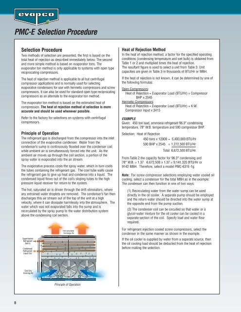
Principle of Operation<br />
The refrigerant gas is discharged from the <strong>com</strong>pressor into the inlet<br />
connection of the evaporative condenser. Water from the<br />
condenser’s sump is continuously flooded over the condenser coil,<br />
while ambient air is simultaneously forced into the unit. As the<br />
ambient air moves up through the coil section, a portion of the<br />
spray water is evaporated into the air stream.<br />
The evaporative process cools the spray water, which in turn cools<br />
the tubes containing the refrigerant gas. The cool tube walls cause<br />
the refrigerant gas to give up heat and condense into a liquid. The<br />
condensed liquid flows out of the coil’s sloping tubes to the high<br />
pressure liquid receiver for return to the system.<br />
The hot, saturated air is driven through the drift eliminators, where<br />
any entrained water droplets are removed. The condenser’s fan then<br />
discharges this air stream out of the top of the unit at a high<br />
velocity, where it can dissipate harmlessly into the atmosphere. The<br />
water which was not evaporated falls into the sump and is<br />
recirculated by the spray pump to the water distribution system<br />
above the condensing coil section.<br />
Superheated<br />
Refrigerant<br />
Gas In<br />
Condensed<br />
Refrigerant<br />
Liquid Out<br />
Cool Dry<br />
Entering Air<br />
Hot Saturated<br />
Discharge Air<br />
Principle of Operation<br />
Heat of Rejection Method<br />
In the heat of rejection method, a factor for the specified operating<br />
conditions (condensing temperature and wet bulb) is obtained from<br />
Table 1 or 2 and multiplied times the heat of rejection.<br />
The resultant figure is used to select a unit from Table 3. Unit<br />
capacities are given in Table 3 in thousands of BTU/Hr or MBH.<br />
If the heat of rejection is not known, it can be determined by one of<br />
the following formulas:<br />
Open Compressors:<br />
Heat of Rejection = Evaporator Load (BTU/Hr) + Compressor<br />
BHP x 2545<br />
Hermetic Compressors:<br />
Heat of Rejection = Evaporator Load (BTU/Hr) + K.W.<br />
Compressor Input x 3415<br />
EXAMPLE<br />
Given: 450 ton load, ammonia refrigerant 96.3° condensing<br />
temperature, 78° W.B. temperature and 500 <strong>com</strong>pressor BHP.<br />
Selection: Heat of Rejection<br />
450 tons x 12000 = 5,400,000 BTU/Hr<br />
500 BHP x 2545 = 1,272,500 BTU/Hr<br />
Total 6,672,500 BTU/Hr<br />
From Table 2 the capacity factor for 96.3° condensing and<br />
78° W.B. = 1.37 6,672,500 x 1.37 = 9,141,325 BTU/Hr or<br />
9142 MBH. Therefore, select a model <strong>PMC</strong>-631E-1g.<br />
Note: For screw <strong>com</strong>pressor selections employing water cooled oil<br />
cooling, select a condenser for the total MBH as in the example.<br />
The condenser can then function in one of two ways:<br />
(1) Recirculating water from the water sump can be used<br />
directly in the oil cooler. A separate pump should be employed<br />
and the return water should be directed into the water sump at<br />
the opposite end from the pump suction.<br />
(2) The condenser coil can be circuited so that water or a<br />
glycol-water mixture for the oil cooler can be cooled in a<br />
separate section of the coil. Specify load and water flow<br />
required.<br />
For refrigerant injection cooled screw <strong>com</strong>pressors, select the<br />
condenser in the same manner as shown in the example.<br />
If the oil cooler is supplied by water from a separate source, then<br />
the oil cooling load should be deducted from the heat of rejection<br />
before making the selection.