PMC-E Product Brochure - EVAPCO.com
PMC-E Product Brochure - EVAPCO.com
PMC-E Product Brochure - EVAPCO.com

You also want an ePaper? Increase the reach of your titles
YUMPU automatically turns print PDFs into web optimized ePapers that Google loves.
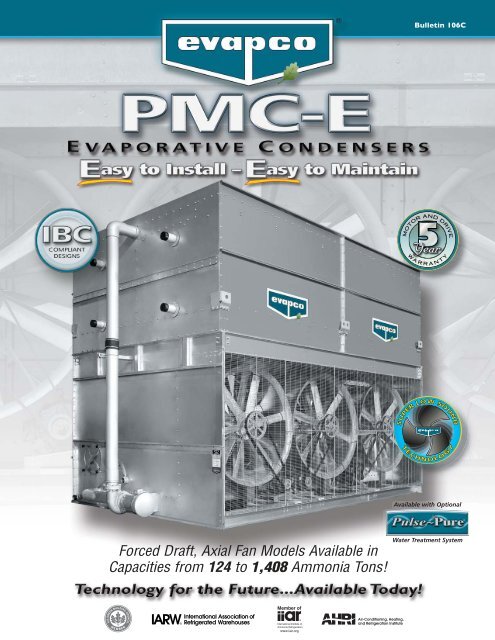
Forced Draft, Axial Fan Models Available in<br />
Capacities from 124 to 1,408 Ammonia Tons!<br />
Bulletin 106C<br />
MOTOR AND DRIVE<br />
WA R R A N T Y<br />
SOUND<br />
SOUND<br />
LOW<br />
LOW<br />
SSUPER<br />
SUPER<br />
TECHNOLOGY<br />
TECHNOLOGY<br />
Available with Optional<br />
Water Treatment System
2<br />
Since its founding in 1976, <strong>EVAPCO</strong>, Incorporated has<br />
be<strong>com</strong>e an industry leader in the engineering and<br />
manufacturing of quality heat transfer products around the<br />
world. <strong>EVAPCO</strong>’s mission is to provide first class service<br />
and quality products for the following markets:<br />
� Industrial Refrigeration<br />
� Commercial HVAC<br />
� Industrial Process<br />
� Power<br />
<strong>EVAPCO</strong>’s powerful <strong>com</strong>bination of financial strength and<br />
technical expertise has established the <strong>com</strong>pany as a<br />
recognized manufacturer of market-leading products on a<br />
worldwide basis. <strong>EVAPCO</strong> is also recognized for the superior<br />
technology of their environmentally friendly product<br />
innovations in sound reduction and water management.<br />
<strong>EVAPCO</strong> is an employee owned <strong>com</strong>pany with a strong<br />
emphasis on research & development and modern<br />
manufacturing plants. <strong>EVAPCO</strong> has earned a reputation for<br />
technological innovation and superior product quality by<br />
featuring products that are designed to offer these<br />
operating advantages:<br />
� Higher System Efficiency<br />
� Environmentally Friendly<br />
� Lower Annual Operating Costs<br />
� Reliable, Simple Operation and Maintenance<br />
With an ongoing <strong>com</strong>mitment to Research & Development<br />
programs, <strong>EVAPCO</strong> provides the most advanced products in<br />
the industry – Technology for the Future, Available Today!<br />
<strong>EVAPCO</strong> products are manufactured in 17 locations in 8<br />
countries around the world and supplied through a sales<br />
network consisting of over 170 offices.<br />
©2010 <strong>EVAPCO</strong>, Inc.<br />
<strong>PMC</strong>-E Design<br />
The industry standard for forced draft<br />
and benefits that make it Easy to<br />
NEW<br />
®<br />
ZM ZMII<br />
II<br />
MAINTENANCE<br />
MAINTENANCE<br />
ZERO<br />
ZERO<br />
PP SS RR AY AY NN OO ZZ ZZ LL EE<br />
PVC Water Distribution with ZM ® II Nozzles<br />
• Large orifice prevents clogging (no moving parts).<br />
• Redesigned nozzles for superior water distribution.<br />
• Threaded nozzles eliminate troublesome grommets.<br />
• Fixed position require zero maintenance.<br />
• Threaded end caps for ease of cleaning.<br />
• Guaranteed for life.<br />
Thermal Pak ® II Heat Transfer Technology<br />
• More surface area per plan area than<br />
<strong>com</strong>petitive designs.<br />
• Improved heat transfer efficiency due to tube<br />
geometry and orientation of tubes.<br />
• Lower refrigerant charge.<br />
• Optional TITAN stainless steel coil technology.<br />
Improved Water Distribution Piping<br />
• Horizontally mounted pumps allow for reduced<br />
basin water level.*<br />
• Simplified piping for easier basin access.<br />
• Totally enclosed pump motors assure long,<br />
trouble-free life.<br />
*Refer to engineering data for availability.<br />
NEW<br />
Optional<br />
Super Low Sound Fan<br />
(Shown in Photograph)<br />
• Extremely wide chord fan blades<br />
for sound sensitive applications.<br />
• One piece molded heavy duty<br />
construction.<br />
• 10-13 dB(A) sound reduction on<br />
fan side at 50 ft.
and Construction Features<br />
axial fan condensers. The <strong>PMC</strong>-E is equipped with owner-oriented features<br />
install...Easy to maintain...Easy on the operating budget...The Easy Choice!<br />
Sloped Pan Bottom<br />
• Pan bottom slopes to drain.<br />
• Easy to clean.<br />
• Stainless steel strainer resists corrosion.<br />
NEW<br />
MOTOR AND DRIVE<br />
WA R R A N T Y<br />
Individual Fan Drive System<br />
Water Saver Drift Eliminators<br />
• New patented design reduces drift rate to 0.001%.<br />
• Saves water and reduces water treatment cost.<br />
• Greater structural integrity vs.old style blade-type.<br />
• Recessed into casing for greater protection.<br />
U.S. Patent No. 6315804<br />
• Increased flexibility for improved capacity control.<br />
• Greater reliability through redundancy.<br />
• Easy motor replacement.<br />
• Front mounted drives for improved maintenance accessibility.<br />
Double-Brake<br />
Flange Joints<br />
• Stronger than single-brake<br />
designs by others.<br />
• Greater structural integrity.<br />
• Minimizes water leaks at<br />
field joints.<br />
Unique Field Seam<br />
• Eliminates up to 85% of fasteners.<br />
• Self guiding channels improve quality<br />
of field seam to eliminate leaks.<br />
• Easy to install.<br />
• Lower installation cost.<br />
Optional Design Features:<br />
• Man-sized Access Doors.<br />
• External Service Platforms.<br />
• Tandem Fan Drive System<br />
(Standard Fan Only).<br />
• Stainless Steel Construction.<br />
Optional Man-sized Access Door<br />
3
<strong>PMC</strong>-E Design Features<br />
4<br />
Proven Performance & Design Flexibility<br />
The new <strong>PMC</strong>-E Evaporative Condenser offers more capacity and greater<br />
system design flexibility than ever before. <strong>EVAPCO</strong>'s research and development<br />
team has invested hundreds of hours in laboratory testing to develop the next<br />
generation in Forced Draft Condenser Technology. These efforts have produced<br />
a totally new fan section design which is now <strong>com</strong>bined with the proven<br />
Thermal-Pak II ® coil technology to offer improved condenser performance.<br />
The <strong>PMC</strong>-E features more plan area options and fan horsepower options for the<br />
system design engineer. With more condenser capacity, more plan area options<br />
and greater flexibility in motor selection, the design engineer can now match the<br />
condenser performance to the specific application requirements. More equipment<br />
choices and more design flexibility mean greater value for the End-User.<br />
Thermal-Pak II ® Coil Design<br />
Lower Refrigerant Charge<br />
Only <strong>EVAPCO</strong> condensers offer the unique Thermal-Pak II ® Coil which assures greater operating<br />
efficiency in your condenser. Its unique elliptical tube design allows for closer tube spacing<br />
resulting in more surface area per plan area than traditional round tube designs. The Thermal-<br />
Pak II ® Coil design has lower resistance to air flow and permits greater water loading, making<br />
the Thermal-Pak II ® Coil the most efficient design available. And now with its new tube circuiting<br />
and orientation pattern, the Thermal-Pak II ® coil yields a lower refrigerant charge.<br />
Energy Efficient for Lowest Operating Cost<br />
Round Tube Coil by Others<br />
Lower Horsepower Options<br />
The new fan drive system of the <strong>PMC</strong>-E utilizes larger diameter vane-axial fans in a two stage arrangement to provide more<br />
efficient air flow and reduced power consumption. When <strong>com</strong>pared to the traditional centrifugal fan condenser models, the<br />
vane-axial fan design can offer up to a 50% reduction in energy consumption. And, with the new <strong>PMC</strong>-E model selections<br />
even more low horsepower options are available to obtain greater energy savings.<br />
Individual Fan Drive System<br />
Capacity Control Flexibility & Operating Redundancy<br />
The new <strong>PMC</strong>-E fan drive system provides individual motor to fan configuration as standard<br />
equipment on all models. The dedicated fan to motor arrangement ensures less “wear &<br />
tear” on the drive system versus tandem fan motor drive arrangements resulting in less<br />
maintenance. The individual motor to fan design offers greater capacity control flexibility to<br />
match the system load requirements. In addition, all Evapco condensers are equipped with<br />
an internal baffle system which extends from the pan bottom vertically through the coil<br />
bundle. This unique design allows the user to cycle fan motors independently without<br />
harmful effects of air by-pass inside the unit. The individual motor to fan design ensures<br />
maximum operating redundancy in the condenser fan system when critical operation is<br />
necessary. The <strong>PMC</strong>-E <strong>com</strong>es standard with a 5 Year motor and drive warranty.<br />
Inverter Duty Motors<br />
STANDARD!<br />
Thermal-Pak II ® Coil by <strong>EVAPCO</strong><br />
Inverter Duty motors are standard on <strong>PMC</strong>-E Condensers. Inverter Duty motors are totally enclosed, premium efficiency and inverter<br />
capable (VFD by others).<br />
Note: Variable Frequency Drive control may require other <strong>com</strong>ponent modification such as motor shaft grounding brushes, AC<br />
load reactors, low pass filters and tuned trap filters to ensure proper motor performance and service life.
Easy Field Assembly<br />
Fewer Fasteners<br />
Lower Installed Cost<br />
The <strong>PMC</strong>-E features a new field seam design which ensures easier assembly and<br />
fewer field seam leaks. The field seam incorporates new self-guiding channels to<br />
guide the coil casing section into position and set in place on the bottom fan<br />
section of the condenser. In addition, the design eliminates up to 85% of the<br />
required fasteners typically used to join the condenser sections in the field<br />
significantly reducing the contractor labor costs for installation.<br />
Improved Maintenance<br />
Fan Drive Accessibility<br />
The drive <strong>com</strong>ponents of the <strong>PMC</strong>-E are easily accessed for routine maintenance from the front of the unit. Bearing grease<br />
fittings are extended to the outside of the unit for ease of lubrication. All drive sheaves have been relocated to the front of the<br />
fan section and motors are positioned on a platform base to allow for easy belt tension adjustment.<br />
Easy Clean Sloped Basin<br />
The <strong>PMC</strong>-E basin is designed to improve maintenance access and make<br />
it easier for operating technicians to clean. The bottom of the pan is<br />
sloped to the unit drain to ensure that the basin will <strong>com</strong>pletely drain<br />
and allow sediment and debris that may collect in the basin to be easily<br />
flushed from the unit. The design helps to prevent buildup of<br />
sedimentary deposits, biological films and standing water. In addition,<br />
Evapco offers a special “man-sized” access door option to improve<br />
access to this critical area of the unit.<br />
Construction Features<br />
Unique Seam Design–Eliminate Field Leaks<br />
The new <strong>PMC</strong>-E features Evapco's unique panel construction design which<br />
includes a special butyl tape sealer with an integral sealing gasket. Each joint is<br />
then backed with a secondary caulking <strong>com</strong>pound and encased in a double-brake<br />
flange for added strength and structural integrity. This unique sealing system has<br />
been proven effective in both laboratory tests and years of field application.<br />
Superior Water Saver Drift Eliminators<br />
The <strong>PMC</strong>-E condensers incorporate a patented* highly efficient PVC drift<br />
eliminator. The eliminator removes entrained water droplets from the air stream<br />
to limit the drift rate to less than 0.001% of the recirculating water rate. With a<br />
low drift rate, <strong>PMC</strong>-E condensers save valuable water and water treatment<br />
chemicals. The eliminators feature a honey<strong>com</strong>b design which offers greater<br />
structural integrity and are recessed in the top of the casing and UV protected<br />
for longer life. They are constructed of inert polyvinyl chloride (PVC) which<br />
eliminates corrosion in this critical area of the condenser. The eliminators are<br />
assembled in sections for easy handling and removal for coil and water<br />
distribution system inspection.<br />
*U.S. Patent No. 6315804<br />
Overlay<br />
Sealant<br />
Integral<br />
Compression<br />
Shim<br />
Anti-Leak<br />
Sealer Strip<br />
5
IBC Compliance<br />
6<br />
IBC Compliance<br />
<strong>EVAPCO</strong> has been applying advanced structural technology to<br />
evaporative condensers for many years. Following seismic<br />
events in the mid 1990’s <strong>EVAPCO</strong> introduced the UB Series of<br />
induced draft cooling towers, fluid coolers and evaporative<br />
condensers. These products were designed, built and<br />
independently certified for extreme seismic and wind forces.<br />
With the advent of the International Building Code, <strong>EVAPCO</strong> is<br />
now offering a new line of <strong>PMC</strong>-E Evaporative Condensers that<br />
are IBC 2006 <strong>com</strong>pliant as standard construction.<br />
International Building Code<br />
The International Building Code (IBC) is a <strong>com</strong>prehensive set of<br />
regulations addressing the structural design and installation<br />
requirements for building systems – including HVAC and<br />
industrial refrigeration equipment. As of June 2008, all 50 states<br />
plus Washington D.C have adopted the International Building<br />
Code. Compared to previous building codes that solely<br />
examined anchorage, the earthquake provisions contained within<br />
the International Building Code address anchorage, structural<br />
integrity, and operational capability of a <strong>com</strong>ponent following a<br />
seismic event. The goal of the IBC is to minimize the loss of life<br />
and improve the capability of essential facilities to operate after a<br />
seismic event.<br />
The International Building Code (IBC) was developed to replace<br />
the BOCA National Building Code, ICBO’s Uniform Building Code<br />
and SBCCI’s Standard Building Code. The International Building<br />
Code specifies that all <strong>com</strong>ponents be designed to resist the<br />
equivalent seismic forces as the structure to which they are<br />
installed whereas previous building codes focused exclusively on<br />
the structure of the building to provide resistance against<br />
seismic forces. These <strong>com</strong>ponents include all aspects of the<br />
building architectural, electrical and mechanical systems. The<br />
failure of these <strong>com</strong>ponents during a seismic event has been a<br />
<strong>com</strong>mon occurrence in recent history. Although the structure of<br />
the building may be relatively undamaged from an earthquake,<br />
the damage to the nonstructural <strong>com</strong>ponents could be<br />
significant and result in considerable secondary damage to the<br />
building (ie. flooding, fire, structural damage).<br />
Seismic Design<br />
The IBC specifies that all installed <strong>com</strong>ponents must meet the<br />
requirements of ASCE 7-05 (American Society of Civil Engineers,<br />
Minimum Design Loads for Buildings and Other Structures).<br />
Exemptions noted in the code are for all mechanical <strong>com</strong>ponents<br />
assigned to seismic design categories A or B. ASCE 7-05<br />
explicitly states that in addition to the attachment and supports,<br />
the <strong>com</strong>ponent itself must be designed to withstand the seismic<br />
forces prescribed in the code. Simply stated, the code provisions<br />
require that evaporative cooling equipment and all other<br />
<strong>com</strong>ponents permanently installed on a structure must meet the<br />
same seismic design criteria as the building.<br />
The seismic design force, utilized for <strong>com</strong>ponent design,<br />
represents an equivalent static force that is applied to the<br />
<strong>com</strong>ponents’ center of gravity as described in the following<br />
equation:<br />
F p = [(0.4 * (a p) * (S DS) * (W p)) / (R p / I p)] * (1 + 2 * (z / h))<br />
Fp = Seismic Design Force centered at the <strong>com</strong>ponent’s center<br />
of gravity<br />
SDS = Design spectral response acceleration, short period<br />
ap = Component amplification factor<br />
Ip = Component importance factor<br />
Wp = Component operating weight<br />
Rp = Component response modification factor<br />
z = Height in structure of point of attachment of <strong>com</strong>ponent with<br />
respect to the base<br />
h = Average roof height of structure with respect to the base<br />
The minimum and maximum design force limits are specified as:<br />
Fp-min = 0.3 SDS Ip Wp Fp-max = 1.6 SDS Ip Wp A series of charts and graphs are used to determine the<br />
appropriate factors based on the location of the installation and<br />
ultimately the “importance” of the facility. A chart of the<br />
potential seismic activity in the United States is shown below.<br />
Map courtesy US Geological Survey website<br />
Highest Hazard<br />
32+<br />
24-32<br />
16-24<br />
%g 8-16<br />
4-8<br />
2-4<br />
0-2<br />
Lowest Hazard
IBC Compliance<br />
Importance Factor (Ip)<br />
A major parameter that must be determined prior to calculating<br />
the seismic design force is the <strong>com</strong>ponent importance factor<br />
(Ip). ASCE 7-05 defines the <strong>com</strong>ponent importance factor as:<br />
Importance<br />
Factor, Ip<br />
1.5<br />
Classification<br />
• Life safety <strong>com</strong>ponent required to<br />
function after seismic event.<br />
• Component containing hazardous content<br />
• Components installed at Group III<br />
(essential) facilities<br />
1.0 All other <strong>com</strong>ponents<br />
<strong>Product</strong>s such as ammonia refrigerant condensers should<br />
always be assigned an importance factor of 1.5 since they<br />
contain ammonia. The IBC identifies ammonia as hazardous<br />
content in reference of OSHA standards. According to the<br />
American Society of Civil Engineers (ASCE) Manual, 07-05<br />
edition, section 13.1.3, hazardous materials require an<br />
importance factor of 1.5.<br />
Certificate of Compliance<br />
LSTE, LPT and PMTQ Cooling Towers<br />
PMWQ, LSWE, LRWB Closed Circuit Coolers<br />
<strong>PMC</strong>-E, LSC-E and LRC Evaporative Condensers<br />
Are certified to meet or exceed the Seismic and Wind Load Provisions<br />
set forth in the applicable building codes for this project.<br />
These products have been manufactured following all<br />
applicable quality assurance programs.<br />
Applicable Building Codes:<br />
IBC 2006<br />
ASCE-7<br />
NFPA 5000<br />
Referenced Report:<br />
VMA-43387<br />
Approval Agency:<br />
VMC Seismic Consulting Group<br />
<strong>EVAPCO</strong>...Specialists in Heat Transfer <strong>Product</strong>s and Services. FD IBC COC 001<br />
Design Implementation<br />
In order to achieve this goal, an architect or civil engineer is<br />
responsible for analyzing the soil and the design of a structure<br />
to determine the factors to be used. A mechanical consulting<br />
engineer and/or design build contractor applies these factors to<br />
advise the manufacturer on the proper design for the<br />
application. <strong>EVAPCO</strong> takes this information and determines the<br />
necessary equipment to meet IBC regulations. Evapco then<br />
determines the condenser design requirements based on the<br />
IBC criteria. The standard <strong>PMC</strong>-E design is independently<br />
certified to meet the 1g IBC <strong>com</strong>pliance factors. For<br />
applications that require a more severe seismic duty, <strong>EVAPCO</strong><br />
offers an optional 5.12g construction design. This process<br />
ensures that the mechanical equipment and its <strong>com</strong>ponents are<br />
seismically <strong>com</strong>pliant per the provisions of the International<br />
Building Code.<br />
Independent Certification<br />
As required by the International Building Code, <strong>EVAPCO</strong><br />
supplies a certificate of <strong>com</strong>pliance as part of its submittal<br />
documents. The certificate of <strong>com</strong>pliance should demonstrate<br />
that the equipment/unit has been independently tested and<br />
analyzed in accordance with the IBC program. Evapco has<br />
worked closely with Vibrations Mountings and Controls Group<br />
(VMC) to <strong>com</strong>plete the independent equipment testing and<br />
analysis. A sample of the certificate of <strong>com</strong>pliance and unit<br />
label is presented below:<br />
Seismic and Wind Load Certification<br />
LSTE, LPT and PMTQ Cooling Towers<br />
PMWQ, LSWE and LRWB Closed Circuit Coolers<br />
<strong>PMC</strong>-E, LSC-E and LRC Evaporative Condensers<br />
IBC<br />
Serial<br />
Number:<br />
43387<br />
Units Designed and Manufactured to Meet the<br />
Seismic & Wind Load Requirements of:<br />
IBC 2006 ASCE-7 NFPA 5000<br />
Independent Certification By:<br />
15-248PA<br />
7
<strong>PMC</strong>-E Selection Procedure<br />
8<br />
Selection Procedure<br />
Two methods of selection are presented, the first is based on the<br />
total heat of rejection as described immediately below. The second<br />
and more simple method is based on evaporator tons. The<br />
evaporator ton method is only applicable to systems with open type<br />
reciprocating <strong>com</strong>pressors.<br />
The heat of rejection method is applicable to all but centrifugal<br />
<strong>com</strong>pressor applications and is normally used for selecting<br />
evaporative condensers for use with hermetic <strong>com</strong>pressors and screw<br />
<strong>com</strong>pressors. It can also be used for standard open type reciprocating<br />
<strong>com</strong>pressors as an alternate to the evaporator ton method.<br />
The evaporator ton method is based on the estimated heat of<br />
<strong>com</strong>pression. The heat of rejection method of selection is more<br />
accurate and should be used whenever possible.<br />
Refer to the factory for selections on systems with centrifugal<br />
<strong>com</strong>pressors.<br />
Principle of Operation<br />
The refrigerant gas is discharged from the <strong>com</strong>pressor into the inlet<br />
connection of the evaporative condenser. Water from the<br />
condenser’s sump is continuously flooded over the condenser coil,<br />
while ambient air is simultaneously forced into the unit. As the<br />
ambient air moves up through the coil section, a portion of the<br />
spray water is evaporated into the air stream.<br />
The evaporative process cools the spray water, which in turn cools<br />
the tubes containing the refrigerant gas. The cool tube walls cause<br />
the refrigerant gas to give up heat and condense into a liquid. The<br />
condensed liquid flows out of the coil’s sloping tubes to the high<br />
pressure liquid receiver for return to the system.<br />
The hot, saturated air is driven through the drift eliminators, where<br />
any entrained water droplets are removed. The condenser’s fan then<br />
discharges this air stream out of the top of the unit at a high<br />
velocity, where it can dissipate harmlessly into the atmosphere. The<br />
water which was not evaporated falls into the sump and is<br />
recirculated by the spray pump to the water distribution system<br />
above the condensing coil section.<br />
Superheated<br />
Refrigerant<br />
Gas In<br />
Condensed<br />
Refrigerant<br />
Liquid Out<br />
Cool Dry<br />
Entering Air<br />
Hot Saturated<br />
Discharge Air<br />
Principle of Operation<br />
Heat of Rejection Method<br />
In the heat of rejection method, a factor for the specified operating<br />
conditions (condensing temperature and wet bulb) is obtained from<br />
Table 1 or 2 and multiplied times the heat of rejection.<br />
The resultant figure is used to select a unit from Table 3. Unit<br />
capacities are given in Table 3 in thousands of BTU/Hr or MBH.<br />
If the heat of rejection is not known, it can be determined by one of<br />
the following formulas:<br />
Open Compressors:<br />
Heat of Rejection = Evaporator Load (BTU/Hr) + Compressor<br />
BHP x 2545<br />
Hermetic Compressors:<br />
Heat of Rejection = Evaporator Load (BTU/Hr) + K.W.<br />
Compressor Input x 3415<br />
EXAMPLE<br />
Given: 450 ton load, ammonia refrigerant 96.3° condensing<br />
temperature, 78° W.B. temperature and 500 <strong>com</strong>pressor BHP.<br />
Selection: Heat of Rejection<br />
450 tons x 12000 = 5,400,000 BTU/Hr<br />
500 BHP x 2545 = 1,272,500 BTU/Hr<br />
Total 6,672,500 BTU/Hr<br />
From Table 2 the capacity factor for 96.3° condensing and<br />
78° W.B. = 1.37 6,672,500 x 1.37 = 9,141,325 BTU/Hr or<br />
9142 MBH. Therefore, select a model <strong>PMC</strong>-631E-1g.<br />
Note: For screw <strong>com</strong>pressor selections employing water cooled oil<br />
cooling, select a condenser for the total MBH as in the example.<br />
The condenser can then function in one of two ways:<br />
(1) Recirculating water from the water sump can be used<br />
directly in the oil cooler. A separate pump should be employed<br />
and the return water should be directed into the water sump at<br />
the opposite end from the pump suction.<br />
(2) The condenser coil can be circuited so that water or a<br />
glycol-water mixture for the oil cooler can be cooled in a<br />
separate section of the coil. Specify load and water flow<br />
required.<br />
For refrigerant injection cooled screw <strong>com</strong>pressors, select the<br />
condenser in the same manner as shown in the example.<br />
If the oil cooler is supplied by water from a separate source, then<br />
the oil cooling load should be deducted from the heat of rejection<br />
before making the selection.
Table 1 - HCFC-22 and HFC-134a Heat Rejection Factors<br />
Condensing<br />
Pres. psig<br />
HCFC- HFC-<br />
22 134a<br />
Cond.<br />
Temp.<br />
°F<br />
50 55 60 62 64 66 68<br />
Wet Bulb Temperature, (°F)<br />
70 72 74 75 76 77 78 80 82 84 86<br />
156 95 85 1.10 1.22 1.39 1.50 1.61 1.75 1.93 2.13 2.42 2.78 3.02 3.29 3.64 4.00 - - - -<br />
168 104 90 .93 1.02 1.14 1.21 1.28 1.36 1.45 1.57 1.71 1.89 2.00 2.12 2.25 2.38 2.85 3.50 - -<br />
182 114 95 .80 .87 .95 1.00 1.05 1.10 1.15 1.22 1.31 1.40 1.45 1.50 1.56 1.64 1.82 2.07 2.37 2.77<br />
196 124 100 .71 .76 .82 .85 .88 .91 .94 .98 1.03 1.09 1.12 1.15 1.20 1.24 1.34 1.46 1.63 1.82<br />
211 135 105 .63 .66 .70 .72 .75 .77 .80 .83 .87 .91 .93 .95 .97 1.00 1.06 1.13 1.23 1.35<br />
226 146 110 .56 .59 .62 .64 .65 .67 .69 .71 .74 .77 .78 .80 .82 .84 .88 .93 .98 1.04<br />
Note: Consult factory for selections using other refrigerants.<br />
Table 2 - Ammonia (R-717) Heat Rejection Factors<br />
Condensing<br />
Pres.<br />
Cond.<br />
Temp.<br />
Wet Bulb Temperature, (°F)<br />
psig °F<br />
50 55 60 62 64 66 68 70 72 74 75 76 77 78 80 82 84 86<br />
152 85 .98 1.09 1.24 1.34 1.44 1.56 1.72 1.90 2.16 2.48 2.70 2.94 3.25 3.57 - - - -<br />
166 90 .83 .91 1.02 1.08 1.14 1.21 1.29 1.40 1.53 1.69 1.79 1.89 2.01 2.12 2.54 3.12 - -<br />
181 95 .71 .78 .85 .89 .94 .98 1.03 1.09 1.17 1.25 1.29 1.34 1.39 1.47 1.63 1.85 2.12 2.47<br />
185 96.3 .69 .75 .82 .86 .90 .94 .98 1.03 1.10 1.18 1.22 1.26 1.31 1.37 1.51 1.71 1.94 2.25<br />
197 100 .63 .68 .73 .76 .79 .81 .84 .87 .92 .97 1.00 1.03 1.07 1.11 1.20 1.30 1.46 1.63<br />
214 105 .56 .59 .62 .64 .67 .69 .71 .74 .78 .81 .83 .85 .87 .89 .95 1.01 1.10 1.21<br />
232 110 .50 .53 .55 .57 .58 .60 .62 .63 .66 .69 .70 .71 .73 .75 .79 .83 .87 .93<br />
Table 3 - Unit Heat Rejection<br />
Model MBH Base<br />
<strong>PMC</strong>-175E-1g 2572.5<br />
<strong>PMC</strong>-190E-1g 2793.0<br />
<strong>PMC</strong>-210E-1g 3087.0<br />
<strong>PMC</strong>-220E-1g 3234.0<br />
<strong>PMC</strong>-235E-1g 3454.5<br />
<strong>PMC</strong>-240E-1g 3528.0<br />
<strong>PMC</strong>-250E-1g 3675.0<br />
<strong>PMC</strong>-275E-1g 4042.5<br />
<strong>PMC</strong>-295E-1g 4336.5<br />
<strong>PMC</strong>-325E-1g 4777.5<br />
<strong>PMC</strong>-332E-1g 4880.4<br />
<strong>PMC</strong>-335E-1g 4924.5<br />
<strong>PMC</strong>-360E-1g 5292.0<br />
<strong>PMC</strong>-369E-1g 5424.3<br />
<strong>PMC</strong>-375E-1g 5512.5<br />
<strong>PMC</strong>-386E-1g 5674.2<br />
<strong>PMC</strong>-397E-1g 5835.9<br />
<strong>PMC</strong>-400E-1g 5880.0<br />
<strong>PMC</strong>-420E-1g 6174.0<br />
<strong>PMC</strong>-426E-1g 6262.2<br />
Model MBH Base<br />
<strong>PMC</strong>-428E-1g 6291.6<br />
<strong>PMC</strong>-431E-1g 6335.7<br />
<strong>PMC</strong>-450E-1g 6615.0<br />
<strong>PMC</strong>-457E-1g 6717.9<br />
<strong>PMC</strong>-464E-1g 6820.8<br />
<strong>PMC</strong>-481E-1g 7070.7<br />
<strong>PMC</strong>-488E-1g 7173.6<br />
<strong>PMC</strong>-492E-1g 7232.4<br />
<strong>PMC</strong>-495E-1g 7276.5<br />
<strong>PMC</strong>-503E-1g 7394.1<br />
<strong>PMC</strong>-515E-1g 7570.5<br />
<strong>PMC</strong>-519E-1g 7629.3<br />
<strong>PMC</strong>-536E-1g 7879.2<br />
<strong>PMC</strong>-558E-1g 8202.6<br />
<strong>PMC</strong>-559E-1g 8217.3<br />
<strong>PMC</strong>-564E-1g 8290.8<br />
<strong>PMC</strong>-591E-1g 8687.7<br />
<strong>PMC</strong>-596E-1g 8761.2<br />
<strong>PMC</strong>-601E-1g 8834.7<br />
<strong>PMC</strong>-605E-1g 8893.5<br />
Model MBH Base<br />
<strong>PMC</strong>-631E-1g 9275.7<br />
<strong>PMC</strong>-634E-1g 9319.8<br />
<strong>PMC</strong>-636E-1g 9349.2<br />
<strong>PMC</strong>-645E-1g 9481.5<br />
<strong>PMC</strong>-679E-1g 9981.3<br />
<strong>PMC</strong>-688E-1g 10113.6<br />
<strong>PMC</strong>-690E-1g 10143.0<br />
<strong>PMC</strong>-691E-1g 10157.7<br />
<strong>PMC</strong>-719E-1g 10569.3<br />
<strong>PMC</strong>-723E-1g 10628.1<br />
<strong>PMC</strong>-731E-1g 10745.7<br />
<strong>PMC</strong>-737E-1g 10833.9<br />
<strong>PMC</strong>-772E-1g 11348.4<br />
<strong>PMC</strong>-774E-1g 11377.8<br />
<strong>PMC</strong>-778E-1g 11436.6<br />
<strong>PMC</strong>-800E-1g 11760.0<br />
<strong>PMC</strong>-801E-1g 11774.7<br />
<strong>PMC</strong>-811E-1g 11921.7<br />
<strong>PMC</strong>-831E-1g 12215.7<br />
<strong>PMC</strong>-840E-1g 12348.0<br />
Model MBH Base<br />
<strong>PMC</strong>-852E-1g 12524.4<br />
<strong>PMC</strong>-853E-1g 12539.1<br />
<strong>PMC</strong>-856E-1g 12583.2<br />
<strong>PMC</strong>-863E-1g 12686.1<br />
<strong>PMC</strong>-888E-1g 13053.6<br />
<strong>PMC</strong>-889E-1g 13068.3<br />
<strong>PMC</strong>-894E-1g 13141.8<br />
<strong>PMC</strong>-895E-1g 13156.5<br />
<strong>PMC</strong>-900E-1g 13230.0<br />
<strong>PMC</strong>-929E-1g 13656.3<br />
<strong>PMC</strong>-939E-1g 13803.3<br />
<strong>PMC</strong>-940E-1g 13818.0<br />
<strong>PMC</strong>-949E-1g 13950.3<br />
<strong>PMC</strong>-956E-1g 14053.2<br />
<strong>PMC</strong>-962E-1g 14141.4<br />
<strong>PMC</strong>-974E-1g 14317.8<br />
<strong>PMC</strong>-976E-1g 14347.2<br />
<strong>PMC</strong>-983E-1g 14450.1<br />
<strong>PMC</strong>-989E-1g 14538.3<br />
<strong>PMC</strong>-992E-1g 14582.4<br />
Model MBH Base<br />
<strong>PMC</strong>-1006E-1g 14788.2<br />
<strong>PMC</strong>-1024E-1g 15052.8<br />
<strong>PMC</strong>-1038E-1g 15258.6<br />
<strong>PMC</strong>-1071E-1g 15743.7<br />
<strong>PMC</strong>-1073E-1g 15773.1<br />
<strong>PMC</strong>-1088E-1g 15993.6<br />
<strong>PMC</strong>-1116E-1g 16405.2<br />
<strong>PMC</strong>-1117E-1g 16419.9<br />
<strong>PMC</strong>-1125E-1g 16537.5<br />
<strong>PMC</strong>-1127E-1g 16566.9<br />
<strong>PMC</strong>-1180E-1g 17346.0<br />
<strong>PMC</strong>-1182E-1g 17375.4<br />
<strong>PMC</strong>-1189E-1g 17478.3<br />
<strong>PMC</strong>-1201E-1g 17654.7<br />
<strong>PMC</strong>-1203E-1g 17684.1<br />
<strong>PMC</strong>-1211E-1g 17801.7<br />
<strong>PMC</strong>-1258E-1g 18492.6<br />
<strong>PMC</strong>-1261E-1g 18536.7<br />
<strong>PMC</strong>-1269E-1g 18654.3<br />
<strong>PMC</strong>-1275E-1g 18742.5<br />
Model MBH Base<br />
<strong>PMC</strong>-1290E-1g 18963.0<br />
<strong>PMC</strong>-1358E-1g 19962.6<br />
<strong>PMC</strong>-1376E-1g 20227.2<br />
<strong>PMC</strong>-1382E-1g 20315.4<br />
<strong>PMC</strong>-1438E-1g 21138.6<br />
<strong>PMC</strong>-1446E-1g 21256.2<br />
<strong>PMC</strong>-1473E-1g 21653.1<br />
<strong>PMC</strong>-1549E-1g 22770.3<br />
<strong>PMC</strong>-1556E-1g 22873.2<br />
<strong>PMC</strong>-1599E-1g 23505.3<br />
<strong>PMC</strong>-1625E-1g 23887.5<br />
<strong>PMC</strong>-1705E-1g 25063.5<br />
<strong>PMC</strong>-1712E-1g 25166.4<br />
<strong>PMC</strong>-1776E-1g 26107.2<br />
<strong>PMC</strong>-1788E-1g 26283.6<br />
<strong>PMC</strong>-1877E-1g 27591.9<br />
<strong>PMC</strong>-1879E-1g 27621.3<br />
<strong>PMC</strong>-1985E-1g 29179.5<br />
9
<strong>PMC</strong>-E Selection Procedure<br />
10<br />
Evaporator Ton Method<br />
In the evaporator ton method, factors for the specified<br />
operating conditions (suction temperature, condensing<br />
temperature and wet bulb) are obtained from either Table 5 or<br />
6 and multiplied times the heat load in tons. The resultant<br />
figure is used to select a unit from Table 4. The condenser<br />
model in Table 4 is equal to the unit capacity in evaporator<br />
tons for HCFC-22 or HFC-134a conditions of 105°F<br />
condensing, 40°F suction and 78° wet bulb.<br />
Table 4 - Unit Sizes<br />
Model Capacity<br />
<strong>PMC</strong>-175E-1g 175<br />
<strong>PMC</strong>-190E-1g 190<br />
<strong>PMC</strong>-210E-1g 210<br />
<strong>PMC</strong>-220E-1g 220<br />
<strong>PMC</strong>-235E-1g 235<br />
<strong>PMC</strong>-240E-1g 240<br />
<strong>PMC</strong>-250E-1g 250<br />
<strong>PMC</strong>-275E-1g 275<br />
<strong>PMC</strong>-295E-1g 295<br />
<strong>PMC</strong>-325E-1g 325<br />
<strong>PMC</strong>-332E-1g 332<br />
<strong>PMC</strong>-335E-1g 335<br />
<strong>PMC</strong>-360E-1g 360<br />
<strong>PMC</strong>-369E-1g 369<br />
<strong>PMC</strong>-375-E-1g 375<br />
<strong>PMC</strong>-386E-1g 386<br />
<strong>PMC</strong>-397E-1g 397<br />
<strong>PMC</strong>-400E-1g 400<br />
<strong>PMC</strong>-420E-1g 420<br />
<strong>PMC</strong>-426E-1g 426<br />
<strong>PMC</strong>-428E-1g 428<br />
<strong>PMC</strong>-431E-1g 431<br />
<strong>PMC</strong>-450E-1g 450<br />
<strong>PMC</strong>-457E-1g 457<br />
<strong>PMC</strong>-464E-1g 464<br />
<strong>PMC</strong>-481E-1g 481<br />
<strong>PMC</strong>-488E-1g 488<br />
<strong>PMC</strong>-492E-1g 492<br />
<strong>PMC</strong>-495E-1g 495<br />
<strong>PMC</strong>-503E-1g 503<br />
<strong>PMC</strong>-515E-1g 515<br />
<strong>PMC</strong>-519E-1g 519<br />
<strong>PMC</strong>-536E-1g 536<br />
<strong>PMC</strong>-558E-1g 558<br />
<strong>PMC</strong>-559E-1g 559<br />
<strong>PMC</strong>-564E-1g 564<br />
<strong>PMC</strong>-591E-1g 591<br />
<strong>PMC</strong>-596E-1g 596<br />
<strong>PMC</strong>-601E-1g 601<br />
<strong>PMC</strong>-605E-1g 605<br />
<strong>PMC</strong>-631E-1g 631<br />
<strong>PMC</strong>-634E-1g 634<br />
<strong>PMC</strong>-636E-1g 636<br />
<strong>PMC</strong>-645E-1g 645<br />
<strong>PMC</strong>-679E-1g 679<br />
<strong>PMC</strong>-688E-1g 688<br />
<strong>PMC</strong>-690E-1g 690<br />
<strong>PMC</strong>-691E-1g 691<br />
<strong>PMC</strong>-E Models<br />
<strong>PMC</strong>-719E-1g 719<br />
<strong>PMC</strong>-723E-1g 723<br />
<strong>PMC</strong>-731E-1g 731<br />
<strong>PMC</strong>-737E-1g 737<br />
<strong>PMC</strong>-772E-1g 772<br />
<strong>PMC</strong>-774E-1g 774<br />
<strong>PMC</strong>-778E-1g 778<br />
<strong>PMC</strong>-800E-1g 800<br />
<strong>PMC</strong>-801E-1g 801<br />
<strong>PMC</strong>-811E-1g 811<br />
<strong>PMC</strong>-831E-1g 831<br />
<strong>PMC</strong>-840E-1g 840<br />
<strong>PMC</strong>-852E-1g 852<br />
<strong>PMC</strong>-853E-1g 853<br />
<strong>PMC</strong>-856E-1g 856<br />
<strong>PMC</strong>-863E-1g 863<br />
<strong>PMC</strong>-888E-1g 888<br />
<strong>PMC</strong>-889E-1g 889<br />
<strong>PMC</strong>-894E-1g 894<br />
<strong>PMC</strong>-895E-1g 895<br />
<strong>PMC</strong>-900E-1g 900<br />
<strong>PMC</strong>-929E-1g 929<br />
<strong>PMC</strong>-939E-1g 939<br />
<strong>PMC</strong>-940E-1g 940<br />
EXAMPLE<br />
Given: 300 ton evaporator load, R-717, condensing at 95° F,<br />
with +10° F suction and 76° F wet bulb temperatures.<br />
Selection: The capacity factor from Table 6 for the given<br />
condensing and wet bulb conditions is 1.38, and the capacity<br />
factor for the suction temperature of +10° F is 1.03, so the<br />
corrected capacity required may be determined as:<br />
300 X 1.38 X 1.03 = 426 corrected tons. Therefore, select a<br />
model <strong>PMC</strong>-428E-1g, <strong>PMC</strong>-431E-1g or <strong>PMC</strong>-450E-1g<br />
depending on unit type desired, and any layout or horsepower<br />
considerations.<br />
Model Capacity Model Capacity Model Capacity Model Capacity<br />
<strong>PMC</strong>-949E-1g 949<br />
<strong>PMC</strong>-956E-1g 956<br />
<strong>PMC</strong>-962E-1g 962<br />
<strong>PMC</strong>-974E-1g 974<br />
<strong>PMC</strong>-976E-1g 976<br />
<strong>PMC</strong>-983E-1g 983<br />
<strong>PMC</strong>-989E-1g 989<br />
<strong>PMC</strong>-992E-1g 992<br />
<strong>PMC</strong>-1006E-1g 1006<br />
<strong>PMC</strong>-1024E-1g 1024<br />
<strong>PMC</strong>-1038E-1g 1038<br />
<strong>PMC</strong>-1071E-1g 1071<br />
<strong>PMC</strong>-1073E-1g 1073<br />
<strong>PMC</strong>-1088E-1g 1088<br />
<strong>PMC</strong>-1116E-1g 1116<br />
<strong>PMC</strong>-1117E-1g 1117<br />
<strong>PMC</strong>-1125E-1g 1125<br />
<strong>PMC</strong>-1127E-1g 1127<br />
<strong>PMC</strong>-1180E-1g 1180<br />
<strong>PMC</strong>-1182E-1g 1182<br />
<strong>PMC</strong>-1189E-1g 1189<br />
<strong>PMC</strong>-1201E-1g 1201<br />
<strong>PMC</strong>-1203E-1g 1203<br />
<strong>PMC</strong>-1211E-1g 1211<br />
<strong>PMC</strong>-1258E-1g 1258<br />
<strong>PMC</strong>-1261E-1g 1261<br />
<strong>PMC</strong>-1269E-1g 1269<br />
<strong>PMC</strong>-1275E-1g 1275<br />
<strong>PMC</strong>-1290E-1g 1290<br />
<strong>PMC</strong>-1358E-1g 1358<br />
<strong>PMC</strong>-1376E-1g 1376<br />
<strong>PMC</strong>-1382E-1g 1382<br />
<strong>PMC</strong>-1438E-1g 1438<br />
<strong>PMC</strong>-1446E-1g 1446<br />
<strong>PMC</strong>-1473E-1g 1473<br />
<strong>PMC</strong>-1549E-1g 1549<br />
<strong>PMC</strong>-1556E-1g 1556<br />
<strong>PMC</strong>-1599E-1g 1599<br />
<strong>PMC</strong>-1625E-1g 1625<br />
<strong>PMC</strong>-1705E-1g 1705<br />
<strong>PMC</strong>-1712E-1g 1712<br />
<strong>PMC</strong>-1776E-1g 1776<br />
<strong>PMC</strong>-1788E-1g 1788<br />
<strong>PMC</strong>-1877E-1g 1877<br />
<strong>PMC</strong>-1879E-1g 1879<br />
<strong>PMC</strong>-1985E-1g 1985
Table 5 - HCFC-22 and HFC-134a Capacity Factors<br />
Condensing<br />
Pres. psig<br />
HCFC-<br />
22<br />
HFC-<br />
134a<br />
Cond.<br />
Temp.<br />
°F<br />
Table 6 - Ammonia (R-717) Capacity Factors<br />
Condensing Cond.<br />
Pres. Temp.<br />
psig °F<br />
50 55 60 62 64 66 68 70 72 74 75 76 77 78 80 82 84 86<br />
156 95 85 1.05 1.16 1.32 1.43 1.53 1.66 1.83 2.02 2.30 2.64 2.87 3.13 3.46 3.80 - - - -<br />
168 104 90 .90 .98 1.10 1.17 1.24 1.31 1.40 1.52 1.65 1.82 1.93 2.05 2.17 2.30 2.75 3.38 - -<br />
182 114 95 .78 .85 .93 .98 1.02 1.07 1.12 1.19 1.28 1.37 1.42 1.46 1.52 1.60 1.78 2.02 2.31 2.70<br />
196 124 100 .70 .75 .81 .84 .87 .90 .93 .97 1.02 1.08 1.11 1.14 1.19 1.23 1.33 1.44 1.61 1.80<br />
211 135 105 .63 .66 .70 .72 .75 .77 .80 .83 .87 .91 .93 .95 .97 1.00 1.06 1.13 1.23 1.35<br />
226 146 110 .57 .60 .63 .65 .66 .68 .70 .72 .75 .78 .79 .81 .83 .85 .89 .94 .99 1.05<br />
Suction Temp. °F -20° -10° -0° +10° +20° +30° +40° +50°<br />
Suction Press. HCFC-22 10.1 16.5 24.0 32.8 43.0 54.9 68.5 84.0<br />
(psig)<br />
HFC-134a -1.8 1.9 6.5 11.9 18.4 26.1 35.0 45.4<br />
Capacity Factor 1.22 1.17 1.13 1.09 1.06 1.03 1.00 0.97<br />
50 55 60 62 64 66 68 70 72 74 75 76 77 78 80 82 84 86<br />
152 85 .99 1.09 1.25 1.34 1.44 1.57 1.73 1.91 2.17 2.49 2.71 2.95 3.26 3.59 - - - -<br />
166 90 .84 .93 1.03 1.10 1.16 1.23 1.32 1.42 1.55 1.71 1.81 1.92 2.04 2.16 2.59 3.17 - -<br />
181 95 .74 .80 .87 .92 .97 1.01 1.06 1.12 1.21 1.29 1.33 1.38 1.44 1.51 1.68 1.91 2.18 2.55<br />
185 96.3 .72 .78 .85 .89 .93 .97 1.01 1.07 1.14 1.22 1.26 1.30 1.35 1.41 1.56 1.76 2.01 2.33<br />
197 100 .66 .71 .76 .79 .82 .85 .87 .91 .96 1.01 1.04 1.07 1.12 1.15 1.25 1.36 1.52 1.69<br />
214 105 .59 .62 .66 .68 .71 .73 .75 .78 .82 .86 .88 .90 .91 .94 1.00 1.07 1.16 1.27<br />
232 110 .53 .56 .59 .61 .62 .64 .66 .68 .71 .73 .74 .76 .78 .80 .84 .89 .93 .99<br />
Note: Consult factory for selections using other refrigerants.<br />
Wet Bulb Temperature, (°F)<br />
Wet Bulb Temperature, (°F)<br />
Suction Temp. °F -30° -20° -10° 0° +10° +20° +30° +40°<br />
Suction Press. (psig) -1.6 3.6 9.0 15.7 23.8 33.5 45.0 58.6<br />
Capacity Factor 1.18 1.14 1.10 1.07 1.03 1.00 0.97 0.95<br />
11
Engineering & Dimensions Data<br />
<strong>PMC</strong>-175E-1g to 375E-1g<br />
U<br />
Table 7 Engineering Data<br />
* Tons at standard conditions: 96.3°F condensing, 20°F suction and 78°F W.B.<br />
** Gallons shown is water in suspension in unit and piping. Allow for additional water in bottom of remote sump to cover pump suction and strainer during operation.<br />
(12” would normally be sufficient.)<br />
† Heaviest section is the upper coil section. When 5.12 seismic design is required consult the factory for specific weights.<br />
*** Refrigerant charge is shown for R-717. Multiply by 1.93 for R-22 and 1.98 for R-134a.<br />
Dimensions are subject to change. Do not use for pre-fabrication.<br />
12<br />
30-3/8"<br />
4 B.F.W. REFRIG. IN<br />
4 B.F.W. REFRIG. OUT<br />
(2)ACCESS<br />
DOOR<br />
74-1/2”<br />
2 M.P.T.<br />
DRAIN<br />
1 M.P.T.<br />
MAKE-UP 2 F.P.T.<br />
6’ 4”<br />
OVERFLOW<br />
A<br />
77-5/8”<br />
H<br />
<strong>PMC</strong>-175E-1g to 240E-1g <strong>PMC</strong>-250E-1g to 375E-1g<br />
12-1/2" 11' 11-5/8"<br />
14"<br />
18' 1/8"<br />
Refrigerant<br />
R-717 Operating Coil<br />
Model<br />
No.<br />
Capacity<br />
Tons* HP CFM Shipping<br />
Heaviest<br />
Section† Operating<br />
Charge<br />
lbs.***<br />
Volume<br />
ft<br />
Gallons Conn. Operating Height Upper Coil<br />
3 Fans Weights (lbs)†<br />
Spray Pump Remote Sump<br />
Dimensions (in.)<br />
HP GPM Req’d** Size Weight H U A<br />
<strong>PMC</strong>-175E-1g 124 (2)5 31,300 8,090 5,220 10,410 165 22 2 345 200 8 9,360 130-3/8 57-3/8 30-3/4<br />
<strong>PMC</strong>-190E-1g 135 (2)5 34,000 8,090 5,220 10,410 165 22 2 345 200 8 9,360 130-3/8 57-3/8 30-3/4<br />
<strong>PMC</strong>-210E-1g 149 (2)5 33,500 9,050 6,180 11,400 200 28 2 345 200 8 10,350 138-7/8 65-7/8 39-1/4<br />
<strong>PMC</strong>-220E-1g 156 (2)5 33,000 10,050 7,180 12,440 240 33 2 345 200 8 11,390 147-3/8 74-3/8 47-3/4<br />
<strong>PMC</strong>-235E-1g 167 (2)7.5 36,600 9,150 6,180 11,500 200 28 2 345 200 8 10,450 138-7/8 65-7/8 39-1/4<br />
<strong>PMC</strong>-240E-1g 170 (2)7.5 35,500 10,150 7,180 12,540 240 33 2 345 200 8 11,490 147-3/8 74-3/8 47-3/4<br />
<strong>PMC</strong>-250E-1g 177 (3)5 54,000 10,570 6,210 13,990 185 25 3 515 260 10 12,040 121-7/8 48-7/8 22-1/4<br />
<strong>PMC</strong>-275E-1g 195 (3)5 48,500 12,080 7,720 15,560 240 33 3 515 260 10 13,600 130-3/8 57-3/8 30-3/4<br />
<strong>PMC</strong>-295E-1g 209 (3)5 51,900 12,080 7,720 15,560 240 33 3 515 260 10 13,600 130-3/8 57-3/8 30-3/4<br />
<strong>PMC</strong>-325E-1g 230 (3)5 50,900 13,530 9,170 17,070 300 41 3 515 260 10 15,110 138-7/8 65-7/8 39-1/4<br />
<strong>PMC</strong>-335E-1g 238 (3)5 50,300 15,030 10,670 18,630 360 49 3 515 260 10 16,670 147-3/8 74-3/8 47-3/4<br />
<strong>PMC</strong>-360E-1g 255 (3)7.5 57,000 13,690 9,170 17,230 300 41 3 515 260 10 15,270 138-7/8 65-7/8 39-1/4<br />
<strong>PMC</strong>-375E-1g 266 (3)7.5 56,300 15,190 10,670 18,790 360 49 3 515 260 10 16,830 147-3/8 74-3/8 47-3/4
Engineering & Dimensions Data<br />
<strong>PMC</strong>-332E-1g to 778E-1g<br />
30-3/8”<br />
U<br />
3 M.P.T.<br />
DRAIN<br />
2 M.P.T.<br />
MAKE-UP<br />
(2)ACCESS<br />
DOOR<br />
57”<br />
(2)4 B.F.W. REFRIG. IN<br />
(2)4 B.F.W. REFRIG. OUT<br />
9’ 9-3/4”<br />
3 F.P.T.<br />
OVERFLOW<br />
Table 8 Engineering Data<br />
A<br />
119”<br />
103-1/4”<br />
H<br />
<strong>PMC</strong>-332E-1g<br />
to<br />
519E-1g<br />
<strong>PMC</strong>-503E-1g to 778E-1g<br />
18" 11' 11-3/4"<br />
20-5/8”<br />
18’ 1/8”<br />
Refrigerant<br />
R-717 Operating Coil<br />
Model<br />
No.<br />
Capacity<br />
Tons* HP CFM Shipping<br />
Heaviest<br />
Section† Operating<br />
Charge<br />
lbs.***<br />
Volume<br />
ft<br />
Gallons Conn. Operating Height Upper Coil<br />
3 Fans Weights (lbs)†<br />
Spray Pump Remote Sump<br />
Dimensions (in.)<br />
HP GPM Req’d** Size Weight H U A<br />
<strong>PMC</strong>-332E-1g 235 (2)5 61,000 12,870 8,590 16,950 250 34 5 685 500 10 16,270 163-3/8 61 22-1/4<br />
<strong>PMC</strong>-369E-1g 262 (2)7.5 70,000 12,970 8,590 17,050 250 34 5 685 500 10 16,370 163-3/8 61 22-1/4<br />
<strong>PMC</strong>-386E-1g 274 (2)5 59,200 16,700 12,420 20,940 405 56 5 685 500 10 20,260 180-3/8 78 39-1/4<br />
<strong>PMC</strong>-397E-1g 282 (2)10 77,200 13,000 8,590 17,080 250 34 5 685 500 10 16,400 163-3/8 61 22-1/4<br />
<strong>PMC</strong>-400E-1g 284 (2)7.5 69,000 14,940 10,560 19,100 325 44 5 685 500 10 18,420 171-7/8 69-1/2 30-3/4<br />
<strong>PMC</strong>-426E-1g 302 (2)7.5 67,900 16,800 12,420 21,040 405 56 5 685 500 10 20,360 180-3/8 78 39-1/4<br />
<strong>PMC</strong>-428E-1g 304 (2)15 88,700 113,260 8,590 17,340 250 34 5 685 500 10 16,660 163-3/8 61 22-1/4<br />
<strong>PMC</strong>-431E-1g 306 (2)10 76,000 14,970 10,560 19,130 325 44 5 685 500 10 18,450 171-7/8 69-1/2 30-3/4<br />
<strong>PMC</strong>-457E-1g 324 (2)10 74,900 16,830 12,420 21,070 405 56 5 685 500 10 20,390 180-3/8 78 39-1/4<br />
<strong>PMC</strong>-464E-1g 329 (2)15 87,400 15,230 10,560 19,390 325 44 5 685 500 10 18,710 171-7/8 69-1/2 30-3/4<br />
<strong>PMC</strong>-481E-1g 341 (2)10 73,800 18,780 14,370 23,090 480 66 5 685 500 10 22,410 188-7/8 86-1/2 47-3/4<br />
<strong>PMC</strong>-492E-1g 349 (2)15 86,100 17,090 12,420 21,330 405 56 5 685 500 10 20,650 180-3/8 78 39-1/4<br />
<strong>PMC</strong>-519E-1g 368 (2)15 84,800 19,040 14,370 23,350 480 66 5 685 500 10 22,670 188-7/8 86-1/2 47-3/4<br />
<strong>PMC</strong>-503E-1g 357 (3)5 91,800 19,590 12,580 25,910 365 50 7.5 1030 620 12 23,710 163-3/8 61 22-1/4<br />
<strong>PMC</strong>-558E-1g 396 (3)7.5 105,300 19,750 12,580 26,070 365 50 7.5 1030 620 12 23,870 163-3/8 61 22-1/4<br />
<strong>PMC</strong>-596E-1g 423 (3)10 116,100 19,800 12,580 26,120 365 50 7.5 1030 620 12 23,920 163-3/8 61 22-1/4<br />
<strong>PMC</strong>-605E-1g 429 (3)7.5 103,800 22,680 15,510 29,120 485 66 7.5 1030 620 12 26,920 171-7/8 69-1/2 30-3/4<br />
<strong>PMC</strong>-636E-1g 451 (3)15 133,500 20,190 12,580 26,510 365 50 7.5 1030 620 12 24,310 163-3/8 61 22-1/4<br />
<strong>PMC</strong>-645E-1g 457 (3)10 114,400 22,730 15,510 29,170 485 66 7.5 1030 620 12 26,970 171-7/8 69-1/2 30-3/4<br />
<strong>PMC</strong>-690E-1g 489 (3)15 131,500 23,120 15,510 29,560 485 66 7.5 1030 620 12 27,360 171-7/8 69-1/2 30-3/4<br />
<strong>PMC</strong>-691E-1g 490 (3)10 112,700 25,550 18,330 32,100 600 82 7.5 1030 620 12 29,900 180-3/8 78 39-1/4<br />
<strong>PMC</strong>-719E-1g 510 (3)10 111,100 28,480 21,260 35,150 720 98 7.5 1030 620 12 32,950 188-7/8 86-1/2 47-3/4<br />
<strong>PMC</strong>-731E-1g 518 (3)15 129,600 25,940 18,330 32,490 600 82 7.5 1030 620 12 30,290 180-3/8 78 39-1/4<br />
<strong>PMC</strong>-778E-1g 552 (3)15 127,600 28,870 21,260 35,540 720 98 7.5 1030 620 12 33,340 188-7/8 86-1/2 47-3/4<br />
* Tons at standard conditions: 96.3°F condensing, 20°F suction and 78°F W.B.<br />
** Gallons shown is water in suspension in unit and piping. Allow for additional water in bottom of remote sump to cover pump suction and strainer during operation.<br />
(12” would normally be sufficient.)<br />
† Heaviest section is the upper coil section. When 5.12 seismic design is required consult the factory for specific weights.<br />
*** Refrigerant charge is shown for R-717. Multiply by 1.93 for R-22 and 1.98 for R-134a.<br />
Dimensions are subject to change. Do not use for pre-fabrication.<br />
13
Engineering & Dimensions Data<br />
<strong>PMC</strong>-772E-1g to 1556E-1g<br />
Table 8 Engineering Data<br />
14<br />
30-3/8”<br />
U<br />
3 M.P.T.<br />
DRAIN<br />
2 M.P.T.<br />
MAKE-UP<br />
(2)ACCESS<br />
DOOR<br />
57”<br />
(2)4 B.F.W. REFRIG. IN<br />
(2)4 B.F.W. REFRIG. OUT<br />
9’ 9-3/4”<br />
3 F.P.T.<br />
OVERFLOW<br />
A<br />
119”<br />
103-1/4”<br />
H<br />
<strong>PMC</strong>-772E-1g to 1038E-1g<br />
18” 24’ 7/8”<br />
16-3/8”<br />
<strong>PMC</strong>-1006E-1g to 1556E-1g<br />
20-5/8” 36’ 2”<br />
23-5/8”<br />
Refrigerant<br />
R-717 Operating Coil<br />
Model<br />
No.<br />
Capacity<br />
Tons* HP CFM Shipping<br />
Heaviest<br />
Section† Operating<br />
Charge<br />
lbs.***<br />
Volume<br />
ft<br />
Gallons Conn. Operating Height Upper Coil<br />
3 Fans Weights (lbs)†<br />
Spray Pump Remote Sump<br />
Dimensions (in.)<br />
HP GPM Req’d** Size Weight H U A<br />
<strong>PMC</strong>-772E-1g 548 (4)5 118,500 33,850 12,320 42,690 805 112 (2)5 1370 930 12 40,550 180-3/8 78 39-1/4<br />
<strong>PMC</strong>-801E-1g 568 (4)7.5 137,900 30,140 10,360 38,820 650 89 (2)5 1370 930 12 36,680 171-7/8 69-1/2 30-3/4<br />
<strong>PMC</strong>-853E-1g 605 (4)7.5 135,900 34,060 12,320 42,900 805 112 (2)5 1370 930 12 40,760 180-3/8 78 39-1/4<br />
<strong>PMC</strong>-863E-1g 612 (4)10 152,100 30,210 10,360 38,890 650 89 (2)5 1370 930 12 36,750 171-7/8 69-1/2 30-3/4<br />
<strong>PMC</strong>-888E-1g 630 (4)7.5 133,900 38,160 14,370 47,150 960 131 (2)5 1370 930 12 45,010 188-7/8 86-1/2 47-3/4<br />
<strong>PMC</strong>-929E-1g 659 (4)15 174,800 30,730 10,360 39,410 650 89 (2)5 1370 930 12 37,270 171-7/8 69-1/2 30-3/4<br />
<strong>PMC</strong>-962E-1g 682 (4)10 147,600 38,230 14,370 47,220 960 131 (2)5 1370 930 12 45,080 188-7/8 86-1/2 47-3/4<br />
<strong>PMC</strong>-983E-1g 697 (4)15 172,200 34,650 12,320 43,490 805 112 (2)5 1370 930 12 41,350 180-3/8 78 39-1/4<br />
<strong>PMC</strong>-1038E-1g 736 (4)15 169,600 38,750 14,370 47,740 960 131 (2)5 1370 930 12 45,600 188-7/8 86-1/2 47-3/4<br />
<strong>PMC</strong>-1006E-1g 713 (6)5 183,700 37,680 13,280 50,650 735 100 (2)7.5 2060 1400 14 47,370 163-3/8 61 22-1/4<br />
<strong>PMC</strong>-1088E-1g 772 (6)5 181,000 43,800 15,260 57,000 965 132 (2)7.5 2060 1400 14 53,730 171-7/8 69-1/2 30-3/4<br />
<strong>PMC</strong>-1116E-1g 791 (6)7.5 210,600 37,990 13,590 50,960 735 100 (2)7.5 2060 1400 14 47,680 163-3/8 61 22-1/4<br />
<strong>PMC</strong>-1189E-1g 843 (6)10 232,300 38,090 13,690 51,060 735 100 (2)7.5 2060 1400 14 47,780 163-3/8 61 22-1/4<br />
<strong>PMC</strong>-1211E-1g 859 (6)7.5 207,500 44,110 15,260 57,310 965 132 (2)7.5 2060 1400 14 54,040 171-7/8 69-1/2 30-3/4<br />
<strong>PMC</strong>-1275E-1g 904 (6)7.5 204,500 50,010 18,210 63,450 1200 164 (2)7.5 2060 1400 14 60,170 180-3/8 78 39-1/4<br />
<strong>PMC</strong>-1290E-1g 915 (6)10 228,900 44,210 15,260 57,410 965 132 (2)7.5 2060 1400 14 54,140 171-7/8 69-1/2 30-3/4<br />
<strong>PMC</strong>-1382E-1g 980 (6)10 225,500 50,110 18,210 63,550 1200 164 (2)7.5 2060 1400 14 60,270 180-3/8 78 39-1/4<br />
<strong>PMC</strong>-1438E-1g 1020 (6)10 222,100 56,210 21,260 69,880 1435 196 (2)7.5 2060 1400 14 66,600 188-7/8 86-1/2 47-3/4<br />
<strong>PMC</strong>-1556E-1g 1104 (6)15 255,300 56,990 21,260 70,660 1435 196 (2)7.5 2060 1400 14 67,380 188-7/8 86-1/2 47-3/4<br />
* Tons at standard conditions: 96.3°F condensing, 20°F suction and 78°F W.B.<br />
** Gallons shown is water in suspension in unit and piping. Allow for additional water in bottom of remote sump to cover pump suction and strainer during operation.<br />
(12” would normally be sufficient.)<br />
† Heaviest section is the upper coil section. When 5.12 seismic design is required consult the factory for specific weights.<br />
*** Refrigerant charge is shown for R-717. Multiply by 1.93 for R-22 and 1.98 for R-134a.<br />
Dimensions are subject to change. Do not use for pre-fabrication.
Engineering & Dimensions Data<br />
<strong>PMC</strong>-420E-1g to 631E-1g<br />
36-3/4”<br />
2 M.P.T.<br />
MAKE-UP<br />
(2)ACCESS<br />
DOOR<br />
3 M.P.T.<br />
DRAIN<br />
Table 9 Engineering Data<br />
U<br />
68-5/8”<br />
(2)4 B.F.W. REFRIG. IN<br />
(2)4 B.F.W. REFRIG. OUT<br />
3 F.P.T.<br />
OVERFLOW<br />
11’ 10-3/8”<br />
A<br />
119”<br />
103-11/16”<br />
18"<br />
<strong>PMC</strong>-420E-1g<br />
to<br />
631E-1g<br />
11' 11-3/4"<br />
Refrigerant<br />
R-717 Operating Coil<br />
Model<br />
No.<br />
Capacity<br />
Tons* HP CFM Shipping<br />
Heaviest<br />
Section† Operating<br />
Charge<br />
lbs.***<br />
Volume<br />
ft<br />
Gallons Conn. Operating Height Upper Coil<br />
3 Fans Weights (lbs)†<br />
Spray Pump Remote Sump<br />
Dimensions (in.)<br />
HP GPM Req’d** Size Weight H U A<br />
<strong>PMC</strong>-420E-1g 298 (2)7.5 79,200 15,050 9,970 20,090 305 42 5 800 570 10 19,060 163-3/8 61 22-1/4<br />
<strong>PMC</strong>-450E-1g 319 (2)10 84,500 15,090 9,970 20,130 305 42 5 800 570 10 19,100 163-3/8 61 22-1/4<br />
<strong>PMC</strong>-488E-1g 346 (2)10 83,200 17,480 12,360 22,620 400 55 5 800 570 10 21,590 171-7/8 69-1/2 30-3/4<br />
<strong>PMC</strong>-495E-1g 351 (2)15 97,100 15,350 9,970 20,390 305 42 5 800 570 10 19,360 163-3/8 61 22-1/4<br />
<strong>PMC</strong>-515E-1g 365 (2)20 100,300 15,470 9,970 20,510 305 42 5 800 570 10 19,480 163-3/8 61 22-1/4<br />
<strong>PMC</strong>-536E-1g 380 (2)15 95,600 17,740 12,360 22,880 400 55 5 800 570 10 21,850 171-7/8 69-1/2 30-3/4<br />
<strong>PMC</strong>-559E-1g 396 (2)20 98,700 17,860 12,360 23,000 400 55 5 800 570 10 21,970 171-7/8 69-1/2 30-3/4<br />
<strong>PMC</strong>-564E-1g 400 (2)15 94,400 20,010 14,630 25,240 495 68 5 800 570 10 24,210 180-3/8 78 39-1/4<br />
<strong>PMC</strong>-591E-1g 419 (2)15 92,800 22,240 16,860 27,570 590 81 5 800 570 10 26,540 188-7/8 86-1/2 47-3/4<br />
<strong>PMC</strong>-601E-1g 426 (2)20 100,300 20,130 14,630 25,360 495 68 5 800 570 10 24,330 180-3/8 78 39-1/4<br />
<strong>PMC</strong>-631E-1g 448 (2)20 98,800 22,360 16,860 27,690 590 81 5 800 570 10 26,660 188-7/8 86-1/2 47-3/4<br />
* Tons at standard conditions: 96.3°F condensing, 20°F suction and 78°F W.B.<br />
** Gallons shown is water in suspension in unit and piping. Allow for additional water in bottom of remote sump to cover pump suction and strainer during operation.<br />
(12” would normally be sufficient.)<br />
† Heaviest section is the upper coil section. When 5.12 seismic design is required consult the factory for specific weights.<br />
*** Refrigerant charge is shown for R-717. Multiply by 1.93 for R-22 and 1.98 for R-134a.<br />
Dimensions are subject to change. Do not use for pre-fabrication.<br />
15
Engineering & Dimensions Data<br />
<strong>PMC</strong>-634E-1g to 939E-1g<br />
Table 9 Engineering Data<br />
16<br />
36-3/4”<br />
U<br />
2 M.P.T.<br />
MAKE-UP<br />
(2)ACCESS<br />
DOOR<br />
3 M.P.T.<br />
DRAIN<br />
68-5/8”<br />
(2)4 B.F.W. REFRIG. IN<br />
(2)4 B.F.W. REFRIG. OUT<br />
3 F.P.T.<br />
OVERFLOW<br />
11’ 10-3/8”<br />
A<br />
119”<br />
103-11/16”<br />
H<br />
20-5/8”<br />
<strong>PMC</strong>-634E-1g to 939E-1g<br />
Refrigerant<br />
R-717 Operating Coil<br />
Model<br />
No.<br />
Capacity<br />
Tons* HP CFM Shipping<br />
Heaviest<br />
Section† Operating<br />
Charge<br />
lbs.***<br />
Volume<br />
ft<br />
Gallons Conn. Operating Height Upper Coil<br />
3 Fans Weights (lbs)†<br />
Spray Pump Remote Sump<br />
Dimensions (in.)<br />
HP GPM Req’d** Size Weight H U A<br />
<strong>PMC</strong>-634E-1g 450 (3)7.5 118,400 22,920 14,920 30,250 450 62 7.5 1200 735 12 27,590 163-3/8 61 22-1/4<br />
<strong>PMC</strong>-679E-1g 482 (3)10 126,300 22,970 14,920 30,300 450 62 7.5 1200 735 12 27,640 163-3/8 61 22-1/4<br />
<strong>PMC</strong>-688E-1g 488 (3)7.5 116,700 26,490 18,490 33,970 595 81 7.5 1200 735 12 31,310 171-7/8 69-1/2 30-3/4<br />
<strong>PMC</strong>-723E-1g 513 (3)7.5 115,200 29,930 21,930 37,550 740 101 7.5 1200 735 12 34,890 180-3/8 78 39-1/4<br />
<strong>PMC</strong>-737E-1g 523 (3)10 124,500 26,540 18,490 34,020 595 81 7.5 1200 735 12 31,360 171-7/8 69-1/2 22-1/4<br />
<strong>PMC</strong>-774E-1g 549 (3)10 122,600 29,980 21,930 37,600 740 101 7.5 1200 735 12 34,940 180-3/8 78 39-1/4<br />
<strong>PMC</strong>-800E-1g 567 (3)15 143,000 26,930 18,490 34,410 595 81 7.5 1200 735 12 31,750 171-7/8 69-1/2 30-3/4<br />
<strong>PMC</strong>-831E-1g 589 (3)20 147,600 27,120 18,490 34,600 595 81 7.5 1200 735 12 31,940 171-7/8 69-1/2 30-3/4<br />
<strong>PMC</strong>-856E-1g 607 (3)15 141,200 30,370 21,930 37,990 740 101 7.5 1200 735 12 35,330 180-3/8 78 39-1/4<br />
<strong>PMC</strong>-889E-1g 630 (3)15 138,800 33,580 25,140 41,350 885 121 7.5 1200 735 12 38,690 188-7/8 86-1/2 47-3/4<br />
<strong>PMC</strong>-894E-1g 634 (3)20 149,900 30,560 21,930 38,180 740 101 7.5 1200 735 12 35,520 180-3/8 78 39-1/4<br />
<strong>PMC</strong>-939E-1g 666 (3)20 147,700 33,770 25,140 41,540 885 121 7.5 1200 735 12 38,880 188-7/8 86-1/2 47-3/4<br />
* Tons at standard conditions: 96.3°F condensing, 20°F suction and 78°F W.B.<br />
** Gallons shown is water in suspension in unit and piping. Allow for additional water in bottom of remote sump to cover pump suction and strainer during operation.<br />
(12” would normally be sufficient.)<br />
† Heaviest section is the upper coil section. When 5.12 seismic design is required consult the factory for specific weights.<br />
*** Refrigerant charge is shown for R-717. Multiply by 1.93 for R-22 and 1.98 for R-134a.<br />
Dimensions are subject to change. Do not use for pre-fabrication.<br />
18’ 1/8”
Engineering & Dimensions Data<br />
<strong>PMC</strong>-811E-1g to 1258E-1g<br />
36-3/4”<br />
U<br />
(2)ACCESS<br />
DOOR<br />
37-1/4”<br />
U<br />
(2)ACCESS<br />
DOOR<br />
3 M.P.T.<br />
MAKE-UP<br />
3 M.P.T.<br />
DRAIN<br />
3 M.P.T.<br />
MAKE-UP<br />
68-5/8”<br />
(2)4 B.F.W. REFRIG. IN<br />
(2)4 B.F.W. REFRIG. OUT<br />
3 M.P.T.<br />
DRAIN<br />
11’ 10-3/8”<br />
68-5/8”<br />
11’ 10-3/8”<br />
3 F.P.T.<br />
OVERFLOW<br />
(2)4 B.F.W. REFRIG. AMMONIA IN<br />
(2)4 B.F.W. REFRIG. AMMONIA OUT<br />
3 F.P.T.<br />
OVERFLOW<br />
Table 10 Engineering Data<br />
A<br />
119”<br />
103-11/16”<br />
A<br />
117”<br />
103-11/16”<br />
H<br />
H<br />
36-3/8”<br />
36-3/8”<br />
<strong>PMC</strong>-811E-1g to 992E-1g<br />
20’ 1/4”<br />
<strong>PMC</strong>-974E-1g to 1258E-1g<br />
Refrigerant<br />
R-717 Operating Coil<br />
Model<br />
No.<br />
Capacity<br />
Tons* HP CFM Shipping<br />
Heaviest<br />
Section† Operating<br />
Charge<br />
lbs.***<br />
Volume<br />
ft<br />
Gallons Conn. Operating Height Upper Coil<br />
3 Fans Weights (lbs)†<br />
Spray Pump Remote Sump<br />
Dimensions (in.)<br />
HP GPM Req’d** Size Weight H U A<br />
<strong>PMC</strong>-811E-1g 575 (3)10 130,000 32,820 24,120 41,490 820 112 10 1400 815 14 38,500 180-3/8 78 39-1/4<br />
<strong>PMC</strong>-852E-1g 604 (3)10 128,000 36,890 28,190 45,720 980 134 10 1400 815 14 42,730 188-7/8 86-1/2 47-3/4<br />
<strong>PMC</strong>-895E-1g 635 (3)15 149,600 33,210 24,120 41,880 820 112 10 1400 815 14 38,890 180-3/8 78 39-1/4<br />
<strong>PMC</strong>-940E-1g 667 (3)15 147,100 37,280 28,190 46,110 980 134 10 1400 815 14 43,120 188-7/8 86-1/2 47-3/4<br />
<strong>PMC</strong>-949E-1g 673 (3)20 158,900 33,400 24,120 42,070 820 112 10 1400 815 14 39,080 180-3/8 78 39-1/4<br />
<strong>PMC</strong>-992E-1g 704 (3)20 156,600 37,470 28,190 46,300 980 134 10 1400 815 14 43,310 188-7/8 86-1/2 47-3/4<br />
<strong>PMC</strong>-974E-1g †† 691 (4)10 166,800 33,970 23,710 45,130 790 108 10 1600 1080 14 42,330 178-7/8 76-1/2 38-3/4<br />
<strong>PMC</strong>-1071E-1g †† 760 (4)15 191,600 34,500 23,710 45,660 790 108 10 1600 1080 14 42,860 178-7/8 76-1/2 38-3/4<br />
<strong>PMC</strong>-1125E-1g †† 798 (4)15 189,100 39,090 28,300 50,440 985 134 10 1600 1080 14 47,640 188-7/8 86-1/2 48-3/4<br />
<strong>PMC</strong>-1180E-1g †† 837 (4)15 186,000 43,950 33,160 55,500 1175 161 10 1600 1080 14 52,700 198-7/8 96-1/2 58-3/4<br />
<strong>PMC</strong>-1201E-1g †† 852 (4)20 200,900 39,340 28,300 50,690 985 134 10 1600 1080 14 47,890 188-7/8 86-1/2 48-3/4<br />
<strong>PMC</strong>-1258E-1g †† 892 (4)20 197,900 44,200 33,160 55,750 1175 161 10 1600 1080 14 52,950 198-7/8 96-1/2 58-3/4<br />
* Tons at standard conditions: 96.3°F condensing, 20°F suction and 78°F W.B.<br />
** Gallons shown is water in suspension in unit and piping. Allow for additional water in bottom of remote sump to cover pump suction and strainer during operation.<br />
(12” would normally be sufficient.)<br />
† Heaviest section is the upper coil section. When 5.12 seismic design is required consult the factory for specific weights.<br />
*** Refrigerant charge is shown for R-717. Multiply by 1.93 for R-22 and 1.98 for R-134a.<br />
Dimensions are subject to change. Do not use for pre-fabrication.<br />
†† These units are available for Ammonia applications only.<br />
24’ 7/8”<br />
17
Engineering & Dimensions Data<br />
<strong>PMC</strong>-840E-1g to 1261E-1g<br />
18<br />
36-3/4”<br />
U<br />
2 M.P.T.<br />
MAKE-UP<br />
(2)ACCESS<br />
DOOR<br />
3 M.P.T.<br />
DRAIN<br />
68-5/8”<br />
(2)4 B.F.W. REFRIG. IN<br />
(2)4 B.F.W. REFRIG. OUT<br />
3 F.P.T.<br />
OVERFLOW<br />
11’ 10-3/8”<br />
Table 11 Engineering Data<br />
A<br />
119”<br />
103-11/16”<br />
H<br />
<strong>PMC</strong>-840E-1g to 1261E-1g<br />
18” 24’ 7/8”<br />
16-3/8”<br />
Refrigerant<br />
R-717 Operating Coil<br />
Model<br />
No.<br />
Capacity<br />
Tons* HP CFM Shipping<br />
Heaviest<br />
Section† Operating<br />
Charge<br />
lbs.***<br />
Volume<br />
ft<br />
Gallons Conn. Operating Height Upper Coil<br />
3 Fans Weights (lbs)†<br />
Spray Pump Remote Sump<br />
Dimensions (in.)<br />
HP GPM Req’d** Size Weight H U A<br />
<strong>PMC</strong>-840E-1g 596 (4)7.5 158,400 29,410 10,130†† 39,780 610 83 (2)5 1600 1080 14 36,980 163-3/8 61 22-1/4<br />
<strong>PMC</strong>-900E-1g 638 (4)10 169,000 29,480 10,200†† 39,850 610 83 (2)5 1600 1080 14 37,050 163-3/8 61 22-1/4<br />
<strong>PMC</strong>-956E-1g 678 (4)7.5 154,000 39,190 14,530 49,950 995 135 (2)5 1600 1080 14 47,150 180-3/8 78 39-1/4<br />
<strong>PMC</strong>-976E-1g 692 (4)10 166,500 34,500 12,150 45,070 800 109 (2)5 1600 1080 14 42,270 171-7/8 69-1/2 30-3/4<br />
<strong>PMC</strong>-989E-1g 701 (4)15 194,200 30,000 10,720†† 40,370 610 83 (2)5 1600 1080 14 37,570 163-3/8 61 22-1/4<br />
<strong>PMC</strong>-1024E-1g 726 (4)10 164,000 39,260 14,530 50,020 995 135 (2)5 1600 1080 14 47,220 180-3/8 78 39-1/4<br />
<strong>PMC</strong>-1073E-1g 761 (4)15 191,300 35,020 12,150 45,590 800 109 (2)5 1600 1080 14 42,790 171-7/8 69-1/2 30-3/4<br />
<strong>PMC</strong>-1117E-1g 792 (4)20 197,400 35,270 12,150 45,840 800 109 (2)5 1600 1080 14 43,040 171-7/8 69-1/2 30-3/4<br />
<strong>PMC</strong>-1127E-1g 799 (4)15 188,800 39,780 14,530 50,540 995 135 (2)5 1600 1080 14 47,740 180-3/8 78 39-1/4<br />
<strong>PMC</strong>-1182E-1g 838 (4)15 185,700 44,440 16,860 55,390 1185 161 (2)5 1600 1080 14 52,590 188-7/8 86-1/2 47-3/4<br />
<strong>PMC</strong>-1203E-1g 853 (4)20 200,500 40,030 14,530 50,790 995 135 (2)5 1600 1080 14 47,990 180-3/8 78 39-1/4<br />
<strong>PMC</strong>-1261E-1g 894 (4)20 197,600 44,690 16,860 55,640 1185 161 (2)5 1600 1080 14 52,840 188-7/8 86-1/2 47-3/4<br />
* Tons at standard conditions: 96.3°F condensing, 20°F suction and 78°F W.B.<br />
** Gallons shown is water in suspension in unit and piping. Allow for additional water in bottom of remote sump to cover pump suction and strainer during operation.<br />
(12” would normally be sufficient.)<br />
† Heaviest section is the upper coil section. When 5.12 seismic design is required consult the factory for specific weights.<br />
†† Heaviest section is the lower basin section.<br />
*** Refrigerant charge is shown for R-717. Multiply by 1.93 for R-22 and 1.98 for R-134a.<br />
Dimensions are subject to change. Do not use for pre-fabrication.
Engineering & Dimensions Data<br />
<strong>PMC</strong>-1269E-1g to 1985E-1g<br />
36-3/4”<br />
U<br />
36-3/4”<br />
U<br />
(2)ACCESS<br />
DOOR<br />
2 M.P.T.<br />
MAKE-UP<br />
(2)ACCESS<br />
DOOR<br />
3 M.P.T.<br />
DRAIN<br />
3 M.P.T.<br />
MAKE-UP<br />
68-5/8”<br />
(2)4 B.F.W. REFRIG. IN<br />
(2)4 B.F.W. REFRIG. OUT<br />
3 M.P.T.<br />
DRAIN<br />
3 F.P.T.<br />
OVERFLOW<br />
11’ 10-3/8”<br />
68-5/8”<br />
(2)4 B.F.W. REFRIG. IN<br />
(2)4 B.F.W. REFRIG. OUT<br />
11’ 10-3/8”<br />
3 F.P.T.<br />
OVERFLOW<br />
Table 12 Engineering Data<br />
A<br />
119”<br />
103-11/16”<br />
A<br />
119”<br />
103-11/16”<br />
H<br />
H<br />
<strong>PMC</strong>-1269E-1g to 1877E-1g<br />
20-5/8” 36’ 2”<br />
23-5/8”<br />
36-3/8”<br />
<strong>PMC</strong>-1705E-1g to 1985E-1g<br />
40’ 2” 32-3/4”<br />
Refrigerant<br />
R-717 Operating Coil<br />
Model<br />
No.<br />
Capacity<br />
Tons* HP CFM Shipping<br />
Heaviest<br />
Section† Operating<br />
Charge<br />
lbs.***<br />
Volume<br />
ft<br />
Gallons Conn. Operating Height Upper Coil<br />
3 Fans Weights (lbs)†<br />
Spray Pump Remote Sump<br />
Dimensions (in.)<br />
HP GPM Req’d** Size Weight H U A<br />
<strong>PMC</strong>-1269E-1g 900 (6)7.5 236,800 43,770 14,750†† 59,180 905 123 (2)7.5 2400 1460 16 53,530 163-3/8 61 22-1/4<br />
<strong>PMC</strong>-1358E-1g 963 (6)10 252,600 43,860 14,840†† 59,270 905 123 (2)7.5 2400 1460 16 53,620 163-3/8 61 22-1/4<br />
<strong>PMC</strong>-1376E-1g 976 (6)7.5 233,300 51,170 18,210 66,870 1190 163 (2)7.5 2400 1460 16 61,220 171-7/8 69-1/2 30-3/4<br />
<strong>PMC</strong>-1446E-1g 1026 (6)7.5 230,300 58,330 21,790 74,320 1480 202 (2)7.5 2400 1460 16 68,660 180-3/8 78 39-1/4<br />
<strong>PMC</strong>-1473E-1g 1045 (6)10 248,900 51,260 18,210 66,960 1190 163 (2)7.5 2400 1460 16 61,310 171-7/8 69-1/2 30-3/4<br />
<strong>PMC</strong>-1549E-1g 1099 (6)10 245,200 58,420 21,790 74,410 1480 202 (2)7.5 2400 1460 16 68,750 180-3/8 78 39-1/4<br />
<strong>PMC</strong>-1599E-1g 1134 (6)15 286,000 52,050 18,210 67,750 1190 163 (2)7.5 2400 1460 16 62,100 171-7/8 69-1/2 30-3/4<br />
<strong>PMC</strong>-1625E-1g 1152 (6)10 241,600 65,120 25,140 81,400 1770 241 (2)7.5 2400 1460 16 75,740 188-7/8 86-1/2 30-3/4<br />
<strong>PMC</strong>-1712E-1g 1214 (6)15 282,300 59,210 21,790 75,200 1480 202 (2) 7.5 2400 1460 16 69,540 180 3/8 78 39-1/4<br />
<strong>PMC</strong>-1776E-1g 1260 (6)15 277,600 65,910 25,140 82,190 1770 241 (2) 7.5 2400 1460 16 76,530 188 7/8 86-1/2 47-3/4<br />
<strong>PMC</strong>-1788E-1g 1268 (6)20 299,800 59,590 21,790 75,580 1480 202 (2)7.5 2400 1460 16 69,920 180-3/8 78 39-1/4<br />
<strong>PMC</strong>-1877E-1g 1331 (6)20 295,400 66,290 25,140 82,570 1770 241 (2)7.5 2400 1460 16 76,910 188-7/8 86-1/2 47-3/4<br />
<strong>PMC</strong>-1705E-1g 1209 (6)10 256,100 72,920 28,390 90,850 1965 268 (2)10 2800 1630 16 84,620 188-7/8 86-1/2 47-3/4<br />
<strong>PMC</strong>-1879E-1g 1333 (6)15 294,300 73,710 28,390 91,640 1965 268 (2)10 2800 1630 16 85,410 188-7/8 86-1/2 47-3/4<br />
<strong>PMC</strong>-1985E-1g 1408 (6)20 313,100 74,090 28,390 92,020 1965 268 (2)10 2800 1630 16 85,790 188-7/8 86-1/2 47-3/4<br />
* Tons at standard conditions: 96.3°F condensing, 20°F suction and 78°F W.B.<br />
** Gallons shown is water in suspension in unit and piping. Allow for additional water in bottom of remote sump to cover pump suction and strainer during operation.<br />
(12” would normally be sufficient.)<br />
† Heaviest section is the upper coil section. When 5.12 seismic design is required consult the factory for specific weights.<br />
†† Heaviest section is the lower basin section.<br />
*** Refrigerant charge is shown for R-717. Multiply by 1.93 for R-22 and 1.98 for R-134a.<br />
Dimensions are subject to change. Do not use for pre-fabrication.<br />
19
Optional Equipment<br />
20<br />
Oversized Access Door<br />
For enhanced basin accessibility, the<br />
Oversized Access Door option enables<br />
maintenance personnel to quickly and<br />
easily enter the basin for float valve<br />
adjustment and unit inspection.<br />
Self Supporting<br />
Service Platforms<br />
Condensers are available with selfsupporting<br />
service platforms that<br />
include access ladders which are designed for easy field<br />
installation. This option offers significant savings in <strong>com</strong>parison<br />
to field constructed, externally supported catwalks. The Evapco<br />
service platform option may be installed on either side, or the end<br />
opposite the connections.<br />
Two Speed Motors<br />
Two speed fan motors can provide an excellent means of capacity<br />
control. In periods of lightened loads or reduced wet bulb<br />
temperatures, the fans can operate at low speed, which will<br />
provide about 60% of full speed capacity, yet consume only about<br />
15% of the power <strong>com</strong>pared with high speed. In addition to the<br />
energy savings, the sound levels of the units will be greatly<br />
reduced at low speed.<br />
Remote Sump Configuration<br />
For units operating in areas where temperatures may be very low,<br />
or where low temperatures may occur during periods when the<br />
unit is not operating, a sump located inside the building is the<br />
preferred means of ensuring that the basin water will not freeze.<br />
For these applications, the condenser will be supplied without the<br />
spray pump, suction strainers and all associated piping, but with<br />
an oversize bottom outlet.<br />
Electric Water Level Control<br />
Evaporative condensers may be ordered with an electric water level<br />
control in lieu of the standard mechanical float and make-up<br />
assembly. This package provides accurate control of water levels<br />
and does not require field adjustment.<br />
Water Level Indicator<br />
Condensers may be supplied with a water level indicator to provide<br />
a visual indication of basin water level without opening access<br />
doors or air inlet louvers. The level indicator can be furnished with<br />
an optional low and high level alarm switches or a transmitter for<br />
continuous level monitoring.<br />
Super-Low Sound Fan<br />
Evapco’s Super Low Sound<br />
Fan utilizes an extremely wide<br />
chord blade design and is<br />
ideal for low energy, sound<br />
sensitive installations without<br />
sacrificing thermal<br />
performance. This<br />
revolutionary technology is<br />
one-piece molded, heavy duty<br />
fiberglass reinforced polyester<br />
hub and blade construction<br />
utilizing a forward swept blade<br />
design. The Super Low Sound<br />
Fan is capable of reducing the<br />
unit sound pressure levels 10 dB(A) to 13 dB(A) depending on<br />
specific unit selection and measurement location.<br />
ASME Coils<br />
Evaporative condensers can be furnished with condensing coils<br />
manufactured in accordance with the ASME Pressure Vessel Code<br />
Section VIII, Division I. Coils built with this option will bear a<br />
U-stamp indicating their <strong>com</strong>pliance with the ASME code.<br />
TITAN Coils – Stainless Steel Construction<br />
<strong>EVAPCO</strong> offers the option of Type 304L stainless steel construction<br />
using the Thermal Pak ® II coil design. Highly efficient heat transfer<br />
coils with the ultimate corrosion protection.<br />
EXCLUSIVE<br />
WA R R A N T Y<br />
Multiple Circuit Coils<br />
Condensers may be supplied with multiple circuit coils to match<br />
various system requirements such as split systems, or if a glycol<br />
or water circuit is desired for <strong>com</strong>pressor head cooling.<br />
Basin Heater Package<br />
Super Low Sound Fan<br />
If a remote sump configuration is not practical, electric basin heater<br />
packages are available to help prevent freeze-up of the basin water.<br />
The packages include electric heater elements, and a <strong>com</strong>bination<br />
thermostat/low water cutoff. Note: External pumps should be heat<br />
traced and insulated in the field to prevent freezing.
Electric Heaters<br />
Electric immersion heaters are available factory installed in the<br />
basin of the condenser. They are sized to maintain a +40° F pan<br />
water temperature with the fans off and an ambient air temperature<br />
of 0°F, -20°F, or -40°F. They are furnished with a <strong>com</strong>bination<br />
thermostat/low water protection device to cycle the heater on when<br />
required and to prevent the heater elements from energizing unless<br />
they are <strong>com</strong>pletely submerged. All <strong>com</strong>ponents are in weather<br />
proof enclosures for outdoor use. The heater power contactors<br />
and electric wiring are not included as standard.<br />
Steel Support<br />
The re<strong>com</strong>mended support for <strong>EVAPCO</strong> condensers is structural<br />
“I” beams located under the outer flanges and running the entire<br />
length of the unit. Mounting holes, 3/4” in diameter are located<br />
in the bottom channels of the pan section to provide for bolting<br />
to the structural steel. (Refer to certified drawings from the<br />
factory for bolt hole locations.)<br />
Beams should be level to within 1/8” in 6’ before setting the unit<br />
in place. Do not level the unit by shimming between it and the<br />
“I” beams as this will not provide proper longitudinal support.<br />
A<br />
B<br />
<strong>PMC</strong>-E Heater Sizes<br />
Models 0°F -20°F -40°F<br />
<strong>PMC</strong>-175E-1g to <strong>PMC</strong>-240E-1g 5 7 9<br />
<strong>PMC</strong>-250E-1g to <strong>PMC</strong>-375E-1g (2) 4 (2) 5 (2) 7<br />
<strong>PMC</strong>-332E-1g to <strong>PMC</strong>-519E-1g 8 12 16<br />
<strong>PMC</strong>-503E-1g to <strong>PMC</strong>-778E-1g (2) 6 (2) 9 (2) 12<br />
<strong>PMC</strong>-772E-1g to <strong>PMC</strong>-1038E-1g (2) 8 (2) 12 (2) 15<br />
<strong>PMC</strong>-1006E-1g to <strong>PMC</strong>-1556E-1g (2) 12 (4) 9 (4) 12<br />
<strong>PMC</strong>-420E-1g to <strong>PMC</strong>-631E-1g 10 15 20<br />
<strong>PMC</strong>-634E-1g to <strong>PMC</strong>-939E-1g (2) 7 (2) 12 (2) 15<br />
<strong>PMC</strong>-811E-1g to <strong>PMC</strong>-992E-1g (2) 8 (2) 12 (2) 15<br />
<strong>PMC</strong>-974E-1g to <strong>PMC</strong>-1258E-1g (2) 9 (2) 15 (2) 18<br />
<strong>PMC</strong>-840E-1g to <strong>PMC</strong>-1261E-1g (2) 9 (2) 15 (2) 18<br />
<strong>PMC</strong>-1269E-1g to <strong>PMC</strong>-1877E-1g (2) 15 (4) 10 (4) 15<br />
<strong>PMC</strong>-1705E-1g to <strong>PMC</strong>-1985E-1g (2) 15 (4) 12 (4) 15<br />
<strong>PMC</strong>-E Dimensions<br />
5' Wide Models A B<br />
<strong>PMC</strong>-175E-1g to 240E-1g 11’ 11-5/8” 6’ 4”<br />
250E-1g to 375E-1g 18’ 1/8” 6’ 4”<br />
10' Wide Models A B<br />
<strong>PMC</strong>-332E-1g to 519E-1g 11’ 11-3/4” 9’ 9-3/4”<br />
503E-1g to 778E-1g 18’ 1/8” 9’ 9-3/4”<br />
772E-1g to 1038E-1g 24’ 7/8” 9’ 9-3/4”<br />
1006E-1g to 1556E-1g 36’ 2” 9’ 9-3/4”<br />
12' Wide Models A B<br />
<strong>PMC</strong>-420E-1g to 631E-1g 11’ 11-3/4” 11’ 10-3/8”<br />
634E-1g to 939E-1g 18’ 1/8” 11’ 10-3/8”<br />
811E-1g to 992E-1g 20’ 1/4” 11’ 10-3/8”<br />
974E-1g to 1258E-1g 24’ 7/8” 11’ 10-3/8”<br />
840E-1g to 1261E-1g 24’ 7/8” 11’ 10-3/8”<br />
1269E-1g to 1877E-1g 36’ 2” 11’ 10-3/8”<br />
1705E-1g to 1985E-1g 40’ 2” 11’ 10-3/8”<br />
21
Application<br />
22<br />
Design<br />
<strong>EVAPCO</strong> units are heavy-duty construction and designed for long<br />
trouble-free operation. Proper equipment selection, installation and<br />
maintenance is, however, necessary to ensure good unit<br />
performance. Some of the major considerations in the application<br />
of a condenser are presented below. For additional information,<br />
contact the factory.<br />
Air Circulation<br />
In reviewing the system design and unit location, it is important<br />
that proper air circulation be provided. The best location is on an<br />
unobstructed roof top or on ground level away from walls and<br />
other barriers. Care must be taken when locating condensers in<br />
wells or enclosures or next to high walls. The potential for<br />
recirculation of hot, moist discharge air back into the fan intake<br />
exists. Recirculation raises the wet bulb temperature of the<br />
entering air causing the condensing pressure to rise above the<br />
design. For these cases, a discharge hood or ductwork should be<br />
provided to raise the overall unit height even with the adjacent<br />
wall, thereby reducing the chance of recirculation. Good<br />
engineering practice dictates that the evaporative condenser’s<br />
discharge air not be directed or located close to or in the vicinity<br />
of building air intakes. Engineering assistance is available from<br />
the factory to identify potential recirculation problems and<br />
re<strong>com</strong>mend solutions.<br />
For additional information regarding layout of evaporative<br />
condensers, see <strong>EVAPCO</strong> Bulletin entitled “Equipment Layout”.<br />
Piping<br />
Condenser piping should be designed and installed in accordance<br />
with generally accepted engineering practice. All piping should be<br />
anchored by properly designed hangers and supports with<br />
allowance made for possible expansion and contraction. No external<br />
loads should be placed upon condenser connections, nor should<br />
any of the pipe supports be anchored to the unit framework. For<br />
additional information concerning refrigerant pipe sizing and layout,<br />
see <strong>EVAPCO</strong> Bulletin entitled “Piping Evaporative Condensers”.<br />
Super Low Sound Fan<br />
Evapco’s Super Low Sound Fan on the ATC-E Condenser utilizes an<br />
extremely wide chord blade design available for sound sensitive<br />
applications where the lowest sound levels are desired. The fan is<br />
one pieces molded heavy duty FRP construction utilizing a forward<br />
swept blade design. The Super Low Sound Fan reduces sound<br />
levels 10 to 13 dB(A) <strong>com</strong>pared to the standard ATC-E Fan. In<br />
<strong>com</strong>bination with Water Silencers, the ATC-E can produce the<br />
lowest sound levels <strong>com</strong>mercially available. For a detailed<br />
analysis, please contact your <strong>EVAPCO</strong> Sales Representative.<br />
Maintaining the Recirculated Water System<br />
The heat rejection in a condenser is ac<strong>com</strong>plished by the<br />
evaporation of a portion of the recirculated spray water. As this<br />
water evaporates, it leaves behind all of its mineral content and<br />
impurities. Therefore, it is important to bleed-off an amount of<br />
water equal to that which is evaporated to prevent the build-up<br />
of these impurities. If this is not done, the mineral or the acidic<br />
nature of the water will continue to increase. This will<br />
ultimately result in heavy scaling or a corrosive condition.<br />
Bleed-off<br />
Each unit supplied with a pump mounted on the side is furnished<br />
with a clear bleed line for visual inspection and a valve which,<br />
when fully open, will bleed-off the proper amount of water. If the<br />
make-up water supplying the unit is relatively free of impurities, it<br />
may be possible to cut back the bleed, but the unit must be<br />
checked frequently to make sure scale is not forming. Make-up<br />
water pressure should be maintained between 20 and 50 psig.<br />
Water Treatment<br />
In some cases the make-up will be so high in mineral content<br />
that a normal bleed-off will not prevent scaling. In this case<br />
water treatment will be required and a reputable water treatment<br />
<strong>com</strong>pany familiar with the local water conditions should be<br />
consulted.<br />
Any chemical water treatment used must be <strong>com</strong>patible with the<br />
construction of the unit. If acid is used for treatment, it should<br />
be accurately metered and the concentration properly controlled.<br />
The pH of the water should be maintained between 6.5 and 8.0.<br />
Units constructed of galvanized steel operating with<br />
circulating water having a pH of 8.3 or higher will require<br />
periodic passivation of the galvanized steel to prevent the<br />
formation of “white rust”. Batch chemical feeding is not<br />
re<strong>com</strong>mended because it does not afford the proper degree of<br />
control. If acid cleaning is required extreme caution must be<br />
exercised and only inhibited acids re<strong>com</strong>mended for use with<br />
galvanized construction should be used. For more information<br />
see <strong>EVAPCO</strong> Bulletin entitled “Maintenance Instructions”.<br />
Control of Biological Contamination<br />
Water quality should be checked regularly for biological<br />
contamination, If biological contamination is detected, a more<br />
aggressive water treatment and mechanical cleaning program<br />
should be undertaken. The water treatment program should be<br />
performed in conjunction with a qualified water treatment<br />
<strong>com</strong>pany. It is important that all internal surfaces be kept clean of<br />
accumulated dirt and sludge. In addition, the drift eliminators<br />
should be maintained in good operating condition.
Mechanical Specifications<br />
Furnish and install, as shown on the plans, an <strong>EVAPCO</strong> model<br />
_____________ evaporative condenser. Each unit shall have<br />
condensing capacity of _________ BTUH heat rejection,<br />
operating with ____________ refrigerant at _____ °F<br />
condensing temperature and _____ °F design wet bulb<br />
temperature.<br />
IBC 2006 Compliance<br />
The condenser shall be designed and constructed to meet the<br />
International Building Code (IBC 2006) specifications for<br />
installed <strong>com</strong>ponents per ASCE 7-05. The manufacturer shall<br />
provide a certificate of <strong>com</strong>pliance to demonstrate that the<br />
equipment/unit has been independently tested and certified in<br />
accordance with the IBC program.<br />
Pan and Casing<br />
The pan and casing shall be constructed of G-235 hot-dip<br />
galvanized steel for long life and durability. The heat transfer<br />
section shall be removable from the pan to provide easy<br />
handling and rigging.<br />
The pan/fan section shall include fans, motors and drives<br />
mounted and aligned at the factory. These items shall be located<br />
in the dry entering air stream to provide maximum service life<br />
and easy maintenaince. The pan bottom shall be sloped to the<br />
drain to ensure easy draining and to facilitate cleaning. Standard<br />
pan accessories shall include circular access doors, stainless<br />
steel strainers, wastewater bleed line with adjustable valve and<br />
brass makeup valve, with an unsinkable foam filled plastic float.<br />
Power-Mizer Fan Drives<br />
Fans shall be vane-axial type constructed of cast aluminum alloy<br />
blades. They shall be arranged in a two-stage system installed<br />
in a closely fitted cowl with venturi air inlet and air stabilizing<br />
vanes. Fan shaft bearings shall be a heavy-duty self aligning ball<br />
type with grease fittings extended to the outside of the unit.<br />
The fan drive shall be solid backed Power-Band constructed of<br />
neoprene with polyester cords designed for 150% of motor<br />
nameplate horsepower. Drives are to be mounted and aligned at<br />
the factory.<br />
Each fan shall be driven individually by a dedicated fan motor.<br />
Fan motors may be cycled independently without harmful moist<br />
air bypass.<br />
Fan Motor<br />
_________ horsepower totally enclosed fan cooled motor(s)<br />
with 1.15 service factor shall be furnished suitable for outdoor<br />
service on _________ volts, _________ hertz, and _________<br />
phase. Motor(s) shall be mounted on an adjustable base.<br />
Heat Transfer Coil<br />
The coil(s) shall be all prime surface steel, encased in steel<br />
framework with the entire assembly hot-dip galvanized after<br />
fabrication. Coil(s) shall be designed with sloping tubes for free<br />
drainage of liquid refrigerant and tested to 400 psig air pressure<br />
under water.<br />
Water Distribution System<br />
The system shall provide a water flow rate of 6 GPM over each<br />
square foot of the unit face area to ensure proper flooding of the<br />
coil. The spray header shall be constructed of schedule 40, PVC<br />
pipe for corrosion resistance. All spray branches shall be<br />
removable and include a threaded end plug for cleaning. The<br />
water shall be distributed over the entire coil surface by heavyduty<br />
ABS spray nozzles with large 1-1/4” diameter opening and<br />
internal sludge ring to eliminate clogging. Nozzles shall be<br />
threaded into a spray header to provide easy removal for<br />
maintenance.<br />
Water Recirculation Pump<br />
The pump(s) shall be a close-coupled, centrifugal type with<br />
mechanical seal, installed at the factory. _________ horsepower<br />
totally enclosed, motor shall be furnished suitable for outdoor<br />
service on _________ volts, _________ hertz, and _________<br />
phase.<br />
Eliminators<br />
The eliminators shall be constructed entirely of inert polyvinyl<br />
chloride (PVC) in easily handled sections. The eliminator design<br />
shall incorporate three changes in air direction to assure <strong>com</strong>plete<br />
removal of all entrained moisture from the discharge air stream.<br />
Maximum drift rate shall be less than 0.001% of the circulating<br />
water rate.<br />
Finish<br />
All pan and casing materials shall be constructed of G-235 heavy<br />
gauge mill hot-dip galvanized steel for maximum protection<br />
against corrosion. During fabrication, all panel edges shall be<br />
coated with 95% pure zinc-rich <strong>com</strong>pound.<br />
23
3M/0710/DGD<br />
World W Headquarters/<br />
Research Re and<br />
Development D Center<br />
<strong>EVAPCO</strong> Facilities<br />
<strong>EVAPCO</strong> North America<br />
<strong>EVAPCO</strong>, Inc.<br />
World Headquarters<br />
P.O. Box 1300<br />
Westminster, MD 21158 USA<br />
Phone: 410-756-2600<br />
Fax: 410-756-6450<br />
E-mail: marketing@evapco.<strong>com</strong><br />
<strong>EVAPCO</strong> East<br />
5151 Allendale Lane<br />
Taneytown, MD 21787 USA<br />
Phone: 410-756-2600<br />
Fax: 410-756-6450<br />
E-mail: marketing@evapco.<strong>com</strong><br />
<strong>EVAPCO</strong> Midwest<br />
1723 York Road<br />
Greenup, IL 62428 USA<br />
Phone: 217-923-3431<br />
Fax: 217-923-3300<br />
E-mail: evap<strong>com</strong>w@evap<strong>com</strong>w.<strong>com</strong><br />
<strong>EVAPCO</strong> West<br />
1900 West Almond Avenue<br />
Madera, CA 93637 USA<br />
Phone: 559-673-2207<br />
Fax: 559-673-2378<br />
E-mail: contact@evapcowest.<strong>com</strong><br />
<strong>EVAPCO</strong> Iowa<br />
925 Quality Drive<br />
Lake View, IA 51450 USA<br />
Phone: 712-657-3223<br />
Fax: 712-657-3226<br />
<strong>EVAPCO</strong> Iowa<br />
Sales & Engineering<br />
1234 Brady Boulevard<br />
Owatonna, MN 55060 USA<br />
Phone: 507-446-8005<br />
Fax: 507-446-8239<br />
E-mail: evap<strong>com</strong>n@evap<strong>com</strong>n.<strong>com</strong><br />
<strong>EVAPCO</strong>...SPECIALISTS IN HEAT TRANSFER<br />
PRODUCTS AND SERVICES.<br />
Bulletin 106C<br />
<strong>EVAPCO</strong> PRODUCTS ARE MANUFACTURED WORLDWIDE.<br />
<strong>EVAPCO</strong>, Inc. — World Headquarters & Research/Development Center<br />
<strong>EVAPCO</strong>, Inc. • P.O. Box 1300 • Westminster, MD 21158 USA<br />
PHONE: 410-756-2600 • FAX: 410-756-6450 • E-MAIL: marketing@evapco.<strong>com</strong><br />
Refrigeration Valves &<br />
Systems Corporation<br />
A wholly owned subsidiary of <strong>EVAPCO</strong>, Inc.<br />
1520 Crosswind Dr.<br />
Bryan, TX 77808 USA<br />
Phone: 979-778-0095<br />
Fax: 979-778-0030<br />
E-mail: rvs@rvscorp.<strong>com</strong><br />
McCormack Coil Company, Inc.<br />
A wholly owned subsidiary of <strong>EVAPCO</strong>, Inc.<br />
P.O. Box 1727<br />
6333 S.W. Lakeview Boulevard<br />
Lake Oswego, OR 97035 USA<br />
Phone: 503-639-2137<br />
Fax: 503-639-1800<br />
E-mail: mail@mmccoil.<strong>com</strong><br />
EvapTech, Inc.<br />
A wholly owned subsidiary of <strong>EVAPCO</strong>, Inc.<br />
8331 Nieman Road<br />
Lenexa, KS 66214 USA<br />
Phone: 913-322-5165<br />
Fax: 913-322-5166<br />
E-mail: marketing@evaptech.<strong>com</strong><br />
Tower Components, Inc.<br />
A wholly owned subsidiary of <strong>EVAPCO</strong>, Inc.<br />
5960 US HWY 64E<br />
Ramseur, NC 27316<br />
Phone: 336-824-2102<br />
Fax: 336-824-2190<br />
E-mail: mail@tower<strong>com</strong>ponentsinc.<strong>com</strong><br />
<strong>EVAPCO</strong> Newton<br />
701 East Jourdan Street<br />
Newton, IL 62448 USA<br />
Phone: 618-783-3433<br />
Fax: 618-783-3499<br />
E-mail: evap<strong>com</strong>w@evap<strong>com</strong>w.<strong>com</strong><br />
<strong>EVAPCO</strong> Europe<br />
<strong>EVAPCO</strong> Europe, N.V.<br />
European Headquarters<br />
Industrieterrein Oost 4010<br />
3700 Tongeren, Belgium<br />
Phone: (32) 12-395029<br />
Fax: (32) 12-238527<br />
E-mail: evapco.europe@evapco.be<br />
<strong>EVAPCO</strong> Europe, S.r.l.<br />
Via Ciro Menotti 10<br />
I-20017 Passirana di Rho<br />
Milan, Italy<br />
Phone: (39) 02-939-9041<br />
Fax: (39) 02-935-00840<br />
E-mail: evapcoeurope@evapco.it<br />
<strong>EVAPCO</strong> Europe, S.r.l.<br />
Via Dosso 2<br />
23020 Piateda Sondrio, Italy<br />
<strong>EVAPCO</strong> Europe, GmbH<br />
Bovert 22<br />
D-40670 Meerbusch, Germany<br />
Phone: (49) 2159-69560<br />
Fax: (49) 2159-695611<br />
E-mail: info@evapco.de<br />
Flex coil a/s<br />
A wholly owned subsidiary of <strong>EVAPCO</strong>, Inc.<br />
Knøsgårdvej 115<br />
DK-9440 Aabybro Denmark<br />
Phone: (45) 9824 4999<br />
Fax: (45) 9824 4990<br />
E-mail: info@flexcoil.dk<br />
<strong>EVAPCO</strong> S.A. (Pty.) Ltd.<br />
A licensed manufacturer of <strong>EVAPCO</strong>, Inc.<br />
18 Quality Road<br />
Isando 1600<br />
Republic of South Africa<br />
Phone: (27) 11-392-6630<br />
Fax: (27) 11-392-6615<br />
E-mail: evapco@icon.co.za<br />
Tiba Engineering Industries Co.<br />
A licensed manufacturer of <strong>EVAPCO</strong>, Inc.<br />
5 Al Nasr Road St.<br />
Nasr City, Cairo, Egypt<br />
Phone: (20) 2-290-7483/(20) 2-291-3610<br />
Fax: (20) 2-404-4667/ (20) 2-290-0892<br />
E-mail: manzgroup@tedata.net.eg<br />
Visit <strong>EVAPCO</strong>’s Website at: http://www.evapco.<strong>com</strong><br />
<strong>EVAPCO</strong> Asia/Pacific<br />
<strong>EVAPCO</strong> Asia/Pacific Headquarters<br />
1159 Luoning Rd. Baoshan Industrial Zone<br />
Shanghai, P. R. China, Postal Code: 200949<br />
Phone: (86) 21-6687-7786<br />
Fax: (86) 21-6687-7008<br />
E-mail: marketing@evapcochina.<strong>com</strong><br />
Evapco (Shanghai) Refrigeration<br />
Equipment Co., Ltd.<br />
1159 Louning Rd., Baoshan Industrial Zone<br />
Shanghai, P.R. China, Postal Code: 200949<br />
Phone: (86) 21-6687-7786<br />
Fax: (86) 21-6687-7008<br />
E-mail: marketing@evapcochina.<strong>com</strong><br />
Beijing <strong>EVAPCO</strong> Refrigeration<br />
Equipment Co., Ltd.<br />
Yan Qi Industrial Development District<br />
Huai Rou County<br />
Beijing, P.R. China, Postal Code: 101407<br />
Phone: (86) 10 6166-7238<br />
Fax: (86) 10 6166-7395<br />
E-mail: evapcobj@evapcochina.<strong>com</strong><br />
Evapco Australia (Pty.) Ltd.<br />
34-42 Melbourne Road<br />
P.O. Box 436<br />
Riverstone, N.S.W. Australia 2765<br />
Phone: (61) 2 9627-3322<br />
Fax: (61) 2 9627-1715<br />
E-mail: sales@evapco.<strong>com</strong>.au<br />
EvapTech Asia Pacific Sdn. Bhd<br />
A wholly owned subsidiary of EvapTech, Inc.<br />
IOI Business Park, 2/F Unit 20<br />
Persiaran Puchong Jaya Selatan<br />
Bandar Puchong Jaya,<br />
47170 Puchong, Selangor, Malaysia<br />
Phone: (60-3) 8070 7255<br />
Fax: (60-3) 8070 5731<br />
E-mail: marketing-ap@evaptech.<strong>com</strong>