intermittent and continuous ATP 101119 - irse.nl
intermittent and continuous ATP 101119 - irse.nl
intermittent and continuous ATP 101119 - irse.nl
- No tags were found...

Create successful ePaper yourself
Turn your PDF publications into a flip-book with our unique Google optimized e-Paper software.
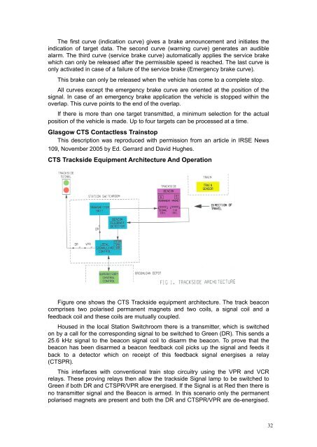
The first curve (indication curve) gives a brake announcement <strong>and</strong> initiates theindication of target data. The second curve (warning curve) generates an audiblealarm. The third curve (service brake curve) automatically applies the service brakewhich can o<strong>nl</strong>y be released after the permissible speed is reached. The last curve iso<strong>nl</strong>y activated in case of a failure of the service brake (Emergency brake curve).This brake can o<strong>nl</strong>y be released when the vehicle has come to a complete stop.All curves except the emergency brake curve are oriented at the position of thesignal. In case of an emergency brake application the vehicle is stopped within theoverlap. This curve points to the end of the overlap.If there is more than one target transmitted, a minimum selection for the actualposition of the vehicle is made. Up to four targets can be processed at a time.Glasgow CTS Contactless TrainstopThis description was reproduced with permission from an article in IRSE News109, November 2005 by Ed. Gerrard <strong>and</strong> David Hughes.CTS Trackside Equipment Architecture And OperationFigure one shows the CTS Trackside equipment architecture. The track beaconcomprises two polarised permanent magnets <strong>and</strong> two coils, a signal coil <strong>and</strong> afeedback coil <strong>and</strong> these coils are mutually coupled.Housed in the local Station Switchroom there is a transmitter, which is switchedon by a call for the corresponding signal to be switched to Green (DR). This sends a25.6 kHz signal to the beacon signal coil to disarm the beacon. To prove that thebeacon has been disarmed a beacon feedback coil picks up the signal <strong>and</strong> feeds itback to a detector which on receipt of this feedback signal energises a relay(CTSPR).This interfaces with conventional train stop circuitry using the VPR <strong>and</strong> VCRrelays. These proving relays then allow the trackside Signal lamp to be switched toGreen if both DR <strong>and</strong> CTSPR/VPR are energised. If the Signal is at Red then there isno transmitter signal <strong>and</strong> the Beacon is armed. In this scenario o<strong>nl</strong>y the permanentpolarised magnets are present <strong>and</strong> both the DR <strong>and</strong> CTSPR/VPR are de-energised.32