CHAPTER 2 BARRIER WARRANTS
CHAPTER 2 BARRIER WARRANTS
CHAPTER 2 BARRIER WARRANTS

You also want an ePaper? Increase the reach of your titles
YUMPU automatically turns print PDFs into web optimized ePapers that Google loves.
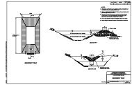
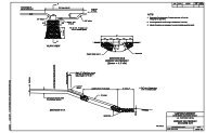
Barrier Warrants ________ November 20052.2 DETERMINE THE NEEDED CLEAR ZONE2.2.1 The Clear ZoneThe area adjacent to the edge of a traveled way available for the safe recovery of anerrant vehicle is known as the clear zone. If adequate clear zone distance is available,there is a reasonable expectation that most drivers of vehicles that leave the roadwaywill have enough room to regain control and return to the pavement without a seriouscrash occurring. The desirable clear zones used for barrier design and evaluationpurposes will not provide sufficient space for all vehicle departures. Some degree of riskis acceptable in the interest of economy. The first step in the warranting process is todetermine the required clear zone because it is normally not necessary to shield hazardslocated outside the clear zone.2.2.2 Clear Zone TableChapter 3 of the AASHTO Roadside Design Guide (RDG) contains charts and tablessuggesting that the needed clear zone is a function of design speed (see the ProjectDevelopment and Design Manual for a discussion of design speed), side slopes andhorizontal curvature: all conditions that may work against the driver’s attempts to regaincontrol of the vehicle. Additional modifications are made for low traffic volume as aneconomic consideration, recognizing that low volumes result in a lower crash probability.The RDG clear zone recommendations provide limited information for low speedconditions. Table 2.1 is an extension of the RDG table to account for speeds below 60km/h (40 mph).Table 2.1 is intended as an aid in determining what potential hazards should beconsidered for barrier warrants. Although it may be useful as suggested minimum clearzones for geometric design, Table 2.1 is not a design standard. Appropriate referencesfor designing slopes are in Chapter 9 of the Project Development and Design Manualand the RDG. In general, slopes should be designed to avoid the need for barriers.Although foreslopes as steep as 1V: 3H are traversable, slopes steeper than 1V: 4H arenot recoverable and are difficult to maintain. They should be considered marginal from asafety perspective. Ideally, foreslopes should be 1V: 4H or flatter. If that objectivecannot be met, a combination (or “barn roof”) slope should be provided, with the topslope 1V: 4H or flatter then breaking to a steeper slope.________________________________________________________________________2-2 Determine the Needed Clear Zone