Manual - Cool Italia GmbH
Manual - Cool Italia GmbH
Manual - Cool Italia GmbH
- No tags were found...

You also want an ePaper? Increase the reach of your titles
YUMPU automatically turns print PDFs into web optimized ePapers that Google loves.
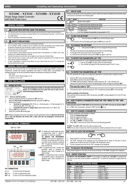
dIXEL Installing and Operating Instructions1592002211“bAL” Serious external alarm Output OFF.12.1 ALARM RELAY STATUSStatus of the instrument XT111C XT111DAS = CL AS= oP AS = CL AS= oPInstrument off 4-6 closed 4-6 closed 20-21 closed 20-21 closedNormal operating 4-6 closed 4-6 open 20-21 closed 20-21 openAlarm present 4-6 open 4-6 closed 20-21 open 20-21 closed12.2 SILENCING BUZZER / ALARM RELAY OUTPUTOnce the alarm signal is detected the buzzer, if present, can be disabled by pressing any key.XT111C/XT111D: the alarm relay status depends on the tbA parameter: with tbA=yES the relay isdisabled by pressing any key, with tbA=no the alarm relay remains enabled as long as the alarm lasts.The display signal remains as long as the alarm condition remains.12.3 ALARM RECOVERYProbe alarms “PFo”, “PFc” start few seconds after the fault in the probe; they automatically stop fewseconds after the probe restarts normal operation. Check connections before replacing the probe.Max. and min. alarms “HA” and “LA” automatically stop as soon as the variable returns to normal values.Alarms “bAL” and “EAL” recover as soon as the digital input is disabled.13. TECHNICAL DATAHousing: self extinguishing ABS.Case: XT110C, XT111C:frontal 32x74 mm; depth 60mm;XT110D, XT111D: 4 DIN modules 70x85 mm; depth 61mm.Mounting: XT110C, XT111C panel mounting in a 71x29 mm panel cut-out.XT110D, XT111D: DIN RAILProtection: IP20.Frontal protection: XT110C, XT111C IP65 with frontal gasket RG-C (optional).Connections: Screw terminal block ≤ 2,5 mm 2 heat-resistant wiring.Power supply: 12Vac/dc, ±10% or: 24Vac/dc ± 10% only for “C” formator 230Vac ± 10%, 50/60Hz or 110Vac, ± 10%, 50/60HzPower absorption: 3VA max.Display: 3 ½ digits, red LEDInputs: according to the order: NTC/PTC or NTC/PTC /Pt100 /Thermocouple J, K, S or 4÷20mA/ 0÷1V /0÷10VRelay outputs: Load relay SPDT 8(3)A, 250VacAlarm: (XT111C/XT111D) relay SPDT 8(3)A, 250VacOther output: buzzer (optional)Kind of action: 1B; Pollution grade: normal, Software class: A;Data storing: on the non-volatile memory (EEPROM);Operating temperature: 0÷60 °C (32÷140°F); Storage temperature: -30÷85 °C (-22÷185°F).Relative humidity: 20÷85% (no condensing)Measuring and regulation range: according to the probe;Controller Accuracy a 25°C: better than ±0,5% of full scale14. CONNECTIONS14.1 XT110C – 12V AC/DC OR 24V AC/DCInput: 4÷20mA0÷1V / 0÷10V14.3 XT111C – 12VAC/DC OR 24VAC/DCLine8(3)A250VPTC / NTC8(3)A250V1 2 3 4 5 6 11 12N.O. ALARMProbe: Pt100= 7 – 9 (8); Thermocouple J, K, S = 7(+); 9(-)24Vac/cd supply: 11-1214.4 XT111C – 230V AC OR 115V ACLine8(3)A250V8(3)A250V1 2 3 4 5 6 7 8N.O. AlarmInput: 4÷20mA0÷1V / 0÷10V7 8 9 107 8 9 10PTC / NTCProbe: Pt100=9–11 (10); Thermocouple J, K, S= 9(+) - 11(-)115Vac supply: 7-814.5 XT110D – 230V AC OR 120V AC OR 24V ACAnalogOutHot-KEY9 10 11 12Input 4÷20mA0÷1V / 0÷10V9 10 11 12Hot-KEYInput: 4÷20mA0÷1V / 0÷10V10 11 12PTCNTC7 8 9 10Hot-KEY8(3)A250VPTC / NTC8(3)A250V7 8 9 10LineLOAD 11 2 3 4 5 6 11 12LineProbe: Pt100= 7 – 9 (8); Thermocouple J, K, S = 7(+); 9(-)24Vac/cd supply: 11-1214.2 XT110C – 230V AC OR 115V ACPTC / NTCHot-KEYProbe: Pt100=11 - 10 (12); Thermocouple J, K, S= 11(+) - 10(-)115Vac supply: 1-2; 24Vac supply: 1-214.6 XT111D – 230V AC OR. 120V AC OR. 24V ACAnalogOutInput: 4÷20mA0÷1V / 0÷10V10 11 129 10 11 12Input 4÷20mA0÷1V / 0÷10VHot-KEY8(3)A250V8(3)A250V8(3)A250V1 2 3 4 5 6 7 8LinePt100=9 –11 (10); Thermocouple J, K, S = 9(+) - 11(-)115Vac supply: 7-89 10 11 12Hot-KEYLOAD 1AlarmLineProbe: Pt100=11 - 10 (12); Thermocouple J, K, S= 11(+) - 10(-)115Vac supply: 1-2; 24Vac supply: 1-21592002211 XT110-111C-D GB R.1.0 15.12.2004.doc XT110C – XT111C - XT110D – XT111D 3/4
dIXEL Installing and Operating Instructions159200221115. DEFAULT SETTING VALUESCOD Name Range °C/°F LevSet Set point LS1÷US1 0/32 -Hy1 Differential -Full Sc./ Full Sc. -1/-2 Pr1LS1 Minimum set point Down Sc./ Set min Pr2US1 Maximum set point Set/ Full Sc. max Pr2S1C Action type output in= Inverse; dir=direct in Pr2Ac Anti-short cycle delay: 0÷250 sec 0 Pr2on Minimum time a stage stays switched ON 0÷250 sec 0 Pr2ono Minimum time between 2 following switching ON 0÷120 min 0 Pr2of the same loadALC Alarm configuration rE=relat.; Ab= absolute rE Pr2ALL Minumum alarm (ALC=rE)0 ÷ |Start Sc.-Set| 10.0/ 20 Pr2(ALC=Ab)Start Sc.÷ ALuALU Maximum alarm (ALC=rE)0 ÷ |Full Sc.-Set|. 10.0/ 20 Pr2(ALC=Ab)ALL÷ Full ScaleALH Alarm recovery differential 0÷Full scale 2.0/4 Pr2ALd Alarm delay 0÷999 min 15 Pr2dAO Alarm delay at start up 0÷23h 50min 1.3 Pr2So1 Output status with faulty pr. oFF=open on=closed oFF Pr2tbA 1 Alarm relay disabling no; yES yES Pr2AS 1 Alarm relay polarity CL÷oP oP Pr2Lci 2 Start scale with current or voltage input -1999÷1999 various Pr1Uci 2 End scale with current or voltage input -1999÷1999 various Pr1OPb Probe calibration -Full Sc./ Full Sc. 0.0 Pr1rES Resolution in=NO; dE=0,1; cE=0,01 in Pr2UdM Measurement unitPbC Kind of probeP3F 3 rd wire presence(temp.)(current/voltage)°C=°C; °F= °F;0=°C; 1=°F; 2=RH;3=bar; 4=PSI, 5=offPt=Pt100; J=tcJ; c= tck;S=tcS; Ptc=PTC; ntc=NTC; 0-1=0÷1V; 10=0÷10V; cur=0÷20mAno=2 wires;yES=3 wiresvarious Pr1various Pr1Aoc 3 Analog output setting Pb / Er Pb Pr2LAo 3 Lower analog output limit: Down Sc./ Full Sc. 0 Pr2uAo 3 Upper analog output limit: Down Sc./ Full Sc. 0 Pr2SAo 3 Analog output safety with probe fault oFF / on oFF Pr2HES Energy saving differential Down Sc./ Full Sc. 0.0 Pr2i1F Digital input configuration c-H / oFF / AuS / HES / EAL Pr2EAL / bALi1P Digital input polarity cL=closed; oP=open cL Pr2did Alarm delay for dig. input 0÷120m 0 Pr2Adr Serial address 0÷247 1 Pr2OnF oFF function enablingno=not enabled;no Pr2yES=enabledPtb Parameter table Readable only -- Pr2rEL Software release Readable only --- Pr2Pr2 To access the Pr2 Readable only 321 Pr11Only for XT111C/XT111D;2Only for instrument with 4÷20mA or 0÷1V or 0÷10V;3Only for instruments with analog ouputnoPr2Dixell S.p.A. Z.I. Via dell’Industria, 2732010 Pieve d’Alpago (BL) ITALYtel. +39 - 0437 - 98 33 - fax +39 - 0437 - 98 93 13E-mail: dixell@dixell.com - http://www.dixell.com1592002211 XT110-111C-D GB R.1.0 15.12.2004.doc XT110C – XT111C - XT110D – XT111D 4/4