VISION TOUCH THR
VISION TOUCH THR
VISION TOUCH THR
- No tags were found...

Create successful ePaper yourself
Turn your PDF publications into a flip-book with our unique Google optimized e-Paper software.
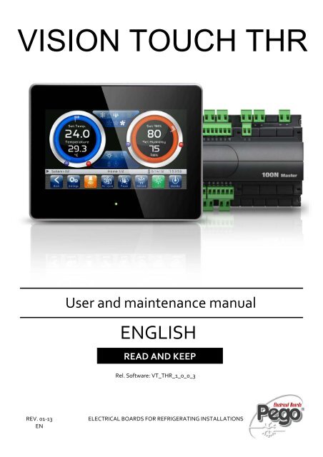
<strong>VISION</strong> <strong>TOUCH</strong> <strong>THR</strong>User and maintenance manualENGLISHREAD AND KEEPRel. Software: VT_<strong>THR</strong>_1_0_0_3REV. 01‐13ENELECTRICAL BOARDS FOR REFRIGERATING INSTALLATIONS
<strong>VISION</strong> <strong>TOUCH</strong> <strong>THR</strong>Thank you for choosing PEGO'S <strong>VISION</strong> <strong>TOUCH</strong> <strong>THR</strong> controller.Reading this manual thoroughly will guide you through proper installation and better use ofthe various features. We therefore recommend keeping this manual near the controller tomake use of it during the device installation, configuration and use.Waste disposal guidelines:The Vision Touch controller consists of glass parts, plastic parts and metal parts.With reference to the Directive 2002/96/EC of the European Parliament and of the Councilof 27 January 2003 and related national legislation, please note that:A. There is the obligation not to dispose of WEEE as urban waste and to performseparate collection of this waste.B. Public or private waste collection facilities foreseen by local laws must be used todispose of the materials. It is also possible to give the device back to the distributorat the end of its life when purchasing a new one.C. This equipment can contain dangerous substances: improper use or incorrect wastedisposal could have negative affects on human health and on the environment.D. the symbol (crossed-out waste bin on wheels) applied to the pack, productand instructions indicates that the appliance was placed on the market after August13, 2005, and must be disposed of separately.E. In case of abusive disposal of electrical and electronic waste, there are sanctionsestablished by local standards in force concerning waste disposal.Pag. 2 USER AND MAINTENANCE MANUAL Rev. 01-13
<strong>VISION</strong> <strong>TOUCH</strong> <strong>THR</strong>CONTENTSINTRODUCTIONPage 5 1.1 General informationPage 6 1.2 Product identification codesPage 7 1.3 Overall dimensionsPage 7 1.4 Identification dataPage 8 1.5 Technical featuresCHAPTER 1INSTALLATIONPage 9 3.1 General rules for the installerPage 9 2.2 Standard equipment for assembly and usePage 10 2.3 Installation and assemblyCHAPTER 2ELECTRICAL CONNECTIONSPage 11 3.1 Console / 100N Master3 power supply and connectionPage 13 3.2 Connection of digital outputs on 100N Master3Page 14 3.3 Connection of digital inputs on 100N Master3Page 15 3.4 Connection of analogue inputs on 100N Master3Page 16 3.5 Connection of analogue outputs on 100N Master3Page 17 3.6 Connection to RS-485 for TeleNET or Modbus- RTUSWITCHING ONPage 18 4.1 CommissioningPage 19 4.2 Switch-on controllerCHAPTER 3CHAPTER 4USER INTERFACEPage 20 5.1 Console functional zonesPage 21 5.2 Main displayPage 21 5.3 Status barPage 22 5.4 Button barPage 24 5.4 GestureCHAPTER 5HOME PAGESPage 27 6.1 Home 1 Temperature/Humidity, I/O status VisualizationPage 32 6.2 Home 1 Temperature/Humidity Set point ModificationPage 33 6.3 Home 2 Loaded program visualization (Recipe)Page 35 6.4 Home 2 Enter Home2 Edit ModePage 36 6.5 Home 2 Home2 Edit Mode with Program StoppedPage 36 6.6 Home 2 Program startPage 37 6.7 Home 2 Load / Save / Export / Import programPage 38 6.8 Home 2 Add / Edit / Cancel program phasesPage 41 6.9 Home 2 Home2 Edit Mode with Program PlayingPage 41 6.10 Home 2 Stop program / Skip phaseCHAPTER 6ACCESS LEVELSPage 42 7.1 Access levels to parameters (User/ installer)Page 42 7.2 Lock screen and User / installer loginCHAPTER 7Pag. 3 USER AND MAINTENANCE MANUAL Rev. 01-13
<strong>VISION</strong> <strong>TOUCH</strong> <strong>THR</strong>PARAMETERSPage 42 8.1 Access to the “Parameters” menuPage 44 8.2 Description of parameters setting pagePage 45 8.3 Parameters menu items listPage 47 - 8.3.1 Process adjustmentPage 47 - 8.3.2 Defrost cyclesPage 49 - 8.3.3 VentilationPage 50 - 8.3.4 Air changePage 50 - 8.3.5 Automatic air changePage 51 - 8.3.6 RecoveriesPage 51 - 8.3.7 Configure <strong>THR</strong>Page 52 - 8.3.8 Machine protectionPage 53 - 8.3.9 Alarms adjustmentPage 54 - 8.3.10 Cold water managementPage 54 - 8.3.11 Hot water managementPage 55 - 8.3.12 pH probePage 55 - 8.3.13 Piercing probePage 56 - 8.3.14 Probes calibrationPage 56 - 8.3.15 Configuration RS458Page 57 - 8.3.16 LanguagePage 57 - 8.3.17 Date and timePage 58 - 8.3.18 General settingsPage 59 - 8.3.19 SoftwarePage 60 - 8.3.20 InfoPage 60 - 8.3.21 PasswordPage 62 - 8.3.22 Test centrePage 67 - 8.3.23 Configure I/OCHAPTER 8DIAGNOSTICSPage 72 9.1 DiagnosticsPage 75 9.2 Alarms managementPage 76 9.3 Pop-up managementCHAPTER 9OPERATIONCHAPTER 10Page 77 10.1 Cold/hot: preservation of ambient temperaturePage 78 10.2 Humidify/dehumidification: preservation of ambient humidityAPPENDICESPage 79 A.1 EC Declaration of ConformityPage 80 A.2 Waranty termsPag. 4 USER AND MAINTENANCE MANUAL Rev. 01-13
CHAPTER 1 - Introduction<strong>VISION</strong> <strong>TOUCH</strong> <strong>THR</strong>CHAPTER 1: INTRODUCTIONGENERAL INFORMATION1.1DESCRIPTIONThe <strong>VISION</strong> <strong>TOUCH</strong> <strong>THR</strong> controller manages the temperature and humidity inseasoning, storage and industrial process environments.The system consists of the 100N Master3 unit, on which all the electrical connections aremade, and the <strong>VISION</strong> <strong>TOUCH</strong> <strong>THR</strong> control console, equipped with 7'' TFT display withcapacitive touch screen combined with a highly advanced software and a highly userfriendly interface that allows easy use.As a whole, it allows a control of the following features: temperature (hot / cold) andhumidity (humidification/dehumidification), defrosting (electric or hot gas), recoveries,dripping, air exchange either programmed or automatic with energy saving function andwith a reading of external temperature / humidity probes, modular valves hot/cold watermanagement, essence input in automatic programs management, evaporator fans speedadjustment (digital outputs slow / fast or with 0-10V signal), activation of internal airrecirculation for destratification.APPLICATIONS:- Seasoning/drying cells.- Storage cells with or without humidity control.- Climatic cells for humidostatic tests, temperature and climatic cycles.MAIN FEATURES:- 7'' TFT display with high resolution (800x480 WVGA), LED backlighting and capacitivetouch screen.- Front with 3 mm hardened glass with shatterproof safety film.- Devices: USB 2.0, microSD, RS485.- Acoustic signals.- IP65 frontal protection.- High quality design and icons.- Touch screen interface with gestures, for an even more intuitive control.- Clock and calendar (RTC).- Password function.- Multilingual.- Customizable user parameter menu (unused features can be hidden, simplifying themenu).- Contextual help in the parameter configuration menu.- Software updating from microSD or USB.- Alarm history combined with popup warning messages.- Advanced HACCP function with detailed memory of temperature / humidity alarmstriggered.- 20 completely customizable programs can be stored on the device.- Ability to export and import programs and parameters on USB or microSD media.Pag. 5 USER AND MAINTENANCE MANUAL Rev. 01-13
<strong>VISION</strong> <strong>TOUCH</strong> <strong>THR</strong>- Automatic management of 21 phases for each program.- Manual or automatic functioning with execution of the selected program.- Ability to force a manual skipping phase during the execution of a program.- Ability to set the execution modality at the end of an automatic program such as:preservation/ cyclical / standby (this last one with the ability to enable an end programwarning).- Diagram of the program in execution with progress display (completed phases, phasesin progress and phases yet to be executed) and a representation of the set values andof all the remaining times.- Temperature adjustment range: -45°C/+99°C; humidity adjustment range: 0-100 R.H.%- Possibility of excluding heat and humidity for managing cell-only storage with theactivation of the defrost cycles.- Dehumidification program with cold / hot / indipendent free voltage contact.- Features managed: temperature (hot / cold) and humidity(humidification/dehumidification), defrosting (electric or hot gas), recoveries, dripping,air exchange either programmed or automatic with energy saving function and with areading of external temperature / humidity probes, modular valves hot/cold watermanagement, essence input in automatic programs management, evaporator fansspeed adjustment (digital outputs slow / fast or with 0-10V signal), activation of internalair recirculation for destratification.- "Test center" mode to check, in a simple and intuitive way, all the digital and analogicalinputs/outputs.- RS485 serial connection with TeleNET or Modbus protocol which can be selected inthe parameters.1.2PRODUCT IDENTIFICATION CODES200VT100<strong>THR</strong>1 <strong>TOUCH</strong> electronic control for temperature andhumidity adjustment complete with all the seasoningfunctions. It has a stylish 7'' TFT display withcapacitive touch screen combined with a highlyadvanced software and a highly user friendly interfacethat allows for easy use.5 m telephone cord included. 2 NTC probes (1x1.5 m+ 1x3 m) included. Humidity probe is separate.Pag. 6 USER AND MAINTENANCE MANUAL Rev. 01-13
<strong>VISION</strong> <strong>TOUCH</strong> <strong>THR</strong>OVERALL DIMENSIONS1.3Dimensions in mm.<strong>VISION</strong> <strong>TOUCH</strong> <strong>THR</strong>100N MASTER3IDENTIFICATION DATAThe device described in this manual has, on the side of 100N MASTER3 and on the backof the <strong>VISION</strong> <strong>TOUCH</strong> <strong>THR</strong> console, a plate bearing its identification data:• Name of Manufacturer• Description of device• Serial number of device• Date of manufacture1.4Pag. 7 USER AND MAINTENANCE MANUAL Rev. 01-13
<strong>VISION</strong> <strong>TOUCH</strong> <strong>THR</strong>1.5TECHNICAL FEATURESPower supplyVoltageMax power consumption (electronic controller only)Climatic conditionsOperating temperatureStorage temperatureRelative ambient humidity110 - 230 V~ ± 10% 50Hz / 60Hz~ 15 VA-5 ÷ +50°C-10 ÷ +70°CLess than 90% RHGeneral featuresType of connectable probes (temperature) NTC 10K 1%Resolution (ambient temperature)0,1 °C.Precision of probe detection (ambient temperature) ± 0,5 °CReading range -45 ÷ +99 °CHumidity probePrecision of humidity probe detectionRange of humidity probe detectionanalogue input 4-20 mAsee humidity probe features0-99 rH%Output featuresDescription Relay installed Features of output board Notesoutput 3-4(30A AC1 relay)n°11 outputs from 5 to26 (see connectionsdiagram)Dimensional featuresDimensions 100 MASTERDimensions <strong>VISION</strong> <strong>TOUCH</strong> <strong>THR</strong>Insulation and mechanical propertiesDegree of protection of displayMaterial of box10A 250V~ (AC3)(100000 cycles)(16A AC1 relay) 16A 250V~ (AC1)(2HP)121,50mm x 71mm x 175mm (HxDxL)151mm x 44mm x 191mm (HxPxL)IP65Self-extinguishing ABSAll the outputs arevoltage-freecontactsPag. 8 USER AND MAINTENANCE MANUAL Rev. 01-13
<strong>VISION</strong> <strong>TOUCH</strong> <strong>THR</strong>CHAPTER 2: INSTALLATIONGENERAL RULES FOR THE INSTALLER2.11. If the program is used in applications with the risk of harming persons, machines ormaterials, it must be coupled with auxiliary alarm devices;2. The programmer must NOT be installed in environments with dangerous atmospheres(flammable or explosive); it can only be connected to elements which operate in thisatmosphere by means of appropriate and suitable types of interface compliant with safetystandards in force;3. Install the appliance in places which respect the degree of protection;4. Avoid using multi-pole cables with conductors connected toinductive and power conductors and signal conductors like probes and digital inputs;5. Avoid housing power cables in the same conduits as signal cables (probes, digital oranalogue inputs, communication cables)6. Minimize the length of the connecting cables to prevent these from coiling up andadversely affecting the electronics through induction;7. All the conductors of the cables must be of an appropriate size to withstand the requiredload;8. Place a general protection fuse upstream the electronic controller;9. Provide a two-phase disconnecting switch compliant with foreseen safety requirements(CE marked) to shut off the power supply upstream the controller.The switch must be placed in the immediate vicinity of the regulator and must be easilyreachable by the operator.10. Should the length of the probes need to be extended, it is necessary to use conductorswith an appropriate cross-section and however no less than 1 mm². Extension orshortening of the probes may alter the factory settings; use an external thermometer,therefore, for testing and calibration.11. When using the console at low temperatures there could be a visible slow down in theresponse from the display; this can be considered normal.STANDARD EQUIPMENT FOR ASSEMBLY AND USE2.2The <strong>VISION</strong> <strong>TOUCH</strong> <strong>THR</strong> electronic controller is provided with the following for assemblyand use:• 2 temperature probes;• 1 plug telephone cable (5m);• 1 user manual;• 1 Vision Touch <strong>THR</strong> (200V<strong>TOUCH</strong><strong>THR</strong>) console;• 4 media for Vision Touch console;• N° 1 100N MASTER3 (200100NMSTH3);Pag. 9 USER AND MAINTENANCE MANUAL Rev. 01-13
<strong>VISION</strong> <strong>TOUCH</strong> <strong>THR</strong>ANALOGUE INPUT CONNECTION ON 100N MASTER33.4POSSIBLE CONFIGURATIONSANALOGUE INPUTS AI1÷ AI5Access menu:Parameters >Configure I/O >Analogueinputs0 = Disabled1 = Ambient temperature (NTC)2 = Evaporator temperature (NTC)3 = Ambient humidity probe (4-20mA)4 = Hot water temperature (NTC)5 = Cold water temperature (NTC)6 = External temperature (NTC)7 = External humidity (4-20mA)8 = pH probe (4-20mA)9 = Piercing probe (NTC)The selection of the desired function for eachanalogue input is done by the configuration of thededicated parameter in the “ Parameters > Configure I/ O > analogue inputs” menu combined with thecorrect setting of the Hardware configuration jumperson the 100N-Master3 under the removable front cover(see the side image).In particular, the configuration is as follows:For NTC probes : J*1=1-2, J*2=2-3, J*3=openForr 4-20mA probes : J*1=2-3, J*2=1-2, J*3=open*= number analogue inputPINTERMINALS27 RH28 V+2930313233343536DESCRIPT.TERMINALSTYPE OFSIGNAL4-20mAANALOGUEOUTPUTAI1DEFAULT SETTINGSANALOGUE OUTPUTS3 = Ambient humidityprobeNTC AI2 1 = Ambient temp.NTC AI3 2 = Evaporator temp.NTC AI4 0 = DisabledNTC AI5 0 = DisabledDEFAULT SETTINGSBRIDGES ON 100N-MASTER3J11=2-3J12=1-2J13= openJ21=1-2J22=2-3J13= openJ31=1-2J32=2-3J33= openJ41=1-2J42=2-3J43= openJ51=1-2J52=2-3J53= openPag. 15 USER AND MAINTENANCE MANUAL Rev. 01-13
<strong>VISION</strong> <strong>TOUCH</strong> <strong>THR</strong>3.5ANALOGUE OUTPUT CONNECTION ON 100N MASTER3POSSIBLE CONFIGURATIONSANALOGUE OUTPUTS AO1÷ AO3Access menu:Parameters >Configure I/O >analogueoutputs0 = Disabled1 = Cold water adjustment2 = Hot water adjustment3 = Speed of the evaporator fansPINTERMINALS41 Ref.44 Gnd42 Ref.44 Gnd43 Ref.44 GndDESCRIPT.TERMINALSTYPE OFSIGNALANALOGUEOUTPUTDEFAULT SETTINGSANALOGUE OUTPUTS0-10V AO1 2=Hot water adjustment0-10V AO2 1=Cold water adjustment0-10V AO3 3=Speed of the evaporator fansPag. 16 USER AND MAINTENANCE MANUAL Rev. 01-13
<strong>VISION</strong> <strong>TOUCH</strong> <strong>THR</strong>CONNECTION TO RS-485 FOR TELENET OR MODBUS-RTU3.6Connect the earth to the GNDterminal of M3 in the console(functional earth). This connectionhelps to limit the effects of theelectromagnetic noise on thecontrol system. The groundconnection must be made in amanner consistent with applicableregulations.Connect the terminal (A) of M3 inthe console to signal A of theModbus line and the terminal (B)of M3 in the console to signal B ofthe Modbus line. Connect thebraid of the shielded cable to theterminal (GND) of M3 in theconsole. Use twisted cablesuitable for the transmission ofRS485 signals with minimumsection of 0.5 mm2 (e.g. Belden8762 cable). Avoid coupling withpower cables.1) Example of connection between the console and the Modbus line:It is recommended to connect a resistance equal to 120Ω between A and B at thebeginning and end of the line in case of communication problems.For a correct functioning the Master has to have a RS485 polarized.Pag. 17 USER AND MAINTENANCE MANUAL Rev. 01-13
<strong>VISION</strong> <strong>TOUCH</strong> <strong>THR</strong>CHAPTER 4: SWITCHING ON4.1COMMISSIONINGWhen the controller is switched on for the first time, the "Language Selection" and "timeand date setting" pages of the system are displayed to facilitate the user in starting up thecontroller. These settings can even be modified further on by means of the "Language"and "Date and time" items within the "Parameters" menu.Set thelanguage bypressing thesebuttons.Confirm thesettings bypressing theconfirmationbuttonSet the dateand time byscrolling yourfinger over thedigits from thetopdownwardsConfirm thesettings bypressing theconfirmationbuttonPag. 18 USER AND MAINTENANCE MANUAL Rev. 01-13
<strong>VISION</strong> <strong>TOUCH</strong> <strong>THR</strong>SWITCH-ON CONTROL4.2Every time the controller is switched on, an information pop-up is displayed with thestarting date and time, requesting the user to acquire the information by pressing "OK".This allows to verify the return from an electrical blackout.Controllerstarting dateand timeInformationacquisitionbuttonThe start-up event is also memorized inside the "alarms" menu to make it possible to verifythis information over time.Accensione strumentoInizio: 18-12-2012 13:45:24Pag. 19 USER AND MAINTENANCE MANUAL Rev. 01-13
<strong>VISION</strong> <strong>TOUCH</strong> <strong>THR</strong>CHAPTER 5: USER INTERFACEThis section illustrates the features and instructions for using the display, the lightindicators and the buttons making up the user interface of the <strong>VISION</strong> <strong>TOUCH</strong> <strong>THR</strong>, andtherefore represent an essential requirement to correctly program and configure thecontroller.5.1CONSOLE FUNCTIONAL ZONESThe display is divided into 3 main parts:• Main display: interactively displays the various home pages and menu items.• Status bar: it is divided into 3 parts and displays the following data:- on the left: running status and name of program in progress.- in the middle: description of current visualization of main display.- on the right: current date/time, presence of USB key, or access as installer• Button bar: views the main operating buttons and their status.At the bottom in the middle there are two LEDs:Green LED: Flashing = controller in stand-by / On fixed = Controller poweredRed LED: Flashing = controller in AlarmMain displayStatus barButton barIndicatorLEDsPag. 20 USER AND MAINTENANCE MANUAL Rev. 01-13
<strong>VISION</strong> <strong>TOUCH</strong> <strong>THR</strong>MAIN DISPLAY5.2The section of the main display views the work and setting pages based on the position(for example Home, Configuration, phase). A detailed description of the various pages willbe made further on in this manual.STATUS BAR5.3The Status Bar is in the lower part of the display (above the Button Bar, if applicable)and displays some important information relating to the status of the device, such as thename of the recipe in progress and the description of the currently displayed page. It isalways present except when, in some rare cases, it is temporarily hidden to fully exploit thedisplay.Status (running or stopped •)and name ofprogram inprogress.Description ofcurrent page, itsposition andtotal n. of pagespresent.USB PresenceIcon, SDpresence Icon,User logged asinstaller.Current dateand time.Pag. 21 USER AND MAINTENANCE MANUAL Rev. 01-13
<strong>VISION</strong> <strong>TOUCH</strong> <strong>THR</strong>5.4BUTTON BARThe Button Bar is at the bottom of the display and views the main operating buttons andtheir status. It is always present except when, in some rare cases, it is temporarily hiddento fully exploit the display.The buttons can have different shapes but always include an icon, a description and thecolour identifying the status.In particular, the colour code of the buttons is the following:BLUE:Button which can be enabledGREY:Button not active (Disabled)GREEN:Button function activated or Confirmation buttonYELLOW:Cancel buttonRED:Alarm triggered indication or File elimination buttonORANGE:Indication of alarm no longer triggered but yet to be acquiredSome buttons have delayed activation to avoid unintentional commands (see standby forexample). When pressed the progressive colour change is viewed until the function isactivated.Pag. 22 USER AND MAINTENANCE MANUAL Rev. 01-13
<strong>VISION</strong> <strong>TOUCH</strong> <strong>THR</strong>Description of buttons in Button Bar:BackBACK:Inside a menu or level: Go back to previous level or menu.In a HOME page: Go back to the previous Home page.If held for longer than 3 seconds: Go back to HOME1 pagePARAMETERS: Enter the parameter setting menuSettingsAlarmALARMS: Enter the alarm log menuRed: Alarm triggeredOrange: Alarm over but yet to be acquiredBlue: No Alarm triggered or to be acquiredIf the alarm log menu contains only items already acquired (shown in black) a waste bin willappear inside this button indicating the possibility of cancelling the entire log.Air cyclePauseDefrostLightStandbyMANUAL AIR RENEWAL: Activates a manual air renewal or deactivates an automatic ormanual one in progress. (delayed start)Green: Air renewal activeBlue: Air renewal not activeMANUAL RECOVERY: Activates a manual recovery or deactivates an automatic or manualone in progress. (delayed start)Green: Recovery activeBlue: Recovery not activeMANUAL DEFROST: Activates a manual defrost or deactivates an automatic or manual onein progress. (delayed start)Green: Defrost output activeBlue: Defrost output not activeMANUAL CELL LIGHT BUTTON: Manually activates/deactivates the cell light.Green: Light activeBlue: Light not activeFlashing light icon: Indicates the forced activation of the light from the digital input of themicro gate open. With the open gate digital input, the manual cell light, defrost, recovery andair cycle buttons are deactivated.STANDBY BUTTON: Activates/deactivates the standby status (delayed start)Green: Standby active (System OFF)Blue: Standby not active (System ON)During standby, the program in progress keeps the count of the remaining time.Pag. 23 USER AND MAINTENANCE MANUAL Rev. 01-13
<strong>VISION</strong> <strong>TOUCH</strong> <strong>THR</strong>5.5GESTUREThe Vision Touch, aside from normal pressing of keys, on some pages supports gestureswhich allow the user a more natural and therefore simpler interaction.Change Home Page: On one Home page, move your finger to the left or to the right topass from one Home page to the next one or to the previous one.Note: it is also possible to move inside the Home pages by pressing the Back button.The middle of the status bar has the description of the page currently displayed, itsposition and the total number of pages displayable (for example 1/2 means you areviewing page 1 of a total number of 2 displayable pages).Description ofcurrent page, itsposition andtotal n. of pagespresent.Change Page of a table or parameter list: Move your finger up or down to pass to thenext or previous data page.The middle of the status bar has the description of the page currently displayed, itsposition and the total number of pages displayableDescription ofcurrent page,its positionand total n. ofpages present.Pag. 24 USER AND MAINTENANCE MANUAL Rev. 01-13
<strong>VISION</strong> <strong>TOUCH</strong> <strong>THR</strong>Change parameters with roll selection: Move your finger up or down by one roll tochange its value. (Suggestion: move your finger starting from the outside of the roll andpass through it completely).If the value you are trying to set is not allowed and is not included in the range of thevariables, the background of the roll will turn red for an instant indicating that the action isnot allowed.Changing parameters with a switch: Move your finger to the right or to the left toactivate or deactivate a switch.Selection of parameters with Flags: press the flag to change the status or to select oneof the possible options.Pag. 25 USER AND MAINTENANCE MANUAL Rev. 01-13
<strong>VISION</strong> <strong>TOUCH</strong> <strong>THR</strong>"Edit" mode in Home 1 and 2 pages: When you are on one of the Home pages, touchthe screen at a point which is not a button for more than three straight seconds to enteredit mode of the page itself. To exit this mode, press the "Back" button or wait for theautomatic exit after one minute of inactivity.Edit Home 1 Page, Change Set Point with Wheel: Once you have entered edit mode onHome 1, it is possible to change the humidity and temperature Set Points currently in use.The variations are temporary and do not alter the preset program. Turn clockwise toincrease or anti-clockwise to decrease the value of the Wheel of the Set Point to bemodified or else act on the plus or minus buttons. Then confirm the new values bypressing the green confirmation button.Pag. 26 USER AND MAINTENANCE MANUAL Rev. 01-13
<strong>VISION</strong> <strong>TOUCH</strong> <strong>THR</strong>CHAPTER 6: HOME PAGESThe "Home" pages are the main interface of the controller from whence it is possible toaccess the mostly used features. They are divided as follows:HOME 1Display and modification of temperature andhumidity set points, display of I/O status andsecondary or information variables.HOME 2Complete management of programs (Recipes):Visualization, creation, editing, cancellation, loading,export, import.HOME 1 – Temperature / Humidity, I/O status management6.1“Home1” allows to view and modify Temperature and Humidity settings, to visualize thedigital input/output statuses, additional adjustments and coupled probes, additional inputssuch as pH and the status of the recipe being run.When in visualization, it is divided into 3 main sections:• Temperature adjustment dial• Humidity adjustment dial• Multifunction data visualization dialTemperatureAdjustment dialMultifunction Display dati datavisualization multifunzione dialHumidityAdjustment dialPag. 27 USER AND MAINTENANCE MANUAL Rev. 01-13
<strong>VISION</strong> <strong>TOUCH</strong> <strong>THR</strong>Temperature adjustment dial: Displays all that regards temperature adjustment, inparticular:• The temperature set point (can be modified by pressing the dial for 3 sec)• Adjustment probe temperature measurement• The status of the call (Cold/Hot/No call)• The Minimum Temperature alarm set on At1 which can be reached on "Parameters >Alarm adjustments > At1 Minimum temperature alarm" and indicated with the icon• The Maximum Temperature alarm set on At2 which can be reached on "Parameters >Alarm adjustments > At2 Maximum temperature alarm" and indicated with the iconTemperature valueBar-graphTemperature Set-PointBar-graphTemperatureSet PointNotice of Set-point changedwith program in progressMinimum temperaturealarmCHANGEDStatus of call:Cold CallHot CallNo CallAdjustment probetemperatureMaximum temperaturealarmHumidity adjustment dial: Displays all that regards humidity adjustment, in particular:• The humidity set point (can be modified by pressing the dial for 3 sec)• Adjustment probe humidity measurement• The status of the call (Humidify/Dehumidify/No call)• The Minimum Humidity alarm set on AU1 which can be reached on "Parameters >Alarm adjustments > AU1 Minimum humidity alarm" and indicated with the icon• The Maximum Humidity alarm set on AU2 which can be reached on "Parameters >Alarm adjustment >AU2 Maximum humidity alarm" and indicated with the iconStatus of the call:Dehumidify CallHumidify CallNo CallHumiditySet PointMinimum HumidityALARMCHANGEDHumidity Set PointBar-graphHumidity valueBar-graphAdjustment probehumidity measurementNotice of Set-point changedwith program in progressMaximum HumidityalarmPag. 28 USER AND MAINTENANCE MANUAL Rev. 01-13
<strong>VISION</strong> <strong>TOUCH</strong> <strong>THR</strong>Multifunction data visualization dial: it consists of two parts which, when touched,cyclically alternate the data displayed. The following are the various screens and theirrelated meanings. Note: Some data is only viewed if the relative function is enabled in theconfiguration parameters.DIGITAL OUTPUT STATUS(Always visible)ColdFlashing= StandbyHotHumidifyDehumidifyseparateDehumidifyfor heatDehumidifyfor coldFanslow speedFlashing= StandbyFanshigh speedFlashing= StandbyFanswith 0-10V output0-10VLightFlashing= micro gateRecoveryDrippingDefrostFlashing= DrippingEssenceDIGITAL INPUT STATUS(Always visible)Air changeAir changeautomaticDisable heatremotelyDisable humidityremotelyStandbyremotelyStandbyHumidifier alarmFans protectionGeneric Warning 1Micro gate Generic Warning 2Generic alarmremotelyGeneric Warning 3CompressorprotectionPROGRAM IN PROGRESS COUNTDOWN(visible while the program is running)This dial is only displayed while the program is running. Itindicates the name and the time remaining to the end of theprogram in progress.Pag. 29 USER AND MAINTENANCE MANUAL Rev. 01-13
<strong>VISION</strong> <strong>TOUCH</strong> <strong>THR</strong>STAGE IN PROGRESS COUNTDOWN(visible while the program is running)This dial is only displayed while the program is running. Itindicates the name and the time remaining to the end of thestage in progress.EVAPORATOR TEMP. PROBEMEASUREMENT(visible if enabled)This dial is only viewed if the variable “Parameters >Defrosts > dE Evaporator probe enabled = 1” and if therelated analogue input is set.Ph PROBE MEASUREMENT(visible if enabled)This dial is only viewed if the variable “Parameters > pHprobe > EpH measurement enabling = 1” and if the relatedanalogue input is set.HOT WATER TEMP. PROBEMEASUREMENT(visible if enabled)This dial is only viewed if the variable “Parameters > Hotwater management > EHv Hot water management enabling= 1” and if the related analogue input is set.COLD WATER TEMP. PROBEMEASUREMENT(visible if enabled)This dial is only viewed if the variable “Parameters > Coldwater management > EHv Cold water managementenabling = 1” and if the related analogue input is set.EXTERNAL TEMP. PROBEMEASUREMENT(visible if enabled)This dial is only viewed if the variable “Parameters >Automatic air change> EEs Energy saving enabling = 1”and if the related analogue input is set.EXTERNAL HUMIDITY PROBEMEASUREMENT(visible if enabled)This dial is only viewed if the variable “Parameters >Automatic air change> EEs Energy saving enabling = 1”and if the related analogue input is set.Pag. 30 USER AND MAINTENANCE MANUAL Rev. 01-13
<strong>VISION</strong> <strong>TOUCH</strong> <strong>THR</strong>PIERCING PROBE MEASUREMENT(visible if enabled)This dial is only displayed if the variable “Parameters >Piercing probe > EnS Pin probe enabled = 1” and if therelated analogue input is set.Pag. 31 USER AND MAINTENANCE MANUAL Rev. 01-13
<strong>VISION</strong> <strong>TOUCH</strong> <strong>THR</strong>6.2HOME 1 – Temperature/Humidity Set point Modification"Set point edit" mode on Home 1 page:Touch one of the adjustment dials on the screen (Temperature or humidity) for more thanthree consecutive seconds.Once you have entered the edit mode, it is possible to change the humidity andtemperature Set Points currently in use by rotating the Wheel clockwise to increase or anticlockwiseto decrease the value of the Set Point to be modified. Otherwise you can pressthe plus and minus buttons. Then confirm the new values by pressing the green "Confirm"button or by pressing "Cancel" to go back to the display screen.To exit this mode, you can also press the "Back" button or wait for the automatic exit afterone minute of inactivity.Pag. 32 USER AND MAINTENANCE MANUAL Rev. 01-13
<strong>VISION</strong> <strong>TOUCH</strong> <strong>THR</strong>HOME 2 – Loaded program visualisation (Recipe)6.3“Home2” allows complete management of the programs (Recipes): status progressdisplay, creation, modification, cancellation, loading from archive and export/import fromUSB or SD.When in visualization, it is divided into 2 main sections:• Program summarizing bar and status of adjustment variables• Program phases and their state of execution (Time line)Program summarizing barand status of adjustmentvariablesProgram phases and theirstate of execution(Time line)Program summarizing bar and status of adjustment variables: Views the summary ofthe loaded program and the current temperature and humidity values, in particular:• Name of loaded program and Time remaining to the end of program; the latter ispresent if the program is running.• Type of operation at end of program: ( At end of program preserve settings of lastphase carried out / At end of program repeat phases - cyclical / At end ofprogram switch to standby)• Current temperature and humility values and statuses of calls (see dial colours).Timeremaining toend ofprogramName ofloadedprogramType ofoperation at endof programControl probetemperaturemeasurementControl probehumiditymeasurementPag. 33 USER AND MAINTENANCE MANUAL Rev. 01-13
<strong>VISION</strong> <strong>TOUCH</strong> <strong>THR</strong>Program phases and their state of execution (Time line): Views the phases of aprogram and all related data, in particular:• Key of set values in phases• Phases already carried out (grey background and green check on time remaining; theyappear if the program is running)• Phase in execution (background with grey side bands and green time remaining; theyappear if the program is running)• Phases yet to be carried out (black background)Key of setvalues inphasesPhasesalreadycarried outPhase inexecutionPhases tobe carriedoutButtons tomove betweenphase pagesThe columns have a summary of the specific settings for each individual phase and, if theprogram is running, they display the time remaining for the phase in progress (if the phasehas already been carried out, a green check appears in the time remaining)Phase N.d p e aPhase options: d=drippingp=pause (recovery)Temperature setting in phase/ e= essence/ a= air changeTime phase periodTempo durata fasePhase Status or Time remaining to end of phase:= Time remaining to end of phase= Phase executed and completed by time= Phase executed and completed by the needle probe (ifenabled)Pag. 34 USER AND MAINTENANCE MANUAL Rev. 01-13
<strong>VISION</strong> <strong>TOUCH</strong> <strong>THR</strong>HOME 2 –Enter Home2 Edit Mode6.4By entering edit mode in Home2 it is possible to perform the following features:With Program stopped (not running)• Start the program currently loaded• Start the program manager (save/load/import/export)• Edit the program currently loadedWith Program running• Stop the program in progress• Skip the phase being run• View the program currently loaded in detail"Program edit" mode on Home2 page:Touch any part of the Home2 screen (on the program summary bar or on the phase list)for more than three consecutive seconds.To exit this mode, you can also press the "Back" button or wait for the automatic exit afterone minute of inactivity.Pag. 35 USER AND MAINTENANCE MANUAL Rev. 01-13
<strong>VISION</strong> <strong>TOUCH</strong> <strong>THR</strong>6.5Home 2 – Home2 Edit Mode with Program StoppedWith Program stopped (not running) and entering edit mode in Home2, the followingscreen appears:Change the genericsettings of the loadedprogramProgram manager: save,load, import, export.Start programcurrently loadedAdd a new phaseof the loadedprogram.21 manageablephases (from 0 to20)Exit edit mode.Change the settings ofthe phases of the loadedprogramCancel the phasesof the loadedprogram6.6HOME 2 – Start programThe button appears with the program stopped and entering edit mode in Home2.StartStart program:Start running the loaded program.When pressed the program starts running and the button changes to Stop.The graph views the progress of the phases.Pag. 36 USER AND MAINTENANCE MANUAL Rev. 01-13
<strong>VISION</strong> <strong>TOUCH</strong> <strong>THR</strong>6.7HOME 2 – Load/Save/Export/Import programThe button appears with the program stopped and entering edit mode in Home2.ManagerProgram manager:When pressed, the management program shown in the following pictureopens up.It saves the currentprogram in the internalmemory of the controlleras.Inside the menu:It imports programsfrom a USB externalmemory unit loadingthem in the internalmemory of the controllerInside the menu:= Import from USBN.B. Make sure that the USBmemory unit is insertedIt imports programsfrom an SD externalmemory unit loadingthem in the internalmemory of thecontrollerInside the menu:= Import from SDN.B. Make sure that the SDmemory unit is insertedLoad the program to becarried out from theinternal memory of thecontroller.Inside the menu:= Load= CancelExport programs frominternal memory of thecontroller to the externalUSB memory unitInside the menu:= Export to USBN.B. Make sure that the USBmemory unit is insertedIt exports programsfrom internal memory ofthe controller to theexternal SD memoryunitInside the menu:= Export to SDN.B. Make sure that the SDmemory unit is insertedPag. 37 USER AND MAINTENANCE MANUAL Rev. 01-13
<strong>VISION</strong> <strong>TOUCH</strong> <strong>THR</strong>HOME 2 – Add /Edit/ Cancel program phases6.8The buttons below appear with the program stopped (not running) and entering the editmode in Home2.Add a new phase of the loaded program.21 manageable phases (from 0 to 20)New phaseChanges the generic settings of the loaded program or the settings ofthe various phases.Cancel the phases of the loaded programBy pressing the button on the left of the program name at the top of the summarybar, you enter the following program options configuration page.At program endpreservation:At the end of the program thetemperature and humiditysettings of the last phasecarried out are preserved.At program endphases loop:At the end of the lastphase the program goesback to the initial phase0 creating an infinitephase loop.Notice (popup) at programend:The user is informed of the end of aprogram by means of a notice Popup.(Press OK to acquire the message)At program endstandby:At the end of the program thecontroller switches to standby.Switch on relay at program end:A specific relay is activated when the program end notice pop-up ispresent. By pressing OK in the Pop-up, the relay de-energisesand the pop-up closes.Pag. 38 USER AND MAINTENANCE MANUAL Rev. 01-13
<strong>VISION</strong> <strong>TOUCH</strong> <strong>THR</strong>By pressing the button at the top left of each column of the phases you enter agroup of three option configuration pages relative to the selected phase.Phase N.Change the settings ofthe phases of the loadedprogramPhase configuration page 1/3:Selected phase N.Ventilation, Recovery, drippingoption lightsConfirm and cancelmodificationsbuttonsPhaseperiod(hh:mm)Temperature Setpoint (°C)Humidity Setpoint (%RH)Buttons for moving betweenconfiguration pagesPag. 39 USER AND MAINTENANCE MANUAL Rev. 01-13
<strong>VISION</strong> <strong>TOUCH</strong> <strong>THR</strong>Phase configuration page 2/3:Recovery:Enables the recoveryfunction (pause intemperature andhumidity managementof the selected phase).The Recoveries aremanaged with the Prand dr parameters inthe specific menupresent in theparameters.Phase configuration page 3/3:Evaporator fan speed selection inselected phase.If the 0-10V output is selected for fan speedregulation (parameter EFa=1 in the Ventilationmenu present in the parameters) there is aspeed selection roll instead of these two flags(20-100%)Dripping:(Only in Phase 0)Enables the drippingfunction in which humiditymanagement is disabled.It is also possible to selecttemperature managementonly in hot or in hot andcold.Piercingprobe:Enables thepiercing probefunction.Determines thetemperature setpointthat makesthe stage inprogress end.Essence:Determines theEssence input in thephase if enabled.Essence period:Determines the duration of theEssence input in the phase. (It mustbe less than the Phase period)Air change:Enables the recovery function(pause in temperature andhumidity management of theselected phase.Pag. 40 USER AND MAINTENANCE MANUAL Rev. 01-13
<strong>VISION</strong> <strong>TOUCH</strong> <strong>THR</strong>6.9Home 2 – Home2 Edit Mode with Program playingWith Program playing (running) and entering edit mode in Home2, the following screenappears:Views the genericsettings of the programrunning.Skip phase:Skips the phase currently runningpassing on to the next one. Whenthis key is pressed standby isactivated as well.Stop program inprogressExit edit mode.Views the settings of thephases of the programrunning6.10HOME 2 – Stop program / Skip phaseThe button appears with the program playing and entering edit mode in Home2.StopSkipStop program:Stops execution of the program running.When pressed the button switches to Stop.Skip phase:Skips the phase currently running passing on to the next one.When this key is pressed the controller also goes into standby.Pag. 41 USER AND MAINTENANCE MANUAL Rev. 01-13
<strong>VISION</strong> <strong>TOUCH</strong> <strong>THR</strong>CHAPTER 7: ACCESS LEVELSAccess levels to parameters (User/ installer)7.1The controller has two access levels to the parameters and to the functions: “User” and“Installer”. The default setting is User that has a parameter menu that can be customisedby the installer. Installer access is by logging in from the « Parameters > Password >installer login » menu and inserting the assigned password.PASSWORDS SET BY DEFAULT :Installer Password : 100Screen for entering accesspasswordThe user logged in as installer is indicated on the Status bar with an open lock. Logout isperformed automatically after one minute of inactivity or manually from the « Parameters >Password > Installer Logout» menuOpen lock icon: User logged in as installer.Lock screen and User / Installer login7.2If the « Lock screen with password » function is activated, access as an installer or as auser is based on the entered password while the screen unlocks.P ASSWORDS SET BY DEFAULT :User Password : 200Installer Password : 100Locked screen displaypositioned in Button bar.By pressing the Unlock button, you reach the Password entry display tounlock the screen.Pag. 42 USER AND MAINTENANCE MANUAL Rev. 01-13
<strong>VISION</strong> <strong>TOUCH</strong> <strong>THR</strong>CHAPTER 8: PARAMETERS8.1Access to Parameters menuPress the "Parameters" button in the Button Bar to access the control parameters settingmenu.PARAMETERS:Enters the parameter setting menuSettingsProcess regulationDefrostFansAir changeAutomatic air changePause<strong>THR</strong> configureMachine protectionAlarms regulationCold water managementHot water managementpH probePiercing probeProbes calibrationCommunication RS485LanguageDate and timeSoftwareInfoPasswordTest centerI/O configureGeneral settingsEach item of the parameters menu gathers a list of variables specific for the functiondescribed in the menu and in some cases a further submenu.The items present in the main branch are all displayed if you are logged in as "Installer",while the items displayed under "User" depends on the configuration set in "parameters >configure user level menu" visible only if logged in as Installer.Pag. 43 USER AND MAINTENANCE MANUAL Rev. 01-13
<strong>VISION</strong> <strong>TOUCH</strong> <strong>THR</strong>Description of parameter setting pagePress the "Parameters" button in the Button Bar to access the controller parameterssetting menu. Each sub-menu contains the name of the variables that can be set, a briefdescription in the selected language and the currently set value.8.2Variable nameVariable descriptionCurrent valued4d5d6d7Intervallo di sbrinamento ciclicoMassima durata sbrinamentoSetpoint di fine sbrinamentoDurata sgocciolamentodF1 Programmazione orari sbrinamentodF2 Programmazione orari sbrinamentoPress the name of the variable to be set to access the relative modification page.VariablenameDetailed description, indicatingthe range of values that theparameter can take onModifiable parameter value.In the event of incorrectsetting, the error issignalled.Pag. 44 USER AND MAINTENANCE MANUAL Rev. 01-13
<strong>VISION</strong> <strong>TOUCH</strong> <strong>THR</strong>8.3List of parameter menu itemsListed below is the complete list of items displayed in the “Parameters” menu.Name Symbol General description ChapterProcessregulationDefrostsFansGeneral process parameters(differential and neutral area settings)Defrosting, dripping, evaporator presencesettingsFans activation and relative speed settings, 0-10 V outlet setting8.3.18.3.28.3.3Air change Air change time setting (up to 6) 8.3.4Automatic airchangePauseEnergy saving setting(energy saving - outside environment use)Recovery period and duration setting(pause)8.3.58.3.6Configure <strong>THR</strong>MachineprotectionAlarmregulation<strong>THR</strong> mode setting(Humidification/dehumidification management)System protection parameters: compressormanagement, limits for set-points,dehumidification limit time8.3.78.3.8Temperature/humidity alarms adjustment 8.3.9Cold watermanagementHot watermanagementCold water system valve managementparameters (cold call)Hot water system valve managementparameters (hot call)8.3.108.3.11pH probe pH probe enabling and management 8.3.12Piercing probe Piercing probe enabling and management 8.3.13ProbecalibrationCorrection of temperature/humidity probes,hot/cold water temperature, etc. values8.3.14RS485communicationConfiguration of RS485 serial communication 8.3.15Pag. 45 USER AND MAINTENANCE MANUAL Rev. 01-13
<strong>VISION</strong> <strong>TOUCH</strong> <strong>THR</strong>Language Control unit language setting 8.3.16Date and timeDate and time settings (not accessible while aprogram is running)8.3.17General settings Contrast, brightness and sound alarms setting 8.3.18SoftwareInfoPasswordTest centerConfigure I/OManagement of control software reset andupdate, device parameters export/import fromUSB/SD<strong>VISION</strong> <strong>TOUCH</strong> <strong>THR</strong> device information(software version, memory occupied)Management of protection level: user/installeraccess, menu configurationDigital/analogue inputs/outputs test,touchscreen interface operation testConfiguration of functions associated todigital/analogue inputs/outputs8.3.198.3.208.3.218.3.228.3.23Pag. 46 USER AND MAINTENANCE MANUAL Rev. 01-13
<strong>VISION</strong> <strong>TOUCH</strong> <strong>THR</strong>Process regulation8.3.1“Process adjustment” allows setting the differentials and the temperature and humidityneutral area of the <strong>THR</strong>.The “Process adjustment” menu can be accessed from the main Configuration page(“Parameters” Button). The display of this item can be set in the “Password” sub-menu =>“Configure user level menu” and by selecting the “Process adjustment” item (installer loginrequired).Process regulationVARIABLES MEANING VALUES DEFAULTdtCHOT temperature differential with reference to main SET-POINT. It is expressed in absolute value and it defines thetemperature hysteresis for HOT referred to the temperature(dtn+0,2) ÷ 10 °C 2 °CSET-POINT.dtFCOLD temperature differential with reference to main SET-POINT. It is expressed in absolute value and it defines thetemperature hysteresis for COLD referred to the temperatureSET-POINT.(dtn+0,2) ÷ 10 °C 2 °CdtndUUdUddUnNEUTRAL temperature zone with reference to main SET-POINT. Cold and hot are not activated in the neutral zone; itsymmetrically includes both the upper part (hot) and the lowerpart (cold) respect to the temperature SET-POINT.HUMIDIFICATION differential with reference to humidity SET-POINT. It is expressed in absolute value and it defines thehumidification hysteresis referred to the humidity SET-POINT.DEHUMIDIFICATION differential with reference to humiditySET-POINT. It is expressed in absolute value and it defines thedehumidification hysteresis referred to the humidity SET-POINT.NEUTRAL humidity zone with reference to main SET-POINT.Humidification and dehumidification are not activated in theneutral zone; it symmetrically includes both the upper part(humidification) and the lower part (dehumidification) respect tothe temperature SET-POINT.0 °C÷dtn ≤ (dtF-0.2) edtn ≤ (dtC-0.2)(dUn+1) ÷ 10rH%(dUn+1) ÷ 10rH%0 rH%÷dUn ≤ (dUU-1) edUn ≤ (dUd-1)0 °C5 rH%5 rH%0 rH%Defrosts8.3.2Defrosts are managed with the parameters d4, d5, d6, d7, F5 which define their intervals,the maximum duration, the defrost end temperature, dripping and fan stopping. To switchdefrost on manually, just press the “Defrost” button. Defrosting will not be activated if thedefrost end temperature (d6) is set lower than the temperature detected by the evaporatorprobe. Defrosting will end when the defrost end temperature (d6) or the maximum defrostperiod (d5) is reached.The “Defrost cycles” menu can be accessed from the main Configuration page(“Parameters” Button). The display of this item can be set in the “Password” sub-menu =>“Configure user level menu” and by selecting the “Defrosting cycles” item (installer loginrequired).Pag. 47 USER AND MAINTENANCE MANUAL Rev. 01-13
<strong>VISION</strong> <strong>TOUCH</strong> <strong>THR</strong>DefrostVARIABLES MEANING VALUES DEFAULTd4Defrost interval (hours).If d4=ON one must set the cyclic defrosting interval.OFF / 1 ÷ 24 hours OFFd5 Maximum defrost period (minutes) 1 ÷ 60 min 10 minDefrost end Set-point.Defrosting is not carried out if the temperature detected6 thedefrost probe is higher than the value d6-35 ÷ 45 °C 15°C(If the probe is faulty, the frosting is timed)Dripping period (minutes)d7At the end of defrosting, the compressor and fansremain stopped for the set time d7, the defrost icon0 ÷ 10 min 0 minflashes.dF1…dF6Defrost times programmingIt is possible to set up to 6 times for defrost.OFF / 00:00 ÷ 23:59 OFFdE Evaporator probe exclusion0 = probe absent1 = probe present1d1Type of defrostCycle inversion (hot gas) or resistance. With hot gas0 = resistance1 = hot gas (defrostingoutlet off during dripping)2 = hot gas (defrosting 0the compressor output is also activated.outlet on during dripping,to manage bowlresistances)di Smart defrosts.0 = disabled1 = enabled0Intelligent defrosting“Intelligent defrosting” is a special defrosting activation technique aimed at energy savings.It is recommended to use this function in the event of defrosting cycles equally distributedthroughout the day (for example cyclic defrosting).Hot gas defrostSet parameter d1 = 1 for managing cycle inversion defrosting.The compressor relay and the defrosting relay are activated for the entire defrostingphase.If d1 = 2, the defrosting outlet stays active during the dripping stage to manage the bowlresistances.For the correct management of the plant, it will be the responsibility of the installer to usethe defrost output, that must allow the opening of the cycle inversion electrovalve and theclosing of the liquid electrovalve.For the capillary plants (without thermostatic valve) it is sufficient to control the cycleinversion electrovalve using the defrosting relay control.Pag. 48 USER AND MAINTENANCE MANUAL Rev. 01-13
<strong>VISION</strong> <strong>TOUCH</strong> <strong>THR</strong>Ventilation8.3.3The parameters of the Ventilation menu allow to set the management of the fans in thevarious operating modes. The “Ventilation” menu can be accessed from the mainConfiguration page (“Parameters” Button). The display of this item can be set in the“Password” sub-menu => “Configure user level menu” and by selecting the “Ventilation”item (installer login required).FansVARIABLES MEANING VALUES DEFAULTF5F3F4F6F7F8EFaFsFstFan pause after defrost (minutes)Allows to keep the fans stopped for a time F5 after dripping.This time starts counting from the end of dripping. If drippingis not set, at the end of defrost the fans pause immediately.Fan status when cold, hot, humidification anddehumidification are stoppedFan pause during defrostEvaporator fans activation for air circulation.The fans are activated for a time defined by F7 if they werenot switched on for the time F6.If the time of activation coincides with the defrost phase, itwaits for the end of defrost.The fan speed (high/low) is the same as that selected for thephase in progress.Evaporator fans activation period for air circulation.Time fans running for air circulation (F6).Fan speed in seasoning/preservation phase. The value ofthis variable changes based on the setting made in the lastphase of a program carried out.Enables 0-10V output for fan speed controlThe digital outputs high and low fan speed becomes theenable. (Them Turned on if the 0-10V output higher than 0V)Fan speed (percentage) when EFa=1.The value of this variable changes based on the setting madein the last phase of a program carried out.FAN blocking TEMPERATUREThe fans do not switch on if the value of the temperature readby the evaporator probe is higher than the value of thisparameter. The block is deactivated when the evaporatorprobe is disabled or presents an error.0 ÷ 10 min 0 min0 = Fans runningconstantly1 = Fans off if cold,hot, humidificationand dehumidificationoff2 = off with coldactive0 = Fans runningduring defrost1 = Fans not runningduring defrostOFF / 1 ÷ 240 min11OFF0 ÷ 240 sec 10 sec0 = High speed1 = Low speed0 = disabled1 = enabled20 ÷ 100 % 100%-45 ÷ 99 °C +99°CFd Differential for Fst 1…+10°C 2°C00Pag. 49 USER AND MAINTENANCE MANUAL Rev. 01-13
<strong>VISION</strong> <strong>TOUCH</strong> <strong>THR</strong>8.3.4Air changeThe air changes can be enabled with parameter rA. Up to six daily execution times for airchange can be set in parameters from rA1 up to rA6. The duration of the air changeisdefined by parameter drA. During air change, hot, cold, humidity and dehumidification donot activate. It is possible, at any time, toforce an air change with the “Air cycle” button.The “Air change” menu can be accessed from the main Configuration page (“Parameters”Button). The display of this item can be set in the “Password” sub-menu => “Configureuser level menu” and by selecting the “Air change” item (installer login required).Air changeVARIABLES MEANING VALUES DEFAULTdrA Air change period. 1 ÷ 10 min 6rA1Air change time programmingOFF / 00:00 ÷…OFFIt is possible to set up to 6 times for air change.23:59rA68.3.5Automatic air changeThe “Automatic air change” menu can be accessed from the main Configuration page(“Parameters” Button). The display of this item can be set in the “Password” sub-menu =>“Configure user level menu” and by selecting the “Automatic air change” item (installerlogin required).Automatic air changeVARIABLES MEANING VALUES DEFAULTEEs Enable energy saving0 = disabled1 = enabled0dEs Energy saving Sensitivity 0 ÷ 200 % 0tEs Maximum energy saving period 00:01 ÷ 10:00 00:01Energy savingThe Energy saving function allows considerable energy savings through the controlledactivation of the air change, in the event the external conditions are conducive to reachingthe temperature or humidity set-point inside the cell. Setting “dEs>0” means increasing thetemperature/humidity differential relating to the set-point: it allows to make the most of theEnergy saving function, which in any case will stay active at maximum for a period equal to“tEs”. The increase of this variable allows a greater energy savings at the cost of a greaterfluctuation of the controlled quantities.“Energy saving” is a function that can only be activated if the external temperature probeand external humidity probe are connected.Pag. 50 USER AND MAINTENANCE MANUAL Rev. 01-13
<strong>VISION</strong> <strong>TOUCH</strong> <strong>THR</strong>Recoveries (Pause)8.3.6The refreshment is a phase of the pause process of the temperature and humiditymanagement. Refreshments are managed with parameters Pr and dr.Pr defines the interval between one refreshment and the following one, dr defines theduration of the refreshment. It is possible, at any time, to force an air change with the“Pause” button. To interrupt a recovery press and hold the “Recoveries” key. The“Recoveries” menu can be accessed from the main Configuration page (“Parameters”Button). The display of this item can be set in the “Password” sub-menu => “Configureuser level menu” and by selecting the “Recoveries” item (installer login required).PauseVARIABLES MEANING VALUES DEFAULTPrRecovery period.Interval between one recovery and the next. Recovery is a workpause in which cold, hot, humidification and dehumidificationare disabledConfigure <strong>THR</strong>OFF / 00:01 ÷24:00dr Recovery phase period. 1 ÷ 240 min 120 min“Configure <strong>THR</strong>” allows to select which functions of the <strong>THR</strong> control unit are enabled; inparticolare consente di abilitare/disabilitare la gestione dell’umidità e del caldo.The “Configure <strong>THR</strong>” menu can be accessed from the main Configuration page(“Parameters” Button). The display of this item can be set in the “Password” sub-menu =>“Configure user level menu” and by selecting the “Configure <strong>THR</strong>” item (installer loginrequired).OFF8.3.7Configure <strong>THR</strong>VARIABLES MEANING VALUES DEFAULTdEUEnUEndEnHHrDehumidification mode selection.Separate dehumidification calls hot andcold only for temperature.Humidification enablingDehumidification enablingHot enablingHumidity management0 = cooling1= heating2= separate dehumidification3= separate dehumidification andactive when cold output is off0 = disabled1 = enabled0 = disabled1 = enabled0 = hot disabled1 = hot enabledHr = 0 humidity managementdisabled.The humidity probe can beconnected without error on thedisplay.Hr = 1 humidity management enabled.01111Pag. 51 USER AND MAINTENANCE MANUAL Rev. 01-13
<strong>VISION</strong> <strong>TOUCH</strong> <strong>THR</strong>8.3.8Machine protection“Machine protection” contains the safety parameters to manage the system. One can setthe minimum interval between compressor activations, the dehumidification limit time andwhich action must be performed in the event the dehumidification limit time Timeoutintervenes.The “Machine protection” menu can be accessed from the main Configuration page(“Parameters” Button). The display of this item can be set in the “Password” sub-menu =>“Configure user level menu” and by selecting the “Machine protection” item (installer loginrequired).Machine protectionVARIABLES MEANING VALUES DEFAULTC1Minimum time between shutdown andsubsequent switch-on of compressor. It also stops the fans if 0...15 min 0they are not active for other functions.LStMinimum value that can be attributed to temperature setpoint-45.0 ÷ HSt °C -45.0°CHStMaximum value that can be attributed to temperature setpointLSt ÷ +99.0 °C +99.0°CbtFTemperature differential with reference to Set-point for COLDBLOCK.This is the SET-btF limit below which the cold andOFF / 1 ÷ 20 °C OFFdehumidification call relays are disabled.The block function remains active until the set-point is reached.btCTemperature differential with reference to Set-point for HOTBLOCK.This is the SET-btF limit below which the hot, humidification and OFF / 1 ÷ 20 °C OFFdehumidification call relays are disabled.The block function remains active until the set-point is reached.DEHUMIDIFICATION time limit.dEtIf the dehumidification demand is not met (reaching humidityOFF / 1 ÷ 240SET-POINT) within the time (dEt), the variable (dEO) is takenmininto consideration for the operation to be carried out. The countOFFstarts at each new dehumidification demand.Operation to be performed should be dehumidification time limit(dEt)Timeout be triggereddEodEO= 0 an alarm signal (Ed) + buzzer + alarm relay aretriggered. The alarm remains displayed even when the humidityset-point is reached; it does not block normal operation andonce silenced the dEt count starts back up.0= alarm only1= a recovery iscarried out.0dEO= 1 a recovery lasting (dr) is launched and the timer relativeto the interval (Pr), if present, is reloaded.Pag. 52 USER AND MAINTENANCE MANUAL Rev. 01-13
<strong>VISION</strong> <strong>TOUCH</strong> <strong>THR</strong>Alarm regulation8.3.9“Alarms adjustment” allows to set the minimum and maximum temperature/humidity andthe delay between the alarms signal and display.The “Alarms adjustment” menu can be accessed from the main Configuration page(“Parameters” Button). The display of this item can be set in the “Password” sub-menu =>“Configure user level menu” and by selecting the “Alarms adjustment” item (installer loginrequired).Alarm regulationVARIABLES MEANING VALUES DEFAULTAt1Minimum temperature alarmAllows to define the minimum ambient temperature value.Below the value At1 the alarm status EtL will be signalled and -45 ÷ At2-1 °C -45°Can internal buzzer indicates the existence of the fault. The alarmis signalled after the time Ald.At2Maximum temperature alarmAllows to define the maximum ambient temperature value.Above the value At2 the alarm status EtH will be signalled and At1+1 ÷ 99 °C +99°Can internal buzzer indicates the existence of the fault. The alarmis signalled after the time Ald.AU1Minimum humidity alarmAllows to define the minimum humidity value of the environmentto be humidified. Below the value AU1 the alarm status EuL will 0 ÷ AU2-1 Rh% 0 Rh%be signalled with the buzzer active. The alarm is signalled afterthe time Ald.Maximum humidity alarmAU2Allows to define the maximum humidity value of theAU1+1 ÷ 100environment to be humidified. Above the value AU2 the alarmRh%status EuH will be signalled with the buzzer active.100 Rh%The alarm is signalled after the time Ald.AldMinimum or maximum temperature or humidity alarmsignalling and display delay time.0 ÷ 240 min 240 minPag. 53 USER AND MAINTENANCE MANUAL Rev. 01-13
<strong>VISION</strong> <strong>TOUCH</strong> <strong>THR</strong>8.3.10Cold water management“Cold water management” allows to control a cooling system through proportional control(0-10 V analogue output). This function can only be activated if the cold water temperatureprobe is connected.The “Cold water management” menu can be accessed from the main Configuration page(“Parameters” Button). The display of this item can be set in the “Password” sub-menu =>“Configure user level menu” and by selecting the “Cold water management” item (installerlogin required).Cold water managementVARIABLES MEANING VALUES DEFAULTECv Cold water management enabling0 = disabled1 = enabled0StC Cold water temperature set-point -45.0 ÷ +99.0 °C 0.0 °CrOC Cold water temperature differential 1 ÷ 20 °C 5 °CdOCDelay at response. It is the time that the analogue outputtakes to vary from 0V to 10V.1 ÷ 10 min 10 min8.3.11Hot water management“Hot water management” allows to control a heating system through proportional control(0-10 V analogue output). This function can only be activated if the hot water temperatureprobe is connected.The “Hot water management” menu can be accessed from the main Configuration page(“Parameters” Button). The display of this item can be set in the “Password” sub-menu =>“Configure user level menu” and by selecting the “Hot water management” item (installerlogin required).Hot water managementVARIABLES MEANING VALUES DEFAULTEHv Hot water management enabling0 = disabled1 = enabled0StH Hot water temperature set-point -45.0 ÷ +99.0 °C 0.0 °CrOH Hot water temperature differential 1 ÷ 20 °C 5 °CdoHDelay at response. It is the time that the analogue outputtakes to vary from 0V to 10V .1 ÷ 10 min 10 minPag. 54 USER AND MAINTENANCE MANUAL Rev. 01-13
<strong>VISION</strong> <strong>TOUCH</strong> <strong>THR</strong>pH probe8.3.12It allows to attribute the maximum and minimum level measured by the pH probe (4-20mA). In order to enable this function the pH probe must be connected.The “pH probe” menu can be accessed from the main Configuration page (“Parameters”Button). The display of this item can be set in the “Password” sub-menu => “Configureuser level menu” and by selecting the “pH probe” item (installer login required).pH probeVARIABLES MEANING VALUES DEFAULTEpH pH reading enabling0 = disabled1 = enabled0LpH Minimum pH value (4mA) -5.00 ÷ HpH pH 0HpH Maximum pH value (20mA) LpH ÷ 20.00 pH 14.00Piercing probe8.3.13The “Piercing probe” allows to manage the outputs and the moment in which the recipe inprogress ends according to the temperature measured by this probe. This function canonly be activated if the piercing probe is connected.The “Piercing probe” menu can be accessed from the main Configuration page(“Parameters” Button). The display of this item can be set in the “Password” sub-menu =>“Configure user level menu” and by selecting the “Piercing probe” item (installer loginrequired).Piercing probeVARIABLES MEANING VALUES DEFAULTEnSStSdSmEnabling the piercing probePiercing probe temperature set-pointThe value of this variable changes based on the setting made inthe last phase of a program.Temperature differential (manual)This parameter intervenes only in the event of manualoperation.0 = disabled1 = enabled-45.0 ÷ +99.0 °C 0.0 °C00.2 ÷ 10.0 °C 2,0 °CPag. 55 USER AND MAINTENANCE MANUAL Rev. 01-13
<strong>VISION</strong> <strong>TOUCH</strong> <strong>THR</strong>8.3.14Probe calibrationThe “Probes calibration” menu allows to correct the value measured by the room/outsidetemperature and humidity probes and to correct the value measured by the cold/hot waterprobe. The menu can be accessed from the main Configuration page (“Parameters”Button). The display of this item can be set in the “Password” sub-menu => “Configureuser level menu” and by selecting the “Probes calibration” item (installer login required).Probe calibrationVARIABLES MEANING VALUES DEFAULTCat Ambient probe value correction -10...+10 °C 0CaU Humidity probe value correction -20...+20 Rh% 0CaE Evaporator probe value correction -10...+10 °C 0CaC Coldwater probe value correction -10...+10 °C 0CaH Hot water probe value correction -10...+10 °C 0Cet Outside environment probe value correction -10...+10 °C 0CeU Outside humidity probe value correction -20...+20 Rh% 0CaS Piercing probe value correction -10,0...+10,0 °C 08.3.15RS485 communicationThe “RS485 communication” menu allows to set the serial communication configuration.The menu can be accessed from the main Configuration page (“Parameters” Button). Thedisplay of this item can be set in the “Password” sub-menu => “Configure user level menu”and by selecting the “RS485 communication” item (installer login required).In the event of Ser=0 (Telenet), the Vision Touch responds as a TWMT instrument (roomtemperature probe measurement) to address Ad and as a TWMUR instrument (roomhumidity probe measurement) to address Ad+1.Comunicazione RS485VARIABLES MEANING VALUES DEFAULTAdSerBdrPrtNetwork address for connection to TeleNET orModbus supervision system.RS-485 communication protocol0= TeleNET protocol1= Modbus-RTU protocolModbus baudrate0 = 300 baud 5 = 9600 baud1 = 600 baud 6 = 14400 baud2= 1200 baud 7 = 19200 baud3 = 2400 baud 8 = 38400 baud4 = 4800 baudModbus parity control configuration.0 = none parity / 1 = even parity / 2 = odd parity0...31 (Ser=0)1...247 (Ser=1)10...1 00...10 50...2 0Pag. 56 USER AND MAINTENANCE MANUAL Rev. 01-13
<strong>VISION</strong> <strong>TOUCH</strong> <strong>THR</strong>Language8.3.16The “Language” menu allows to change the control unit language. The menu can beaccessed from the main Configuration page (“Parameters” Button). The display of this itemcan be set in the “Password” sub-menu => “Configure user level menu” and by selectingthe “Language” item (installer login required).LanguageDate and time8.3.17The “Date and time” menu allows to change the clock settings. One cannot access thispage while a program is running. The “Date and time” menu can be accessed from themain Configuration page (“Parameters” Button). The display of this item can be set in the“Password” sub-menu => “Configure user level menu” and by selecting the “Date andtime” item (installer login required).Date and timePag. 57 USER AND MAINTENANCE MANUAL Rev. 01-13
<strong>VISION</strong> <strong>TOUCH</strong> <strong>THR</strong>Time settings(hour :minute)Date settingsConfirm dateand timesettings8.3.18General settingsThe “General settings” menu allows to change the screen contrast, the brightness whenthe screen is locked and the activation of the sound alarms. “General settings” can beaccessed from the main Configuration page (“Parameters” Button). The display of this itemcan be set in the “Password” sub-menu => “Configure user level menu” and by selectingthe “General settings” item (installer login required).General settingsContrastoScreencontrastLuminositàLightingwhen thescreen islockedSoundOn / OffPag. 58 USER AND MAINTENANCE MANUAL Rev. 01-13
<strong>VISION</strong> <strong>TOUCH</strong> <strong>THR</strong>Software8.3.19The “Software” menu allows to perform maintenance on the device software. The menucan be accessed from the main Configuration page (“Parameters” Button). The display ofthis item can be set in the “Password” sub-menu => “Configure user level menu” and byselecting the “Software” item (installer login required).SoftwareRestore all default settings.The execution of the program in progress is interrupted but the storedprograms are not deleted.Software updateReload factory valuesClone machine configurationRepair EEPROMRepairing errors in the internalmemory of the control unitExporting/importing the parametersconfiguration from USB / SDSoftware updating procedure:- Copy the update file "VT_<strong>THR</strong>_#_#_#_#.pego" (the symbols # represent the progressof the version) to an empty USB pen drive. Only the update file must be present in thepen drive.- Insert the USB pen drive in the USB1 port of the controller (the symbol of USBinserted and acknowledged appears on the status bar).- press the "Update software" button.- The device proceeds to update autonomously, performing the following steps (theoperation requires a few minutes): it exports the programs and configurations (ifapplicable) > it deletes the internal memory and installs new software > it restores theprograms and configurations (if applicable) > it restarts the <strong>VISION</strong> <strong>TOUCH</strong> <strong>THR</strong>.Pag. 59 USER AND MAINTENANCE MANUAL Rev. 01-13
<strong>VISION</strong> <strong>TOUCH</strong> <strong>THR</strong>ATTENTION: during the entire installation phase the controller must be kept poweredand the USB key must be left inserted. Failure to comply with this requirement couldentail PEGO S.r.l. having to restore the software.The update finishes as soon as the controller goes back to the "HOME1" screen; at thispoint you can remove the USB key and resume normal use.The new Software version can be checked in the "Parameters" > "Info" menu under"Application Version".8.3.20InfoThe “Info” menu contains information relating to the software version installed and otherinformation about the device. The menu can be accessed from the main Configurationpage (“Parameters” Button).Info8.3.21PasswordThe “Password” menu allows to manage the device protection level, giving the userpermission to access only certain functions and parameters. The menu can be accessedfrom the main Configuration page (“Parameters” Button).PasswordThe “Password” menu has a different appearance for the user and for the installer: theinstaller can select which items of the parameters menu are displayed to the user andwhich actions can be performed by the latter.Pag. 60 USER AND MAINTENANCE MANUAL Rev. 01-13
<strong>VISION</strong> <strong>TOUCH</strong> <strong>THR</strong>- User Password PageDisplay locked with passwordMaintenance loginPassword entry to access theinstaller level(Default password: 0100)User screen lock password setting- Installer Password PageExit from installer modeSelection of configuration menuelements visible by the userDisplay locked with passwordMaintenance loginConfigure user level menuConfigure user functionsChange maintenance passwordInstaller password settingSelection of actions that can beperformed by the userPag. 61 USER AND MAINTENANCE MANUAL Rev. 01-13
<strong>VISION</strong> <strong>TOUCH</strong> <strong>THR</strong>8.3.22Test centerThe “Test centre” allows to verify the proper operation of the inputs/outputs of the 100NMaster3 connected to the <strong>VISION</strong> <strong>TOUCH</strong> <strong>THR</strong>. One can also verify the operation of thetouchscreen sensors.The “Test centre” function is reserved to expert users. Pego S.r.l. disclaims anyliability for damage to the system due to improper use of this function.The “Test centre” menu can be accessed from the main Configuration page (“Parameters”Button). The display of this item can be set in the “Password” sub-menu => “Configureuser level menu” and by selecting the “Test centre” item (installer login required).Test centerTest digital outputsTest digital inputsTest analogue outputsTest analogue inputsTouch coordinatesVerify touch sensorsPag. 62 USER AND MAINTENANCE MANUAL Rev. 01-13
<strong>VISION</strong> <strong>TOUCH</strong> <strong>THR</strong>- Digital outputs testThe “Digital outputs test” allows to manually force the digital outputs of the connected100N Master3. Access to this menu put the control unit in “Stand by”: the time progress ofan ongoing program is not altered but all output functions are disabled.The function associated to each digital output can be set in “Parameters” => “ConfigureI/O” => “Digital outputs”.Press to enable / disable adigital outputOutput function (canbe set)ConnectionterminalsPag. 63 USER AND MAINTENANCE MANUAL Rev. 01-13
<strong>VISION</strong> <strong>TOUCH</strong> <strong>THR</strong>- Digital inputs testThe “Digital inputs test” allows to verify the correct acquisition of the digital inputs of theconnected 100N Master3. The function associated to each digital input can be set in“Parameters” => “Configure I/O” => “Digital inputs”.In presence of an active digitalinput the indicator light turnsgreenInput function (can beset)ConnectionterminalsPag. 64 USER AND MAINTENANCE MANUAL Rev. 01-13
<strong>VISION</strong> <strong>TOUCH</strong> <strong>THR</strong>- Analogue outputs testThe “Analogue outputs test” allows to manually force the analogue outputs of theconnected 100N Master3, by setting the values manually between 0 and 10V. Access tothis menu put the control unit in “Stand by”: the time progress of an ongoing program is notaltered but all output functions are disabled.The function associated to each digital output can be set in “Parameters” => “ConfigureI/O” => “Analogue outputs”.ConnectionterminalsOutput descriptionIncrease Display (+) / Decrease dati (-) thevalue multifunzioneof an analogue outputPag. 65 USER AND MAINTENANCE MANUAL Rev. 01-13
<strong>VISION</strong> <strong>TOUCH</strong> <strong>THR</strong>- Analogue inputs testThe “Analogue inputs test” allows to verify the correct acquisition of the analogue inputs(probes) of the connected 100N Master3. The function associated to each digital outputcan be set in “Parameters” => “Configure I/O” => “Analogue inputs”AcquiredvalueInput descriptionInput name andprobe typeConnectionterminalsPag. 66 USER AND MAINTENANCE MANUAL Rev. 01-13
<strong>VISION</strong> <strong>TOUCH</strong> <strong>THR</strong>Configure I/O8.3.23“Configure I/O” allows to set the function associated to each input/output of the connected100N Master3.The “Configure I/O” function is reserved to expert users. Pego S.r.l. disclaims anyliability for damage to the system due to improper use of this function.The “Configure I/O” menu can be accessed from the main Configuration page(“Parameters” Button). The display of this item can be set in the “Password” sub-menu =>“Configure user level menu” and by selecting the “Configure I/O” item (installer loginrequired).Configure I/ODigital outputsDigital inputsAnalogue outputsAnalogue inputsPag. 67 USER AND MAINTENANCE MANUAL Rev. 01-13
<strong>VISION</strong> <strong>TOUCH</strong> <strong>THR</strong>- Digital outputs“Digital outputs” allows to change the function associated to each digital output of theconnected 100N Master3. The modification of an output puts the control unit in “Stand by”.In the event a function is not associated to at least one output, the eventual call from thecontrol unit will not activate any digital output (only the status icon will be activated toindicate a call).Digital output identificationConnection terminalsModification of the functionassociated to the digital outputAssociated function iconPag. 68 USER AND MAINTENANCE MANUAL Rev. 01-13
<strong>VISION</strong> <strong>TOUCH</strong> <strong>THR</strong>- Digital inputs“Digital inputs” allows to modify the function associated to each digital input of theconnected 100N Master3. The modification of an input puts the control unit in “Stand by”.Digital input identificationConnection terminalsModification of the functionassociated to the digital inputAssociated function iconPag. 69 USER AND MAINTENANCE MANUAL Rev. 01-13
<strong>VISION</strong> <strong>TOUCH</strong> <strong>THR</strong>- Analogue outputs“Analogue outputs” allows to change the function associated to each analogue output ofthe connected 100N Master3. The modification of an output puts the control unit in “Standby”. In the event a function is not associated to at least one output, the eventual call fromthe control unit will not activate any analogue output (only the status icon will be activatedto indicate a call).ConnectionterminalsAnalogueoutputidentificationAssociatedfunctiondescriptionModification of thefunction associatedto the analoguePag. 70 USER AND MAINTENANCE MANUAL Rev. 01-13
<strong>VISION</strong> <strong>TOUCH</strong> <strong>THR</strong>- Analogue inputs“Analogue inputs” allows to modify the function associated to each analogue input of theconnected 100N Master3. The modification of an input puts the control unit in “Stand by”.In the event of an incorrect association between a probe and a function, the alarm issignalled (Ec1 ÷ Ec9).Modification of thefunction associated tothe analogue inputAssociatedfunctiondescriptionAnalogueinputidentificationConnectionterminalsPag. 71 USER AND MAINTENANCE MANUAL Rev. 01-13
<strong>VISION</strong> <strong>TOUCH</strong> <strong>THR</strong>CHAPTER 9: DIAGNOSTICS9.1DIAGNOSTICSIf any faults occur, the 200V<strong>TOUCH</strong><strong>THR</strong> controller informs the operator, by means of alarmcodes visualised on the display (via pop-up or on the ‘Alarms’ page) and an acoustic signal emittedby a buzzer inside the operating Console. One of the following messages appears on the screenwhen an alarm condition occurs:CODICEALLARMEE0E0mE1E2E3E4E5EgEcEUEFEnPOSSIBILE CAUSAEEPROM Vision Touch alarmEEPROM 100N Master alarmProbe connected to channel 1 functional faultProbe connected to channel 2 functional faultProbe connected to channel 3 functional faultProbe connected to channel 4 functional faultProbe connected to channel 5 functional faultGeneral alarm (e.g. Thermal protection or maxpressure switch)(The outputs are all disabled apart from the alarmoutput, if present)Compressor protection alarm(The compressor output is disabled)Humidifier alarm(The humidifier output is disabled)Fans protection(The fans output is disabled)No connection between Console and MASTERboard.OPERAZIONE DA ESEGUIRE• Switch the appliance off and backon.• Select 'Repair EEPROM’ in the'Software' menu.• If the problem persists, contact thetechnical assistance service.• Switch the appliance off and backon.• If the problem persists, contact thetechnical assistance service.• Check the probe status.• If the problem persists, replacethe probe.• Check the probe status.• If the problem persists, replacethe probe.• Check the probe status.• If the problem persists, replacethe probe.• Check the probe status.• If the problem persists, replacethe probe.• Check the probe status.• If the problem persists, replacethe probe.• Check compressor absorption.• If the problem persists, contact thetechnical assistance service.• Check compressor absorption.• If the problem persists, contact thetechnical assistance service.• Check the humidifier status.• If the problem persists, contact thetechnical assistance service.• Check the fans status.• If the problem persists, contact thetechnical assistance service.• Check the connection betweenthe two units.• If the problem persists, contact thetechnical assistance service.Pag. 72 USER AND MAINTENANCE MANUAL Rev. 01-13
<strong>VISION</strong> <strong>TOUCH</strong> <strong>THR</strong>EnIEuHEuLEtHEtLEdEc1Ec2Ec3Ec4Ec5Ec6Ec7Ec8MASTER board initialisation error.Maximum humidity alarm.The environment has reached a humidity level higherthan that set for the maximum humidity alarm (Seevariables AU2, ‘Alarms regulation' menu )Minimum humidity alarm.The environment has reached a humidity level lowerthan that set for the minimum humidity alarm (Seevariables AU1, ‘Alarms regulation' menu )Maximum temperature alarm.The environment has reached a temperature levelhigher than that set for the maximum temperaturealarm (See variables At2, ‘Alarms regulation' menu )Minimum temperature alarm.The environment has reached a temperature levellower than that set for the minimum temperature alarm(See variables At1, ‘Alarms regulation' menu )Dehumidification timeoutThe dehumidification output has remained active for alonger time than the variable dEt.Configuration ErrorRoom Temperature probeConfiguration ErrorEvaporator Temperature probeConfiguration ErrorRoom Humidity probeConfiguration ErrorHot water Temperature probeConfiguration ErrorCold water Temperature probeConfiguration ErrorOutside Temperature probeConfiguration ErrorOutside Humidity probeConfiguration ErrorpH probe• Check the connection betweenthe two units.• Switch the Vision Touch off andon again.• If the problem persists, contact thetechnical assistance service.• Check the humidity management.• The probe does not detecthumidity correctly.• Check the humidity management.• The probe does not detecthumidity correctly.• Check the compressor status.• The probe does not detect thetemperature correctly or thecompressor on/off control doesnot work.• Check the compressor status.• The probe does not detect thetemperature correctly or thecompressor on/off control doesnot work.• Check the dehumidifier status.• Increase the set time limit in theparameter dEt (‘ Machineprotection' menu).• Check the configuration of theanalogue inputs• Check the configuration of theanalogue inputs• Check enabling of the evaporatorprobe• Check the configuration of theanalogue inputs• Check enabling of humiditymanagement• Check the configuration of theanalogue inputs• Check enabling of hot watermanagement• Check the configuration of theanalogue inputs• Check enabling of cold watermanagement• Check the configuration of theanalogue inputs• Check enabling of automatic airchange cycles• Check the configuration of theanalogue inputs• Check enabling of automatic airchange cycles• Check the configuration of theanalogue inputs• Check enabling of the pH probePag. 73 USER AND MAINTENANCE MANUAL Rev. 01-13
<strong>VISION</strong> <strong>TOUCH</strong> <strong>THR</strong>Ec9EdiEdoEaiEaoConfiguration ErrorPiercing probeDigital input configuration error during an importor update configuration.Digital output configuration error during an importor update configuration.Analogue input configuration error during animport or update configuration.Analogue output configuration error during animport or update configuration.• Check the configuration of theanalogue inputs• Check enabling of the piercingprobe• Check the configuration of thedigital input• Reconfigure the input disabled• Check the configuration of thedigital output• Reconfigure the output disabled• Check the configuration of theanalogue input• Reconfigure the input disabled• Check the configuration of theanalogue output• Reconfigure the output disabledPag. 74 USER AND MAINTENANCE MANUAL Rev. 01-13
<strong>VISION</strong> <strong>TOUCH</strong> <strong>THR</strong>Alarms management9.2By pressing the “Alarms” button one accesses the relative management page that containsthe log relating to the last 30 alarms detected. The alarms can take on different colours:- RED ALARM: indicates an alarm in progress, not solved.- ORANGE ALARM: when a red alarm is cleared because the cause is solved, it turnsorange and becomes an alarm to be acquired. If all alarms are cleared the “Alarm” buttonturns orange.- SOLVED ALARM: the acquired alarm is no longer coloured and it stays stored in alarmsmanagement.REDALARMSolve thecauseORANGEALARMAlarm cleared.Press the alarmto acquire itALARMSOLVEDAlarm clearedand acquiredby the userAlarm code(see Diagnostics)Alarm descriptionAlarm situationdurationAlarm status(in progress | cleared |solved)Alarms list deletion (button present only if all alarms havebeen solved)Date and time the alarm situationstartedPag. 75 USER AND MAINTENANCE MANUAL Rev. 01-13
<strong>VISION</strong> <strong>TOUCH</strong> <strong>THR</strong>9.3Pop-up managementPop-ups are elements that appear on the screen in order to call the user's attention toparticular situations that may occur during the normal use of the <strong>VISION</strong> <strong>TOUCH</strong> <strong>THR</strong>control unit.RED POP-UPIt may indicate:- activated alarm warning- the action that one is about to perform is criticaland irreversible. Pay particular care whenconfirming the operation.YELLOW POP-UPThe operation one is about to perform is critical.A confirmation is required.GREEN POP-UPDevice warnings. It may indicate the completionof a program in progressBLUE POP-UPDevice start-up(date and time are stored in alarmsmanagement)Pag. 76 USER AND MAINTENANCE MANUAL Rev. 01-13
<strong>VISION</strong> <strong>TOUCH</strong> <strong>THR</strong>CHAPTER 10: OPERATIONCOLD/HOT: PRESERVATION OF AMBIENT TEMPERATURE10.1The cold and hot call is managed in neutral area depending on the set temperaturesetpoin (“Set Temp” label in “Home 1”) and to the temperature differentials (parametersdtC and dtF in “Parameters > Process regulation”). The cold is activated upon exceedingof set + dtF and remains active until set is achieved (with dtn=0). The hot is activatedbelow set - dtC and remains active until set is achieved (with dtn=0). It is possible to set a"dead area" with parameters dtn that deactivates hot and cold when the temperature isbetween SET-dtn and SET+dtn.°C(Set Temp)+dtF(Set Temp)+dtn(Set Temp)(Set Temp)-dtn(Set Temp)-dtCOn ColdOff ColdDead areaOff HotOn HotCOLD CALLHOT CALLParameter C1 (in “Parameters > Machine protection introduces a delay between a switchoffand the subsequent re-activation of the cold. Hot can be deactivated with parameterEnH in “Parameters > Configure <strong>THR</strong>” (EnH=0 disables the hot relay in all conditions).Pag. 77 USER AND MAINTENANCE MANUAL Rev. 01-13
<strong>VISION</strong> <strong>TOUCH</strong> <strong>THR</strong>10.2HUMIDITY/DEHUMIDIFICATION: PRESERVATION OF AMBIENT HUMIDITYThe humidity and the dehumidification call is managed in neutral area depending on theset humidity setpoint (“Set RH%” label in “Home 1”) and to the humidity differentials(parameters dUU and dUd in “Parameters > Process regulation”). Dehumidification isactivated upon exceeding of set + dUd and remains active until set is achieved (withdUn=0). Humidificationis activated below set - dUU and remains active until set isachieved (with dUn=0).It is possible to set a "dead area" with parameters dUn that deactivates humidification anddehumidification when humidity is between SET-dUn and SET+dUn.The humidity management can beexcluded with parameter Hr.in “Parameters > Configure<strong>THR</strong>”. Dehumidification only can be excluded with parameter End.Humidification only can be excluded with parameter EnU.There are three dehumidification methods (parameter dEU in “Parameters > Configure<strong>THR</strong>” ):0. Dehumidifies with the cold (the cold is called to dehumidify, the hot is added only tomaintain ambient temperature)1. Dehumidifies with the hot (the hot is called to dehumidify, the cold is added only tomaintain ambient temperature)2. Separate dehumidification (only the dehumidification output activates but hot and coldare not called)3. Dehumidification separate and working with cold off (separate dehumidification that isactivated only if a cold call is not in progress)It is possible to give a maximum time for the dehumidification phase (parameter dEt in“Parameters > Machine protection”) by signalling an alarm or forcing a refreshment(parameter dEo in “Parameters > Machine protection”).(Set RH%)+dUd(Set RH%)+dUn(Set RH%)(Set RH%)-dUn(Set RH%)-dUUOn DehumidifyOff DehumidifyDead areaOff HumidifyOn HumidifyDEHUMIDIFYCALLHUMIDIFYCALLPag. 78 USER AND MAINTENANCE MANUAL Rev. 01-13
<strong>VISION</strong> <strong>TOUCH</strong> <strong>THR</strong>APPENDICESEC declaration of conformityA.1COSTRUTTORE / MANUFACTURERPEGO S.r.l. Via Piacentina, 6/b 45030 Occhiobello (RO) – Italy –Tel. (+39) 0425 762906 Fax. (+39) 0425 762905DENOMINAZIONE DEL PRODOTTO / NAME OF THE PRODUCTMOD.: <strong>VISION</strong> <strong>TOUCH</strong> <strong>THR</strong> (cod. 200VT100<strong>THR</strong>1)IL PRODOTTO E’ CONFORME ALLE SEGUENTI DIRETTIVE CE:THE PRODUCT IS IN CONFORMITY WITH THE REQUIREMENTS OF THE FOLLOWING EUROPEAN DIRECTIVES:Direttiva Bassa Tensione (LVD):Low voltage directive (LVD):Direttiva EMC:Electromagnetic compatibility (EMC):2006/95/CEEC/2006/952004/108/CEEC/2004/108LA CONFORMITA’ PRESCRITTA DALLA DIRETTIVA E’ GARANTITA DALL’ADEMPIMENTO A TUTTI GLI EFFETTIDELLE SEGUENTI NORME (comprese tutte le modifiche):THE CONFORMITY WITH THE REQUIREMENTS OF THIS DIRECTIVE IS TESTIFIED BY COMPLETE ADHERENCETO THE FOLLOWING STANDARDS (including all amendments):Norme armonizzate: EN 60730-1, EN 60730-2-9, EN 61000-6–1, EN 61000-6–3European standards: EN 60730-1, EN 60730-2-9, EN 61000-6–1, EN 61000-6–3IL PRODOTTO E’ COSTITUITO PER ESSERE INCORPORATO IN UNA MACCHINA O PER ESSERE ASSEMBLATOCON ALTRI MACCHINARI PER COSTITUIRE UNA MACCHINA CONSIDERATE DALLA DIRETTIVA: 2006/42/CE“Direttiva Macchine”.THE PRODUCT HAS BEEN MANUFACTURED TO BE INCLUDED IN A MACHINE OR TO BE ASSEMBLEDTOGHETER WITH OTHER MACHINERY TO COMPLETE A MACHINE ACCORDING TO DIRECTIVE: EC/2006/42“Machinery Directive”.Pag. 79 USER AND MAINTENANCE MANUAL Rev. 01-13
<strong>VISION</strong> <strong>TOUCH</strong> <strong>THR</strong>A.2TERMS OF THE GUARANTEEThe <strong>VISION</strong> <strong>TOUCH</strong> <strong>THR</strong> electronic controllers are guaranteed against all manufacturingdefects for 24 months from the date in the production identification code or the date on theproduct registration card, when applicable.In the event of defects, the device must be returned properly packaged to our Site orauthorised assistance centre after requesting and receiving the authorisation number forreturning the product.The Customer has the right to repair the defective device inclusive of manual labour andspare parts. The Customer assumes sole responsibility for the expenses and the risksassociated with transport.All work carried out under the terms of the guarantee does not renew or extend theduration of the guarantee.The guarantee does not cover:• Damage attributable to tampering, negligence, carelessness or inadequate installationof the device.• Installation, use or maintenance not in compliance with the rules and instructionsprovided with the device.• Repairs carried out by unauthorised personnel.• Damage attributable to natural causes like lightning, natural disasters, etc.In all the above cases, the customer pays for the cost of repair.Request for repairs under the terms of the guarantee may be refused if the device hasbeen modified or converted.PEGO S.r.l. cannot assume responsibility for any loss of data or information, the cost ofreplacement goods or services, injury to people or animals, loss of sales or earnings,downtime, and any direct, indirect, accidental, pecuniary, collateral, punitive, special orconsequential damage or loss caused in any way, within or outside the scope of thecontract or due to negligence or other responsibilities associated with use or installation ofthe product.The guarantee is terminated automatically in the event of poor operation attributable totampering, collisions and inadequate installation. It is obligatory to observe all the rules inthis manual and the operating conditions of the device.PEGO S.r.l. cannot assume any responsibility for inaccuracies in this manual attributableto printing or transcription errors.PEGO S.r.l. reserves the right to make changes to its products that it considers necessaryor useful without affecting their essential characteristics.Each new release of the manuals for PEGO's products replaces all previous releases.Unless specified otherwise, the guarantee is governed by the rules in force and, inparticular, article 1512 of the Italian Civil Code.All disputes are settled at the Court of Rovigo.Pag. 80 USER AND MAINTENANCE MANUAL Rev. 01-13
<strong>VISION</strong> <strong>TOUCH</strong> <strong>THR</strong>NOTEPag. 81 USER AND MAINTENANCE MANUAL Rev. 01-13
<strong>VISION</strong> <strong>TOUCH</strong> <strong>THR</strong>NOTEPag. 82 USER AND MAINTENANCE MANUAL Rev. 01-13
<strong>VISION</strong> <strong>TOUCH</strong> <strong>THR</strong>NOTEPag. 83 USER AND MAINTENANCE MANUAL Rev. 01-13
<strong>VISION</strong> <strong>TOUCH</strong> <strong>THR</strong>AllegatiPEGO S.r.l.Via Piacentina, 6/bAgent:45030 OCCHIOBELLO –ROVIGO-Tel : 0425 762906Fax: 0425 762905www.pego.itPag. 84 USER AND MAINTENANCE MANUAL Rev. 01-13e-mail: info@pego.it