XM670K- XM679K - Copyright Arctica Oy
XM670K- XM679K - Copyright Arctica Oy
XM670K- XM679K - Copyright Arctica Oy
- No tags were found...

You also want an ePaper? Increase the reach of your titles
YUMPU automatically turns print PDFs into web optimized ePapers that Google loves.
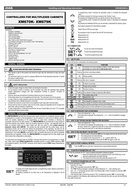
dIXEL Installing and Operating Instructions 1592023011CONTROLLERS FOR MULTIPLEXED CABINETS<strong>XM670K</strong>- <strong>XM679K</strong>CONTENTSCONTENTS ______________________________________________________________________________ 11. GENERAL WARNING _________________________________________________________________ 12. GENERAL DESCRIPTION _____________________________________________________________ 13. USER INTERFACE ___________________________________________________________________ 14. FAST ACCESS MENU_________________________________________________________________ 25. THE SECTION MENU _________________________________________________________________ 26. REAL TIME CLOCK FUNCTIONS (If present) ______________________________________________ 27. ELECTRONIC EXPANSION VALVE MENU (ONLY FOR <strong>XM679K</strong>)______________________________ 28. CONTROLLING LOADS _______________________________________________________________ 29. PARAMETER LIST ___________________________________________________________________ 310. DIGITAL INPUTS _____________________________________________________________________ 511. INSTALLATION AND MOUNTING _______________________________________________________ 512. ELECTRICAL CONNECTIONS __________________________________________________________ 613. RS485 SERIAL LINE __________________________________________________________________ 614. USE OF THE PROGRAMMING “HOT KEY“ ________________________________________________ 615. ALARM SIGNALS ____________________________________________________________________ 616. TECHNICAL DATA ___________________________________________________________________ 617. CONNECTIONS______________________________________________________________________ 618. DEFAULT SETTING VALUES___________________________________________________________ 71. GENERAL WARNING1.1 PLEASE READ BEFORE USING THIS MANUAL• This manual is part of the product and should be kept near the instrument for easy and quickreference.• The instrument shall not be used for purposes different from those described hereunder. It cannotbe used as a safety device.• Check the application limits before proceeding.1.2 SAFETY PRECAUTIONS• Check the supply voltage is correct before connecting the instrument.• Do not expose to water or moisture: use the controller only within the operating limits avoidingsudden temperature changes with high atmospheric humidity to prevent formation ofcondensation• Warning: disconnect all electrical connections before any kind of maintenance.• Fit the probe where it is not accessible by the End User. The instrument must not be opened.• In case of failure or faulty operation send the instrument back to the distributor or to “Dixell S.p.A.”(see address) with a detailed description of the fault.• Consider the maximum current which can be applied to each relay (see Technical Data).• Ensure that the wires for probes, loads and the power supply are separated and far enough fromeach other, without crossing or intertwining.• In case of applications in industrial environments, the use of mains filters (our mod. FT1) in parallelwith inductive loads could be useful.2. GENERAL DESCRIPTIONThe <strong>XM670K</strong>/<strong>XM679K</strong> are high level microprocessor based controllers for multiplexed cabinets suitablefor applications on medium or low temperature. It can be inserted in a LAN of up to 8 different sectionswhich can operate, depending on the programming, as stand alone controllers or following thecommands coming from the other sections. The <strong>XM670K</strong>/<strong>XM679K</strong> are provided with 6 relay outputs tocontrol the solenoid valve, defrost - which can be either electrical or hot gas - the evaporator fans, thelights, an auxiliary output and an alarm output and with one output to drive pulsed electronicexpansion valves (only <strong>XM679K</strong>). The devices are also provided with four probe inputs, one fortemperature control, one to control the defrost end temperature of the evaporator, the third for thedisplay and the fourth can be used for application with virtual probe or for inlet/outlet air temperaturemeasurement. The model <strong>XM679K</strong> is provided by other two probes that have to be used for superheatmeasurement and regulation. Finally, the <strong>XM670K</strong>/<strong>XM679K</strong> are equipped with the three digital inputs(free contact) fully configurable by parameters.The instruments are equipped with the HOTKEY connector that permits to be programmed in a simpleway. Direct serial output RS485 ModBUS-RTU compatible permits a simple XWEB interfacing. RTCare available as options. The HOTKEY connector can be used to connect X-REP display (Depending onthe model).3. USER INTERFACETo display and modify target set point; in programming mode it selects a parameter orconfirm an operation.By holding it pressed for 3s when max or min temperature is displayed it will beerased.BARPSIIn programming mode it browses the parameter codes or increases the displayedvalue.By holding it pressed for 3s the give access to the “Section” menu.By pressing and releasing this key you get the access to fast access menuin programming mode it browses the parameter codes or decreases the displayedvalue.By pressing and releasing this key you can activate or deactivate the auxiliary outputBy holding it pressed for 3s the defrost is started.Switch ON and OFF the room light.By pressing for about 3s switch ON and OFF the instrument.Measurement unitMeasurement unitMeasurement unitMeasurement unitKEY COMBINATIONS+ To lock and unlock the keyboard.+ To enter the programming mode.+ To exit the programming mode.3.1 USE OF LEDSEach LED function is described in the following table.LED MODE FUNCTIONONCompressor and valve regulation enabled, to see valve openingpercentage you should see the fast access menuFlashing Anti-short cycle delay enabledONDefrost enabledFlashing Drip time in progressONONONAn alarm is occurringEnergy saving enabledThe fan is runningFlashing Door opened or delay to restart fan after defrostAUX ON The auxiliary relay is ON°C/°F/Bar/PSI ON Measurement unit°C/°F/Bar/PSI Flashing Programming phaseON The controller is working in “ALL” modeFlashing The controller is working in remote virtual display modeFlashing During the CLOCK modification (if clock is present)3.2 HOW TO ENTER INTO FAST ACCESS MENU1. Press and release the o key.2. First Label will be displayed. By pressing the o or n keys it’s possible to navigatethe menu3.3 HOW TO SEE THE MAX AND MIN TEMPERATURE RECORDED1. Press and release the o key.2. First Label will be displayed. By pressing the o or n keys it’s possible to navigatethe menu. Search the L°t label and press SET to see minimum temperature; searchthe H°t label and press SET to see maximum temperature;3.4 HOW TO SEE AND MODIFY THE SET POINT1. Push for about 3 seconds the SET key: the display will show the Set point value;2. The measurement unit starts blinking;3. To change the Set value push the o or n arrows within 10s.4. To store the new set point value push the SET key again or wait 10s.3.5 HOW TO START A MANUAL DEFROSTPush the DEF key for more than 3 seconds and a manual defrost will start.3.6 TO ENTER IN PARAMETERS LIST “PR1”To enter the parameter list “Pr1” (user accessible parameters) operate as follows:1. Enter the Programming mode by pressing the SET and DOWN key for few+ SET seconds (measurement unit starts blinking).2. The instrument will show the first parameter present in “Pr1”3.7 TO ENTER IN PARAMETERS LIST “PR2”To access parameters in “Pr2”:1. Enter the “Pr1” level.2. Select “Pr2” parameter and press the “SET” key.3. The “PAS” flashing message is displayed, shortly followed by “0 - -” with a flashing zero.4. Use oor n to input the security code in the flashing digit; confirm the figure by pressing “SET”.The security code is “321“.5. If the security code is correct the access to “Pr2” is enabled by pressing “SET” on the last digit.Another possibility is the following: after switching ON the instrument the user can push Set and DOWNkeys within 30 seconds.1592023011 <strong>XM670K</strong>_<strong>XM679K</strong> GB r1.0 2009.01.15.doc <strong>XM670K</strong> - <strong>XM679K</strong> 1/9
dIXEL Installing and Operating Instructions 1592023011NOTE: each parameter in “Pr2” can be removed or put into “Pr1” (user level) by pressing “SET” + n.When a parameter is present in “Pr1” LED is on.3.8 HOW TO CHANGE THE PARAMETER VALUE1. Enter the Programming mode.2. Select the required parameter with o or n.3. Press the “SET” key to display its value (measurement unit starts blinking).4. Use o or n to change its value.5. Press “SET” to store the new value and move to the following parameter.To exit: Press SET + UP or wait 15s without pressing a key.NOTE: the new programming is stored even when the procedure is exited by waiting the time-out.3.9 ON/OFF FUNCTIONBy pushing the ON/OFF key, the instrument shows “OFF”. During the OFF status, all therelays are switched OFF and the regulations are stopped; if a monitoring system isconnected, it does not record the instrument data and alarms.N.B. During the OFF status the Light and AUX buttons are active.4. FAST ACCESS MENUFAST ACCESS MENUHM Fast access to Clock settings; (if present)An Fast access to analog output reading; (if present)SH Superheat: shows the actual superheat value; (Only <strong>XM679K</strong>)oPP Valve opening percentage: shows actual opening percentage of the valve; (Only <strong>XM679K</strong>)dP1 Probe 1 value displaying shows the temperature measured by probe 1;dP2 Probe 2 value displaying shows the temperature measured by probe 2;dP3 Probe 3 value displaying shows the temperature measured by probe 3;dp4 Probe 4 value displaying shows the temperature measured by probe 4;dP5 Probe value displaying shows the temperature value measured by probe 5; (Only <strong>XM679K</strong>)dP6 Probe 6 value displaying shows the temperature measured by probe 6; (Only <strong>XM679K</strong>)dPP Pressure probe value shows the value of pressure measured by pressure transducer; (Only<strong>XM679K</strong>)rPP Remote pressure probe value show the value of pressure received by remote pressure probeconnected to other XM600K device; (Only <strong>XM679K</strong>)L°t minimum measured temperature shows the minimum temperature read by the regulation probe;H°t Maximum measured temperature shows the maximum temperature read by the regulationprobe;dPr Virtual regulation probe value shows the value measured by virtual regulation probe;dPd Virtual defrost probe value shows the value measured by virtual defrost probe;dPF Virtual fans probe value shows the value measured by virtual fan probe;rSE Real set point: shows the set point used during the energy saving cycle or during the continuouscycle.5. THE SECTION MENUThis menu allows the user to access to a particular feature of the XM series related to the LAN (LocalArea Network) of controllers. A single keyboard, depending on the programming of this menu, is able tocontrol either the module of the local section of the LAN or ALL. The possibilities are: LOC: thekeyboard controls and display the value, the status and the alarms of the local section of the LAN; ALL:the command given by the keyboard are effective on all the sections of the LAN.1. Push the o key for more than 3 seconds2. The label corresponding to the section controlled by the keyboard will be displayed.3. With o or n key select the section you want to control.4. Press “Set” key to confirm and exit6. REAL TIME CLOCK FUNCTIONS (IF PRESENT)The following functions are available only if the Real Time Clock is present. To get access to real timeclock submenu:1. Enter the Programming mode by pressing the SET and DOWN key for fewseconds (measurement unit starts blinking).+ SET2. The instrument will show RTC label;3. Press SET. You are in RTC function menu;6.1 TO SET CURRENT TIME AND DAYHur Current hour (0 ÷ 23 h)Min Current minute (0 ÷ 59min)dAY Current day (Sun ÷ SAt)Hd1 First weekly holiday (Sun ÷ nu) Set the first day of the week which follows the holiday times.Hd2 Second weekly holiday (Sun ÷ nu) Set the second day of the week which follows the holidaytimes.Hd3 Third weekly holiday (Sun ÷ nu) Set the third day of the week which follows the holiday times.Sd1÷Sd6 Holiday defrost start (0 ÷ 23h 50 min.) These parameters set the beginning of the eightprogrammable defrost cycles on holidays. Ex. When Sd2 = 3.4 the second defrost starts at 3.40 onholidays.To disable a defrost cycle set it to “nu”(not used). Ex. If Ld6=nu ; the sixth defrost cycle isdisabled7. ELECTRONIC EXPANSION VALVE MENU (ONLY FOR <strong>XM679K</strong>)1. Enter the Programming mode by pressing the SET and DOWN key for fewseconds (measurement unit starts blinking).+ SET2. Press arrows until the instrument shows EEU label;3. Press SET. You are now in EEV function menu;8. CONTROLLING LOADS8.1 THE SOLENOID VALVEThe regulation is performed according to the temperature measured by the thermostat probe that can bephysical probe or virtual probe obtained by a weighted average between two probes (see parameterstable description) with a positive differential from the set point. If the temperature increases and reachesset point plus differential the solenoid valve is opened and then it is closed when the temperaturereaches the set point value again.In case of fault in the thermostat probe the opening and closing time of solenoid valve is configured by“Con” and “CoF” parameters.8.2 STANDARD REGULATION AND CONTINUOUS REGULATIONThe regulation can be performed in two ways: the goal of the first way (standard regulation) isreaching the best superheat via a classic temperature regulation obtained using hysteresis. The secondway, permits to use the valve to realise an high performance temperature regulation with a good factorof superheat precision. This second possibility, it can be used only in centralized plants and it isavailable only with electronic expansion valve by selecting CrE=Y parameter.In any case, the regulation is performed via PI regulator that gives the opening percentage to the valvevia PWM modulation explained as follow. Opening percentage is obtained from average of OpeningTime respect to CyP time period like following diagram:With opening percentage we mean percentage of cycle period where valve is open. For example, ifCyP=6s (standard value) by saying: “The valve is opened at 50%”; this means that the valve is openedfor 3s during cycle period.First kind of regulation:In this case, the Hy parameter is the differential for standard ON/OFF regulation. In this case the intparameter is neglected. The regulation follow this diagram:Second kind of regulation – Continuous regulation (only <strong>XM679K</strong>):In this case, the Hy parameter is the proportional band of PI in charge of room temperature regulationand we advise to used at least Hy=5.0°C/10°F. The int parameter is the integral time of the same PIregulator. Increasing int parameter the PI regulator become slow in reaction and of course is true viceversa. To disable the integral part of regulation you should set int=0.N.B. Hd1,Hd2,Hd3 can be set also as “nu” value (Not Used).6.2 TO SET ENERGY SAVING TIMESILE Energy Saving cycle start during workdays: (0 ÷ 23h 50 min.) During the Energy Saving cyclethe set point is increased by the value in HES so that the operation set point is SET + HES.dLE Energy Saving cycle length during workdays: (0 ÷ 24h 00 min.) Sets the duration of the EnergySaving cycle on workdays.ISE Energy Saving cycle start on holidays. (0 ÷ 23h 50 min.)dSE Energy Saving cycle length on holidays (0 ÷ 24h 00 min.)HES Temperature increase during the Energy Saving cycle (-30÷30°C / -54÷54°F) sets theincreasing value of the set point during the Energy Saving cycle.6.3 TO SET TIMED DEFROST PARAMETERSLd1÷Ld6 Workday defrost start (0 ÷ 23h 50 min.) These parameters set the beginning of the eightprogrammable defrost cycles during workdays. Ex. When Ld2 = 12.4 the second defrost starts at12.40 during workdays.8.3 DEFROSTDefrost startingIn any case, the device check the temperature read by configured defrost probe before startingdefrost procedure, after that:- (If RTC is present)Two defrost modes are available through the “tdF” parameter: defrost withelectrical heater and hot gas defrost. The defrost interval is controlled by parameter “EdF”: (EdF =rtc) defrost is made in real time depending on the hours set in the parameters Ld1..Ld6 in workdaysand in Sd1…Sd6 on holidays; (EdF = in) the defrost is made every “IdF” time;- defrost cycle starting can be operated locally (manual activation by means of the keyboard or digitalinput or end of interval time) or the command can come from the Master defrost unit of the LAN. In1592023011 <strong>XM670K</strong>_<strong>XM679K</strong> GB r1.0 2009.01.15.doc <strong>XM670K</strong> - <strong>XM679K</strong> 2/9
dIXEL Installing and Operating Instructions 1592023011this case the controller will operate the defrost cycle following the parameters it has programmed but,at the end of the drip time, will wait that all the other controllers of the LAN finish their defrost cyclebefore to re-start the normal regulation of the temperature according to dEM parameter;- Every time any of the controller of the LAN begin a defrost cycle it issue the command into thenetwork making all the other controllers start their own cycle. This allows a perfect synchronisation ofthe defrost in the whole multiplexed cabinet according to LMd parameter;- Selecting dPA and dPb probes and by changing the dtP and ddP parameters the defrost can bestarted when the difference between dPA and dPb probes is lower than dtP for all ddP time. This isuseful to start defrost when a low thermal exchange is detected. If ddP=0 this function is disabled;Defrost ending- When defrost is started via rtc, the maximum duration of defrost is obtained from Md parameter andthe defrost end temperature is obtained from dtE parameter (and dtS if two defrost probes areselected).- If dPA and dPb are present and d2P=y the instrument stops the defrost procedure when dPA ishigher than dtE temperature and dPb is higher than dtS temperature;At the end of defrost the drip time is controlled through the “Fdt” parameter.8.4 FANSCONTROL WITH RELAYThe fan control mode is selected by means of the “FnC” parameter:C-n = running with the solenoid valve, OFF during the defrost;C-y = running with th1e solenoid valve, ON during the defrost;O-n = continuous mode, OFF during the defrost;O-y = continuous mode, ON during the defrost;An additional parameter “FSt” provides the setting of temperature, detected by the evaporator probe,above which the fans are always OFF. This can be used to make sure circulation of air only if histemperature is lower than set in “FSt”.CONTROL WITH ANALOG OUTPUT (if present)8.5 ANTI SWEAT HEATERS (IF PRESENT)The modulating output (trA=rEG) works inproportional way (excluding the first AMtseconds where the fans speed is the maximum).The regulation set point is relative to regulationset point and is indicated by ASr, theproportional band is always located aboveSET+ASr value and its value is PbA. The fan areat minimum speed (AMi) when the temperatureread by fan probe is SET+ASr and the fan is atmaximum speed (AMA) when the temperature isSET+ASr+PbA.This control is performed when trA=AC. In this case, there is two way to control the anti-sweat heaters:• Without real dew-point information: in this case the default value for dew-point is used(SdP parameter).• Receiving dew-point from XWEB5000 system: the SdP parameter is overwrote when validvalue for dew-point is received from XWEB.8.6 AUXILIARY OUTPUTThe P4 probe is used to perform the regulationand it should be placed on the showcase glass.In case of P4 error or if P4 is absent the output isat AMA value for the AMt time then the output isat 0 value for the time 255-AMt time performinga simple PWM modulation.The auxiliary output is switch ON and OFF by means of the corresponding digital input or by pressingand releasing the down arrow key.9. PARAMETER LISTREGULATIONrtC Access to CLOCK submenu (if present);EEU Access to EEV submenu (only <strong>XM679K</strong>);Hy Differential: (0,1÷25,5°C; 1÷45°F): Intervention differential for set point, always positive.Solenoid valve Cut IN is Set Point Plus Differential (Hy). Solenoid valve Cut OUT is when thetemperature reaches the set point.Int Integral time for room temperature regulation (Only <strong>XM679K</strong>): (0 ÷ 255 s) integral time forroom temperature PI regulator. 0= no integral action;CrE Continuous regulation activation (Only <strong>XM679K</strong>): (n÷Y) n= standard regulation; Y=continuous regulation. Use it only in centralized plants;LS Minimum set point limit: (-55.0°C÷SET; -67°F÷SET) Sets the minimum acceptable value forthe set point.US Maximum set point limit: (SET÷150°C; SET÷302°F) Set the maximum acceptable value forset point.OdS Outputs activation delay at start up: (0÷255 min) This function is enabled at the initial startup of the instrument and inhibits any output activation for the period of time set in theparameter. (AUX and Light can work)AC Anti-short cycle delay: (0÷60 min) interval between the solenoid valve stop and the followingrestart.CCt Compressor ON time during continuous cycle: (0.0÷24.0h; resolution 10min) Allows to setthe length of the continuous cycle: compressor stays on without interruption for the CCt time.Can be used, for instance, when the room is filled with new products.CCS Set point for continuous cycle: (-55÷150°C / -67÷302°F) it sets the set point used during thecontinuous cycle.ConCoFDISPLAYCFPrUPMUPMdrESLodreddLyrPArPbrPEsolenoid valve ON time with faulty probe: (0÷255 min) time during which the solenoid valveis active in case of faulty thermostat probe. With COn=0 solenoid valve is always OFF.solenoid valve OFF time with faulty probe: (0÷255 min) time during which the solenoid valveis off in case of faulty thermostat probe. With COF=0 solenoid valve is always active.Temperature measurement unit: °C=Celsius; °F=Fahrenheit. !!! WARNING !!! When themeasurement unit is changed the parameters with temperature values have to be checked.Pressure mode: (rEL or AbS) it defines the mode to use the pressure. !!! WARNING !!! thesetting of PrU is used for all the pressure parameters. If PrU=rEL all pressure parameters are inrelative pressure unit, if PrU=AbS all pressure parameters are in absolute pressure unit. (Only<strong>XM679K</strong>)Pressure measurement unit: (bAr – PSI - MPA) it selects the pressure measurement units.MPA= the value of pressure measured by kPA*10. (Only <strong>XM679K</strong>)Way of displaying pressure : (tEM - PrE) it permits showing the value measured by pressureprobe with tEM= temperature or by PrE= pressure; (Only <strong>XM679K</strong>)Resolution (for °C): (in = 1°C; dE = 0.1 °C) allows decimal point display;Instrument display: (nP; P1; P2, P3, P4, P5, P6, tEr, dEF) it selects which probe is displayedby the instrument. P1, P2, P3, P4, P5, P6, tEr= virtual probe for thermostat, dEF= virtual probefor defrost.Remote display: (nP; P1; P2, P3, P4, P5, P6, tEr, dEF) it selects which probe is displayed bythe X-REP. P1, P2, P3, P4, P5, P6, tEr= virtual probe for thermostat, dEF= virtual probe fordefrost.Display delay: (0 ÷24.0 m; resolution 10s) when the temperature increases, the display isupdated of 1 °C/1°F after this time.Regulation probe A: (nP; P1; P2, P3, P4, P5) first probe used to regulate room temperature. IfrPA=nP the regulation is performed with real value of rPb.Regulation probe B: (nP; P1; P2, P3, P4, P5) second probe used to regulate roomtemperature. If rPb=nP the regulation is performed with real value of rPARegulation virtual probe percentage: (0 ÷ 100%) it defines the percentage of the rPA respectto rPb. The value used to regulate room temperature is obtained by:value_for_room = (rPA*rPE + rPb*(100-rPE))/100ELECTRONIC EXPANSION VALVE SUBMENU (Only <strong>XM679K</strong>)FtY Kind of gas (R22, 134, 404, 407, 410, 507,CO2): Type of gas used by plant. Fundamentalparameter for correct functioning of all system.SSH Superheat set point: [0.1°C ÷ 25.5°C] [1°F ÷ 45°F] it’s the value used to regulate superheatCyP Cycle Period: (1 ÷ 15s) it permits to set cycle time;Pb Proportional band: (0.1 ÷ 60.0 / 1÷108°F) PI proportional band;rS Band Offset: (-12.0 ÷ 12.0°C / -21÷21°F) PI band offset;inC Integration time: (0 ÷ 255s) PI integration time;PEO Probe Error opening percentage: (0÷100%) if a temporary probe error occurs, valve openingpercentage is PEo until PEd time is elapsed;PEd Probe Error delay before stopping regulation: (0÷239 sec. – On=unlimited) if probe errorduration is bigger than PEd then valve totally closes. Pf message is showed. If PEd=On valveopening is PEo until probe error finishes;OPE Start opening Percentage: (0÷100%) Opening valve percentage when start function is active.This phase duration is SFd time;SFd Start Function duration: (0.0 ÷ 42.0 min: resolution 10s) It sets start function duration andpost-defrost duration. During this phase the alarms are neglected;OPd Opening Percentage after defrost phase: (0÷100%) Opening valve percentage when afterdefrost function is active. This phase duration is Pdd time;Pdd Post Defrost Function duration: (0.0 ÷ 42.0 min: resolution 10s) It sets start function durationand post-defrost duration. During this phase the alarms are neglected;MnF Maximum opening percentage at normal Functioning: (0÷100%) during regulation it setsthe maximum valve opening percentage;dCL Delay before stopping valve regulation: (0 ÷ 255s) When the cooling request goes off, theelectronic valve regulation can go on for the dCL time in order to prevent uncontrolledsuperheat variation;Fot Forced opening percentage: (0÷100% - nu) it permits to force the valve opening to thespecified value. This value overwrite the value calculated by PID algorithm. !!!! WARNING !!!!to obtain the correct superheat regulation you have to set Fot=nu;tPP Type of Pressure Transducer: (PP – LAn) it sets type of pressure transducer to use: PP=4÷20mA pressure transducer or ratiometric transducer 0÷5V depending on P5C parameter,LAn= the pressure signal arrives from another XM600K; Referred to Pb5PA4 Probe value At 4mA or At 0V: (-1.0 ÷ P20 bar / -14 ÷ PSI / -10 ÷ P20 kPA*10) pressure valuemeasured by probe at 4mA or at 0V (related to PrM parameter) Referred to Pb5P20 Probe value 20mA or At 5V: (PA4 ÷ 50.0 bar / 725 psi / 500 kPA*10) pressure valuemeasured by probe at 20mA or at 5V (related to PrM parameter) Referred to Pb5LPL Lower Pressure Limit for superheat regulation: (PA4 ÷ P20 bar / psi / kPA*10) when suctionpressure comes down to LPL the regulation is performed with a LPL fixed value for pressure,when pressure comes back to LPL the normal pressure value is used. (related to PrMparameter)MOP Maximum Operating Pressure threshold: (PA4 ÷ P20 bar / psi / kPA*10) if suction pressureexceeds maximum operating pressure value, instrument signals situation with MOP alarm.(related to PrM parameter)LOP Lowest Operating Pressure threshold: (PA4 ÷ P20 bar / psi / kPA*10) if the suction pressurecomes down to this value a low pressure alarm is signalled with LOP alarm. (related to PrMparameter)dML delta MOP-LOP: (0 ÷ 100%) when a MOP alarm occurs valve will close of the dML percentageevery cycle period until MOP alarm is active. When LOP occurs valve will open of the dMLpercentage every cycle period until LOP alarm is active.MSH Maximum Superheat alarm: (LSH ÷ 80.0°C / LSH ÷ 144°F) when superheat exceeds thisvalue an high superheat alarm is signalled after interval SHdLSH Lowest Superheat alarm: (0.0 ÷ MSH °C / 0÷MSH °F) when superheat goes down to thisvalue a low superheat alarm is signalled after interval SHdSHy Superheat alarm Hysteresis: (0.1÷25.5°C/1÷45°F) hysteresis for superheat alarmSHddeactivationSuperheat alarm activation delay: (0.0 ÷ 42.0 min: resolution 10s) when a superheat alarmoccurs, the time SHd have to pass before signalling alarm;1592023011 <strong>XM670K</strong>_<strong>XM679K</strong> GB r1.0 2009.01.15.doc <strong>XM670K</strong> - <strong>XM679K</strong> 3/9
dIXEL Installing and Operating Instructions 1592023011FrCDEFROSTFast-recovery Constant: (0÷100 s) permits to increase integral time when SH is below the setpoint.If FrC=0 fast recovery function is disabled.dPA defrost Probe A: (nP; P1; P2, P3, P4, P5) first probe used for defrost. If rPA=nP the regulationis performed with real value of dPb.dPb defrost Probe B: (nP; P1; P2, P3, P4, P5) second probe used for defrost. If rPB=nP theregulation is performed with real value of dPA.dPE defrost virtual probe percentage: (0÷100%) it defines the percentage of the dPA respect todPb. The value used to regulate room temperature is obtained by:value_for_defrost= (dPA*dPE + dPb*(100-dPE))/100tdF Defrost type: (EL – in) EL = electrical heater; in = hot gas;EdF Defrost mode: (rtc – in) (only if RTC is present) rtc= defrost activation via RTC; in= defrostactivation with idf.Srt Heater set point during defrost: (-55.0 ÷ 150.0°C; -67 ÷ 302°F) if tdF=EL during the defrostthe defrost relay perform an ON/OFF regulation with Srt as set point.Hyr Differential for heater: (0.1°C ÷ 25.5°C , 1°F ÷ 45°F) the differential for heater;tod Time out for heater: 0 ÷ 255 (min.) if the defrost probe temperature is bigger than Srt for alltod time the defrost ends altough the defrost probe temperature is lower than dtE or dtS. Itpermits to reduce defrost duration;dtP Minimum temperature difference to start defrost: [0.1°C ÷ 50.0°C] [1°F ÷ 90°F] if thedifference between the two defrost probes stays lower than dtP for all ddP time the defrost isactivated;ddP Delay before starting defrost (related to dtP): (0 ÷ 60 min) delay related to dtP.d2P Defrost with two probes: (n – Y) n= only the dPA probe is used to defrost management; Y=defrost is managed with dPA probe and dPb probe. Defrost can performed only if both probevalue are lower than dtE for dPA probe and dtS for dPb probe;dtE Defrost termination temperature (Probe A): (-55,0÷50,0°C; -67÷122°F) (Enabled only whenthe evaporator probe is present) sets the temperature measured by the evaporator probe dPAwhich causes the end of defrost;dtS Defrost termination temperature (Probe B): (-55,0÷50,0°C; -67÷122°F) (Enabled only whenthe evaporator probe is present) sets the temperature measured by the evaporator probe dPbwhich causes the end of defrost;IdF Interval between defrosts: (0÷120h) Determines the time interval between the beginning oftwo defrost cycles;MdF Maximum duration of defrost: (0÷255 min) When dPA and dPb aren’t present, it sets thedefrost duration, otherwise it sets the maximum duration for defrost;dSd Start defrost delay: (0 ÷ 255 min) This is useful when different defrost start times arenecessary to avoid overloading the plant.dFd Display during defrost: rt = real temperature; it = temperature reading at the defrost start; Set= set point; dEF = “dEF” label;dAd Defrost display time out: (0÷255 min) Sets the maximum time between the end of defrost andthe restarting of the real room temperature display.Fdt Drain down time: (0÷255 min.) time interval between reaching defrost termination temperatureand the restoring of the control’s normal operation. This time allows the evaporator to eliminatewater drops that might have formed due to defrost.dPo First defrost after start-up: y = Immediately; n = after the IdF timedAF Defrost delay after continuous cycle: (0÷23.5h) time interval between the end of the fastfreezing cycle and the following defrost related to it.FANFPA Fan probe A: (nP; P1; P2, P3, P4, P5) first probe used for fan. If FPA=nP the regulation isperformed with real value of FPB;FPB Fan probe B: (nP; P1; P2, P3, P4, P5) second probe used for defrost. If FPB=nP the regulationis performed with real value of FPB;FPE Fan virtual probe percentage: (0÷100%) it defines the percentage of the FPA respect to FPb.The value used to regulate room temperature is obtained by:value_for_defrost= (FPA*FPE + FPb*(100-FPE))/100FnC Fan operating mode: C-n = running with the solenoid valve, OFF during the defrost; C-y =running with the solenoid valve, ON during the defrost; O-n = continuous mode, OFF during thedefrost; O-y = continuous mode, ON during the defrost;Fnd Fan delay after defrost: (0÷255 min) The time interval between the defrost end andevaporator fans start.FCt Temperature differential avoiding short cycles of fans (0.0°C ÷ 50.0°C; 0°F ÷ 90°F) If thedifference of temperature between the evaporator and the room probes is more than the valueof the Fct parameter, the fans are switched on;FSt Fan stop temperature: (-50÷110°C; -58÷230°F) setting of temperature, detected byevaporator probe, above which the fan is always OFF.FHy Differential to restart fan: (0.1°C ÷ 25.5°C) (1°F ÷ 45°F) when stopped, fan restarts when fanprobe reaches FSt-FHy temperature;FodFonFoFFan activation time after defrost: (0 ÷ 255 min.) it forces fan activation for indicated time;Fan ON time: (0÷15 min) with Fnc = C_n or C_y, (fan activated in parallel with compressor). itsets the evaporator fan ON cycling time when the compressor is off. With Fon =0 and FoF ≠ 0the fan are always off, with Fon=0 and FoF =0 the fan are always off.Fan OFF time: (0÷15 min) with Fnc = C_n or C_y, (fan activated in parallel with compressor). itsets the evaporator fan off cycling time when the compressor is off. With Fon =0 and FoF ≠ 0the fan are always off, with Fon=0 and FoF =0 the fan are always off.MODULATING OUTPUT (AnOUT) if presenttrA Kind of regulation with PWM output: (UAL – rEG – AC) it selects the functioning for the PWMoutput if CoM isn’t equal to OA7. UAL= the output is at FSA value; rEG= the output is regulatedwith fan algorithm described in fan section; AC= anti-sweat heaters control (require theXWEB5000 system);SOA Fixed value for analog output: (0 ÷ 100%) value for the output if trA=UAL;SdP Default value for Dew point: (-55,0÷50,0°C; -67÷122°F) default value of dew point used whenthere is no supervising system (XWEB5000). Used only when trA=AC;ASr Dew-point offset (trA=AC) / Differential for modulating fan regulation (trA=rEG): (-25.5°C÷ 25.5°C) (-45°F ÷ 45°F);PbA Differential for anti-sweat heaters: (0.1°C ÷ 25.5°C) (1°F ÷ 45°F)AMi Minimum value for analog output: (0÷AMA)AMA Maximum value for analog output: (Ami ÷ 100)AMtALARMSAnti-sweat heaters cycle period (trA=AC)/ Time with fan at maximum speed (trA=rEG):(0÷255 s) when the fan starts, during this time the fan is at maximum speed;rAL Probe for temperature alarm: (nP - P1 - P2 - P3 - P4 - P5 – tEr) it selects the probe used tosignal alarm temperatureALC Temperature alarm configuration: rE = High and Low alarms related to Set Point; Ab = Highand low alarms related to the absolute temperature.ALU High temperature alarm setting: (ALC= rE, 0 ÷ 50°C or 90°F / ALC= Ab, ALL ÷ 150°C or302°F) when this temperature is reached and after the ALd delay time the HA alarm is enabled.ALL Low temperature alarm setting: (ALC = rE , 0 ÷ 50 °C or 90°F / ALC = Ab , - 55°C or - 67°F ÷ALU) when this temperature is reached and after the ALd delay time, the LA alarm is enabled.AHy Differential for temperature alarm: (0.1°C ÷ 25.5°C / 1°F ÷ 45°F) Intervention differential forrecovery of temperature alarm;ALd Temperature alarm delay: (0÷255 min) time interval between the detection of an alarmcondition and the corresponding alarm signalling.dLU High temperature alarm (defrost probe): (ALC= rE, 0 ÷ 50°C or 90°F / ALC= Ab, ALL ÷150°C or 302°F) when this temperature is reached and after the ddA delay time the HAd alarmis enabled.dLL Low temperature alarm (defrost probe): (ALC = rE , 0 ÷ 50 °C or 90°F / ALC = Ab , - 55°C or- 67°F ÷ ALU) when this temperature is reached and after the ALd delay time, the LAd alarm isenabled.dAH Differential for temperature alarm (defrost probe): (0.1°C ÷ 25.5°C / 1°F ÷ 45°F)ddAIntervention differential for recovery of temperature alarm;Temperature alarm delay (defrost probe): (0÷255 min) time interval between the detection ofan alarm condition and the corresponding alarm signalling.FLU High temperature alarm (defrost probe): (ALC= rE, 0 ÷ 50°C or 90°F / ALC= Ab, ALL ÷150°C or 302°F) when this temperature is reached and after the FAd delay time the HAF alarmis enabled.FLLFAHFAddAOEdAdotStiStdOA6Low temperature alarm (defrost probe): (ALC = rE , 0 ÷ 50 °C or 90°F / ALC = Ab , - 55°C or- 67°F ÷ ALU) when this temperature is reached and after the FAd delay time, the LAF alarm isenabled.Differential for temperature alarm (defrost probe): (0.1°C ÷ 25.5°C / 1°F ÷ 45°F)Intervention differential for recovery of temperature alarm;Temperature alarm delay (defrost probe): (0÷255 min) time interval between the detection ofan alarm condition and the corresponding alarm signalling.Delay of temperature alarm at start-up: (0min÷23h 50min) time interval between thedetection of the temperature alarm condition after the instrument power on and the alarmsignalling.Alarm delay at the end of defrost: (0÷255 min) Time interval between the detection of thetemperature alarm condition at the end of defrost and the alarm signalling.Temperature alarm exclusion after door open:Stop regulation interval (Only <strong>XM679K</strong>): (0.0÷24.0 hours: tens of minutes) after regulatingcontinuously for Sti time, the valve closes for Std time in order to prevent ice creation.Stop duration (Only <strong>XM679K</strong>): (0÷60 min.) it defines stop regulation time after Sti. During thisstop display shows StP messageSixth relay configuration (CPr-dEF-Fan-ALr-LiG-AUS-db-OnF): CPr= relay works as acompressor or solenoid valve relay; dEF= relay works as defrost relay; Fan= relay works as aFan relay; ALr= activation with alarm conditions; LiG= light activation; AUS= auxiliary relay, itcan be switched ON/OFF also by key; db= dead band regulation (not compatible with CrE=y);OnF= ON/OFF functioning;OPTIONAL OUTPUT (AnOUT) if presentOA7 Modulating output configuration (if CoM=0A7): (CPr - dEF - FAn - ALr - LiG - AUS – db) itselects the functioning of the modulating output in case of CoM=OA7: CPr= compressor; dEF=defrost; FAn= Fan; Alr= Alarm; LiG= Light; AUS= auxiliary; db= neutral zone (not available withCrE=Y);CoM Type of functioning modulating output:• For models with PWM / O.C. output PM5= PWM 50Hz; PM6= PWM 60Hz;OA7= two state, it can be used as an open collector output;• For models with 4÷20mA / 0÷10V output Cur= 4÷20mA current output;tEn= 0÷10V voltage output;AOP Alarm relay polarity: cL= normally closed; oP= normally opened;iAU Auxiliary output is unrelated to ON/OFF device status: n= if the instrument is switched offalso the auxiliary output is switched off; Y= the auxiliary output state is unrelated to the ON/OFFdevice statusDIGITAL INPUTSi1Pi1Fd1di2Pi2Fd2di3PDigital input 1 polarity: (cL – oP) CL: the digital input is activated by closing the contact; OP:the digital input is activated by opening the contact.Digital input 1 function: (EAL – bAL – PAL – dor – dEF – AUS – LiG – OnF – Htr – FHU – ES– Hdy) EAL= external alarm; bAL= serious external alarm; PAL= pressure switch activation;dor= door open; dEF= defrost activation; AUS= auxiliary activation; LiG= light activation; OnF=switch on/off the instrument; Htr= change type of action ; FHU= not used; ES= activate energysaving; Hdy= activate holiday function;Time interval/delay for digital input alarm: (0÷255 min.) Time interval to calculate the numberof the pressure switch activation when i1F=PAL. If I1F=EAL or bAL (external alarms), “d1d”parameter defines the time delay between the detection and the successive signalling of thealarm. If i1F=dor this is the delay to activate door open alarmDigital input 2 polarity: (cL – oP) CL : the digital input is activated by closing the contact; OP:the digital input is activated by opening the contact.Digital input 2 function: (EAL – bAL – PAL – dor – dEF – AUS – LiG – OnF – Htr – FHU – ES– Hdy) EAL= external alarm; bAL= serious external alarm; PAL= pressure switch activation;dor= door open; dEF= defrost activation; AUS= auxiliary activation; LiG= light activation; OnF=switch on/off the instrument; Htr= change type of action ; FHU= not used; ES= activate energysaving; Hdy= activate holiday function;Time interval/delay for digital input alarm: (0÷255 min.) Time interval to calculate the numberof the pressure switch activation when i2F=PAL. If I2F=EAL or bAL (external alarms), “d2d”parameter defines the time delay between the detection and the successive signalling of thealarm. If i2F=dor this is the delay to activate door open alarmDigital input 3 polarity: (cL – oP) CL : the digital input is activated by closing the contact; OP:the digital input is activated by opening the contact.1592023011 <strong>XM670K</strong>_<strong>XM679K</strong> GB r1.0 2009.01.15.doc <strong>XM670K</strong> - <strong>XM679K</strong> 4/9
dIXEL Installing and Operating Instructions 1592023011i3F Digital input 3 function: (EAL – bAL – PAL – dor – dEF – AUS – LiG – OnF – Htr – FHU – ES– Hdy) EAL= external alarm; bAL= serious external alarm; PAL= pressure switch activation;dor= door open; dEF= defrost activation; AUS= auxiliary activation; LiG= light activation; OnF=switch on/off the instrument; Htr= change type of action ; FHU= not used; ES= activate energysaving; Hdy= activate holiday function;d3d Time interval/delay for digital input alarm: (0÷255 min.) Time interval to calculate the numberof the pressure switch activation when i3F=PAL. If i3F=EAL or bAL (external alarms), “d3d”parameter defines the time delay between the detection and the successive signalling of thealarm. If i3F=dor this is the delay to activate door open alarmnPS Pressure switch number: (0 ÷15) Number of activation of the pressure switch, during the“d#d” interval, before signalling the alarm event (I2F= PAL). If the nPS activation in the didtime is reached, switch off and on the instrument to restart normal regulation.odc Compressor and fan status when open door: no = normal; Fan = Fan OFF; CPr =Compressor OFF; F_C = Compressor and fan OFF.rrd Outputs restart after doA alarm: no = outputs not affected by the doA alarm; yES = outputsrestart with the doA alarm;RTC SUBMENU (if present)CbP Clock Presence (n÷y): it permits to disable or enable the clock;Hur Current hour (0 ÷ 23 h)Min Current minute (0 ÷ 59min)dAY Current day (Sun ÷ SAt)Hd1 First weekly holiday (Sun ÷ nu) Set the first day of the week which follows the holiday times.Hd2 Second weekly holiday (Sun ÷ nu) Set the second day of the week which follows the holidaytimes.Hd3ILEdLEISEdSEHESThird weekly holiday (Sun ÷ nu) Set the third day of the week which follows the holiday times.Energy Saving cycle start during workdays: (0 ÷ 23h 50 min.) During the Energy Savingcycle the set point is increased by the value in HES so that the operation set point is SET +HES.Energy Saving cycle length during workdays: (0 ÷ 24h 00 min.) Sets the duration of theEnergy Saving cycle on workdays.Energy Saving cycle start on holidays. (0 ÷ 23h 50 min.)Energy Saving cycle length on holidays (0 ÷ 24h 00 min.)Temperature increase during the Energy Saving cycle (-30÷30°C / -54÷54°F) sets theincreasing value of the set point during the Energy Saving cycle.Ld1÷Ld6 Workday defrost start (0 ÷ 23h 50 min.) These parameters set the beginning of the eightprogrammable defrost cycles during workdays. Ex. When Ld2 = 12.4 the second defrost startsat 12.40 during workdays.Sd1÷Sd6 Holiday defrost start (0 ÷ 23h 50 min.) These parameters set the beginning of the eightprogrammable defrost cycles on holidays. Ex. When Sd2 = 3.4 the second defrost starts at 3.40on holidays.ENERGY SAVINGESPHESPELEnergy saving probe selection: (nP - P1 - P2 - P3 - P4 - P5 – tEr).Temperature increase during the Energy Saving cycle : (-30÷30°C / -54÷54°F) sets theincreasing value of the set point during the Energy Saving cycle.Energy saving activation when light is switched off: (n÷Y) n= function disabled; Y= energysaving is actived when the light is switched off and vice versa;LAN MANAGEMENTLMddEMLSPLdSLOFLLiLAULESLSdLPPStMDesfrost synchronisation: y= the section send a command to start defrost to oher controllers,n= the section don’t send a global defrost commandType of end defrost: n= the of the LAN defrost are indipendent; y= the end of the defrost aresynchronisated;L.A.N. set-point synchronisation: y= the section set-point, when modified, is updated to thesame value on all the other sections; n= the set-point value is modified only in the local sectionL.A.N. display synchronisation: y= the value displayed by the section is sent to all the othersections; n= the set-point value is modified only in the local sectionL.A.N. On/Off synchronisation this parameter states if the On/Off command of the section willact on all the other ones too: y= the On/Off command is sent to all the other sections; n= theOn/Off command acts only in the local sectionL.A.N. light synchronisation this parameter states if the light command of the section will acton all the other ones too: y= the light command is sent to all the other sections; n= the lightcommand acts only in the local sectionL.A.N. AUX output synchronisation this parameter states if the AUX command of the sectionwill act on all the other ones too: y= the light command is sent to all the other sections; n= thelight command acts only in the local sectionL.A.N. energy saving synchronisation this parameter states if the energy saving commandof the section will act on all the other ones too: y= the Energy Saving command is sent to all theother sections; n= the Energy Saving command acts only in the local sectionRemote probe display: this parameter states if the section has to display the local probe valueor the value coming from another section: y= the displayed value is the one coming fromanother section (which has parameter LdS = y); n= the displayed value is the local probe one.Remote pressure probe: n= the value of pressure probe is read from local probe; Y= the valueof pressure probe is sent via LAN;Solenoid activation via LAN: n= not used; Y= a generic cooling requests from LAN activatethe solenoid valve connected to compressor relay;PROBE CONFIGURATIONP1C Probe 1 configuration: (nP – Ptc – ntc – PtM) nP= not present; PtC= Ptc; ntc= Ptc; PtM=Pt1000;Ot Probe 1 calibration: (-12.0÷12.0°C/ -21÷21°F) allows to adjust possible offset of thethermostat probe.P2C Probe 2 configuration: (nP – Ptc – ntc – PtM) nP= not present; PtC= Ptc; ntc= Ptc; PtM=Pt1000;OE Probe 2 calibration: (-12.0÷12.0°C/ -21÷21°F) allows to adjust possible offsets of theevaporator probe.P3C Probe 3 configuration: (nP – Ptc – ntc – PtM) nP= not present; PtC= Ptc; ntc= Ptc; PtM=Pt1000;o3 Probe 3 calibration: (-12.0÷12.0°C/ -21÷21°F) allows to adjust possible offset of the probe 3.P4C Probe 4 configuration: (nP – Ptc – ntc – PtM) nP= not present; PtC= Ptc; ntc= Ptc; PtM=Pt1000;o4 Probe 4 calibration: (-12.0÷12.0°C/ -21÷21°F) allows to adjust possible offset of the probe 4.P5C Probe 5 configuration: (nP – Ptc – ntc – PtM – 420 – 5Vr) nP= not present; PtM= Pt1000;420= 4÷ 20mA; 5Vr= 0÷5V ratiometric; (Only <strong>XM679K</strong>)o5 Probe 5 calibration: (-12.0÷12.0°C/ -21÷21°F) allows to adjust possible offset of the probe 5.P6C(Only <strong>XM679K</strong>)Probe 6 configuration: (nP – Ptc – ntc – PtM) nP= not present; PtC= Ptc; ntc= Ptc; PtM=Pt1000; (Only <strong>XM679K</strong>)o6 Probe 6 calibration: (-12.0÷12.0°C/ -21÷21°F) allows to adjust possible offset of the probe 6.(Only <strong>XM679K</strong>)SERVICE – READ ONLYCLttMdLSnLanAdrRelPtbPr2Coling time percentage: it shows the effective cooling time calculated by XM600 duringregulation;Time to next defrost: it shows time before the next defrost if interval defrost is selected;L.A.N. section number (1 ÷ 5) Shows the number of sections available in the L.A.N.L.A.N. serial address (1 ÷ LSn) Identifies the instrument address inside local network ofmultiplexed cabinet controller.RS485 serial address (1÷247): Identifies the instrument address when connected to aModBUS compatible monitoring system.Release software: (read only) Software version of the microprocessor.Parameter table: (read only) it shows the original code of the dIXEL parameter map.Access to the protected parameter list (read only).10. DIGITAL INPUTSThe XM600 series can support up to 3 free of voltage contact configurable digital inputs (depending onthe models). They are configurable via i#F parameter10.1 GENERIC ALARM (EAL)As soon as the digital input is activated the unit will wait for “did” time delay before signalling the “EAL”alarm message. The outputs status don’t change. The alarm stops just after the digital input is deactivated.10.2 SERIOUS ALARM MODE (BAL)When the digital input is activated, the unit will wait for “did” delay before signalling the “BAL” alarmmessage. The relay outputs are switched OFF. The alarm will stop as soon as the digital input is deactivated.10.3 PRESSURE SWITCH (PAL)If during the interval time set by “d#d” parameter, the pressure switch has reached the number of activation ofthe “nPS” parameter, the “CA” pressure alarm message will be displayed. The compressor and the regulationare stopped. When the digital input is ON the compressor is always OFF. If the nPS activation in the d#d timeis reached, switch off and on the instrument to restart normal regulation.10.4 DOOR SWITCH INPUT (dor)It signals the door status and the corresponding relay output status through the “odc” parameter: no = normal(any change); Fan = Fan OFF; CPr = Compressor OFF; F_C = Compressor and fan OFF. Since the door isopened, after the delay time set through parameter “d#d”, the door alarm is enabled, the display shows themessage “dA” and the regulation restarts after rrd time. The alarm stops as soon as the external digital inputis disabled again. With the door open, the high and low temperature alarms are disabled.10.5 START DEFROST (DEF)It executes a defrost if there are the right conditions. After the defrost is finished, the normal regulationwill restart only if the digital input is disabled otherwise the instrument will wait until the “Mdf” safety timeis expired.10.6 RELAY AUX ACTUATION (AUS)This function allows to turn ON and OFF the auxiliary relay by using the digital input as external switch.10.7 RELAY LIGHT ACTUATION (LIG)This function allows to turn ON and OFF the light relay by using the digital input as external switch.10.8 REMOTE ON/OFF (ONF)This function allows to switch ON and OFF the instrument.10.9 KIND OF ACTION (HTR)This function allows to change the kind of regulation from cooling to heating and vice versa.10.10 FHU – NOT USEDThis function allows to change the kind of regulation from cooling to heating and viceversa.10.11 ENERGY SAVING INPUT (ES)The Energy Saving function allows to change the set point value as the result of the SET+ HES(parameter) sum. This function is enabled until the digital input is activated.10.12 CONFIGURABLE INPUT - HOLIDAY FUNCTION (HDY)In Holiday function Energy saving and defrost cycles follow holiday times. (Sd1…Sd6)10.13 DIGITAL INPUTS POLARITYThe digital inputs polarity depends on “I#P” parameters: CL : the digital input is activated by closing thecontact; OP : the digital input is activated by opening the contact.11. INSTALLATION AND MOUNTINGThe CX660 keyboard shall be mounted on vertical panel, in a29x71 mm hole, and fixed using the special bracket supplied. Thetemperature range allowed for correct operation is 0÷60 °C. Avoidplaces subject to strong vibrations, corrosive gases, excessive dirtor humidity. The same recommendations apply to probes. Let aircirculate by the cooling holes.1592023011 <strong>XM670K</strong>_<strong>XM679K</strong> GB r1.0 2009.01.15.doc <strong>XM670K</strong> - <strong>XM679K</strong> 5/9
dIXEL Installing and Operating Instructions 159202301115.1 “EE” ALARMThe dIXEL instruments are provided with an internal check for the data integrity. Alarm “EE” flasheswhen a failure in the memory data occurs. In such cases the alarm output is enabled.15.2 ALARM RECOVERY12. ELECTRICAL CONNECTIONS<strong>XM670K</strong>/<strong>XM679K</strong> is provided with screw terminal block to connect cables with a cross section up to 1,6mm 2 for all the low voltage connection: the RS485, the LAN, the probes, the digital inputs and thekeyboard. Other inputs, power supply and relays connections are provided with Faston connection (5.0mm). Heat-resistant cables have to be used. Before connecting cables make sure the power supplycomplies with the instrument’s requirements. Separate the probe cables from the power supply cables,from the outputs and the power connections. Do not exceed the maximum current allowed on eachrelay, in case of heavier loads use a suitable external relay. N.B. Maximum current allowed for all theloads is 16A.12.1 PROBE CONNECTIONSThe probes shall be mounted with the bulb upwards to prevent damages due to casual liquid infiltration.It is recommended to place the thermostat probe away from air streams to correctly measure theaverage room temperature. Place the defrost termination probe among the evaporator fins in the coldestplace, where most ice is formed, far from heaters or from the warmest place during defrost, to preventpremature defrost termination.13. RS485 SERIAL LINE<strong>XM670K</strong>/<strong>XM679K</strong> is provided of a direct RS485 connection that allow the unit, to be linked to a networkline ModBUS-RTU compatible with all dIXEL monitoring system.14. USE OF THE PROGRAMMING “HOT KEY“The XM units can UPLOAD or DOWNLOAD the parameter list from its own E2 internal memory to the“Hot Key” and vice-versa through a TTL connector.14.1 DOWNLOAD (FROM THE “HOT KEY” TO THE INSTRUMENT)1. Turn OFF the instrument by means of the ON/OFF key ,insert the “Hot Key” and then turn theunit ON.2. Automatically the parameter list of the “Hot Key” is downloaded into the controller memory, the“doL” message is blinking. After 10 seconds the instrument will restart working with the newparameters. At the end of the data transfer phase the instrument displays the followingmessages: “end“ for right programming. The instrument starts regularly with the newprogramming. “err” for failed programming. In this case turn the unit off and then on if you wantto restart the download again or remove the “Hot key” to abort the operation.14.2 UPLOAD (FROM THE INSTRUMENT TO THE “HOT KEY”)1. When the XM unit is ON, insert the “Hot key” and push è key; the "uPL" message appears.2. The UPLOAD begins; the “uPL” message is blinking.3. Remove the “Hot Key”.At the end of the data transfer phase the instrument displays the following messages:“end “ for right programming.“err” for failed programming. In this case push “SET” key if you want to restart the programmingagain or remove the not programmed “Hot key”.15. ALARM SIGNALSMessage Cause Outputs“PON” Keyboard enabled Outputs unchanged“POF” Keyboard locked Outputs unchanged“rst” Alarm reset Alarm relay reset“nOP” probe not present Compressor output acc. to par. “Con” and “COF”“P1” First probe failure Compressor output acc. to par. “Con” and “COF”“P2” Second probe failure Defrost end is timed“P3” Third probe failure Outputs unchanged“P4” Fourth probe failure Outputs unchanged“P5” Fifth probe failure Outputs unchanged“P6” Sixth probe failure Outputs unchanged“HA” Maximum temperature alarm Outputs unchanged.“LA” Minimum temperature alarm Outputs unchanged."HAd Defrost high temperature Outputs unchanged."LAd” Defrost low temperature Outputs unchanged."FAd” Defrost low temperature Outputs unchanged."HAF” Fan high temperature Outputs unchanged."LAF” Fan high temperature Outputs unchanged."StP” Stop due to regulation pauses (Sti and Compressor and valve OFFStd parameters)“PAL” Lock due to pressure switch All outputs OFF.“rtc” RTC wrongly configured Outputs unchanged“rtf” RTC failure Outputs unchanged“dA” Door open Compressor and fans restarts according to rrd andodc“EA” External alarm Output unchanged.“CA” Serious external alarm (i1F=bAL) All outputs OFF.“EE” EEPROM failure All outputs OFF.“LOP” Minimum operating pressure reached according to dML“MOP” Maximum operating pressure reached according to dML“LSH” Minimum superheat alarm Valve closed“MSH” Maximum superheat alarm outputs unchangedProbe alarms : “P1” (probe1 faulty), “P2”, “P3”, “P4”, “P5”, “P6”; they automatically stop 10s after theprobe restarts normal operation. Check connections before replacing the probe. Temperature alarms“HA”, “LA”, “HAd”, “LAd”, “HAF”, “LAF” automatically stop as soon as the thermostat temperaturereturns to normal values or when the defrost starts. External alarms “EAL”, “BAL” stop as soon as theexternal digital input is disabled.16. TECHNICAL DATACX660 keyboardHousing: self extinguishing ABS.Case: CX660 facia 35x77 mm; depth 18mmMounting: panel mounting in a 29x71 mm panel cut-outProtection: IP20; Frontal protection: IP65Power supply: from XM600K power moduleDisplay: 3 digits, red LED, 14,2 mm high;Optional output: buzzerPower modulesCase: 8 DINConnections: Screw terminal block ≤ 1,6 mm 2 heat-resistant wiring and 5.0mm FastonPower supply: depending on the model 12Vac – 24Vac - 110Vac ± 10% - 230Vac ± 10% or90÷230Vac with switching power supply.Power absorption: 9VA max.Inputs: up to 6 NTC/PTC/Pt1000 probesDigital inputs: 3 free of voltageRelay outputs: Total current on loads MAX. 16ASolenoid Valve: relay SPST 5(3) A, 250Vacdefrost: relay SPST 16 A, 250Vacfan: relay SPST 8 A, 250Vaclight: relay SPST 16 A, 250Vacalarm: SPDT relay 8 A, 250VacAux: SPST relay 8 A, 250VacValve output: a.c. output up to 30W (Only <strong>XM679K</strong>)Optional output (AnOUT) DEPENDING ON THE MODELS:• PWM / Open Collector outputs: PWM or 12Vdc max 40mA• Analog output: 4÷20mA or 0÷10VSerial output: RS485 with ModBUS - RTU and LANData storing: on the non-volatile memory (EEPROM).Kind of action: 1B. Pollution grade: normal Software class: A. Operating temperature: 0÷60 °C.Storage temperature: -25÷60 °C. Relative humidity: 20÷85% (no condensing).Measuring and regulation range:NTC probe: -40÷110°C (-58÷230°F).PTC probe: -50÷150°C (-67 ÷ 302°F)Pt1000 probe: -100 ÷ 100°C (-148 ÷ 212°F)Resolution: 0,1 °C or 1°C or 1 °F (selectable). Accuracy (ambient temp. 25°C): ±0,5 °C ±1 digit17. CONNECTIONS17.1 <strong>XM670K</strong> – ALL POWER SUPPLY17.2 <strong>XM679K</strong> – 230VAC VALVES1592023011 <strong>XM670K</strong>_<strong>XM679K</strong> GB r1.0 2009.01.15.doc <strong>XM670K</strong> - <strong>XM679K</strong> 6/9
dIXEL Installing and Operating Instructions 159202301117.3 <strong>XM679K</strong> – 24VAC VALVESNOTE: the jumper indicated as JMP is inside the case of the controller. This jumperhas to be closed only in case of driving 24Vac valve.18. DEFAULT SETTING VALUESLab Val Menù Description RangeSEt 2.0 - - - Set point LS - USRegulationHy 2.0 Pr1 Differential [0.1°C ÷ 25.5°C] [1°F ÷ 45°F]Int 150 Pr1CrE n Pr1Integral time for roomtemperature regulationContinuous regulationactivation0 ÷ 255 sn(0) – Y(1)LS -30 Pr2 Minimum set point [-55.0°C ÷ SET] [-67°F ÷ SET]US 20 Pr2 Maximum set pointodS 0 Pr1Outputs activation delay at startup[SET ÷ 150.0°C] [SET ÷302°F]0 ÷ 255 (min.)AC 0 Pr1 Anti-short cycle delay 0 ÷ 60 (min.)CCt 0.0 Pr2 Continous cycle duration 0 ÷ 24.0(144) (hour.10min)CCS 2.0 Pr2 Continuous cycle set pointCon 15 Pr2CoF 30 Pr2CF °C Pr2Compressor ON time with faultyprobeCompressor OFF time withfaulty probeMeasurement unit: Celsius ,Fahrenheit[-55.0°C ÷ 150,0°C] [-67°F ÷302°F]0 ÷ 255 (min.)0 ÷ 255 (min.)°C(0) - °F(1)PrU rE Pr2 Pressure Mode rE(0) - Ab(1)PMU bAr Pr2 Pressure measurement unit bAr(0) – PSI(1) - MPA(2)PMd PrE Pr2Pressure displaying mode:temperature or pressuretEM(0) - PrE(1)rES dE Pr2Resolution (only °C) : decimal,integerdE(0) - in(1)Lod P1 Pr2 Local display: default displaynP(0) - P1(1) - P2(2) - P3(3) -P4(4) - P5(5) - P6(6) – tEr(7) -dEF(8)rEd P1 Pr2 Remote display: default displaynP(0) - P1(1) - P2(2) - P3(3) -P4(4) - P5(5) - P6(6) – tEr(7) -dEF(8)dLy 0 Pr1 Display delay 0 ÷ 24.0(144) (Min.10s)rPA P1 Pr1 Regulation probe ArPb nP Pr1 Regulation probe BrPE 100 Pr1Electronic Expansion ValveVirtual probe percentage (roomtemperature)nP(0) - P1(1) - P2(2) - P3(3) -P4(4) - P5(5)nP(0) - P1(1) - P2(2) - P3(3) -P4(4) - P5(5)0 ÷ 100 (100=rPA, 0=rPb)Fty 404 Pr1 Kind of gasR22(0) - 134(1) - 404(2) -407(3) - 410(4) - 507(5) -CO2(6)SSH 8.0 Pr1 Superheat set point [0.1°C ÷ 25.5°C] [1°F ÷ 45°F]CyP 6 Pr1 Cycle Period 1 ÷ 15 sPb 5.0 Pr1rS 0.0 Pr1inC 120 Pr1Proportional band for superheatregulatorBand Offset for superheatregulatorIntegration time for superheatregulator[0.1°C ÷ 60.0 °C] [1°F ÷ 108°F][-12.0°C ÷ 12.0°C] [-12°C ÷12°C] [-21°F ÷ 21°F]0 ÷ 255 sPEO 50 Pr1 Probe error opening percentage 0 ÷ 100PEd On Pr1Probe error delay beforestopping regulation0 ÷ 239 s - On(240)OPE 85 Pr1 Start opening percentage 0 ÷ 100SFd 1.3 Pr1 Start function duration 0 ÷ 42.0(252) (min.10sec)OPd 100 Pr1Opening percentage afterdefrost phase0 ÷ 100Pdd 1.3 Pr1 Post defrost function duration 0 ÷ 42.0(252) (min.10sec)MnF 100 Pr1dCL 0 Pr1Maximum opening percentageat normale functioningDelay before stopping valveregulation0 ÷ 1000 ÷ 255 sFot nu Pr1 Forced opening percentage 0 ÷ 100 - "nu"(101)tPP PP Pr2 Type of pressure transducer PP(0) - LAN(1)PA4 -0.5 Pr2 Probe value at 4 mA or at 0VBAR : [PrM=rEL] -1.0 ÷ P20[PRM=Abs] 0.0 ÷ P20PSI : [PrM=rEL] -14 ÷ P20[PRM=Abs] 0 ÷ P20dKP : [PrM=rEL] -10 ÷ P20[PRM=Abs] 0 ÷ P20P20 11.0 Pr2 Probe value at 20 mA or at 5VBAR : [PrM=rEL] PA4 ÷ 50.0[PrM=AbS] PA4 ÷ 50.0PSI : [PrM=rEL] PA4 ÷ 725[PrM=AbS] PA4 ÷ 725dKP : [PrM=rEL] PA4 ÷ 500[PrM=AbS] PA4 ÷ 500LPL -0.5 Pr1Lower pressure limit forsuperheat regulationPA4 ÷ P20MOP 11.0 Pr1Maximum operating pressurethresholdLOP ÷ P20LOP -0.5 Pr1Lowest operating pressurethresholdPA4 ÷ MOPdML 30 Pr1Delta MOP-LOP openingvariation0 ÷ 100MSH 80.0 Pr1Maximum superheat alarm [LSH ÷ 80,0°C] [LSH ÷threshold144°F]LSH 1.0 Pr1Minimum superheat alarm [0.0 ÷ MSH °C] [0 ÷ MSHthreshold°F]SHy 0.5 Pr1 Superheat alarm hysteresis [0.1°C ÷ 25.5°C] [1°F ÷ 45°F]SHd 3.0 Pr1Superheat alarm activationdelay0 ÷ 42.0(252) (min.10sec)FrC 100 Pr1 Fast-recovery costant 0 ÷ 100DefrostdPA P2 Pr1 Defrost probe AdPb nP Pr1 Defrost probe BdPE 100 Pr1Virtual probe percentage(defrost temperature)nP(0) - P1(1) - P2(2) - P3(3) -P4(4) - P5(5)nP(0) - P1(1) - P2(2) - P3(3) -P4(4) - P5(5)0 ÷ 100 (100=dPA, 0=dPb)tdF EL Pr1 Defrost type EL(0) - in(0)EdF in Pr1 Defrost mode: Clock or interval rtc(0) - in(1)Srt 150 Pr1 Heater set point during defrost[-55.0°C ÷ 150°C] [-67°F ÷302°F]Hyr 2.0 Pr1 Differential for heater [0.1°C ÷ 25.5°C] [1°F ÷ 45°F]tod 255 Pr1 Time out for heater 0 ÷ 255 (min.)dtP 0.1 Pr1Minimum temperaturedifference to start defrost[0.1°C ÷ 50.0°C] [1°F ÷90°F]ddP 60 Pr1 Delay before starting defrost 0 ÷ 60 (min.)d2P n Pr1 Defrost with two probes n(0) – Y(1)dtE 8.0 Pr1Defrost termination temperature [-55.0°C ÷ 50.0°C] [-67°F ÷(Probe A)122°F]dtS 8.0 Pr1Defrost termination temperature [-55.0°C ÷ 50.0°C] [-67°F ÷(Probe B)122°F]idF 6 Pr1 Interval between defrosts 0 ÷ 120 (hours)MdF 30 Pr1 Defrost Maximum duration 0 ÷ 255 (min.)dSd 0 Pr1 Start defrost delay 0 ÷ 255 (min.)dFd it Pr1 Display during defrost rt(0) - it(1) - SEt(2) - dEF(3)dAd 30 Pr1 Defrost display time out 0 ÷ 255 (min.)Fdt 0 Pr1 Drain down time 0 ÷ 255 (min.)dPo n Pr1 Defrost at start-up n(0) – Y(1)dAF 0.0 Pr1FanDefrost delay after continuouscycle0 ÷ 24.0(144) (hours.10min)FPA P2 Pr1 Fan probe AnP(0) - P1(1) - P2(2) - P3(3) -P4(4) - P5(5)FPb nP Pr1 Fan probe BnP(0) - P1(1) - P2(2) - P3(3) -P4(4) - P5(5)FPE 100 Pr1Virtual probe percentage (fanmanagement)0 ÷ 100 (100=FPA, 0=FPb)FnC O-n Pr1 Fan operating modeC-n(0) - O-n(1) - C-y(2) - O-y(3)Fnd 10 Pr1 Fan delay after defrost 0 ÷ 255 (min.)FCt 10 Pr1Temperature differential toavoid short cycles of fansFSt 2.0 Pr1 Fan stop temperature[0.0°C ÷ 50.0°C] [0°F ÷ 90°F][-55.0°C ÷ 50.0°C] [-67°F ÷122°F]1592023011 <strong>XM670K</strong>_<strong>XM679K</strong> GB r1.0 2009.01.15.doc <strong>XM670K</strong> - <strong>XM679K</strong> 7/9
dIXEL Installing and Operating Instructions 1592023011FHy 1.0 Pr1 Fan stop differential [0.1°C ÷ 25.5°C] [1°F ÷ 45°F]Fod 0 Pr1Fan activation time after defrost(without compressor)0 ÷ 255 (min.)Fon 0 Pr1 Fan ON time 0÷15 (min.)FoF 0 Pr1 Fan OFF time 0÷15 (min.)trA UAL Pr2Kind of regulation formodulating outputUAL(0) - rEG(1) - AC(2)SOA 80 Pr2 Fixed speed for fan AMi ÷ AMASdP 30.0 Pr2 Default Dew Point valueASr 1.0 Pr2PbA 5.0 Pr2AMi 0 Pr2AMA 100 Pr2AMt 200 Pr2AlarmDifferential for fan / offset foranti sweat heaterProportional band formodulating outputMinimum output for modulatingoutputMaximum output for modulatingoutputTime with fan at maximumspeedrAL P1 Pr1 Probe for temperature alarmALC Ab Pr1Temperature alarmconfigurationALU 10 Pr1 High temperature alarm settingALL -30 Pr1 Low temperature alarm settingAHy 1.0 Pr1Differential for temperaturealarm[-55.0°C ÷ 50.0°C] [-67°F ÷122°F][-25.5°C ÷ 25.5°C] [-45°F ÷45°F][0.1°C ÷ 25.5°C] [1°F ÷ 45°F]0 ÷ AMAAMi ÷ 1000 ÷ 255 snP(0) - P1(1) - P2(2) - P3(3) -P4(4) - P5(5) - tEr(6)rE(0) - Ab(1)[0.0°C ÷ 50.0°C o ALL ÷150.0°] [0°F ÷ 90°F o ALL ÷302°F][0.0°C ÷ 50.0°C o -55,0°C ÷ALU] [0°F ÷ 90°F o -67°F÷ ALU°F][0.1°C ÷ 25.5°C] [1°F ÷ 45°F]ALd 15 Pr1 Temperature alarm delay 0 ÷ 255 (min.)dLU 150 Pr2dLL -55 Pr2dAH 1.0 Pr2ddA 15 Pr2FLU 150 Pr2FLL -55 Pr2High temperature alarm setting(defrost probe)Low temperature alarm setting(defrost probe)Differential for temperaturealarm (defrost probe)Temperature alarm delay(defrost probe)High temperature alarm setting(fan probe)Low temperature alarm setting(fan probe)[0.0°C ÷ 50.0°C o dLL ÷150.0°] [0°F ÷ 90°F o dLL ÷302°F][0.0°C ÷ 50.0°C o -55,0°C ÷dLU] [0°F ÷ 90°F o -67°F ÷dLU°F][0.1°C ÷ 25.5°C] [1°F ÷ 45°F]0 ÷ 255 (min.)[0.0°C ÷ 50.0°C o FLL ÷150.0°] [0°F ÷ 90°F o FLL ÷302°F][0.0°C ÷ 50.0°C o -55,0°C ÷FLU] [0°F ÷ 90°F o -67°F ÷FLU°F]FAH 1.0 Pr2Differential for temperaturealarm (fan probe)[0.1°C ÷ 25.5°C] [1°F ÷ 45°F]FAd 15 Pr2Temperature alarm delay (fanprobe)0 ÷ 255 (min.)dAo 1.3 Pr1Delay of temperature alarm atstart-up0 ÷ 24.0(144) (hours.10min)EdA 30 Pr1Alarm delay at the end ofdefrost0 ÷ 255 mindot 15 Pr1Temperature alarm exclusionafter door open0 ÷ 255 minSti nu Pr2 Stop regulation interval"nu"(0) ÷ 24.0(144)(hour.10min)Std 3 Pr2 Stop duration 1 ÷ 255 minoA6 AUS Pr2 Sixth relay output configurationoA7 ALr Pr2Modulating output configuration(if CoM=oA7)CoM Cur Pr2 Modulating output configurationCPr(0) - dEF(1) - FAn(2) -ALr(3) - LiG(4) - AUS(5) -db(6) - OnF(7)CPr(0) - dEF(1) - FAn(2) -ALr(3) - LiG(4) - AUS(5) -db(6) - OnF(7)CUr(0) - tEn(1) - PM5(2) -PM6(3) - oA7(4)AOP cL Pr1 Alarm relay polarity OP(0) - CL(1)iAU n Pr1DigitalInputsAuxiliary output indipendentfrom ON/OFF staten(0) – Y(1)i1P cL Pr1 Digital input 1 polarity OP(0) - CL(1)i1F dor Pr1 Digital input 1 configurationEAL(0) - bAL(1) - PAL(2) -dor(3) - dEF(4) - AUS(5) -LiG(6) - OnF(7) - Htr(8) -FHU(9) - ES(10) - Hdy(11)d1d 15 Pr1 Digital input 1 activation delay 0 ÷ 255 (min.)i2P cL Pr1 Digital input 2 polarity OP(0) - CL(1)i2F LiG Pr1 Digital input 2 configurationEAL(0) - bAL(1) - PAL(2) -dor(3) - dEF(4) - AUS(5) -LiG(6) - OnF(7) - Htr(8) -FHU(9) - ES(10) - Hdy(11)d2d 5 Pr1 Digital input 2 activation delay 0 ÷ 255 (min.)i3P cL Pr1 Digital input 3 polarity OP(0) - CL(1)i3F ES Pr1 Digital input 3 configurationEAL(0) - bAL(1) - PAL(2) -dor(3) - dEF(4) - AUS(5) -LiG(6) - OnF(7) - Htr(8) -FHU(9) - ES(10) - Hdy(11)d3d 0 Pr1 Digital input 3 activation delay 0 ÷ 255 (min.)nPS 15 Pr1OdC F-C Pr1rrd 30 Pr1ClockNumber of pressure switchactivation before lockCompressor and fan statuswhen open doorOutputs restart after door openalarm0 ÷ 15no(0) - FAn(1) - CPr(2) - F-C(3)0 ÷ 255 (min.)CbP Y Pr1 Clock presence n(0) – Y(1)Hur - - - Pr1 Current hour - - -Min - - - Pr1 Current minutes - - -dAY - - - Pr1 Current day Sun(0) - SAt(6)Hd1 nu Pr1 First weekly day Sun(0) - SAt(6) - nu(7)Hd2 nu Pr1 Second weekly day Sun(0) - SAt(6) - nu(7)Hd3 nu Pr1 Third weekly day Sun(0) - SAt(6) - nu(7)ILE 0.0 Pr1Energy saving cycle start duringworkdaysdLE 0.0 Pr1Energy saving cycle lengthduring workdaysISE 0.0 Pr1Energy saving cycle start duringholidaysdSE 0.0 Pr1Energy saving cycle lengthduring holidaysHES 0.0 Pr1Temperature increasing duringEnergy Saving cycleLd1 nu Pr1 Workdays First defrost startLd2 nu Pr1 Workdays Second defrost startLd3 nu Pr1 Workdays Third defrost startLd4 nu Pr1 Workdays Fourth defrost startLd5 nu Pr1 Workdays Fifth defrost startLd6 nu Pr1 Workdays Sixth defrost startSd1 nu Pr1 Holidays First defrost startSd2 nu Pr1 Holidays Second defrost startSd3 nu Pr1 Holidays Third defrost startSd4 nu Pr1 Holidays Fourth defrost startSd5 nu Pr1 Holidays Fifth defrost startSd6 nu Pr1 Holidays Sixth defrost startEnergy SavingESP P1 Pr1 Energy saving probe selectionHES 0.0 Pr1PEL n Pr1L.A.N. ManagementTemperature increasing duringEnergy SavingEnergy saving activation whenLight switched off0 - 23.5(143) (hours.10min)0 ÷ 24.0(144) (hours.10min)0 - 23.5(143) (hours.10min)0 ÷ 24.0(144) (hours.10min)[-30.0°C ÷ 30.0°C] [-54°F ÷54°F]0.0 ÷ 23.5(143) - nu(144)(hours.10min)Ld1 ÷ 23.5(143) - nu(144)(hours.10min)Ld2 ÷ 23.5(143) - nu(144)(hours.10min)Ld3 ÷ 23.5(143) - nu(144)(hours.10min)Ld4 ÷ 23.5(143) - nu(144)(hours.10min)Ld5 ÷ 23.5(143) - nu(144)(hours.10min)0.0 ÷ 23.5(143) - nu(144)(hours.10min)Sd1 ÷ 23.5(143) - nu(144)(hours.10min)Sd2 ÷ 23.5(143) - nu(144)(hours.10min)Sd3 ÷ 23.5(143) - nu(144)(hours.10min)Sd4 ÷ 23.5(143) - nu(144)(hours.10min)Sd5 ÷ 23.5(143) - nu(144)(hours.10min)nP(0) - P1(1) - P2(2) - P3(3) -P4(4) - P5(5) - tEr(6)[-30.0°C ÷ 30.0°C] [-54°F ÷54°F]n(0) – Y(1)LMd y Pr2 Defrost Synchronisation n(0) – Y(1)dEM y Pr2 Defrost end Synchronisation n(0) – Y(1)LSP n Pr2 SET-POINT Synchronisation n(0) – Y(1)LdS n Pr2Display Synchronisation(temperature sent via LAN)n(0) – Y(1)LOF n Pr2 ON/OFF Synchronisation n(0) – Y(1)LLi y Pr2 Light Synchronisation n(0) – Y(1)LAU n Pr2 AUX Synchronisation n(0) – Y(1)LES n Pr2 Energy Saving Synchronisation n(0) – Y(1)LSd n Pr2 Remote probe displaying n(0) – Y(1)LPP n Pr2 Pressure value sent in LAN n(0) – Y(1)StM n Pr2Probe ConfigurationsCooling request from LANenable compressor relayn(0) – Y(1)1592023011 <strong>XM670K</strong>_<strong>XM679K</strong> GB r1.0 2009.01.15.doc <strong>XM670K</strong> - <strong>XM679K</strong> 8/9
dIXEL Installing and Operating Instructions 1592023011P1C NtC Pr2 P1 configuration nP(0) - Ptc(1) - ntc(2) - PtM(3)ot 0.0 Pr2 P1 calibration[-12,0°C ÷ 12,0°C] [-21°F ÷21°F]P2C NtC Pr2 P2 configuration nP(0) - Ptc(1) - ntc(2) - PtM(3)oE 0.0 Pr2 P2 calibration[-12,0°C ÷ 12,0°C] [-21°F ÷21°F]P3C NtC Pr2 P3 configuration nP(0) - Ptc(1) - ntc(2) - PtM(3)o3 0.0 Pr2 P3 calibration[-12,0°C ÷ 12,0°C] [-21°F ÷21°F]P4C NtC Pr2 P4 configuration nP(0) - Ptc(1) - ntc(2) - PtM(3)o4 0.0 Pr2 P4 calibration[-12,0°C ÷ 12,0°C] [-21°F ÷21°F]P5C 420 Pr2 P5 configurationnP(0) - Ptc(1) - ntc(2) - PtM(3)- 420(4) - 5Vr(5)o5 0.0 Pr2 P5 calibration[-12,0°C ÷ 12,0°C] [-21°F ÷21°F]P6C PtM Pr2 P6 configuration nP(0) - Ptc(1) - ntc(2) - PtM(3)o6 0.0 Pr2 P6 calibrationService[-12,0°C ÷ 12,0°C] [-21°F ÷21°F]CLt - - - Pr1 ON/OFF percentage (C.R.O.) (read only)tMd - - - Pr1Time remaining before nextdefrost activation (only forinterval defrost)(read only)LSn - - - Pr1 Number of devices in LAN 1 ÷ 8 (read only)LAn - - - Pr1 List of address of LAN devices 1 ÷ 247 (read only)OtherAdr 1 Pr1 Modbus address 1 ÷ 247rEL - - - Pr1 Firmware release (read only)Ptb 4 Pr1 Parameter table (read only)Pr2 - - - Pr1 PR2 menu access (read only)dIXEL S.p.a.Z.I. Via dell’Industria, 27 - 32010 Pieve d’Alpago (BL) ITALYtel. +39 - 0437 - 98 33 - fax +39 - 0437 - 98 93 13http://www.dixell.com E-mail: dixell@dixell.com1592023011 <strong>XM670K</strong>_<strong>XM679K</strong> GB r1.0 2009.01.15.doc <strong>XM670K</strong> - <strong>XM679K</strong> 9/9