XM670K- XM679K - Copyright Arctica Oy
XM670K- XM679K - Copyright Arctica Oy
XM670K- XM679K - Copyright Arctica Oy
- No tags were found...
You also want an ePaper? Increase the reach of your titles
YUMPU automatically turns print PDFs into web optimized ePapers that Google loves.
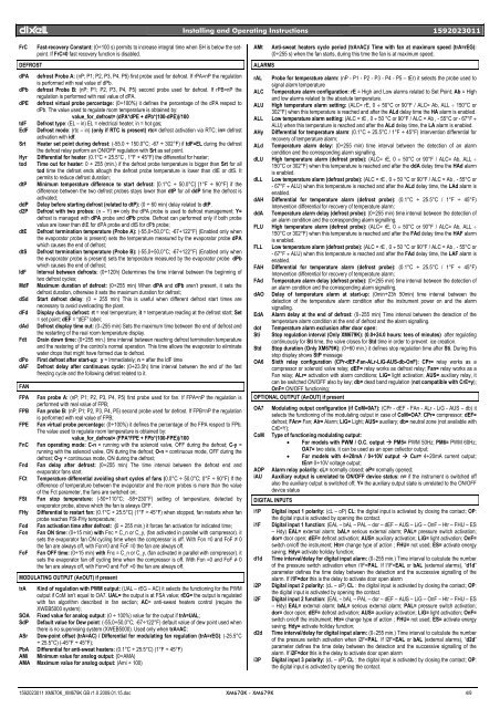
dIXEL Installing and Operating Instructions 1592023011FrCDEFROSTFast-recovery Constant: (0÷100 s) permits to increase integral time when SH is below the setpoint.If FrC=0 fast recovery function is disabled.dPA defrost Probe A: (nP; P1; P2, P3, P4, P5) first probe used for defrost. If rPA=nP the regulationis performed with real value of dPb.dPb defrost Probe B: (nP; P1; P2, P3, P4, P5) second probe used for defrost. If rPB=nP theregulation is performed with real value of dPA.dPE defrost virtual probe percentage: (0÷100%) it defines the percentage of the dPA respect todPb. The value used to regulate room temperature is obtained by:value_for_defrost= (dPA*dPE + dPb*(100-dPE))/100tdF Defrost type: (EL – in) EL = electrical heater; in = hot gas;EdF Defrost mode: (rtc – in) (only if RTC is present) rtc= defrost activation via RTC; in= defrostactivation with idf.Srt Heater set point during defrost: (-55.0 ÷ 150.0°C; -67 ÷ 302°F) if tdF=EL during the defrostthe defrost relay perform an ON/OFF regulation with Srt as set point.Hyr Differential for heater: (0.1°C ÷ 25.5°C , 1°F ÷ 45°F) the differential for heater;tod Time out for heater: 0 ÷ 255 (min.) if the defrost probe temperature is bigger than Srt for alltod time the defrost ends altough the defrost probe temperature is lower than dtE or dtS. Itpermits to reduce defrost duration;dtP Minimum temperature difference to start defrost: [0.1°C ÷ 50.0°C] [1°F ÷ 90°F] if thedifference between the two defrost probes stays lower than dtP for all ddP time the defrost isactivated;ddP Delay before starting defrost (related to dtP): (0 ÷ 60 min) delay related to dtP.d2P Defrost with two probes: (n – Y) n= only the dPA probe is used to defrost management; Y=defrost is managed with dPA probe and dPb probe. Defrost can performed only if both probevalue are lower than dtE for dPA probe and dtS for dPb probe;dtE Defrost termination temperature (Probe A): (-55,0÷50,0°C; -67÷122°F) (Enabled only whenthe evaporator probe is present) sets the temperature measured by the evaporator probe dPAwhich causes the end of defrost;dtS Defrost termination temperature (Probe B): (-55,0÷50,0°C; -67÷122°F) (Enabled only whenthe evaporator probe is present) sets the temperature measured by the evaporator probe dPbwhich causes the end of defrost;IdF Interval between defrosts: (0÷120h) Determines the time interval between the beginning oftwo defrost cycles;MdF Maximum duration of defrost: (0÷255 min) When dPA and dPb aren’t present, it sets thedefrost duration, otherwise it sets the maximum duration for defrost;dSd Start defrost delay: (0 ÷ 255 min) This is useful when different defrost start times arenecessary to avoid overloading the plant.dFd Display during defrost: rt = real temperature; it = temperature reading at the defrost start; Set= set point; dEF = “dEF” label;dAd Defrost display time out: (0÷255 min) Sets the maximum time between the end of defrost andthe restarting of the real room temperature display.Fdt Drain down time: (0÷255 min.) time interval between reaching defrost termination temperatureand the restoring of the control’s normal operation. This time allows the evaporator to eliminatewater drops that might have formed due to defrost.dPo First defrost after start-up: y = Immediately; n = after the IdF timedAF Defrost delay after continuous cycle: (0÷23.5h) time interval between the end of the fastfreezing cycle and the following defrost related to it.FANFPA Fan probe A: (nP; P1; P2, P3, P4, P5) first probe used for fan. If FPA=nP the regulation isperformed with real value of FPB;FPB Fan probe B: (nP; P1; P2, P3, P4, P5) second probe used for defrost. If FPB=nP the regulationis performed with real value of FPB;FPE Fan virtual probe percentage: (0÷100%) it defines the percentage of the FPA respect to FPb.The value used to regulate room temperature is obtained by:value_for_defrost= (FPA*FPE + FPb*(100-FPE))/100FnC Fan operating mode: C-n = running with the solenoid valve, OFF during the defrost; C-y =running with the solenoid valve, ON during the defrost; O-n = continuous mode, OFF during thedefrost; O-y = continuous mode, ON during the defrost;Fnd Fan delay after defrost: (0÷255 min) The time interval between the defrost end andevaporator fans start.FCt Temperature differential avoiding short cycles of fans (0.0°C ÷ 50.0°C; 0°F ÷ 90°F) If thedifference of temperature between the evaporator and the room probes is more than the valueof the Fct parameter, the fans are switched on;FSt Fan stop temperature: (-50÷110°C; -58÷230°F) setting of temperature, detected byevaporator probe, above which the fan is always OFF.FHy Differential to restart fan: (0.1°C ÷ 25.5°C) (1°F ÷ 45°F) when stopped, fan restarts when fanprobe reaches FSt-FHy temperature;FodFonFoFFan activation time after defrost: (0 ÷ 255 min.) it forces fan activation for indicated time;Fan ON time: (0÷15 min) with Fnc = C_n or C_y, (fan activated in parallel with compressor). itsets the evaporator fan ON cycling time when the compressor is off. With Fon =0 and FoF ≠ 0the fan are always off, with Fon=0 and FoF =0 the fan are always off.Fan OFF time: (0÷15 min) with Fnc = C_n or C_y, (fan activated in parallel with compressor). itsets the evaporator fan off cycling time when the compressor is off. With Fon =0 and FoF ≠ 0the fan are always off, with Fon=0 and FoF =0 the fan are always off.MODULATING OUTPUT (AnOUT) if presenttrA Kind of regulation with PWM output: (UAL – rEG – AC) it selects the functioning for the PWMoutput if CoM isn’t equal to OA7. UAL= the output is at FSA value; rEG= the output is regulatedwith fan algorithm described in fan section; AC= anti-sweat heaters control (require theXWEB5000 system);SOA Fixed value for analog output: (0 ÷ 100%) value for the output if trA=UAL;SdP Default value for Dew point: (-55,0÷50,0°C; -67÷122°F) default value of dew point used whenthere is no supervising system (XWEB5000). Used only when trA=AC;ASr Dew-point offset (trA=AC) / Differential for modulating fan regulation (trA=rEG): (-25.5°C÷ 25.5°C) (-45°F ÷ 45°F);PbA Differential for anti-sweat heaters: (0.1°C ÷ 25.5°C) (1°F ÷ 45°F)AMi Minimum value for analog output: (0÷AMA)AMA Maximum value for analog output: (Ami ÷ 100)AMtALARMSAnti-sweat heaters cycle period (trA=AC)/ Time with fan at maximum speed (trA=rEG):(0÷255 s) when the fan starts, during this time the fan is at maximum speed;rAL Probe for temperature alarm: (nP - P1 - P2 - P3 - P4 - P5 – tEr) it selects the probe used tosignal alarm temperatureALC Temperature alarm configuration: rE = High and Low alarms related to Set Point; Ab = Highand low alarms related to the absolute temperature.ALU High temperature alarm setting: (ALC= rE, 0 ÷ 50°C or 90°F / ALC= Ab, ALL ÷ 150°C or302°F) when this temperature is reached and after the ALd delay time the HA alarm is enabled.ALL Low temperature alarm setting: (ALC = rE , 0 ÷ 50 °C or 90°F / ALC = Ab , - 55°C or - 67°F ÷ALU) when this temperature is reached and after the ALd delay time, the LA alarm is enabled.AHy Differential for temperature alarm: (0.1°C ÷ 25.5°C / 1°F ÷ 45°F) Intervention differential forrecovery of temperature alarm;ALd Temperature alarm delay: (0÷255 min) time interval between the detection of an alarmcondition and the corresponding alarm signalling.dLU High temperature alarm (defrost probe): (ALC= rE, 0 ÷ 50°C or 90°F / ALC= Ab, ALL ÷150°C or 302°F) when this temperature is reached and after the ddA delay time the HAd alarmis enabled.dLL Low temperature alarm (defrost probe): (ALC = rE , 0 ÷ 50 °C or 90°F / ALC = Ab , - 55°C or- 67°F ÷ ALU) when this temperature is reached and after the ALd delay time, the LAd alarm isenabled.dAH Differential for temperature alarm (defrost probe): (0.1°C ÷ 25.5°C / 1°F ÷ 45°F)ddAIntervention differential for recovery of temperature alarm;Temperature alarm delay (defrost probe): (0÷255 min) time interval between the detection ofan alarm condition and the corresponding alarm signalling.FLU High temperature alarm (defrost probe): (ALC= rE, 0 ÷ 50°C or 90°F / ALC= Ab, ALL ÷150°C or 302°F) when this temperature is reached and after the FAd delay time the HAF alarmis enabled.FLLFAHFAddAOEdAdotStiStdOA6Low temperature alarm (defrost probe): (ALC = rE , 0 ÷ 50 °C or 90°F / ALC = Ab , - 55°C or- 67°F ÷ ALU) when this temperature is reached and after the FAd delay time, the LAF alarm isenabled.Differential for temperature alarm (defrost probe): (0.1°C ÷ 25.5°C / 1°F ÷ 45°F)Intervention differential for recovery of temperature alarm;Temperature alarm delay (defrost probe): (0÷255 min) time interval between the detection ofan alarm condition and the corresponding alarm signalling.Delay of temperature alarm at start-up: (0min÷23h 50min) time interval between thedetection of the temperature alarm condition after the instrument power on and the alarmsignalling.Alarm delay at the end of defrost: (0÷255 min) Time interval between the detection of thetemperature alarm condition at the end of defrost and the alarm signalling.Temperature alarm exclusion after door open:Stop regulation interval (Only <strong>XM679K</strong>): (0.0÷24.0 hours: tens of minutes) after regulatingcontinuously for Sti time, the valve closes for Std time in order to prevent ice creation.Stop duration (Only <strong>XM679K</strong>): (0÷60 min.) it defines stop regulation time after Sti. During thisstop display shows StP messageSixth relay configuration (CPr-dEF-Fan-ALr-LiG-AUS-db-OnF): CPr= relay works as acompressor or solenoid valve relay; dEF= relay works as defrost relay; Fan= relay works as aFan relay; ALr= activation with alarm conditions; LiG= light activation; AUS= auxiliary relay, itcan be switched ON/OFF also by key; db= dead band regulation (not compatible with CrE=y);OnF= ON/OFF functioning;OPTIONAL OUTPUT (AnOUT) if presentOA7 Modulating output configuration (if CoM=0A7): (CPr - dEF - FAn - ALr - LiG - AUS – db) itselects the functioning of the modulating output in case of CoM=OA7: CPr= compressor; dEF=defrost; FAn= Fan; Alr= Alarm; LiG= Light; AUS= auxiliary; db= neutral zone (not available withCrE=Y);CoM Type of functioning modulating output:• For models with PWM / O.C. output PM5= PWM 50Hz; PM6= PWM 60Hz;OA7= two state, it can be used as an open collector output;• For models with 4÷20mA / 0÷10V output Cur= 4÷20mA current output;tEn= 0÷10V voltage output;AOP Alarm relay polarity: cL= normally closed; oP= normally opened;iAU Auxiliary output is unrelated to ON/OFF device status: n= if the instrument is switched offalso the auxiliary output is switched off; Y= the auxiliary output state is unrelated to the ON/OFFdevice statusDIGITAL INPUTSi1Pi1Fd1di2Pi2Fd2di3PDigital input 1 polarity: (cL – oP) CL: the digital input is activated by closing the contact; OP:the digital input is activated by opening the contact.Digital input 1 function: (EAL – bAL – PAL – dor – dEF – AUS – LiG – OnF – Htr – FHU – ES– Hdy) EAL= external alarm; bAL= serious external alarm; PAL= pressure switch activation;dor= door open; dEF= defrost activation; AUS= auxiliary activation; LiG= light activation; OnF=switch on/off the instrument; Htr= change type of action ; FHU= not used; ES= activate energysaving; Hdy= activate holiday function;Time interval/delay for digital input alarm: (0÷255 min.) Time interval to calculate the numberof the pressure switch activation when i1F=PAL. If I1F=EAL or bAL (external alarms), “d1d”parameter defines the time delay between the detection and the successive signalling of thealarm. If i1F=dor this is the delay to activate door open alarmDigital input 2 polarity: (cL – oP) CL : the digital input is activated by closing the contact; OP:the digital input is activated by opening the contact.Digital input 2 function: (EAL – bAL – PAL – dor – dEF – AUS – LiG – OnF – Htr – FHU – ES– Hdy) EAL= external alarm; bAL= serious external alarm; PAL= pressure switch activation;dor= door open; dEF= defrost activation; AUS= auxiliary activation; LiG= light activation; OnF=switch on/off the instrument; Htr= change type of action ; FHU= not used; ES= activate energysaving; Hdy= activate holiday function;Time interval/delay for digital input alarm: (0÷255 min.) Time interval to calculate the numberof the pressure switch activation when i2F=PAL. If I2F=EAL or bAL (external alarms), “d2d”parameter defines the time delay between the detection and the successive signalling of thealarm. If i2F=dor this is the delay to activate door open alarmDigital input 3 polarity: (cL – oP) CL : the digital input is activated by closing the contact; OP:the digital input is activated by opening the contact.1592023011 <strong>XM670K</strong>_<strong>XM679K</strong> GB r1.0 2009.01.15.doc <strong>XM670K</strong> - <strong>XM679K</strong> 4/9


