XM670K- XM679K - Copyright Arctica Oy
XM670K- XM679K - Copyright Arctica Oy
XM670K- XM679K - Copyright Arctica Oy
- No tags were found...

Create successful ePaper yourself
Turn your PDF publications into a flip-book with our unique Google optimized e-Paper software.
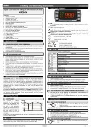
dIXEL Installing and Operating Instructions 159202301115.1 “EE” ALARMThe dIXEL instruments are provided with an internal check for the data integrity. Alarm “EE” flasheswhen a failure in the memory data occurs. In such cases the alarm output is enabled.15.2 ALARM RECOVERY12. ELECTRICAL CONNECTIONS<strong>XM670K</strong>/<strong>XM679K</strong> is provided with screw terminal block to connect cables with a cross section up to 1,6mm 2 for all the low voltage connection: the RS485, the LAN, the probes, the digital inputs and thekeyboard. Other inputs, power supply and relays connections are provided with Faston connection (5.0mm). Heat-resistant cables have to be used. Before connecting cables make sure the power supplycomplies with the instrument’s requirements. Separate the probe cables from the power supply cables,from the outputs and the power connections. Do not exceed the maximum current allowed on eachrelay, in case of heavier loads use a suitable external relay. N.B. Maximum current allowed for all theloads is 16A.12.1 PROBE CONNECTIONSThe probes shall be mounted with the bulb upwards to prevent damages due to casual liquid infiltration.It is recommended to place the thermostat probe away from air streams to correctly measure theaverage room temperature. Place the defrost termination probe among the evaporator fins in the coldestplace, where most ice is formed, far from heaters or from the warmest place during defrost, to preventpremature defrost termination.13. RS485 SERIAL LINE<strong>XM670K</strong>/<strong>XM679K</strong> is provided of a direct RS485 connection that allow the unit, to be linked to a networkline ModBUS-RTU compatible with all dIXEL monitoring system.14. USE OF THE PROGRAMMING “HOT KEY“The XM units can UPLOAD or DOWNLOAD the parameter list from its own E2 internal memory to the“Hot Key” and vice-versa through a TTL connector.14.1 DOWNLOAD (FROM THE “HOT KEY” TO THE INSTRUMENT)1. Turn OFF the instrument by means of the ON/OFF key ,insert the “Hot Key” and then turn theunit ON.2. Automatically the parameter list of the “Hot Key” is downloaded into the controller memory, the“doL” message is blinking. After 10 seconds the instrument will restart working with the newparameters. At the end of the data transfer phase the instrument displays the followingmessages: “end“ for right programming. The instrument starts regularly with the newprogramming. “err” for failed programming. In this case turn the unit off and then on if you wantto restart the download again or remove the “Hot key” to abort the operation.14.2 UPLOAD (FROM THE INSTRUMENT TO THE “HOT KEY”)1. When the XM unit is ON, insert the “Hot key” and push è key; the "uPL" message appears.2. The UPLOAD begins; the “uPL” message is blinking.3. Remove the “Hot Key”.At the end of the data transfer phase the instrument displays the following messages:“end “ for right programming.“err” for failed programming. In this case push “SET” key if you want to restart the programmingagain or remove the not programmed “Hot key”.15. ALARM SIGNALSMessage Cause Outputs“PON” Keyboard enabled Outputs unchanged“POF” Keyboard locked Outputs unchanged“rst” Alarm reset Alarm relay reset“nOP” probe not present Compressor output acc. to par. “Con” and “COF”“P1” First probe failure Compressor output acc. to par. “Con” and “COF”“P2” Second probe failure Defrost end is timed“P3” Third probe failure Outputs unchanged“P4” Fourth probe failure Outputs unchanged“P5” Fifth probe failure Outputs unchanged“P6” Sixth probe failure Outputs unchanged“HA” Maximum temperature alarm Outputs unchanged.“LA” Minimum temperature alarm Outputs unchanged."HAd Defrost high temperature Outputs unchanged."LAd” Defrost low temperature Outputs unchanged."FAd” Defrost low temperature Outputs unchanged."HAF” Fan high temperature Outputs unchanged."LAF” Fan high temperature Outputs unchanged."StP” Stop due to regulation pauses (Sti and Compressor and valve OFFStd parameters)“PAL” Lock due to pressure switch All outputs OFF.“rtc” RTC wrongly configured Outputs unchanged“rtf” RTC failure Outputs unchanged“dA” Door open Compressor and fans restarts according to rrd andodc“EA” External alarm Output unchanged.“CA” Serious external alarm (i1F=bAL) All outputs OFF.“EE” EEPROM failure All outputs OFF.“LOP” Minimum operating pressure reached according to dML“MOP” Maximum operating pressure reached according to dML“LSH” Minimum superheat alarm Valve closed“MSH” Maximum superheat alarm outputs unchangedProbe alarms : “P1” (probe1 faulty), “P2”, “P3”, “P4”, “P5”, “P6”; they automatically stop 10s after theprobe restarts normal operation. Check connections before replacing the probe. Temperature alarms“HA”, “LA”, “HAd”, “LAd”, “HAF”, “LAF” automatically stop as soon as the thermostat temperaturereturns to normal values or when the defrost starts. External alarms “EAL”, “BAL” stop as soon as theexternal digital input is disabled.16. TECHNICAL DATACX660 keyboardHousing: self extinguishing ABS.Case: CX660 facia 35x77 mm; depth 18mmMounting: panel mounting in a 29x71 mm panel cut-outProtection: IP20; Frontal protection: IP65Power supply: from XM600K power moduleDisplay: 3 digits, red LED, 14,2 mm high;Optional output: buzzerPower modulesCase: 8 DINConnections: Screw terminal block ≤ 1,6 mm 2 heat-resistant wiring and 5.0mm FastonPower supply: depending on the model 12Vac – 24Vac - 110Vac ± 10% - 230Vac ± 10% or90÷230Vac with switching power supply.Power absorption: 9VA max.Inputs: up to 6 NTC/PTC/Pt1000 probesDigital inputs: 3 free of voltageRelay outputs: Total current on loads MAX. 16ASolenoid Valve: relay SPST 5(3) A, 250Vacdefrost: relay SPST 16 A, 250Vacfan: relay SPST 8 A, 250Vaclight: relay SPST 16 A, 250Vacalarm: SPDT relay 8 A, 250VacAux: SPST relay 8 A, 250VacValve output: a.c. output up to 30W (Only <strong>XM679K</strong>)Optional output (AnOUT) DEPENDING ON THE MODELS:• PWM / Open Collector outputs: PWM or 12Vdc max 40mA• Analog output: 4÷20mA or 0÷10VSerial output: RS485 with ModBUS - RTU and LANData storing: on the non-volatile memory (EEPROM).Kind of action: 1B. Pollution grade: normal Software class: A. Operating temperature: 0÷60 °C.Storage temperature: -25÷60 °C. Relative humidity: 20÷85% (no condensing).Measuring and regulation range:NTC probe: -40÷110°C (-58÷230°F).PTC probe: -50÷150°C (-67 ÷ 302°F)Pt1000 probe: -100 ÷ 100°C (-148 ÷ 212°F)Resolution: 0,1 °C or 1°C or 1 °F (selectable). Accuracy (ambient temp. 25°C): ±0,5 °C ±1 digit17. CONNECTIONS17.1 <strong>XM670K</strong> – ALL POWER SUPPLY17.2 <strong>XM679K</strong> – 230VAC VALVES1592023011 <strong>XM670K</strong>_<strong>XM679K</strong> GB r1.0 2009.01.15.doc <strong>XM670K</strong> - <strong>XM679K</strong> 6/9