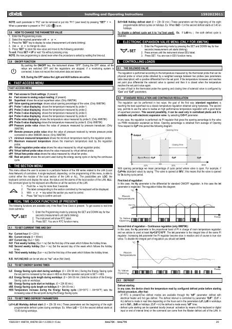
dIXEL Installing and Operating Instructions 1592023011NOTE: each parameter in “Pr2” can be removed or put into “Pr1” (user level) by pressing “SET” + n.When a parameter is present in “Pr1” LED is on.3.8 HOW TO CHANGE THE PARAMETER VALUE1. Enter the Programming mode.2. Select the required parameter with o or n.3. Press the “SET” key to display its value (measurement unit starts blinking).4. Use o or n to change its value.5. Press “SET” to store the new value and move to the following parameter.To exit: Press SET + UP or wait 15s without pressing a key.NOTE: the new programming is stored even when the procedure is exited by waiting the time-out.3.9 ON/OFF FUNCTIONBy pushing the ON/OFF key, the instrument shows “OFF”. During the OFF status, all therelays are switched OFF and the regulations are stopped; if a monitoring system isconnected, it does not record the instrument data and alarms.N.B. During the OFF status the Light and AUX buttons are active.4. FAST ACCESS MENUFAST ACCESS MENUHM Fast access to Clock settings; (if present)An Fast access to analog output reading; (if present)SH Superheat: shows the actual superheat value; (Only <strong>XM679K</strong>)oPP Valve opening percentage: shows actual opening percentage of the valve; (Only <strong>XM679K</strong>)dP1 Probe 1 value displaying shows the temperature measured by probe 1;dP2 Probe 2 value displaying shows the temperature measured by probe 2;dP3 Probe 3 value displaying shows the temperature measured by probe 3;dp4 Probe 4 value displaying shows the temperature measured by probe 4;dP5 Probe value displaying shows the temperature value measured by probe 5; (Only <strong>XM679K</strong>)dP6 Probe 6 value displaying shows the temperature measured by probe 6; (Only <strong>XM679K</strong>)dPP Pressure probe value shows the value of pressure measured by pressure transducer; (Only<strong>XM679K</strong>)rPP Remote pressure probe value show the value of pressure received by remote pressure probeconnected to other XM600K device; (Only <strong>XM679K</strong>)L°t minimum measured temperature shows the minimum temperature read by the regulation probe;H°t Maximum measured temperature shows the maximum temperature read by the regulationprobe;dPr Virtual regulation probe value shows the value measured by virtual regulation probe;dPd Virtual defrost probe value shows the value measured by virtual defrost probe;dPF Virtual fans probe value shows the value measured by virtual fan probe;rSE Real set point: shows the set point used during the energy saving cycle or during the continuouscycle.5. THE SECTION MENUThis menu allows the user to access to a particular feature of the XM series related to the LAN (LocalArea Network) of controllers. A single keyboard, depending on the programming of this menu, is able tocontrol either the module of the local section of the LAN or ALL. The possibilities are: LOC: thekeyboard controls and display the value, the status and the alarms of the local section of the LAN; ALL:the command given by the keyboard are effective on all the sections of the LAN.1. Push the o key for more than 3 seconds2. The label corresponding to the section controlled by the keyboard will be displayed.3. With o or n key select the section you want to control.4. Press “Set” key to confirm and exit6. REAL TIME CLOCK FUNCTIONS (IF PRESENT)The following functions are available only if the Real Time Clock is present. To get access to real timeclock submenu:1. Enter the Programming mode by pressing the SET and DOWN key for fewseconds (measurement unit starts blinking).+ SET2. The instrument will show RTC label;3. Press SET. You are in RTC function menu;6.1 TO SET CURRENT TIME AND DAYHur Current hour (0 ÷ 23 h)Min Current minute (0 ÷ 59min)dAY Current day (Sun ÷ SAt)Hd1 First weekly holiday (Sun ÷ nu) Set the first day of the week which follows the holiday times.Hd2 Second weekly holiday (Sun ÷ nu) Set the second day of the week which follows the holidaytimes.Hd3 Third weekly holiday (Sun ÷ nu) Set the third day of the week which follows the holiday times.Sd1÷Sd6 Holiday defrost start (0 ÷ 23h 50 min.) These parameters set the beginning of the eightprogrammable defrost cycles on holidays. Ex. When Sd2 = 3.4 the second defrost starts at 3.40 onholidays.To disable a defrost cycle set it to “nu”(not used). Ex. If Ld6=nu ; the sixth defrost cycle isdisabled7. ELECTRONIC EXPANSION VALVE MENU (ONLY FOR <strong>XM679K</strong>)1. Enter the Programming mode by pressing the SET and DOWN key for fewseconds (measurement unit starts blinking).+ SET2. Press arrows until the instrument shows EEU label;3. Press SET. You are now in EEV function menu;8. CONTROLLING LOADS8.1 THE SOLENOID VALVEThe regulation is performed according to the temperature measured by the thermostat probe that can bephysical probe or virtual probe obtained by a weighted average between two probes (see parameterstable description) with a positive differential from the set point. If the temperature increases and reachesset point plus differential the solenoid valve is opened and then it is closed when the temperaturereaches the set point value again.In case of fault in the thermostat probe the opening and closing time of solenoid valve is configured by“Con” and “CoF” parameters.8.2 STANDARD REGULATION AND CONTINUOUS REGULATIONThe regulation can be performed in two ways: the goal of the first way (standard regulation) isreaching the best superheat via a classic temperature regulation obtained using hysteresis. The secondway, permits to use the valve to realise an high performance temperature regulation with a good factorof superheat precision. This second possibility, it can be used only in centralized plants and it isavailable only with electronic expansion valve by selecting CrE=Y parameter.In any case, the regulation is performed via PI regulator that gives the opening percentage to the valvevia PWM modulation explained as follow. Opening percentage is obtained from average of OpeningTime respect to CyP time period like following diagram:With opening percentage we mean percentage of cycle period where valve is open. For example, ifCyP=6s (standard value) by saying: “The valve is opened at 50%”; this means that the valve is openedfor 3s during cycle period.First kind of regulation:In this case, the Hy parameter is the differential for standard ON/OFF regulation. In this case the intparameter is neglected. The regulation follow this diagram:Second kind of regulation – Continuous regulation (only <strong>XM679K</strong>):In this case, the Hy parameter is the proportional band of PI in charge of room temperature regulationand we advise to used at least Hy=5.0°C/10°F. The int parameter is the integral time of the same PIregulator. Increasing int parameter the PI regulator become slow in reaction and of course is true viceversa. To disable the integral part of regulation you should set int=0.N.B. Hd1,Hd2,Hd3 can be set also as “nu” value (Not Used).6.2 TO SET ENERGY SAVING TIMESILE Energy Saving cycle start during workdays: (0 ÷ 23h 50 min.) During the Energy Saving cyclethe set point is increased by the value in HES so that the operation set point is SET + HES.dLE Energy Saving cycle length during workdays: (0 ÷ 24h 00 min.) Sets the duration of the EnergySaving cycle on workdays.ISE Energy Saving cycle start on holidays. (0 ÷ 23h 50 min.)dSE Energy Saving cycle length on holidays (0 ÷ 24h 00 min.)HES Temperature increase during the Energy Saving cycle (-30÷30°C / -54÷54°F) sets theincreasing value of the set point during the Energy Saving cycle.6.3 TO SET TIMED DEFROST PARAMETERSLd1÷Ld6 Workday defrost start (0 ÷ 23h 50 min.) These parameters set the beginning of the eightprogrammable defrost cycles during workdays. Ex. When Ld2 = 12.4 the second defrost starts at12.40 during workdays.8.3 DEFROSTDefrost startingIn any case, the device check the temperature read by configured defrost probe before startingdefrost procedure, after that:- (If RTC is present)Two defrost modes are available through the “tdF” parameter: defrost withelectrical heater and hot gas defrost. The defrost interval is controlled by parameter “EdF”: (EdF =rtc) defrost is made in real time depending on the hours set in the parameters Ld1..Ld6 in workdaysand in Sd1…Sd6 on holidays; (EdF = in) the defrost is made every “IdF” time;- defrost cycle starting can be operated locally (manual activation by means of the keyboard or digitalinput or end of interval time) or the command can come from the Master defrost unit of the LAN. In1592023011 <strong>XM670K</strong>_<strong>XM679K</strong> GB r1.0 2009.01.15.doc <strong>XM670K</strong> - <strong>XM679K</strong> 2/9
dIXEL Installing and Operating Instructions 1592023011this case the controller will operate the defrost cycle following the parameters it has programmed but,at the end of the drip time, will wait that all the other controllers of the LAN finish their defrost cyclebefore to re-start the normal regulation of the temperature according to dEM parameter;- Every time any of the controller of the LAN begin a defrost cycle it issue the command into thenetwork making all the other controllers start their own cycle. This allows a perfect synchronisation ofthe defrost in the whole multiplexed cabinet according to LMd parameter;- Selecting dPA and dPb probes and by changing the dtP and ddP parameters the defrost can bestarted when the difference between dPA and dPb probes is lower than dtP for all ddP time. This isuseful to start defrost when a low thermal exchange is detected. If ddP=0 this function is disabled;Defrost ending- When defrost is started via rtc, the maximum duration of defrost is obtained from Md parameter andthe defrost end temperature is obtained from dtE parameter (and dtS if two defrost probes areselected).- If dPA and dPb are present and d2P=y the instrument stops the defrost procedure when dPA ishigher than dtE temperature and dPb is higher than dtS temperature;At the end of defrost the drip time is controlled through the “Fdt” parameter.8.4 FANSCONTROL WITH RELAYThe fan control mode is selected by means of the “FnC” parameter:C-n = running with the solenoid valve, OFF during the defrost;C-y = running with th1e solenoid valve, ON during the defrost;O-n = continuous mode, OFF during the defrost;O-y = continuous mode, ON during the defrost;An additional parameter “FSt” provides the setting of temperature, detected by the evaporator probe,above which the fans are always OFF. This can be used to make sure circulation of air only if histemperature is lower than set in “FSt”.CONTROL WITH ANALOG OUTPUT (if present)8.5 ANTI SWEAT HEATERS (IF PRESENT)The modulating output (trA=rEG) works inproportional way (excluding the first AMtseconds where the fans speed is the maximum).The regulation set point is relative to regulationset point and is indicated by ASr, theproportional band is always located aboveSET+ASr value and its value is PbA. The fan areat minimum speed (AMi) when the temperatureread by fan probe is SET+ASr and the fan is atmaximum speed (AMA) when the temperature isSET+ASr+PbA.This control is performed when trA=AC. In this case, there is two way to control the anti-sweat heaters:• Without real dew-point information: in this case the default value for dew-point is used(SdP parameter).• Receiving dew-point from XWEB5000 system: the SdP parameter is overwrote when validvalue for dew-point is received from XWEB.8.6 AUXILIARY OUTPUTThe P4 probe is used to perform the regulationand it should be placed on the showcase glass.In case of P4 error or if P4 is absent the output isat AMA value for the AMt time then the output isat 0 value for the time 255-AMt time performinga simple PWM modulation.The auxiliary output is switch ON and OFF by means of the corresponding digital input or by pressingand releasing the down arrow key.9. PARAMETER LISTREGULATIONrtC Access to CLOCK submenu (if present);EEU Access to EEV submenu (only <strong>XM679K</strong>);Hy Differential: (0,1÷25,5°C; 1÷45°F): Intervention differential for set point, always positive.Solenoid valve Cut IN is Set Point Plus Differential (Hy). Solenoid valve Cut OUT is when thetemperature reaches the set point.Int Integral time for room temperature regulation (Only <strong>XM679K</strong>): (0 ÷ 255 s) integral time forroom temperature PI regulator. 0= no integral action;CrE Continuous regulation activation (Only <strong>XM679K</strong>): (n÷Y) n= standard regulation; Y=continuous regulation. Use it only in centralized plants;LS Minimum set point limit: (-55.0°C÷SET; -67°F÷SET) Sets the minimum acceptable value forthe set point.US Maximum set point limit: (SET÷150°C; SET÷302°F) Set the maximum acceptable value forset point.OdS Outputs activation delay at start up: (0÷255 min) This function is enabled at the initial startup of the instrument and inhibits any output activation for the period of time set in theparameter. (AUX and Light can work)AC Anti-short cycle delay: (0÷60 min) interval between the solenoid valve stop and the followingrestart.CCt Compressor ON time during continuous cycle: (0.0÷24.0h; resolution 10min) Allows to setthe length of the continuous cycle: compressor stays on without interruption for the CCt time.Can be used, for instance, when the room is filled with new products.CCS Set point for continuous cycle: (-55÷150°C / -67÷302°F) it sets the set point used during thecontinuous cycle.ConCoFDISPLAYCFPrUPMUPMdrESLodreddLyrPArPbrPEsolenoid valve ON time with faulty probe: (0÷255 min) time during which the solenoid valveis active in case of faulty thermostat probe. With COn=0 solenoid valve is always OFF.solenoid valve OFF time with faulty probe: (0÷255 min) time during which the solenoid valveis off in case of faulty thermostat probe. With COF=0 solenoid valve is always active.Temperature measurement unit: °C=Celsius; °F=Fahrenheit. !!! WARNING !!! When themeasurement unit is changed the parameters with temperature values have to be checked.Pressure mode: (rEL or AbS) it defines the mode to use the pressure. !!! WARNING !!! thesetting of PrU is used for all the pressure parameters. If PrU=rEL all pressure parameters are inrelative pressure unit, if PrU=AbS all pressure parameters are in absolute pressure unit. (Only<strong>XM679K</strong>)Pressure measurement unit: (bAr – PSI - MPA) it selects the pressure measurement units.MPA= the value of pressure measured by kPA*10. (Only <strong>XM679K</strong>)Way of displaying pressure : (tEM - PrE) it permits showing the value measured by pressureprobe with tEM= temperature or by PrE= pressure; (Only <strong>XM679K</strong>)Resolution (for °C): (in = 1°C; dE = 0.1 °C) allows decimal point display;Instrument display: (nP; P1; P2, P3, P4, P5, P6, tEr, dEF) it selects which probe is displayedby the instrument. P1, P2, P3, P4, P5, P6, tEr= virtual probe for thermostat, dEF= virtual probefor defrost.Remote display: (nP; P1; P2, P3, P4, P5, P6, tEr, dEF) it selects which probe is displayed bythe X-REP. P1, P2, P3, P4, P5, P6, tEr= virtual probe for thermostat, dEF= virtual probe fordefrost.Display delay: (0 ÷24.0 m; resolution 10s) when the temperature increases, the display isupdated of 1 °C/1°F after this time.Regulation probe A: (nP; P1; P2, P3, P4, P5) first probe used to regulate room temperature. IfrPA=nP the regulation is performed with real value of rPb.Regulation probe B: (nP; P1; P2, P3, P4, P5) second probe used to regulate roomtemperature. If rPb=nP the regulation is performed with real value of rPARegulation virtual probe percentage: (0 ÷ 100%) it defines the percentage of the rPA respectto rPb. The value used to regulate room temperature is obtained by:value_for_room = (rPA*rPE + rPb*(100-rPE))/100ELECTRONIC EXPANSION VALVE SUBMENU (Only <strong>XM679K</strong>)FtY Kind of gas (R22, 134, 404, 407, 410, 507,CO2): Type of gas used by plant. Fundamentalparameter for correct functioning of all system.SSH Superheat set point: [0.1°C ÷ 25.5°C] [1°F ÷ 45°F] it’s the value used to regulate superheatCyP Cycle Period: (1 ÷ 15s) it permits to set cycle time;Pb Proportional band: (0.1 ÷ 60.0 / 1÷108°F) PI proportional band;rS Band Offset: (-12.0 ÷ 12.0°C / -21÷21°F) PI band offset;inC Integration time: (0 ÷ 255s) PI integration time;PEO Probe Error opening percentage: (0÷100%) if a temporary probe error occurs, valve openingpercentage is PEo until PEd time is elapsed;PEd Probe Error delay before stopping regulation: (0÷239 sec. – On=unlimited) if probe errorduration is bigger than PEd then valve totally closes. Pf message is showed. If PEd=On valveopening is PEo until probe error finishes;OPE Start opening Percentage: (0÷100%) Opening valve percentage when start function is active.This phase duration is SFd time;SFd Start Function duration: (0.0 ÷ 42.0 min: resolution 10s) It sets start function duration andpost-defrost duration. During this phase the alarms are neglected;OPd Opening Percentage after defrost phase: (0÷100%) Opening valve percentage when afterdefrost function is active. This phase duration is Pdd time;Pdd Post Defrost Function duration: (0.0 ÷ 42.0 min: resolution 10s) It sets start function durationand post-defrost duration. During this phase the alarms are neglected;MnF Maximum opening percentage at normal Functioning: (0÷100%) during regulation it setsthe maximum valve opening percentage;dCL Delay before stopping valve regulation: (0 ÷ 255s) When the cooling request goes off, theelectronic valve regulation can go on for the dCL time in order to prevent uncontrolledsuperheat variation;Fot Forced opening percentage: (0÷100% - nu) it permits to force the valve opening to thespecified value. This value overwrite the value calculated by PID algorithm. !!!! WARNING !!!!to obtain the correct superheat regulation you have to set Fot=nu;tPP Type of Pressure Transducer: (PP – LAn) it sets type of pressure transducer to use: PP=4÷20mA pressure transducer or ratiometric transducer 0÷5V depending on P5C parameter,LAn= the pressure signal arrives from another XM600K; Referred to Pb5PA4 Probe value At 4mA or At 0V: (-1.0 ÷ P20 bar / -14 ÷ PSI / -10 ÷ P20 kPA*10) pressure valuemeasured by probe at 4mA or at 0V (related to PrM parameter) Referred to Pb5P20 Probe value 20mA or At 5V: (PA4 ÷ 50.0 bar / 725 psi / 500 kPA*10) pressure valuemeasured by probe at 20mA or at 5V (related to PrM parameter) Referred to Pb5LPL Lower Pressure Limit for superheat regulation: (PA4 ÷ P20 bar / psi / kPA*10) when suctionpressure comes down to LPL the regulation is performed with a LPL fixed value for pressure,when pressure comes back to LPL the normal pressure value is used. (related to PrMparameter)MOP Maximum Operating Pressure threshold: (PA4 ÷ P20 bar / psi / kPA*10) if suction pressureexceeds maximum operating pressure value, instrument signals situation with MOP alarm.(related to PrM parameter)LOP Lowest Operating Pressure threshold: (PA4 ÷ P20 bar / psi / kPA*10) if the suction pressurecomes down to this value a low pressure alarm is signalled with LOP alarm. (related to PrMparameter)dML delta MOP-LOP: (0 ÷ 100%) when a MOP alarm occurs valve will close of the dML percentageevery cycle period until MOP alarm is active. When LOP occurs valve will open of the dMLpercentage every cycle period until LOP alarm is active.MSH Maximum Superheat alarm: (LSH ÷ 80.0°C / LSH ÷ 144°F) when superheat exceeds thisvalue an high superheat alarm is signalled after interval SHdLSH Lowest Superheat alarm: (0.0 ÷ MSH °C / 0÷MSH °F) when superheat goes down to thisvalue a low superheat alarm is signalled after interval SHdSHy Superheat alarm Hysteresis: (0.1÷25.5°C/1÷45°F) hysteresis for superheat alarmSHddeactivationSuperheat alarm activation delay: (0.0 ÷ 42.0 min: resolution 10s) when a superheat alarmoccurs, the time SHd have to pass before signalling alarm;1592023011 <strong>XM670K</strong>_<strong>XM679K</strong> GB r1.0 2009.01.15.doc <strong>XM670K</strong> - <strong>XM679K</strong> 3/9