BOSCH GREENSTAR ZWBR 7-25 A23 GCNo.46-311-44 - AC Wilgar
BOSCH GREENSTAR ZWBR 7-25 A23 GCNo.46-311-44 - AC Wilgar
BOSCH GREENSTAR ZWBR 7-25 A23 GCNo.46-311-44 - AC Wilgar
- No tags were found...

Create successful ePaper yourself
Turn your PDF publications into a flip-book with our unique Google optimized e-Paper software.
<strong>GREENSTAR</strong>WALL MOUNTED CONDENSING BOILER FOR CENTRAL HEATINGAND MAINS FED DOMESTIC HOT WATERINSTALLATION ANDSERVICING INSTRUCTIONSCat II2H 3P applianceGC NUMBERSGreenstar <strong>ZWBR</strong> 7-<strong>25</strong> <strong>A23</strong> (N.G.) 47 <strong>311</strong> <strong>44</strong>Greenstar <strong>ZWBR</strong> 11-<strong>25</strong> A31 (L.P.G.) 47 <strong>311</strong> 45THIS APPLIANCE IS FOR USE ON SEALED PRIMARY SYSTEMS ONLYIMPORTANT: THESE INSTRUCTIONS APPLY IN THE UK ONLYTHESE INSTRUCTIONS ARE TO BE LEFT WITH THE USER OR AT THE GAS METERThis appliance must be installed by a competent person in accordancewith the Gas Safety (Installation and Use) Regulations 1998
Contents1. Installation Regulations .............................................. Page 22. Introduction.................................................................. Page 23. Technical Data .............................................................. Page 34. Siting the Appliance .................................................... Page 55. Flue Systems ................................................................ Page 56. Siting the Flue Terminal .............................................. Page 67. Gas Supply.................................................................... Page 68. Air Supply .................................................................... Page 79. Sealed System .............................................................. Page 710. Domestic Hot Water .................................................... Page 811. Electrical........................................................................ Page 812. Installation .................................................................... Page 1013. Commissioning ............................................................ Page 1514. Instructions to the User .............................................. Page 2115. Inspection and Servicing ............................................ Page 2116. Replacement of Parts .................................................. Page 2417. Short Parts List ............................................................ Page 2918. Operational Flow Diagrams........................................ Page 3019. Fault Finding ................................................................ Page 32Gas Safety (Installation & Use) Regulations 1998: All gasappliances must be installed by a competent person. Failure toinstall correctly could lead to prosecution.The manufacturers notes must not be taken, in any way, asoverriding statutory obligations.The appliance must be installed in accordance with the currentIEE Wiring Regulations, local Building Regulations, BuildingStandards (Scotland) (Consolidation), bye-laws of the local WaterCompany, Health and Safety Document 635 (Electricity at WorkRegulations 1989) and any other local requirements.Product Liability regulations indicate that, in certaincircumstances, the installer can be held responsible, not only formistakes on his part but also for damage resulting from the useof faulty materials. We advise the installer to avoid any risk byusing only quality approved branded fittings.The relevant British Standards should be followed i.e.BS 6798 Specification for the installation of gas fired hot waterboilers of rated input not exceeding 60kWBS 5<strong>44</strong>9BS 5546Central Heating for Domestic PremisesInstallation of gas hot water supplies for domesticpurposesBS 5<strong>44</strong>0:1 Flues and ventilation for gas appliances of rated inputnot exceeding 60kW: FluesBS 5<strong>44</strong>0:2 Flues and ventilation for gas appliances of rated inputnot exceeding 60kW: Air SupplyBS 68911. Installation RegulationsInstallation of low pressure gas pipeworkinstallations up to 28mm (R1).BS 7074:1 Code of practice for domestic heating and hot watersupply.These instructions must be followed.2. IntroductionThe appliance output of <strong>25</strong>.3kW in the condensing mode isavailable for the heating system and up to 23.5kW for thedomestic hot water with the domestic hot water having thepriority. An automatic hot water pre-heat facility is available togive an almost instant supply of hot water at the tap or shower.The appliance is supplied for use on a sealed system only and isnot suitable for external installation. It must be connected to agoverned metered gas supply. It is dispatched suitable for use onNatural Gas.It is a room sealed appliance and does not require a separatecombustion air supply – because of the low casing lossesventilation are not required when the appliance is installed in acupboard or compartment.Do not block the specified space left for servicing.An electrical supply failure will stop the appliance. Normaloperation will resume upon the restoration of the supply.A standard 100mm flue system is available for horizontal fluesupto 2m.Multi-directional flue systems are available up to 10m verticaland 8m horizontal. A twin-pipe system is available.An integral facia display shows the central heating flowtemperature or a fault condition of the appliance.Comprehensive safety features are standard as is an automaticignition system. The use of a pre-mixed burner gives a very lowNO x discharge level.Do not run the appliance in the waterless condition.The condensing mode gives very high efficiency figures whichcan be utilised fully by sizing the system to match thecondensing parameters i.e. low temperature radiators. Howeverthe appliance will operate at normal flow temperatures whenrequired to do so and still maintain high system efficiencies.To ensure that the appliance gives the best performance possibleit is recommended that an outside temperature compensator(Junkers TA211E) and a twin-channel digital programmer (JunkersEU2D) are fitted.Full installation and operating instructions are packed with thecontrols.Check that no dirt is left in either the gas or water pipework asthis could damage the appliance. Thoroughly flush the heatingsystem and mains water supply in accordance with therecommendations of BS 7593:1992.The heat exchanger is manufactured from aluminium and onlycompatible flushing agents shall be used.A link is provided to allow flushing of the system before theappliance is hung on the mounting manifold.Purge the gas supply before finally connecting the appliance.To ensure that the installation will perform to the higheststandards, the system and components should conform to anyother relevant British Standards in addition to those mentionedin the instructions.The boiler, when in use, will operate at high efficiency emitting awhite plume of condensation from the flue terminal.Positions that might cause a nuisance should be avoided.A condensate drain and syphon is provided on the appliance.Take special note of the requirements for the drainage ofcondensate.The advice and instructions in this document covers, as far aspossible, the forseeable situations which may arise. ContactWorcester Heat Systems for advice on specific installations.LPG InstallationThe appliance shall not be installed in a room or internal spacebelow ground level when it is intended to be used with LPG. Thisdoes not preclude the installation into rooms which arebasements with respect to one side of the building but open tothe ground on the opposite side.Asbestos or asbestos based products are not used on thisappliance nor in the manufacturing process.2
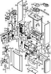
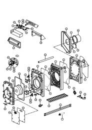
Fig. 1. Appliance water flow diagram.AutomaticAirVentCharging PointAutomaticAirVentWatertoWaterHeatExchangerExpansionVesselHeatExchangerSiphonDrainPumpPressure Relief ValveCondensateTrapDrainDiverterValveFlowSwitchCHFlowDomestic HotWater OutCondensate & ReliefValve DrainDomesticCold SupplyCHReturn3. Technical DataTable 1SETTINGMAXIMUMMINIMUMNOMINAL BOILER RATINGSFLOW RETURN OUTPUT INPUT GAS RATE-NGTEMPERATURE °C TEMPERATURE °C kW kW (Net) m 3 /h80 60 23.0 24.0 2.5450 30 <strong>25</strong>.3 24.0 2.5480 60 6.7 7.2 0.76<strong>25</strong>0 30 7.7 7.2 0.762Table 2APPLIANCE DIMENSIONS, WEIGHT & CONNECTIONSHeight mmCasing 850Overall 1065-1165Width mm 512Depth mm *360Installation 74Weight kgFull 90Inc. Packing 76Central Heating Flow/Return 22mm comp.Domestic Hot Water Inlet/Flow 15mm comp.NOTE: Net Input = Gross Input x 0.901 - Natural GasGas Inlet R 3 ⁄4* Wall-mounting frame depth 30mm3
Table 3HORIZONTAL 100mmOverall Diameter of Duct mm 100Flue Terminal/Duct Assembly Length mm 600 Part No. 7 719 001 885Extension Duct Length mm 1000 Part No. 7 719 001 888ALTERNATIVE HORIZONTAL 1<strong>25</strong>mm FLUE SYSTEMOverall Diameter of Duct1<strong>25</strong>mm<strong>AC</strong>CESSORIESVERTICAL BALANCED FLUE KIT comprises:Extension Flue Kit 100mm Part No. 7 719 001 8921 x 1 Flue Terminal AssemblyPart No. 7 719 001 890Vertical Adaptor90° Elbow Part No. 7 719 001 8911 x Vertical Adaptor<strong>AC</strong>CESSORIES45° Elbow Part No. 7 719 001 899Extension Flue Kit 100mm Part No. 7 719 001 8921<strong>25</strong>MM STANDARD FLUE KIT comprises:90° Elbow Part No. 7 719 001 8911 x Flue turret Elbow45° Elbow Part No. 7 719 001 899Part No. 7 719 001 890670mm of Flue DuctNote: The roof flashing is not supplied by Bosch.(as measured from the centre of turret)Max. 2mTable 4Table 5PUMP HEAD & PRIMARY FLOWBOILER AVAILABLENOMINAL TEMPERATURE BOILEROUTPUT HEADSYSTEM RISE <strong>AC</strong>ROSS FLOWkWmFLOW RATE THE SYSTEM TEMPERATUREl/min °C °C23.5 2 20 20 80<strong>25</strong>.3 2 16-18 20 50FLUE GAS AND CONDENSATE DATAFlue Gas, Mass Flow kg/h Max. 38.5Min. 11.5Flue Gas Temperature °C Max. 71Flow 80°C Return 60°C Min. 62Flue Gas Temperature °C Max. 36Flow 50°C Return 30°C Min. 32Condensate Volume l/h Max. 2.2Return 30°C Min. 0.94Condensate pH Nominal 4.1CO2 % Min,=Max. 9.3 - 9.7NOx Class 5Table 6CENTRAL HEATINGHeat Output 80/60°C kW Max. 23.5Min. 6.7Heat Output 50/30°C kW Max. <strong>25</strong>.3Min. 7.7SEDBUK No. BAND A 91.3Note: To gain maximum benefit from the performance of the appliance theradiators must be sized according to the Flow/Return temperatures.Table 7Factory SettingPump Control Mode 2Anti-Cycle Time min 3Maximum CH Temperature °C 80ThermostatTemperature Differential °C 8Maximum CH Output kw 23.0 standard<strong>25</strong>.3 condensingMinimum CH Output kw 6.7 standard7.7 condensingTable 8Total length of gas supply pipe Pipe diameter(metres)(mm)3 6 9Gas Discharge Rate (m 3 /h)8.7 5.8 4.6 2218.0 12.0 9.4 28Table 9.EXPANSION VESSEL PRESSURE & SYSTEM CAP<strong>AC</strong>ITYExpansion Vessel litres 10Expansion Vessel Charge Pressure bar 0.75System Capacity 1 bar litres 82Ref. BS 7074:1 1.5 bar litres 46Table 10DOMESTIC WATER PERFORMANCEDomesticTemperature Rise 30°C 11.1Water Flow Temperature Rise 35°C 9.5Rate l/minTemperature Rise 40°C 8.4Maximum Mains Pressure bar 8.0Minimum Mains Pressure bar 0.24
4. Siting the ApplianceThe appliance is not suitable for external installation.The appliance may be installed in any room subject to therequirements of the IEE Wiring Regulations or the electricalprovisions of the Building Regulations applicable in Scotlandrelevant to appliances fitted in rooms containing baths orshowers. It must not be possible for anyone using the bath orshower to touch any control using mains electricity.No special wall protection is required. Ensure that the wall cansupport the appliance. Refer to the IGE publication “Guide forGas Installations in Timber Framed Housing” where appropriate,IGE/UP/7:1998.The specified clearances must be available for installation andservicing. Refer to Fig. 2 and 3.The appliance can be installed in a cupboard/compartment tobe used for airing clothes providing that the requirements ofBS6798 and BS45<strong>44</strong>0:2 are followed. The low casing losses fromthe appliance eliminate the need for ventilation openings in thecompartment.The airing space must be separated from the boiler space by aperforated non-combustible partition. Expanded metal or rigidwire mesh is acceptable provided that the major dimension isless than 13mm.The clearance between the front of the appliance and thecupboard or compartment door should not be less than 75mm.The pipe connection positions on the manifold are shown in Fig.4and on the wall template allowing the system to be pre-pipedand flushed before the appliance is fitted.Always consider the possibility that the pipes may need to beseparated from the appliance after installation.Fig. 2. Casing dimensions and clearances.1152155123908506060<strong>25</strong>0STANDARD CONCENTRIC HORIZONTAL FLUE SYSTEMFig.3. Casing dimensions and clearances.▼▼▼115▼3155123905. Flue SystemsThe only flue systems that may be used are those sold by Bosch.The flue system must be installed in accordance with therequirements of BS5<strong>44</strong>0:1.Standard 100mm flue system.The standard concentric flue system provides for a horizontallength of upto 2m. Full instructions for fitting this flue are inSection 12 Installation.Alternative 1<strong>25</strong>mm diameter flue systems.Systems are available to give a maximum horizontal length of8m (this system requires a greater clearance above theappliance. Refer to Fig.3.) A vertical flue system upto a height of10 metres is available.NOTE: A 100mm vertical flue systems will be available in thefuture.Installation instructions for the alternative flue systems are sentwith the appropriate flue kit.IMPORTANT: The horizontal flue system fitted to a condensingboiler must incline towards the appliance at an angle of 2 1 /2°(<strong>44</strong>mm per metre length) to prevent condensate drippingfrom the flue terminal. This means that the clearance abovethe appliance must be increased to match the duct length.Fig. 4. Manifold connections.3060CentralheatingflowValveclips20020 10Domestichotwater60GasColdwaterinlet<strong>25</strong>0Centralheatingreturn850ALTERNATIVE CONCENTRIC HORIZONTAL FLUE SYSTEM▲▲▲▲▲65 65 65 65▲▲▲▲▲▲▲▲▲Wall mounting manifold plate5
6. Siting the Flue TerminalThe flue must be installed in accordance with BS 5<strong>44</strong>0:1 and theBuilding Regulations.The terminal must be positioned so that it does not cause anobstruction or the combustion products a nuisance. See Fig.5.The terminal will, at times, give out a plume of water vapour andconsideration must be given to this when choosing a terminalposition. Keep clear of security lighting, activated by passiveinfra-red sensing heads.If the terminal is within 1m of a plastic or painted gutter orwithin 500mm of painted eaves then an aluminium shield atleast 750mm long should be fitted to the underside of the gutteror painted surface.Fig. 5. Acceptable terminal positions.TERMINAL POSITIONMIN. DISTANCEA– Directly below an openable window orother opening e.g. air brick.300 mm (12 in.)B– Below gutters, soil pipes or drain pipes. 75 mm (3 in.)C– Below eaves. 200 mm (8 in.)E– From vertical drain pipes and soil pipes. 75 mm (3 in.)F– From internal or external corners. 300 mm (12 in.)G– Above ground, roof or balcony level. 300 mm (12 in.)H– From a surface facing a terminal. 600 mm (24 in.)I– From a terminal facing a terminal 1200 mm (47 in.)K– Vertically from a terminal on the samewall.1500 mm (59 in.)L– Horizontally from a terminal on the samewall.300 mm (12 in.)M– From door, window or air vent (achievewhere possible).150 mm (6 in.)If the terminal is less than 2m above a surface to which peoplehave access then a guard must be fitted. The guard must beevenly spaced about the terminal with a space of 50mm in eachdirection and fixed with plated screws.A guard, can be obtained from Tower Flue Components, ValeRise, Tonbridge TN9 1TB.7. Gas SupplyThe appliance requires 2.54m 3 /h of natural gas. The gas meterand supply pipes must be capable of supplying this quantity ofgas in addition to the demand from any other appliances beingserved.The meter governor should deliver a dynamic pressure of 20mbar at the appliance, equivalent to a pressure of about 18.5 –19mbar at the gas valve inlet.Where LPG is used, following conversion from Natural Gas, thena dynamic inlet pressure of 37mbar at the inlet to the applianceis required. Equivalent to a pressure of about 34.5 – 35mbar atthe gas valve inlet.The complete installation, including the meter, must be testedfor soundness and purged. See BS 6891.ALDGB,CLKKHIFFFJEAGM6
8. Air SupplyA separate air supply for combustion is not required.If the appliance is in a cupboard or compartment then, becauseof the low casing losses, it is not necessary to have additionalventilation for the boiler.The specified clearances around the appliance must bemaintained to allow the free movement of the air. Refer toFig.2,3.Note: In order to prevent corrosion the air for combustion must notcontain corrosive substances such as solvents, paints, adhesives,household cleaners etc. The combustion air should be dust free toreduce the risk of the pre-mix burner becoming blocked.9. Sealed SystemsThe appliance must not be operated without the system beingfull of water, properly vented and pressurised.The expansion vessel has a volume of 10 litres and is charged toa pressure of 0.75 bar.The water capacity of the system is shown in Table 9. If a greatercapacity is required then an additional expansion vessel must befitted into the system return as close to the appliance as possible.The system pressure can be set up to a maximum of 1.5 bar with1 bar being the normal setting.If the system pressure is greater than 2.5bar when the applianceis operating at maximum temperature then an additionalexpansion vessel must be fitted into the system return as closeto the appliance as possible.The filling point must be at low level and arranged as shown inFigs. 6 and 7The pressure relief valve is set to operate at 3 bar.There must be no connection to the mains without the approvalof the local water company. All connections in the system mustbe capable of withstanding a pressure of up to 3 bar and theradiator valves conform to the requirements of BS 2767:10.If Thermostatic Radiator Valves are fitted then it is recommendedthat one radiator is left open.Repeated venting probably indicates a leak and this must berectified to ensure the proper operation of the appliance.No galvanised radiators or pipes must be used.If any system water treatment is required then only SentinalX100 shall be used, in accordance with the manufacturersinstructions. The use of any other substances will invalidatethe guarantee. The pH value of the system water must be lessthan 8 or the appliance guarantee will be invalidated.A drain cock to BS2879 must be fitted to the lowest point of thesystem.IMPORTANT: Check that no dirt is left in the water pipeworkas this could damage the appliance. Thoroughly flush theheating system and the mains water supply before fitting theappliance to the wall in accordance with therecommendations of BS7593:1992.Fig. 6. Sealed primary water system.Automaticl air ventAPPLIANCERefer to Fig.1Appliancewater flowdiagramWRC approvedfilling loopCentral heating returnA drain cock should be fitted atthe lowest point of the heatingcircuit and the applianceLockshieldvalveDomestichot waterDomestichot waterCentral heating flowBS stop valve.Fixed spindle typeWatermainRadiatorvalveFig. 7. Sealed primary water system – filling method.HeatingreturnNon-returnvalveNon-returnvalveHoseunionHoseunionTestcockTestcockTemporary hose7
10. Domestic Hot WaterAny regulations specified by the local water company must beobserved.The final 600mm of the mains cold water connection to theappliance should be made in copper tube only.The appliance is suitable for a mains supply having a maximumpressure of 8 bar. A pressure reducing valve must be fitted, ifnecessary.The hot water outlet temperature is set to be capable ofoperating between 40 - 60°C. When operating normally theboiler operates occasionally to maintain an 8 litre heat store atthis temperature ensuring that hot water is available at the tapor shower almost immediately it is required. The maximumtemperature and the frequency of the recharge of the heat storemay be reset.The maximum water flow rate is factory set at 9.5l/min to givetemperature rise of 35°C. If a higher rise is required then the flowmust be reduced at the tap and the discharge temperature willrise up to the maximum set figure.The temperature rise, upto the maximum set by the user, isautomatically maintained by the modulation of the heat input.In winter, when the mains temperature is very low, the waterflow, adjusted at the tap or shower, should be reduced tomaintain the required delivery temperature.It is suggested that long pipe runs to taps or showers beinsulated to prevent the rapid cooling of the water.All types of single lever mixer taps and thermostatic mixer unitssuitable for a mains pressure of up to 8 bar can be used.The head of a loose-head shower must not be allowed to fallwithin <strong>25</strong>mm of the top the bath to prevent the risk of waterbeing drawn back into the mains. Alternatively the shower mustbe fitted with an anti-syphonage device at the point of theflexible hose connections.Over-rim bidets may be connected to the appliance providedthat it is in accordance with the requirements of the local watercompany. The outlet(s) should be shrouded and unable to haveany temporary hand held spray attached. No anti-syphonagearrangements are necessary.In exceptionally hard water areas a device to prevent scaleformation may be fitted or, alternatively, the maximumtemperature reset to about 45°C which may reduce the risk ofscale formation. The installation of a scale inhibitor assemblyshould be in accordance with the requirements of the local watercompany. Artificially softened water must not be used. Anisolating valve should be fitted to allow for servicing.Devices capable of preventing the flow of expansion water mustnot be fitted unless separate arrangements have been made.A Zilmet Z160 expansion vessel is the preferred type. A threadsealant compatible with potable water must be used.11. ElectricalSupply: 230V ~ 50Hz 140 watts. External fuse 3A. ProtectionIPX4D.Mains cable: PVC insulated 0.75mm 2 (24 x 0.20mm) toBS 6500–Table 6. Temperature rated 100°C.It must be possible to isolate the applianceThe appliance must be earthed.The appliance must be connected to the mains through a 6Adouble pole isolator with a contact separation 3mm in all polesand supplying the appliance and controls only. The wiring mustcomply with the current requirements of the IEE WiringRegulations and any local regulations which apply.To gain access to the mains connection remove the drop downfacia cover. The drop down cover is removed by lowering it to thehorizontal position and pushing firmly upwards at the rear ofthe supports to release the cover. Lift cover from the appliance.Remove the facia connection cover. Refer to Fig.After installation (or in the event of an electrical fault) the electricalsystem shall be checked for short circuits, fuse failure, incorrectpolarity of connections, earth continuity and resistance to earth.8
Fig. 8. Pictorial wiring diagram.o - orange g - green bl - black r - red p - purpleo20 21 22og g ggblbl23o24o26<strong>25</strong> 27 28bl bl bl bl bl29 30 31rr r pp1<strong>311</strong><strong>25</strong>V12 14 1516 17 1819230V<strong>AC</strong>8 9 103281243756MainsInputPumpFanModuleFan1 Fuse 2.5A, 230V <strong>AC</strong>2 Fuse 0.5A3 Fuse 1.6A4 Control unit connection5 Key Plug6 TA 211E control connection7 Time switch connection8 On/off switch9 CH temperature10 DHW temperature control11 Power on indicator12 Ignition transformer13 Ignition electrodes14 Setting button15 Reset button16 Display17 Service button18 ECO button19 Burner indicator20 DHW temperature sensor21 Water pressure switch (flow switch)22 DHW inlet sensor23 Air flow switch24 CH flow temperature sensor<strong>25</strong> Flame sense electrode26 Gas valve27 Gas solenoid valve No.128 Gas solenoid valve No.229 Flue gas temperature limiter30 Overheat temperature limiter31 Diverter valve solenoid9
12. Installation Fig. F1. Standard Flue.The standard 100mm diameter horizontal flue system is suitablefor lengths upto 2m.Flues upto 670mm do not require an extension duct assembly.Flues between 670mm 1620mm require 1 extension ductassembly.Flues between 1620mm and 2000mm require 2 extension ductassemblies.NOTE: Flue lengths between 670mm and 730mm cannot beaccomodated.Refer to Fig.F1,F2 and F3.Standard system comprise:Flue turret _ Flue turret clamp _ Terminal assembly _ Wall sealingplates.FlueTurretFlueSamplePointClampMaximum 670mmNoClampTerminalAssemblyOuterWallExtension kit comprises:Air duct _ Flue duct _ Duct clamp.Refer to Fig.F4.Fig. F2. Flue with One Extension .TerminalAssemblyFlueTurretMaximum 1620mmFlueSamplePointClampNoClampExtensionDuctClampOuterWallFig. F3. Flue with Two Extensions .FlueTurretMaximum 2000mmTerminalAssemblyFlueSamplePointClampNoClampExtensionDuctClampExtensionDuctClampOuterWall10
Fig. F4. Flue Components.TurretClampFlueTurretExtension Air DuctDuct ClampExtension Flue DuctTerminal AssemblyWall Sealing PlatesFig. 9. Wall mounting assembly.SupportLugsWall MountingPlateFig. 10. Marking the position of the side flueopening.Centre line offlue/air ductDrilling point forflue duct openingCentreline offlueopeningandapplianceApplianceHTop of thewallmountingframe115(or 85mmif wallmountingframe notused)2.5¡(<strong>44</strong>mm/meter)1 in 22ManifoldAssemblyThe fitting of this flue system is described later in the installationprocess.Instructions for fitting other flue systems are packed with therelevant flue kit.NOTE: The 1<strong>25</strong>mm diameter horizontal flue system to beused for lengths between 2m and 8m requires aclearance of 365mm above the appliance casing toaccomodate the rise in the flue over the full length.Check that the position chosen for the appliance is satisfactory.Unpack the appliance.A wall mounting plate and manifold assembly are supplied in aseparate pack to allow the pre-installation connection to thesystem and flushing.NOTE: The wall-mounting assembly is not absolutelynecessary if a side flue is to be fitted. The wall to flue centrelinedimension will reduce to 85mm. Refer to Fig. 10.Fix the wall mounting assembly together using the screwssupplied to secure the top and bottom cross-members. Refer toFig.9.Ensure that the top section has the support lugs facing upwardsand outwards.11H mmStandard Horizontal Flue 88Alternative Horizontal Flue 120Fig. 11. Manifold connections.30▲▲▲CentralheatingflowValveclips20020 10▲▲65 65 65 65▲▲Domestichotwater▲▲Gas▲▲ColdwaterinletWall mounting manifold plate▲▲▲Centralheatingreturn
Fig.12. Removal of casingFig. 13. Condensate discharge system.CasingSyphonManifold AssemblySecurityScrew(partiallyunscrew)SyphonDrainPipeDrainCasingClip (2)NOTE We should state that:Altough the Tundish is supplied, it may be moresuitable to connect directly to the 3 /4" connection onthe syphon with the plastic pipe supplied.Fig. 14. Inner Casing Controls / Components.CapAutomatc Air Vent(Expansion Vessel)Automatic Air Vent(Heat Exchanger)Expansion VesselDHW Heat Exchanger(to rear)Gas/Air MixingTubeGas ControlModuleFixing ScrewExpansion VesselFixing Screws (2)Air Flow SwitchCapFan AssemblyFan AssemblyFixing Screws (2)Burner AssemblyBurner AssemblyFront FixingsFlame SenseElectrodeObservationWindowSpark ElectrodeCH Flow Sensor(Orange Leads)Overheat Thermostat(Red Leads)Heat ExchangerCH ReturnExpansion VesselConnectionHeat ExchangerFixing BracketFlue Temperature Thermostat (Red Leads)12
Fig. 15. Lower Controls / Components.CERAPUR:Diagram 10b26/3/99Inner CasingGas ValveGas Valve InletPressure TestPointManual Air Ventand Siphon FillPumpPump CapSyphon1234Pressure GuageBoiler Drain PlugFixing ScrewFixing ScrewDiverter ValveFaciaFixing ScrewUsing the template or the wall mounting plate mark thepositions of the fixing holes and the position of the rear, ifapplicable, flue.Drill, plug and fix the wall mounting plate to the wall. Fix themanifold assembly to the wall mounting plate. Refer to Fig.9.Mark the position of the flue opening if a side flue is to be used.Refer to Fig.10.The manifold assembly is supplied assembled with the watervalves in the positions shown in Fig.11 and fixed with the clipsprovided. Fix a connection to the gas cock. Refit the gas cockand clip, secure in position with the screwed clamp.Drill a hole 180mm diameter through the wall for the rear orside flue assembly.NOTE: The flue system must incline 2 1 /2°(<strong>44</strong>mm/metre length) towards the appliance toprevent condensate dripping from the flue terminal.The diameter of the hole required for the alternativeflue system can be found in the instructions sent withthe flue kit.The heating system and the domestic water pipes can now beconnected if not already done so. Do not fix the pipes rigidly tothe wall as some movement of them must be retained. A flexiblelink is provided to allow the flushing of the system.NOTE: The domestic water inlet and delivery valves are notpositively fixed. When tightening connections ensure that theshut-off control faces forward.Fix a WRc approved filling loop in the central heating return asclose as possible to the appliance.Connect the gas supply pipe to the appliance.Condensate DischargeFix the condensate discharge system. See Fig.13. A tundishcondensate and relief valve drain fitting is provided. Refer to theBuilding Regulations and the CIBSE Guidelines, whereapplicable, for details of the allowable condition of condensatedischarge.Fig. 16. Access cover and electrical connections.0 I123 45E7Gently pull clip-on cover atbase and lift off appliance.Mains Connection+L N NsLs LR Fuse2.4A 230VacUse flat bladedscrewdriver0 I123 45E7Unscrew connections coverand slide forwards to remove.Heater Control UnitConnectionDC24V1 2 4 7 8 91 2 41 2 41 2 3 4TR...13
A condensate neutralisation kit is available.The condensate drain pipe and fittings must be made of plastic(NO OTHER MATERIALS SHALL BE USED) with a minimumdiameter of 22mm.The minimum fall for the drain pipe from the open tundish is2.5° (1 in 20). Where it is not practical to terminate a condensatedrain over a gully then an additional trap should be providedprior to any connection to a soil and vent pipe (discharge pipe) orwaste pipe (branch discharge pipe).Any connection to a waste pipe should be downstream of theappliance trap to prevent any household waste blocking thecondensate drain or causing back flow or back pressure on theappliance.Remove the security screw from the right-hand side of thecasing. Refer to Fig.12Mark off the lengths shown onto the ducts and cut to length. Thecuts must be square and free from burrs.Terminal assembly outer (air) duct - L-70mminner (flue) duct - L-50mmthe measurement is made from the ridge at the terminalindicating the outer face of the wall. Refer to Fig.F7.Extension air duct - L-70mmflue duct - L-50mmThe measurement is from the formed end.Fig. F7. Flue terminal positionOuterWallFaceFlue TerminalRemove the cabinet by pressing both levers backwards to releaseand lift off the cabinet. See Fig.12.Hang the appliance onto the wall.Fit the fibre washers to the gas and water connections on themanifold.Tighten the service connections.Flue duct preperation and assemblyMeasure the flue length L. Refer to Fig. F5 and F6.Raised Ringlocating theterminal relativeto the outsidewall faceFig. F5. Flue lenth rearLAssemble flue system completely. Push the ducts fully togetherand clamp in the positions shown in Fig. 2 and 3. The slope ofthe terminal outlet must face downwards.The assembly will be made easier if a solvent free grease islightly applied i.e. Vaseline, to the male end of the ducts.NOTE: An inner wall sealing plate is provided which shouldbe fitted to ducts before assembly.Push the assembly through the wall and fix the turret to theappliance with the clamp. Refer to Fig.F8.85Fig. F8. Flue turret30 (Wall Frame)Flue TurretNOTE: THE FLUE MUST BE INCLINED TO THEBOILERFig. F6. Flue lenth sideClampAir andFlue DuctEntry intosiliconerubber sealsLFlue Socketon BoilerEnsure that the turret is fully entered into the socket on theboiler. From outside fix the outer wall plate to the terminal and,after ensuring the duct is properly enclined towards the boiler, fixthe plate to the wall.NOTE: THE FLUE MUST BE INCLINED TO THEBOILERIf the terminal is within 2m of the ground where there is accessthen an approved terminal guard must be fitted. The guard mustgive a clearance of at least 50mm around the terminal and befixed with corrosion resistant screws.14
Connect a drain to the relief valve outlet ensuring that it does notdischarge onto electric components or where it might be ahazzard. The pipe must be not less than 15mm in diameter.Make the electrical connections to the appliance through thecable clamps in the base of the appliance.Remove the drop-down facia cover by lowering it to thehorizontal position and pushing firmly upwards at the rearsupports to release the cover. Lift the cover from the appliance.Remove the clipped on-cover and unscrew the inner cover toexpose the connectors. Refer to Fig.16.Remove the automatic air vent cap. See Fig. 14.Check that all the gas and water connections on the manifold aretight.Final Installation.Replace the cabinet front panel.Refer to Section 13 Commissioning, for a full discription of thefilling, venting and pressurisation of the system.If the appliance is not to be commissioned immediately thencheck that the gas supply, the electrical supply and all the waterconnections are turned off.If the premises are to be left unoccupied in very frosty conditionsthen drain any water from the appliance and the systemTest the gas supply for soundness as described in BS 6891.If the appliance is not to be commissioned immediately replacethe cabinet. Turn off the gas, electrical and water connections.13. CommissioningThe appliance is adjusted at the factory to give the settingsshown in table 7.If any changes are made to these settings they must be recordedon the commissioning label to be fixed to the appliance and inthe relevant booklet.The domestic hot water discharge temperature and the centralheating flow temperature may be adjusted on the facia to satisfydifferent conditions.Domestic Hot WaterConfirm that the mains water supply has been flushed out atinstallation. If not it will be necessary to disconnect the coldwater inlet pipe at the appliance and thoroughly flush.Central HeatingConfirm that the central heating system has been fullyflushed out at installation. If not then thoroughly flush thesystem using clean water if possible. Any additives must becompatible with aluminium heat exchangers.The system water must not have a pH greater than 8 or theappliance guarantee will be rendered invalid. If any system watertreatment is required then only products suitable for use withAluminium shall be used i.e. Sentinel X100, in accordance withthe manufacturers instructions. The use of any other substanceswill invalidate the guarantee.Gas ServiceThe complete system, including the meter, must be inspectedand tested for soundness and purged as described in BS 6891.Check that the gas and electrical supplies to the appliance areturned off.Check that any controls are in the off position.Check that all the water connections throughout the system aretight.Remove the cabinet by unclipping the two clips and lifting away.Refer to Fig.12.Remove the automatic air vent caps. Refer to Fig.14.Open the heating system valves on the manifold and all theradiator valves. Fill the system through the WRc approved filingconnection to a pressure of about 1.5 bar and check for watersoundness. Refer to Fig.6 and 7. The automatic air vents on theappliance will remove air from the appliance but each radiatormust be vented separately. The manual air vent must be open toallow the venting of the appliance. Tighten the screw whenventing is complete. Refer to Fig.15.Fill the condensate trap by opening the manual air vent/siphonfill connection until water is discharged showing that the siphonis full. Refer to Fig.15.Check that the pressure relief valve operates by, after removingthe cap, turning the knob anti-clockwise until it releases andwater is expelled from the discharge pipe. The relief valve islocated beneath and behind the pump at the right-hand side.Remove the plated cap from the pump and turn the shaft abouthalf a turn using a flat blade screwdriver. Replace the cap. Referto Fig.15.Set the system pressure to 1bar by releasing water from the reliefvalve and, if necessary, the expansion vessel pressure.The 10 L expansion vessel, supplied with a charge pressure of0.75 bar (static head 7.5 metres), must not be at a pressure lessthan the static head of the system. A schraeider type valve isprovided on top of the vessel if it is necessary to increase thecharge pressure.Refer to BS7074:1 and Table 9 for details of the allowable systemcapacity.If the system volume is greater than that which can beaccomodated by the expansion vessel on the appliance then anextra vessel must be fitted as close to the appliance as possiblein the central heating return. It must be charged to the samepressure as the vessel in the appliance.Connect a pressure gauge to the gas valve inlet pressure testpoint and open the gas tap. See Fig. 19.Set all the external system controls to on or maximum.Set the central heating and domestic hot water control knobs tominimum. Check that the condensate trap and syphon are full(to prevent flue gas spillage).The appliance must NOT be operated without the siphonbeing full.The instructions following describe the operation of theappliance.15
Fig. 17. Facia.4 5 6 7 8 9 10 11 123211 Appliance identification sticker2 Master switch3 Indicator lamp for power on4 Temperature control for CH flow5 Setting button (also refered to as 'Chimney Sweep' button)6 Reset button7 Digital display8 Service button9 'ECO' button10 Indicator lamp for burner on11 Temperature control for DHW on ZWRB12 Pressure guageSwitching onSwitching on the HeatingTurn on the power switch to 'I'. The green LED will light.NOTE: The first time the appliance operates (and whenever theelectricity supply is re-established) it will run at low rate for 15minutes to check the siphon.The display will showThe boiler will then revert to normal operation.Turn on the heating temperature control knob to E.The burner and the red LED will light.The temperature of the water leaving the boiler is shown on thedisplay.NOTE: Position 'E' can be set as the maximum adjustabletemperature. Refer to 'Central Heating Flow Temperature'.There should be a dynamic pressure of 20 mb (Natural Gas) atthe inlet to the appliance equivalent to about 18.5-19.0 mb atthe inlet to the gas valve.Run the system in the heating mode and check that eachradiator heats up evenly, venting as necessary.Balance the system to achieve a differential across the system of20°c. An external system bypass may be needed.If, after conversion, the appliance is operating on LPG then adynamic pressure of 37mbar at the inlet to the applianceequivalent to aout 34.5-35mbar at the inlet to the gas valve.16
Domestic Hot Water Temperature ControlLock-Out ModeTurn the control knob to set the discharge temperature between40°C (Min) and 60°C (Max) - this temperature does not appearon the display.Open a tap and check that the hot water is available in a fewseconds. Close the tap.NOTE: It is recommended that the discharge temperature doesnot exceed 45°C where OAP's and children are to have access.A Thermostatic mixing valve may be fitted outside theappliance.Domestic Hot Water Only (Summer Operation)If a lock-out occurs the reset button lights and the display showsa fault code.Press the reset button to restart the appliance (flow temperatureappears on the display).If the fault persists refer to Section 18 Fault Finding and call aService Engineer.Switching OffTurn the heating temperature control knob fully anti-clockwise.The heating function is turned off but the control unit remainslive for the dhw function.Turn the Power Switch to '0'. The green LED goes out.Any time switch fitted will continue until the internal powersource runs out.Frost ProtectionShort PeriodsThe heating system should be left on with thetemperature control knob at, at least, setting 1.Long PeriodsIf the appliance is not to be operated for long periods offreezing weather then the power should be turned off andthe appliance and system drained.Full frost protection of the appliance and system is providedwith the fitting of the outside temperature controller and controlunit.17
Pump Anti-Seizure DeviceIf the pump has not operated for 24 hours then it will beswitched on for a period of 5 minutes to prevent seizure.Changing the Maximum Heating OutputCentral Heating Flow TemperatureThe heating output of the appliance can be reset, from thefactory set maximum, if required, to match the maximumheating load.The maximum heat output is automatically available for thedomestic hot water.Turn the heating temperature control knob to 'E'Press the 'chimney sweep' and service buttons until '='appears on this display.The central heating flow temperature can be adjusted between35°C and 88°C.It can be set to give a maximum of 75°C i.e setting 'E'.Prise off the yellow button on the central heating temperaturecontrol and turn the button through 180° and replace. The knobwill not go beyond 'E'.NOTE: This should be done with the button at position 4 or 5.Release the buttons and '9.6', or similar, appears for 5 secondsfollowed by '00'. The buttons light.Circulation Pump/System HeadTurn the heating temperature control knob until '5.0' appears for5 seconds followed by the heating output setting appears.NOTE: This is a percentage of the maximum rate upto 99.Lt min QThe pump is set to one of the two settings on the pump selectorswitch.Setting 1 Curve CSetting 2 Curve BH Available system headQ Water circulation rateTurn the hot water temperature control knob fully anti-clockwiseuntil the buttons flash.18
Changing the Maximum Central Heating FlowTemperatureTurn the hot water temperature control knob clockwise until therequired output level is reached.CentralDisplay Heat HeatingOutput Level Input kw Output kw(MAX) (NET) ( Non-condensing Mode)99 24 2385 20.6 19.665 15.8 1555 13.5 12.7The maximum central heating flow temperature can be resetfrom the factory set maximum of 88°C to between 35°C and88°C .Turn the heating temperature control knob to 'E'.NOTE: Net Input = 0.901 x Gross Input (NG)Press the 'service ' button until '--' appears on the display.Release the button and '4.6' appears for 5 seconds followed by'00' or '01' .The button lights.Press and hold the 'chimney sweep' and service buttons until' ' appears.The reset heating output is now stored.Return the temperature control knobs to the original settings.Record the change in the Commissioning Record.Turn the central heating temperature control knob until '2.5'appears for 5 seconds followed by '88'.Turn the hot water temperature control knob to the requiredmaximum heating flow temperature.The 'service' button and the display will flash.Press the 'service' button until ' ' appears.The maximum central heating flow temperature is stored.Return the temperature control knobs to the original settings.Record the change in the Commissioning Record.19
Changing the Control Mode for HeatingOperationNOTE: This controls the operation of the pump-it does notchange the pump speed.The factory setting is 2 for the boiler to operate with a roomthermostat fitted.It is not necessary to change the setting if an outsidetemperature compensator is fitted. The control willautomatically adjust to Mode 3.Control Mode 1- Not recommended.- No room thermostat or outside temperaturecontrol.- Pump switched by central heating flowtemperature.Factory SettingControl Mode 2- Room thermostat fitted.- Central heating flow temperature switchesthe gas, the pump continues to run.- The room thermostat switches the gas andthe pump.- The pump and fan have overun times ofbetween 15 sec and 3 min.Control Mode 3- Outside temperature compensator fitted.The outside temperature compensator- switches the pump.- In Summer mode, the pump runs for thedomestic hot water only.Turn the central heating temperature control anti-clockwise until2.2 appears - after 5 seconds the mode setting of 2 (factorysetting) appears.Turn the domestic hot water temperature control knob untilmode setting 3 appears.The 'service' light will flash.Turn the central heating temperature control knob to 'E'.Press the 'service' button until '--' appears on the display.Press the 'service' button untill ' ' appears.The new control mode setting is stored and the ceral heatingflow temperature is displayed.Reset the central heating and domestic water control knobs tothe user requirements.Record the change in the Commissioning Record.Anti-Cycle TimeThis is Factory Set at 3-min.It is not recommended that this is changed.Release the button - '4.6' will appear for 5 seconds followed by'0.0' or '0.1'The 'service' button will light.Switching DifferenceThis is Factory Set DHW at 8°CH at 5°It is not recommended that this is changed.20
Completion of CommissioningNote: Operating with a lower heating flow temperature willresult in the appliance operating in the much more efficientcondensing mode. To ensure that the rooms are properly heatedthe radiators must be sized accordingly.Switch off the appliance.Disconnect the pressure gauge at the gas valve and tighten thetest point screw. Check for gas soundness around the screw. SeeFig. 18.Refit the front cabinet.If the appliance is to be passed over to the user immediatelythen refer to Section 14.If there is any possibility of the appliance being left inoperativefor very long periods in very frosty weather then drain theappliance and the system. Turn off the gas and electricitysupplies.Fig. 18. Gas valve.Inner CaseBaseGas ValveSolenoidsGasValveSealSealLocknutAirDistributorInlet PressureTest Point14. Instructions For The UserInstruct the user in the efficient and safe operation of theappliance and hand over the user’s leaflet.Describe the operation and function of the controls. Set theappliance and external controls to the user’s requirements.Show the user how to vent the radiators.Tell the user of the system pressure which must be maintained.Tell the user what to do if the appliance is not to be used in frostyconditions.Advise the user of the importance of regular (annual) servicing tomaintain the efficiency and extend the life of the appliance.Worcester Heat Systems will be pleased to offer a servicecontract.15. Inspection and ServicingIt is the law that any service work is carried-out by competentengineers such as British Gas or CORGI registered engineers.Pre-Service InspectionCheck that the flue terminal (and terminal guard) are clear andundamaged.If the appliance is in a cupboard/compartment check that thespecified service spaces are clear. Refer to Fig.2 and 3.Check the connections in the system and remake any whichshow signs of leakage. Refill, vent and repressurise the systemafter this work. Do not forget to refill the condensate trap andsyphon.Operate the appliance and system and take note of any actionwhich needs to be taken.NOTE: If the mains elecricity is turned off then the siphoncheck procedure will take place when it is re-established.Refer to Section 13 Commissioning.To disable the siphon check procedure follow the followinginstructions.The siphon check programme will run automatically if:a) Power is applied or re-applied to the boiler.b) The boiler has not run for a period of 48 hours.c) At a change from Summer to Winter operation andvice versa.The siphon check is operating when there is on the display.The check comprises operation for 15 minutes at minimum rate.To Disable the Siphon Check:1. Set the CH temperature control to E. Refer to Fig.S1.Fig. S1..2. Press the Setting and Service buttons and hold untilappears on the display. Refer to Fig.S1.21
3. After 5 seconds a figure wil appear on the display followed by0.0 and the flashing of the buttons. Refer to Fig.S2.Fig. S4..Fig. S2..6. To enter the change press and hold both buttons untilappears. Refer to Fig.S5.4. Turn the CH temperature control until 8.5 appears followedafter 5 seconds, by 1. Refer to Fig.S3.Fig. S5..Fig. S3..5. To disable the siphon check programme turn the DHWtemperature control until O appears in the display.Refer to Fig.S4.The boiler will now operate as set by controls.IMPORTANT : The siphon check programme must be resetafter the service has been completed i.e enter 1 into thememory.There is the facility to check the control settings of the appliance.Refer to the diagram and table below.(1) (4) (2)(3)Service FunctionHow to read outPump control mode 2.2Press (2) until display (4)shows ' '.Wait until (4) shows '0.0' or '0.1'.Turn (3) until display (4) shows '2.2'.Wait until (4) displays thesetting.Press (2) until displayshows ' '.Anti-Cycle time 2.4Turn (3) until display (4) shows '2.4'.Wait until (4) displays thesetting.Return the temperaturecontrol knob (3) to its originalsetting.Maximum heating flow 2.5temperatureTurn (3) until display (4) shows '2.5'.Wait until (4) displays thesetting.Heating temperature 2.6switching differentialTurn (3) until display (4) shows '2.6'.Wait until (4) displays thesetting.Maximum heating 5.0outputPress (1) and (2) until display (4)shows ' '.Wait until (4) shows '0'.Turn (3) until display (4) shows '5.0'.Wait until (4) displays thesetting.Press (1) and (2) until displayshows ' '.22
Fig.19 . Burner body.Fan AssemblyFan ConnectorFan AssemblyFixing ScrewsBurner BodyFixing ScrewBurner BodySplitPinMixing TubeBurner BodyFixingAir Flow TubeGasFlame SenseElectrodeSight GlassSparkElectrodeAssemblyFig. 20. Burner plate position.Heat ExchangerBody7mmFront of AppliancesealBurner FlameStripRemove the cabinet . Refer to Fig. 12.Check that the condensate trap and syphon are clear and clean,if necessary, by draining and refilling. Remove the yellow cap atthe base of the siphon to drain. See Fig. 30.Ensure that the system is full, vented and pressurised.Check the inlet gas pressure and the maximum heat input. Referto Table 1 and Section 7. If the gas rate has dropped by morethan 5% from the specified figure then check the combustionperformance of the appliance.Connect a combustion test meter (to read CO2 %)to the test pointon the flue turret and operate the appliance at maximum inputfor 10 minutes. See Section 11. A CO2 reading of about 9.5±0.2% should be achieved.If the figures for the gas rate and the CO2 are not satisfactorythen it will be necessary for the appliance flueways to becleaned.Turn off the gas and electricity supplies. Remove the inner casingcover. Release the fan assembly by unscrewing the two extendedscrews. Unscrew the rear fixing screw, remove the split pins andunscrew and remove the front fixings. Remove burner casing. Liftout the burner skin and seal. Refer to Fig.20.Lightly brush the exposed flueways.Remove the yellow siphon trap drain plug and the greycondensate drain cap. Refer to Fig.31. Pour clean water throughthe heat exchanger and into the condensate trap drain until thewater coming from the heat exchanger is clear.Replace the cap and plug.Refill the siphon.When replacing the burner flame strip do not forget the newgasket. Refit the fan assembly in the reverse order. Refer toFig.20. Tighten the nuts evenly by hand plus sufficient extraforce to allow the fitting of new split pins. Tighten the rearfixing - do not over tighten.23
Brush any dust from the controls using a soft non-metallic brushand battery operated vacuum cleaner.If any parts need replacing then refer to Section 16.On completion of the service check for gas soundness and thecorrect operation of the appliance as described in Section 12.Refit the cabinet and check that the controls are set to the user’srequirements.16. Replacement of PartsImportant: Switch off the electricity and gas supplies beforereplacing any components.After the replacement of any component check for gassoundness, where relevant, and carry out functional checks asdescribed in Section 13.Any gasket or seal which appears damaged must be replaced.It will be necessary to drain the appliance to remove somecomponents.Drain the ApplianceCheck that the electrical supply to the appliance is turned off.When the mains electricity is re-established the appliance will gothrough the siphon check procedure. refer to Section 13commissioning.Close the central heating flow and return valves and the mainsinlet to the hot water circuit at the manifold.Place a container beneath the drain point adjacent to the reliefvalve and unsrew the plug. See Fig.15.The appliance drainage can be completed through a drain pointat the bottom of the DHW heat exchanger. Remove the plug inthe base of the casing, place a container beneath the openingand unscrew the sealing nut.To gain access to the components it is necessary to remove orreposition :a) Facia Cover PanelLower to the 'horizontal' position and push firmly upwards atthe side location points to release. Remove the panel.b) CabinetRelease the clips at the rear of each side of the appliance and liftoff. Refer to Fig.9.c) Facia AssemblyUnplug the spark and electrode connection. Unscrew the screwsat each end of the facia and lower assembly. Refer to Fig.15.Fig. 21. Facia connections cover.0 I0 I123 4<strong>25</strong>1E73 45d) Inner Case CoverUnscrew the four screws and remove the cover.E7Fixing ScrewFaciaLower Facia cover(clip-on)ControlsConnectionsCovere) Facia Assembly - Removal.Remove the facia cover panel. Unclip the lower facia cover,unscrew and remove the controls connection cover. Refer toFig.20. Pull off the spark and sense electrode connection. Pull offthe or disconect the mains, multiway, fan/burner and pumpleads. Unplug the appliance code plug - DO NOT REMOVE FROMTHE APPLIANCE.Disconnect all the earth connections including that from the rearof the assembly to the main body of the appliance.Unscrew the two fixing screws to lower the facia and lift from theside supports.Control BoardDisconnect all the leads described in (e). Unplug the ignition leadconnections and lower the facia.Unscrew the four screws securing the metal cover and carefullyprise off the cover. Refer to Fig.22.The TRANSFORMER can now be removed from the board.Ease out the control board from the facia.Fig. 22. Control Board and Transformer.Ignition LeadConnectionTransformerCover PlateCERAPUR:Diagram 826/3/99Cover PlateFixingScrewsControlBoardCode PlugConnectionsCoverFaciaExternalProgrammer ControlCoverControl Cover (Spare)24
Fig. 23. Pressure gaugeFig. <strong>25</strong>. Gas valve.PumpPre-mixing TubeDiverter Valve1234AirDistributorO-RingHeadNutPressureGaugeHeadFaciaAssemblySideCasingFixing ScrewFig. 24. Pump, manual air vent, diverter valve.SealGasValveThrottle Disk(LPG only)SealSealSupport BracketInnerCaseBaseGas ValveSolenoidsManual Air Ventand Syphon FillFixing ScrewsSealBypassPipeDiverterValvePumpPump CapRelief Valve(at rear)PressureGaugeConnectionDrain PlugTo replace the control board and/or transformer remove thecover panel. Release the four clips to remove the control boardand transformer. Refer to Fig.14.Air Flow SwitchRemove the Control Module. Carefully pull off plastic tube tounclip the switch. Carefully remove the assembly and removethe connectors. Refer to Fig.14.Spark ElectrodeRemove the inner case cover. Pull off the leads to the electrodes.Unscrew the two screws and remove the electrode. Fit a newgasket when fitting the new electrode. Refer to Fig.26.Pressure GaugeDrain the appliance. Lower the facia.Twist the head of the pressure gauge anti-clockwise to releasefrom the side casing. Refer to Fig.24.Unscrew the hexagon nut securing the pressure gauge sensorand remove the gauge.Refill, vent and re-pressurise. Prime the siphon.Gas ValveLower the facia panel.Remove the inner case cover.Pull off the solenoid connections at the rear of the valve. Refer toFig.<strong>25</strong>.Pull out the plastic air distributer from the top of the valve.Undo the union connecting the pipe to the pre-mix tube andseperate from the gas valve - it can be carefully pushed into thepre-mix tube.Carefully release the locknut at the gas valve outlet.Unscrew the inlet union at the gas valve.Remove the support bracket from beneath the gas valve byunscrewing the two pozi-head screws.Control ModuleRemove the inner case cover. Unscrew the locking screw and liftthe rear of the module slightly to release and remove. Unplug theconnections. The fuse, T2.5A, can be accessed by unscrewing thecontrol module cover panel fixing screw.Flame Sense ElectrodeRemove the inner case cover. Pull off the lead to the electrode.Unscrew the two screws and remove the electrode. Fit a newgasket when fitting the new electrode. Refer to Fig.26.Fig. 26. Spark and flame sense electrodes.SightglassFlameSenseElectrodeSparkElectrode<strong>25</strong>
KURTULUŞ CEPHESİ Kasım-Aralık 2009Dünyanın En Etkili500 “Müslüman”ı26“ABD’nin en prestijliüniversitelerinden” GeorgetownÜniversitesi ileÜrdün Kraliyet İslami StratejikAraştırmalar Merkezi’ninbirlikte yayınladıkları“Dünyanın En Etkili 500Müslümanı” araştırmasıyeni bir “manipülasyon”örneği olarak “medya”dayer aldı.Doğan “medya”nın“amiral gemisi” Hürriyethaberine göre, “ABD’ninen prestijli üniversitelerinden GeorgetownÜniversitesi tarafından açıklanan ‘DünyanınEn Etkili 500 Müslümanı’ listesinde BaşbakanRecep Tayyip Erdoğan beşinci sıradayer aldı. Listenin ilk on sırasında, demokratikyollarla seçilmiş tek liderin Erdoğan olmasıdikkat çekti.”“En etkili 500 müslüman” listesinde yeralan 20 “Türk inanan büyüğü” ise şunlardı:Tayyip Erdoğan, Abdullah Gül, “Hocaefendi”Fettullah Gülen, Hayrünnisa Gül, DevletBakanı Mehmet Aydın, Dışişleri Bakanı AhmetDavutoğlu, Diyanet İşleri Başkanı AliBardakoğlu, Fatma Benli, Ali Bulaç, Prof. DrMustafa Çağrıcı, Ekrem Dumanlı, Prof. NecmettinErbakan, Halit Eren, Dr. Mehmet Görmez,Prof. Dr. Ekmeleddin İhsanoğlu, Prof.Dr İbrahim Kalın, Prof. Dr. Hayrettin Karaman,Prof. Dr. Fuat Sezgin, Harun Yahya, RabiaYalçın.Toplam müslümanlar içinde “islami modernleşme”yanlılarının %1, “radikal islamcıların”%3 olduğundan söz eden “araştırma”dayer alan 20 “Türk inanan büyüğü”nünhangi ölçütlere göre saptandığıbilinmese de, “first lady”Hayrünisa Gül’ün 128. sayfadayer bulması, Tayyip Erdoğan’ın,4. sıradaki Ürdün kralıAbdullah ile 6. sıradaki Dofarkasabı Umman “sultanı”Kabus’un arasında (5. sırada)yer alması “gurur verici” sayılmaktadır.Elbette “hocaefendi”Fettullah Gülen’in, “enetkili 500 müslüman” arasında“Saidi Nursi’nin başlattığıNurcu hareketinin lideri” olarak, <strong>44</strong>. sayfadafotoğraflı olarak sunulması da daha az“gurur verici” sayılamaz.Araştırmayı yapan iki kurumdan birisiolan “ABD’nin en prestijli üniversitelerinden”Georgetown Üniversitesi ise, bu “gurur”kaynağını daha da artıran bir nitelik olaraksunulmaktadır.Oysa Georgetown Üniversitesi, “katolikve cizvit kimliği”yle “gurur” duyan ve bunuher fırsatta açıklayan ABD’nin “saygın” birüniversitesidir. 1789’da ABD’nin “eğitim, politikave kültür alanlarında” katolik inancınıve cizvit ruhunu egemen kılmak amacıylakurulmuştur. Bu “katolik ve cizvit” üniversite,“Hocaefendi” Fettullah Gülen’in “modelokulu”dur ve kendisini, ABD’nin “kurucu babaları”arasında yer alan “kurucu kurum”olarak görür.Elbette katolik inancı hakkında fazla birşey söylemek gerekli değildir. Ancak bu üniversitenin“kökeni”ni teşkil eden “cizvit ruhu”ile “nur ruhu”nun yanyana gelebilmeside başka bir “çıkar ortaklığı”nın ifadesidir.
Burner AssemblyRemove the inner case cover.Unscrew the fan assembly. Refer to Fig.19.Remove the split pins from the front fixings of the burnerassembly and unscrew and remove the fixings. Loosen the rearfixing nut, it is not necessary to remove this nut, and carefullyremove burner assembly.The perforated burner flame strip can be removed.NOTE: The burner flame strip must be replaced as shown inFig.20.When replacing the burner assembly hand-tighten the frontfixings before adding just suffucient extra force to allow thefitting of new split pins.Do not overtighten the rear fixing.Do not forget to refit the seal between the burner body and fanassembly.FanRemove the inner casing cover.Pull off the lead at the fan. Refer to Fig. 31 and 32.Release the two extended screws securing the fan.Lift the fan assembly off the gas inlet pipe. If necessary unscrewthe gas pipe at the gas valve after pulling out the plastic airditributor from the valve to gain access to the nut.Unscrew the three screws to separate the fan from the mixingtube.SiphonDisconnect the pipe to the siphon.Remove the yellow plug to drain the siphon.Unscrew the securing nut from beneath the the side facia andremove the siphon. Refer to Fig.33.Refit and prime the siphon.Relief ValveDrain the appliance.From beneath dis-connect the relief valve drain pipe andunscrew the valve. Refer to Fig.24 and 33.Refill, vent and re-pressurise the appliance. Prime the siphon.Fig. 33. Condensate drain/siphonarrangementSiphonCondensateDrainConnection toHeat ExchangerFig. 31. Fan assembly fixing screws.Fan assemblySiphonFixingScrewDrainReliefValveDrainPlugCondensateDrain UnionConnectionFan assemblyfixing screws(3)Air FlowSenseConnectionFig. 32. Fan assembly.GasketFixingScrewsFan BodyPre-mixChamberMixing tubeRestrictorGas valveflange joint nutFan SealNOTE: Syphon tundish is not always necessary if aseperate drain is fitted.Diverter ValveDrain the appliance. Lower the facia and unplug the electricalconnections at the valve.Disconnect the union connections. Refer to Fig.24.Unscrew the four screws securing the valve to the mountingplate and remove he valve by firmly pulling it from theconnections.Refill, vent and re-pressurise the appliance. Prime the siphon.PumpDrain the appliance. Unplug the electrical connections at the facia.Lower the facia and remove the cross brace. Refer to Fig.15 and 24.Remove the plastic side facia panel by unscrewing the fixing screw.Refer to Fig 23.Undo the manual air vent union and the pump union connectionsto remove the pump.Alternatively unscrew the four Allen screws and replace the pumphead (model 15-33/50).Refill, vent and re-pressurise the appliance. Prime the siphon.Auto-Air Vent (Expansion Vessel and DHW Heat Store)Drain the appliance. Unscrew the vents from the top of theappropriate vessel. Refer to Fig.14.Refill, vent and re-pressurise the appliance. Prime the siphon.Domestic Hot Water Heat Exchanger/StoreDrain the appliance. Lower the facia.Remove the siphon and expansion vessel. Remove the automaticair vent and lock nut from the top of the DWH heat exchanger.Unscrew the water connections at the bottom of the heatexchanger.Unplug the connectors from the two sensors at the base andremove the heat exchanger. Refer to Fig.14.Transfer the sensors. Refer to Fig.28.Refill, vent and re-pressurise the appliance. Prime the siphon.27
Primary Heat ExchangerRefer to Figs. 14,15 and 33.Drain the appliance. Lower the facia and remove the inner casingcover.Remove the control module, the air flow switch and the plasticair distributor from the gas valve.Disconnect and remove the sensors and the flue thermostat fromthe bottom left-hand side of the heat exchanger.Disconnect and remove the hot water flow pipe from the front ofthe heat exchanger.Remove the gas supply pipe to the fan.Release the clip at the base of the flue duct by unscrewing thesingle screw and push the duct upwards to release it from theelbow at the base of the heat exchanger.To increase the access remove the pump completely and removethe pipe connection to the expansion vessel.Unscrew the hexagon head screw on the outside of the rearright-hand side of the cabinet and remove the condensate drainbracket.Unscrew the plastic nut securing the top of the condensate drainat the rear of the pump and put the drain assembly to one sidereleasing its connection to the condensate collector at the baseof the heat exchanger.Pull out the condensate collector from the base of the heatexchanger.Unscrew the two screws at the top securing the heat exchangerbacking plate to the top of the inner case back panel.The heat exchanger can now be pulled forward and removedfrom the appliance with the fan and burner assembly. Take care,as some water will remain in the heat exchanger.Transfer the relevant components to the new heat exchanger andfit to the appliance in the reverse order.Important: Fit the circular rubber seal to the base of the heatexchanger AFTER the heat exchanger has been refitted to theappliance.Use new gaskets or seals where any appear damaged.Ensure that the flue duct is correctly connected.Refill, vent and re-pressurise the system.Check for the correct operation of the appliance by following theCommissioning procedure described in section 13.28
17. Parts ListKey Description Qty GC WHS/Bosch1 Sensor – Flue gas temp. 1 8 729 000 1<strong>44</strong> 023 Sensor – CH flow temp. 1 8 714 500 054 04 Sensor – DHW inlet temp. 1 8 714 500 049 05 Control board 1 8 748 300 291 06 Control module 1 8 747 207 1<strong>44</strong> 078 Gas valve 1 8 747 003 508 09 Gasket pack – gas 110 Gasket pack – water 112 Gasket pack – heat exchanger 113 Fan assembly 1 8 729 000 242014 Expansion vessel 1 8 715 407 176 015 Relief valve 1 8 717 401 012 016 Spark electrode 1 8 718 107 064 017 Electrode lead 1 8 714 401 878 018 Flame Sense electrode 1 8 718 107 064 019 Pump 1 8 717 204 264 020 Pressure gauge 1 8 717 208 061 021 Inspection glass assembly 1 8 729 000 176 022 Sensor - DHW flow temp 1 8 714 500 054 023 Burner skin seal 1 8 711 004 168 024 Transformer - facia 1 8 747 201 358 0<strong>25</strong> Flow switch 1 8 717 002 110 026 Diverter valve 1 8 717 204 273 027 Air Flow Switch 1 8 717 406 058 029
18. Operational Flow DiagramsMainsswitchON.Pump ON.Fan to maximumspeed.Diverter valveoperates.GreenlightON.DOMESTIC HOT WATER FUNCTIONAir pressure check.Fan to startspeed.Air pressureswitch closes.Gas valve opens.Ignition sequenceIgnitionSpark 5sec.Burner lights.Red light ON.Heat store satisfiedBurner shut-down ifprimary temperature94°C.Remains off untiltemperature is 78°C.10 sec.wait.Gas valve shuts.Light remains ON.Pump remains ON.Over temperatureshut-down if watertemperature is 8°Cabove set value.Pre-heatmode **.Hot waterdemand.Pump ondiverter valveoperates.Fan tomaximumspeed.Airpressureswitchcheck.Fan to startspeed.Air pressureswitch closes.Gas valve opens.Heat imputmodulates tomaintain thedeliverytemperature.Demandends.Gas valveshuts.Burner lightOFF.Fan runs forupto 3minutes.Diverter valvecloses.Pump runs for3.5 minutes.Ignition sequenceHeat store recharge**Ignition spark for5 sec.Burner lights.Red light ON.YesRepeats 5 timesbefore lock-out.NoFan runs to purgegas from burner.** NOTE: The appliance controls can be set to one of three modes of operation. Factorysetting is mode 1- Full pre-heat.1. Full pre-heat of heat-store.2. Partial pre-heat of heat.3. No pre-heat of heat-store - operates as an instantaneous combination boiler.30
MainsswitchON.CENTRAL HEATING FUNCTION3 minwait.Gas valve shuts.Red light remains ON.Pump remains ON.Over temperatureshut-down if watertemperature is 5°Cabove set value.GreenlightON.Room thermostatand/or mainsprogrammer (orlink) ONANDElectronic faciaprogrammer(if fitted) ONANDCH control knobON.CHdemand.Burner lightON.Pump ON.Fan tomaximumspeed.Airpressureswitchcheck.Fan to startspeed.Air pressureswitch closes.Gas valve opens.Burnerstabilises atmaximuminput for10 secs.Fan speedreducesover 15sec.Siphoncheck(Default)*NoMinimumheat inputfor 1.5 min.YesIgnition sequenceIgnition spark for5 sec.Burner lights.Red light ON.YesCH demandsatisfied.Gas valvecloses.Red lightout.Repeats 5 timesbefore lock-out.NoFan runs to purgegas from burner.* NOTE: A control sequence checks that the condinsate siphon is full.Maximumheatinput for15 min.Boileroperates tomatchsystem loadand CHcontrolsetting.Fan runs forupto 3 min.Pump runs for3 min.31
19. Fault FindingNOTE: This information is for guidance only. Worcester Heat Systems cannot be held responsible for costs incurred by persons notdeemed to be competent.Preliminary Checks:Electrical system checks are the first actions to be carried out during a fault finding procedure. On completion of the service or a faultfinding task which ha s necesitated the breaking and remaking of electrical connections, check (a) Earth Continuity, (b) Short Circuit,(c) Polarity, (d) Resistance to Earth.The electronic control system for this appliace uses a facia display which shows, in normal operation, the central heating flowtemperature. If a fault exists then the diagnostic system displays the appropriate fault code.NOTE: Check that the appliance code plug is correctly fitted before starting any detailed examination.State : 1 Waiting correction by external appliance 2 Boiler stopped until fault disappears 3 Boiler works with limited function4 Lock-out does not resetDisplayStateConditionActionA5Circuit break or short circuit in theconstant hot water temperaturesensor.Check the sensor leads forcontinuity.A7Circuit break or short circuit in thedhw temperature sensor.Check the sensor leads forcontinuity.<strong>AC</strong>No electrical connection between thecontroller (TA211E) and the controlboard.Check the lead and connector fromthe controller for continuity.b1Code plug.Insert code plug correctly or replace.C12Air pressure switch contacts openwhen appliance is operating or fanspeed to slow.Check fan, controller, air pressureswitch and connector tube.C4C622Air pressure switch contacts do notopen.Air pressure switch contacts remainopen.Check air supply, fan, control unit, airpressure switch. Check forcorrect flue length.CC3Circuit break between outsidetemperature sensor and control unit.Check sensor and leads forcontinuity.d3E04Internal fault on control board.Replace control board.E22Circuit break or short circuit on chtemperature sensor.Check sensor and leads forcontinuity.E94Safety temperature limiter hastrippedCheck ch temperature sensor, pump,fuses or control board, ventappliance.32
DisplayStateConditionActionEA4No ionisation (flame sense) current.Check that the gas cock is open andfor sufficient gas pressure. Checkpower to the gas valve. Check sparkand flame senseelectrodes and leads.F74Incorrect ionisation (flame sense)signal.Check electrode and lead for splits orcracks.FA4Ionisation (flame sense) currentremains after normal shut down i.eburner does not go off.Check gas valve wiring andsolenoids.NOTE: A comprehensive fault-finding booklet is supplied seperately .33
EXCELLENCE COMES AS STANDARDWorcester Heat Systems Limited, Cotswold Way, Warndon, Worcester WR4 9SW.Telephone: (01905) 754624. Fax: (01905) 754619.Bosch Care Call (0990) 266241This booklet is accurate at the date of printing but will be superseded and should be disregarded if specifications and/or appearances are changed in the interestsof continued improvement.All goods sold are subject to our official Conditions of Sale, a copy of which may be obtained on application.PUBLICATION 6 720 610 096 (99.07)