GM-TTT - Alpermann+Velte
GM-TTT - Alpermann+Velte
GM-TTT - Alpermann+Velte
- No tags were found...

Create successful ePaper yourself
Turn your PDF publications into a flip-book with our unique Google optimized e-Paper software.
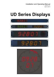
Installation & Operation ManualVersion: 1.CNovember 23, 2004<strong>GM</strong>-<strong>TTT</strong>Master Time Code GeneratorCentral Unit of the MTD Time-Timer-Time Code System
Installation & Operation Manual <strong>GM</strong>-<strong>TTT</strong>Page 23.5 VITC 413.6 STATUS 423.7 TEST 433.8 REFERENCE 443.8.1 MODE 1: Automatic Setting and DST Mode of the Internal Clock 443.8.2 MODE 2: Time for Automatic Setting of the Internal Clock 463.8.3 1 ... 6: Status Data of the Reference Time 473.9 SERIAL 493.9.1 FORMAT: Select the Baud Rate and Format of the Serial Interface 493.9.2 PROTOCOL: Select the Remote Control Protocol 493.10 LTC IN 503.10.1 MODE: Settings for the Operation Mode Using External LTC 503.10.2 OFFSET: Offset Programming for the Time Information 513.10.3 1 ... 3: Status Data of the Readout LTC 513.11 GPI 523.11.1 SET TIME: Pre-set the Comparative Time Value for Relay Switching 523.11.2 SET MODE: Set the GPI Mode 523.12 ZONE 533.12.1 OFFS 1: Time Zone Offset During Normal Time 543.12.2 OFFS 2: Time Zone Offset During Daylight Saving Time (DST) 543.12.3 DST on: Program the Beginning of the Daylight Saving Time 553.12.4 DST off: Program the End of the Daylight Saving Time 553.12.5 DST Period: Indicate Beginning and End of DST of the Current Year 563.12.6 RESET A - F: Reset the Parameters of the Time Zones for Timer A - F 564 GENLOCK 574.1 GENLOCK TO A BLACK-BURST OR VIDEO SIGNAL 574.2 GENLOCK TO A LTC SOURCE 584.3 GENLOCK TO A 1PPS SIGNAL 595 OPERATION WITH A REAL TIME REFERENCE 605.1 CONNECTION OF AN EXTERNAL REFERENCE 605.2 DCF IN OPTION: INSTALLATION OF A DCF77 RECEIVER 615.3 GPS IN OPTION: INSTALLATION OF A GPS RECEIVER 625.4 OPTION T: BATTERY-BUFFERED CLOCK MODULE 645.5 TIME TRANSFER DURING NORMAL OPERATION AND TIME JUMPS 655.6 INTERNAL CLOCK, AUTOMATIC DST MODE, BINARY GROUPS WITH DATEAND STATUS 675.7 REAL TIME COUPLING OF TIME CODE AND VIDEO 686 FURTHER DETAILS 706.1 FACTORY SETTINGS 706.2 MAINTENANCE 727 OPTIONAL MODULES AND FUNCTIONS 737.1 COLOUR LOCK 737.2 VITC GENERATOR 747.3 SERIAL REMOTE CONTROL INTERFACE 757.3.1 General 757.3.2 Commands 76
Installation & Operation Manual <strong>GM</strong>-<strong>TTT</strong>7.4 REFERENCE TIME INPUT VIA EXTERNAL LTC 787.4.1 General 787.4.2 Accepting Time, Date and Status Information of the External LTC 787.4.3 Examples 797.5 SECONDS AND MINUTES PULSE OUTPUT 817.6 ANALOGUE MASTER OUTPUT 82Page 3
Installation & Operation Manual <strong>GM</strong>-<strong>TTT</strong>Page 4A1 Revision HistoryNo. Date Subject0.x September 10, 2002 Preliminary IBC-2002 document, supplementary data may be published soon.1.0 October 31, 20021.1 November 04, 2002 Headlines 3.12.1 and 3.12.2 exchanged.Diagram of chapter “6.2 Maintenance” revised.Some editorial changes.1.2 March 18, 2003 Extension of USER MODE: “A DATE-7”.Chapter 7.4: Reference Time Input via External LTC.1.3 March 28, 2003 Correction at USER MODE: “A DATE-7”: appointment code must be $8 instead of $1.1.4 May 07, 2003 Correction chap. 1.4, pinning GPI: COM1 = pin 6 (not pin 3).1.5 June 10, 2003 Extension of USER MODE: “b OFF”.1.6 June 30, 2003 Option “2“ (RS232) and Option “4“ (RS422): add pinning of DSUB9 at chap. 1.4.Chapter 7.3.1: additional note: because of the missing RS485 interface to the controlunits of the MTD system, <strong>GM</strong>-<strong>TTT</strong> can no longer work as a central unit of this system.1.7 July 08, 2003 Option “P“: addenda at chapters 1.2 and 1.4, new chapter 7.5.1.8 August 22, 2003 Extension of GPI feature, chapter 3.11: timer time to trigger can be C, D, E or F aswell.1.9 November 20, 2003 Range of VITC lines changed, chapter 3.5 and 7.2.Editorial changes at chapter 3.12.3 and 3.12.4.1.A December 08, 2003 Option “A“: addenda at chapters 1.2 and 1.4, new chapter 7.6.1.B February 05, 2004 New submenu “PARA”: main operating mode start programmable.1.C November 23, 2004 Chapter 3.2.5: new formats of setting the date in the binary groups.A2CopyrightCopyright © <strong>Alpermann+Velte</strong> Electronic Engineering GmbH 2002. All rights reserved. Nopart of this publication may be reproduced, translated into another language, stored in aretrieval system, or transmitted, in any form or by any means, electronic, mechanical,photocopying, recording, or otherwise without the prior written consent of <strong>Alpermann+Velte</strong>Electronic Engineering GmbH.Printed in Germany.Technical changes are reserved.All brand and product names mentioned herein are used for identification purposes only, andare trademarks or registered trademarks of their respective holders.Information in this publication replaces all previously published information. <strong>Alpermann+Velte</strong>Electronic Engineering GmbH assumes no responsibility for errors or omissions. Neither is anyliability assumed for damages resulting from the use of the information contained herein.For further information please contact your local dealer or:<strong>Alpermann+Velte</strong>Electronic Engineering GmbHOtto-Hahn-Str. 42D-42369 WuppertalPhone: ++49 - (0)202 – 244 111 0Fax: ++49 - (0)202 – 244 111 5E-Mail: info@alpermann-velte.comInternet: http://www.alpermann-velte.com
Installation & Operation Manual <strong>GM</strong>-<strong>TTT</strong>Page 5A3 Warranty<strong>Alpermann+Velte</strong> warrants that their products will be free from defects in materials andworkmanship for a period of two years from the date of shipment. If this product provesdefective during the warranty period, <strong>Alpermann+Velte</strong>, at its option, will repair or replace thedefective product without charge, provided this product are returned to <strong>Alpermann+Velte</strong>freight prepaid.In order to obtain service under this warranty, Customer must notify <strong>Alpermann+Velte</strong> of thedefect before expiration of the warranty period and make suitable arrangements for theperformance of service. Customer shall be responsible for packaging and shipping thedefective product to <strong>Alpermann+Velte</strong>, please notice the Shipping Information given below.This warranty shall not apply to any defect, failure or damage caused by abuse, misuse,improper use, negligence, accident, modification, alteration, or improper or inadequatemaintenance and care.This warranty is given by <strong>Alpermann+Velte</strong> with respect to this product in lieu of any otherwarranties, express or implied. <strong>Alpermann+Velte</strong> and its vendors disclaim any impliedwarranties of merchantability or fitness for a particular purpose. <strong>Alpermann+Velte</strong>’s responsibilityto repair or replace defective products is the sole and exclusive remedy provided to thecustomer for breach of this warranty. <strong>Alpermann+Velte</strong> and its vendors will not be liable forany indirect, special, incidental, or consequential damages irrespective of whether<strong>Alpermann+Velte</strong> or the vendor has advance notice of the possibility of such damages.
Installation & Operation Manual <strong>GM</strong>-<strong>TTT</strong>Page 6A4 Unpacking/Shipping/Repackaging InformationThis product has been carefully inspected, tested and calibrated before shipment to ensureyears of stable and trouble-free service.The shipping carton and pads provide protection for the product during transit. Retain theshipping cartons in case subsequent shipment becomes necessary.Carefully unpack the product from its transit material and carefully check the product for signsof damage. In the event that the product has been damaged during transit, contact the carrierand your <strong>Alpermann+Velte</strong> dealer.Please confirm that all items listed on the packing list have been received. Check the itemsagainst your original order to ensure that you have received the correct parts. If any item ismissing, please contact your <strong>Alpermann+Velte</strong> dealer.Ensure that all packaging material is removed from the product and its associatedcomponents before installing the unit.Products returned to <strong>Alpermann+Velte</strong> for servicing or repair should have a tag attachedshowing:• Name and complete address of the owner and the name of the person that can becontacted.• Units serial number and a description of the service required or failure detected.Products returned should be shipped prepaid in the original packaging material if possible. Ifthe original packaging is not available or is unfit for use, supply an adequate packagingwhich should meet the following criteria:• Packaging must be able to withstand the product weight.• Product must be held rigid within the packaging.• Allow at least two inches of space between the product and the container.• The corners of the product must be protected.• Seal the carton with shipping tape or an industrial stapler.If the product is still within the warranty period, the product will be returned by prepaidshipment after servicing.
A5 Safety InstructionsInstallation & Operation Manual <strong>GM</strong>-<strong>TTT</strong>Page 7The general safety information in this part is for both operating and service personnel.<strong>Alpermann+Velte</strong> products are only to be used as directed. Specific warnings and cautions willbe found throughout the manual where they apply.Review the following safety instructions to avoid injury and prevent damage to this product orany products connected to it.• Read these instructions.• Keep these instructions.• Heed all warnings.• Follow all instructions.Safety Terms and SymbolsTerms and Symbols in this manual:CAUTION: Caution statements identify conditions or practices that could resultin damage to this product or other property.Terms and Symbols which may be found on the product:ATTENTION: Refer to the manual.Observe precautions for handling electrostatic-sensitive devices.Signal Ground.Product Damage PrecautionsPREVENT OVERHEATINGTo prevent product overheating, position the unit only where sufficient aircirculation can be maintained. Good air circulation is essential to preventinternal heat build-up, do not block any ventilation openings. Do not exposethe unit to direct sun light or any other strong lights. Keep the unit away fromheat sources.PROVIDE PROPER ENVIRONMENTDust, humidity, shocks and strong electromagnetic fields must be avoided. Donot expose this apparatus to dripping or splashing water. Ensure that noobjects filled with liquid are placed on the apparatus.
Installation & Operation Manual <strong>GM</strong>-<strong>TTT</strong>Page 8OBSERVE EMC REGULATIONSThe EMC regulations are observed only under the following condition: usehigh quality shielded cables at data inputs and outputs.SUSPECTED FAILURESWhenever it is likely that safe operation is impaired, the apparatus must bemade inoperative and secured against unintended operation. The appropriateservice authority must then be informed. Do not operate with suspectedfailures. Servicing is required when the apparatus has been damaged in anyway, such as power-supply is damaged, liquid has been spilled or objects havefallen into the apparatus, the apparatus has been exposed to rain or moisture,does not operate normally, or has been dropped.PREVENTIVE MAINTENANCE: CLEANINGQualified Service Personnel Only: The apparatus should be cleaned oftenenough to prevent dust or dirt from accumulating. Dust accumulating in theapparatus acts as an insulating blanket, preventing proper cooling, andpossibly causing overheating and component breakdown. Under high humidityconditions, accumulated dust can also provide an electrical conduction path.Remove accumulated dust with a soft cloth or small paint brush. Removehardened dirt with a soft cloth, dampened in a mild detergent and watersolution. Do not use polish or abrasive cleaners or any other chemical cleaningagents.PREVENTIVE MAINTENANCE: VISUAL INSPECTIONQualified Service Personnel Only: Visually inspect the apparatus for signs ofdamage, scorched components, and loose or disconnected pin connectors. Ifyou discover heat damaged parts, try to determine the cause of theoverheating before replacing the damaged parts; otherwise, the damage mayrepeat.ATTENTION:Observe precautions for handling electrostatic-sensitive devices. See “ElectroStatic Discharge (ESD) Precautions” below for details.
Installation & Operation Manual <strong>GM</strong>-<strong>TTT</strong>Page 9Electro Static Discharge (ESD) PrecautionsAll semiconductor devices are sensitive to ESD. To prevent any damage ordegradation on components of the product caused by ESD, observe theseprecautions when directed to do so (installing, removing sensitivecomponents):1. Use a Ground Strap. Wear a grounded anti-static wrist or heel strap to discharge thestatic voltage from your body.2. Use a Safe Work Area. Avoid handling components in areas that have a floor or worksurface covering capable of generating a static charge. Also nothing capable ofgenerating or holding a static charge should be allowed in the work area.3. Handle ESD sensitive components carefully. Do not slide components over any surface.Do not touch exposed connector pins. Pick-up components by the body, never by theleads.4. Transport and store sensitive components or assemblies in a static-protected bag orcontainer.Battery Use WarningsCAUTION: Danger of explosion if battery is incorrectly placed. Replace onlywith the same or equivalent type recommended by the manufacturer. Discardused batteries according to the manufacturer’s instructions.A6 Certifications & CompliancesCE-Declaration:We,<strong>Alpermann+Velte</strong>Electronic Engineering GmbHOtto-Hahn-Str. 42D-42103 Wuppertalherewith declare under our sole responsibility that the<strong>GM</strong>-<strong>TTT</strong>meets the intent of the following directives, standards and specifications:89/336/EEC Electromagnetic CompatibilityEN 50081-1 Emissions• EN 55022• EN 55103-1EN 50082-1 Immunity• EN 55024• EN 55103-2
Installation & Operation Manual <strong>GM</strong>-<strong>TTT</strong>Page 101 Introduction to the <strong>GM</strong>-<strong>TTT</strong>1.1 OverviewThe <strong>GM</strong>-<strong>TTT</strong>generates linear time code (LTC) and can also optionally generate a verticalinterval time code (VITC). The frames/second can be selected from most widely used formatsincluding 24, 25, 30 and 30 drop frame. The unit generates time code according to theSMPTE standard ANSI/SMPTE 12M-1995 (revision of ANSI/SMPTE 12M-1986) for thetelevision systems 625/50 (PAL) and 525/60 (NTSC).Time and binary groups information are displayed on the 8-digits front display panel. Timeand binary groups can be pre-set by using buttons on the front panel, by an external LTC orby an external reference signal (for e.g. receiving time and date from a DCF77 or GPSreceiver). With the <strong>Alpermann+Velte</strong> MTD system the time may also be set from one of the sixinternal timers A - F (described below).The LTC signal can be phase-locked to it’s own internal reference (x’tal, temperature compensated)or to an external genlocking signal (video or black-burst television signal, external LTCsource, real time seconds pulse).<strong>GM</strong>-<strong>TTT</strong>was designed for video studios and broadcast stations. External synchronising signalspass through special filters, so that noise or other disturbances in these signals do not affectthe time code output. This ensures that the time code is permanently available, continuouslyup-counting, and without any faults even if there is a drop-out of the external synchronisingsignal. Further effort has been made to professionally handle the real time coupling. The unitsupplies all information required to adjust the time code and the SPG (sync pulse generator) toa real time reference signal. Real time references presently include GPS or DCF77 receivers.<strong>GM</strong>-<strong>TTT</strong>is a master time code generator and the central unit of the <strong>Alpermann+Velte</strong> MTDsystem at the same time. <strong>Alpermann+Velte</strong> has uniquely developed a system we call theMultiple Time Display System (MTD). This system supplies the video studio with timeinformation as local time, date, time code, VTR time code, up/down counting timers etc. AMTD system consists of a central generator, digital displays and/or index clocks and at leastone control unit. The central generator generates a specific LTC format which will be referredto as LTC(MTD) in this document. The LTC(MTD) transfers data to all digital displays andincludes all the time information that were mentioned above. The control units communicatewith the central generator via a RS485 bus and are connected to the LTC (MTD)/RS485connector.The front panel of a <strong>GM</strong>-<strong>TTT</strong>has buttons and a display, these are necessary to configure andoperate the unit. All important functions may be switched easily and quickly by using thesebuttons. A KEYLOCK function is available to avoid unintentional key presses (used after anapplication has been properly set-up and changes are no longer needed).
1.2 Optional ModulesThe following options are available:Installation & Operation Manual <strong>GM</strong>-<strong>TTT</strong>Page 11V: VITC generator • VITC contains the same time and binary groups information asthe LTC.C: Colour lock for the625/50 (PAL)television system• 4-field and 8-field, 8-field using the white flag of line 7 of ablack-burst input.L: LTC play speed • LTC Jam-Sync functions,reader, 80-bit and • LTC refresh and regeneration,112-bit code • LTC source synchronisation,• display of the VTR-LTC in the MTD system,• converter of a 112-bit code to a 80-bit code.G: GPI • Relay closure at a programmable time.2: RS2324: RS422• Instead of the RS485 interface used to communicate within theMTD system a RS232 or RS422 serial interface can be used toremote control the unit.P: Pulse outputs • Seconds pulse output and minutes pulse output.A: Analogue MasterOutput• Output to drive analogue clocks with hands.* Special solutions:• Additional independent unbalanced LTC output (at BNC).• Special software according to customer’s need.• Special hardware according to customer’s need.Additionally there are the following configurations to realise a reference time input. Thereference time can set the internal clock at various user definable terms.DCF IN: DCF77 radioclock receiver built-inGPS IN: GPS receiverbuilt-inStandard: Interface toconnect an externalDCF77 or GPSreceiverT: Built-in real timeclock module• Reference time = Central European Time (CET/CEST)transmitted from the German DCF77 transmitter.• Reference time = a time derived from the GPS time, e.g. theUTC.• Input second pulse and serial data of an appropriate externalunit.• Time and date will be set by the buttons of <strong>GM</strong>-<strong>TTT</strong>. Themodule has a real time clock with a battery backup.
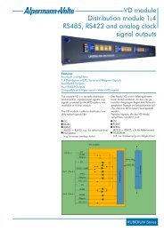
Installation & Operation Manual <strong>GM</strong>-<strong>TTT</strong>Page 121.3 Application DiagramsRedundant Master Time Code System with Reference Time Input and 10MHz GenlockingSPGprimary10MHzGenlockSPGback-up10MHzGenlockBBBBChange-OverUnitInOutInOutBB In / LoopBB In / LoopReferenceData In1ReferenceData In1LTC(MTD)RS485Out1LTC(MTD)RS485Out1<strong>GM</strong>-<strong>TTT</strong>Time CodeGenerator<strong>GM</strong>-<strong>TTT</strong>Time CodeGeneratorP_SECTxDco-ax100mGPSAntennaAnalyser/Switcher1 1 11 1LTC(MTD)10MHzRS485Unit1Out LTC OutData11OutData 2 x Data OutFailureInput 1 Input 22In1LTC(MTD)/RS4853Master Time CodeSystem1Central Unit of the MTD Time-Timer-Time Code Systemco-ax100mGPSAntennaDataOut1P_SECTxDBlackBurstBB In / Loop1ReferenceData InLTC(MTD)Out1 23LTC(MTD)RS485Out1<strong>GM</strong>-<strong>TTT</strong>Time CodeGeneratorAC/DCV+/V-12:59:59 A11KDBLTC(MTD)/RS485KDAMTD BESlave ClocksACMaster1KSOKOL12:59:592 1MTD Displays3KXA1 23KXAMTD BTKSC11 112:59:59MTD BDKDA12:59592 1312:59:59KXA1 22 1331 22 13KXA12:59:59312:59:59 AMTD BE1911System2
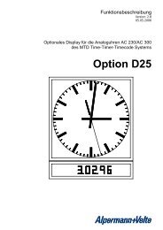
Installation & Operation Manual <strong>GM</strong>-<strong>TTT</strong>1.4 Connections at the Rear and Technical DataPage 13DSUB9FXLR4M XLR3M XLR3FDSUB9FDSUB9M2 x BNC2 x BNC111off 1MTD1 42 3DC IN1 23LTC OUT2 13LTC IN1GPIREF.DATA IN2OPTIONoff75Ω2VIDEO/BBDimensions: 214.5 (W) x 43.5 (H) x 140 (D) mm (½ 19“, 1U)Weight:1.5 kg approx.Operating temperature: 5 °C to 40 °CRelative humidity: 35% to 85%, non-condensingMTDLTC(MTD)/RS485 connectorSpecifications for LTC_x/LTC_y see LTC OUTInstead of LTC(MTD)/RS485signals: pinning in case ofoption “2“ (RS232) oroption “4“ (RS422)Option “2“ (RS232):2: RxD (in) 5: GND3: TxD (out) 7: RTS (out)4: DTR (out) 8: CTS (in)1, 6, 9: not connectedPin 1: RS485 TRA (input/output)Pin 2: RS485 TRB (input/output)Pin 3: LTC_x (output)Pin 4: LTC_y (output)Pin 5: GNDPin 6-8: reservedPin 9: DRVSELOption “4“ (RS422):1, 5: n.c. 6: TxC2: TxB (out) 7: TxA (out)3: RxA (in) 8: RxB (in)4: RxC 9: frameDC INPower Consumption:without additional options = 3 W; maximal = 8 W.Pin 1: V- (GND)Pins 2/3: not connectedPin 4: V+: 10 - 30 V DC (except withoption “A”: 10 - 18 V DC)LTC OUTLTC_x/LTC_y: LTC signal, balanced.• Level: 35 mV pp - 3 V pp adjustable.• Impedance: 12 kΩ.• LTC input frequency: 1500 - 3000 bps=19 - 37 frames/s 80-bit code,= 14 - 26 frames/s 112-bit code.Pin 1: GNDPin 2: LTC_x (input)Pin 3: LTC_y (input)LTC input accepted for genlocking:frame rate = 24: 24 frames/s ±1.4%,frame rate = 25: 25 frames/s ±1.5%,frame rate = 30: 30 frames/s ±1.8%.
Installation & Operation Manual <strong>GM</strong>-<strong>TTT</strong>Page 14GPIOption G: Relay pointsSwitcher COM1-NC1 (Normally Closed)and COM1-NO1 (Normally Open).• Max. switchable power: 5 W.• Max. switchable voltage: 175 V.• Max. switching current: 0.25 A• Max. transportable current: 1 AOption P: Pulse outputsTTL level pulsesOption A: Power supply and data telegram to driveanalogue clocks.Pin 1: NC1Pin 2: NO1Pin 6: COM1Pin 3: Seconds pulsePin 4: Minutes pulsePin 5: GNDPin 1: V+ OutPin 2: V- OutPin 7: Signal OutPin 8: Signal GNDREF. DATA INInterface for the external reference time input, it ismissing in case of a built-in reference.P_SEC: 1pps signal (seconds pulse), internal triggerat rising or falling edge according toselection (menu REFER - MODE 1).Input low: max. 0.8 V.Input high: 2-15 V.RxD: Serial data protocol with fixed format(Meinberg): 2400/7/E/2.Input low: max. 0.8 V.Input high: 2-15 V.With option GPS IN:DSUB9M “DC GPS IN“Pin 1: P_SECPin 2: RxDPin 5: GNDPin 6: V+ = 11 - 30 VDC, 2WPin 7: V- (GND)OPTION 1With option DCF IN:BNC antenna input.With option GPS IN:SMA antenna input.BNC, 50 ΩSMAOPTION 2With option V (VITC generator): video + VITCoutput, according to SMPTE 12M-1995.Video output: gain = 1 ±1%.BNC (IEC 169-8), 75 Ω
Installation & Operation Manual <strong>GM</strong>-<strong>TTT</strong>Page 15VIDEO/BBInput + loop-through of a CVBS or black-burstsignal. Set 75 Ω termination switch to “on” positionif the loop-through should be left open.With option V (VITC generator) the video input levelshould have 1V pp ±15 mV.Using this input only for video genlock the syncamplitude should have 300 mV ± 6 dB.2 x BNC (IEC 169-8), 75 Ω
Installation & Operation Manual <strong>GM</strong>-<strong>TTT</strong>Page 161.5 Functions of Buttons, OverviewBUTTON FUNCTIONmenu↑ ↓ →enterSwitching on/off the menu lines.Buttons to operate in the menu, see detailed menu description.Button to operate in the menu, see detailed menu description.Pressed if menu is switched off: status display, the display shows type of theunit, configuration and software revision in same steps as after power-on.time/user Switches the display to show the time or binary groups information of thetime code. Terminates any menu operation.key lockSwitching on (LED lights up) or off (LED off) the Key Lock feature.Key Lock “on” means: the buttons enter, intern, genlock, time, timer, tc andstart are without function. So an unintentional key stroke do not lead to anunwanted function, only the display can be switched. Setting time or dateusing an operational unit of the MTD system is disabled.internSwitches on the genlock to internal reference signal (temperaturecompensated x’tal).genlock Switches on the genlock to the input source as selected at the menu SET -LOCK. Input genlock can be one of three sources: video or black-burst, LTCinput signal, seconds pulse of a real time reference.timetimertcstartSelect LTC generator operating mode: reference time input. The LTC timeinformation corresponds to the reference time input (± offset as selected atthe menu ZONE - OFFS1 and OFFS2).With every key stroke the generator synchronises again to the referencetime, so the generator is forced manually to a synchronisation additional tothe automatic synchronisation as selected at the menu REFER - MODE1 andMODE2.Select LTC generator operating mode: time of a MTD timer. The LTC timeinformation corresponds to one of the MTD timer A - F, as selected at themenu TIMER - TIME A-F.Select LTC generator operating mode: LTC Jam-Sync feature. Transfersdata from LTC input to LTC output, as selected at the menu LTC IN -MODE.Select LTC generator operating mode: free-running mode.If enabled at submenu SET - ... - PARA: with every further key stroke thetime value which has last been chosen as a start value (menu SET - START)will be transferred to the LTC time information, and the generator keeps oncounting continuously from this start value on.
Installation & Operation Manual <strong>GM</strong>-<strong>TTT</strong>1.6 Status Indication by LED’s, OverviewPage 17LEDFUNCTIONtime/user On: the display shows the time information of the time code (providedthe menu has been switched off).Off: the display shows the binary groups information of the time code(provided the menu has been switched off).key lock On: Key Lock enabled.Off: Key Lock disabled.intern On: genlock to internal reference selected.LED lights up as well if genlock = seconds pulse is selected and thegenerator currently stays in a coarse trim.genlockCase genlock = video or black-burst selected at menu SET - .. - LOCK:Lights up if genlock is operating normally. Flashes if the genlock signalis disturbed and the internal reference is currently selected. If thegenlock signal returns to be ok the LED will light up again.Case genlock = LTC input signal is selected at menu SET - .. - LOCK:Lights up if genlock is operating normally. Flashes if the genlock signalis disturbed or the frequency of the LTC input signal is beyond thespecified range, then the internal reference is currently selected. If thegenlock signal returns to be ok the LED will light up again.Case genlock =seconds pulse is selected at menu SET - .. - LOCK:Lights up if genlock is operating normally. This only can be achieved ifthe seconds pulse is stable, i.e. the jitter must not exceed 1.2ms.Flashes if the genlock signal is disturbed or the generator currentlystays in a coarse or fine trim. The coarse trim will be indicated by LEDintern as well. Coarse trim means: frame 0 of the time code is morethan 16ms apart from the seconds pulse. Fine trim means: frame 0 ofthe time code is between 1.2ms and 16ms apart from the secondspulse.timetimertcstartIndicates the LTC generator operating mode: reference time input.Indicates the LTC generator operating mode: time of a MTD timer.Indicates the LTC generator operating mode: LTC Jam-Sync feature. LEDlights up if LTC input is accepted, else LED flashes.Indicates the LTC generator operating mode: free-running mode.
Installation & Operation Manual <strong>GM</strong>-<strong>TTT</strong>Page 18freemod.Indicates the status of the reference time input:On: the serial data input indicates a free running mode, for example aGPS or DCF77 receiver has not locked to the antenna signal.Off: the reference time source has locked to the antenna signal.Only with option GPS IN: a flashing LED indicates the number of satellitesfound by the receiver.LED flashes every time that serial data of a reference time input has beenreceived. In normal operation that will be a flash every second.Only with option DCF IN: LED indicates the time telegram, this should bea flash every second as well - with no flicker in between. At the 59 thsecond the flash will be suppressed.cf Off: no colour lock mode selected.On: colour lock mode is selected and the corresponding flagbit of the time code is set, if V8 (8-field) lock is reached inthe 625/50 system.Flashing slowly: colour lock mode is selected and V4 (4-field) lock isreached in the 625/50 system.Flashing fast: colour lock mode is selected but no colour lock can bereached.25 On: frame rate = 25 (television system 625/50).LED off + LED 30 off: frame rate = 24.30 On: frame rate = 30 Drop Mode (television system 525/60).Flashing: frame rate = 30.LED off + LED 30 off: frame rate = 24.
Installation & Operation Manual <strong>GM</strong>-<strong>TTT</strong>1.7 The Menu Structure, OverviewPage 19SETTIMERSET STARTSET USERSET TIMESET DATEUSER MOD.LOCKF-RATEPARAFACTORYTIME A-FU STOREU LOADU RESETA (data)B (data)C (data)D (data)E (data)F (data)Enter a start value of the time code generator.Enter user defined data for the binary groups of the time code.Set the time of the internal clock.Set the date of the internal clock.Select what kind of information should appear in the binarygroups.Select the genlock and the colour lock mode.Select frame rate and television system.More system parameters.Factory reset, all current parameters except ‘user area’ and ‘timezone parameters’ can be reset to default values.Select a MTD timer (A ... F or Main Timer 1) and timer mode forthe timer operating mode.All current settings including the parameters set from a MTDoperational unit can be stored to an ‘user area’.The parameters stored in an ‘user area’ can be loaded, the unitwill be forced to start anew.The parameters stored in an ‘user area’ can be reset to defaultvalues.Display timer A (test purpose only).Display timer B (test purpose only).Display timer C (test purpose only).Display timer D (test purpose only).Display timer E (test purpose only).Display timer F (test purpose only).LTCVITCSTATUSOUTSelect the LTC output level.POLARITY Select the use of the polarity bit.1 (data) Display the six time code flag bits of the LTC generator.Enter the VITC set mode.1 (data) Display internal register for test purposes.2 (data) Display CPU efficiency and ports.3 (data) Display current programming of the internal reference signal.4 (data) Display error counter: all faulty events of the genlock signal.5 (data) Display error counter: failures of the genlock signal.
Installation & Operation Manual <strong>GM</strong>-<strong>TTT</strong>Page 206 (data) Display error counter: disturbances at the genlock signal.7 (data) Display internal register for test purposes.8 (data) Display internal register for test purposes.TEST(data)(data)(data)Display delay between internal and external genlock signal.Display period of the external genlock signal.Display delay between second pulse and video or black-burstgenlock signal.REFERMODE 1 Automatic setting and DST mode of the internal clock.MODE 2 Time for automatic setting of the internal clock.1 (data) Indication of the time of the reference time.2 (data) Indication of the date of the reference time.3 (data) The last time, when the data of the reference time showed the"lock" status.4 (data) The last date, when the data of the reference time showed the“lock“ status.5 (data) Offset between the reference time and the internal clock.6 (data) Status information resulting from the data of the reference time.SERIALFORMATPROTOCOLSelect the baud rate and format of the serial interface (option).Select the remote control protocol (option).-- Reserved.LTC INMODE Settings for the operation mode using external LTC.OFFSET Offset programming for the time information.1 (data) Indication of the readout LTC time.2 (data) Indication of the binary groups of the readout LTC3 (data) Indication of the current six flag bits of the readout LTCGPISET TIMESET MODEPre-set the comparative time value for GPI relay switching.Set the GPI mode.ZONEOFFS 1 Time zone offset during normal time.OFFS 2 Time zone offset during Daylight Saving Time (DST).DST on Program the beginning of the DST.DST off Program the end of the DST.(DST period) Indicate beginning and end of DST of the current year.RESET A-F Reset the parameters of the time zones for the timer A - F.
1.8 After Power-OnInstallation & Operation Manual <strong>GM</strong>-<strong>TTT</strong>Page 21After switching on the unit the data of the non-volatile memory will be tested. If the test failsthe display shows “RESET” and the factory values will be stored. If the test passes the unit willbe set into same state as before switching off.After this test the display shows status messages in three steps. At same time all LED’silluminate for test purposes. Steps 1 and 2 show the hardware and software configuration,step 3 the result of the check of the time zone parameters of the MTD timers A - F.Step 1, display shows e.g.:Digit 8 Digit 7 Digit 6 Digit 5 Digit 4 Digit 3 Digit 2 Digit 1Digits 8 and 7 indicates the type of the unit: “<strong>GM</strong>”.Digit 5 shows if there are any modules plugged. Digit 5 shows a hexadecimalnumber, with following meanings of the single bits:Bit 0: =1, if VITC generator is plugged.Bit 1: =1, if any serial interface (RS485, RS232, RS422) is plugged.Bit 2: =1, if colour lock module is plugged.Digit 4 shows the current selection of the USER MODE.Digits 3 and 2 shows the software revision (e.g. 1.0).Digit 1 = blank in a standard configuration. Any special configuration will beindicated by an ‘o’ at this place.Step 2, display shows e.g.:Digit 8 Digit 7 Digit 6 Digit 5 Digit 4 Digit 3 Digit 2 Digit 1Digit 8: =1, if the remote control via serial interface is basically enabled.Digit 7: reserved.Digit 6: =1, if the Real Time Reference operation is basically enabled.Digits 5..3 = blank if digit 6 = 0, else:Digit 5: indicates the kind of serial interface used to receive real time data(DCFSIO).Digit 4 =0: no use of a real time seconds pulse.=1: seconds pulse is used, rising edge.=2: seconds pulse is used, falling edge.Digit 3: indicates the protocol used to receive real time data.Digits 2 and 1 identifies any special configuration by two numbers.
Installation & Operation Manual <strong>GM</strong>-<strong>TTT</strong>Page 22Step 3, display shows e.g.:Digit 8 Digit 7 Digit 6 Digit 5 Digit 4 Digit 3 Digit 2 Digit 1F E D C B AThe time zone parameters of the MTD timer A ... F has been checked. The display shows theresult: an “o” means ok, “n” means parameter check failed, this time zone has been reset tostandard values. Digit 1 refers to time A etc.The internal clock is set to time = 00:00:00 and date = 01.01.2002. Now the unit tries tolock to the selected genlock mode. At the same time measurements are made to analyse thetiming between the incoming reference data (P_SEC, serial data) and the LTC output frames.The LTC output still will be “quiet”, the goal is to start the LTC with a locked frequency andwith valid data (internal clock locked to a reference time). With the operating mode = time itwill take about 18 seconds to have everything locked and to enable the LTC output.
2 Main Operating Modes2.1 Fundamental PrinciplesInstallation & Operation Manual <strong>GM</strong>-<strong>TTT</strong>Page 23<strong>GM</strong>-<strong>TTT</strong> can be used in different applications, as there are:• generating a stable master LTC and VITC,• real time, local time, time zone applications,• converter LTC-to-LTC and/or LTC-to-VITC,• central unit of a timer system,• and more.<strong>GM</strong>-<strong>TTT</strong> is able to handle some of these applications simultaneously. To use the unit mosteffective and perfect, it is important to understand, how the unit works. The operator should beaware of the following four subjects:LTC output frequencyThe LTC output is a kind of an audio signal with a specific frequency. This signal should be asaccurate and stable as possible. It can be locked to an external signal. This feature will beadjusted by frame rate selection and intern/genlock selection.Internal clockThe unit has an internal clock counting time and date. This clock can be set by a built-in or externalreference time. The time (and date) can be transferred to the bits of the (standard) LTC,time and date are also accessible as data of the LTC(MTD). Time zone and Daylight SavingTimes (DST) features can give the internal clock a different time compared to the reference,this programming is done in the REFER. and ZONE menu. The accuracy of this clock dependson the LTC output frequency, because the frequency of the LTC is the frequency of the clock!Time code information: time addressFour basic operating modes are provided, accessible by the buttons time, timer, tc and start.These operating modes define the data content of the time addresses:• time: Time of the internal clock.• timer: Time of any timer of the MTD system, as selected at menu TIMER - TIME A-F.• tc: Jam-Sync mode: time of the LTC input or free-running counter, as selected atmenu LTC IN - MODE• start: Free-running counter.Time code information: binary groupsThe binary groups are intended for storage and transmission of user defined data. In principlethe unit uses the unspecified character set, i.e. the binary group flags BGF0, BGF1, BGF2 areset to zero. Selection at menu SET - ... - USER MOD defines the data content of the binarygroups for three different kinds of data:• fixed values, free selectable by the user;• multiplexed data of the LTC(MTD);• the date of the internal clock, at various formats.Additionally the binary groups can get their data from the Jam-Sync feature.There is a mixing up of all these subjects, so some combinations may work, some not. Thefollowing chapters will give some more detailed examples of how to set-up the unit.
Installation & Operation Manual <strong>GM</strong>-<strong>TTT</strong>Page 242.2 Time Operating ModeSelect this operating mode for a real time or local time application. Please notice chapter“Operating with a Real Time Reference” for installation hints.LTC output frequency• 1 st preference: If the unit works within a television system, choose genlock to a black-burstor video signal (select genlock = bb at menu SET - ... - LOCK and press genlock button).For a perfect solution the SPG should be locked to a stable real time reference - seechapter “Video and Time Code Locked to a Real Time Reference”.• 2 nd preference: With a stable real time reference (stable 1pps signal) choose genlock to a1pps signal (select genlock = SEC at menu SET - ... - LOCK and press genlock button).• 3 rd preference: With a stable external LTC signal (not a VTR LTC) choose genlock to LTCinput (select genlock = LTC at menu SET - ... - LOCK and press genlock button).• 4 th preference: Press intern button to select the internal reference.Internal clock, time/date handling and time address of the time code• The data content of the time addresses is exactly the time of the internal clock.• The internal clock get a pre-set from a built-in or external real time reference. The mode ofoperating with the reference time input is selected at menu REFER - MODE1 and MODE2.Time zone programming is done at submenu ZONE (select the offset and the DaylightSaving Times).Time code information: binary groups• As selected at menu SET - ... - USER MOD.
2.3 Timer Operating ModeInstallation & Operation Manual <strong>GM</strong>-<strong>TTT</strong>Page 25This operating mode enables to manipulate the time addresses of the LTC output by using anoperational unit of the MTD system.LTC output frequency• 1 st preference: If the unit works within a television system, choose genlock to a black-burstor video signal (select genlock = bb at menu SET - ... - LOCK and press genlock button).• 2 nd preference: Press intern button to select the internal reference.Internal clock and time/date handling• The internal clock get a pre-set from a built-in or external real time reference. The mode ofoperating with the reference time input is selected at menu REFER - MODE1 and MODE2.Time zone programming is done at submenu ZONE (select the offset and the DaylightSaving Times). Time and date are part of the multiplexed data of the binary groups (theLTC(MTD) format), thus the displays of the MTD system can decode and display time anddate.Time code information: time address• The time addresses follow the time of a timer of the MTD system, as selected at menuTIMER - TIME A-F. There are two modes selectable: 6-digits and 8-digts mode. Please seeat “Detailed menu description” for more information.Time code information: binary groups• Operation in the MTD system requires to have SET - ... - USER MOD. = 1 <strong>TTT</strong> selected,thus the binary groups contain multiplexed data (the LTC(MTD) format).
Installation & Operation Manual <strong>GM</strong>-<strong>TTT</strong>Page 262.4 TC Operating ModeSelect this operating mode for a Jam-Sync application like refreshing, regenerating, synchronisationetc.The LTC generator accepts data from the LTC input after the LTC has passed three tests:‘forward’ direction must be detected, it must contain a valid time and the time addresses oftwo consecutive frames must be in ascending and continuous order.Submenu LTC IN provides all adjustments regarding the Jam-Sync operating mode. The Jam-Sync can operate as a One Time Jam-Sync, as a Continuous Jam-Sync, or as Jam-Sync withStop:• One Time Jam-Sync: having accepted the first data of the LTC input the One Time Jam-Sync will transfer these data to the generator, then the tc operating mode will be switchedoff and the start operating mode will be switched on automatically. If binary groups datashould be transferred and kept, then USER MODE = 0 SET should be selected (at menuSET - ... - USER MOD)!• Continuous Jam-Sync: with this mode the generator keeps on counting if there are no LTCinput (unlimited flying wheel).• Jam-Sync with Stop: this mode forces the generator to stop after a programmed number offrames if there are no LTC input (drop-out compensation) and if the Jam-Sync is programmedto transfer time data. In case of such a stop the LTC output can completely be suppressed(Stand-By feature) or LTC can be generated having equal time addresses in eachframe (Still feature).LTC output frequency• 1 st preference: If the unit works within a television system, choose genlock to a black-burstor video signal (select genlock = bb at menu SET - ... - LOCK and press genlock button).• 2 nd preference: With a stable external LTC signal choose genlock to LTC (select genlock =LTC at menu SET - ... - LOCK and press genlock button). The LTC output gets a frequencyand phase adjustment to the LTC input. With this genlock mode it can be programmed(menu LTC IN - MODE) that a data transfer from LTC input to LTC output only happens ifthe generator locks to the LTC input, so no Jam-Sync at jog or shuttle frequencies will beallowed.• 3 rd preference: Press intern button to select the internal reference.Internal clock, time/date handling• The internal clock get a pre-set from a built-in or external real time reference. The mode ofoperating with the reference time input is selected at menu REFER - MODE1 and MODE2.Time zone programming is done at submenu ZONE (select the offset and the DaylightSaving Times).• If any time and/or date applications should be kept during the tc operating mode, the LTCoutput frequency should be locked to a stable reference, because this is the frequency ofthe internal clock as well. The internal clock can be programmed to get a time and dateupdate every second (menu REFER - MODE 1), in that case the internal clock follows thereference time mostly independent from the LTC output frequency. The transfer of binarygroups data from the LTC input should be switched off (menu LTC IN - MODE), so thebinary groups of the LTC output contain the data as selected at menu SET - ... - USER
Installation & Operation Manual <strong>GM</strong>-<strong>TTT</strong>Page 27MOD, for example the date (different formats) or the time and date of the LTC(MTD)format for use in the MTD system.Time code information: time address• The time addresses depends on the mode selected at menu LTC IN - MODE: if no transferof time data is selected (only binary groups data transfer), the time addresses will becounted as a free-running counter, just counting on from the values present beforeswitching on the tc operating mode.• If at menu LTC IN - MODE a transfer of time data is selected, the following features areavailable:• Without the offset feature: Using a frame compensation mechanism the timeaddresses of the LTC output correspond exactly to the time addresses of the LTCinput. A break in the LTC input time will appear at the LTC output with threeframes delay.• Offset feature: select a hours:minutes:seconds:frames offset to compensate orcreate a delay between LTC input and LTC output time addresses. This feature canbe switched on or off.Time code information: binary groups• The binary groups of the LTC output depends on the mode selected at menu LTC IN -MODE: if no transfer of binary groups data is selected (only time data transfer), the binarygroups contain data as selected at menu SET - ... - USER MOD.• If at menu LTC IN - MODE a transfer of binary groups data is selected, the followingfeatures are available:• Direct binary groups data transfer, with a delay of one frame.• Cross Jam-Sync: transfer the time addresses of the LTC input to the binary groupsof the LTC output. The features Offset and Stop (with drop-out compensation) thenoperates on the binary groups of the LTC output. The time addresses of the LTCinput will exactly appear in the binary groups of the LTC output (using a framecompensation mechanism).
Installation & Operation Manual <strong>GM</strong>-<strong>TTT</strong>Page 282.5 Start Operating ModeFree-running counter operating mode: when this mode is initiated by the start button, the unitsimply switches to a free-running counter mode internally.Pressing this button during start operating mode and having the START function enabled (atsubmenu SET - ... - PARA): the time value which has last been chosen as a start value (menuSET - START) will be transferred to the time addresses of the LTC output, and the generatorkeeps on counting continuously from this start value on.LTC output frequency• 1 st preference: If the unit works within a television system, choose genlock to a black-burstor video signal (select genlock = bb at menu SET - ... - LOCK and press genlock button).• 2 nd preference: With a stable external LTC signal (not a VTR LTC) choose genlock to LTC(select genlock = LTC at menu SET - ... - LOCK and press genlock button).• 3 rd preference: Press intern button to select the internal reference.Internal clock, time/date handling• The internal clock get a pre-set from a built-in or external real time reference. The mode ofoperating with the reference time input is selected at menu REFER - MODE1 and MODE2.Time zone programming is done at submenu ZONE (select the offset and the DaylightSaving Times).• If any time and/or date applications should be kept during the start operating mode, theLTC output frequency should be locked to a stable reference, because this is the frequencyof the internal clock as well. The internal clock can be programmed to get a time and dateupdate every second (menu REFER - MODE 1), in that case the internal clock follows thereference time mostly independent from the LTC output frequency. The binary groups ofthe LTC output may contain time and/or date, as selected at menu SET - ... - USER MOD,for example the date (different formats) or the time and date of the LTC(MTD) format foruse in the MTD system.Time code information: time address• Free-running counter, starts with the values selected at menu SET - START (if enable atmenu SET - ... - PARA).Time code information: binary groups• As selected at menu SET - ... - USER MOD.
Installation & Operation Manual <strong>GM</strong>-<strong>TTT</strong>3 Detailed Menu Description3.1 General DescriptionPage 29The menu lets you adjust parameters or pre-set values, or it shows test and status data. Themenu button switches on or off the menu. With ↑ and ↓ buttons you will go to the varioussubmenus, with the → button you reach all the items present at this submenu. Chapter 1.7gives an overview of the menu structure. The enter button executes functions, starts set modesor stores settings.Pressing the menu button to switch the menu off the display will return to show the time orbinary groups data. Pressing this button during a set mode will quit this mode and no newsetting will be stored. Same applies if the time/user button is pressed.If there has been a change to any setting <strong>GM</strong>-<strong>TTT</strong> stores the new data into the non-volatilememory. The display shows “store” and no key stroke will be acknowledged during that time.3.2 SETSETSET STARTSET USERSET TIMESET DATEUSER MOD.LOCKF-RATEPARAFACTORYEnter a start value of the time code generator.Enter user defined data for the binary groups of the timecode.Set the time of the internal clock.Set the date of the internal clock.Select what kind of information should appear in the binarygroups.Select the genlock and the colour lock mode.Select frame rate and television system.More system parameters.Factory reset, all current parameters except ‘user area’ and‘time zone parameters’ can be reset to default values.3.2.1 SET START: Enter a Start ValuePress the enter button to enable the pre-set of a start value (referred to the time address of thetime code). The last pre-set value appears at the display. The values of the flashing pair ofdigits can be changed using the ↑ or ↓ button, the next pair can be selected using the →button. The allowed range will be 00-23 of the hours, 00-59 of the minutes and seconds, 00-23/24/29 of the frames - dependent on the frame rate. Press the enter button to store thevalues and to quit the menu.Whenever the start button is pressed in the start operating mode and the START function isenabled (submenu SET - ... - PARA), the generator starts its free-running counter with this startvalue.
Installation & Operation Manual <strong>GM</strong>-<strong>TTT</strong>Page 303.2.2 SET USER: Enter User Defined Data for the Binary GroupsPress the enter button to enable the pre-set of user defined data for the binary groups of thetime code. The last pre-set value appears at the display. The value of the flashing digit can bechanged using the ↑ or ↓ button, the next digit can be selected using the → button. Theallowed range will be 0-9 and A-F, i.e. a hexadecimal value. Press the enter button to storethe values and to quit the menu.Digit 8 Digit 7 Digit 6 Digit 5 Digit 4 Digit 3 Digit 2 Digit 1BG8 BG7 BG6 BG5 BG4 BG3 BG2 BG1It depends on the setting of the USER MODE (at menu SET - ... - USER MOD) and - if the tcoperating mode selected - on the setting at menu LTC IN - MODE, whether the user defineddata appear at the LTC output:tc operating mode is not selected:• USER MODE = 0 SET: the binary groups of the time code get all the user defined data.• USER MODE = 2 DATE: binary groups 1 to 6 are reserved for day, month and year of theinternal clock. Only binary groups 7 and 8 correspond to the two most significant digits ofthe pre-set values.• With all other settings of USER MODE the binary groups are reserved for other functions.tc operating mode is selected:• If at LTC IN - MODE any mode is selected, which transfers data into the binary groups ofthe time code generator, then this feature overwrites any other user defined data of thetime code output.• If only a data transfer to the time addresses has been selected, then the same applies asdescribed at “tc operating mode is not selected” above.3.2.3 SET TIME: Set the Time of the Internal ClockPress the enter button to enable the pre-set of the time of the internal clock. The value of theflashing pair of digits can be changed using the ↑ or ↓ button, the next pair can be selectedusing the → button. The allowed range will be 00-23 of the hours, 00-59 of the minutes andseconds. Press the enter button to transfer the values to the internal clock and to quit themenu.• With option T or GPS IN the time of the built-in reference is set at the same time.• Usually the time of the internal clock will be set automatically by an external reference.3.2.4 SET DATE: Set the Date of the Internal ClockPress the enter button to enable the pre-set of the date of the internal clock. The current valueappears at the display, in the format day/month/year at the place of minutes/seconds/frames.The value of the flashing pair of digits can be changed using the ↑ or ↓ button, the next paircan be selected using the → button. Pressing the enter button the unit checks the input for avalid date, then the values will be transferred to the internal clock.• With option T or GPS IN the date of the built-in reference is set at the same time.• Usually the date of the internal clock will be set automatically by an external reference.
Installation & Operation Manual <strong>GM</strong>-<strong>TTT</strong>3.2.5 USER MOD.: Data Content of the Binary GroupsPage 31Press the enter button to define the data content of the binary groups. The current selectionappears at the display. Use the ↑ or ↓ button to step through the different items. Press theenter button to confirm your choice and to quit the menu.Please notice: in the tc operating mode the data content of the binary groups will beoverwritten, if the Jam-Sync mode includes a transfer of the binary groups.Digit 8 Digit 7 Digit 6 Digit 5 Digit 4 Digit 3 Digit 2 Digit 10 SET The binary groups get user defined data, see 3.2.2 SET USER.1 <strong>TTT</strong> The binary groups get multiplexed data for use in the MTD Time-Timer-Time CodeSystem. The specific LTC(MTD) will be generated.2 DATE The binary groups 1 to 6 get the date of the internal clock, BCD format: day =groups 5+6 (“minutes“), month = groups 3+4 (“seconds“), year = groups 1+2(“frames“). The year is coded with two digits. The groups 7+8 (“hours”) get theuser defined data, see 3.2.2 SET USER. Look at the table of the end of this chapterfor a survey of the date formats.3 STATUS The binary groups 1 to 6 get the date of the internal clock, same as at 2 DATE.The groups 7+8 (“hours”) contain status information:Bit(s) Group 7 (“units of hours“):0 = 1 if the time addresses of the time code output are synchronised to areference time, which is locked. This bit is set in operating mode timeonly. Within the last 24 hours the internal clock must have received a presetfrom a reference time, which is locked itself. The lock status of thereference time is indicated by status information of the serial data inputand is visibly indicated by the LED free.1+2 = time zone of the internal clock: bit 2 bit 10 0 = UTC0 1 = CET1 0 = CEST.3 = 1 during announcement start/end of Daylight Savings Time, one hourbefore the changing occurs.Bit(s) Group 8 (“tens of hours“):0 = 1 during announcement of a leap second, one hour before thechanging occurs.1 Y2K flag: =1, if the two digits coded year is less 98, else it is = 0. See “5DATE-2” as well.2 not used, = 0.3 not used, = 0.Look at the table of the end of this chapter for a survey of the date formats.
Installation & Operation Manual <strong>GM</strong>-<strong>TTT</strong>Page 324 BBC All binary groups are used for the date, with a special format accordingto EBU Technical Information I29-1995 (BBC format). The date is BCD-coded andassigned to the binary groups as follows:BG1 reserved bits = 0BG2 units of the day 4 bits, lsb = bit 12BG3 units of the month 4 bits, lsb = bit 20BG4 tens of the day 2 bits, lsb = bit 28tens of the month 1 bit = bit 30, bit 31 = 0BG5 reserved bits = 0BG6 units of the year 4 bits, lsb = bit 44BG7 reserved bits = 0BG8 tens of the year 4 bits, lsb = bit 605 DATE-2 All binary groups are used for the date of the internal clock, BCD format: day =groups 7+8 (“hours“), month = groups 5+6 (“minutes“), year = groups 1 to 4(“seconds” and “frames“). The year is coded in four digits, valid from 1998 to2097. The reference input of the date may have the year only with two digits, sothe following rule applies: with the two digits coded year < 98 the century will be20, else 19. After power-on the unit starts with the date 1.1.2002. Look at thetable of the end of this chapter for a survey of the date formats.6 DATE-37 DATE-48 DATE-59 DATE-6There are more formats of the date selectable, similar to the selection “2 DATE“.Please look at the table of the end of this chapter for a survey of the date formats.A DATE-7 Conforming to a “TVE” specification:• The arrangement of Day, Month and Year conforms to “8 DATE-5”.• BG1 gets an appointment code = $8, BG8 gets a check sum = bit-wisecomplement of the sum (modulo-16) of BG1 to BG7.• Additionally the binary group flag BGF2 is set to 1.b OFF nnCoding of date and a time offset, conforming to LEITCH CSD-5300 format withAuxiliary Offset. The binary groups are used for the date as described under “4BBC”. Additionally an offset is encoded in 30-minute increments. 6 bits in binaryform are split into two 3-bit groups and are inserted into the reserved binarygroups BG5 and BG7:BG5 offset, 3 lower bits 3 bits, lsb = bit 36BG7 offset, 3 upper bits 3 bits, lsb = bit 52This allows an offset in the positive direction of up to 23 hours 30 minutes, or 47half hour steps (101111 in 6-bits binary form). Devices decoding these bits addthis offset to the time information of the time code. The date coded in the binarygroups is not coupled with that offset, i.e. the date changes at 24 o’clock of thetime information of the time code.
Installation & Operation Manual <strong>GM</strong>-<strong>TTT</strong>Having “b OFF“ at menu USER MOD. selected, use → button to change theoffset. Use enter button to store a new offset.Offset nnInDescriptionAutomatic setting of the offset such that the result of adding theoffset to the time information gives the reference time, i.e.OFFS1 or OFFS2 respectively (dependent on the current timezone) of menu ZONE will be inverted and encoded:Reference time = UTC, <strong>GM</strong>-<strong>TTT</strong> generates a local time withDST (‘Mode’ parameter at menu REFER - MODE1 = u). Usingthe offset it is possible to compute the UTC again.Reference time = a local time with DST, <strong>GM</strong>-<strong>TTT</strong> generatesUTC (‘Mode‘ parameter at menu REFER - MODE1 = i). Usingthe offset it is possible to compute the local time again.Example: reference time = UTC, <strong>GM</strong>-<strong>TTT</strong> generates CET/CESTwith an offset of one hour at normal time (OFFS1 = 01) andan offset of two hours at DST (OFFS2 = 02). During normaltime the offset encoded at BG5 and BG7 is equal to minus onehour (= +23 hours = 46 10 = 101110 2 ), during DST the offsetencoded at BG5 and BG7 is equal to minus two hours (= +22hours = 44 10 = 101100 2 ).00 - 47 Fixed offset for all times, independent from a time zone. Thetwo-digits decimal number represents the half hour steps.Example: 47 = + 23 hours 30 minutes, or - 30 minutes!Page 33C DATE-7D DATE-8There are more formats of the date selectable, similar to the selection “2 DATE“.Please look at the following table for a survey of the date formats.Table of BCD date formats:BG8 7 BG6 5 BG4 3 BG2 12 DATE U U D D M M Y Y3 STATUS S S D D M M Y Y5 DATE-2 D D M M Y Y Y Y6 DATE-3 Y Y M M D D U U7 DATE-4 U U Y Y M M D D8 DATE-5 U Y Y M M D D U9 DATE-6 D D M M Y Y U UC DATE-7 M M D D Y Y U UD DATE-8 U U M M D D Y YD D = day, M M = month, Y Y = year. The characters U U get the user defineddata of that binary group, see 3.2.2 SET USER.
Installation & Operation Manual <strong>GM</strong>-<strong>TTT</strong>Page 3530 Frame rate = 30 frames per second. 30 frames exactly give one second of real time(at genlock to internal reference). The LED 30 flashes slowly. With this frame rate theunit sets internal parameters according to the 525/60 television system, concerningthe VITC generator, the video/black-burst genlock and some time code flag bits.30drFrame rate = 30 frames with drop-frame compensation, used in a 525/60 televisionsystem. The LED 30 lights up. With this frame rate the unit sets internal parametersaccording to the 525/60 television system, concerning the VITC generator, thevideo/black-burst genlock and some time code flag bits.3.2.8 PARA: More System ParametersAdjust various system parameters. Press the enter button to display or select the genlock modeof the LTC output. The flashing field can be changed using the ↑ or ↓ button, the next fieldcan be selected using the → button. Press the enter button to confirm your choice and to quitthe menu.Digit 8 Digit 7 Digit 6 Digit 5 Digit 4 Digit 3 Digit 2 Digit 1STARTSTART: Switches on/off the START function:o: off, i.e. button start pressed during main operating mode start has no function.A: START function activated, i.e. button start pressed during main operating modestart transfers the time value which has last been chosen as a start value (menuSET - START) to the LTC time information, and the generator keeps on countingcontinuously from this start value on.3.2.9 FACTORY: Factory ResetForce a new start of <strong>GM</strong>-<strong>TTT</strong> with all parameters set to a default setting (see chapter “FactorySettings”). After a first press at the enter button the display shows ‘RESET ==’. This mode willbe skipped if now the menu, ↑, ↓ or → button is pressed. A further press at the enter buttonwill execute the RESET.
Installation & Operation Manual <strong>GM</strong>-<strong>TTT</strong>Page 363.3 TIMERThis submenu handles some features in the case that the <strong>GM</strong>-<strong>TTT</strong> works as a central unit ofthe <strong>Alpermann+Velte</strong> MTD Time-Timer-Time Code system. <strong>Alpermann+Velte</strong> developed theMultiple Time Display System (MTD). This system supplies the video studio with timeinformation as local time, date, time code, VTR time code, stop timers etc. A MTD systemconsists of a central generator, digital displays and/or index clocks as well as operationalunits. The central generator generates a specific LTC format which is referred to as LTC(MTD)in this document. The LTC(MTD) transfers data to all digital displays and includes the timeinformation mentioned above. The operational units communicate with the central generatorvia a RS485 bus and are connected to the LTC(MTD)/RS485 connector.TIMERTIME A-FU STOREU LOADU RESETA (data)B (data)C (data)D (data)E (data)F (data)Select a MTD timer (A ... F or Main Timer 1) and timer modefor the timer operating mode.All current settings including the parameters set from a MTDoperational unit can be stored to an ‘user area’.The parameters stored in an ‘user area’ can be loaded, theunit will be forced to start anew.The parameters stored in an ‘user area’ can be reset todefault values.Display timer A (test purpose only).Display timer B (test purpose only).Display timer C (test purpose only).Display timer D (test purpose only).Display timer E (test purpose only).Display timer F (test purpose only).3.3.1 TIME A-F: Installation of the Timer Operating ModePress the enter button to display or change the current parameters of the timer operatingmode. The flashing field can be changed using the ↑ or ↓ button, the next field can beselected using the → button. Press the enter button to confirm your choice and to quit themenu.Digit 8 Digit 7 Digit 6 Digit 5 Digit 4 Digit 3 Digit 2 Digit 1Timer ModeSelect timer:In the timer operating mode the time addresses of the time code follow the time of a MTDtimer.A ... F Select timer A, B, C, D, E or F.H Select the 1 st main timer.
Installation & Operation Manual <strong>GM</strong>-<strong>TTT</strong>Page 37Select mode:This installation selects between two kinds of handling the time of an down-counting timer. Itinfluences the time addresses only, not the data of the LTC(MTD).6 6-digits operating mode: the time addresses of the LTC output will be prepared for aLTC reader display, which only displays hours/minutes/seconds. It is supposed, thatthe LTC reader adds one frame to compensate for delay as it is a recommendedpractice. In a 6-digits display the down-counting timer reaches zero as soon as theseconds switches from 1 to 0. Compared with the 8-digits operating mode the timeaddresses get a one second minus one frame addition.Down-countinghours:minutes:seconds(:frames)Time addresses,6-digit modeLTC display,8 digitsLTC display,6 digits00:00:02 (:01) 00:00:02:00 00:00:02:01 00:00:0200:00:02 (:00) 00:00:01:24 00:00:02:00 00:00:0200:00:01 (:24) 00:00:01:23 00:00:01:24 00:00:01etc.00:00:01 (:01) 00:00:01:00 00:00:01:01 00:00:0100:00:01 (:00) 00:00:00:24 00:00:01:00 00:00:0100:00:00 (end) 00:00:00:23 00:00:00:24 00:00:008 8-digits operating mode: the time addresses of the LTC output will be prepared for aLTC reader display, which displays the frames as well. It is supposed, that the LTCreader adds one frame to compensate for delay as it is a recommended practice. In a8-digits display the down-counting timer reaches zero if even the frames have 00. Ifthe 8-digits mode is selected but a 6-digits display used, the time at the displayappears to be one second in advance.Down-countinghours:minutes:seconds(:frames)Timeaddresses,8-digit modeLTC display8 digitsLTC display6 digits00:00:02 (:01) 00:00:01:01 00:00:01:02 00:00:0100:00:02 (:00) 00:00:01:00 00:00:01:01 00:00:0100:00:01 (:24) 00:00:00:24 00:00:01:00 00:00:0100:00:01 (:23) 00:00:00:23 00:00:00:24 00:00:00etc.00:00:01 (:01) 00:00:00:01 00:00:00:02 00:00:0000:00:01 (:00) 00:00:00:00 00:00:00:01 00:00:0000:00:00 (end) 23:59:59:24 00:00:00:00 00:00:00
Installation & Operation Manual <strong>GM</strong>-<strong>TTT</strong>Page 383.3.2 U STORE / U LOAD / U RESET“U” denotes a user area. It is a non-volatile memory, in which a whole set-up of <strong>GM</strong>-<strong>TTT</strong> canbe stored separately. See chapter “Factory Settings” for more details.Press the enter button to execute the selected function:U STORE This function stores the parameters of the current set-up to the user area, thisincludes the parameters of the MTD system transferred from an operational unit -except the time zone parameters of timers A - F (see chapter “Factory Settings” fordetails). During this process STORE is displayed, at the end U STORE will bedisplayed again. The storing process has no influence to the running time codeoperating mode.U LOAD This function recalls the set-up of the user area, and it forces a re-start of <strong>GM</strong>-<strong>TTT</strong>!U RESETThis function resets the parameters of the user area. During this process STORE isdisplayed, at the end U RESET will be displayed again. The storing process has noinfluence to the running time code operating mode.3.3.3 A ... F: Display Timer A ... FUsing the → button you can bring the current values of timer A ... F to the display. This is fortest purposes only. The values may be different from what can be seen at a MTD display.
Installation & Operation Manual <strong>GM</strong>-<strong>TTT</strong>Page 393.4 LTCLTCOUTSelect the LTC output level.POLARITY Select the use of the polarity bit.1 (data) Display the six time code flag bits of the LTC generator.3.4.1 OUT: LTC Output LevelPress the enter button to display or select the LTC output amplitude. Use the ↑ or ↓ button tochange, press the enter button to confirm your choice and to quit the menu.Digit 8 Digit 7 Digit 6 Digit 5 Digit 4 Digit 3 Digit 2 Digit 135 ... 2983 Display shows the peak-to-peak value in [mV], measured at the balancedsignal (between pins 1-2 or 1-3) driving a resistive load of 1 kΩ. The selectablerange is 35 mV to 2983 mV.3.4.2 POLARITY: Select the Use of the Polarity BitPress the enter button to display or change the mode of using the polarity correction bit of theLTC output. Use the ↑ or ↓ button to change, press the enter button to confirm your choiceand to quit the menu.Digit 8 Digit 7 Digit 6 Digit 5 Digit 4 Digit 3 Digit 2 Digit 1POLA offPOLA onThe polarity correction bit is not used and will be set to zero.The polarity of the synchronisation word of the LTC output will be stabilised.The polarity correction bit is put in a state, so that every 80-bit word contains aneven number of logical zeros. The polarity correction bit is bit no. 27 in the525/60 system, no. 59 in the 625/50 system.
Installation & Operation Manual <strong>GM</strong>-<strong>TTT</strong>Page 403.4.3 1: Display the LTC Flag BitsThe display immediately indicates the flag bits of the LTC output. Each flag bit may have thevalue 0 or 1.Digit 8 Digit 7 Digit 6 Digit 5 Digit 4 Digit 3 Digit 2 Digit 1Bit 59 Bit 58 Bit 43 Bit 27 Bit 11 Bit 10The definition of the flag bits according to ANSI/SMPTE 12M-1995:bit number frame rate = 30 frame rate = 25 frame rate = 24101127435859drop flagcolour flagpolaritybinary group BGF0binary group BGF1binary group BGF2-colour flagbinary group BGF0binary group BGF2binary group BGF1polarity--polaritybinary group BGF0binary group BGF1binary group BGF2
Installation & Operation Manual <strong>GM</strong>-<strong>TTT</strong>Page 413.5 VITCWhen the VITC module is installed, the settings of the VITC generator may be displayed andmodified by using the enter button. The flashing field can be changed using the ↑ or ↓ button,the next field can be selected using the → button. Press the enter button to confirm your choiceand to quit the menu.Digit 8 Digit 7 Digit 6 Digit 5 Digit 4 Digit 3 Digit 2 Digit 1L b line 1 / start line + -line 2 / end lineLine or block mode setting:Digits 8, 4 and 3L +b --Line mode, i.e. two lines may be selected at maximum, line 1 being ≤line 2. If the two lines are equal, VITC is only generated in one line.Block mode, i.e. a coherent line block is selected, which is defined bystart line and end line.Line adjustment:Line 1 or start line is indicated by the digits 5-6, line 2 or end line in the digits 1-2. The rangeof values of the lines is 6 - 32. The standard ANSI/SMPTE 12M-1995 specifies a line range of6-22 for television system 625/50 (PAL, frame rate = 25) or 10-20 for television system525/60 (NTSC, frame rate = 30Drop), respectively.
Installation & Operation Manual <strong>GM</strong>-<strong>TTT</strong>Page 423.6 STATUSThis display indicates some internal status information:1 Internal registers:Digit 8 Digit 7 Digit 6 Digit 5 Digit 4 Digit 3 Digit 2 Digit 1ARCNTR1 AWCNTR2 AWCNTR12 Hardware signals and CPU efficiency:Digit 8 Digit 7 Digit 6 Digit 5 Digit 4 Digit 3 Digit 2 Digit 1EFFICIENCY PORTB PORTA3 Current programming of the internal crystal oscillator reference. A 6-digit hexadecimalvalue supplying the period of the free-run frequency in [ns], when converted into thedecimal system and multiplied by 125.Digit 8 Digit 7 Digit 6 Digit 5 Digit 4 Digit 3 Digit 2 Digit 14 6-digit error counter (BCD): Error detected in the external synchronisation source.Pushing the genlock button will reset this counter to 0.5 6-digit error counter (BCD): Failure detected in the external synchronisation source.Pushing the genlock button will reset this counter to 0.6 6-digit error counter (BCD): Interference detected in the external synchronisation source.Pushing the genlock button will reset this counter to 0.7 Internal registers:Digit 8 Digit 7 Digit 6 Digit 5 Digit 4 Digit 3 Digit 2 Digit 18 Internal registers:CLKFLG+0E EXTTIM SYNMISSDigit 8 Digit 7 Digit 6 Digit 5 Digit 4 Digit 3 Digit 2 Digit 1RVGCOU SECCMP NOBYCMP
Installation & Operation Manual <strong>GM</strong>-<strong>TTT</strong>Page 433.7 TESTThis display permits to indicate some measurement results:1 Time difference between the internal and external sync signals. The digits 8 and 7specify the milliseconds, the example below indicates the value 39.999812 ms. It isaccurate to ±125ns.Digit 8 Digit 7 Digit 6 Digit 5 Digit 4 Digit 3 Digit 2 Digit 1= 39.999812 ms2 Period of the external sync signal: Video or Black-Burst, respectively, or LTC signal. Thedigits 8 and 7 indicate the milliseconds, the example below indicates the value39.999812 ms. It is accurate to ±125ns.Digit 8 Digit 7 Digit 6 Digit 5 Digit 4 Digit 3 Digit 2 Digit 1= 39.999937 ms3 Time difference between the seconds pulse and the V1sync signal. The digits 8 and 7specify the milliseconds, the example below indicates the value 39.999812 ms. It isaccurate to ±125ns.The digit 1 specifies the colour sequence of the video signal at the moment of theseconds pulse at seconds 00, 04, 08 ... by using an index. The index = 0 specifies thefields 1/2, 1 = 3/4, 2 = 5/6, 3 = 7/8. If the time code is generated with colour framingin the time operating mode, the time information in the time code may be corrected bysome frames compared to the reference time, depending on the colour sequence of thevideo signal. In the 625/50 system, no correction is performed, if digit 1 indicates 3.This also refers to the 525/60 system, when digit 1 indicates 0. A diagram in the chapterentitled “Real Time Coupling of Time Code and Video“ further explains this situation.If no colour framing is selected, digit 1 remains empty.Digit 8 Digit 7 Digit 6 Digit 5 Digit 4 Digit 3 Digit 2 Digit 1= 15.39953 ms ColourLockSequence
Installation & Operation Manual <strong>GM</strong>-<strong>TTT</strong>Page 443.8 REFERENCEThis submenu refers to operation using a reference time.MODE 1 and MODE 2 permit to define the essential parameters which are relevant for theautomatic setting of the internal clock and for time zone operation. The remaining functionsselected with the → button show the status data.REFERMODE 1 Automatic setting and DST mode of the internal clock.MODE 2 Time for automatic setting of the internal clock.1 (data) Indication of the time of the reference time.2 (data) Indication of the date of the reference time.3 (data) The last time, when the data of the reference time showedthe "lock" status.4 (data) The last date, when the data of the reference time showedthe ”lock“ status.5 (data) Offset between the reference time and the internal clock.6 (data) Status information resulting from the data of the referencetime.3.8.1 MODE 1: Automatic Setting and DST Mode of the Internal ClockPress the enter button to display or change the current parameters. The flashing field can bechanged using the ↑ or ↓ button, the next field can be selected using the → button. Press theenter button to confirm your choice and to quit the menu.Digit 8 Digit 7 Digit 6 Digit 5 Digit 4 Digit 3 Digit 2 Digit 1Power-On0, 1, 2Auto0 - 5Mode P_SEC0,c,o,u,i P, nL,C,A,U,IPower-On: Setting of the internal clock after power-on0 The internal clock is not set directly after power-on.1 The internal clock is set directly after power-on, independent of the “lock“ status of thereference time, i.e. eventually also by using a non-sync clock of a DCF77 or GPSreceiver.2 After power-on the internal clock is only set, if the "lock" status of the reference time isindicated. If the time operating mode is selected and no "lock" status is indicated within a15 minutes period, this pre-set option is deactivated.
Installation & Operation Manual <strong>GM</strong>-<strong>TTT</strong>Page 45Auto: Automatic setting of the internal clock during normal operation0 No automatic setting - except those selected in the Mode setting.1 Every second.2 Once per day at the selected hour (see MODE 2).3 Once per week at the selected hour (see MODE 2).4 Once per month at the selected hour (see MODE 2).5 Once per year at the selected hour (see MODE 2).For selection 2 ... 5, the additional “lock“ condition has to be observed (see MODE 2).Mode: Leap Second and DST (Daylight Saving Time) mode of the internal clockIf an additional setting of the internal clock by the reference time in case of “real“ time jumps(DST switchover or leap seconds) is selected, this setting is only performed, if the time jumpwas announced by the data of the reference time. Any details are described in the chapterentitled “Time Transfer During Normal Operation and Time Jumps“.Mode Description AutomaticDST switchingof theinternal clock0 No additional setting of the internal clock during a DST switchoverOffof the reference time or a leap second.c Additional setting of the internal clock during a DST switchover Offof the reference time, but not during a leap second.o Additional setting of the internal clock during a DST switchover Onof the reference time, but not during a leap second.u The reference time is considered as UTC or as a time zone Onwithout a Daylight Saving Time, while the time zone of theinternal clock has a DST. No additional setting during a leapsecond.i The reference time has a DST, while the time zone of the Offinternal clock is UTC or a time zone without a DST. Noadditional setting during a leap second.L Additional setting of the internal clock during a leap second, no Offadditional setting of the internal clock during a DST switchoverof the reference time.C As for “c”, but additional setting of the internal clock during a Offleap second.A As for “o”, but additional setting of the internal clock during aleap second.OnUIAs for “u”, but additional setting of the internal clock during aleap second.As for “i”, but additional setting of the internal clock during aleap second.OnOffP_SEC: Reference edge of the seconds pulseP The positive (rising) edge is the reference.n The negative (falling) edge is the reference.
Installation & Operation Manual <strong>GM</strong>-<strong>TTT</strong>Page 463.8.2 MODE 2: Time for Automatic Setting of the Internal ClockThe internal clock can be automatically set in periodical intervals. As soon as the referencetime ± the current offset has reached the programmed time, the internal clock is set to thistime. Therefore the local time zone should be respected, when selecting the moment of time.Press the enter button to display or change the current parameters. The flashing field can bechanged using the ↑ or ↓ button, the next field can be selected using the → button. Press theenter button to confirm your choice and to quit the menu.Digit 8 Digit 7 Digit 6 Digit 5 Digit 4 Digit 3 Digit 2 Digit 1Hour00 - 23Lockb, SWeek1 .. 7Day01 - 31Month01 - 12Hour: Selection of the hour00 - 23 Range 00 - 23. This hour is taken into consideration, when Auto = 2, 3, 4 or 5 isselected at menu REFER - MODE 1, i.e. once per day or week or month or year.Lock: Take the “lock“ status of the reference time into accountb The internal clock is set at the pre-set time, independent of the ”lock“ status of thereference time, i.e. eventually also by a non-sync clock of the DCF77 or GPSreceiver. In this case the setting is performed during the first two seconds of theselected hour.S The internal clock is only set at the pre-set time, when the "lock" status of thereference time is indicated. If no "lock" status is indicated during the whole selectedhour, the internal clock is not set.Week: Selection of the day of the week1 -7 Range 1 - 7, 1 = Monday. The day of the week is taken into consideration, if Auto =3 is selected at menu REFER - MODE 1, i.e. once per week at the selected hour of theselected day of the week.Day: Day of the month01 -31 Range 01 - 31. This day is taken into account, if Auto = 4 or 5 is selected at menuREFER - MODE 1, i.e. once per month at the selected hour of the selected day oronce per year, respectively.Month: Selection of the month01 -12 Range 01 - 12. The month is taken into consideration, if Auto = 5 is selected at menuREFER - MODE 1, i.e. once per year at the selected hour of the selected date.
Installation & Operation Manual <strong>GM</strong>-<strong>TTT</strong>3.8.3 1 ... 6: Status Data of the Reference TimePage 47The → button permits to switch different status messages referring to the reference time to thedisplay for test purposes.1 Reference time ± current offset. This permits to check e.g. the data communication. If thedisplay remains empty, no valid data are received.2 Date of the reference time (the current offset is taken into account), e.g. for testing thedata communication. If the display remains empty, no valid data are received.3 Display of the last time, when the data of the reference time indicated the “lock“ status.If “lock“ is currently indicated, the displayed time counts upward. If this time is frozen,the receiver has not been in the "lock" status since that time. If the time valuepermanently shows 00:00:00, no "lock" status has been indicated since the power-on ofthe <strong>GM</strong>-<strong>TTT</strong>, but the status display 4 can indicate a date. If the display remains empty,no "lock" status has been indicated since the last RESET of the <strong>GM</strong>-<strong>TTT</strong>.4 Display of the last date, when the data of the reference time indicated the "lock" status.The date is stored in a non-volatile memory, so that the quality of the reference timemay even be checked if in the meantime <strong>GM</strong>-<strong>TTT</strong> has been switched off. If the displayremains empty, no "lock" status has yet been indicated since the last RESET of the <strong>GM</strong>-<strong>TTT</strong>.5 Display of the difference: reference time minus time of the internal clock in 6 digits(minutes:seconds:frames, eventually with a minus sign). If the difference is more thanone hour, the display will indicate FF:FF:FF.6 Display of the status data included in the serially received data.Digit 8 Digit 7 Digit 6 Digit 5 Digit 4 Digit 3 Digit 2 Digit 1Day0, 1 - 7Leap S.-, LiDST-, o, FAnt.-, nLock-, FZone-, S, UaDST-, A, LDay 1 - 7: Display of the current day of the week, 1 = Monday.0: The reference time does not supply any information on the day of the week.Leap S. Leap second:L: The announcement of a leap second was internally accepted by the data ofthe reference time, any details are described in the chapter entitled “TimeTransfer During Normal Operation and Time Jumps“.-: no internal announcement of a leap second.iDSTDST switchover:F: The announcement of a DST switchover was internally accepted, any detailsare described in the chapter entitled “Time Transfer During NormalOperation and Time Jumps“.o: The announcement of a DST switchover was internally accepted, any detailsare described in the chapter entitled “Time Transfer During NormalOperation and Time Jumps“.-: No internal announcement of a switchover.
Installation & Operation Manual <strong>GM</strong>-<strong>TTT</strong>Page 48Ant.LockZoneaDSTAntenna signal:-: the GPS/DCF77 receiver has received a signal.n: the GPS/DCF77 receiver is not receiving a signal.“Lock“ status:-: the reference time is in-sync.F: the reference time is in free-run.Time zone of the reference time:-: CET.S: CEST.U: UTC.Announcement of a time switchover of the reference time:A: a DST switchover is announced during the hour before the switchover.L: a leap second is announced during the hour before the switchover.-: no time switchover is announced.
Installation & Operation Manual <strong>GM</strong>-<strong>TTT</strong>Page 493.9 SERIALThe settings of this submenu are provided for an optional remote control of the <strong>GM</strong>-<strong>TTT</strong>. Thestandard unit is equipped with a RS485 serial interface with fixed format and protocol.SERIALFORMATPROTOCOLSelect the baud rate and format of the serial interface(option).Select the remote control protocol (option).3.9.1 FORMAT: Select the Baud Rate and Format of the Serial InterfacePress the enter button to display or change the current parameters. The flashing field can bechanged using the ↑ or ↓ button, the next field can be selected using the → button. Press theenter button to confirm your choice and to quit the menu.Digit 8 Digit 7 Digit 6 Digit 5 Digit 4 Digit 3 Digit 2 Digit 1Baud Rate19 2, 9 6, 4 8, 2 4Baud rate19 2 19 200 bps.9 6 9 600 bps.4 8 4 800 bps.2 4 2 400 bps.Parity0 The parity bit is fixed to 0.1 The parity bit is fixed to 1.E Even parity.o Odd parity.n No parity bit.Par.0,1,E,o,nDigit 1 shows the number of data bits (= 8, fixed setting).The number of stop bits is fixed = 1.3.9.2 PROTOCOL: Select the Remote Control ProtocolThis function is optional and not used in the standard version. The standard protocol used foroption 2 (RS232) or option 4 (RS422) is described in the chapter entitled “Serial RemoteControl Interface“.
Installation & Operation Manual <strong>GM</strong>-<strong>TTT</strong>Page 503.10 LTC INOption L must be installed. This submenu permits to make the settings for the tc operatingmode (Jam-Sync applications) and for the VTR LTC (if LTC(MTD) is generated). The data of thereadout LTC may be switched to the display for test purposes.LTC INMODE Settings for the operation mode using external LTC.OFFSET Offset programming for the time information.1 (data) Indication of the readout LTC time.2 (data) Indication of the binary groups of the readout LTC.3 (data) Indication of the current six flag bits of the readout LTC.3.10.1 MODE: Settings for the Operation Mode Using External LTCPress the enter button to display or change the current parameters. The flashing field can bechanged using the ↑ or ↓ button, the next field can be selected using the → button. Press theenter button to confirm your choice and to quit the menu.Digit 8 Digit 7 Digit 6 Digit 5 Digit 4 Digit 3 Digit 2 Digit 1Time/UserTU, T-, U-, tuCont1, Co, 0008, 16, 32, 64Stand-By-, SOffset-, oSync-, LTime/User: Adopt the time information and/or binary groups (tc operating mode)T U Time and binary groups.T - Only time.- U Only binary groups.t u The readout LTC time is transferred to the binary groups of the generated time code(cross Jam-Sync).Cont: Set continuous transfer or transfer with stop (tc operating mode)1 1x Jam-Sync: The data are transferred once, then the tc operating mode is automaticallydeactivated, and the start operating mode is switched on.Co Continuous Jam-Sync: In this mode, the generator continues to count by itself, if noLTC can be read out (unlimited flywheel).00 Jam-Sync with stop: If no LTC is read out and time transfer is selected, the generatorwill stop.08 ... 64 Jam-Sync with “flywheel": If no LTC is read out and time transfer is selected, thegenerator will continue to count by a specified number of frames (adjustableflywheel), before it stops.
Installation & Operation Manual <strong>GM</strong>-<strong>TTT</strong>Page 51Standby: Behaviour of the LTC output during stop (tc operating mode)- no standby, i.e. a LTC with permanently identical data is generated during stop.S Standby, i.e. the LTC output is muted during stop.Offset: Time information of the read-out LTC with offset addition- no offset, i.e. this function is not active.o The offset is activated, i.e. the pre-set offset is added before adopting the read-outtime. The offset acts upon the tc operating mode as well as upon the transfer of theVTR LTC into the LTC(MTD).Sync: Data transfer only after genlocking to the LTC has been performed (tc operating mode)- The function is deactivated.L The function is active, if the generator shall be synchronised to the external LTC(genlock = LTC). The readout values shall only be adopted by the generator, if theread-out LTC does not exceed the limits of the frequency tolerance specified for genlocking.3.10.2 OFFSET: Offset Programming for the Time InformationDisplay and adjustment of a time offset. If the offset function is activated (LTC IN - MODEmenu), the time information of the readout LTC is added to the offset and then madeavailable for the Jam-Sync application or the VTR LTC. A negative offset is generated by takinginto account the 24-hours carryover, i.e. a value of minus one frame is e.g. calculated byusing an offset of 23:59:59:24 (with frame rate = 25).Press the enter button to display or change the current setting. The flashing pair of digits canbe changed using the ↑ or ↓ button, the next pair of digits can be selected using the →button. The range of values 00-23 is for the hours, 00-59 for the minutes and seconds and00-23/24/29 for the frames, according to the selected frame rate. The frame rate of thereadout LTC should correspond to the frame rate of the generated LTC. Press the enter buttonto confirm your choice and to quit the menu.3.10.3 1 ... 3: Status Data of the Readout LTCPress the → button to switch different status data of the read-out LTC to the display for testpurposes.1 Display of hours:minutes:seconds:frames = time information of the readout LTC. Thedisplayed time does not include any frame compensation or calculated offset.2 Indication of the binary groups of the readout LTC.3 Indication of the flag bits of the readout LTC and of an index (Frequ) for the detectedfrequency: 0 = stop, 1 = slow, 2 = normal, 3 = fast.Digit 8 Digit 7 Digit 6 Digit 5 Digit 4 Digit 3 Digit 2 Digit 1FrequBit 59 Bit 58 Bit 43 Bit 27 Bit 11 Bit 10
Installation & Operation Manual <strong>GM</strong>-<strong>TTT</strong>Page 523.11 GPIOption G must be installed. The settings of this submenu are used for operation with a relaywhich may be triggered at a programmed time. A “GPI“ (General Purpose Interface) is aswitching relay. The contacts between COM1and NO1 are normally open, or closed whentriggered, and normally closed between COM1and NC1, or open when triggered,respectively. Switching is performed pulse-like after triggering. The pulse, i.e. trigger durationis adjustable between about 64 ms - 1.28 s (+0 / -20 ms). Triggering is performed, when theGPI is active and a pre-set comparative time information value is detected by the LTCgenerator or one of the timer times out of A, B, C, D, E or F.GPISET TIMESET MODEPre-set the comparative time value for GPI relay switching.Set the GPI mode.3.11.1 SET TIME: Pre-set the Comparative Time Value for Relay SwitchingPress the enter button to display or change the current setting. The flashing pair of digits canbe changed using the ↑ or ↓ button, the next pair of digits can be selected using the →button. The range of values 00-23 is for the hours, 00-59 for the minutes and seconds. Theframes are assumed to be 00. Press the enter button to confirm your choice and to quit themenu.3.11.2 SET MODE: Set the GPI ModePress the enter button to display or change the current parameters. The flashing field can bechanged using the ↑ or ↓ button, the next field can be selected using the → button. Press theenter button to confirm your choice and to quit the menu.Digit 8 Digit 7 Digit 6 Digit 5 Digit 4 Digit 3 Digit 2 Digit 1TriggerL, A...FPulse0 ... 9on /offTriggerL Trigger using the time information of the generated LTC.A (B, C, D, E, F) Trigger using timer time A or B or C or D or E or F.Pulse0 ... 9 Set the trigger pulse duration: 0 = 128 ms, 1 = 256 ms, ..., 9 = 1280 ms (accuracy:+0 ms, -64 ms).on/offoff Function not active.on Function active.
Installation & Operation Manual <strong>GM</strong>-<strong>TTT</strong>Page 533.12 ZONEThe local time zone of the internal clock is defined by the following parameters: Time offsetwith respect to the reference time during normal time or Daylight Saving Time, and momentsof time of the switchover from normal time to DST and vice versa.ZONEOFFS 1 Time zone offset during normal time.OFFS 2 Time zone offset during Daylight Saving Time (DST).DST on Program the beginning of the DST.DST off Program the end of the DST.(DST period) Indicate beginning and end of DST of the current year.RESET A-F Reset the parameters of the time zones for the timer A - F.By using the parameters “DST on“ and “DST off“, the automatic time zone system of theinternal clock calculates the switchover times. The calculation is carried out by the <strong>GM</strong>-<strong>TTT</strong>whenever the year or the parameters are changing. The result can be checked in the “DSTperiod” menu line. Hour = 00 is not possible. If there is a switchover at 00 o'clock (whichnever happened until now), hour = 24 of the previous day should be selected. But principallythe <strong>GM</strong>-<strong>TTT</strong> will not reset the current date, even not during a time switchover. OFFSET 1,OFFSET 2 and the difference must make a sense. Example for an entry which does not makeany sense: OFFSET 1 = +02 and OFFSET 2 = -02, in this case the difference would be = -04during switchover to Daylight Saving Time! If the switchover occurs at 03 o'clock, the <strong>GM</strong>-<strong>TTT</strong>will switch to 23 o’clock of the same day!Examples for input (reference time) and output (time zone) with different operating modes:ReferenceinputwithoutDSTwithoutDSTwithDSTwithDSTwithDSTTime zone output andautomatic switchoverwithout DST,no automatic switchoverwith DST, with automaticswitchoverwithout DST, without automaticswitchoverwith DST, without automaticswitchoverwith DST, with automaticswitchover‘Mode’ parameterat menuREFER-MODE1Offset 1Offset 20 Offset 1u, U internal clock at normal time: Offset1internal clock at DST: Offset 2i, I Reference at normal time: Offset 1,Reference at DST: Offset 2.The switchover parameters must beidentical with the switchover times ofthe reference.0, c, C Offset 1o, A Offset 1 (*1*1)(*1) Only offset 1 is added/subtracted, if the internal clock is set by the reference time. However,the correct entry of offset 2 is relevant in case of a DST switchover, because there isa time jump equal to the difference of offset 1 - offset 2. Example: Time zone output =reference = CET (Central European Time)/CEST: set offset 1 = 0 and offset 2 = 1!
Installation & Operation Manual <strong>GM</strong>-<strong>TTT</strong>Page 543.12.1 OFFS 1: Time Zone Offset During Normal TimeDigit 8 Digit 7 Digit 6 Digit 5 Digit 4 Digit 3 Digit 2 Digit 1hours minutes P(+) / -Hours, minutes and the sign may be pre-set for the offset. The entry range is between -14:59and +14:59. The sign is indicated by P (+) or -. During normal time (no Daylight SavingTime), the value of offset 1 is added to or subtracted from the reference time. Press the enterbutton to display or change the current programming. The flashing field can be changedusing the ↑ or ↓ button, the next field can be selected using the → button. Press the enterbutton to confirm your choice and to quit the menu.3.12.2 OFFS 2: Time Zone Offset During Daylight Saving Time (DST)Digit 8 Digit 7 Digit 6 Digit 5 Digit 4 Digit 3 Digit 2 Digit 1hours minutes P(+) / -Hours, minutes and the sign may be pre-set for the offset. The entry range is between -14:59and +14:59. The sign is indicated by P (+) or - . During Daylight Saving Time, the value ofoffset 2 is added to or subtracted from the reference time. Press the enter button to display orchange the current programming. The flashing field can be changed using the ↑ or ↓ button,the next field can be selected using the → button. Press the enter button to confirm your choiceand to quit the menu.
Installation & Operation Manual <strong>GM</strong>-<strong>TTT</strong>3.12.3 DST on: Program the Beginning of the Daylight Saving TimePage 55Press the enter button to display or change the current programming. The flashing field can bechanged using the ↑ or ↓ button, the next field can be selected using the → button. Press theenter button to confirm your choice and to quit the menu.Digit 8 Digit 7 Digit 6 Digit 5 Digit 4 Digit 3 Digit 2 Digit 1week day of week monthhourshours Hour of switchover, entry range 01 - 24.month Month, entry range 01 - 12.day of week Day of the week, 1 = Monday to 7 = Sunday.week 1 - 5: switchover at the 1st, 2nd, ..., 5th (= last) day-of-week in that month.Example: With the shown setting, the beginning of the DST is always performed on thelast Sunday of March at 02 o'clock. The time always refers to the current time(of the current time zone) of the internal clock.The decimal point of digit 1 lights up during the DST period of the internal clock.3.12.4 DST off: Program the End of the Daylight Saving TimePress the enter button to display or change the current programming. The flashing field can bechanged using the ↑ or ↓ button, the next field can be selected using the → button. Press theenter button to confirm your choice and to quit the menu.Digit 8 Digit 7 Digit 6 Digit 5 Digit 4 Digit 3 Digit 2 Digit 1week day of week monthhourshours Hour of switchover, entry range 01 - 24.month Month, entry range 01 - 12.day of week Day of the week, 1 = Monday to 7 = Sunday.week 1 - 5: switchover at the 1st, 2nd, ..., 5th (= last) day-of-week in that month.Example: With the shown setting, the end of the DST is always performed on the lastSunday of October at 03 o'clock. The time always refers to the current time (ofthe current time zone) of the internal clock.The decimal point of digit 1 lights up during the DST period of the internal clock.
Installation & Operation Manual <strong>GM</strong>-<strong>TTT</strong>Page 563.12.5 DST Period: Indicate Beginning and End of DST of the Current YearThis display indicates the calculated date of the switchover times of the current year. It permitsto check the settings after programming the start and end of Daylight Saving Time.Digit 8 Digit 7 Digit 6 Digit 5 Digit 4 Digit 3 Digit 2 Digit 1day/month beginningday/month endIn this example: DST starts on March 25, DST ends on October 28.3.12.6 RESET A - F: Reset the Parameters of the Time Zones for Timer A - FBeside others, the A, B, C, D, E and F timers of the MTD Time-Timer-Time Code System maybe used for a time zone application. The parameters of the time zone correspond to theparameters described in this ZONE submenu. However, they are set by using an operationalunit of the MTD system. Pressing the enter button resets all time zone parameters to theirstandard values (please also refer to the chapter “Factory Settings“). The current operatingmode of the A - F timers remains unchanged during this process.
Installation & Operation Manual <strong>GM</strong>-<strong>TTT</strong>Page 574 Genlock4.1 Genlock to a Black-Burst or Video Signal• Connect a black-burst or CVBS video signal to BNC VIDEO/BB.• At menu SET - ... - LOCK select bb and press enter button.• Press genlock button.The LED genlock lights up if genlock is operating normally. The LED flashes if the genlocksignal is disturbed and the internal reference is currently selected. If the genlock signal returnsto be ok the LED will light up again. The LTC output gets a frequency and phase adjustment tothis genlock source. The first transition of bit 0 of each frame occurs at line 5 in a 525/60television system and at line 2 in a 625/50 television system.<strong>GM</strong>-<strong>TTT</strong> permanently measures the timing of the genlock source. If the frequency does not fallwithin the valid range, the unit switches to internal reference. For example at frame rate = 25the unit does not accept a 525/60 television signal. Furthermore the unit adjusts its internalreference to the genlock frequency, so in case of a failure the LTC output stays at the lastfrequency and no disturbance of the output signal occurs. The current programming of theinternal reference is displayed at menu STATUS - ... - 3.<strong>GM</strong>-<strong>TTT</strong> permanently supervises the genlock source. An error counter increments in case ofany faults, this counter is displayed at menu STATUS - ... - 4. Another error counter incrementsin case of a failure, this counter is displayed at menu STATUS - ... - 5. Another error counterincrements in case of a disturbance, this counter is displayed at menu STATUS - ... - 6. Theerror counters get an update each frame. Each time the genlock button is pressed the errorcounters get a reset to zero.
Installation & Operation Manual <strong>GM</strong>-<strong>TTT</strong>Page 584.2 Genlock to a LTC Source• Connect a LTC signal to XLR3F LTC IN.• At menu SET - ... - LOCK select LTC and press enter button.• Press genlock button.The LED genlock lights up if genlock is operating normally. The LED flashes if the genlocksignal is disturbed and the internal reference is currently selected. If the genlock signal returnsto be ok the LED will light up again. The LTC output gets a frequency and phase adjustment tothis genlock source. Within a ½ bit accuracy the phase of the output corresponds to the input.<strong>GM</strong>-<strong>TTT</strong> permanently measures the timing of the LTC source. If the frequency does not fallwithin the specified range (see chapter “Connections at the Rear and Technical Data”), the unitswitches to internal reference. Furthermore the unit adjusts its internal reference to the LTCsource, so in case of a failure the LTC output stays at the last frequency and no disturbance ofthe output signal occurs. The current programming of the internal reference is displayed atmenu STATUS - ... - 3.<strong>GM</strong>-<strong>TTT</strong> permanently supervises the genlock source. An error counter increments in case ofany faults, this counter is displayed at menu STATUS - ... - 4. Another error counter incrementsin case of a failure, this counter is displayed at menu STATUS - ... - 5. Another error counterincrements in case of a disturbance, this counter is displayed at menu STATUS - ... - 6. Theerror counters get an update each frame. Each time the genlock button is pressed the errorcounters get a reset to zero.
4.3 Genlock to a 1pps SignalInstallation & Operation Manual <strong>GM</strong>-<strong>TTT</strong>• Connect a 1pps signal to pin 1 of DSUB9M REF. DATA IN.• At menu SET - ... - LOCK select SEC and press enter button.Page 59• Press genlock button.This genlocking mode should only be used in the time operating mode. It must be providedthat a real time reference delivers serial data (time and date) as well as a 1pps signal. TheLTC output gets a phase adjustment to the reference edge of the 1pps signal, this may be therising or the falling edge, selectable at menu REFER - MODE 1.The LED’s genlock and intern indicate the following status:LED genlock LED internAdjustment procedure, coarse trim Flashing LightingAdjustment procedure, fine trim Flashing OffPhase-lock On OffAfter switching on this genlocking mode the LED genlock starts to flash. The internal referenceis selected, but this frequency will be slightly shifted until frame 0 of the time code starts withthe reference edge of the 1pps signal. This adjustment procedure starts again after a fail ofthe genlock caused by a jitter or a disturbance of the 1pps signal. This procedure varies theoutput frequency of the LTC a little bit but avoids a break in frames.Using a stable 1pps signal with a jitter < 1.2ms the LED genlock will light up after a while, thismeans a real phase-lock has been reached. During the adjustment procedure the LED internindicates the fine trim (LED off) and the coarse trim (LED lights up).Fine trim means: frame 0 more than 1.2ms but less than 16ms apart from the 1pps signal.Coarse trim means: frame 0 is more or equal than 16ms apart from the 1pps signal.Reaching a phase-lock is important for a correct timing of the real time data transfer. Theserial interface inputs time and date, and the 1pps signal is used as the timing reference towrite these data into internal registers. There is a definite moment at each time code framewhere the generator reads these registers to prepare the next frame. Having an unstabletiming due to an unstable 1pps signal writing into the register may happen one time before,next time past this moment. This will result in generating a discontinuity in frames. Havingreached a phase-lock the optimal timing is assured, i.e. a maximal jitter of ±16ms will beallowed. As long as LED intern lights up the data transfer is at a critical timing. If for examplethe data transfer is selected to take place each second (at menu REFER - MODE1) it is notguaranteed to generate a continuous time code. The timing is not critical if the LED intern isflashing or off.<strong>GM</strong>-<strong>TTT</strong> permanently supervises the 1pps signal. An error counter increments in case of anyfaults, this counter is displayed at menu STATUS - ... - 4. Another error counter increments incase of a failure, this counter is displayed at menu STATUS - ... - 5. Another error counterincrements in case of a disturbance, this counter is displayed at menu STATUS - ... - 6. Theerror counters get an update each second. Each time the genlock button is pressed the errorcounters get a reset to zero. At STATUS - ... - 7 the delay between frame 0 and the 1pps signalis indicated. The current programming of the internal reference is displayed at menu STATUS -... - 3.
Installation & Operation Manual <strong>GM</strong>-<strong>TTT</strong>Page 605 Operation with a Real Time Reference5.1 Connection of an External ReferenceThe standard <strong>GM</strong>-<strong>TTT</strong> version uses an external reference, for example with a DCF77 or GPSreceiver. At REF.DATA IN, <strong>GM</strong>-<strong>TTT</strong> expects to receive a serial data protocol with time, dateand status data, as well as a seconds pulse (1pps signal). The data string has to be automaticallysent every second. The data transfer should start shortly after the reference edge of theseconds pulse and be completed 220 ms after the reference edge at the latest. The data mustrefer to this seconds pulse.• The data transfer format is: 2400/7/E/2.• The data string consists of 32 ASCII characters:D:01.01.02;T:4;U:14.15.41;#*S!STX Start of Text $02D: followed by the date Day.Month.YearT: followed by the day of the 1-7, 1 = Monday (0 = day of the week is not known).weekU: followed by the time Hours.Minutes.Seconds# synchronisation after power-on # = Invalid time, clock is not set since power-on.‘ ‘ = Clock is set.* current synchronisation * = Clock in free-run.‘ ‘ = in-sync (“lock“).S time zone S = CEST‘ ‘ = CETU = UTC! announcement ! = Announcement of start/end of DST.A = Announcement of a leap second.‘ ‘ = No announcement.ETX End of Text $03
Installation & Operation Manual <strong>GM</strong>-<strong>TTT</strong>5.2 DCF IN Option: Installation of a DCF77 ReceiverPage 61If a DCF77 receiver is installed in the <strong>GM</strong>-<strong>TTT</strong>, only the antenna remains to be connected atthe OPTION 1 connector of the rear panel (BNC 50Ω).The DCF77 receiver is equipped with an autonomous, battery-buffered clock which continuesto count the time during power failure or in free-run mode - when no signal is received - withan accuracy of about 10 -5 . This clock is set as soon as synchronisation is achieved, andgenerally it is sufficient to perform synchronisation again once or twice a day. The receivertransmits time, date and status data to the processor of the <strong>GM</strong>-<strong>TTT</strong> via an internal serialinterface. Normally, the clock of the receiver is set to CET/ CEST.Antenna installation:• According to a basic principle, an antenna has to be installed upon the roof! Manyproblems are avoided when this guideline is followed.• The antenna should never be placed in close neighbourhood of computers or videomonitors.• The mod. and free LED’s serve to ensure the optimum alignment of the antenna. The mod.LED is directly controlled by the receiver and imitates the radio telegram, whereas the freeLED shows, if the serial data of the receiver indicate the “lock“ status. The antenna shouldbe set up in an upright position and slowly rotated, until the mod. LED is periodicallyflashing every second - without any flickering! After some minutes, the free LED must gooff. If it does not, the antenna should be installed at a different location.• Remark: In the radio telegram, the 59 th second is characterised by the omission of theseconds pulse, i.e. the mod. LED does also not flash.The <strong>GM</strong>-<strong>TTT</strong> displays further status data permitting to survey the receiver, please refer tochapter “3.8.3 1... 6: Status Data of the Reference Time“.It is recommended to use the following parameters for operation with this reference time:Digit 8 Digit 7 Digit 6 Digit 5 Digit 4 Digit 3 Digit 2 Digit 1In the REFER - MODE 1 menu:, i.e. time and date of theDCF77 receiver are adopted after power-on and periodically once a day. The reference timeis handled like a CET/CEST, and the time of the internal clock of the <strong>GM</strong>-<strong>TTT</strong> should generallyalso correspond to this time zone (parameters in the ZONE menu: OFFS1 = 00, OFFS2 =01).
Installation & Operation Manual <strong>GM</strong>-<strong>TTT</strong>Page 625.3 GPS IN Option: Installation of a GPS ReceiverIf a GPS receiver is installed in the <strong>GM</strong>-<strong>TTT</strong>, only the antenna remains to be connected at theOPTION 1 connector of the rear panel.The GPS Module:X12 1BatteryS11 2 3 4 5 6 78on2500-1001-01(LED green)(LED red)The GPS receiver is equipped with an autonomous,battery-buffered clock whichcontinues to count the time during powerfailure or in free-run mode - when no signal isreceived. This clock is set as soon assynchronisation is achieved, and generally it issufficient to perform synchronisation againonce or twice a day. The receiver transmitstime, date and status data to the processor ofthe <strong>GM</strong>-<strong>TTT</strong> via an internal serial interface.Generally the time zone of the GPS module isset to UTC, i.e. no DST is available.The specifications of the receiver and the antenna installation are separately described in themanual entitled “GPS Receiver (Built-In)“.BatteryBattery exchange3V Lithium, battery life: 10 yearsCAUTION: Danger of explosion if battery isincorrectly placed. Replace only with the same or equivalenttype recommended by the manufacturer. Discard usedbatteries according to the manufacturer’s instructions.Additional Power Supply via DC IN GPS:The <strong>GM</strong>-<strong>TTT</strong> offers an additional power supply input for the installed GPS receiver. The DC INGPS (DSUB9M) connector only supplies power to the GPS receiver, whereas the DC IN(XLR4M) connector supplies power to the whole equipment. If a voltage is applied to DC IN(XLR4M), the power supply via DC IN GPS is interrupted by a relay.
GPS Status:Installation & Operation Manual <strong>GM</strong>-<strong>TTT</strong>Two LED’s at the front side of the <strong>GM</strong>-<strong>TTT</strong> are directly controlled by the GPS receiver andprovide the following information:LED free Reception status Received satellitesContinuously lighting No synchronisation was Noneperformed since power-on.Lighting, but shortlyinterrupted every fiveseconds.No synchronisation wasperformed since power-on.received satellites.Off, but shortly flashing everyfive seconds.Real-time information wasreceived, but no receptionpossible at present.Off In-sync At least four.The number of interruptionsequals the number ofPage 63No satellite is received, if theLED flashes four times. Everyflash less corresponds to onesatellite more.LED mod.Flashing (every second) in case of serial datatransmission.Serves to check that the GPSreceiver is powered.The <strong>GM</strong>-<strong>TTT</strong> displays further status data permitting to check the functionability of the receiver,please refer to chapter “3.8.3 1... 6: Status Data of the Reference Time“.Operation with the GPS Receiver Installed:It is recommended to use the following parameters for operation with this reference time:Digit 8 Digit 7 Digit 6 Digit 5 Digit 4 Digit 3 Digit 2 Digit 1In the REFER - MODE 1 menu:, i.e. time and date of theGPS module are adopted after power-on and periodically once a day. The reference time istreated as UTC, while the time of the internal clock of the <strong>GM</strong>-<strong>TTT</strong> is defined by the parametersset in the ZONE submenu (time offsets for normal time and DST).If the GPS module did not have any reception for a long period of time, so that time and dateare incorrect, manual setting of the GPS module clock is possible. Time and date of the GPSmodule are always set, whenever the internal clock of the <strong>GM</strong>-<strong>TTT</strong> is set: in the SET - ... - TIMEand SET - ... - DATE menu or by using a control unit of the MTD system, if the <strong>GM</strong>-<strong>TTT</strong> isserving as the central generator of the MTD Time-Timer-Time Code system.
Installation & Operation Manual <strong>GM</strong>-<strong>TTT</strong>Page 645.4 Option T: Battery-Buffered Clock ModuleThis option can be installed instead of using an external reference time input or any otherbuilt-in solution. The clock module has a real time clock with a battery backup, counting timeand date even if the <strong>GM</strong>-<strong>TTT</strong> has been switched off. So the <strong>GM</strong>-<strong>TTT</strong> is able to start with avalid real time after power-on.The clock module counts UTC, i.e. a time zone without Daylight Saving Times.Time and date of the clock module is set simultaneously with setting time and date of the internalclock: menu SET - ... - TIME and SET - ... - DATE, or with an operational unit of the MTDsystem, if <strong>GM</strong>-<strong>TTT</strong> works as the central unit of the MTD Time-Timer-Time Code system.This type of reference time input requires to set the following parameters:Digit 8 Digit 7 Digit 6 Digit 5 Digit 4 Digit 3 Digit 2 Digit 1Menu REFER - MODE 1:, i.e. <strong>GM</strong>-<strong>TTT</strong> accepts time anddate only after power-on. The time zone of the reference time is UTC, the time of the internalclock of <strong>GM</strong>-<strong>TTT</strong> is defined by the parameters of submenu ZONE (offsets for normal time andDST).BatteryClock ModuleThe green LED of the clock module flashes everysecond, indicating that a valid time and date will betransferred. The red LED lights up in case of anerror. The clock module has not received a validtime if the red LED flashes instead of the green LED.This occurs for example after replacing the battery.LED greenLED redTechnical data of the clock module:Accuracy (leading edge of P_SEC)BatteryReplacing the batteryat delivery adjusted to
Installation & Operation Manual <strong>GM</strong>-<strong>TTT</strong>Page 655.5 Time Transfer During Normal Operation and TimeJumpsIn the time operating mode, the <strong>GM</strong>-<strong>TTT</strong> generates a “real-time“ time code and receives datafrom a reference clock. Which of the systems is the "master" and how “wrong“ or “real“ timejumps are treated, is explained as follows.“Wrong“ Time Jupms:Generally, only a reasonable time and a reasonable date are accepted by the reference clock.Any wrong time jumps might be caused by an interference of the serial interface or a malfunctionof the reference clock. The selection of the operating mode in the REFER - MODE 1menu now determines that the reference clock or the <strong>GM</strong>-<strong>TTT</strong> will be the time master.• If the reference time is adopted every second, no further check is performed, in this casethe <strong>GM</strong>-<strong>TTT</strong> will always follow the reference clock.• If the automatic DST mode of the internal clock of the <strong>GM</strong>-<strong>TTT</strong> is switched off, thereference clock is rather used as the master. In this case the time is only checked for anup-counting sequence without any time jump.• If the automatic DST mode of the internal clock of the <strong>GM</strong>-<strong>TTT</strong> is switched on, thisdetermines that the <strong>GM</strong>-<strong>TTT</strong> is principally always generating a valid time and can only besynchronised to the reference clock in the seconds range. The received time is onlyaccepted, if it is an up-counting sequence without any time jump and if the hours andminutes are coincident with the internal clock of the <strong>GM</strong>-<strong>TTT</strong> (taking the offset intoaccount). Exception: A DST switchover or a leap second were correctly announced andcarried out by the reference clock.“Real“ Time Jumps:Twice a year, a DST switchover generates a time jump of one hour, additionally secondsjumps may be generated by inserting a leap second (for adaptation of time to the rotation ofthe earth) once or twice a year. If the time code is generated in-sync with the video signal andthe sync generator is not synchronised to the real time reference, a frame jump may begenerated in addition to the above-mentioned time jumps whenever the internal clock is set bythe reference time.The use of real time for the time code has to be discussed in the system context. Problems mayoccur in systems requiring a continuous time code. These time jumps are real, and any automaticsetting which will inevitably lead to time code jumps should only be activated, if this doesnot result in any system failures. This decision depends upon the following conditions:1. Priority is given to the precise “real time“ of the time code.2. Priority is given to a continuous time code without any frame jumps.3. Both conditions shall be achieved.As for 1. and 2., the <strong>GM</strong>-<strong>TTT</strong> offers to program the automatic setting: the reference sets thetime into the time code in intervals of seconds, days, weeks, months, years, after the start/endof DST or after a leap second. After the start/end of DST and after a leap second, the time isonly transferred, if an announcement occurred within one hour before the event. The daily/-monthly/yearly time transfers may be coupled to the synchronisation of the receiver clock.
Installation & Operation Manual <strong>GM</strong>-<strong>TTT</strong>Page 66After a setting has occured, the amount of time code deviation with respect to "real time"depends upon the accuracy of the crystal (of the <strong>GM</strong>-<strong>TTT</strong> or the sync-generator):Deviation by frames:with an accuracy of after one day after 30 days10 -8 0,02 0,6510 -7 0,2 6,510 -6 2 65To achieve target 3, the <strong>GM</strong>-<strong>TTT</strong> should be synchronised either to a stable seconds pulse ofthe receiver clock or - if the time code has to be generated in-sync with the video signal - thesync generator has to be externally coupled to real time, i.e. by using a 10MHz clock. This willavoid any frame jumps caused when the real time is transferred to the time code (please alsorefer to the chapter entitled “Real Time Coupling of Time Code and Video“). In this case themoment of time (every second, every day...) of the time adoption is only relevant with respectto the time jumps caused by a leap second or by the start/end of DST:• Leap second: A leap second is only precisely generated (as a forecast) in the "everysecond" setting mode, provided that the leap second was announced. Remark on the leapseconds: The leap seconds were firstly inserted on January 1 st 1972. According to theinstructions of the IERS (International Earth Rotation Service), the leap seconds aregenerally inserted by the end of the year or mid-year as the last second of December 31 stor June 30 in UTC, i.e. on January 1 st at 1:00 o'clock CET or on July 1 st at 2:00 o'clockCEST. The leap second is the 60 th second of an hour; to supply the leap second, the <strong>GM</strong>-<strong>TTT</strong> generates the 59 th second twice, i.e. the time sequence in summer is as follows:Real TimeTime Code of the <strong>GM</strong>-<strong>TTT</strong>July 1 st 1:59:59 CEST 1:59:59:231:59:59:24July 1 st 1:59:60 CEST ← leap second 1:59:59:001:59:59:01etc.1:59:59:231:59:59:24July 1 st 2:00:00 CEST 2:00:00:00• Start/end of DST: The DST switchover is only exactly generated (as a forecast) in the"every second" setting mode or when the automatic DST mode of the internal clock isactivated. This requires that the switchover is announced in the "every seconds" settingmode. It further requires that the difference between OFFSET 1 and OFFSET 2 has beencorrectly selected for the time zone, which is generally + or - one hour (ZONE menu). The<strong>GM</strong>-<strong>TTT</strong> will generate the following frame sequence during a switchover to (example):CEST: 01:59:59:23 CET: 02:59:59:2301:59:59:24 02:59:59:2403:00:00:00 02:00:00:0003:00:00:01 02:00:00:01etc.etc.
Installation & Operation Manual <strong>GM</strong>-<strong>TTT</strong>5.6 Internal Clock, Automatic DST mode, BinaryGroups with Date and StatusPage 67The <strong>GM</strong>-<strong>TTT</strong> has an internal clock which counts time and date. The start value after power-onis 00:00:00:00 and 01.01.2002. The clock is set manually (SET - ... - TIME, SET - ... - DATE)or by a reference. The time zone of the internal clock is either normal time or DST. Start andend of a DST is calculated from the input values for the day of the week, week of the monthand month within the validity range 01.01.1998 - 31.12.2097 - see ZONE menu. Time zonecalculation is also carried out every time a new date or hour was set. Any time zone switchoveroccurs with the next hour following an announcement.The automatic DST mode is selected in the REFER - MODE 1 menu.The automatic DST mode permits to switch over the time zone even in case of an interferenceduring reception of the reference time, so that the time code remains precise. It is also possibleto use external reception of UTC and generate a random time zone by using offsets. Examplefor CET/CEST: Offset 1 = +01, Offset 2 = +02.If date and status bits are transferred in the binary groups (i.e. USER MODE = 3 STATUS),external equipment (such as TC60CLS) can precisely receive the “real time“ and the timezones.The date corresponds to the date of the internal clock.The BG7.0 status bit is set to 1, if the reference status shows "lock" when time is adopted froma reference. The bit remains set for about 24 hours; if the internal clock is not set again in the"lock" status, it is reset to 0 to indicate that the time code is in free-run.The BG7.1 and BG7.2 status bits show the current time zone of the internal clock. The timezone is set to UTC, if the reference supplies UTC and the automatic DST mode of the internalclock is not activated.The BG7.3 status bit announces the start/end of DST. When the automatic DST mode isactivated, it is set exactly one hour before the switchover. With the automatic DST modeswitched off, it is transferred from the serial data of the reference after the data have beenchecked (i.e. with a delay of about 4 to 5 minutes) - even when the time is not transferred tothe time code.The BG8.0 status bit announces a leap second. This bit is only set by the serial data of thereference - in analogy with the BG7.3 status bit.
Installation & Operation Manual <strong>GM</strong>-<strong>TTT</strong>Page 685.7 Real Time Coupling of Time Code and VideoThe safest method to generate a real time coupled time code which is in sync with the videosignal is to synchronise the video sync generator (SPG) to real time. Some DCF77 or GPSsystems offer a stable 10MHz output, and some SPG's may also be coupled by using these10MHz. Furthermore, a stable seconds pulse is used, which is output from the DCF77 or GPSreceiver. A wiring option is shown in the chapter entitled “System Overview“.If this system shall only be locally operated, no special alignment of the systems will berequired:• In the SET - ... - LOCK menu of the <strong>GM</strong>-<strong>TTT</strong>, select genlock = bb and confirm with enter.Press the genlock button.• Switch the SPG to 10MHz genlock. Does the system accept this reference?• At the <strong>GM</strong>-<strong>TTT</strong> the difference between the seconds pulse and the V1 pulse can bemeasured: in the TEST - 3 menu. Is this value stable?During power-on and after every change of the synchronisation mode, the <strong>GM</strong>-<strong>TTT</strong> measuresthe phase relationship of the sync pulse compared to the seconds pulse during about 15seconds (intern button, genlock button). Then an optimum time is selected for the transfer ofreal time into the LTC, to avoid any frame jumps during normal operation. The phase relationshipof the sync pulse compared to the seconds pulse may be any within ± 20 ms (the 10MHzcoupling frequency only avoids any drift of the signals), therefore the LTC may constantly differfrom the real time by up to one frame - or four frames when colour lock is used. As anoptimum adjustment is only provided, if all used equipment is in a stable operating condition,the automatic alignment should be checked for safety reasons (e.g. after a power failure).Especially a GPS or DCF77 receiver requires more time to achieve stable output frequencies.This condition is checked in the STATUS - ... - 8 menu: optimally, NOBYCMP indicates 0 or 9,critical values are 4 or 5. The more the value differs from 4 (in the range of 0 ... 9), the better.A correction may be performed by reactivating the video synchronisation, i.e. press the internbutton, then the genlock button.However, if frame 0 of the LTC shall absolutely coincide with the seconds pulse, the syncgenerator must be aligned to the seconds pulse, because the LTC is of course generated insync with the video signal:• At the sync generator, the phase of the signal has to be shifted (vertically, horizontally, µ-seconds) so that the <strong>GM</strong>-<strong>TTT</strong> displays the difference 0 in the TEST - ... - 3 menu (the firstseven digits of the display). If colour framing is used in the 625/50 TV system: with V4-lock the 8 th position must display 1, with V8-lock it must be 3. Important: After this settinghas been made, the video synchronisation must be reselected, i.e. press the intern button,followed by the genlock button. Please note: This setting will be lost when the syncgenerator is powered off and has to be made again after power-on.
Installation & Operation Manual <strong>GM</strong>-<strong>TTT</strong>Page 69The following diagrams illustrate the behaviour of real time and time code:Real time LTC of the video system 625/501. Perfect synchronisation = V1 + color burst locked to P_Sec, LTC with colorframingP_SecSec. = 00VideoCF678 12 3 45 67 8 12 3 4 5LTC59:2400:0000:0100:0200:0300:0400:0500:06P_SecSec. = 01VideoCF812 345 6781 2 34567LTC00:2401:0001:0101:0201:0301:0401:0501:06P_SecSec. = 02VideoCF234 567 8123 4 56781LTC01:2402:0002:0102:0202:0302:0402:0502:06P_SecSec. = 03VideoCF456 781 2345 6 78123LTC02:2403:0003:0103:0203:0303:0403:0503:062. Only 10MHz genlock, LTC without colorframing, LTC deviation 0-1 frameP_SecSec. = 00VideoCF456 78 123 45 678 12LTC59:2400:0000:0100:0200:0300:0400:0500:063. Only 10MHz genlock, LTC with colorframing, LTC deviation 0-4 framesP_SecSec. = 00VideoCF45 6 78 12 3 45 678 1 2LTC59:2359:2400:0000:0100:0200:0300:0400:05
Installation & Operation Manual <strong>GM</strong>-<strong>TTT</strong>Page 706 Further Details6.1 Factory SettingsAt first delivery or having carried out the function FACTORY RESET the standard unit will havethe following settings:Basically all is set to zero or switched off, except:Frame rate 25LTC output level1.5 V ppVITC parameters Lines 18 and 20Genlock modeVideo/black-burstUser mode1 = <strong>TTT</strong>, i.e. the multiplexed data of the LTC(MTD)DisplayTimeKey lockOffLTC generator operating mode time operating modeAll settings of the menu will be as in the examples shown in chapter “Detailed MenuDescription”.With these parameters <strong>GM</strong>-<strong>TTT</strong> operates in the time operating mode and is ready to receivethe CET/CEST from the reference clock. Automatic pre-set of the internal clock is programmedto occur after power on (after factory reset as well) and once each day at 3 o’ clock withrespect to the reference time. The time zone parameters of the internal clock gets a pre-set ina way, that CET/CEST will be generated. The binary groups contain the multiplexed data ofthe LTC(MTD), so the unit is ready to operate with the MTD Time-Timer-Time Code System.This feature is kept during all the time, timer, tc and start operating modes, especially the tcoperating mode is programmed to transfer only time values with an offset equal to zero.All settings of <strong>GM</strong>-<strong>TTT</strong> as well as those of the MTD system - i.e. settings made via anyoperational units -, are saved in a non-volatile memory. The data and parameters concerningthe MTD system and their factory setting are listed in the table below:Parameter A B C D E F realtimedate timeaddressDisplay format (no. 1 - 8) 1 1 1 1 1 1 7 1 1User selectable symbols to separate : : : : : . .hours/minutes/seconds: colon,decimal point or without any.Leading zeroes on/off off off off off off on off off onLeading zeroes at 00:00:00 on/off off off off off off off - - -Flashing when negative off off off off off off - - -Timer mode UP UP UP UP UP VTR - - -LTCOffset 0 0 0 0 0 0 - - -Overrun during DOWN on/off on on on on on on - - -For details please refer to the manual “MTD Time-Timer-Time Code System: SystemOperation”.
Installation & Operation Manual <strong>GM</strong>-<strong>TTT</strong>Page 71These data may be altogether written into different storage areas. These storage areas areorganised as follows:Area “F”: factory settings of <strong>GM</strong>-<strong>TTT</strong>; these non-erasable data are stored in a ROM.Area “S”: backup memory, which stores all changes made during current operation. Thesedata are stored in an EEPROM and are hence available after power-on.Area “U”: user area, which permits to store a complete system setting separately. These dataare stored in an EEPROM as well.Area “W”: actual working area for current operation. RAM area which changes with newsettings.PROMREAD ONLY"F"FACTORYSETTINGEEPROMSTORE + READ"S"SAVEAREA"U"USERAREARAMRANDOM"W"WORKINGAREAPOWER ON:"S""W"USER STORE:"W""U"RESET:"F""S""W"USER LOAD:"U""W"USER RESET:"F""U"The above diagram shows the storage areas and storage procedures:1. After power-on “S“ is transferred to “W“ if “S“ has passed the plausibility check.2. In case of a storage error, “F” overwrites “S“, then same proceeding as with 1. Functions2. and 1. will also be executed with the menu function SET → FACTORY - reset.3. In the menu function SET → U STORE the actual data may be stored separately.4. In the menu function SET → U LOAD the actual settings may be overwritten with the storedsettings.5. In the menu function SET → U RESET the user area is overwritten with the factory values.The parameters of the time zones for timer A - F of the MTD system will be handledseparately. These parameters can be transferred between <strong>GM</strong>-<strong>TTT</strong> and an operational unitof the MTD system. Programming is done at the operational unit of the MTD system only.The non-volatile storage area of these parameters is checked after power-on separately(see chapter “After Power-on“). This storage area can receive a RESET only at menu ZONE- ... - RESET A-F (not by a FACTORY RESET). This storage area is not included in the ‘userarea’.
Installation & Operation Manual <strong>GM</strong>-<strong>TTT</strong>Page 726.2 MaintenancePlacement of fuse, modules, SW1 and pots for adjustmentsSW1:RV1:RV2:RV3:LTC output floating yes/no:In position 1 (factory setting) = not floating:Pin 1 of the LTC Out connector is GND, the signals at pin 2 and 3 are invertedagainst each other and each of them is symmetrical to pin 1. The output levelbetween 1-2 and 1-3 is set according to the menu. Neither pin 2 nor pin 3 shall beexternally connected to GND.In position 3 (floating):Pin 1 of the LTC Out connector is the center tap of the transformer, all pins arefloating. Pin 1 should be connected to external GND to be able to use a balancedoutput. To obtain an unbalanced output, pin 2 = GND and pin 3 may be used as theunbalanced signal (or vice versa), then the output level is twice as high as the valueindicated in the menu. In this case pin 1 must remain open and should not beconnected to GND. A GND connection with the equipment may be realised by usingthe contact to the XLR connector case.Adjusts the LTC output level.Adjusts the rise and fall time of the LTC signal.Adjusts the frequency of the quartz oscillator.When aligning with a frequency standard:IC13.83 = 16 MHz,IC13.13 = 2 MHz.When aligning with a video generator in the 625/50 TV system: the measurementresult displayed in the TEST - 2 menu should be 39 99 99 37.
Installation & Operation Manual <strong>GM</strong>-<strong>TTT</strong>7 Optional Modules and Functions7.1 Colour LockPage 73Option C: To use this function, the corresponding hardware module must be installed. Whendisplaying the equipment status (after power-on or when pressing the enter button with thedeactivated menu) it is possible to check, if the module was detected.Colour framing is performed by using the signal at the VIDEO/BB BNC connector; this signalis also used for video synchronisation.Genlock = bb must be activated: In the SET - ... - LOCK menu of the <strong>GM</strong>-<strong>TTT</strong>, genlock = bbis selected and confirmed with enter. Press the genlock button. The colour lock mode isswitched on and off in the same menu.Colour lock is only provided for the 625/50 TV system. The V4 lock mode is derived from theburst inserted into the video signal. For the V8 colour lock mode, a luminance signal (whiteflag) is expected in line 7, which characterises the first field of the 8 field sequence. Most syncgenerators permit to configure the Black-Burst output this way. The luminance pulse shouldhave a pulse duration of at least 16µs.The cf LED supplies the following status messages:LED cfoffonslowly flashingStatusColour lock mode is deactivated.Colour lock mode is activated, and the corresponding status bitis set in the time code, i.e. a V8 lock has occurred in the625/50 TV system.Colour lock mode is activated, and a V4 lock has occurred inthe 625/50 TV system.quickly flashing Colour lock mode is activated, but no colour lock has occurred.As soon as colour lock has occurred, any interference during the detection of the coloursequence are bridged up to a duration of 10 seconds, then the cf LED starts to flash in shortintervals. Any failure of the video synchronisation will shorten this period to 5 seconds.When colour lock is activated, every time value set in the generator (manually by usingbuttons, by "real-time" coupling or Jam-Sync) is checked and eventually corrected, so that theaddress of the colour sequence is maintained. This permits to regenerate continuous externaltime values adjusted to a colour framing. If the Jam-Sync function stops, the colour lock modeis automatically interrupted.
Installation & Operation Manual <strong>GM</strong>-<strong>TTT</strong>Page 747.2 VITC GeneratorOption V: To use this function, the corresponding hardware module must be installed. Whendisplaying the equipment status (after power-on or pressing the enter button with deactivatedmenu), it is possible to check, if the module was detected.VITC is inserted into the signal at the VIDEO/BB BNC connector and output at the OPTION 2BNC connector. The VITC data are identical with the LTC data.Genlock = bb must be switched on: In the SET - ... - LOCK menu of the <strong>GM</strong>-<strong>TTT</strong>, genlock =bb is selected and confirmed with enter. Press the genlock button.The VITC lines can be adjusted in the VITC menu. The permissible range of lines is 6 - 32. Thestandard ANSI/SMPTE 12M-1995 specifies a line range of 6-22 for television system 625/50(PAL, frame rate = 25) or 10-20 for television system 525/60 (NTSC, frame rate = 30Drop),respectively. It is possible to select between 2-line mode or block mode.
Installation & Operation Manual <strong>GM</strong>-<strong>TTT</strong>7.3 Serial Remote Control InterfacePage 757.3.1 GeneralIn this option, the standard RS485 module is replaced by a RS232 module (option 2) or aRS422 module (option 4). With that <strong>GM</strong>-<strong>TTT</strong> can no longer work as a central unit of the MTDsystem, because now the communication interface to the control units of this system is missing.The <strong>GM</strong>-<strong>TTT</strong> may be partially remote-controlled via the serial RS232 or RS422 interface. Thecurrent time code data may be requested. In the data format, 8 data bits and 1stop bit arefixed, while parity bit and baud rate are adjustable.The <strong>GM</strong>-<strong>TTT</strong> reacts to commands or requests. The received or sent data string has thefollowing structure:Byte 1 Byte 2 Byte 3 Byte 4 ... Byte n+2 Byte n+3CMD1 / DC CMD2 DATA 1 DATA 2 ... DATA n CHECKCMD1 Command 1, specifies the group of commands:0 = System control4 = Set data6 = Request dataDC Number of data bytes (Data Count), $0 - $F.CMD2 Command 2, specifies the command within the group.DATA 1... Data bytes, number as specified by DC.CHECK hexadecimal sum of the bytes 1 to n+2 without carryover.• A sent data string must be coherent, i.e. the time gap between individual bytes shall notexceed >10 ms.• A new command should only be transmitted if the return of the preceding command hasbeen received.• Please note: unlike for operation with keys, new equipment settings are not stored in thenon-volatile memory.
Installation & Operation Manual <strong>GM</strong>-<strong>TTT</strong>Page 767.3.2 CommandsDescriptionDevice typeRequestGenerator“Start“Generator“Stop“Pre-set timeof the timecode *7Pre-set binarygroups of thetime code *7Pre-set thedate of theinternal clockPre-set thetime of theinternal clockCMD1/DCCMD2DATA CHECK Description CMD1/DCCMD2DATA CHECK$00 $11 - $11 Device type $12 $11 *1 $CHECK$01 $86 $00 $87 ACK $10 $01 - $11$01 $86 $01 $88 ACK $10 $01 - $11$44 $04 *2 $CHECK ACK $10 $01 - $11$44 $05 *3 $CHECK ACK $10 $01 - $11$44 $06 *4 $CHECK ACK $10 $01 - $11$44 $07 *2 $CHECK ACK $10 $01 - $11Request time $61 $0A $01 $6C Time $74 $08 *2 $CHECKRequest user $61 $0A $10 $7B User $74 $09 *3 $CHECKRequest $61 $0A $11 $7C Time + User $78 $08 *5 $CHECKtime+userRequest time $61 $0A $02 $6D Time + Flag $74 $08 *6 $CHECK+ flagRequest the $61 $0A $20 $8B Datum $74 $09 *4 $CHECKdate of theinternal clockRequest thetime of theinternal clock$61 $0A $21 $8C Time $74 $08 *2 $CHECK$CHECK hexadecimal sum of the previous bytesACK Acknowledge, ‘ok’ returnNAK In case of an interference or an error, a NAK (= not acknowledge) = error messagemay be sent as a return:$11 $12 $FEHLER $CHECK, with $FEHLER =Bit 7: -Bit 6: framing errorBit 5: overrunBit 4: parityBit 3: -Bit 2: check sumBit 1: incongruent dataBit 0: undefined command
Installation & Operation Manual <strong>GM</strong>-<strong>TTT</strong>Page 77*1 DATA 1: Bit 7 = 1Bit 6 = 0Bit 5 = 1 Bits 7..5 = Device typeBit 4Bit 3Bit 2: 1 = Colour lock module installed, 0 = not installedBit 1: 1 = Serial interface module installed, 0 = not installedBit 0: 1 = VITC generator module installed, 0 = not installedDATA 2: BCD firmware version*2 DATA 1 = BCD framesDATA 2 = BCD secondsDATA 3 = BCD minutesDATA 4 = BCD hours*3 DATA 1 = BG1/2 user bitsDATA 2 = BG3/4 user bitsDATA 3 = BG5/6 user bitsDATA 4 = BG7/8 user bits*4 DATA 1 = BCD dayDATA 2 = BCD monthDATA 3 = BCD year (units, tens)DATA 4: is ignored when setting, during return = internal time zone:$00 = UTC or not defined$01 = normal time$02 = Daylight Saving Time*5 DATA 1...4 = time as for *2, DATA 5-8 = user bits as for *3.*6 The “flag“ characterises the first/second half of each frame, it is = 0 in the first and = 1in the second half (corresponding to the VITC field identification). It is sent as bit 7 ofDATA 4, i.e. as the most significant bit of the hours. To ensure optimum usability, thebaud rate should be selected as high as possible. The time at which the command wascompletely received defines the value of the “flag“ in the return message.*7 The ‘Pre-set time of the time code‘ command is only effective, when the start operatingmode is selected. The ‘Pre-set binary groups of the time code‘ command has the sameeffect as the SET USER menu function. The time and binary groups of the generated timecode may be set frame by frame. Internally, the LTC generator accepts any set datawithin the t1 to t2 range (t1/t2 about 10/13 ms at 25 frames, 9/12 ms at 30 frames),this corresponds to the line range 160 - 200 (625/50 PAL) or 140 - 190 (525/60 NTSC)in case of video synchronisation. In this range, the last byte of the command should notbe received, if frame-accurate setting has to be achieved. If the last byte of thecommand is received within the range specified in the diagram, the set data are safelygenerated to supply frame 3 for example.Video1. Field 2. Field1. 2. 1. 2.LTCFrame 1Frame 2Frame 3t1Data->Frame 3t2
Installation & Operation Manual <strong>GM</strong>-<strong>TTT</strong>Page 787.4 Reference Time Input via External LTC7.4.1 GeneralThis function requires a special firmware and a hardware module (option L). When displayingthe equipment status (after power-on or pressing the enter button with deactivated menu), thepresence of this special feature will be indicated during the second step of the statusmessages: digit 5 shows a “3”.Basically this special feature is only a different way of a reference time input. Instead of a 1PPS signal and time/date via a serial interface the external LTC - connected at LTC IN - servesas the reference time.All the settings at sub-menus REFERENCE and ZONE are valid as usual. The settings at submenuLTC IN have no effect on the reference time. Programming an offset between thereference time and the internal clock is done at sub-menu ZONE, not at sub-menu LTC IN.During main operating mode = time, the LTC output of <strong>GM</strong>-<strong>TTT</strong> will be frame accurate to theexternal LTC if the LTC of <strong>GM</strong>-<strong>TTT</strong> is locked to the external LTC (genlock = LTC) or if bothLTCs are locked to the same source (e.g. to the same black-burst).7.4.2 Accepting Time, Date and Status Information of the External LTC<strong>GM</strong>-<strong>TTT</strong> accepts the reference time from the LTC input after the LTC has passed three tests:‘forward’ direction must be detected, it must contain a valid time and the time addresses oftwo consecutive frames must be in ascending and continuous order.The binary groups of the LTC input may carry the date and status information. To select theright format of these data the sub-menu REFER - MODE 1 has been extended by the field RT-LTC (digit 4):Digit 8 Digit 7 Digit 6 Digit 5 Digit 4 Digit 3 Digit 2 Digit 1RT-LTCRT-LTCDescription0, 1 The LTC input does not carry date and status information.The date will be the date of the internal clock of <strong>GM</strong>-<strong>TTT</strong>.There is no status available from the LTC input, so the status is set to:• time zone = UTC,• “lock” status = free-run,• antenna signal = received,• no announcements (Daylight Saving Times changes or Leap Second).
2, 4 - 9,A, bInstallation & Operation Manual <strong>GM</strong>-<strong>TTT</strong>Page 79The LTC input carries a date as described for the corresponding numbers at submenuSET - ... - USER MOD (2 = 2 DATE, 4 = 4 BBC, etc.). Selection b = b OFFworks same way as selection 4 = 4 BBC, i.e. no offset will be calculated. RT-LTCcan be selected independent from a selection at USER MOD.There is no status available from the LTC input, so the status is set as described forRT-LTC selection 0 or 1.3 The LTC input carries date and status information according to the specification ofUSER MOD = 3 STATUS (sub-menu SET - ... - USER MOD).The flashing of the LED mod. indicates, that the time information has passed the checks andthat a valid date has been detected in the binary groups of the LTC (if RT-LTC is not equal to 0or 1).7.4.3 ExamplesIn general the following settings are recommended at sub-menu REFERENCE:REFER - MODE 1: Power-On (Digit 8) = 1Auto (Digit 7) = 2REFER - ... - MODE 2: Lock (Digit 6) = bExample 1: Gain a local time with a fixed offset to the reference timeThe LTC input carries a time (e.g. UTC) without Daylight Saving Time (DST) switching, and adate conforming to the specification of <strong>GM</strong>-<strong>TTT</strong> USER MOD = 2 DATE or = 3 STATUS. TheLTC output should have a local time, again without DST switching.• At sub-menu REFER - MODE 1: Mode (Digit 6) = 0,RT-LTC (Digit 4) = 2.• At sub-menu ZONE - OFFS 1: select time offset: reference time + offset = local time.Example 2: Gain a local time with DST switchingThe LTC input carries a time (e.g. UTC) without Daylight Saving Time (DST) switching, and adate conforming to the specification of <strong>GM</strong>-<strong>TTT</strong> USER MOD = 2 DATE or = 3 STATUS. TheLTC output should have a local time with DST switching.• At sub-menu REFER - MODE 1: Mode (Digit 6) = u,RT-LTC (Digit 4) = 2.• At menu ZONE: select all settings to program the offsets and the moment of DST switching,please refer to the manual. Example for input UTC, output CET/CEST:OFFS 1: +1OFFS 2: +2DST on: 5 7 03 02DST off: 5 7 10 03
Installation & Operation Manual <strong>GM</strong>-<strong>TTT</strong>Page 80Example 3: Input = output = CET/CESTThe LTC input carries a time (e.g. CET/CEST) with Daylight Saving Time (DST) switching, and adate and status information. The LTC input conforms to the specification of <strong>GM</strong>-<strong>TTT</strong> USERMOD = 3 STATUS. The LTC output should have the same time zone.• At sub-menu REFER - MODE 1: Mode (Digit 6) = o or A,RT-LTC (Digit 4) = 3.• At sub-menu ZONE: OFFS1: +0OFFS 2: +1DST on: 5 7 03 02DST off: 5 7 10 03Example 4: Input CET/CEST without status information, output CET/CESTThe LTC input carries a time (e.g. CET/CEST) with Daylight Saving Time (DST) switching and adate, but no status information. The LTC input conforms to the specification of <strong>GM</strong>-<strong>TTT</strong> USERMOD = 2. The output should have the same time zone.• At sub-menu REFER - MODE 1: Mode (Digit 6) = 0,RT-LTC (Digit 4) = 2.• At sub-menu ZONE - OFFS 1: +0.
Installation & Operation Manual <strong>GM</strong>-<strong>TTT</strong>7.5 Seconds and Minutes Pulse OutputPage 81Option P: this option requires an additional hardware. When displaying the equipment status(after power-on or pressing the enter button with deactivated menu), it is possible to check, ifthis option is present:• At first step of status display digit 1 shows an “o“.• At second step of status display digits 2 and 1 show the identification “03“.The pulses have TTL level (0-5 V) and are connected at female DSUB GPI or - whenapplication with AS-<strong>TTT</strong> is required - at female DSUB MTD:Signal Connector GPI Connector MTDSeconds Pulse Pin 3 Pin 6Minutes Pulse Pin 4 Pin 7GND Pin 5 Pin 8The pulses are locked to the LTC output and are triggered from the time of the internal clock.Using the pulses together with the time information of the LTC the main operating mode timehas to be selected.The polarity of the pulses can be selected at menu SET - ... - F-RATE:Digit 8 Digit 7 Digit 6 Digit 5 Digit 4 Digit 3 Digit 2 Digit 1Digit 6 = HDigit 6 = L“High” = positive pulse“Low” = negative pulseThe following diagram shows the detailed timing.The seconds pulse starts one LTC bit before the beginning of the first frame of the new second(leading edge = reference mark). The pulse duration is equal to one LTC frame.The edges of the minutes pulse occur approximately 15 µs before the reference mark of theseconds pulse. The pulse duration of the minutes pulse is equal to one second.LTC OutputSeconds Pulse "H"Seconds Pulse "L"First frame of the new secondBit 79 Bit 0Seconds Pulse "H"Minutes Pulse "H"First second ofthe new minute15 µsSeconds Pulse "L"Minutes Pulse "L"
Installation & Operation Manual <strong>GM</strong>-<strong>TTT</strong>Page 827.6 Analogue Master OutputOption A: this option requires an additional hardware. This option can be installed togetherwith option DCF IN or GPS IN.With this option a distribution amplifier supplies the analogue clocks of the <strong>Alpermann+Velte</strong>MTD system with power as well as with time data. The time data forms a telegram similar tothe German radio time telegram DCF77. The data bits are transmitted every second except atseconds = 59. The time data are synchronous to the P_SEC signal of the built-in DCF or GPSreceiver. The time exactly corresponds to the time which is transmitted by the built-in DCF orGPS receiver.Below the pin assignment of the DSUB9 female connector GPI and a wiring example:from Master Outputto Analogue ClocksDSUB9Fopen ends (to screwing posts)1: V+ Out Vdd (1)2: V- Out GND (2)7: Signal Out Signal (3)8: Signal GND GND (4)The pins not specified should not be used. Use e.g. a two-paired, twisted cable, twist 1 with 2and 7 with 8.Every slave clock requires =6V. To calculate the maximum cable length theoutput voltage, cross section, specific resistance and number of clocks have to be involved.For radial arrangement of copper cables with a cross section of 0,22mm² and a outputvoltage of 12V, the following cable lengths are possible:no. of clocks 1 2 5 10 20 30length (m) 3500 1750 700 350 175 117The maximum count of clocks is limited by a 300mA fuse to 30 clocks. A control LED at thefront is directly connected to the signal output:freemod.cf3025Signal OutThis option changes the technical data of the unit. Use only the AC/DC adapterdelivered with the unit!ItemInput voltagePower(<strong>GM</strong>-<strong>TTT</strong> with Option GPS IN + Option A)Specification10 -18 V DC (instead of 10 - 30 VDC)typical 6 W, max. 11 W