The New Roof of the Olympic Stadium in Berlin - Krebs und Kiefer ...
The New Roof of the Olympic Stadium in Berlin - Krebs und Kiefer ...
The New Roof of the Olympic Stadium in Berlin - Krebs und Kiefer ...

You also want an ePaper? Increase the reach of your titles
YUMPU automatically turns print PDFs into web optimized ePapers that Google loves.
Sonderdruck aus:<br />
Proceed<strong>in</strong>gs <strong>of</strong> International Symposium on Shell and Spatial Structures, 5 th -11 th Sept. 2005,<br />
Bucharest, Romania<br />
<strong>The</strong> <strong>New</strong> <strong>Ro<strong>of</strong></strong> <strong>of</strong> <strong>the</strong> <strong>Olympic</strong> <strong>Stadium</strong> <strong>in</strong> Berl<strong>in</strong><br />
Das neue Dach des Berl<strong>in</strong>er Olympiastadions<br />
Herrn Dr.-Ing. Gerhard <strong>Kiefer</strong> (1934-2005) zum Gedenken<br />
Autor:<br />
Pr<strong>of</strong>. Dr.-Ing. Dan Constant<strong>in</strong>escu<br />
Prüf<strong>in</strong>genieur für Baustatik VPI<br />
Geschäftsführender Gesellschafter<br />
<strong>Krebs</strong> <strong>und</strong> <strong>Kiefer</strong>, Beratende Ingenieure für das Bauwesen GmbH, Karlsruhe<br />
Beratende Ingenieure für das Bauwesen GmbH<br />
BERLIN BOCHUM DARMSTADT ERFURT FREIBURG KARLSRUHE KOBLENZ LEIPZIG MÜNCHEN<br />
Karlstraße 46 76133 Karlsruhe Telefon (0721) 35 08-0 Telefax (0721) 35 08-211 kuk@ka.kuk.de www.kuk.de
THE NEW ROOF OF THE OLYMPIC STADIUM IN BERLIN<br />
Pr<strong>of</strong>. Dr.-Ing. Dan Constant<strong>in</strong>escu<br />
<strong>Krebs</strong> & <strong>Kiefer</strong> Consultant Civil Eng<strong>in</strong>eers GmbH, Karlsruhe, Germany<br />
ABSTRACT<br />
<strong>The</strong> paper presents <strong>the</strong> structural design and <strong>the</strong> construction <strong>of</strong> <strong>the</strong> new ro<strong>of</strong> <strong>of</strong> <strong>the</strong> <strong>Olympic</strong> <strong>Stadium</strong> <strong>in</strong> Berl<strong>in</strong> . <strong>The</strong> stadium was<br />
completely modernised <strong>in</strong> view <strong>of</strong> <strong>the</strong> next World Football Championship and <strong>the</strong> work is already completed. <strong>The</strong> paper describes<br />
<strong>the</strong> design concept <strong>of</strong> both architect and structural eng<strong>in</strong>eer, which has had to comply with <strong>the</strong> requirements set by <strong>the</strong> client<br />
while optimis<strong>in</strong>g <strong>the</strong> design from all po<strong>in</strong>ts <strong>of</strong> view, i.e. aes<strong>the</strong>tic function, cost and safety. Details on <strong>the</strong> realisation <strong>of</strong> <strong>the</strong> steel<br />
structure <strong>of</strong> <strong>the</strong> ro<strong>of</strong> are also given with<strong>in</strong> <strong>the</strong> paper.<br />
Keywords: ro<strong>of</strong>, stadium, steel structure, textile membrane<br />
INTRODUCTION<br />
In 2006 Germany will host <strong>the</strong> World Football Championship. Several stadia had to be modernised or even<br />
completely re-built <strong>in</strong> order to cope with <strong>the</strong> FIFA regulations and <strong>the</strong> latest requirements for a modern sport<br />
complex. <strong>The</strong> <strong>Olympic</strong> <strong>Stadium</strong> <strong>in</strong> Berl<strong>in</strong> has been designed by <strong>the</strong> architect Werner March for <strong>the</strong> <strong>Olympic</strong> Games<br />
from 1933 and is <strong>the</strong> largest stadium <strong>in</strong> Germany [1], [2]. <strong>The</strong> construction is listed as protected monuments.<br />
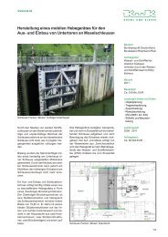
Fig.1 gives an aerial view <strong>of</strong> <strong>the</strong> sport area. <strong>The</strong> stadium oval is <strong>in</strong>terrupted by <strong>the</strong> Marathon gate allow<strong>in</strong>g <strong>the</strong> Bell<br />
tower to be seen from <strong>in</strong>side <strong>the</strong> stadium (Fig.2).<strong>The</strong> oval is 300 m long, 215 m wide and <strong>the</strong> grandstand has a<br />
maximum height <strong>of</strong> 15 m above <strong>the</strong> surro<strong>und</strong><strong>in</strong>g gro<strong>und</strong>. <strong>The</strong> upper and lower terraces are separated by a <strong>in</strong>ner<br />
gallery (Fig. 3).<strong>The</strong> grandstand was built with re<strong>in</strong>forced concrete (prefabricated step units and cast-<strong>in</strong>-place radial<br />
frames, Fig.4). <strong>The</strong> columns <strong>of</strong> <strong>the</strong> outer and <strong>the</strong> <strong>in</strong>ner galleries are made <strong>of</strong> stone blocks.<br />
Fig.1.View <strong>of</strong> <strong>the</strong> <strong>Olympic</strong> Park from 1933. Fig.2. Marathon Gate with view <strong>of</strong> <strong>the</strong> Bell tower<br />
.<br />
Fig. 3 View <strong>of</strong> <strong>the</strong> stadium from <strong>the</strong> circumferential <strong>in</strong>ner gallery.<br />
1
<strong>The</strong> upper and <strong>the</strong> lower terraces are structurally completely <strong>in</strong>dependent from each o<strong>the</strong>r. In tangential direction<br />
dilatation jo<strong>in</strong>ts were provided every 3 or 4 radial frames (i.e. at a distance <strong>of</strong> 15 to 20 m); <strong>the</strong>y were realised by<br />
us<strong>in</strong>g brackets. Most <strong>of</strong> <strong>the</strong> damages that occurred with<strong>in</strong> <strong>the</strong> re<strong>in</strong>forced concrete construction dur<strong>in</strong>g <strong>the</strong> 65 years<br />
were located at <strong>the</strong>se jo<strong>in</strong>ts.<br />
In preparation for <strong>the</strong> World Football Championship from 1974 <strong>the</strong> two ma<strong>in</strong> opposite grandstands were partially<br />
ro<strong>of</strong>ed with a MERO system (Fig.5). <strong>The</strong> ro<strong>of</strong> was carried by very slender massive steel columns placed <strong>in</strong>side <strong>the</strong><br />
upper terrace and by <strong>the</strong> exist<strong>in</strong>g outer stone columns. Steel anchors had been bored <strong>in</strong>side <strong>the</strong> stone columns <strong>in</strong><br />
order to be able to balance <strong>the</strong> tension forces from <strong>the</strong> ro<strong>of</strong> by activat<strong>in</strong>g <strong>the</strong> self-weight <strong>of</strong> <strong>the</strong> outer gallery.<br />
Fig. 4. <strong>The</strong> grandstand and <strong>the</strong> structural model <strong>of</strong> <strong>the</strong> upper terrace [3].<br />
Fig.5 <strong>The</strong> ro<strong>of</strong> from 1974 and <strong>the</strong> load carry<strong>in</strong>g system.<br />
Due to its <strong>in</strong>appropriate state <strong>the</strong> stadium could not have been used properly for <strong>the</strong> world event from 2006. Indeed<br />
<strong>the</strong> construction <strong>of</strong> <strong>the</strong> grandstand was <strong>in</strong> a very poor condition with large zones <strong>of</strong> re<strong>in</strong>forcement bars without<br />
concrete cover and serious damages <strong>of</strong> <strong>the</strong> concrete and stone parts. Fur<strong>the</strong>r <strong>the</strong> new FIFA regulations require a<br />
complete ro<strong>of</strong><strong>in</strong>g <strong>of</strong> <strong>the</strong> terraces. Consequently <strong>the</strong> city council <strong>of</strong> Berl<strong>in</strong> decided <strong>in</strong> 1998 to completely retr<strong>of</strong>it and<br />
modernise <strong>the</strong> stadium; <strong>the</strong> re<strong>in</strong>forced concrete and <strong>the</strong> stone construction were to be completely restored, <strong>the</strong> old<br />
partial ro<strong>of</strong> from 1974 was to be replaced by a complete ro<strong>of</strong><strong>in</strong>g <strong>of</strong> <strong>the</strong> whole spectator area, new premises <strong>in</strong>side<br />
<strong>the</strong> grandstands as well as constructions outside were to be realised, to optimally accommodate <strong>the</strong> multiple<br />
2
functions <strong>of</strong> a modern sport arena. An architectural contest was called upon. <strong>The</strong> call <strong>of</strong> tender particularly specified,<br />
that <strong>the</strong> new concept should preserve as much as possible from <strong>the</strong> historical appearance <strong>of</strong> <strong>the</strong> stadium and that a<br />
special attention should be given to <strong>the</strong> ma<strong>in</strong> architectural features <strong>of</strong> <strong>the</strong> complex with its pregnant east-west axis<br />
(conta<strong>in</strong><strong>in</strong>g <strong>the</strong> Marathon gate and <strong>the</strong> Bell tower). Fur<strong>the</strong>rmore <strong>the</strong> construction work had to take place without any<br />
<strong>in</strong>terruption <strong>of</strong> <strong>the</strong> sport activities but <strong>the</strong> normal seasonal pauses.<br />
Ten teams participated to <strong>the</strong> contest. W<strong>in</strong>ner was a team led by <strong>the</strong> famous German architects von Gerkan, Marg<br />
and Partners [4],[5]. Structural eng<strong>in</strong>eers were <strong>Krebs</strong> & <strong>Kiefer</strong> Consult<strong>in</strong>g Eng<strong>in</strong>eers [6].<br />
<strong>The</strong> w<strong>in</strong>ner’s design concept <strong>in</strong>cluded a complete new ro<strong>of</strong>, a complete retr<strong>of</strong>itt<strong>in</strong>g <strong>of</strong> <strong>the</strong> upper terrace with added<br />
structural elements to carry <strong>the</strong> ro<strong>of</strong>, <strong>the</strong> replacement <strong>of</strong> <strong>the</strong> lower terrace through a new construction, <strong>the</strong> lower<strong>in</strong>g<br />
<strong>of</strong> <strong>the</strong> sports gro<strong>und</strong> by 2,65 m with a new construction <strong>of</strong> <strong>the</strong> reporter trench , <strong>the</strong> extension <strong>of</strong> <strong>the</strong> 1st basement<br />
over <strong>the</strong> whole circumference <strong>of</strong> <strong>the</strong> stadium with new constructions outside <strong>the</strong> stadium to accommodate different<br />
functions. <strong>The</strong> total costs were expected to be about 270 Millions Euro. A major role <strong>in</strong> <strong>the</strong> jury decision for <strong>the</strong><br />
w<strong>in</strong>n<strong>in</strong>g concept has played <strong>the</strong> design <strong>of</strong> <strong>the</strong> new ro<strong>of</strong>. Its structural concept and construction are presented with<strong>in</strong><br />
this paper.<br />
2. THE STRUCTURAL CONCEPT<br />
<strong>The</strong> choice <strong>of</strong> <strong>the</strong> structural system was crucially <strong>in</strong>fluenced by <strong>the</strong> three requirements set by <strong>the</strong> client, i.e. (i) keep<br />
<strong>the</strong> Marathon gate open to allow a free view from <strong>in</strong>side <strong>the</strong> stadium towards <strong>the</strong> Bell tower, (ii) design a ro<strong>of</strong> which<br />
will optically not affect <strong>the</strong> outside appearance <strong>of</strong> <strong>the</strong> stadium and (iii) make possible <strong>the</strong> erection <strong>of</strong> <strong>the</strong> ro<strong>of</strong> without<br />
any <strong>in</strong>terruption <strong>of</strong> <strong>the</strong> sport activities. On <strong>the</strong>se accounts we have decided to give up any concept <strong>of</strong> a suspended<br />
ro<strong>of</strong>. Such a ro<strong>of</strong> would have needed closed outer and <strong>in</strong>ner r<strong>in</strong>gs which had impeded <strong>the</strong> view from stadium<br />
through <strong>the</strong> Marathon gate even if <strong>the</strong> ro<strong>of</strong><strong>in</strong>g itself were to be <strong>in</strong>terrupted <strong>the</strong>re. Fur<strong>the</strong>rmore ei<strong>the</strong>r <strong>of</strong> <strong>the</strong> two<br />
possible suspended ro<strong>of</strong> systems have had also o<strong>the</strong>r <strong>in</strong>conveniences. <strong>The</strong> one system with two outer compressed<br />
r<strong>in</strong>gs had needed a height (distance between <strong>the</strong> upper and lower r<strong>in</strong>g) <strong>of</strong> at least 25 m, which was not to be<br />
overseen from outside <strong>the</strong> stadium <strong>The</strong> o<strong>the</strong>r system with only one outer compressive r<strong>in</strong>g had needed a similar<br />
height between <strong>the</strong> two tensile r<strong>in</strong>gs situated at <strong>the</strong> <strong>in</strong>terior <strong>of</strong> <strong>the</strong> stadium and <strong>the</strong>refore <strong>the</strong> lower cable grid could<br />
have had impeded <strong>the</strong> view from one upper terrace to <strong>the</strong> opposite, if <strong>the</strong> outer compressive r<strong>in</strong>g were to be placed<br />
not too high above <strong>the</strong> attic <strong>of</strong> <strong>the</strong> stadium.<br />
<strong>The</strong> structural system that we have f<strong>in</strong>ally chosen is depicted <strong>in</strong> Fig.6. <strong>The</strong> steel structure is a spatial truss<br />
Fig.6 <strong>The</strong> chosen structure<br />
3
susta<strong>in</strong>ed by <strong>in</strong>ner and outer columns. <strong>The</strong> length <strong>of</strong> <strong>the</strong> ro<strong>of</strong> <strong>in</strong> radial direction is about 68 m. <strong>The</strong> lay-out <strong>in</strong>-plane<br />
has <strong>the</strong> shape <strong>of</strong> a horse shoe, <strong>the</strong>re is no ro<strong>of</strong> above <strong>the</strong> Marathon gate. <strong>The</strong> total ro<strong>of</strong>ed area is about 43300 m 2<br />
Plac<strong>in</strong>g <strong>the</strong> <strong>in</strong>ner column with<strong>in</strong> <strong>the</strong> upper terrace was not only an unorthodox decision for a modern stadium but<br />
also a very risky one <strong>in</strong> view <strong>of</strong> <strong>the</strong> possible verdict <strong>of</strong> <strong>the</strong> jury. It has been however taken after carefully analys<strong>in</strong>g<br />
<strong>the</strong> pros and contras.<br />
<strong>The</strong> advantages were<br />
(i) <strong>the</strong> ro<strong>of</strong> will hardly be perceived from outside if it has a sharp edge only few meters above <strong>the</strong><br />
stadium attic,<br />
(ii) <strong>the</strong>re is no problem to <strong>in</strong>terrupt <strong>the</strong> ro<strong>of</strong> at <strong>the</strong> Marathon gate, so that <strong>the</strong> view towards Bell tower will<br />
rema<strong>in</strong> completely free,<br />
(iii) it is possible to build <strong>the</strong> ro<strong>of</strong> sequentially, so that <strong>the</strong>re will be no disruption <strong>of</strong> <strong>the</strong> sport activities.<br />
With respect to <strong>the</strong> disadvantage <strong>of</strong> hav<strong>in</strong>g columns with<strong>in</strong> <strong>the</strong> grandstand studies carried out by <strong>the</strong> architects have<br />
shown that <strong>the</strong> <strong>in</strong>ner columns were less h<strong>in</strong>der<strong>in</strong>g as <strong>in</strong>itially feared. Of course <strong>the</strong> number and <strong>the</strong> diameter <strong>of</strong><br />
<strong>the</strong>se columns were to be reduced as much as possible. Prelim<strong>in</strong>ary calculations have shown that <strong>the</strong> ro<strong>of</strong> can be<br />
susta<strong>in</strong>ed with 20 steel columns hav<strong>in</strong>g a diameter <strong>of</strong> ca 27cm. <strong>The</strong> <strong>in</strong>itial concept has foreseen an <strong>in</strong>cl<strong>in</strong>ed <strong>in</strong>ner<br />
column.<br />
<strong>The</strong> <strong>in</strong>cl<strong>in</strong>ation has had advantages from both architectural and structural po<strong>in</strong>t <strong>of</strong> view: from <strong>the</strong> architectural<br />
because it had brought a certa<strong>in</strong> dynamic to <strong>the</strong> whole concept, <strong>the</strong> columns have had looked like ‘hands’ carry<strong>in</strong>g<br />
<strong>the</strong> ro<strong>of</strong>, from <strong>the</strong> structural because <strong>the</strong> cantilever span could have hence been reduced. However <strong>the</strong> <strong>in</strong>cl<strong>in</strong>ation<br />
<strong>of</strong> <strong>the</strong> <strong>in</strong>ner column yields an horizontal reaction force even <strong>und</strong>er vertical load<strong>in</strong>g (Fig.7a). <strong>The</strong> result<strong>in</strong>g<br />
compressive force between <strong>the</strong> two supports could not be carried by <strong>the</strong> exist<strong>in</strong>g <strong>in</strong>cl<strong>in</strong>ed beam <strong>of</strong> <strong>the</strong> terrace<br />
frame, so that it would had to be streng<strong>the</strong>ned. On <strong>the</strong> o<strong>the</strong>r hand <strong>the</strong> outer columns have had to carry larger<br />
bend<strong>in</strong>g moments. Hence to avoid large changes with<strong>in</strong> <strong>the</strong> exist<strong>in</strong>g construction and to keep <strong>the</strong> outer columns<br />
slender it was f<strong>in</strong>ally decided to design a vertical <strong>in</strong>ner column.<br />
a b c<br />
Fig.7 Reaction forces <strong>und</strong>er vertical loads by an <strong>in</strong>cl<strong>in</strong>ed <strong>in</strong>ner column (a) and by a vertical one (b)<br />
as well <strong>und</strong>er horizontal loads (c).<br />
<strong>The</strong> design concept has follow<strong>in</strong>g additional features (see Fig.6)..<br />
(1) <strong>The</strong> ro<strong>of</strong><strong>in</strong>g comprises two textile membranes placed above and beneath <strong>the</strong> steel structure. <strong>The</strong> upper<br />
membrane carries <strong>the</strong> snow and protect aga<strong>in</strong>st ra<strong>in</strong>. <strong>The</strong> slight <strong>in</strong>cl<strong>in</strong>ation <strong>of</strong> <strong>the</strong> upper flange <strong>of</strong> <strong>the</strong> steel truss<br />
towards outside allows a natural dra<strong>in</strong>age. <strong>The</strong> lower membrane acts as a ceil<strong>in</strong>g: a huge w<strong>in</strong>g-shaped box is<br />
<strong>the</strong>refore created <strong>in</strong> which both structure and <strong>the</strong> necessary technical equipment could be <strong>in</strong>corporated.<br />
(2) <strong>The</strong> outer side <strong>of</strong> <strong>the</strong> ro<strong>of</strong> is designed as a triangular-shaped box. <strong>The</strong> sharp exterior edge has <strong>the</strong> effect that<br />
<strong>the</strong> ro<strong>of</strong> appears from outside as a l<strong>in</strong>e float<strong>in</strong>g above <strong>the</strong> facade. In order to <strong>und</strong>erl<strong>in</strong>e this effect and also to<br />
create a surface reflect<strong>in</strong>g light dur<strong>in</strong>g <strong>the</strong> nocturnal activities <strong>in</strong>side <strong>the</strong> stadium, it was decided to cover <strong>the</strong><br />
4<br />
3D-Support
lower side <strong>of</strong> <strong>the</strong> box with metal. <strong>The</strong> box has also an important structural role. Its weight was to be so<br />
optimised that <strong>the</strong> result<strong>in</strong>g compression <strong>in</strong> <strong>the</strong> exist<strong>in</strong>g stone columns could balance <strong>the</strong> maximal tensile force<br />
yielded by <strong>the</strong> ro<strong>of</strong> (Fig.7b).<br />
(3) <strong>The</strong> outer columns were placed above every facade column. <strong>The</strong>y were to be very slender to have a m<strong>in</strong>imum<br />
impact on <strong>the</strong> outside view <strong>of</strong> <strong>the</strong> stadium.<br />
(4) <strong>The</strong> <strong>in</strong>ner side <strong>of</strong> <strong>the</strong> ro<strong>of</strong> is designed as a glass surface susta<strong>in</strong>ed by a visible ‘Vierendeel’ girder made <strong>of</strong> cast<br />
steel. <strong>The</strong> result<strong>in</strong>g height at <strong>the</strong> jo<strong>in</strong>t between <strong>the</strong> glass ro<strong>of</strong> and <strong>the</strong> double membrane made possible <strong>the</strong><br />
realisation <strong>of</strong> a catwalk along <strong>the</strong> whole ro<strong>of</strong> perimeter, <strong>in</strong> which <strong>the</strong> nocturnal lighten<strong>in</strong>g <strong>of</strong> <strong>the</strong> sport gro<strong>und</strong> as<br />
well as o<strong>the</strong>r technical equipment were to be accommodated.<br />
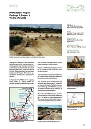
<strong>The</strong> f<strong>in</strong>al design concept as prepared by <strong>the</strong> architects and presented to <strong>the</strong> contest is shown <strong>in</strong> Fig. 8 and 9.<br />
Fig.8. Views <strong>of</strong> <strong>the</strong> stadium (models).<br />
Fig.9. Views <strong>of</strong> <strong>the</strong> stadium without ro<strong>of</strong> (a) and with <strong>the</strong> new ro<strong>of</strong> (b)<br />
3. THE STRUCTURAL DESIGN<br />
<strong>The</strong> structural system and components are depicted <strong>in</strong> Fig. 10. <strong>The</strong>re are tubular radial and tangential truss girders<br />
with welded nodes. <strong>The</strong>re are 76 radial truss girders, i.e. one for every two stone facade columns. <strong>The</strong>y are vertical<br />
two-flange trusses and are carried by two tangential members: a spatial, three-flange truss susta<strong>in</strong>ed by <strong>the</strong> treed<br />
<strong>in</strong>ner columns and an outer spatial beam susta<strong>in</strong>ed by <strong>the</strong> outer columns. Fur<strong>the</strong>r <strong>the</strong>re are two o<strong>the</strong>r tangential<br />
structural members. At <strong>the</strong> side <strong>of</strong> <strong>the</strong> ro<strong>of</strong> <strong>in</strong> <strong>the</strong> vic<strong>in</strong>ity <strong>of</strong> <strong>the</strong> jo<strong>in</strong>t between <strong>the</strong> membrane and <strong>the</strong> glass surfaces<br />
<strong>the</strong>re is an <strong>in</strong>cl<strong>in</strong>ed two-flange truss, which has <strong>the</strong> role <strong>of</strong> equalis<strong>in</strong>g <strong>the</strong> vertical displacements at <strong>the</strong> ends <strong>of</strong> <strong>the</strong><br />
radial girders. In between <strong>the</strong> described members <strong>the</strong>re are tangential tubular bars l<strong>in</strong>k<strong>in</strong>g <strong>the</strong> upper nodes <strong>of</strong> <strong>the</strong><br />
radial girders and respectively <strong>the</strong> lower nodes. <strong>The</strong>ir role is to stabilise <strong>the</strong> radial girders by carry<strong>in</strong>g <strong>the</strong> horizontal<br />
tangential forces to <strong>the</strong> brac<strong>in</strong>g. All bars with <strong>the</strong> exception <strong>of</strong> <strong>the</strong> lower flange <strong>of</strong> <strong>the</strong> radial truss over <strong>the</strong> bright <strong>of</strong><br />
5<br />
a<br />
b
<strong>the</strong> three flange tangential truss are straight. <strong>The</strong> curved lower flange <strong>of</strong> <strong>the</strong> radial truss is stabilised vertically by<br />
means <strong>of</strong> a steel cable (see Fig.6).<br />
Fig.10. Detail from <strong>the</strong> computational model <strong>of</strong> <strong>the</strong> structure [8].<br />
<strong>The</strong> radial truss has a maximal height <strong>of</strong> 5.5 m and its cantilever span is about 49 m. <strong>The</strong> radial distance between<br />
<strong>the</strong> <strong>in</strong>ner and <strong>the</strong> outer columns is about 17.5 m. <strong>The</strong> distance between <strong>the</strong> <strong>in</strong>ner columns <strong>in</strong> tangential direction<br />
varies between 32 and 40 m. <strong>The</strong> nodes <strong>of</strong> <strong>the</strong> tangential truss are cast. <strong>The</strong> <strong>in</strong>ner column has to carry a maximal<br />
force <strong>of</strong> 12 MN. Its vertical branch has a length <strong>of</strong> 8,5 m and a diameter vary<strong>in</strong>g from 250 mm (lower end) to 350<br />
mm; its cross section is massive and made <strong>of</strong> a high strength forg<strong>in</strong>g steel. <strong>The</strong> four <strong>in</strong>cl<strong>in</strong>ed branches <strong>of</strong> <strong>the</strong> <strong>in</strong>ner<br />
column have a massive diameter <strong>of</strong> 290 mm <strong>The</strong> node between <strong>the</strong> vertical and <strong>the</strong> <strong>in</strong>cl<strong>in</strong>ed branches are made <strong>of</strong><br />
high strength cast steel.<br />
<strong>The</strong> outer beam with triangular cross-section has a width <strong>of</strong> 8.5 m and is made <strong>of</strong> re<strong>in</strong>forced concrete partially<br />
prefabricated. In <strong>the</strong> vic<strong>in</strong>ity <strong>of</strong> <strong>the</strong> radius conta<strong>in</strong><strong>in</strong>g an <strong>in</strong>ner column <strong>the</strong> triangular cross-section is full, <strong>in</strong> order to<br />
become enough weight to balance <strong>the</strong> tensile reaction force.<br />
<strong>The</strong> horizontal stiffen<strong>in</strong>g <strong>in</strong> radial direction is realised by means <strong>of</strong> <strong>the</strong> frames made <strong>of</strong> an <strong>in</strong>ner column, <strong>the</strong> two<br />
correspond<strong>in</strong>g radial trusses and <strong>the</strong> four correspond<strong>in</strong>g outer columns (see Fig.10). 20 radial frames are available.<br />
In tangential direction <strong>the</strong>re are two framed l<strong>in</strong>es available: <strong>the</strong> one made <strong>of</strong> <strong>the</strong> <strong>in</strong>ner columns and <strong>the</strong> spatial<br />
tangential truss, <strong>the</strong> o<strong>the</strong>r made <strong>of</strong> <strong>the</strong> outer beam and <strong>the</strong> outer columns. Additional braces are necessary <strong>in</strong><br />
tangential direction to horizontally stiffen <strong>the</strong> ro<strong>of</strong>. <strong>The</strong>ir location is dependent on <strong>the</strong> dilatation jo<strong>in</strong>t which were<br />
provided <strong>in</strong> order to reduce <strong>the</strong> <strong>in</strong>ternal forces caused by <strong>the</strong> deformation <strong>und</strong>er temperature variation <strong>The</strong> position<br />
<strong>of</strong> <strong>the</strong> dilatation jo<strong>in</strong>t and <strong>of</strong> <strong>the</strong> braces is depicted <strong>in</strong> Fig.11. <strong>The</strong> outer beam is built cont<strong>in</strong>uously (without any jo<strong>in</strong>t)<br />
over <strong>the</strong> whole perimeter <strong>of</strong> <strong>the</strong> stadium. <strong>The</strong>re are three dilatation jo<strong>in</strong>ts <strong>in</strong>side <strong>the</strong> range between <strong>the</strong> outer beam<br />
and <strong>the</strong> tangential <strong>in</strong>-plane (two flanged) truss at <strong>the</strong> tip <strong>of</strong> <strong>the</strong> radial trusses and <strong>the</strong>re are six dilatation jo<strong>in</strong>ts <strong>in</strong>side<br />
<strong>the</strong> range made with glass. This range is stiffened <strong>in</strong> tangential direction by <strong>the</strong> horizontal frame made <strong>of</strong> <strong>the</strong> radial<br />
and tangential girders. Consequently only <strong>the</strong> middle ranges between <strong>the</strong> three dilation jo<strong>in</strong>ts are to be stiffened .<strong>in</strong><br />
tangential direction. Four braces are necessary. <strong>The</strong>ir location is depicted <strong>in</strong> Fig.11. Each brace uses two radial<br />
trusses adjacent to an <strong>in</strong>ner column as flanges, while diagonal bars l<strong>in</strong>k <strong>the</strong> upper nodes <strong>of</strong> one girder with <strong>the</strong><br />
lower nodes <strong>of</strong> <strong>the</strong> o<strong>the</strong>r <strong>in</strong> an alternat<strong>in</strong>g way. <strong>The</strong> diagonal bars are designed as tensile members and are made<br />
<strong>of</strong> pre-stressed high-strength ro<strong>und</strong> bars. This concept orig<strong>in</strong>ates from <strong>the</strong> architect’s wish to become a regular<br />
rectangular grid <strong>of</strong> <strong>the</strong> structure to be seen through <strong>the</strong> lower textile membrane - see Fig. 12.<br />
6
Fig..11. <strong>The</strong> dilatation jo<strong>in</strong>ts and <strong>the</strong> tangential brac<strong>in</strong>g. Fig.12. View <strong>of</strong> <strong>the</strong> ro<strong>of</strong> from beneath.<br />
<strong>The</strong> ro<strong>of</strong> reaction forces had to be fur<strong>the</strong>r carried through an exist<strong>in</strong>g construction which was made <strong>of</strong> a very poor<br />
concrete. Indeed measurements <strong>of</strong> <strong>the</strong> concrete strength have shown values between 5 and 25 MPa (Fig.13).<br />
Moreover <strong>the</strong>re were no re<strong>in</strong>forcement draw<strong>in</strong>gs available. Consequently it has been decided to use <strong>the</strong> exist<strong>in</strong>g<br />
construction for carry<strong>in</strong>g – as before – only <strong>the</strong> loads com<strong>in</strong>g from <strong>the</strong> grandstand itself and to design a new system<br />
for <strong>the</strong> loads <strong>in</strong>duced by <strong>the</strong> ro<strong>of</strong>. This new structural system had to be <strong>in</strong>dependent <strong>of</strong> <strong>the</strong> exist<strong>in</strong>g grandstand or<br />
modify it as few as possible bear<strong>in</strong>g <strong>in</strong> m<strong>in</strong>d that <strong>the</strong> stadium is a protected architectural monument. <strong>The</strong> structural<br />
concept <strong>of</strong> this system is shown <strong>in</strong> Fig.7c. It is a statically determ<strong>in</strong>ate system. Its construction is depicted <strong>in</strong> Fig.<br />
14. It is made <strong>of</strong> re<strong>in</strong>forced concrete and consists <strong>of</strong> <strong>the</strong> follow<strong>in</strong>g parts.<br />
Fig.13. Measured concrete strength [7] Fig.14. <strong>The</strong> structural system carry<strong>in</strong>g <strong>the</strong> ro<strong>of</strong> loads<br />
(i) <strong>The</strong> ma<strong>in</strong> structural part is a spatial frame with four columns <strong>in</strong> <strong>the</strong> axes C and D, which has <strong>the</strong> role <strong>of</strong> carry<strong>in</strong>g<br />
<strong>the</strong> vertical loads from <strong>the</strong> <strong>in</strong>ner column and <strong>the</strong> horizontal loads <strong>in</strong> radial direction. At <strong>the</strong> same time it represents<br />
one <strong>of</strong> <strong>the</strong> two supports for <strong>the</strong> horizontal loads <strong>in</strong> tangential direction. <strong>The</strong> concept <strong>of</strong> this frame has also had to<br />
take <strong>in</strong>to consideration that <strong>the</strong>re are different situations with<strong>in</strong> <strong>the</strong> grandstand to cope with. For <strong>in</strong>stance at certa<strong>in</strong><br />
locations <strong>the</strong> <strong>in</strong>ner column had to be supported vertically by a beam s<strong>in</strong>ce o<strong>the</strong>rwise it would go through a corridor<br />
l<strong>in</strong>k<strong>in</strong>g <strong>the</strong> <strong>in</strong>ner and <strong>the</strong> outer galleries.<br />
(ii) <strong>The</strong> second support for <strong>the</strong> horizontal loads <strong>in</strong> tangential direction is provided by structural walls <strong>in</strong> axis B. <strong>The</strong>se<br />
walls are cast-<strong>in</strong> at <strong>the</strong> <strong>in</strong>ner face <strong>of</strong> <strong>the</strong> exist<strong>in</strong>g façade.<br />
(iii) To carry <strong>the</strong> horizontal reaction forces <strong>in</strong> radial direction from <strong>the</strong> outer column to <strong>the</strong> spatial frame described<br />
<strong>und</strong>er (i) parts <strong>of</strong> <strong>the</strong> exist<strong>in</strong>g <strong>in</strong>cl<strong>in</strong>ed diaphragm between <strong>the</strong> axes A and B (monolithic terrace) was completely<br />
7
new replaced and additionally a new l<strong>in</strong>k between <strong>the</strong> axes B and D <strong>und</strong>erneath <strong>the</strong> terrace units had to be built.<br />
(iv) Above <strong>the</strong> exist<strong>in</strong>g stone columns <strong>in</strong> <strong>the</strong> facade and <strong>in</strong>side <strong>the</strong> stone attic beam a new re<strong>in</strong>forced concrete<br />
beam was cast. Its role is to distribute <strong>the</strong> horizontal tangential force com<strong>in</strong>g from <strong>the</strong> outer ro<strong>of</strong> columns to <strong>the</strong><br />
diaphragm described <strong>und</strong>er (iii). At <strong>the</strong> same time it was possible to cast-<strong>in</strong> <strong>the</strong> supports <strong>of</strong> <strong>the</strong> outer ro<strong>of</strong> columns<br />
<strong>in</strong> this beam. Fur<strong>the</strong>rmore a special attention has to be paid to <strong>the</strong> dilatation jo<strong>in</strong>ts with<strong>in</strong> this beam s<strong>in</strong>ce <strong>the</strong> beam<br />
crosses many <strong>of</strong> <strong>the</strong> dilatation jo<strong>in</strong>ts exist<strong>in</strong>g <strong>in</strong> <strong>the</strong> old construction <strong>of</strong> <strong>the</strong> grandstand.<br />
4. THE STRUCTURAL ANALYSIS AND CONSTRUCTION<br />
<strong>The</strong> structure was analysed by means <strong>of</strong> a complete 3D model <strong>of</strong> <strong>the</strong> ro<strong>of</strong> (see Fig. 10). <strong>The</strong> w<strong>in</strong>d loads were<br />
determ<strong>in</strong>ed by test<strong>in</strong>g a model <strong>in</strong> a w<strong>in</strong>d tunnel and numerically evaluat<strong>in</strong>g <strong>the</strong> gust factors. <strong>The</strong> first period <strong>of</strong><br />
vibration is about 3 s and <strong>the</strong> correspond<strong>in</strong>g form is a general horizontal rotation about <strong>the</strong> central vertical axis <strong>of</strong><br />
<strong>the</strong> whole ro<strong>of</strong>. <strong>The</strong> gust factors are 1,3 for <strong>the</strong> horizontal and 1,1 for <strong>the</strong> vertical w<strong>in</strong>d forces while <strong>the</strong> static w<strong>in</strong>d<br />
pressure is about 1.25 kN/m 2 . <strong>The</strong> vertical displacement at <strong>the</strong> <strong>in</strong>ner end <strong>of</strong> <strong>the</strong> ro<strong>of</strong> <strong>und</strong>er snow is about 25 mm.<br />
<strong>The</strong> computed relative displacements <strong>in</strong> <strong>the</strong> ro<strong>of</strong> jo<strong>in</strong>ts <strong>und</strong>er a temperature variation <strong>of</strong> 35 o Care60mm<strong>in</strong><strong>the</strong><br />
middle jo<strong>in</strong>ts and 35 mm <strong>in</strong> <strong>the</strong> jo<strong>in</strong>ts with<strong>in</strong> <strong>the</strong> glass construction (see Fig. 11). On account <strong>of</strong> <strong>the</strong> column<br />
slenderness <strong>the</strong>re are very small <strong>in</strong>ternal forces to occur from <strong>the</strong> different deformations <strong>of</strong> <strong>the</strong> ro<strong>of</strong> and <strong>the</strong><br />
grandstand [8].<br />
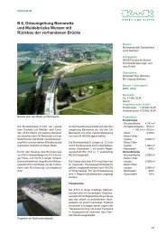
<strong>The</strong> erection <strong>of</strong> <strong>the</strong> steel structure has always started at a radius with <strong>in</strong>ner column. Follow<strong>in</strong>g steps were used.<br />
Firstly came <strong>the</strong> outer columns and <strong>the</strong> steel and pre-cast R/C elements <strong>of</strong> <strong>the</strong> perimeter beam. <strong>The</strong> <strong>in</strong>ner column<br />
was <strong>the</strong>n erected and temporarily supported. Afterwards <strong>the</strong> assembly made by <strong>the</strong> parts <strong>of</strong> <strong>the</strong> radial trusses<br />
adjacent to <strong>the</strong> <strong>in</strong>ner column and ly<strong>in</strong>g between this column and <strong>the</strong> outer beam was erected. All spatial parts were<br />
welded outside <strong>the</strong> stadium and were already equipped with <strong>the</strong> steel arches, which had to carry <strong>the</strong> upper textile<br />
membrane (Fig.15). At this stage <strong>the</strong> structure became self stabilized, <strong>the</strong>re was no longer need for <strong>the</strong> temporary<br />
support <strong>of</strong> <strong>the</strong> <strong>in</strong>ner column. After ballast<strong>in</strong>g <strong>of</strong> <strong>the</strong> outer beam <strong>the</strong> erection cont<strong>in</strong>ued with <strong>the</strong> tangential spatial<br />
truss l<strong>in</strong>k<strong>in</strong>g <strong>the</strong> <strong>in</strong>ner columns, <strong>the</strong> rests <strong>of</strong> <strong>the</strong> radial and tangential steel structure and so on.<br />
Fig.15. Erection <strong>of</strong> <strong>the</strong> steel structure Fig. 16. Detail <strong>of</strong> <strong>the</strong> outer beam before ballast<strong>in</strong>g<br />
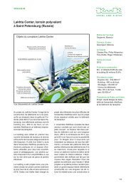
<strong>The</strong> textile membranes were designed by <strong>the</strong> consultant civil eng<strong>in</strong>eers Schlaich, Bergermann and Partners [9].<br />
<strong>The</strong> upper membrane is supported by steel arches and has a double negative curvature (Fig. 17). <strong>The</strong> lower<br />
membrane is open on <strong>the</strong> perimeter, plane and pre-stressed by means <strong>of</strong> small spr<strong>in</strong>gs (Fig. 18). A detailed<br />
description <strong>of</strong> <strong>the</strong> ro<strong>of</strong> construction is given <strong>in</strong> [10].<br />
Follow<strong>in</strong>g German companies were <strong>in</strong>volved with <strong>the</strong> design and erection <strong>of</strong> <strong>the</strong> ro<strong>of</strong>: von Gerkan, Marg and<br />
Partners (gmp) as architects, <strong>Krebs</strong> & <strong>Kiefer</strong> Consult<strong>in</strong>g Eng<strong>in</strong>eers Ltd as structural eng<strong>in</strong>eers, Schlaich,<br />
8
Bergermann and Partners as designer <strong>of</strong> <strong>the</strong> membrane ro<strong>of</strong><strong>in</strong>g and <strong>of</strong> some cast nodes, Wacker Eng<strong>in</strong>eers and<br />
Institute for Industry Aerodynamic Aachen for <strong>the</strong> W<strong>in</strong>d Eng<strong>in</strong>eer<strong>in</strong>g, Institute <strong>of</strong> Steel Construction (University <strong>of</strong><br />
Aachen) as expert for special steel, Dill<strong>in</strong>ger Stahlbau Ltd for <strong>the</strong> steel construction, B&O Hightex Ltd for <strong>the</strong><br />
membrane construction, MERO Ltd for <strong>the</strong> glass construction and Pr<strong>of</strong>. M. Specht as pro<strong>of</strong> eng<strong>in</strong>eer. For <strong>the</strong><br />
design <strong>of</strong> <strong>the</strong> ro<strong>of</strong> gmp and <strong>Krebs</strong> & <strong>Kiefer</strong> have received <strong>the</strong> Special Award <strong>of</strong> <strong>the</strong> German Association <strong>of</strong> Steel<br />
Construction 2004.<br />
With<strong>in</strong> <strong>the</strong> design team <strong>of</strong> <strong>Krebs</strong> & <strong>Kiefer</strong> <strong>the</strong> ma<strong>in</strong> technical responsibilities were ensured by <strong>the</strong> author (for<br />
architecture contest and prelim<strong>in</strong>ary design), by Dr. Stroetmann (for f<strong>in</strong>al design and structural analysis) and by Dr.<br />
<strong>Kiefer</strong> and H. Müller (for load carry<strong>in</strong>g structure <strong>in</strong>side <strong>the</strong> exist<strong>in</strong>g grandstand).<br />
Fig.17. <strong>The</strong> upper membrane. Fig.18. <strong>The</strong> lower membrane. (View <strong>in</strong>side <strong>the</strong> ro<strong>of</strong> box)<br />
REFERENCES<br />
[1] V. Kluge, Olympiastadion Berl<strong>in</strong> – Ste<strong>in</strong>e beg<strong>in</strong>nen zu reden, Parthas Verlag, Berl<strong>in</strong>, 1999.<br />
[2] W. Schäche, Von der Rennbahn bis zum Sportpark des 21. Jahrh<strong>und</strong>erts – Etappen e<strong>in</strong>er komplexen Baugeschichte.<br />
Panorama e<strong>in</strong>es Bauwerks – Olympiastadion Berl<strong>in</strong>, Jovis Verlag, Berl<strong>in</strong>, 2001.<br />
[3]W.Thieme,Eisenbetonbauten auf dem Reichssportfeld Berl<strong>in</strong>, ,Beton <strong>und</strong> Eisen, Nr. 5, pp. 73-77, März 1936.<br />
[4] V. Marg, <strong>Stadium</strong> Build<strong>in</strong>g: Orchestration and Experience <strong>of</strong> <strong>the</strong> Masses, Berl<strong>in</strong> <strong>Olympic</strong> <strong>Stadium</strong>, Renovation and<br />
Modernization 2000 – 2004 (editor V. Marg), pp.9-14, 2004<br />
[5] H. Nienh<strong>of</strong>f, H.W. Zopfy, An Interior Space <strong>und</strong>er <strong>the</strong> Open Sky, Berl<strong>in</strong> <strong>Olympic</strong> <strong>Stadium</strong>, Renovation and Modernization 2000<br />
– 2004 (editor V. Marg), pp.27-32, 2004<br />
[6] D. Constant<strong>in</strong>escu, R. Stroetmann, H. Müller, Die Modernisierung der Olympiastadion Berl<strong>in</strong> , Lectures at <strong>the</strong> Universities <strong>of</strong><br />
Karlsruhe (Febr.2001)and Darmstadt (July 2001).<br />
[7]D.Hanek,Tragwerksplanung für das neue Olympiastadion Berl<strong>in</strong>, Beratende Ingenieure, pp. 22-25, Oct. 2001.<br />
[8] R. Stroetmann, R. Schneider, Olympiastadion Berl<strong>in</strong> – Die neue Tribünenüberdachung, Stahlbau 72, No.4, pp.214-227, 2003.<br />
[9] K. Göppert, Membranentragwerke, Stahlbaukalender 2004, pp.703-740, Ernst & Sohn, 2004.<br />
[10] R. Stroetmann, Modernisierung <strong>und</strong> Instandsetzung des Berl<strong>in</strong>er Olympiastadions, Stahlbau Spezial 2005, pp.53-70<br />
Abbildungen <strong>und</strong> Fotos<br />
gmp Architekten von Gerkan, Marg <strong>und</strong> Partner Berl<strong>in</strong>; He<strong>in</strong>er Leiska Hamburg; <strong>Krebs</strong> <strong>und</strong> <strong>Kiefer</strong> Beratende Ingenieure für das<br />
Bauwesen GmbH<br />
Pr<strong>of</strong>. Dr.-Ing. Dan Constant<strong>in</strong>escu<br />
Born <strong>in</strong> 1940 <strong>in</strong> Bucharest, graduated <strong>the</strong> Faculty <strong>of</strong> Civil Eng<strong>in</strong>eer<strong>in</strong>g <strong>in</strong> Bucharest <strong>in</strong> 1963. Undertook a<br />
postgraduate study at K<strong>in</strong>g’ College London (1973-1976) and received <strong>the</strong> PhD degree <strong>in</strong> CEng from <strong>the</strong><br />
University <strong>of</strong> London. Between 1963 and 1985 was member <strong>of</strong> <strong>the</strong> academic staff <strong>of</strong> <strong>the</strong> Department <strong>of</strong><br />
Concrete Structures at <strong>the</strong> Faculty <strong>of</strong> Civil Eng<strong>in</strong>eer<strong>in</strong>g <strong>in</strong> Bucharest (s<strong>in</strong>ce 1977 as Associate Pr<strong>of</strong>essor).<br />
In Germany s<strong>in</strong>ce 1988. Honorary Pr<strong>of</strong>essor <strong>of</strong> <strong>the</strong> University <strong>of</strong> Darmstadt (Structural Dynamics and<br />
Earthquake Eng<strong>in</strong>eer<strong>in</strong>g). Partner and manager <strong>of</strong> <strong>Krebs</strong> & <strong>Kiefer</strong> Consultant Civil Eng<strong>in</strong>eers GmbH<br />
Karlsruhe. Pro<strong>of</strong> Eng<strong>in</strong>eer for both Concrete and Steel Structures.<br />
9
<strong>Krebs</strong> <strong>und</strong> <strong>Kiefer</strong><br />
Beratende Ingenieure<br />
für das Bauwesen GmbH,<br />
Berl<strong>in</strong><br />
Kochstraße 27<br />
10969 Berl<strong>in</strong><br />
Telefon (030) 21 73 42-0<br />
Telefax (030) 21 73 42-11<br />
kuk@b.kuk.de<br />
<strong>Krebs</strong> <strong>und</strong> <strong>Kiefer</strong><br />
Beratende Ingenieure<br />
für das Bauwesen GmbH,<br />
Darmstadt<br />
Hilpertstraße 20<br />
64295 Darmstadt<br />
Telefon (0 61 51) 885-0<br />
Telefax (0 61 51) 885-150<br />
kuk@da.kuk.de<br />
<strong>Krebs</strong> <strong>und</strong> <strong>Kiefer</strong><br />
Beratende Ingenieure<br />
für das Bauwesen GmbH,<br />
Erfurt<br />
Am Seegraben 2<br />
99099 Erfurt<br />
Telefon (03 611) 4 20 64-11<br />
Telefax (03 611) 4 20 64-12<br />
kuk@ef.kuk.de<br />
Besuchen Sie uns auch im Internet unter www.kuk.de<br />
<strong>Krebs</strong> <strong>und</strong> <strong>Kiefer</strong><br />
Beratende Ingenieure<br />
für das Bauwesen GmbH,<br />
Freiburg i. Br.<br />
Bertoldstraße 48<br />
79098 Freiburg i. Br.<br />
Telefon (07 61) 2 96 66-0<br />
Telefax (07 61) 2 96 66-50<br />
kuk@fr.kuk.de<br />
<strong>Krebs</strong> <strong>und</strong> <strong>Kiefer</strong><br />
Beratende Ingenieure<br />
für das Bauwesen GmbH,<br />
Karlsruhe<br />
Karlstraße 46<br />
76133 Karlsruhe<br />
Telefon (07 21) 35 08-0<br />
Telefax (07 21) 35 08-211<br />
kuk@ka.kuk.de