

remote axe 10 subscriber switch in a container an optical fibre line ...
remote axe 10 subscriber switch in a container an optical fibre line ...
remote axe 10 subscriber switch in a container an optical fibre line ...
- No tags were found...

You also want an ePaper? Increase the reach of your titles
YUMPU automatically turns print PDFs into web optimized ePapers that Google loves.
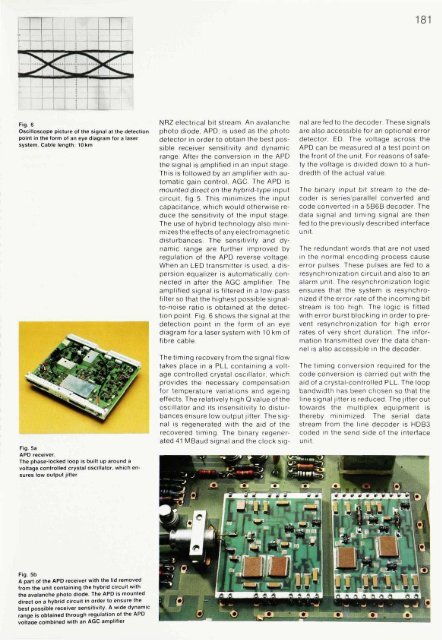
181Fig. 6Oscilloscope picture of the signal at the detectionpo<strong>in</strong>t <strong>in</strong> the form of <strong>an</strong> eye diagram tor a lasersystem. Cable length: <strong>10</strong>kmFig. 5aAPD receiver.The phase-locked loop is built up around avoltage controlled crystal oscillator, which ensureslow output jitterNRZ electrical bit stream. An aval<strong>an</strong>chephoto diode, APD, is used as the photodetector <strong>in</strong> order to obta<strong>in</strong> the best possiblereceiver sensitivity <strong>an</strong>d dynamicr<strong>an</strong>ge. After the conversion <strong>in</strong> the APDthe signal is amplified <strong>in</strong> <strong>an</strong> <strong>in</strong>put stage.This is followed by <strong>an</strong> amplifier with automaticga<strong>in</strong> control, AGC. The APD ismounted direct on the hybrid-type <strong>in</strong>putcircuit, fig.5. This m<strong>in</strong>imizes the <strong>in</strong>putcapacit<strong>an</strong>ce, which would otherwise reducethe sensitivity of the <strong>in</strong>put stageThe use of hybrid technology also m<strong>in</strong>imizesthe effects of <strong>an</strong>y electromagneticdisturb<strong>an</strong>ces. The sensitivity <strong>an</strong>d dynamicr<strong>an</strong>ge are further improved byregulation of the APD reverse voltage.When <strong>an</strong> LED tr<strong>an</strong>smitter is used, a dispersionequalizer is automatically connected<strong>in</strong> after the AGC amplifier Theamplified signal is filtered <strong>in</strong> a low-passfilter so that the highest possible signalto-noiseratio is obta<strong>in</strong>ed at the detectionpo<strong>in</strong>t. Fig. 6 shows the signal at thedetection po<strong>in</strong>t <strong>in</strong> the form of <strong>an</strong> eyediagram for a laser system with <strong>10</strong> km of<strong>fibre</strong> cable.The tim<strong>in</strong>g recovery from the signal flowtakes place <strong>in</strong> a PLL conta<strong>in</strong><strong>in</strong>g a voltagecontrolled crystal oscillator, whichprovides the necessary compensationfor temperature variations <strong>an</strong>d age<strong>in</strong>geffects. The relatively high Q value of theoscillator <strong>an</strong>d its <strong>in</strong>sensitivity to disturb<strong>an</strong>cesensure low output jitter. The signalis regenerated with the aid of therecovered tim<strong>in</strong>g. The b<strong>in</strong>ary regenerated41 MBaud signal <strong>an</strong>d the clock signalare fed to the decoder. These signalsare also accessible for <strong>an</strong> optional errordetector, ED The voltage across theAPD c<strong>an</strong> be measured at a test po<strong>in</strong>t onthe front of the unit. For reasons of safetythe voltage is divided down to a hundredthof the actual valueThe b<strong>in</strong>ary <strong>in</strong>put bit stream to the decoderis series/parallel converted <strong>an</strong>dcode converted <strong>in</strong> a 5B6B decoder. Thedata signal <strong>an</strong>d tim<strong>in</strong>g signal are thenfed to the previously described <strong>in</strong>terfaceunit.The redund<strong>an</strong>t words that are not used<strong>in</strong> the normal encod<strong>in</strong>g process causeerror pulses These pulses are fed to aresynchronization circuit <strong>an</strong>d also to <strong>an</strong>alarm unit. The resynchronization logicensures that the system is resynchronizedif the error rate of the <strong>in</strong>com<strong>in</strong>g bitstream is too high. The logic is fittedwith error burst block<strong>in</strong>g <strong>in</strong> order to preventresynchronization for high errorrates of very short duration. The <strong>in</strong>formationtr<strong>an</strong>smitted over the data ch<strong>an</strong>nelis also accessible <strong>in</strong> the decoderThe tim<strong>in</strong>g conversion required for thecode conversion is carried out with theaid of a crystal-controlled PLL. The loopb<strong>an</strong>dwidth has been chosen so that thel<strong>in</strong>e signal jitter is reduced The jitter outtowards the multiplex equipment isthereby m<strong>in</strong>imized. The serial datastream from the l<strong>in</strong>e decoder is HDB3coded <strong>in</strong> the send side of the <strong>in</strong>terfaceunit.Fig. 5bA part of the APD receiver with the lid removedfrom the unit conta<strong>in</strong><strong>in</strong>g the hybrid circuit withthe aval<strong>an</strong>che photo diode. The APD is mounteddirect on a hybrid circuit <strong>in</strong> order to ensure thebest possible receiver sensitivity. A wide dynamicr<strong>an</strong>ge is obta<strong>in</strong>ed through regulation of the APDvoltaae comb<strong>in</strong>ed with <strong>an</strong> AGC amplifier


