

remote axe 10 subscriber switch in a container an optical fibre line ...
remote axe 10 subscriber switch in a container an optical fibre line ...
remote axe 10 subscriber switch in a container an optical fibre line ...
- No tags were found...

You also want an ePaper? Increase the reach of your titles
YUMPU automatically turns print PDFs into web optimized ePapers that Google loves.
ERICSSONREVIEW41982REMOTE AXE <strong>10</strong> SUBSCRIBER SWITCH IN A CONTAINERAN OPTICAL FIBRE LINE SYSTEM FOR 34MBIT/STRANSMULTIPLEXERSERITEX <strong>10</strong> FOR TELETEX AND WORD PROCESSINGLOCAL AREA RADIO SYSTEM-LARSLOAD STUDY OF THE AXE <strong>10</strong> CONTROL SYSTEM
ERICSSON REVIEWNUMBER 4 • 1982 • VOLUME 59Pr<strong>in</strong>ted <strong>in</strong> Sweden, Stockholm 1982Copyright Telefonaktiebolaget LM Ericsson, StockholmRESPONSIBLE PUBLISHER GOSTA LINDBERGEDITOR GOSTA NEOVIUSEDITORIAL STAFF MARTTI VIITANIEMIDISTRIBUTION GUSTAF 0 DOUGLASADDRESS S-12625 STOCKHOLM, SWEDENSUBSCRIPTION ONE YEAR $12,000 ONE COPY $3.00PUBLISHED IN SWEDISH, ENGLISH, FRENCHAND SPANISH WITH FOUR ISSUES PER YEARTHE ARTICLES MAY BE REPRODUCEDAFTER CONSULTATION WITH THE EDITORContents174178185194203208Remote AXE <strong>10</strong> Subscriber Switch <strong>in</strong> a Conta<strong>in</strong>erAn Optical Fibre L<strong>in</strong>e System for 34 Mbit/sTr<strong>an</strong>smultiplexersERITEX <strong>10</strong> for Teletex <strong>an</strong>d Word Process<strong>in</strong>gLocal Area Radio System-LARSLoad Study of the AXE <strong>10</strong> Control SystemCOVERERITEX <strong>10</strong>, electronic typewriter for teletex communication<strong>an</strong>d word process<strong>in</strong>g
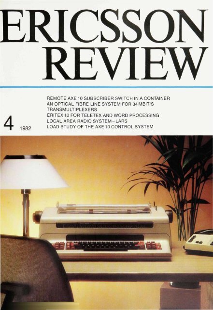
;2Remote AXE <strong>10</strong> Subscriber Switch<strong>in</strong> a Conta<strong>in</strong>erBjorn NorevikThe digital <strong>subscriber</strong> <strong>switch</strong> <strong>in</strong> the AXE <strong>10</strong> system c<strong>an</strong> be placed either <strong>in</strong> theparent exch<strong>an</strong>ge or <strong>remote</strong>ly. In the case of <strong>remote</strong> <strong>subscriber</strong> <strong>switch</strong>es it c<strong>an</strong>often be <strong>an</strong> adv<strong>an</strong>tage to have the equipment <strong>in</strong>stalled <strong>in</strong> a conta<strong>in</strong>er, not only asa temporary solution but also as a more perm<strong>an</strong>ent arr<strong>an</strong>gement. A productpackage has therefore been prepared which c<strong>an</strong> be used for <strong>remote</strong> units ofdifferent sizes up to 2048 <strong>subscriber</strong>s. The product package also <strong>in</strong>cludescool<strong>in</strong>g equipment, which c<strong>an</strong> be of the conventional type or a system wherewater is used to remove the surplus heat. The latter system offers st<strong>an</strong>dbycool<strong>in</strong>g if there is a ma<strong>in</strong>s failure.The author discusses the motives for this type of equipment <strong>an</strong>d what dem<strong>an</strong>dsc<strong>an</strong> be made on it, <strong>an</strong>d also describes the equipment <strong>in</strong>cluded <strong>in</strong> the productpackage.UDC 621 395 3When pl<strong>an</strong>n<strong>in</strong>g a new telephone networkor extend<strong>in</strong>g <strong>an</strong> exist<strong>in</strong>g one it isnecessary to assess m<strong>an</strong>y uncerta<strong>in</strong> factors.However, some basic facts are wellknown. The <strong>subscriber</strong> network is responsiblefor the greater part of theoverall cost of the telephone network.Thus <strong>an</strong> extension often requires large<strong>in</strong>vestments <strong>in</strong> the network, particularlyif exist<strong>in</strong>g cable routes are already fullyutilized.Consideration must also be paid to <strong>in</strong>creases<strong>in</strong> the build<strong>in</strong>g costs. Uncerta<strong>in</strong>factors, e.g. the rate of growth <strong>an</strong>d thedem<strong>an</strong>d for new telephone facilities,necessitate flexibility <strong>in</strong> the choice ofboth temporary <strong>an</strong>d perm<strong>an</strong>ent solutions.A digital <strong>remote</strong> <strong>subscriber</strong><strong>switch</strong>-<strong>an</strong> economicsolutionThe digital <strong>subscriber</strong> <strong>switch</strong> <strong>in</strong> AXE <strong>10</strong>has been described <strong>in</strong> detail <strong>in</strong> a previousarticle 1 . The article also describedhow the digital <strong>subscriber</strong> <strong>switch</strong> couldbe <strong>in</strong>stalled <strong>remote</strong>ly from the parent exch<strong>an</strong>ge.A <strong>remote</strong> digital <strong>subscriber</strong> <strong>switch</strong>, RSS,constitutes <strong>an</strong> <strong>in</strong>tegral part of <strong>an</strong> AXE <strong>10</strong>exch<strong>an</strong>ge, <strong>an</strong>d <strong>subscriber</strong>s connectedto RSS are thus offered exactly the samefacilities as other AXE <strong>10</strong> <strong>subscriber</strong>s.It is economical to connect <strong>remote</strong> <strong>subscriber</strong><strong>switch</strong>es to their parent exch<strong>an</strong>gesby me<strong>an</strong>s of PCM l<strong>in</strong>ks bothwhen build<strong>in</strong>g up new <strong>subscriber</strong> networks<strong>an</strong>d when extend<strong>in</strong>g exist<strong>in</strong>gones. In the case of new networks theFig. 1A conta<strong>in</strong>er <strong>in</strong> place <strong>an</strong>d connected to the network<strong>in</strong> Saudi-Arabia
175BJORN NOREVIKPublic Telecommunications DivisionTeletonaktiebolaget LM Ericssonneed for cables <strong>in</strong> the primary networkwill be considerably less th<strong>an</strong> if the <strong>subscriber</strong>sare connected directly to theparent exch<strong>an</strong>ge, <strong>an</strong>d <strong>in</strong> the case of extensionslarge <strong>in</strong>vestments c<strong>an</strong> also beavoided. This applies especially if thecable routes are already fully utilized,s<strong>in</strong>ce every PCM l<strong>in</strong>k <strong>in</strong>stalled frees severalcable pairs.Remote <strong>subscriber</strong> <strong>switch</strong>es<strong>in</strong> conta<strong>in</strong>ersThe relatively limited physical size ofRSS also makes it possible to <strong>in</strong>stall it <strong>in</strong>a conta<strong>in</strong>er, fig. 1. This method c<strong>an</strong> beused for <strong>subscriber</strong> <strong>switch</strong>es with bothtemporary <strong>an</strong>d perm<strong>an</strong>ent positions.The equipment c<strong>an</strong> be moved accord<strong>in</strong>gto need.A conta<strong>in</strong>er is also considerably cheaperth<strong>an</strong> a conventional exch<strong>an</strong>ge build<strong>in</strong>g.ApplicationsThe reasons given above make RSS <strong>in</strong>stalled<strong>in</strong> a conta<strong>in</strong>er particularly suitablefor the follow<strong>in</strong>g applications.- as a perm<strong>an</strong>ent extension to <strong>an</strong> alreadyfully developed exch<strong>an</strong>gebuild<strong>in</strong>g- as a perm<strong>an</strong>ent extension <strong>in</strong> <strong>an</strong> exist<strong>in</strong>gnetwork, particularly when the exist<strong>in</strong>gcable routes are fully exploited- as a semi-perm<strong>an</strong>ent or perm<strong>an</strong>entsolution when build<strong>in</strong>g up a new <strong>subscriber</strong>network <strong>an</strong>d there is some uncerta<strong>in</strong>tyregard<strong>in</strong>g future developments- as a temporary solution when quickservice is required, i.e. before the exch<strong>an</strong>gebuild<strong>in</strong>g has been completedor <strong>in</strong> emergency situations when theord<strong>in</strong>ary exch<strong>an</strong>ge is out of operationbecause of a fire or for some otherreason.Product packageThe type of conta<strong>in</strong>er chosen for RSS is<strong>an</strong> <strong>in</strong>sulated refrigeration conta<strong>in</strong>er,built to ISO st<strong>an</strong>dard dimensions 2 (<strong>10</strong> or20 feet long, 9 feet high, 8 feet wide). Theshorter conta<strong>in</strong>er is used for <strong>an</strong> RSS forup to 512 <strong>subscriber</strong>s, <strong>an</strong>d the 20-footconta<strong>in</strong>er for the full 2048-group, fig. 2.S<strong>in</strong>ce the conta<strong>in</strong>er is <strong>in</strong>sulated, thesame type c<strong>an</strong> be used for all <strong>in</strong>stallationsregardless of the widely differ<strong>in</strong>genvironments that will be encounteredaround the world, <strong>an</strong>d adaptations tosuit different markets are avoided. Anefficient <strong>an</strong>d reliable cool<strong>in</strong>g systemensures a suitable work<strong>in</strong>g environmentfor the telephone equipment <strong>in</strong>side theconta<strong>in</strong>er.The conta<strong>in</strong>er is built to ISO st<strong>an</strong>dard 2as regards dimensions <strong>an</strong>d h<strong>an</strong>dl<strong>in</strong>g facilities.The h<strong>an</strong>dl<strong>in</strong>g requirements relateto, for example its strength <strong>an</strong>d devicesfor lift<strong>in</strong>g the conta<strong>in</strong>er. The st<strong>an</strong>darddimensions also facilitate tr<strong>an</strong>sport(by tra<strong>in</strong>, lorry, boat or aricraft),s<strong>in</strong>ce st<strong>an</strong>dardized h<strong>an</strong>dl<strong>in</strong>g equipment,such as cr<strong>an</strong>es <strong>an</strong>d trucks, c<strong>an</strong> beused. The easy h<strong>an</strong>dl<strong>in</strong>g <strong>an</strong>d the st<strong>an</strong>dardizedconstruction also contributeto speedy <strong>in</strong>stallation on site, so that theequipment c<strong>an</strong> be put <strong>in</strong>to operation almostimmediately. If necessary, RSSc<strong>an</strong> also just as easily be moved to a newsite later on, to meet new dem<strong>an</strong>ds.S<strong>in</strong>ce the version of RSS <strong>in</strong>tended forconta<strong>in</strong>er <strong>in</strong>stallation is st<strong>an</strong>dardized,all cabl<strong>in</strong>g with<strong>in</strong> <strong>an</strong>d between magaz<strong>in</strong>egroups, as well as to the otherFig. 2The layout of a 20-foot conta<strong>in</strong>er with a <strong>remote</strong>digital AXE <strong>10</strong> <strong>subscriber</strong> <strong>switch</strong> for 2048 <strong>subscriber</strong>sLSM L<strong>in</strong>e <strong>switch</strong><strong>in</strong>g modulesLT L<strong>in</strong>e term<strong>in</strong>al for PCMR Power supply equipmentSTB Signall<strong>in</strong>g term<strong>in</strong>al equipmentSE Special <strong>subscriber</strong> equipment tor co<strong>in</strong> box sets,<strong>subscriber</strong>s' private meters etc.MDF Ma<strong>in</strong> distribution trameAC Alternat<strong>in</strong>g current connector
Fig. 3The conta<strong>in</strong>er is brought out from one ot Ericsson'sfactories near Stockholm, SwedenFig. 4The conta<strong>in</strong>er en routeFig. 5Tr<strong>an</strong>sshipmentFig. 6Jacks are used at the <strong>in</strong>stallation site to lower theconta<strong>in</strong>er onto its baseequipment <strong>in</strong> the conta<strong>in</strong>er, c<strong>an</strong> be prefabricated<strong>an</strong>d <strong>in</strong>stalled before delivery.This me<strong>an</strong>s a considerable reduction <strong>in</strong>the amount of <strong>in</strong>stallation work requiredon site.A complete RSS <strong>in</strong> a conta<strong>in</strong>er, i.e. theproduct package, <strong>in</strong>cludes power feed<strong>in</strong>g,cool<strong>in</strong>g, ma<strong>in</strong> distribution frameetc., <strong>an</strong>d the equipment <strong>in</strong> the conta<strong>in</strong>erc<strong>an</strong> therefore be tested as a completeunit before delivery. This me<strong>an</strong>s that the<strong>in</strong>stallation test<strong>in</strong>g on site is reduced toa simple verification test before theequipment is taken <strong>in</strong>to service.LayoutFig. 2 shows the layout of a conta<strong>in</strong>erwith a full 2048-group RSS. The necessarytelephone equipment, l<strong>in</strong>e modulesLSMO-15 for the 128-groups <strong>an</strong>d theequipment common for the whole 2048-group, are placed <strong>in</strong> a s<strong>in</strong>gle row aga<strong>in</strong>stthe wall <strong>an</strong>d one double row. This layoututilizes the available space efficiently<strong>an</strong>d gives two aisles with sufficientspace for <strong>in</strong>stallation <strong>an</strong>d ma<strong>in</strong>ten<strong>an</strong>cework. The cool<strong>in</strong>g equipment has beenplaced at one end so that <strong>in</strong>stallation aswell as <strong>an</strong>y ma<strong>in</strong>ten<strong>an</strong>ce c<strong>an</strong> be carriedout via the doors at that end, withoutaccess to the telephone equipment. Thisalso applies for the battery area, whichfor safety reasons is completely separate,with access via a separate door.The ma<strong>in</strong> distribution frame c<strong>an</strong> also beseparated from the telephone equipment,by me<strong>an</strong>s of a fold<strong>in</strong>g <strong>in</strong>ner door,thereby creat<strong>in</strong>g a dust lock. The ma<strong>in</strong>distribution frame is also placed aga<strong>in</strong>stthe wall <strong>in</strong> order to m<strong>in</strong>imize the amountof space required <strong>an</strong>d to ensure sufficientwork<strong>in</strong>g space for <strong>in</strong>stallation <strong>an</strong>d<strong>an</strong>y alterations that might be necessarydur<strong>in</strong>g operation. The conta<strong>in</strong>er alsohas a certa<strong>in</strong> amount of space for tr<strong>an</strong>smissionequipment, temporarily connectedI/O devices, fire ext<strong>in</strong>guishersetc.Conta<strong>in</strong>er constructionThe conta<strong>in</strong>er is made of a special steelwith the walls welded to a framework sothat <strong>an</strong> airtight <strong>an</strong>d robust constructionis obta<strong>in</strong>ed. It is then given a f<strong>in</strong>ish thatprovides long-term protection aga<strong>in</strong>stcorrosion even <strong>in</strong> extreme environments.Ventilation <strong>an</strong>d dehumidificationtakes place via <strong>an</strong> air <strong>in</strong>let at one end <strong>an</strong>dthrough <strong>an</strong> outlet at the other end viathebattery area.The conta<strong>in</strong>er is equipped with four adjustablefeet so that it c<strong>an</strong> be alignedhorizontally on a concrete foundation orconcrete pl<strong>in</strong>ths, fig. 1.Cool<strong>in</strong>g systemIn order to ensure a suitable environmentfor the telephone equipment, regardlessof the external environment,RSS <strong>in</strong> a conta<strong>in</strong>er c<strong>an</strong> be equipped witha conventional air-condition<strong>in</strong>g systemor Ericsson's new cool<strong>in</strong>g system whichuses water to remove the surplus heat.This system has been described <strong>in</strong> detail<strong>in</strong> a previous issue of Ericsson Review 3 .Ericsson's new cool<strong>in</strong>g system is particularlysuitable for unm<strong>an</strong>ned equipmentof this type, s<strong>in</strong>ce it has high reliability<strong>an</strong>d requires only a m<strong>in</strong>imum ofma<strong>in</strong>ten<strong>an</strong>ce <strong>an</strong>d, above all, s<strong>in</strong>ce it isequipped with st<strong>an</strong>dby cool<strong>in</strong>g <strong>in</strong> theform of a t<strong>an</strong>k of cold water. This t<strong>an</strong>k isdimensioned so that if a ma<strong>in</strong>s failureshould occur the st<strong>an</strong>dby t<strong>an</strong>k will lastas long as the batteries of the powerequipment. This ensures reliable operationthroughout the specified st<strong>an</strong>dbytime.Power equipmentThe power equipment is of the typeBZA<strong>10</strong>6, a type which has been developedfor use <strong>in</strong> small equipments likeRSS <strong>an</strong>d which meets Ericsson's st<strong>an</strong>dardrequirements for power distributionto electronic exch<strong>an</strong>ge systems.The power equipment has a modularstructure <strong>an</strong>d its capacity c<strong>an</strong> be adaptedfor RSS units of different size.The batteries are placed <strong>in</strong> a separatebattery area, mounted on one to threeshelves. There is sufficient space for thelarge battery capacity required <strong>in</strong> orderto provide the long st<strong>an</strong>dby time, which<strong>in</strong> m<strong>an</strong>y situations is needed for a <strong>remote</strong><strong>subscriber</strong> <strong>switch</strong> <strong>in</strong> a conta<strong>in</strong>er.Ma<strong>in</strong> distribution frameThe ma<strong>in</strong> distribution frame is of thesame type as Ericsson's m<strong>in</strong>iature MDF.BAB 340 with slot connectors, but withthe construction practice modified fors<strong>in</strong>gle-sided <strong>in</strong>stallation (BAB345).fig. 7. This layout provides ample work<strong>in</strong>gspace for <strong>in</strong>stallation <strong>an</strong>d for alterationsriur<strong>in</strong>n nnerat<strong>in</strong>n
177Fig. 7Interior view ot a conta<strong>in</strong>er with equipment for2048 <strong>subscriber</strong>s. The ma<strong>in</strong> distribution framec<strong>an</strong> be seen <strong>in</strong> the foregroundSummaryThe adv<strong>an</strong>tages of plac<strong>in</strong>g the AXE <strong>10</strong><strong>remote</strong> digital <strong>subscriber</strong> <strong>switch</strong> <strong>in</strong> aconta<strong>in</strong>er c<strong>an</strong> be summarized as follows:- In all applications there is a considerablereduction of the <strong>in</strong>stallationtime, s<strong>in</strong>cetheequipment c<strong>an</strong> be testedas a complete unit at the factorybefore delivery.- The chosen conta<strong>in</strong>er types are builtto ISO st<strong>an</strong>dard sizes, which simplifiesh<strong>an</strong>dl<strong>in</strong>g <strong>an</strong>d tr<strong>an</strong>sport,figs.3-6.- The exch<strong>an</strong>ge environment for thetelephone equipment is ma<strong>in</strong>ta<strong>in</strong>edwith the aid of a conventional air-condition<strong>in</strong>gsystem or Ericsson's newcool<strong>in</strong>g system with st<strong>an</strong>by cool<strong>in</strong>gdur<strong>in</strong>g ma<strong>in</strong>s failures.- The power distribution meets Ericsson'sst<strong>an</strong>dard requirements for electronicexch<strong>an</strong>ges.- The batteries are accessible from outsidethrough a separate door, <strong>an</strong>d thema<strong>in</strong> distribution frame c<strong>an</strong> also beseparated from the telephone equipment.- Two sizes of RSS <strong>in</strong> conta<strong>in</strong>er areavailable:• up to 512 <strong>subscriber</strong>s <strong>in</strong> a <strong>10</strong>-footconta<strong>in</strong>er• up to 2048 <strong>subscriber</strong>s <strong>in</strong> a 20-footconta<strong>in</strong>erOther AXE <strong>10</strong> applicationsThe digital <strong>remote</strong> <strong>subscriber</strong> <strong>switch</strong> isalso available <strong>in</strong> a smaller size for ther<strong>an</strong>ge 64-128 <strong>subscriber</strong>s. This equipmentmakes it possible to <strong>in</strong>troduceAXE <strong>10</strong> with its m<strong>an</strong>y facilities <strong>in</strong> the outermostparts of the <strong>subscriber</strong> network.The volume of this equipment is so smallthat it has been mounted <strong>in</strong> a cab<strong>in</strong>et for<strong>in</strong>stallation either <strong>in</strong>doors or outdoors.Other AXE <strong>10</strong> products, ma<strong>in</strong>ly small exch<strong>an</strong>ges,are also available <strong>in</strong> st<strong>an</strong>dardizedconta<strong>in</strong>er versions. They have thesame general structure as described forRSS <strong>in</strong> this article, <strong>an</strong>d thus also thesame specific properties <strong>an</strong>d adv<strong>an</strong>tages.References1. Persson, K. <strong>an</strong>d Sundstrom, S.: DigitalLocal Exch<strong>an</strong>ges AXE <strong>10</strong>. EricssonRev. 58(1981):3, pp. <strong>10</strong>2-1<strong>10</strong>.2. ISO St<strong>an</strong>dard TC<strong>10</strong>4. Freight Conta<strong>in</strong>ers.3. Almquist, R.: A Cool<strong>in</strong>g System forElectronic Telephone Exch<strong>an</strong>ges.Ericsson Rev. 58 (1981):4. pp. 188-195.
An Optical Fibre L<strong>in</strong>e Systemfor 34 Mbit/sTommy J<strong>an</strong>sson <strong>an</strong>d Bo StjernlofThis article <strong>in</strong>troduces Ericsson s digital l<strong>in</strong>e system for <strong>optical</strong> <strong>fibre</strong> cable.ZAM34-2. The tr<strong>an</strong>smission rate of the system is 34 Mbit s. which corresponds to480 PCM coded telephone ch<strong>an</strong>nels. The system meets all relev<strong>an</strong>t CCITT <strong>an</strong>dCEPT recommendations. It is primarily <strong>in</strong>tended for use <strong>in</strong> urb<strong>an</strong> networks, e.g.as the tr<strong>an</strong>smission l<strong>in</strong>k between exch<strong>an</strong>ges or between <strong>an</strong> exch<strong>an</strong>ge <strong>an</strong>d <strong>an</strong>umber of <strong>remote</strong> concentrators or as <strong>an</strong> entr<strong>an</strong>ce l<strong>in</strong>k to a radio relay l<strong>in</strong>k. Thesystem is available <strong>in</strong> two versions, one with a laser tr<strong>an</strong>smitter <strong>an</strong>d the otherwith a light emitt<strong>in</strong>g diode (LED) tr<strong>an</strong>smitter. The laser permits a repeaterspac<strong>in</strong>g of 12km as aga<strong>in</strong>st 5 km for the LED. However, the LED version offersgreater reliability.<strong>fibre</strong>s hav<strong>in</strong>g <strong>an</strong> attenuation of 3-4dBper km <strong>an</strong>d a b<strong>an</strong>dwidth of 300 MHz • kmat a wavelength of 850 nm.The small spectral width of the laser,together with the large b<strong>an</strong>dwidth of thegraded <strong>in</strong>dex <strong>fibre</strong>, result <strong>in</strong> negligiblematerial <strong>an</strong>d mode dispersions <strong>in</strong> thelaser system, e.g. the system is limitedby the attenuation. Because of the relativelylarge spectral width of the LED,the limitations of this system, is set bythe material dispersion of the <strong>fibre</strong>.UDC 621.315:535 394621.391.63Fig. 1The equipment <strong>in</strong> the 34 Mbit/s systemLDM L<strong>in</strong>e term<strong>in</strong>at<strong>in</strong>g magaz<strong>in</strong>eFDU Fault detector unitFDS Fault detection shelfSCS Service circuit shelfST Service telephoneCTB Cable term<strong>in</strong>at<strong>in</strong>g boxD3 34 Mbit/s <strong>in</strong>terface, CCITT G.703 8F3 41 MBaud <strong>optical</strong> <strong>fibre</strong> <strong>in</strong>terfaceAL Alarm <strong>in</strong>terfaceDur<strong>in</strong>g the years 1977-1979 a 34 Mbit/sl<strong>in</strong>e system for <strong>optical</strong> <strong>fibre</strong>, ZAM34-1,was developed for field trials. The purposeof this system was to give Ericsson<strong>an</strong>d the telephone adm<strong>in</strong>istrations theopportunity to ga<strong>in</strong> experience of digitall<strong>in</strong>e systems for <strong>optical</strong> <strong>fibre</strong> cable. Anumber of such systems have been deliveredto various users, <strong>an</strong>d today severalare <strong>in</strong> regular operation. The newl<strong>in</strong>e system, ZAM34-2, is to a great extentbased on the experience ga<strong>in</strong>eddur<strong>in</strong>g the design <strong>an</strong>d <strong>in</strong>stallation ofZAM34-1 field trial systems 45 .L<strong>in</strong>e system ZAM34-2 with a tr<strong>an</strong>smissionrate of 34.368 Mbit/s is <strong>in</strong>tended fordigital tr<strong>an</strong>smission of 480 PCM codedtelephone ch<strong>an</strong>nels over <strong>fibre</strong> cable.The light source used is either a laserdiode or a light emitt<strong>in</strong>g diode (LED),<strong>an</strong>d the photo detector is <strong>an</strong> aval<strong>an</strong>chephoto diode (APD). The tr<strong>an</strong>smissionmedium is a cable with graded <strong>in</strong>dexZAM34-2 offers the follow<strong>in</strong>g adv<strong>an</strong>tages:- laser or LED tr<strong>an</strong>smitter. The latter,which could be used for repeaterspac<strong>in</strong>gs less th<strong>an</strong> 5 km, offers higherreliability <strong>an</strong>d lower costs- large repeater spac<strong>in</strong>gs, 12 km withlaser tr<strong>an</strong>smitters- thermoelectrical cool<strong>in</strong>g of the laserdiode for maximum reliability- modular structure. The system c<strong>an</strong>easily be converted from a shortwavesystem for 850 nm to a longwave systemfor 1300 nm by ch<strong>an</strong>g<strong>in</strong>g thetr<strong>an</strong>smitter <strong>an</strong>d receiver units- simple connection to the <strong>fibre</strong> viaplug-<strong>in</strong> <strong>optical</strong> connectors which donot require <strong>an</strong>y subsequent adjustment- flexible mech<strong>an</strong>ical constructionus<strong>in</strong>g Ericsson's BYB constructionpractice, which simplifies <strong>in</strong>stallation<strong>an</strong>d h<strong>an</strong>dl<strong>in</strong>g. All connections aremade with connectors on the fronts ofthe units
TOMMY JANSSONBO STJERNLOFFibre optics <strong>an</strong>dl<strong>in</strong>e tr<strong>an</strong>smissionTelefonaktiebolaget LM Ericsson- the same magaz<strong>in</strong>e is used for the l<strong>in</strong>eterm<strong>in</strong>al <strong>an</strong>d the <strong>in</strong>termediate repeater,which makes it easy to ch<strong>an</strong>ge theequipment over from term<strong>in</strong>ation tothrough-connection- fault location function <strong>an</strong>d facilitiesfor connection to Tr<strong>an</strong>smission Ma<strong>in</strong>ten<strong>an</strong>ceSystem ZAN <strong>10</strong>1System characteristicsThe <strong>in</strong>terface for the 34 Mbit/s l<strong>in</strong>e systemis D3. <strong>an</strong>d is <strong>in</strong> accord<strong>an</strong>ce withCCITT Rec. G.703. An 8/34 Mbit/s or2/34 Mbit/s multiplexer, e.g. Ericsson'sZAK 120/480' orZAK30/480'.oradigitalradio relay l<strong>in</strong>k c<strong>an</strong> be connected to this<strong>in</strong>terface.- fault detection equipment for <strong>remote</strong>supervision of l<strong>in</strong>e term<strong>in</strong>als <strong>an</strong>d <strong>in</strong>termediaterepeaters- two or four-wire service circuit equipment<strong>in</strong> the term<strong>in</strong>al bay, <strong>an</strong>d connectionpo<strong>in</strong>ts <strong>in</strong> the <strong>in</strong>termediate repeatersfor a service telephoneThe <strong>in</strong>com<strong>in</strong>g l<strong>in</strong>e cable isterm<strong>in</strong>ated <strong>in</strong>a cable term<strong>in</strong>at<strong>in</strong>g box, where the<strong>fibre</strong>s are distributed to the different systems.In the box the <strong>fibre</strong>s of the l<strong>in</strong>ecable are welded to the <strong>fibre</strong>s <strong>in</strong> the baycables. The other ends of the bay cablesare fitted with plug-<strong>in</strong> <strong>optical</strong> connectors,for connection to the tr<strong>an</strong>smitter<strong>an</strong>d receiver units of the system <strong>in</strong>question.Fig. 2Block diagram of the l<strong>in</strong>e term<strong>in</strong>at<strong>in</strong>g magaz<strong>in</strong>eAISDCLCELCEILSRLSTLDDPFLD3Alarm <strong>in</strong>dication signalData ch<strong>an</strong>nelL<strong>in</strong>e code error detectionL<strong>in</strong>e code error <strong>in</strong>jectionLoss of signal, receive directionLoss of signal, tr<strong>an</strong>smit directionLaser diode degradationFailure of local power supplyL<strong>in</strong>e system ZAM34-2, fig. 1, comprisesl<strong>in</strong>e term<strong>in</strong>als <strong>an</strong>d two-way <strong>in</strong>termediaterepeaters for tr<strong>an</strong>smission over <strong>optical</strong><strong>fibre</strong> cableThe equipment is normally mounted <strong>in</strong>M5/BYB bays <strong>an</strong>d consists of- l<strong>in</strong>e term<strong>in</strong>at<strong>in</strong>g magaz<strong>in</strong>es, LTM,where the signal is recoded, the jitteris reduced <strong>an</strong>d the l<strong>in</strong>e is supervised- locally powered two-way <strong>in</strong>termediaterepeaters that regenerate the signalat regular <strong>in</strong>tervals along the <strong>fibre</strong>cable- a cable term<strong>in</strong>at<strong>in</strong>g box (CTB) forconnect<strong>in</strong>g the <strong>fibre</strong>s <strong>in</strong> the l<strong>in</strong>e cableto the <strong>fibre</strong>s <strong>in</strong> the bay cablesAny copper pairs <strong>in</strong> the <strong>fibre</strong> cable c<strong>an</strong>also be term<strong>in</strong>ated <strong>in</strong> the cable term<strong>in</strong>at<strong>in</strong>gbox.The equipment is easy to <strong>in</strong>stall <strong>an</strong>d haswell def<strong>in</strong>ed <strong>in</strong>ternal <strong>in</strong>terfaces TheBYB magaz<strong>in</strong>es are delivered with theunits <strong>in</strong> place <strong>an</strong>d with all external connectionson the front of the units. Theequipment is strapped for the most commonapplication, <strong>an</strong>d only a m<strong>in</strong>imumnumber of straps have to be made dur<strong>in</strong>g<strong>in</strong>stallation.Term<strong>in</strong>al equipmentL<strong>in</strong>e term<strong>in</strong>at<strong>in</strong>g magaz<strong>in</strong>eThe ma<strong>in</strong> functions of the l<strong>in</strong>e term<strong>in</strong>at<strong>in</strong>gmagaz<strong>in</strong>e, LTM, fig. 2, are to- adapt the signal <strong>in</strong> the send <strong>an</strong>d receivedirections between the D3 <strong>in</strong>terfacest<strong>an</strong>dardized by CCITT for34 Mbit/s <strong>an</strong>d the <strong>optical</strong> <strong>fibre</strong> <strong>in</strong>terfaceF3- detect <strong>an</strong>d <strong>in</strong>dicate alarms.The basic version of the l<strong>in</strong>e term<strong>in</strong>alconsists of seven pr<strong>in</strong>ted board assemblies:- <strong>in</strong>terface unit- l<strong>in</strong>e coder- laser or LED tr<strong>an</strong>smitter- APD receiver- l<strong>in</strong>e decoder- alarm unit- d.c./d.c. converterfor±5V<strong>an</strong>d ±12V.In the receive direction of the <strong>in</strong>terfaceunit the HDB3 signal from the D3 <strong>in</strong>terfaceis equalized for the attenuation ofthe connect<strong>in</strong>g cable (max. 12dB at
Fig. 3Repeater spac<strong>in</strong>gs <strong>an</strong>d hardware complexity withdifferent types of codes. The choice of the 5B6Bcode gives a good compromise between hardwarecomplexity <strong>an</strong>d dispersion limit<strong>in</strong>g17 MHz) <strong>an</strong>d regenerated. The signal isthen recoded to a b<strong>in</strong>ary serial bitstream <strong>an</strong>d passed to the l<strong>in</strong>e coder Inthe case of loss of <strong>in</strong>put signal <strong>an</strong> alarmis given to the alarm unit. Violations ofthe HDB3 cod<strong>in</strong>g law result <strong>in</strong> <strong>an</strong> errorpulse which is available at a test po<strong>in</strong>tThe l<strong>in</strong>e coder carries out the code conversionto adapt the data bit stream for alaser or LED tr<strong>an</strong>smitter. The chosencode is of type 5B6B, i.e. five b<strong>in</strong>ary symbolsare recoded as six b<strong>in</strong>ary symbols.This gives a symbol rate on the <strong>fibre</strong>cable of 6 345 = 41 MBaud S<strong>in</strong>ce thenumber of <strong>in</strong>com<strong>in</strong>g b<strong>in</strong>ary states.2 5 = 32, is less th<strong>an</strong> the number of outgo<strong>in</strong>gb<strong>in</strong>ary states. 2 6 = 64, the codehas built-<strong>in</strong> redund<strong>an</strong>cy This redund<strong>an</strong>cyis used to create a code spectrumwith a const<strong>an</strong>t d.c voltage component<strong>an</strong>d a spectral energy distribution that issuited for <strong>optical</strong> tr<strong>an</strong>smission. The redund<strong>an</strong>cyis also used for error supervisionof the signal <strong>an</strong>d to get alow-capacityasynchronous data ch<strong>an</strong>nelThe choice of code is by necessity acompromise. Other codes, i.e. 3B4Bwhich is used <strong>in</strong> ZAM 34-1. give a greaterdispersion penalty <strong>in</strong> LED systems.Higher order codes would require toocomplex equipment, fig.3.The bit rate conversion that is neededfor the cod<strong>in</strong>g is carried out with the aidof a crystal-controlled phase lockedloop, PLL. The loop b<strong>an</strong>dwidth has beenchosen so that the jitter on the <strong>in</strong>com<strong>in</strong>gsignal is reduced, result<strong>in</strong>g <strong>in</strong> a decreasedalignment jitter requirement <strong>in</strong>the receivers of the repeater.L<strong>in</strong>e code errors c<strong>an</strong> be <strong>in</strong>jected <strong>in</strong> thel<strong>in</strong>e coder at <strong>an</strong> optional rate <strong>in</strong> order totest the fault location system <strong>an</strong>d alarmunit. The cod<strong>in</strong>g ensures that none ofthese bit errors rema<strong>in</strong> after the decod<strong>in</strong>gof the l<strong>in</strong>e signal.The laser tr<strong>an</strong>smitter receives the coded41 MBaud NRZ (Non Return to Zero) bitstream <strong>an</strong>d the clock signal from the l<strong>in</strong>ecoder <strong>an</strong>d converts them to a 41 MBaudRZ (Return to Zero) bit stream This isdone <strong>in</strong> order to reduce the problems of<strong>in</strong>ter-symbol <strong>in</strong>terference <strong>in</strong> the receiver.The RZ signal modulates a laserwhich provides <strong>an</strong> <strong>optical</strong> signal on the<strong>fibre</strong> cable The operat<strong>in</strong>g po<strong>in</strong>t of thelaser is me<strong>an</strong> value regulated by me<strong>an</strong>sof <strong>optical</strong> feedback with a photo diode atthe rear mirror of the laser. This stabilizesthe laser operation <strong>an</strong>d compensatesfor temperature variations <strong>an</strong>dage<strong>in</strong>g effects.The laser is cooled by a thermoelectricelement to a const<strong>an</strong>t temperature <strong>in</strong>order to obta<strong>in</strong> maximum reliability. Aspecial laser unit has been developedwhich meets the system requirements.fig. 4.The laser temperature c<strong>an</strong> be checkedby measur<strong>in</strong>g a voltage <strong>in</strong> a test po<strong>in</strong>t onthe front of the unit.The operat<strong>in</strong>g life of the laser systemdepends ma<strong>in</strong>ly on the life of the laser,<strong>an</strong>d the system is therefore equippedwith a circuit which supervises the conditionof the laser. An alarm is givenwhen the laser has degraded. The alarmis given well <strong>in</strong> adv<strong>an</strong>ce, before the systemperform<strong>an</strong>ce is affected.Fig. 4The laser tr<strong>an</strong>smitter with the laser unit.The laser is cooled to a const<strong>an</strong>t temperature <strong>in</strong>order to obta<strong>in</strong> the highest possible reliability.The laser is stabilized by me<strong>an</strong>s of me<strong>an</strong> valueregulation of the operat<strong>in</strong>g po<strong>in</strong>tAn alternative to the laser tr<strong>an</strong>smitterhas been developed, namely <strong>an</strong> LEDtr<strong>an</strong>smitter which is <strong>in</strong>tended for shorttr<strong>an</strong>smission dist<strong>an</strong>ces. It is fully compatiblewith the laser tr<strong>an</strong>smitter as regardsits connection. The LED tr<strong>an</strong>smittergives the system even higher reliabilityth<strong>an</strong> the laser tr<strong>an</strong>smitter. Likethe latter, the LED tr<strong>an</strong>smitter convertsthe <strong>in</strong>com<strong>in</strong>g 41 MBaud NRZ flow to <strong>an</strong>outgo<strong>in</strong>g <strong>optical</strong> 41 MBaud RZ flow. TheLED is mounted on a cool<strong>in</strong>g fl<strong>an</strong>ge <strong>in</strong>order to reduce its operat<strong>in</strong>g temperature.The receiver detects the <strong>in</strong>com<strong>in</strong>g <strong>optical</strong>si<strong>an</strong>al <strong>an</strong>d converts it tn a 41 MRaurl
181Fig. 6Oscilloscope picture of the signal at the detectionpo<strong>in</strong>t <strong>in</strong> the form of <strong>an</strong> eye diagram tor a lasersystem. Cable length: <strong>10</strong>kmFig. 5aAPD receiver.The phase-locked loop is built up around avoltage controlled crystal oscillator, which ensureslow output jitterNRZ electrical bit stream. An aval<strong>an</strong>chephoto diode, APD, is used as the photodetector <strong>in</strong> order to obta<strong>in</strong> the best possiblereceiver sensitivity <strong>an</strong>d dynamicr<strong>an</strong>ge. After the conversion <strong>in</strong> the APDthe signal is amplified <strong>in</strong> <strong>an</strong> <strong>in</strong>put stage.This is followed by <strong>an</strong> amplifier with automaticga<strong>in</strong> control, AGC. The APD ismounted direct on the hybrid-type <strong>in</strong>putcircuit, fig.5. This m<strong>in</strong>imizes the <strong>in</strong>putcapacit<strong>an</strong>ce, which would otherwise reducethe sensitivity of the <strong>in</strong>put stageThe use of hybrid technology also m<strong>in</strong>imizesthe effects of <strong>an</strong>y electromagneticdisturb<strong>an</strong>ces. The sensitivity <strong>an</strong>d dynamicr<strong>an</strong>ge are further improved byregulation of the APD reverse voltage.When <strong>an</strong> LED tr<strong>an</strong>smitter is used, a dispersionequalizer is automatically connected<strong>in</strong> after the AGC amplifier Theamplified signal is filtered <strong>in</strong> a low-passfilter so that the highest possible signalto-noiseratio is obta<strong>in</strong>ed at the detectionpo<strong>in</strong>t. Fig. 6 shows the signal at thedetection po<strong>in</strong>t <strong>in</strong> the form of <strong>an</strong> eyediagram for a laser system with <strong>10</strong> km of<strong>fibre</strong> cable.The tim<strong>in</strong>g recovery from the signal flowtakes place <strong>in</strong> a PLL conta<strong>in</strong><strong>in</strong>g a voltagecontrolled crystal oscillator, whichprovides the necessary compensationfor temperature variations <strong>an</strong>d age<strong>in</strong>geffects. The relatively high Q value of theoscillator <strong>an</strong>d its <strong>in</strong>sensitivity to disturb<strong>an</strong>cesensure low output jitter. The signalis regenerated with the aid of therecovered tim<strong>in</strong>g. The b<strong>in</strong>ary regenerated41 MBaud signal <strong>an</strong>d the clock signalare fed to the decoder. These signalsare also accessible for <strong>an</strong> optional errordetector, ED The voltage across theAPD c<strong>an</strong> be measured at a test po<strong>in</strong>t onthe front of the unit. For reasons of safetythe voltage is divided down to a hundredthof the actual valueThe b<strong>in</strong>ary <strong>in</strong>put bit stream to the decoderis series/parallel converted <strong>an</strong>dcode converted <strong>in</strong> a 5B6B decoder. Thedata signal <strong>an</strong>d tim<strong>in</strong>g signal are thenfed to the previously described <strong>in</strong>terfaceunit.The redund<strong>an</strong>t words that are not used<strong>in</strong> the normal encod<strong>in</strong>g process causeerror pulses These pulses are fed to aresynchronization circuit <strong>an</strong>d also to <strong>an</strong>alarm unit. The resynchronization logicensures that the system is resynchronizedif the error rate of the <strong>in</strong>com<strong>in</strong>g bitstream is too high. The logic is fittedwith error burst block<strong>in</strong>g <strong>in</strong> order to preventresynchronization for high errorrates of very short duration. The <strong>in</strong>formationtr<strong>an</strong>smitted over the data ch<strong>an</strong>nelis also accessible <strong>in</strong> the decoderThe tim<strong>in</strong>g conversion required for thecode conversion is carried out with theaid of a crystal-controlled PLL. The loopb<strong>an</strong>dwidth has been chosen so that thel<strong>in</strong>e signal jitter is reduced The jitter outtowards the multiplex equipment isthereby m<strong>in</strong>imized. The serial datastream from the l<strong>in</strong>e decoder is HDB3coded <strong>in</strong> the send side of the <strong>in</strong>terfaceunit.Fig. 5bA part of the APD receiver with the lid removedfrom the unit conta<strong>in</strong><strong>in</strong>g the hybrid circuit withthe aval<strong>an</strong>che photo diode. The APD is mounteddirect on a hybrid circuit <strong>in</strong> order to ensure thebest possible receiver sensitivity. A wide dynamicr<strong>an</strong>ge is obta<strong>in</strong>ed through regulation of the APDvoltaae comb<strong>in</strong>ed with <strong>an</strong> AGC amplifier
182The primary alarms are those recommendedby CCITT. They are concentrated<strong>in</strong> the alarm unit of the magaz<strong>in</strong>e.Alarm concentration <strong>an</strong>d alarm tr<strong>an</strong>smissionare carried out <strong>in</strong> accord<strong>an</strong>cewith the same pr<strong>in</strong>ciples that apply forother equipment <strong>in</strong> the BYB constructionpractice. An alarm <strong>in</strong>dication signal(AIS) is <strong>in</strong>serted <strong>in</strong> the send or receivedirection if there is a loss of <strong>in</strong>put signalat the D3 <strong>in</strong>terface or too high error rateon the l<strong>in</strong>e.The equipment is mounted <strong>in</strong> a BYBmagaz<strong>in</strong>e, fig. 7, <strong>an</strong>d is powered from abattery via the d.C./d.c. converter <strong>in</strong> themagaz<strong>in</strong>e.It has been possible to use st<strong>an</strong>dard wirewrapp<strong>in</strong>g methods for the wir<strong>in</strong>g of theequipment, s<strong>in</strong>ce the <strong>in</strong>ternal tr<strong>an</strong>smissionsymbol rate between the pr<strong>in</strong>tedboard assemblies is limited to41 MBaud.Intermediate repeatersThe 34 Mbit/s l<strong>in</strong>e system is <strong>in</strong>tended primarilyfor urb<strong>an</strong> networks. This me<strong>an</strong>sthat the repeater spac<strong>in</strong>gs are such thatpo<strong>in</strong>t-to-po<strong>in</strong>t circuits or circuits conta<strong>in</strong><strong>in</strong>gonly a few <strong>in</strong>termediate repeatersare most likely to be used. In thosecases where <strong>in</strong>termediate repeatershave to be used it is therefore also possibleto use local power supply.The two-way <strong>in</strong>termediate repeater withlocal power supply is mounted <strong>in</strong> a BYBmagaz<strong>in</strong>e which is <strong>an</strong> equipment versionof the l<strong>in</strong>e term<strong>in</strong>at<strong>in</strong>g magaz<strong>in</strong>e.The <strong>in</strong>termediate repeater conists of- two laser tr<strong>an</strong>smitters- two APD receivers- one d.c./d.c. converter.Identical types of units are used <strong>in</strong> the<strong>in</strong>termediate repeater<strong>an</strong>d the l<strong>in</strong>e term<strong>in</strong>at<strong>in</strong>gmagaz<strong>in</strong>e.Intermediate repeaters which c<strong>an</strong> bepower fed via a separate copper pair <strong>in</strong>the <strong>fibre</strong> cable will be available later. Theonly modification required for these willbe to ch<strong>an</strong>ge the d.c./d.c. converters.These <strong>in</strong>termediate repeaters c<strong>an</strong> thenbe <strong>in</strong>stalled <strong>in</strong> buried conta<strong>in</strong>ers if required.Fig. 7The l<strong>in</strong>e term<strong>in</strong>at<strong>in</strong>g magaz<strong>in</strong>e is built up <strong>in</strong> a BYBmagaz<strong>in</strong>e, with the connectors at the front of theunits
183The l<strong>in</strong>e term<strong>in</strong>als <strong>an</strong>d <strong>in</strong>termediate repeatersc<strong>an</strong> be equipped with a unit forsupervis<strong>in</strong>g bit errors <strong>in</strong> the tr<strong>an</strong>smission.This error detector unit. ED, conta<strong>in</strong>stwo bit error detectors, one foreach direction of tr<strong>an</strong>smission, whichmonitor the variations <strong>in</strong> the runn<strong>in</strong>gdigital sum, <strong>an</strong>d which send error pulsesto the fault detector <strong>in</strong> the fault detectionsystem if bit errors are detected. EDalso conta<strong>in</strong>s a function for monitor<strong>in</strong>glaser alarms from the laser tr<strong>an</strong>smitters<strong>in</strong> the <strong>in</strong>termediate repeaters <strong>an</strong>d l<strong>in</strong>eterm<strong>in</strong>als. Any laser alarm causes shortcircuit<strong>in</strong>g of <strong>an</strong> extra copper pair, whichis connected to ED. The short circuit isdetected by the ED <strong>in</strong> the l<strong>in</strong>e term<strong>in</strong>al ofthe supervis<strong>in</strong>g station which is connectedto the term<strong>in</strong>al alarm unit viaconnectors on the fronts of both units.The extra copper pair is power fed fromthe supervis<strong>in</strong>g l<strong>in</strong>e term<strong>in</strong>al via a separate<strong>remote</strong> power feed<strong>in</strong>g unit.BayA bay holds term<strong>in</strong>al equipment for amaximum of ten systems. The capacityis reduced to six systems if a fault detectionshelf <strong>an</strong>d rectifier are also mounted<strong>in</strong> the bay. A board holder unit ismounted at the bottom of the bay. It c<strong>an</strong>conta<strong>in</strong> <strong>an</strong> alarm concentrator for bayalarms, a service telephone connector,<strong>an</strong>d also a d.c./d.c. converter for power<strong>in</strong>gthe fault detection shelf, if provided.Fault locationRepeater fault locationFaulty l<strong>in</strong>e repeaters are located with theaid of a fault detection system which iscommon for several l<strong>in</strong>e systems. Thesystem consists of a fault detection shelf(FDS), placed <strong>in</strong> the station from whichfault location is to be carried out, <strong>an</strong>d afault detector unit (FDU), placed togetherwith the <strong>in</strong>termediate repeaters.The fault detection shelf is identical tothe one used for Ericssons 2, 8 <strong>an</strong>d140Mbit/s l<strong>in</strong>e systems, which me<strong>an</strong>sthat it c<strong>an</strong> be connected to the Tr<strong>an</strong>smissionMa<strong>in</strong>ten<strong>an</strong>ce System ZAN <strong>10</strong>1The fault detection system makes it possibleto detect bit errors <strong>in</strong> the l<strong>in</strong>e signaldur<strong>in</strong>g traffic.Each repeater conta<strong>in</strong>s <strong>an</strong> ED, which isconnected to a common FDU. The latter,<strong>in</strong> its turn, is connected to the fault detectorshelf via a separate metallic wirepair.The fault detector unit is identical to thatused for the 140Mbit/s coaxial l<strong>in</strong>e systemZAY140-1 6 .Cable term<strong>in</strong>at<strong>in</strong>g boxL<strong>in</strong>e term<strong>in</strong>at<strong>in</strong>g magaz<strong>in</strong>eL<strong>in</strong>e term<strong>in</strong>at<strong>in</strong>g magaz<strong>in</strong>eInformation concern<strong>in</strong>g the bit errorrate on a certa<strong>in</strong> repeater output c<strong>an</strong> betr<strong>an</strong>smitted to the fault detection shelffor <strong>an</strong>alysis by me<strong>an</strong>s of a simple address<strong>in</strong>gprocedure. It is possible to locatea fault by address<strong>in</strong>g consecutive<strong>in</strong>termediate repeaters <strong>an</strong>d compar<strong>in</strong>gthe bit error rates The system c<strong>an</strong> betested by <strong>in</strong>ject<strong>in</strong>g code errors <strong>in</strong> the l<strong>in</strong>eterm<strong>in</strong>at<strong>in</strong>g magaz<strong>in</strong>e.Fig. 8A l<strong>in</strong>e term<strong>in</strong>al bay with six l<strong>in</strong>e term<strong>in</strong>als, cableterm<strong>in</strong>at<strong>in</strong>g box, fault detection shelf <strong>an</strong>d ma<strong>in</strong>srectifierFault detection shellL<strong>in</strong>e term<strong>in</strong>at<strong>in</strong>g magaz<strong>in</strong>ewith front coverRectifierService circuitA two-wire or four-wire service telephonecircuit is available <strong>in</strong> systemZAM34-2, for example at fault location.The fault detector units <strong>in</strong> repeater stationshave access to a service telephone.At the ends of the route the twoor four-wire service circuit equipment isconnected to the ord<strong>in</strong>ary two-wire servicetelephone <strong>in</strong> the M5/BYB bay.
184Technical dataDigital <strong>in</strong>terface (D3)Bit rateL<strong>in</strong>e codeImped<strong>an</strong>cePulse amplitudePermissible cableattenuation at 17 MHzOptical <strong>in</strong>terface (F3)Symbol rateL<strong>in</strong>e codeOutput powerWavelength (typical)Spectral b<strong>an</strong>dwidth (3 dB)Input sensitivityDynamic r<strong>an</strong>geTr<strong>an</strong>smission mediumFibre typePermissible dispersionCore diameterCladd<strong>in</strong>g diameterNumerical aperturePower supplyNom<strong>in</strong>al battery voltageMa<strong>in</strong>s voltageToler<strong>an</strong>ceMa<strong>in</strong>s frequencyPower consumptionL<strong>in</strong>e term<strong>in</strong>alIntermediate repeater(two-way)Fault locationLocat<strong>in</strong>g faulty repeatersMaximum number ofrepeater stationsService telephone circuitAmbient temperatureL<strong>in</strong>e term<strong>in</strong>alIntermediate repeaterDimensionsL<strong>in</strong>e term<strong>in</strong>al <strong>an</strong>d<strong>in</strong>termediate repeater34.368 Mbit/sHDB375 ohms, unbal<strong>an</strong>ced1 V12 dBLASER LED41.2416 MBaud5B6B-2 dBm -24 dBm830 nm 880 nmS3nm 5=50nm-51 dB -47 dB30 dBLow loss, graded<strong>in</strong>dex9 ns 18 ns50 |im125 |im0.21 ±0.0236, 48, 60 V1<strong>10</strong>, 127. 220 V<strong>10</strong>%45-65 Hz45 W16 WVia a metallic pair32Two-wire orfour-wire0 to +45"-20 to +55 : CH, W, D244x244x225 mmThe permissible attenuation over theloaded service circuit pair is 25dB fortwo-wire <strong>an</strong>d 40dB for four-wire circuits.In order to avoid extra copper pairs <strong>in</strong>the <strong>fibre</strong> cable, a new fault detection systemis be<strong>in</strong>g developed which utilizesthe possiblitity of tr<strong>an</strong>smitt<strong>in</strong>g the servicech<strong>an</strong>nel <strong>an</strong>d fault detection signalsover the <strong>fibre</strong> used for the normal tr<strong>an</strong>smission.SummaryL<strong>in</strong>e system ZAM 34-2 for <strong>optical</strong> <strong>fibre</strong> isa product with good technical perform<strong>an</strong>ce<strong>an</strong>d high reliability. It has a modularstructure, is robust <strong>an</strong>d easy to h<strong>an</strong>dle<strong>an</strong>d <strong>in</strong>stall, features which are all ofgreat import<strong>an</strong>ce to the user. Theseproperties have been achieved by- draw<strong>in</strong>g on the experience ga<strong>in</strong>edfrom the design <strong>an</strong>d <strong>in</strong>stallation ofother digital l<strong>in</strong>e systems, such asZAM 34-1 <strong>an</strong>d ZAY 140-1- apply<strong>in</strong>g st<strong>an</strong>dardized constructionpractice, alarm <strong>an</strong>d supervision methods- us<strong>in</strong>g plug-<strong>in</strong> <strong>optical</strong> <strong>fibre</strong> connectors- simulat<strong>in</strong>g <strong>an</strong>d optimiz<strong>in</strong>g the systemperform<strong>an</strong>ce <strong>an</strong>d the functions of thecircuits with the aid of computer programs- us<strong>in</strong>g active cool<strong>in</strong>g <strong>an</strong>d cont<strong>in</strong>uousalarm monitor<strong>in</strong>g of the laser- us<strong>in</strong>g LED for dist<strong>an</strong>ces of less th<strong>an</strong>5km.References1. Hamacher, H.-H. <strong>an</strong>d Karlsson. S :Higher-Order Digital multiplexers.Ericsson Rev. 58 (1981):4, pp. 196-200.2. Hallberg. P.-A <strong>an</strong>d Viklund, B :Construction Practice BYB forTr<strong>an</strong>smission equipments. EricssonRev. 57(1980):4, pp. 124-128.3. Arras, J. <strong>an</strong>d Mattsson, O.: Digital L<strong>in</strong>eEquipments for 8 Mbits <strong>an</strong>d 2Mbit/s.Ericsson Rev. 54 (1977):3. pp. 114-124.4. Giertz, H. <strong>an</strong>d Vuc<strong>in</strong>s, V.: 34MbitsOptical Fibre L<strong>in</strong>e System ZAM 34-1Ericsson Rev. 57 (1980):3, pp. <strong>10</strong>4-<strong>10</strong>8.5. Gobi, G. <strong>an</strong>d Hogberg, S.: Field Trialwith Optical Communication. EricssonRev. 57(1980):3, pp. <strong>10</strong>9-116.6. Eneborg, M. <strong>an</strong>d Mattsson. 0..140 Mbit s L<strong>in</strong>e System. Ericsson Rev.59 (1982):2, pp. 91-99.
Tr<strong>an</strong>smultiplexersSixten EkelundAnalog tr<strong>an</strong>smission systems are dist<strong>in</strong>guished by their high capacity, whichmakes for good economy <strong>in</strong> the long-dist<strong>an</strong>ce network. S<strong>in</strong>ce digital systems arebe<strong>in</strong>g <strong>in</strong>troduced <strong>in</strong> various parts of the network, it is likely that both FDM <strong>an</strong>dTDM signals will be used <strong>in</strong> the telecommunication network <strong>in</strong> the foreseeablefuture. The tr<strong>an</strong>smultiplexer carries out the conversion between the twomultiplex structuresEricsson has developed tr<strong>an</strong>smultiplexers for different purposes, all of which are<strong>in</strong> accord<strong>an</strong>ce with applicable CCITT recommendations. In this article thetr<strong>an</strong>smultiplexer applications, properties <strong>an</strong>d structures are described Theequipment is designed us<strong>in</strong>g conventional <strong>an</strong>alog digital conversion per speechch<strong>an</strong>nel <strong>in</strong> the baseb<strong>an</strong>d, which has technical <strong>an</strong>d economical adv<strong>an</strong>tagesUDC 621.376621 395 43Dur<strong>in</strong>g recent years there has been <strong>an</strong><strong>in</strong>creas<strong>in</strong>g dem<strong>an</strong>d for <strong>an</strong>alog multiplexequipment (FDM). FDM technology issuperior <strong>in</strong> the long-dist<strong>an</strong>ce network asregards capacity <strong>an</strong>d economy.The tr<strong>an</strong>smission media used are traditionalcoaxial cable systems hav<strong>in</strong>g acapacity of up to <strong>10</strong>800 ch<strong>an</strong>nels, aswell as radio relay l<strong>in</strong>k <strong>an</strong>d satellite systems.Recently developed radio systems,which permit s<strong>in</strong>gle sideb<strong>an</strong>dtr<strong>an</strong>smission, have a capacity of up to6000 ch<strong>an</strong>nels.Fig 1 shows the current hierarchy of<strong>an</strong>alog multiplex systems <strong>an</strong>d the positionsof the tr<strong>an</strong>smultiplexers <strong>in</strong> it.The hierarchy comprises not only thesystems st<strong>an</strong>dardized by CCITT butSIXTEN EKELUNDPublic Telecommunications DivisionTelefonaktiebolaget LM Ericssonalso systems <strong>in</strong> accord<strong>an</strong>ce with theAmeric<strong>an</strong> L-pl<strong>an</strong>, ZAG 60/600 <strong>an</strong>dZAG 600/2400, which have recently beendeveloped by Ericsson.Digital multiplex equipment (TDM) isbe<strong>in</strong>g <strong>in</strong>troduced on a large scale at thelower levels of the telecommunicationnetwork. This me<strong>an</strong>s that the number ofcircuits <strong>in</strong> exist<strong>in</strong>g cables c<strong>an</strong> be <strong>in</strong>creased<strong>an</strong>d at the same time the tr<strong>an</strong>smissioncharacteristics c<strong>an</strong> be improved.Dem<strong>an</strong>ds for new services, which aremost easily realized by me<strong>an</strong>s of digitaltechnology, expedite the <strong>in</strong>troductionof digital <strong>switch</strong><strong>in</strong>g <strong>an</strong>d tr<strong>an</strong>smissionequipment at different levels <strong>in</strong> the network'.The digital networks that arebe<strong>in</strong>g built up <strong>in</strong> m<strong>an</strong>y countries areoften countrywide but <strong>in</strong>itially they havesmall routes <strong>an</strong>d <strong>an</strong> open structureThe above-mentioned factors me<strong>an</strong> thatthere is a need for through-connectionbetween <strong>an</strong>alog <strong>an</strong>d digital networksThe through-connection c<strong>an</strong> be carriedout by me<strong>an</strong>s of tr<strong>an</strong>smultiplexers, withthe task of convert<strong>in</strong>g <strong>an</strong> FDM signal to aFig. 1The <strong>an</strong>alog multiplex hierarchy (FDM), <strong>an</strong>d thepositions of the tr<strong>an</strong>smultiplexers, ZAJ2x30/60,•7A IWJvH <strong>an</strong>ri 7A.I 5 xJl/JxBO. <strong>in</strong> it
Fig. 2, leftThe tr<strong>an</strong>smultiplexer as through-connectionequipment between the digital <strong>an</strong>d the <strong>an</strong>alognetworkFig. 3, rightA digital exch<strong>an</strong>ge connected to <strong>an</strong> <strong>an</strong>alog longdist<strong>an</strong>cenetwork via a tr<strong>an</strong>smultiplexerTDM signal <strong>an</strong>d vice versa. Tr<strong>an</strong>smultiplexershave very well def<strong>in</strong>ed <strong>in</strong>terfaces<strong>an</strong>d c<strong>an</strong> therefore be utilized <strong>in</strong> asimple <strong>an</strong>d flexible m<strong>an</strong>ner, regardlessof the degree of digitalization.Tr<strong>an</strong>smultiplexers will be required for<strong>in</strong>ternational traffic for a very long time,s<strong>in</strong>ce there is <strong>an</strong> efficient <strong>an</strong>alog network<strong>in</strong> existence, which will be reta<strong>in</strong>edfor m<strong>an</strong>y years <strong>in</strong> parallel with the digitalnetworks that are now be<strong>in</strong>g built up <strong>in</strong>m<strong>an</strong>y countries.System applicationsDifferent strategies are used when extend<strong>in</strong>g<strong>an</strong>d moderniz<strong>in</strong>g telecommunicationnetworks, <strong>an</strong>d the need fortr<strong>an</strong>smultiplexers c<strong>an</strong> therefore vary.However, there are always problemswhen two networks with different structureshave to <strong>in</strong>terwork, <strong>an</strong>d these problemsare easily solved with the aid oftr<strong>an</strong>smultiplexers, which are primarilyused for:- through-connection between the<strong>an</strong>alog <strong>an</strong>d the digital network, fig. 2- connect<strong>in</strong>g digital <strong>switch</strong><strong>in</strong>g systemsto the <strong>an</strong>alog long-dist<strong>an</strong>ce network,fig. 3.Through-connectionThe hierarchic structure of both the <strong>an</strong>alog<strong>an</strong>d the digital multiplex equipmentmakes it possible to <strong>in</strong>ter-connect st<strong>an</strong>dardizedgroups of each type. Tr<strong>an</strong>smissionnetworks are built up <strong>in</strong> such a waythat only a proportion of the circuitsprovided by the l<strong>in</strong>e systems are term<strong>in</strong>ated<strong>in</strong> each term<strong>in</strong>al, the rema<strong>in</strong>derbe<strong>in</strong>g connected through to other l<strong>in</strong>es.When the network conta<strong>in</strong>s both <strong>an</strong>alog<strong>an</strong>d digital l<strong>in</strong>e systems the tr<strong>an</strong>smultiplexeroffers a me<strong>an</strong>s of simple throughconnectionbetween the systems, fig. 4.Similar problems with through-connection<strong>in</strong> digital satellite tr<strong>an</strong>smission(TDMA) c<strong>an</strong> also be solved with the aidof the tr<strong>an</strong>smultiplexer. Earth stationsusually have <strong>an</strong>alog connections to thenational network, fig. 5.M<strong>an</strong>y networks are built up with st<strong>an</strong>dbyroutes. For example, <strong>an</strong> <strong>an</strong>alog radio relayl<strong>in</strong>k route c<strong>an</strong> have a st<strong>an</strong>dby route,although with a reduced capacity, via adigital cable system, fig. 6.Exch<strong>an</strong>ge connectionNew exch<strong>an</strong>ge systems with digitalthrough-connection are becom<strong>in</strong>g <strong>in</strong>creas<strong>in</strong>glyimport<strong>an</strong>t <strong>in</strong> the networks.When digital <strong>switch</strong><strong>in</strong>g is <strong>in</strong>troduced,particularly at higher levels <strong>in</strong> the network,connection to the <strong>an</strong>alog longdist<strong>an</strong>cenetwork is necessary. Thetr<strong>an</strong>smultiplexer allows the long-dist<strong>an</strong>cenetwork to be connected direct tothe digital st<strong>an</strong>dard <strong>in</strong>terface of the exch<strong>an</strong>ge.From the po<strong>in</strong>t of view of theexch<strong>an</strong>ge the digital st<strong>an</strong>dard <strong>in</strong>terfaceis preferable to <strong>an</strong>alog speech <strong>an</strong>d signall<strong>in</strong>g<strong>in</strong>terfaces. The tr<strong>an</strong>smultiplexersolution offers economic adv<strong>an</strong>tages<strong>an</strong>d requires very little space.It is often desirable to divide the trafficbetween two <strong>in</strong>dependent routes, fig. 7.This me<strong>an</strong>s that the tr<strong>an</strong>smultiplexerequipment will be required for a longtime, s<strong>in</strong>ce the <strong>in</strong>troduction of <strong>in</strong>depen-Fig. 4, leftThroug-connection of routes between differentl<strong>in</strong>e systems^—^~Analog l<strong>in</strong>eDigital l<strong>in</strong>eFig. 5, rightAn earth station for satellite tr<strong>an</strong>smission connectedup via a tr<strong>an</strong>smultiplexer
Table 1Comparison of certa<strong>in</strong> parameters for the tr<strong>an</strong>smultiplexer<strong>an</strong>d separate FDM <strong>an</strong>d PCM equipmentsrespectivelyParameterLMEFDMCCITTG.232G.233LMEPCMCCITTG.712TRALMENSMUXCCITTG.792Group delayDelay distortion,<strong>10</strong>00-2600 HzAttenuation distortion,600-2400 HzmsmsdB<strong>10</strong>.25+ 0.50.525+ 0.90.450.17±0.30.6025±0.51.50.42±0.430.5±0.6Fig. 6A digital l<strong>in</strong>e used as the st<strong>an</strong>dby route for <strong>an</strong><strong>an</strong>alog radio relay l<strong>in</strong>k routedent digital circuits to each digital exch<strong>an</strong>geat this level will not take place <strong>in</strong>the foreseeable future.System characteristicsCCITT has st<strong>an</strong>dardized a tr<strong>an</strong>smultiplexerfor 60 ch<strong>an</strong>nels'. St<strong>an</strong>dards for a24-ch<strong>an</strong>nel tr<strong>an</strong>smultiplexer are be<strong>in</strong>gprepared. Ericssons tr<strong>an</strong>smultiplexersZAJ 2* 30/60, ZAJ 24/2x12 <strong>an</strong>dZAJ5x24/2x60 are <strong>in</strong>tended for networksbuilt up with 30 <strong>an</strong>d 24 ch<strong>an</strong>nelPCM systems respectively. The tr<strong>an</strong>smultiplexerdescribed here is the firstmentionedone, which converts 60ch<strong>an</strong>nels.ZAJ2x30/60 converts two 30 ch<strong>an</strong>nel2048kbit/s PCM bit streams to a st<strong>an</strong>dardizedsupergroup <strong>in</strong> the frequencyb<strong>an</strong>d 312-552kHz <strong>an</strong>d vice versa Thetr<strong>an</strong>smultiplexer is a mech<strong>an</strong>ical <strong>an</strong>dfuctional unit with a perform<strong>an</strong>ce <strong>in</strong> accord<strong>an</strong>cewith relev<strong>an</strong>t CCITT recommendations,which ensures safe <strong>an</strong>d rationaloperation.In order to illustrate the perform<strong>an</strong>ce requirements,a comparison has beenmade between the requirements for thetr<strong>an</strong>smultiplexer <strong>an</strong>d the appropriateFDM <strong>an</strong>d PCM equipment, with regardto certa<strong>in</strong> essential parameters. In table1 the values recommended by CCITTare compared with the values for theEricsson equipment. Note the very smalladdition <strong>in</strong> group delay caused by thetr<strong>an</strong>smultiplexer.The tr<strong>an</strong>smultiplexers described <strong>in</strong> thisarticle work <strong>in</strong> accord<strong>an</strong>ce with the conventionalmethod, i.e. <strong>an</strong>alog/digitalconversion takes place at speech frequencies.An alternative method basedon digital filter<strong>in</strong>g <strong>an</strong>d fast Fouriertr<strong>an</strong>sformationhas been studied <strong>in</strong> detail.However, the conventional method offersm<strong>an</strong>y technical <strong>an</strong>d h<strong>an</strong>dl<strong>in</strong>g adv<strong>an</strong>tages,for example greater flexibility<strong>an</strong>d higher reliability. Moreover, thesubsystems that form part of the tr<strong>an</strong>smultiplexershave been developed <strong>an</strong>doptimized through several generationsof FDM <strong>an</strong>d PCM systems, result<strong>in</strong>g <strong>in</strong>,for example, low power consumption.InstallationAnalog/digital conversion with <strong>in</strong>dividualequipment for each speech ch<strong>an</strong>nelrequires extensive <strong>in</strong>stallation work, <strong>in</strong>clud<strong>in</strong>gthe wir<strong>in</strong>g up of a large numberof connections <strong>in</strong> the four-wire <strong>an</strong>d signall<strong>in</strong>g<strong>in</strong>terfaces. The <strong>in</strong>stallation oftr<strong>an</strong>smultiplexers only necessitates theconnection of a few cables to easily accessibleconnectors at the front of theequipment Fig.8 shows the requiredconnections.The sett<strong>in</strong>g of various supergroup levelsis carried out by me<strong>an</strong>s of plug-<strong>in</strong> U-l<strong>in</strong>ks. On the <strong>an</strong>alog side the signall<strong>in</strong>gtone levels c<strong>an</strong> be set <strong>in</strong> a similar way.SynchronizationIn Ericsson's tr<strong>an</strong>smultiplexers the carriers<strong>an</strong>d bit rates of the outgo<strong>in</strong>g PCMstreams are derived from separateFig. 7, leftIndependent routes between digital exch<strong>an</strong>ges <strong>in</strong>a mesh-shaped network conta<strong>in</strong><strong>in</strong>g both FDM <strong>an</strong>dTDM l<strong>in</strong>esFig. 8, rightExternal connections to ZAJ 2x30/601 Battery voltage -30 to -72 V2 Basic frequency. 12 or 124 kHz3 Supergroup <strong>in</strong>put <strong>an</strong>d output4 2x2048kbit/s <strong>in</strong>put <strong>an</strong>d output5 Alarm <strong>in</strong>terface
188Fig. 9Synchronization of the tr<strong>an</strong>smultiplexerMO_•—,____Master oscillatorIncom<strong>in</strong>g tim<strong>in</strong>gOutgo<strong>in</strong>g tim<strong>in</strong>gTDM signalsFDM signalsFig. <strong>10</strong>Synchronization of the tr<strong>an</strong>smultiplexer whenwork<strong>in</strong>g towards a synchronous digital networkSynchronization pathclocks. This me<strong>an</strong>s that problems areavoided that would otherwise arise, forexample because of the different frequencyaccuracy requirements that applyfor FDM <strong>an</strong>d TDM signals respectively.This method also elim<strong>in</strong>ates therisk of slip, <strong>an</strong>d data signals c<strong>an</strong> thereforebe tr<strong>an</strong>smitted over the speechch<strong>an</strong>nels without excessive error rates.The tim<strong>in</strong>g signal for the outgo<strong>in</strong>g PCMflow is generated by a built-<strong>in</strong> oscillator<strong>in</strong> the PCM part concerned, fig.9. Thecarriers <strong>in</strong> the FDM part are derived from<strong>an</strong> external basic frequency. 12 or124kHz, which <strong>in</strong> accord<strong>an</strong>ce with normalFDM practice is available <strong>in</strong> the centralfrequency generat<strong>in</strong>g equipment ofthe term<strong>in</strong>al.The tr<strong>an</strong>smultiplexer c<strong>an</strong> work towardsa synchronous digital network. In thiscase the recovered tim<strong>in</strong>g signal fromthe <strong>in</strong>com<strong>in</strong>g PCM streams controls the<strong>in</strong>ternal clocks so that the outgo<strong>in</strong>g signalshave the same bit rate, fig. <strong>10</strong>. Thecontrol signal is obta<strong>in</strong>ed by mak<strong>in</strong>g asimple loop connection via two externalcables on the front of the equipment.Signall<strong>in</strong>gSignall<strong>in</strong>g <strong>in</strong>formation on carrier circuitsis usually tr<strong>an</strong>smitted by me<strong>an</strong>s ofch<strong>an</strong>nel-associated outb<strong>an</strong>d signall<strong>in</strong>gat 3825 Hz. In digital circuits one or moresignall<strong>in</strong>g ch<strong>an</strong>nels <strong>in</strong> the common signall<strong>in</strong>gtimeslot, T16, of the PCM systemare used foreach speech ch<strong>an</strong>nel. In thetr<strong>an</strong>smultiplexer the signall<strong>in</strong>g <strong>in</strong>formation<strong>in</strong> the outb<strong>an</strong>d signal is converted,for each ch<strong>an</strong>nel, to the correspond<strong>in</strong>g<strong>in</strong>formation <strong>in</strong> timeslot 16 <strong>an</strong>d vice versa.This method makes the tr<strong>an</strong>smultiplexerwholly tr<strong>an</strong>sparent to differentsignall<strong>in</strong>g diagrams as long as only onebit <strong>in</strong> T16 is used foreach speech ch<strong>an</strong>nelOn the FDM side the equipment c<strong>an</strong>easily be matched to outb<strong>an</strong>d signall<strong>in</strong>gwith either high or low level. Only lowlevel is suitable for cont<strong>in</strong>uous signall<strong>in</strong>gdiagrams. The equipment c<strong>an</strong> alsobe adapted to either of the two possiblesignall<strong>in</strong>g diagrams where "tone" correspondsto "1" or "0".Signall<strong>in</strong>g system R2, <strong>in</strong> its orig<strong>in</strong>al ormodified form, is widely used for <strong>in</strong>ternational<strong>an</strong>d national traffic The systemis designed to tr<strong>an</strong>smit the l<strong>in</strong>e signall<strong>in</strong>g<strong>in</strong> the signall<strong>in</strong>g ch<strong>an</strong>nel, whereasthe register signall<strong>in</strong>g is carried out byme<strong>an</strong>s of MFC <strong>in</strong> the speech ch<strong>an</strong>nel.The equipment meets the relev<strong>an</strong>tCCITT recommendations for signall<strong>in</strong>gsystem R2. For example, it is equippedwith pilot receivers for <strong>in</strong>terruption control.In the <strong>an</strong>alog version of system R2 a l<strong>in</strong>kisestablished foreach ch<strong>an</strong>nel betweenbit a <strong>an</strong>d the signall<strong>in</strong>g frequency,whereas bit b <strong>in</strong> the FDM-PCM directionis used to tr<strong>an</strong>smit alarm <strong>in</strong>formationfrom the pilot receiver.In FDM systems there are only two signall<strong>in</strong>gconditions <strong>in</strong> each direction perspeech ch<strong>an</strong>nel, <strong>an</strong>d the <strong>an</strong>alog versionof system R2 therefore conta<strong>in</strong>s certa<strong>in</strong>tim<strong>in</strong>g conditions which supplementthe two signall<strong>in</strong>g conditions. In the digitalversion of system R2. however, twobits (a <strong>an</strong>d b) per speech ch<strong>an</strong>nel areused to tr<strong>an</strong>smit the correspond<strong>in</strong>g <strong>in</strong>formation,which amounts to four signall<strong>in</strong>gconditions. This me<strong>an</strong>s that simplerterm<strong>in</strong>al circuits c<strong>an</strong> be used <strong>in</strong> the<strong>switch</strong><strong>in</strong>g equipment.Us<strong>in</strong>g the digital version of R2 me<strong>an</strong>sthat extensive recod<strong>in</strong>g of the signall<strong>in</strong>g<strong>in</strong>formation has to be carried out <strong>in</strong> thetr<strong>an</strong>smultiplexer However, this recod<strong>in</strong>gc<strong>an</strong> be arr<strong>an</strong>ged for all 60 ch<strong>an</strong>nelsby add<strong>in</strong>g just two control units conta<strong>in</strong><strong>in</strong>gmicroprocessors The generalnature of processor control me<strong>an</strong>s thatadaptation c<strong>an</strong> also be made to othersignal conversion requirements.The tr<strong>an</strong>smultiplexer is tr<strong>an</strong>sparent toch<strong>an</strong>nel-associated <strong>in</strong>b<strong>an</strong>d signall<strong>in</strong>g. Avari<strong>an</strong>t of the tr<strong>an</strong>smultiplexer withoutsignall<strong>in</strong>g equipment is available fornetworks with <strong>in</strong>b<strong>an</strong>d signall<strong>in</strong>gCommon ch<strong>an</strong>nel signall<strong>in</strong>g with a capacityof 64 kbit/s is normally not possibleon circuits conta<strong>in</strong><strong>in</strong>g tr<strong>an</strong>smultiplexers,s<strong>in</strong>ce the tr<strong>an</strong>smission capacityof a tr<strong>an</strong>smultiplexer ch<strong>an</strong>nel is limitedto what the b<strong>an</strong>d 300-3400 Hz permits.This applies for all tr<strong>an</strong>smultiplexers, regardlessof design approach However,common ch<strong>an</strong>nel signall<strong>in</strong>g at a reducedrate c<strong>an</strong> be used on a speechch<strong>an</strong>nel via modems.
189The tr<strong>an</strong>smultiplexer with no signall<strong>in</strong>gequipment offers economical adv<strong>an</strong>tages<strong>in</strong> networks where common ch<strong>an</strong>nelsignall<strong>in</strong>g is used <strong>an</strong>d the signall<strong>in</strong>gis tr<strong>an</strong>smitted via a separate circuitReliabilityTr<strong>an</strong>smission equipments require ahigh degree of reliability. Breakdowns <strong>in</strong>the long-dist<strong>an</strong>ce network, with the consequentloss of traffic, c<strong>an</strong> be very expensive.Poor reliability <strong>in</strong> the otherparts of the network c<strong>an</strong> lead to unacceptablyhigh ma<strong>in</strong>ten<strong>an</strong>ce costs.Ericsson has developed several generationsof FDM <strong>an</strong>d PCM systems. One ofthe objectives <strong>in</strong> this development workhas been to obta<strong>in</strong> high reliability. Thisaim has been met by adher<strong>in</strong>g to strictdesign rules <strong>an</strong>d by careful choice ofcomponents. At the same time the numberof components has been kept low.The power dissipation has also beenkept low, <strong>an</strong>d s<strong>in</strong>ce this gives a low operat<strong>in</strong>gtemperature it is <strong>an</strong>other factorcontribut<strong>in</strong>g to high reliability The reliabilityof the tr<strong>an</strong>smultiplexer is expectedto be very high s<strong>in</strong>ce most componentsare well-proven types that havebeen used <strong>in</strong> the <strong>in</strong>dividual FDM <strong>an</strong>dPCM systems.The structure of a system has <strong>an</strong> effecton its function. For example, it determ<strong>in</strong>esthe consequences of differentfaults. The structure of Ericssons tr<strong>an</strong>smultiplexersis such that very few itemsare common to m<strong>an</strong>y ch<strong>an</strong>nels. Theprobability that a fault will affect severalch<strong>an</strong>nels is low, <strong>an</strong>d the probability of atotal breakdown is extremely low. S<strong>in</strong>cethe tr<strong>an</strong>smultiplexer is thus built up ofsystem components with very high reliability<strong>an</strong>d has been given the most adequatestructure, the prerequisites havebeen created for very good operationalreliability of the equipment. This is confirmedby the calculations of the MTBF(Me<strong>an</strong> Time Between Failures) that havebeen carried outFlexibilityM<strong>an</strong>y adm<strong>in</strong>istrations use the supergroupas the smallest extension unit,which gives m<strong>an</strong>y adv<strong>an</strong>tages as regardsh<strong>an</strong>dl<strong>in</strong>g <strong>an</strong>d adm<strong>in</strong>istration.However, the group may be a more suitablebasic unit <strong>in</strong> certa<strong>in</strong> network configurations<strong>an</strong>d for special temporary requirementsIn Ericsson's tr<strong>an</strong>smultiplexerthe groups are therefore accessibleboth towards the TDM <strong>an</strong>d the FDMside. A program ch<strong>an</strong>nel, high-speeddata modem, through-connectionequipment etc. c<strong>an</strong> be connected towardsthe FDM side.The equipment c<strong>an</strong> be made tr<strong>an</strong>sparentto a ch<strong>an</strong>nel hav<strong>in</strong>g a tr<strong>an</strong>smissionspeed of 64 kbit/s. This me<strong>an</strong>s thatcommon ch<strong>an</strong>nel signall<strong>in</strong>g c<strong>an</strong> be usedover a tr<strong>an</strong>smultiplexer circuit. For example,<strong>remote</strong> <strong>subscriber</strong> stages forAXE <strong>10</strong> c<strong>an</strong> be connected over a carriercircuit via tr<strong>an</strong>smultiplexers supplementedby external modems, fig. 11.This c<strong>an</strong> solve certa<strong>in</strong> network problems,for example <strong>in</strong> large-mesh ruralnetworks. The tr<strong>an</strong>smission capacity requiredfor the <strong>remote</strong> <strong>subscriber</strong> stage isoften no more th<strong>an</strong> 30 ch<strong>an</strong>nels, <strong>an</strong>dthus the loss of the 12 ch<strong>an</strong>nels that areneeded for the 64 kbit/s tr<strong>an</strong>smission isquite acceptable. The necessary synchronization<strong>in</strong>formation is tr<strong>an</strong>smittedvia the data modem.Individual speech ch<strong>an</strong>nels are also accessible<strong>an</strong>d c<strong>an</strong> be used, for example,for connect<strong>in</strong>g data modems <strong>in</strong> eitherdirection.Fig. 11Tr<strong>an</strong>smission of a synchronous 64kbit/s ch<strong>an</strong>nelover a carrier system via tr<strong>an</strong>smultiplexersT16BG64 kbit/s <strong>in</strong>terlaceBasic group <strong>in</strong>terface
Fig. 13The M5/BYB bay equipped with three tr<strong>an</strong>smultiplexersfor 60 ch<strong>an</strong>nelsBMBuild<strong>in</strong>g moduleFor traffic towards the TDM side unitsc<strong>an</strong> be provided which permit the connectionof eight 64 kbit's data ch<strong>an</strong>nels,<strong>in</strong> place of eight of the speech ch<strong>an</strong>nels.The data ch<strong>an</strong>nels, which give <strong>an</strong> extremelylarge data tr<strong>an</strong>smission capacity,c<strong>an</strong> for example be used to tr<strong>an</strong>smitdata bit streams from a digital data multiplexerSuch a unit c<strong>an</strong> be connected<strong>in</strong> dur<strong>in</strong>g operation without disturb<strong>in</strong>gother traffic. The available bits <strong>in</strong> timeslotTO are also accessible.The tr<strong>an</strong>smultiplexer c<strong>an</strong> be partiallyequipped to suit lower capacity requirements,result<strong>in</strong>g <strong>in</strong> lower costs.For AXE <strong>10</strong> it is possible to connect avari<strong>an</strong>t of the tr<strong>an</strong>smultiplexer direct tothe digital group selector In this casethe ETC (Exch<strong>an</strong>ge Term<strong>in</strong>al Circuit) isnot required <strong>in</strong> AXE <strong>10</strong>, <strong>an</strong>d the tr<strong>an</strong>smultiplexerc<strong>an</strong> be <strong>in</strong>tegrated <strong>in</strong>to thestructure of the system, which is adv<strong>an</strong>tageousfrom the po<strong>in</strong>t of view of h<strong>an</strong>dl<strong>in</strong>g<strong>an</strong>d ma<strong>in</strong>ten<strong>an</strong>ce.Operation <strong>an</strong>d ma<strong>in</strong>ten<strong>an</strong>ceEricssons tr<strong>an</strong>smultiplexers do not require<strong>an</strong>y preventive ma<strong>in</strong>ten<strong>an</strong>ce. Thesystem parts are designed so that veryhigh stability is obta<strong>in</strong>ed throughoutthelife of the equipment.The equipment conta<strong>in</strong>s alarm monitor<strong>in</strong>g<strong>an</strong>d alarm tr<strong>an</strong>smission <strong>in</strong> accord<strong>an</strong>cewith CCITT recommendations.All alarm <strong>in</strong>formation is available <strong>in</strong> aspecial alarm unit. This unit also tr<strong>an</strong>sferssome alarms between the FDM <strong>an</strong>dTDM sides. All tr<strong>an</strong>smultiplexer alarmsc<strong>an</strong> be allocated to the urgent or nonurgentcategory by me<strong>an</strong>s of straps <strong>in</strong>the alarm unit.Rem<strong>in</strong>der <strong>in</strong>dication c<strong>an</strong> be <strong>in</strong>itiated byme<strong>an</strong>s of a push-button. When <strong>an</strong> alarmoccurs, a light emitt<strong>in</strong>g diode on thefront of the unit lights. Several units <strong>in</strong>the subsystems are also equipped withlight emitt<strong>in</strong>g diodes, which simplifyfault trac<strong>in</strong>g The alarm unit also conta<strong>in</strong>sservice alarm outputs, whichprovide alarm <strong>in</strong>formation for the wholeequipment as well as <strong>in</strong>dividual subsystemsat carefully chosen levels. Thealarm outputs c<strong>an</strong> be connected toalarm equipment of the traditional typeor to Ericssons computer-controlledalarm system, ZAN<strong>10</strong>1.Fig. 12ZAJ 2x30/60, tr<strong>an</strong>smultiplexer for 60 ch<strong>an</strong>nelsDetailed measurements c<strong>an</strong> be carriedout from various test po<strong>in</strong>ts. The FDMpart conta<strong>in</strong>s short-circuit proof testpo<strong>in</strong>ts at import<strong>an</strong>t system po<strong>in</strong>ts <strong>an</strong>dalso access po<strong>in</strong>ts for connection to thespeech frequency <strong>an</strong>d signall<strong>in</strong>g <strong>in</strong>terfaces.The PCM part conta<strong>in</strong>s short-circuitproof test po<strong>in</strong>ts for, for example,the tr<strong>an</strong>smitted <strong>an</strong>d received bit stream<strong>an</strong>d the tr<strong>an</strong>smitter <strong>an</strong>d receiver tim<strong>in</strong>g.On the FDM receive side m<strong>an</strong>ual levelregulation c<strong>an</strong> be carried out <strong>in</strong>dividuallyfor each ch<strong>an</strong>nel as well as for eachbasic group. This me<strong>an</strong>s that the residuallevel deviations, such as thosecaused by a complex network configuration,c<strong>an</strong> be compensated. Incom<strong>in</strong>ggroup or supergroup pilot frequenciesc<strong>an</strong> be monitored for <strong>in</strong>terruptions by apilot receiver, which c<strong>an</strong> be <strong>in</strong>cluded <strong>in</strong>the equipment. The frequency of thesend clocks c<strong>an</strong> be adjusted. Incom<strong>in</strong>gTDM bit streams are supervised for lossof tim<strong>in</strong>g <strong>an</strong>d bit error rate. All test <strong>an</strong>dmeasur<strong>in</strong>g po<strong>in</strong>ts are readily accessibleat the front of the equipment.
191Fig. 15Control unit with microprocessorThe basic pr<strong>in</strong>ciple of the tr<strong>an</strong>smultiplexerasregards alarms is that it shouldbehave as a PCM multiplexer towardsthe TDM side <strong>an</strong>d as a carrier systemtowards the FDM side. There are certa<strong>in</strong>extra features, however, such as thetr<strong>an</strong>smission of the AIS (Alarm IndicationSignal)Fault-clear<strong>in</strong>g ma<strong>in</strong>ten<strong>an</strong>ce consists ofch<strong>an</strong>g<strong>in</strong>g faulty pr<strong>in</strong>ted board assemblies,<strong>an</strong>d a suitably dimensioned stockof spare parts must therefore be available.The conventional structure ofEricssons tr<strong>an</strong>smultiplexers me<strong>an</strong>sthat m<strong>an</strong>y of the boards are also used <strong>in</strong>other Ericsson multiplex equipments,so the stock of spares c<strong>an</strong> be shared,with a consequent reduction <strong>in</strong> ma<strong>in</strong>ten<strong>an</strong>cecosts.System structureThe description above applies <strong>in</strong> the relev<strong>an</strong>tparts for all Ericsson tr<strong>an</strong>smultiplexers.The mech<strong>an</strong>ical construction<strong>an</strong>d functional design of three differentequipments are described separatelybelow.ZAJ 2x30/60The tr<strong>an</strong>smultiplexer for 60 ch<strong>an</strong>nels.ZAJ2x30/60, fig. 12, converts two2048kbit/s PCM streams to a st<strong>an</strong>dardizedbasic supergroup <strong>in</strong> the frequencyb<strong>an</strong>d 312-552 kHz <strong>an</strong>d vice versaThe equipment is built up us<strong>in</strong>g Ericsson'sBYB construction practice. Allequipment for the tr<strong>an</strong>smultiplexer ismounted <strong>in</strong> a pre-wired triple magaz<strong>in</strong>ehav<strong>in</strong>g a width of 12 build<strong>in</strong>g modules(488 mm) <strong>an</strong>d a height of 18 build<strong>in</strong>gmodules (732mm). The magaz<strong>in</strong>e is <strong>an</strong><strong>in</strong>dependent unit which also conta<strong>in</strong>stwo d.c./d.c. converters. The magaz<strong>in</strong>ec<strong>an</strong> be mounted <strong>in</strong> M5/BYB bays 2 , <strong>in</strong>BYB rows or <strong>in</strong> a BYB cab<strong>in</strong>ets. All cabl<strong>in</strong>gis accessible from the front. An M5/BYB bay c<strong>an</strong> be equipped with threetr<strong>an</strong>smultiplexers, fig. 13.As far as possible the tr<strong>an</strong>smultiplexerhas been built up of the same parts asEricsson's other multiplexer systems.The functional structure is shown <strong>in</strong>fig 14. The TDM part conta<strong>in</strong>s two identicalPCM units. These subsystems conta<strong>in</strong>well-tried system componentswhich also form part of AXE <strong>10</strong> as well asseparate PCM equipments 3 . The FDMpart conta<strong>in</strong>s units from Ericsson's FDMsystems 4 . The cont<strong>in</strong>uous technical developmentalso affects the FDM field.For example, hybrid type thick film circuitshave been replaced by monolithiccircuits <strong>in</strong> the signall<strong>in</strong>g circuits, whichme<strong>an</strong>s that it has been possible to reducethe number of <strong>in</strong>tegrated circuitsby a third on the send side <strong>an</strong>d by half onthe receive side. The necessary carrier<strong>an</strong>d signall<strong>in</strong>g frequencies are generated<strong>in</strong>ternally with the aid of phaselocked oscillators, which are controlledby <strong>an</strong> <strong>in</strong>com<strong>in</strong>g basic frequence of 12 or124kHz The group pilot frequencies,84.08 or <strong>10</strong>4.08 kHz, c<strong>an</strong> either be generated<strong>in</strong>ternally or obta<strong>in</strong>ed from <strong>an</strong> externalsource. The supergroup pilot frequency,411.92 or 547.92 kHz, is obta<strong>in</strong>edfrom <strong>an</strong> external source. FDM term<strong>in</strong>alsnormally conta<strong>in</strong> central fre-Fig. 14Block diagram of the tr<strong>an</strong>smultiplexerZAJ 2x30/60RflRacif nrnnn <strong>in</strong>lprf.irr
Fig. 17ZAJ 5x24/2x60, tr<strong>an</strong>smultiplexer for120 ch<strong>an</strong>nelsquency generat<strong>in</strong>g equipment for basic<strong>an</strong>d pilot frequencies.The conversion between the outb<strong>an</strong>dsignals of the FDM side <strong>an</strong>d the bits <strong>in</strong>time-slot 16 of the TDM side takes placepartly <strong>in</strong> the ch<strong>an</strong>nel units <strong>in</strong> the FDMpart <strong>an</strong>d partly <strong>in</strong> units from Ericsson'slatest equipment for E&M signall<strong>in</strong>g,ZAK01-3 5 . The signall<strong>in</strong>g part c<strong>an</strong> besupplemented by a control unit, fig. 15,which carries out the necessary recod<strong>in</strong>gbetween the <strong>an</strong>alog <strong>an</strong>d the digitalversion of the CCITT signall<strong>in</strong>g systemR2.The tr<strong>an</strong>smultiplexer is powered by twod.c./d.c. converters which are fed from abattery voltage of between -30 <strong>an</strong>d-72VThe equipment conta<strong>in</strong>s <strong>an</strong> alarm unitwhich collects all alarms <strong>an</strong>d generatesservice alarms etc. at different systemlevels. The unit also h<strong>an</strong>dles the tr<strong>an</strong>sferof alarms between the FDM <strong>an</strong>d TDMsides. The alarm unit is provided withthe st<strong>an</strong>dard alarm <strong>in</strong>terface for tr<strong>an</strong>smissionequipments <strong>in</strong> th BYB constructionpractice.ZAJ 24/2x12The tr<strong>an</strong>smultiplexer for 24 ch<strong>an</strong>nels,ZAJ24/2x12, fig. 16, converts a 1544kbit/s PCM stream to two st<strong>an</strong>dardizedbasic groups <strong>in</strong> the frequency b<strong>an</strong>d 60-<strong>10</strong>8 kHz <strong>an</strong>d vice versa.The equipment is built up us<strong>in</strong>g Ericsson'sBYB construction practice but is<strong>in</strong>tended for rack mount<strong>in</strong>g <strong>in</strong> the st<strong>an</strong>dard19" construction practice. Allequipment for the tr<strong>an</strong>smultiplexer ismounted <strong>in</strong> a pre-wired double magaz<strong>in</strong>ehav<strong>in</strong>gaheight of 12 bu ild<strong>in</strong>g modules(488 mm) <strong>an</strong>d a width of 19"(483 mm). The magaz<strong>in</strong>e occupies 11mount<strong>in</strong>g spaces <strong>in</strong> a st<strong>an</strong>dard 19" rack.The magaz<strong>in</strong>e is <strong>an</strong> <strong>in</strong>dependent unit<strong>an</strong>d conta<strong>in</strong>s two d.c./d.c. converters.Fig. 16ZAJ 24/2x12, tr<strong>an</strong>smultiplexer tor 24 ch<strong>an</strong>nels
Fact p<strong>an</strong>elZAJ 2x30/60CapacityDigital <strong>in</strong>terfaceAnalog <strong>in</strong>terface60 ch<strong>an</strong>nels2048 kbit/s, HDB3, A-lawBasic supergroup,312-552 kHz193ZAJ 24/2x12CapacityDigital <strong>in</strong>terfaceAnalog <strong>in</strong>terfaceZAJ 5x24/2x60CapacityDigital <strong>in</strong>terfaceAnalog <strong>in</strong>terfaceReferences24 ch<strong>an</strong>nels1544 kbit/s, Bipolar, (i-lawBasic group, 60-<strong>10</strong>8 kHz120 ch<strong>an</strong>nels1544 kbit/s, Bipolar, ^i-lawBasic supergroups,312-552 kHz1 CCITT Rec. G.791, 792, 793 <strong>an</strong>d 794.Yellow Book, Vol. Ill-Fascicle III.3.(G.794 Proposed rec.)2. Hallberg, P.-A. <strong>an</strong>d Viklund, B.:Construction Practice BYB for Tr<strong>an</strong>smissionEquipments. Ericsson Rev. 57(1980):4, pp. 124-128.3. Hamacher, H.-H. <strong>an</strong>d Pettersson, G.:First-Order PCM Multiplex <strong>in</strong> the BYBConstruction Practice. Ericsson Rev.57 (1980):4, pp. 129-137.4. Asarnoj, R. et al.: Ch<strong>an</strong>nel Tr<strong>an</strong>slat<strong>in</strong>gEquipment <strong>in</strong> the M5 ConstructionPractice. Ericsson Rev. 52 (1975):3/4,pp. <strong>10</strong>6-115.5. Larsson, L.-E.: PCM Signall<strong>in</strong>g Equipment<strong>in</strong> the BYB Construction Practice.Ericsson Rev. 58 (1981):3, pp.132-141.The equipment is built up of the samesystem components as Ericsson's FDM<strong>an</strong>d D4 systems These components arecharacterized by a high degree of reliability<strong>an</strong>d low power consumptionThe ord<strong>in</strong>ary tr<strong>an</strong>smultiplexer conta<strong>in</strong>sequipment for conversion betweenPCM signall<strong>in</strong>g <strong>an</strong>d FDM outb<strong>an</strong>d signall<strong>in</strong>gat 3825 Hz, but a version withoutsignall<strong>in</strong>g equipment is also available.All necessary pilot, signall<strong>in</strong>g <strong>an</strong>d carrierfrequencies are generated <strong>in</strong>ternally,with the aid of a built-<strong>in</strong> quartzoscillator. Alternatively it is possible tocontrol the equipment by me<strong>an</strong>s of <strong>an</strong>externally generated basic frequency,12 or 124kHz, <strong>in</strong>jected via <strong>an</strong> auxiliaryunit us<strong>in</strong>g the phase lock<strong>in</strong>g technique.The tr<strong>an</strong>smultiplexer is powered by twod.c./d.c. converters, which are fed with abattery voltage of between -30 <strong>an</strong>d-72V. The equipment is provided withseveral alarm circuits which monitorboth <strong>in</strong>ternal <strong>an</strong>d external functionsAlarms are <strong>in</strong>dicated by light emitt<strong>in</strong>gdiodes on the front of the unit, whichsimpifies fault trac<strong>in</strong>g.ZAJ 5X24/2X60The tr<strong>an</strong>smultiplexer for 120 ch<strong>an</strong>nels,ZAJ5x24/2x60, fig. 17, converts five1544 kbit/s PCM streams to two st<strong>an</strong>dardizedbasic supergroups <strong>in</strong> the frequencyb<strong>an</strong>d 312-552 kHz <strong>an</strong>d vice versa.The group <strong>in</strong>terface is also accessible.The equipment is built up <strong>in</strong> Ericsson'sM5 construction practice <strong>an</strong>d ismounted <strong>in</strong> a bay hav<strong>in</strong>g a height of 51build<strong>in</strong>g modules (2134mm). The bay isconstructed for use also on data floors,<strong>an</strong>d it is thus possible to run the cabl<strong>in</strong>gto the bay via the base plate.The equipment is built up of Ericsson'swell-proven system components. Allwir<strong>in</strong>g between the various subsystems<strong>in</strong> the bay is completed dur<strong>in</strong>g the m<strong>an</strong>ufacture,<strong>an</strong>d hence it is simply a questionof plugg<strong>in</strong>g <strong>in</strong> towards the FDM partwhen <strong>in</strong>stall<strong>in</strong>g. The tr<strong>an</strong>smultiplexer is<strong>an</strong> <strong>in</strong>dependent unit, with d.c./d.c. converters<strong>an</strong>d carrier frequency generation.The basic <strong>an</strong>d pilot frequencies areobta<strong>in</strong>ed from the central frequencygenerat<strong>in</strong>g equipment of the term<strong>in</strong>al.The subsystems conta<strong>in</strong> equipment thath<strong>an</strong>dles the signal conversion from outb<strong>an</strong>dsignall<strong>in</strong>g at 3825Hz to PCM signall<strong>in</strong>g<strong>an</strong>d vice versa. The tr<strong>an</strong>smultiplexeris equipped with the normalalarm <strong>an</strong>d supervision functions.The tr<strong>an</strong>smultiplexer c<strong>an</strong> be equippedwith pilot receivers for <strong>in</strong>terruption controlwork<strong>in</strong>g on the group or supergrouppilots.The tr<strong>an</strong>smultiplexer for 120 ch<strong>an</strong>nelsoffers economic <strong>an</strong>d h<strong>an</strong>dl<strong>in</strong>g adv<strong>an</strong>tages,among other reasons becausethe MDF equipment at both the ch<strong>an</strong>nel<strong>an</strong>d group level c<strong>an</strong> be dispensed with.This tr<strong>an</strong>smultiplexer has been developedat the request of customers whouse the supergroup as the smallest extensionunit.ConclusionThe tr<strong>an</strong>smultiplexer will be <strong>in</strong> use dur<strong>in</strong>gthe foreseeable future for varioustypes of through-connection betweenFDM <strong>an</strong>d TDM networks. The efficienttr<strong>an</strong>smission <strong>an</strong>d well def<strong>in</strong>ed <strong>in</strong>terfacesof the tr<strong>an</strong>smultiplexers makethem simple <strong>an</strong>d flexible enough to beused <strong>in</strong> m<strong>an</strong>y different stages of the currentdigitalization process.Ericsson's tr<strong>an</strong>smultiplexers. which arebuilt up of system components that havebeen developed <strong>an</strong>d tested through severalgenerations of equipments, are allflexible <strong>an</strong>d have a high degree of reliability.These characteristics, togetherwith their low ma<strong>in</strong>ten<strong>an</strong>ce costs <strong>an</strong>dgood perform<strong>an</strong>ce, enable the tr<strong>an</strong>smultiplexersto become functional <strong>an</strong>deconomic components <strong>in</strong> telecommunicationnetworks.
ERITEX<strong>10</strong> for Teletex <strong>an</strong>d WordProcess<strong>in</strong>gThomas August<strong>in</strong>sson <strong>an</strong>d Bjorn Sjostr<strong>an</strong>dEricsson Information Systems AB has developed <strong>an</strong> electronic word processorwith facilities for teletex communication, ERITEX <strong>10</strong>.The authors discuss the need for <strong>an</strong>d purpose of this type of mach<strong>in</strong>e <strong>an</strong>ddescribe the system structure <strong>an</strong>d the design of the various units that make upthe system.UDC 654.145651.9:681 3Fig. 2ERITEX <strong>10</strong>, electronic typewriter for teletex communication<strong>an</strong>d word-process<strong>in</strong>gTeletex is a new <strong>in</strong>ternational text communicationservice which has recentlybeen st<strong>an</strong>dardized by CCITT. Teletexmakes it possible to tr<strong>an</strong>sfer documentsbetween data memories <strong>in</strong> term<strong>in</strong>alsthat are connected via telecommunicationor data networks.All teletex communication is carried outmemory to memory, which me<strong>an</strong>s thatthe tr<strong>an</strong>smission of documents takesplace very quickly. Local work at the term<strong>in</strong>als,such as <strong>in</strong>put <strong>an</strong>d pr<strong>in</strong>tout, is notdisturbed when send<strong>in</strong>g <strong>an</strong>d receiv<strong>in</strong>gtakes place, fig. 1.The <strong>in</strong>troduction of special <strong>in</strong>terfaceequipment between teletex <strong>an</strong>d telexnetworks makes it possible to offer communicationwith all national <strong>an</strong>d <strong>in</strong>ternationaltelex term<strong>in</strong>als as a part of theteletex service. In several respects teletexoffers improved facilities for textcommunication compared with telex.Not only is the tr<strong>an</strong>smission speed approximately30 times higher th<strong>an</strong> fortelex, but teletex also makes it possibleto tr<strong>an</strong>smit most national alphabets, <strong>an</strong>dthis gives the received pr<strong>in</strong>tout a highquality.ERITEX <strong>10</strong> is the first member of a newfamily of office equipment It c<strong>an</strong> beused as a word processor <strong>an</strong>d as a term<strong>in</strong>alfor office communication, fig. 2 <strong>an</strong>d3. ERITEX <strong>10</strong> consists of <strong>an</strong> economicallydesigned keyboard, a l<strong>in</strong>e displaywith 40 characters, a daisy-wheel pr<strong>in</strong>terwith <strong>10</strong>5 characters <strong>an</strong>d circuits for connectionto <strong>an</strong> external DCE (Data Circuitterm<strong>in</strong>at<strong>in</strong>g Equipment). The electronictypewriter ERITEX <strong>10</strong> is- a teletex term<strong>in</strong>al for external communication- a term<strong>in</strong>al for <strong>in</strong>ternal communication- a word processor with <strong>an</strong> electronicmemory- <strong>an</strong> electronic archive.The teletex communication <strong>in</strong>ERITEX <strong>10</strong> is <strong>in</strong> accord<strong>an</strong>ce with CCITTRecommendations F.200, S 60, S.61,S.62 <strong>an</strong>d S 70. ERITEX <strong>10</strong> c<strong>an</strong> be connectedto a teletex service which uses adata network for circuit <strong>switch</strong><strong>in</strong>g(CSDN), a data network for packet<strong>switch</strong><strong>in</strong>g (PSDN) or the public telephonenetwork (PSTN). Teletex communicationc<strong>an</strong> take place either viapublic telecommunication networks orvia private networks. It makes no differenceto the user whether ERITEX <strong>10</strong> isconnected to a data network or a telephonenetwork.By <strong>in</strong>ternal communication is me<strong>an</strong>ttraffic with other ERITEX units or withother term<strong>in</strong>als with<strong>in</strong> <strong>an</strong> org<strong>an</strong>ization.The communication c<strong>an</strong> take place viaaPBX or a local data network.ERITEX <strong>10</strong> used as a word processor offersa large number of edit<strong>in</strong>g functionsfor alter<strong>in</strong>g, add<strong>in</strong>g, remov<strong>in</strong>g <strong>an</strong>d tr<strong>an</strong>sferr<strong>in</strong>gtext The word-process<strong>in</strong>g functionsare supported by <strong>an</strong> extensive <strong>in</strong>ternaltext memory for documents <strong>an</strong>dmessages, together with memories fordifferent formats, for frequently usedphrases <strong>an</strong>d for the last l<strong>in</strong>e entered.Some of the usual word-process<strong>in</strong>gfunctions <strong>in</strong> ERITEX <strong>10</strong> are:- <strong>in</strong>dented left-h<strong>an</strong>d marg<strong>in</strong>- straight right-h<strong>an</strong>d marg<strong>in</strong>- automatic carriage return, wrap-
195THOMAS AUGUSTINSSONBJORN SJOSTRANDEricsson Information Systems ABFig. 1The basic pr<strong>in</strong>ciple for teletex communicationFig. 3The ERITEX <strong>10</strong> term<strong>in</strong>al with a floppy disc unitconta<strong>in</strong><strong>in</strong>g a memory for 1.2 million characters, adata modem DCE for teletex communication <strong>an</strong>da telephone set- page riffl<strong>in</strong>g- division <strong>in</strong>to pages- jo<strong>in</strong><strong>in</strong>g two pages <strong>in</strong>to one- tabulation- center<strong>in</strong>g- underl<strong>in</strong><strong>in</strong>g- bold type- stop codes- memory function- deletion- choice of document type.An electronic archive <strong>in</strong> the form of aseparate floppy disc unit c<strong>an</strong> be connectedto ERITEX <strong>10</strong> when largeamounts of text have to be stored. Theunit holds two 51/4" floppy discs, eachwith a storage capacity of approximately300 pages. The floppy disc unit also <strong>in</strong>cludesa file m<strong>an</strong>agement system, <strong>an</strong>dthe operator c<strong>an</strong> therefore easily open,def<strong>in</strong>e, store <strong>an</strong>d read files. Documentsc<strong>an</strong> also easily be copied from one floppydisc to <strong>an</strong>other <strong>in</strong> the floppy disc unit.System descriptionMicroprocessors are used to performthe various functions <strong>in</strong> ERITEX <strong>10</strong> Thesystem is described with reference tothe block diagram <strong>in</strong> fig. 4.The four motors <strong>in</strong>cluded <strong>in</strong> the pr<strong>in</strong>t<strong>in</strong>g<strong>an</strong>d strik<strong>in</strong>g mech<strong>an</strong>ism are controlledby servo circuits <strong>an</strong>d power amplifiers.The necessary sensors are controlled bytheir own microprocessor (motor controlunit), which is connected to thema<strong>in</strong> system bus via a parallel/seriesconverter (USART).The central process<strong>in</strong>g unit (CPU) consistsof a microprocessor with the associatedmemories, fig. 5. It h<strong>an</strong>dles <strong>in</strong>terruptsignals, keyboard functions <strong>an</strong>dstore functions. This CPU controls theflow of <strong>in</strong>formation on the ma<strong>in</strong> systembus <strong>an</strong>d the execution of certa<strong>in</strong> pro-Fig. 4
Fig. 5The central process<strong>in</strong>g unit <strong>in</strong> ERITEX<strong>10</strong>. Thepr<strong>in</strong>ted board conta<strong>in</strong>s a microprocessor <strong>an</strong>dRAMs <strong>an</strong>d PROMsgrams that are stored <strong>in</strong> the programmableread-only memory (PROM) The r<strong>an</strong>domaccess memory (RAM), which hasst<strong>an</strong>dby battery power, is divided <strong>in</strong>to al<strong>in</strong>e memory, aformat memory, a phrasememory <strong>an</strong>d a text memory.When the term<strong>in</strong>al is <strong>switch</strong>ed on, thel<strong>in</strong>e memory is automatically activated.This memory is emptied of its contentswhen automatic or m<strong>an</strong>ual carriage returnis <strong>in</strong>itiated. The <strong>in</strong>formation istr<strong>an</strong>sferred to the text memory. The l<strong>in</strong>ememory holds 350 characters.The format memory holds <strong>in</strong>formationconcern<strong>in</strong>g marg<strong>in</strong>s, tabulations, firstl<strong>in</strong>e of writ<strong>in</strong>g etc.The phrase memory is used to store frequentlyused expressions, which c<strong>an</strong>then be retrieved <strong>an</strong>d <strong>in</strong>serted <strong>in</strong> thetext. The storage capacity, together withformat <strong>in</strong>formation is <strong>10</strong>00 characters.The fourth <strong>an</strong>d largest primary memory,the text memory, is used for temporarystorage of received <strong>an</strong>d <strong>in</strong>put documents.Its storage capacity is 42k byte,which corresponds to 20-25 normalpages.Communication unitThe communication unit is connected tothe ma<strong>in</strong> system bus. It comprises allnecessary circuits for connection to adata circuit term<strong>in</strong>at<strong>in</strong>g equipment,DCE, <strong>an</strong>d the circuits required for connectionto a secondary memory It alsoconta<strong>in</strong>s a two-wire <strong>in</strong>terface for communicationwith other ERITEX units.L<strong>in</strong>e displayThe front of the mach<strong>in</strong>e <strong>in</strong>cludes a l<strong>in</strong>edisplay unit, fig. 6, above the keyboard,where a limited part of the stored textc<strong>an</strong> be shown. The display makes it possibleto check the <strong>in</strong>put text. It is also ahelp <strong>in</strong> correct<strong>in</strong>g <strong>an</strong>d add<strong>in</strong>g to pr<strong>in</strong>tedtext, as well as <strong>in</strong> mak<strong>in</strong>g up pages.Five of the 40 characters <strong>in</strong> the l<strong>in</strong>e displayare used for state <strong>in</strong>formation, i.e.<strong>in</strong>formation regard<strong>in</strong>g the operat<strong>in</strong>gFig. 6The l<strong>in</strong>e display holds 40 characters, of which 34are used tor text <strong>an</strong>d 5 for state <strong>in</strong>formation. Thekeyboard is of a low profile type <strong>an</strong>dergonomically designed. Approximately 300characters c<strong>an</strong> be obta<strong>in</strong>ed by me<strong>an</strong>s of differentkey comb<strong>in</strong>ations
197mode of the mach<strong>in</strong>e <strong>an</strong>d which functionsare activated. Of the rema<strong>in</strong>der, 34positions are used for text, <strong>an</strong>d one forseparat<strong>in</strong>g the l<strong>in</strong>e of text from the state<strong>in</strong>formation. It is possible to display thename of the document <strong>an</strong>d its contents,as well as riffl<strong>in</strong>g the pages. All textsdef<strong>in</strong>ed <strong>in</strong> accord<strong>an</strong>ce with CCITTRecommendation S.61 c<strong>an</strong> be shown onthe l<strong>in</strong>e displayThe l<strong>in</strong>e display has its own charactergenerator <strong>an</strong>d is connected to the busvia <strong>an</strong> <strong>in</strong>terface, UPI (Universal PeripheralInterface).KeyboardThe keyboard has been designed <strong>in</strong> accord<strong>an</strong>cewith modern ergonomic pr<strong>in</strong>ciples,fig. 6. It is of a low profile type,with <strong>an</strong> average height of only 59 mmfrom the table to the keys. This enablesthe operator to work <strong>in</strong> the correct sitt<strong>in</strong>gposition.The keyboard comprises all keys <strong>an</strong>dlight emitt<strong>in</strong>g diodes required to control<strong>an</strong>d use ERITEX<strong>10</strong>. It also conta<strong>in</strong>s abuzzer with two different signals. Thesesignals are used for acknowledgementor fault <strong>in</strong>dication. ERITEX<strong>10</strong> has alph<strong>an</strong>umericalkeys <strong>an</strong>d function keys, with alayout <strong>in</strong> accord<strong>an</strong>ce with the <strong>in</strong>ternationalst<strong>an</strong>dard for <strong>an</strong> ord<strong>in</strong>ary typewriter.The function keys are grouped outsidethe alph<strong>an</strong>umeric keys <strong>in</strong> such a waythat they are easy to f<strong>in</strong>d <strong>an</strong>d comb<strong>in</strong>ewith other keys. The top row of alph<strong>an</strong>umerickeys is also used for functions<strong>in</strong> comb<strong>in</strong>ation with a comm<strong>an</strong>d key.The alph<strong>an</strong>umeric keys give direct accessto <strong>10</strong>5 characters, but up to 308characters c<strong>an</strong> be obta<strong>in</strong>ed by comb<strong>in</strong><strong>in</strong>gkeys.At the ends of the keyboard there arefour controls with associated light emitt<strong>in</strong>gdiodes for sett<strong>in</strong>g- operat<strong>in</strong>g mode- l<strong>in</strong>e spac<strong>in</strong>g- key pressure- character spac<strong>in</strong>g.The keyboard is connected to the ma<strong>in</strong>system bus via a special processor (keyboardCPU).Pr<strong>in</strong>t<strong>in</strong>g unitThe pr<strong>in</strong>t<strong>in</strong>g unit is of daisy-wheel type<strong>an</strong>d gives a pr<strong>in</strong>t<strong>in</strong>g speed of 16 charactersper second. The pr<strong>in</strong>ter c<strong>an</strong> beequipped with different wheels. Eachwheel has a set of <strong>10</strong>5 characters. Aneven greater r<strong>an</strong>ge of characters c<strong>an</strong> beobta<strong>in</strong>ed by comb<strong>in</strong><strong>in</strong>g these. A specialteletex wheel is used for <strong>in</strong>ternationalteletex traffic. Most characters <strong>in</strong> thel<strong>an</strong>guages orig<strong>in</strong>at<strong>in</strong>g from Lat<strong>in</strong> c<strong>an</strong> bewritten with the teletex wheel.Fig. 7The pr<strong>in</strong>t<strong>in</strong>g unit c<strong>an</strong> be equipped with differentdaisy-wheels, <strong>in</strong>clud<strong>in</strong>g a teletex wheel for <strong>in</strong>ternationaltraffic. The pr<strong>in</strong>t<strong>in</strong>g speed is 16 Charactersnpr second
198Fig. 8The floppy disc unit with two 51/4" floppy discs. Ithas a total capacity of 1.2 million charactersSecondary memoryThe secondary memory is a separatefloppy disc unit for two 51/4" floppydiscs, fig. 8. Each disc holds some600000 characters, which correspondsto approximately 300 pages of size A4.The read<strong>in</strong>g <strong>an</strong>d writ<strong>in</strong>g <strong>in</strong> the secondarymemory is controlled by a file m<strong>an</strong>agementsystem <strong>an</strong>d a processor <strong>in</strong> thefloppy disc unit.Paper feederTwo types of paper feeder are availablefor the ERITEX <strong>10</strong> term<strong>in</strong>als, a sprocketdrive feeder <strong>an</strong>d a cut sheet feeder,figs.9 <strong>an</strong>d <strong>10</strong>. The maximum pr<strong>in</strong>t<strong>in</strong>gwidth is 165 characters, allow<strong>in</strong>g the paperto be used for lengthwise or tr<strong>an</strong>sverseformats. The appropriate paperfeeder is simply placed on top of theterm<strong>in</strong>al without need<strong>in</strong>g <strong>an</strong>y specialfix<strong>in</strong>g arr<strong>an</strong>gements.SoftwareThe software <strong>in</strong> ERITEX <strong>10</strong> is divided<strong>in</strong>to a number of process-orientatedprograms, which <strong>in</strong>terwork with the aidof signals. The exch<strong>an</strong>ge of signals betweenthe various programs is controlledby <strong>an</strong> operat<strong>in</strong>g system. The mostimport<strong>an</strong>t parts of the software areword-process<strong>in</strong>g, file m<strong>an</strong>agement <strong>an</strong>dteletex communication. Fig. 11 shows ablock diagram of the software structure.OPERATING SYSTEMThe ma<strong>in</strong> program <strong>in</strong> the operat<strong>in</strong>g systemsupervises <strong>an</strong>d controls the programh<strong>an</strong>dl<strong>in</strong>g by me<strong>an</strong>s of signals fromdifferent buffers. Signals to these buffersare generated by <strong>an</strong> <strong>in</strong>terrupt rout<strong>in</strong>e<strong>in</strong> the operat<strong>in</strong>g system, which sc<strong>an</strong>sdifferent units <strong>an</strong>d circuits <strong>in</strong> the hardware.WORD PROCESSING SOFTWAREThe programs <strong>in</strong> the word-process<strong>in</strong>gsoftware sc<strong>an</strong> the keyboard, feed the <strong>in</strong>formationto the l<strong>in</strong>e display <strong>an</strong>d pr<strong>in</strong>ter,<strong>in</strong>terpret the comm<strong>an</strong>ds given by the operator,fetch, edit, store <strong>an</strong>d erase text <strong>in</strong>the <strong>in</strong>ternal memories <strong>an</strong>d check thecodes <strong>an</strong>d characters. In addition to certa<strong>in</strong>basic programs there are programsfor- edit<strong>in</strong>g- <strong>in</strong>terpretation of comm<strong>an</strong>ds- code check<strong>in</strong>g- store m<strong>an</strong>agement- pr<strong>in</strong>tout.Basic programsThe l<strong>in</strong>e display, keyboard <strong>an</strong>d pr<strong>in</strong>terare all controlled by their own programsfor code conversion, <strong>in</strong>terpretation of<strong>in</strong>put characters <strong>an</strong>d output of charactersvia the buffers of the units.Edit<strong>in</strong>gThe ma<strong>in</strong> edit<strong>in</strong>g program works onepage at a time <strong>in</strong> the <strong>in</strong>dicated document<strong>an</strong>d is responsible, with the aid of thestore m<strong>an</strong>agement program, for sett<strong>in</strong>gup, stor<strong>in</strong>g <strong>an</strong>d eras<strong>in</strong>g pages <strong>an</strong>d documents.A page c<strong>an</strong> also be divided <strong>in</strong>totwo, <strong>an</strong>d two pages c<strong>an</strong> be jo<strong>in</strong>ed <strong>in</strong>toone. Text pages for edit<strong>in</strong>g are tr<strong>an</strong>sferredfrom the ma<strong>in</strong> memory to the edit<strong>in</strong>gmemory, where the edit<strong>in</strong>g is carriedout.The edit<strong>in</strong>g program also ensures thatthe relev<strong>an</strong>t comm<strong>an</strong>d is shown on thel<strong>in</strong>e display.Fig. 9, leftCut sheet feederFig. <strong>10</strong>, rightPaper feed with sprocket drive
199Comm<strong>an</strong>d <strong>in</strong>terpretationEach comm<strong>an</strong>d received by the edit<strong>in</strong>gprogram from the basic program forkeyboard sc<strong>an</strong>n<strong>in</strong>g must be <strong>in</strong>terpreted.This is done by a special program, whichis <strong>in</strong>itiated by the key COMMAND.Code check<strong>in</strong>gA program checks that every <strong>in</strong>putcharacter conforms to the format <strong>an</strong>dcode rules that apply for the type of document<strong>in</strong> question. This program c<strong>an</strong>also be used to ch<strong>an</strong>ge a document or apage to <strong>an</strong>other type of document.In the case of teletex <strong>an</strong>d telex, the programalso checks that the set of characters<strong>an</strong>d codes are correct for the specifiedformat. In addition the program carriesout the necessary checks when twodocument pages are jo<strong>in</strong>ed <strong>in</strong>to one.Store m<strong>an</strong>agementERITEX<strong>10</strong> has <strong>an</strong> <strong>in</strong>ternal text memoryfor stor<strong>in</strong>g <strong>an</strong>d edit<strong>in</strong>g. This is divided<strong>in</strong>to <strong>an</strong> edit<strong>in</strong>g memory <strong>an</strong>d a communicationmemory. The edit<strong>in</strong>g memory isused by the basic programs as well asthe edit<strong>in</strong>g program for l<strong>in</strong>e <strong>an</strong>d pageedit<strong>in</strong>g, <strong>an</strong>d also by the pr<strong>in</strong>t<strong>in</strong>g programfor the pr<strong>in</strong>t<strong>in</strong>g of pages. The communicationmemory is used by the storem<strong>an</strong>agement program for stor<strong>in</strong>g, retriev<strong>in</strong>g<strong>an</strong>d eras<strong>in</strong>g documents <strong>an</strong>d <strong>in</strong>dividualpages, <strong>an</strong>d by the teletex programfor the stor<strong>in</strong>g <strong>an</strong>d h<strong>an</strong>dl<strong>in</strong>g oftr<strong>an</strong>smitted <strong>an</strong>d received documents.These two memories share a commonstorage area. The memory sizes <strong>an</strong>d theboundary between them c<strong>an</strong> vary.The store m<strong>an</strong>agement program conta<strong>in</strong>sfunctions for the adm<strong>in</strong>istration ofthese memories, such asFig. 11The software structure <strong>in</strong> ERITEX<strong>10</strong>
200- f<strong>in</strong>d<strong>in</strong>g space for a document or apage- releas<strong>in</strong>g areas when a documentorapage is erased- search<strong>in</strong>g for documents by theirname- check<strong>in</strong>g that document names arenot duplicated- pack<strong>in</strong>g <strong>an</strong>d reorg<strong>an</strong>iz<strong>in</strong>g the <strong>in</strong>formation<strong>in</strong> the memory.The phrase <strong>an</strong>d format memories areused by the basic programs <strong>an</strong>d the edit<strong>in</strong>gprogram for the stor<strong>in</strong>g <strong>an</strong>d h<strong>an</strong>dl<strong>in</strong>gof phrases <strong>an</strong>d formats.Pr<strong>in</strong>toutThe pr<strong>in</strong>t<strong>in</strong>g program prepares <strong>an</strong>dchecks the pr<strong>in</strong>tout of the documentpage or the document selected by theoperator. The document page to bepr<strong>in</strong>ted is tr<strong>an</strong>sferred to the edit<strong>in</strong>gmemory if it is not already stored therefor edit<strong>in</strong>g.Pr<strong>in</strong>tout of documents that are stored <strong>in</strong>the floppy disc memory takes place onlyafter each page concerned has beentr<strong>an</strong>sferred to the edit<strong>in</strong>g memory viathe communication memory.If the communication memory is not sufficientfor the number of received documents,the <strong>in</strong>formation that c<strong>an</strong>not beaccommodated is automatically pr<strong>in</strong>ted.Each pr<strong>in</strong>ted document page is normallyreta<strong>in</strong>ed <strong>in</strong> the memory concerned,with the exception of <strong>an</strong>y receivedpages that are automatically outputwhen the whole storage area hasbeen used up.FILE MANAGEMENT SOFTWAREThe file m<strong>an</strong>agement software, whichcarries out the stor<strong>in</strong>g, retriev<strong>in</strong>g <strong>an</strong>dother h<strong>an</strong>dl<strong>in</strong>g of documents, is divided<strong>in</strong>to two parts. One part is placed <strong>in</strong> theterm<strong>in</strong>al <strong>an</strong>d is controlled by its operat<strong>in</strong>gsystem, <strong>an</strong>d the other part is placed<strong>in</strong> the microprocessor of the floppy discunit.Term<strong>in</strong>al partThe tr<strong>an</strong>smission of data <strong>an</strong>d <strong>in</strong>terruptsignals takes place over the bus betweenthe term<strong>in</strong>al <strong>an</strong>d the floppy discunit. The <strong>in</strong>terrupt rout<strong>in</strong>e of the operat<strong>in</strong>gsystem checks when the <strong>in</strong>formationc<strong>an</strong> be tr<strong>an</strong>smitted via the bus system tothe file m<strong>an</strong>agement software, <strong>an</strong>d givespriority to teletex communication.The file m<strong>an</strong>agement software <strong>in</strong> the term<strong>in</strong>alpart compiles <strong>an</strong>d forwards pages<strong>an</strong>d documents from received teletexmessages, <strong>an</strong>d tr<strong>an</strong>sfers them betweenthe communication memory <strong>an</strong>d thesecondary memory where they are automaticallystored on floppy discs.Floppy disc partThe software <strong>in</strong> the floppy disc part consistsof a number of programs that carryout <strong>an</strong>d check such functions as- creat<strong>in</strong>g, open<strong>in</strong>g, read<strong>in</strong>g, eras<strong>in</strong>g,ch<strong>an</strong>g<strong>in</strong>g the name of <strong>an</strong>d copy<strong>in</strong>gdocuments- read<strong>in</strong>g or pr<strong>in</strong>t<strong>in</strong>g blocks of data.A program controls the tr<strong>an</strong>smission of<strong>in</strong>formation at the <strong>in</strong>terface to the floppydisc hardware. Another program controls<strong>an</strong>d supervises the signal buffers.TELETEX SOFTWAREThe teletex communication softwarecarries out the procedures def<strong>in</strong>ed byCCITT for the teletex service.The teletex software is divided <strong>in</strong>to levels<strong>in</strong> the way def<strong>in</strong>ed <strong>in</strong> the OSI (OpenSystems Interconnection) model <strong>an</strong>dconforms to CCITT recommendationsfor the <strong>in</strong>ternational teletex service(F.200, Basic Teletex Service). It is divided<strong>in</strong>to programs for the follow<strong>in</strong>g levels:- application- presentation- session- tr<strong>an</strong>sport (S.70)- l<strong>in</strong>k <strong>an</strong>d network (X.75 <strong>an</strong>d X.21).Application levelThe application program checks thegiven comm<strong>an</strong>ds for send<strong>in</strong>g or receiv<strong>in</strong>g,<strong>an</strong>d <strong>in</strong>itiates the actions to be takenby the store m<strong>an</strong>agement program <strong>an</strong>dother programs. When the document isstored on a floppy disc the file m<strong>an</strong>agementprogram is also <strong>in</strong>itiated whennecessaryThe <strong>in</strong>formation to the operator concern<strong>in</strong>gthe tr<strong>an</strong>smission <strong>an</strong>d reception<strong>in</strong> progress, <strong>an</strong>y faults etc. is controlledby this program, which also h<strong>an</strong>dles logg<strong>in</strong>g<strong>in</strong>to <strong>an</strong> <strong>in</strong>ternal log file, where <strong>in</strong>formationis stored regard<strong>in</strong>g tr<strong>an</strong>smitted<strong>an</strong>d received teletex messages. The logfile c<strong>an</strong> only be erased when output hasbeen correctly effected.
202The ERITEX<strong>10</strong> software Includes specialtest programs for test<strong>in</strong>g the operationof both the mech<strong>an</strong>ical <strong>an</strong>d theelectronic units. If a fault occurs, theseprograms c<strong>an</strong> be <strong>in</strong>itiated by servicetechnici<strong>an</strong>s <strong>in</strong> order to locate the faultyunit. The various parts of the term<strong>in</strong>alare easy to replace.SummaryThe <strong>in</strong>troduction of teletex constitutes<strong>an</strong> import<strong>an</strong>t adv<strong>an</strong>ce towards the officeof the future. In teletex <strong>an</strong> <strong>in</strong>ternationalmethod has been created for the tr<strong>an</strong>smissionof documents between term<strong>in</strong>alsof different m<strong>an</strong>ufacture. Teletex istherefore a basic service <strong>in</strong> Ericsson s<strong>in</strong>tegrated systems for office automation<strong>an</strong>d office communicationERITEX<strong>10</strong> is the first term<strong>in</strong>al fromEricsson that is equipped for teletexcommunication. It meets str<strong>in</strong>gent dem<strong>an</strong>dsas regards function, ergonomicdesign, quiet operation, <strong>in</strong>tegration withother products from Ericsson InformationSystems AB <strong>an</strong>d convenient servic<strong>in</strong>g.Fig. 13ERITEX <strong>10</strong> term<strong>in</strong>al with teletex communication
Local Area Radio System-LARSH<strong>an</strong>s L<strong>in</strong>dbladSRA Communications AB, a member of the Ericsson Group, has developed aradio system for certa<strong>in</strong> military applications. The system is designated LARS(Local Area Radio System) <strong>an</strong>d is <strong>in</strong>tended for radio communication with<strong>in</strong>geographically limited areas, such as military bases, tra<strong>in</strong><strong>in</strong>g premises <strong>an</strong>d largestore areas.The author describes the functions offered by the system for stationary, portable<strong>an</strong>d mobile stations <strong>an</strong>d the technology used. The ma<strong>in</strong>ten<strong>an</strong>ce aspects,operational reliability <strong>an</strong>d environmental factors are also discussed.HANS LINDBLADSRA Communications ABThe system is specially designed to meetthe requirements of military org<strong>an</strong>izations.It offers full communication facilitiesbetween all users. A comm<strong>an</strong>d<strong>in</strong>gofficer who w<strong>an</strong>ts to use a certa<strong>in</strong> radioch<strong>an</strong>nel c<strong>an</strong> use his priority <strong>an</strong>d enter acall between subord<strong>in</strong>ates.UDC 621 396.7Fig. 1Simplified model of LARS^"^~ Direct traffic to <strong>an</strong>d from the comm<strong>an</strong>d centre (HQ)Other direct traffic"" ,^~ Relay trafficRadio system LARS (Local Area RadioSystem) is used for communication betweenthe comm<strong>an</strong>d<strong>in</strong>g officers at theoperational centre of <strong>an</strong> establishment<strong>an</strong>d the staff, for <strong>in</strong>ternal communicationbetween members of the staff <strong>an</strong>dfor connection to PBXs The operationalcentre has perm<strong>an</strong>ently <strong>in</strong>stalled equipment,the other equipments are portableor designed for <strong>in</strong>stallation <strong>in</strong> vehiclesor tents, fig.1. The system also allowsthe stationary radio equipment at thecomm<strong>an</strong>d centre, with its efficient aerialsystem, to be used as a relay station betweenunits placed at a dist<strong>an</strong>ce fromeach other with<strong>in</strong> the base area. The systemalso conta<strong>in</strong>s facilities for establish<strong>in</strong>gl<strong>in</strong>ks with adjacent base areas.LARS enables staff to establish communicationwith each other <strong>an</strong>d withcomm<strong>an</strong>d<strong>in</strong>g officers <strong>an</strong>d thus use vehicles<strong>an</strong>d personnel efficiently. Tr<strong>an</strong>sportc<strong>an</strong> quickly be directed to the correctplace. Messages c<strong>an</strong> be delivered tostaff or units without delay. LARS thereforecontributes to the smooth <strong>an</strong>d efficientoperation of <strong>an</strong> establishment.Speech privacy c<strong>an</strong> be ensured byme<strong>an</strong>s of digital cipher<strong>in</strong>g equipment.The radio equipment has been preparedfor the tr<strong>an</strong>smission of data (data rate9.6 or 12 kbit/s). Tr<strong>an</strong>svertex. a subsidiaryof SRA, has developed special encryptionequipment which c<strong>an</strong> be connectedto the various radio units. Thisequipment is so light that it c<strong>an</strong> be usedtogether with the portable radio version.LARS is flexible <strong>an</strong>d easy to adapt to suitdifferent applications <strong>an</strong>d the vary<strong>in</strong>grequirements <strong>an</strong>d needs of customers.
.2Fig. 3A soldier equipped with the portable stationFig. 2Control set tor a comm<strong>an</strong>d centre with parts ofthe stationary radio equipment mounted <strong>in</strong> a rack<strong>in</strong> the backgroundStationary radio equipmentThe stationary equipment of the comm<strong>an</strong>dcentre constitutes the central partof the system, fig. 2. It consists of controlunits, a central unit, filter unit, tr<strong>an</strong>smitter<strong>an</strong>d receiver. All units are constructedfor mount<strong>in</strong>g <strong>in</strong> a 19" rack,which gives a high degree of flexibility<strong>an</strong>d makes it easy to adapt the equipmentto suit the relev<strong>an</strong>t communicationneeds.The control unit c<strong>an</strong> be connected up tofive stationary radio stations, which c<strong>an</strong>be used simult<strong>an</strong>eously. Open or selectivecall<strong>in</strong>g is chosen <strong>in</strong>dividually foreach ch<strong>an</strong>nel Open call<strong>in</strong>g (squelchcontrol) me<strong>an</strong>s that the receiver is connected<strong>in</strong> for listen<strong>in</strong>g immediately thereis a carrier on the ch<strong>an</strong>nel. Selectivecall<strong>in</strong>g me<strong>an</strong>s that the ch<strong>an</strong>nel is openedfor listen<strong>in</strong>g by me<strong>an</strong>s of the DTMFC(Dual Tone Multi Frequency Code) signal,<strong>an</strong>d the operator need not listen toirrelev<strong>an</strong>t traffic on the ch<strong>an</strong>nel. Severalcontrol units c<strong>an</strong> be connected to thestationary radio equipment. Each unit isserved by two operators, one of whichhas priority.The central unit <strong>in</strong> LARS is controlled bya microcomputer. It adm<strong>in</strong>isters <strong>an</strong>d supervisesselective call<strong>in</strong>g, the sett<strong>in</strong>g upof relay traffic, connection to PBXs, prioritycalls <strong>an</strong>d other traffic functions.The central unit also controls automaticrout<strong>in</strong>es which test the system dur<strong>in</strong>goperation <strong>an</strong>d give <strong>an</strong> alarm if a fault isdetected.The stationary tr<strong>an</strong>smitter has <strong>an</strong> outputpower of approximately 35W. A specialpower amplifier c<strong>an</strong> be connected,which raises the output power to approximately250WAll units <strong>in</strong> the stationary radio systemare powered by 24 V d.c. from a batteryfedrectifier system. This makes the radiosystem immune to variations <strong>an</strong>dtemporary failure of the local ma<strong>in</strong>s supply<strong>an</strong>d improves the system reliability.Portable radio stationThe portable radio station is simple touse <strong>an</strong>d light enough to be easily carried,fig. 2. The radio unit is small <strong>an</strong>dflat, <strong>an</strong>d the microphone, the soundsource <strong>an</strong>d most of the operat<strong>in</strong>g devicesare placed <strong>in</strong> a separate unit whichis designed for one-h<strong>an</strong>d operation.This makes the station ergonomicallywell suited to the special usages thatapply for portable military equipment.The station is powered by rechargeableNiCd cells which are mounted <strong>in</strong> a plug<strong>in</strong>cassette.The aerial consists of a quarter-waveblade aerial mounted on a flexible jo<strong>in</strong>t,This type of aerial gives a good compromisebetween m<strong>an</strong>ageability <strong>an</strong>d aerialperform<strong>an</strong>ce <strong>in</strong> the relev<strong>an</strong>t frequencyb<strong>an</strong>d.Special carry<strong>in</strong>g devices have been developedfor different comb<strong>in</strong>ations withother equipment carried by the user(combat harness, h<strong>an</strong>d weapons etc.).This portable radio station is unique <strong>in</strong>its comb<strong>in</strong>ation of small dimensions,robust structure, multitude of ch<strong>an</strong>nels<strong>an</strong>d system functions <strong>an</strong>d large batterycapacity.Mobile radio stationThe mobile radio staiton is a small, compactunit which is plugged <strong>in</strong>to a cassette<strong>in</strong> the vehicle, fig. 4. The ma<strong>in</strong> adv<strong>an</strong>tageof this <strong>in</strong>stallation method is
Fig. 5One of the thick film hybrids that form part of theportable equipment205Fig. 6Block
206as tr<strong>an</strong>smitter noise, two-signal selectivity<strong>an</strong>d microphony, i.e. unw<strong>an</strong>tedmodulation due to mech<strong>an</strong>ical effects,c<strong>an</strong> be directly related to the VCO.The control computer <strong>in</strong> the central unit,which adm<strong>in</strong>isters all traffic functions, isprogrammed to carry out adv<strong>an</strong>ced automaticfault test<strong>in</strong>g. It performs plausibility<strong>an</strong>alyses of, for example, the responsesgiven by the system to externalsignals <strong>an</strong>d control data It also provides<strong>an</strong> outgo<strong>in</strong>g comb<strong>in</strong>ed alarm <strong>an</strong>d a local<strong>in</strong>dication of the type of fault.The two-way tr<strong>an</strong>smission of state <strong>in</strong>formationbetween the control unit <strong>an</strong>d thecentral unit takes place over a four-wirecircuit, with the data tr<strong>an</strong>smitted <strong>in</strong> serialform. In this way approximately <strong>10</strong>0wires are replaced by four. The controlunit is equipped with a microcomputerwhich converts the state <strong>in</strong>formation tothe appropriate formThe st<strong>an</strong>dard DTMFC signall<strong>in</strong>g is usedfor selective call<strong>in</strong>g. The radio operatorc<strong>an</strong> thereby call staff at the comm<strong>an</strong>dcentre selectively, or activate functions<strong>in</strong> the system, such as sett<strong>in</strong>g up relayconnections or connections to PBXs.The reasons for choos<strong>in</strong>g this signall<strong>in</strong>gsystem are its high sensitivity <strong>an</strong>d highF. (crystal-controlled) frequency accuratecassette station partly dism<strong>an</strong>tledc\/. Moreover, the complex digital signalprocess<strong>in</strong>g circuits required for the systemare available <strong>in</strong> the form of small,low-current LSI circuits.Ma<strong>in</strong>ten<strong>an</strong>ce aspectsSpecial attention has been paid to thema<strong>in</strong>ten<strong>an</strong>ce aspects of the completesystem as well as the components.The radio equipment is designed for automatictest<strong>in</strong>g Frequency selection,key<strong>in</strong>g, squelch disconnection etc. c<strong>an</strong>be carried out electrically via a specialconnector on the unit, where the lowfrequency signals, <strong>in</strong>ternally generatedvoltages <strong>an</strong>d squelch state c<strong>an</strong> also bemeasured. The modulation <strong>in</strong> the stationarytr<strong>an</strong>smitter c<strong>an</strong> also be determ<strong>in</strong>edby me<strong>an</strong>s of deviation measurementsAll the equipment has been given a modularstructure with a view to simplify<strong>in</strong>gservice <strong>an</strong>d ma<strong>in</strong>ten<strong>an</strong>ce, fig. 7. Theelectronic equipment is logicallygrouped on pr<strong>in</strong>ted boards, which areconnected via <strong>in</strong>ternal cables <strong>an</strong>d connectors.Hybrid circuits constitute specialfunction blocks <strong>in</strong> the m<strong>in</strong>iaturizedcircuits. For ma<strong>in</strong>ten<strong>an</strong>ce purposesthese blocks are considered as components.The possibility of efficient ma<strong>in</strong>ten<strong>an</strong>ceof military radio equipment is extremelyimport<strong>an</strong>t <strong>an</strong>d the customer often requiresthat the contract <strong>in</strong>cludesguar<strong>an</strong>tees regard<strong>in</strong>g the me<strong>an</strong> time torepair (MTTR).Operational reliabilityThe operational reliability of the equipmenthas been assured by us<strong>in</strong>g onlywell-tried component types of goodquality.Certa<strong>in</strong> stages <strong>in</strong> the production process<strong>in</strong>clude tests <strong>an</strong>d measurements <strong>in</strong>accord<strong>an</strong>ce with a special quality controlprogram. In addition, before theequipment undergoes its f<strong>in</strong>al factorytest<strong>in</strong>g it is subjected to a bump test <strong>an</strong>dburn<strong>in</strong>g-<strong>in</strong> <strong>in</strong> accord<strong>an</strong>ce with a specialprogram. The result of this is equipmentwith such high <strong>an</strong>d even quality that thecustomers c<strong>an</strong> be given guar<strong>an</strong>tees ofoperational reliability <strong>in</strong> the form of
207Technical data for LARSSelective call<strong>in</strong>g systemLF <strong>in</strong>terface betweenstationary unitsNom<strong>in</strong>al levelTr<strong>an</strong>smission of states betweencontrol unit <strong>an</strong>dcentral equipmentTemperature r<strong>an</strong>geStationary equipmentMobile equipmentVibrationsStationary equipmentMobile equipmentBumpsStationary equipmentMobile equipmentPower supplyStationary equipmentCassette stationPortable stationDTMFC signall<strong>in</strong>g600 ohms,bal<strong>an</strong>ced-3.5 dBm600 bauds serialdata <strong>in</strong> a currentloop+5 to +55°C-40 to + 55°C395525 g, 1200 bumps40 g, 6000 bumps24 V d.c.12 V car battery<strong>10</strong>.8 V NiCd batteryRadio units Station- Portable Cassetteary radio radio radioB<strong>an</strong>dwidth 2.5 MHz 2.5 MHz 2.5 MHzFrequency b<strong>an</strong>d 150 MHz 150 MHz 150 MHzB<strong>an</strong>dwidth 0.5 MHzFrequency b<strong>an</strong>d 140 MHzNumber ofch<strong>an</strong>nels <strong>10</strong>0+20 <strong>10</strong>0 <strong>10</strong>0Ch<strong>an</strong>nel spac<strong>in</strong>g 25 kHz 25 kHz 25 kHzTraffic mode one- or two-frequencysimplexModulation FM (6 dB/octave LF characmethodteristic)Output power 35 W >1 W 15 WWith a separatepower stage 250 WSensitivity (EMK)0.6ixV(12 dB SIN AD)Battery life with -normal operation0.8 i(V-<strong>10</strong> h0.6 nV~8 h(<strong>in</strong> carry<strong>in</strong>gcase)EnvironmentThe equipment is designed to the environmentalrequirements set by theSwedish Armed Forces for mobile <strong>an</strong>dstationary radio equipment.The specification of environmental conditionscomprises temperature limits foroperation, data for bump tests, vibrationtests, static humidity tests <strong>an</strong>d cyclic humiditytests.Thisapplies forall units, butthe requirements are different for stationary<strong>an</strong>d mobile equipment Moreover,the portable radio station <strong>an</strong>d thecassette station <strong>in</strong>stalled <strong>in</strong> the carry<strong>in</strong>gcase also have to be waterproof.In order to be able to meet the bump <strong>an</strong>dvibration requirements the radio equipment,particulary the portable <strong>an</strong>dmobile units, have been given a constructionthat makes them especiallysturdy, robust <strong>an</strong>d durable. The user isassured of a work<strong>in</strong>g radio even dur<strong>in</strong>gthe most difficult operat<strong>in</strong>g conditionsSummaryLARS (Local Area Radio System) hasbeen developed for stationary <strong>an</strong>d locallydelimited military applications. Forsuch applications the system provides<strong>an</strong> almost optimum solution for thecommunication requirements.However, the mobile units c<strong>an</strong> also <strong>in</strong>terworkregardless of the other units,<strong>an</strong>d they c<strong>an</strong> therefore also be used toadv<strong>an</strong>tage for tactical communicationThe sturdy construction <strong>an</strong>d high operationalreliability makes them suitable forthis, perhaps the most dem<strong>an</strong>d<strong>in</strong>g of allmilitary applications.In addition to its ability to withst<strong>an</strong>d adverseenvironmental conditions <strong>an</strong>d itshigh operational reliability, LARS hasfeatures which enable it to meet thestr<strong>in</strong>gent dem<strong>an</strong>ds made by the militaryuser, <strong>an</strong>d thus put it <strong>in</strong> a different categoryfrom conventional, civil l<strong>an</strong>dmobilesystems Some such featuresare:- Ch<strong>an</strong>nel allocation. All users musthave access to all radio ch<strong>an</strong>nels. Initiallyeach local system is allocated aspecific group of ch<strong>an</strong>nels, <strong>an</strong>d eachstaff category with<strong>in</strong> the system is allocateda specific ch<strong>an</strong>nel.- Traffic mode. The two traffic modesavailable are s<strong>in</strong>gle-frequency or twofrequencysimplex. The latter mode isused for sett<strong>in</strong>g up connections towardsrelay stations <strong>an</strong>d PBXs. Thebasic pr<strong>in</strong>ciple is that all users mustbe able to follow the traffic on thech<strong>an</strong>nel they have been allocatedConsequently the traffic is normallyopen, i.e. squelch controlled. Selectivecall<strong>in</strong>g is used towards staff at thecomm<strong>an</strong>d centre. They themselvesc<strong>an</strong> choose between selective <strong>an</strong>dopen monitor<strong>in</strong>g of the radio ch<strong>an</strong>nel<strong>in</strong> question. Selective call<strong>in</strong>g is alsoused for request<strong>in</strong>g services from thesystem, for example the sett<strong>in</strong>g up ofrelay circuits.- Priority. The basic pr<strong>in</strong>ciple is that allmembers of the staff at the operat<strong>in</strong>gcentre shall have the same degree ofpriority. This me<strong>an</strong>s, for example, thatseveral operators c<strong>an</strong> connect <strong>in</strong> toone <strong>an</strong>d the same radio ch<strong>an</strong>nel simult<strong>an</strong>eously,<strong>in</strong> which case thespeech is <strong>in</strong>terleaved. This is essentialso that all operators are able to sendout import<strong>an</strong>t messages quickly.The new base radio system of the SwedishAir Force is a current LARS project. Itis <strong>in</strong>tended to meet the communicationneeds <strong>in</strong>side air bases. The order wasplaced <strong>in</strong> the spr<strong>in</strong>g of 1980 <strong>an</strong>d theequipment is now be<strong>in</strong>g delivered. Thedevelopment work was carried out <strong>in</strong>collaboration with the Swedish AirForce.
Load Study of theAXE <strong>10</strong> Control SystemBerth Eklundh <strong>an</strong>d David RappThe Department of Telecommunication Systems at the Lund Institute ofTechnology <strong>in</strong> Sweden has, with the support of Ericsson <strong>an</strong>d the SwedishTelecommunications Adm<strong>in</strong>istration, carried out a study of the traffic capacity ofthe AXE <strong>10</strong> control system with the APZ2<strong>10</strong> central processor.The authors describe the various methods used <strong>an</strong>d the result of the study.In the <strong>an</strong>alog version of AXE <strong>10</strong> the<strong>switch</strong><strong>in</strong>g system consists of l<strong>in</strong>k connectedunits. The proper dimension<strong>in</strong>gof l<strong>in</strong>k connected systems has long beenknown, <strong>an</strong>d <strong>in</strong> this respect systemAXE <strong>10</strong> presents no new problems. Inthe digital version the dimension<strong>in</strong>g isalso so ample that only rout<strong>in</strong>e check<strong>in</strong>gis necessary.In the AXE <strong>10</strong> system the equivalent ofthe registers <strong>an</strong>d markers <strong>in</strong> crossbarsystems is a complex of computers, thesystem be<strong>in</strong>g stored program controlled.The function of the computers ismore <strong>in</strong>tricate th<strong>an</strong> that of the markers,<strong>an</strong>d the division between different <strong>in</strong>terwork<strong>in</strong>gfunctional units is complex.The available mathematical methodshave not been sufficient. It has beennecessary to develop new methods <strong>in</strong>order to be able to solve the problemThese methods will also be useful forother, similar problems.The structure of AXE <strong>10</strong>The design <strong>an</strong>d function of AXE <strong>10</strong> hasbeen described previously <strong>in</strong> several articles<strong>in</strong> Ericsson Review 123 . A briefsummary of the function of the controlsystem is given here as a background tothe description of the study that followsAXE <strong>10</strong> is built up <strong>in</strong> a hierarchic structurewith systems, subsystems, functionalblocks <strong>an</strong>d functional units, fig. 1.The <strong>in</strong>terwork<strong>in</strong>g between differentfunctional blocks is by me<strong>an</strong>s of signals.When a subfunction is completed <strong>in</strong> onefunctional block, the block sends signalsto one or more other functionalblocks. This <strong>in</strong>itiatesothersubfunctions<strong>in</strong> these blocks, which <strong>in</strong> their turn sendout new signalsFig. 2 shows a diagram of the structureof system AXE <strong>10</strong> The parts that are ofimport<strong>an</strong>ce to the capacity <strong>an</strong>alysis arethe processor system with the centralprocessor, CP, <strong>an</strong>d the regional processors,RP. CP <strong>an</strong>d RP are connectedvia a bus system with separate buses forgroups of RPs. The ma<strong>in</strong> work of CPconsists of complex, <strong>in</strong>frequent tasks,such as number <strong>an</strong>alysis, while RPh<strong>an</strong>dles rout<strong>in</strong>e work, e.g. sc<strong>an</strong>n<strong>in</strong>g thel<strong>in</strong>e circuits.Other units of import<strong>an</strong>ce <strong>in</strong> this connectionare RPH-I <strong>an</strong>d RPH-O. whichFig. 1The functional levels of system AXE <strong>10</strong>HardwareRegional software• Central softwareFig. 2The structure of system AXE <strong>10</strong>SSSGSSTSSMASIOSRPSRPCPSCPU-ACPU-BPSRSDSRPH-IRPH-0Subscriber <strong>switch</strong><strong>in</strong>g subsystemGroup <strong>switch</strong><strong>in</strong>g subsystemTrunk <strong>an</strong>d signall<strong>in</strong>g subsystemMa<strong>in</strong>ten<strong>an</strong>ce subsystemInputoutput subsystemRegional processor subsystemRegional processorCentral processor subsystemCentral process<strong>in</strong>g unit ACentral process<strong>in</strong>g unit BProgram storeReference storeData storeUnit for sens<strong>in</strong>g <strong>in</strong>com<strong>in</strong>g calls from RPUnit for distribut<strong>in</strong>g outgo<strong>in</strong>g signals to RP
209BERTH EKLUNDHDAVID RAPPDepartment of Telecommunication SystemsLund Institute of Technology. Swedenh<strong>an</strong>dle the <strong>in</strong>terwork<strong>in</strong>g with the regionalprocessors RPH-I sc<strong>an</strong>s all RP busescyclically us<strong>in</strong>g a poll<strong>in</strong>g process, <strong>an</strong>dthe signals stored <strong>in</strong> RP are tr<strong>an</strong>smittedto CP. RPH-0 tr<strong>an</strong>smits signals to differentRPs <strong>in</strong> a correspond<strong>in</strong>g wayThe processors <strong>in</strong> stored program controlledsystems have different prioritylevels for the jobs they have to perform.Thus certa<strong>in</strong> |obs are allowed to passothers. This method of work<strong>in</strong>g complicatesthe calculations of processor capacityIn CP the job m<strong>an</strong>agement is ma<strong>in</strong>ly carriedout by micro programs. An <strong>in</strong>terruptsystem is used which has four programlevels <strong>an</strong>d which <strong>in</strong>cludes job buffers forqueue adm<strong>in</strong>istration, fig.3.The malfunction level. MFL. has top priorityAn <strong>in</strong>terrupt signal isgenerated forMFL when a fault detect<strong>in</strong>g circuit hasfound a hardware fault which must becleared quickly.The normal work of CP is carried out atthe traffic h<strong>an</strong>dl<strong>in</strong>g level, THL, <strong>an</strong>d at thebasic level, BAL, with sublevels<strong>in</strong> accord<strong>an</strong>cewith fig.3. BAL has the lowestpriority. Job m<strong>an</strong>agement at levels THL<strong>an</strong>d BAL uses the job buffers JBA-JBDfor stor<strong>in</strong>g different signal messagesSuch a message conta<strong>in</strong>s the receiv<strong>in</strong>gblock number <strong>an</strong>d the signal number togetherwith the data be<strong>in</strong>g tr<strong>an</strong>smitted <strong>in</strong>the signal. An <strong>in</strong>terrupt signal is automaticallygenerated when a signal messageis placed <strong>in</strong> a buffer. Such a signalsent to THL then <strong>in</strong>terrupts work <strong>in</strong> progressat level BAL If other work is alreadybe<strong>in</strong>g carried out at THL, it mustalways be completed before the next jobc<strong>an</strong> be started.All signals from RP, <strong>an</strong>d most signalsbetween the CP program blocks aretemporarily stored <strong>in</strong> the job buffers. Inaddition level THL receives a clock <strong>in</strong>terruptsignal every <strong>10</strong>ms so that signals<strong>in</strong>accord<strong>an</strong>ce with a job table c<strong>an</strong> be sentto program blocks that measure time.Fig. 3Job m<strong>an</strong>agement <strong>in</strong> CPPCU Priority control unitMFL Malfunction levelTRL Trac<strong>in</strong>g levelTHL Traffic h<strong>an</strong>dl<strong>in</strong>g level with sublevels 1-3BAL Basic level with sublevels 1-2MAU Ma<strong>in</strong>ten<strong>an</strong>ce unitTRU Trac<strong>in</strong>g unitJBA Job buffer AJBB Job buffer BJBC Job buffer CJBD Job buffer DEES Execution stoppedE
2<strong>10</strong>ModelsIn order to carry out a capacity <strong>an</strong>alysisof the system it is necessary to create amodel that describes the <strong>in</strong>ternal"mech<strong>an</strong>ism" of the system. A model isalways a simplification of reality. However,<strong>in</strong> order for a model to be of <strong>an</strong>yuse, the essential functional characteristicsmust be adequately represented.The practicability of the modelas a work<strong>in</strong>g tool is of course also dependenton how suitable it is for mathematicaltreatment or computer simulation.The follow<strong>in</strong>g models have been used <strong>in</strong>the project of <strong>an</strong>alys<strong>in</strong>g the capacity ofthe AXE <strong>10</strong> processor:- the Queue Flow Model- the simulation model- <strong>an</strong>alytical models• queue<strong>in</strong>g network models• models of the central processor.Dur<strong>in</strong>g the work on the models certa<strong>in</strong>assumptions were made regard<strong>in</strong>g thebehaviour of the <strong>subscriber</strong>s. On thebasis of the results of m<strong>an</strong>y measurementsthe call arrival process has beenassumed to be a Poisson process. Theoperat<strong>in</strong>g times of different functionalblocks <strong>in</strong> CP <strong>an</strong>d RP have been determ<strong>in</strong>edby me<strong>an</strong>s of measurements, orsimply by count<strong>in</strong>g the number of <strong>in</strong>structions<strong>in</strong> each block.THE QUEUE FLOW MODELA Queue Flow Model shows how thevarious equipments (with their programs)<strong>in</strong>terwork when carry<strong>in</strong>g outtheirjobs. This model formsthebasisforfurther work on the project.Fig. 4 shows a basic Queue Flow Modelof the whole AXE <strong>10</strong> processor system.This model takes <strong>in</strong>to consideration CP,RP, RPH-I <strong>an</strong>d RPH-O, all of which aredepicted as <strong>in</strong>dividual Queue Flow Models<strong>in</strong> themselves. For example, CP isdivided <strong>in</strong>to a server, the processor itself,<strong>an</strong>d several queues, JBA-JBD.The connections between the differentunits <strong>in</strong> the model represent the flowpaths, i.e. the paths of the signals <strong>in</strong> thesystem. Physically they consist of thebus system. Most signal sequences atthe various priority levels use thesepaths, but to a vary<strong>in</strong>g extent. A completeQueue Flow Model would thereforebe extremely complicated. More-Fig. 4Basic Queue Flow Model for the AXE <strong>10</strong> processorsystemCPJBA-JBDMALTHLBALRPRP-LICRPH-IRPH-0Central processorJob queuesMalfunction levelTraffic h<strong>an</strong>dl<strong>in</strong>g levelsBasic levelsRegional processorsRegional processor tor l<strong>in</strong>e circuitsUnit for sens<strong>in</strong>g <strong>in</strong>com<strong>in</strong>g calls from RPUnit for distribut<strong>in</strong>g output signals to RP
211over, the type of traffic h<strong>an</strong>dled by <strong>an</strong>exch<strong>an</strong>ge differs depend<strong>in</strong>g on its size<strong>an</strong>d application. In order to obta<strong>in</strong> am<strong>an</strong>ageable model a configuration hastherefore been studied for a traffic casewhere the traffic h<strong>an</strong>dl<strong>in</strong>g signals ma<strong>in</strong>lyuse a s<strong>in</strong>gle priority level. This case isused <strong>in</strong> fig. 5 to give a somewhat simplifieddescription of the conversion to aQueue Flow Model. The process ofevents when detect<strong>in</strong>g a call attempt isas follows: A signal for the detected callis created <strong>in</strong> RP, NEW CALL, <strong>an</strong>d istr<strong>an</strong>smitted to CP. This me<strong>an</strong>s that thesignal comes <strong>in</strong> over the RP buses <strong>an</strong>dRPH-I to JBB. If there is a queue, thesignal has to wait there, after which afunctional block <strong>in</strong> CP is activated,which <strong>in</strong> its turn <strong>in</strong>itiates one or moresignals, <strong>in</strong> this case two. One of theseimmediately activates a new functionalblock <strong>in</strong> CP, which <strong>in</strong> its turn generates <strong>an</strong>ew signal, this time to <strong>an</strong> RP. The othersignal generates a shorter sequence forcerta<strong>in</strong> secondary functions, <strong>an</strong>d thissequence is eventually completed. Thisgeneration of several output signalsleads to activities be<strong>in</strong>g performed <strong>in</strong>parallel, a fact which is of import<strong>an</strong>ce forthe model.The sett<strong>in</strong>g-up sequence c<strong>an</strong> thus be describedas a job, NEW CALL, arriv<strong>in</strong>g atRP, where it receives a certa<strong>in</strong> service,<strong>an</strong>d then cont<strong>in</strong>u<strong>in</strong>g to CP. where it receivesservice several times. Sometimesthe job receives new service immediately,at other times it has to queue <strong>in</strong>JBB. Sometimes the job leaves CP directly,<strong>an</strong>d other times it returns to <strong>an</strong>RP. The basic pr<strong>in</strong>ciple is the same regardlessof traffic case or level.The Queue Flow Model conta<strong>in</strong>s no <strong>in</strong>formationregard<strong>in</strong>g, for example, thearrival process <strong>an</strong>d service time <strong>in</strong> differentsubsystems Such factors arespecified <strong>in</strong> connection with the furtherchoice of model. In this respect simulationmodels offer better possibilitiesth<strong>an</strong> the <strong>an</strong>alytical models.SIMULATION MODELA simulation model c<strong>an</strong> be made "asaccurate as one likes". It is possible tomodel the <strong>in</strong>ternal behaviour of a system<strong>in</strong> the most m<strong>in</strong>ute detail, <strong>an</strong>d the simulationprogram will then behave exactlylike the reality it depicts. However, themodel development should not betakenso far <strong>in</strong> practice. There must be a bal<strong>an</strong>cebetween the effort put <strong>in</strong>to themodel <strong>an</strong>d the results that c<strong>an</strong> be expected.Fig. 5aSignal flow diagram for level THL3RP functional block'[ CP functional blockFig. 5bQueue Flow Model for level THL3
212Queue theory,queue<strong>in</strong>g network theoryQueues occur because of a temporary shortageof resources. This applies <strong>in</strong> m<strong>an</strong>y every-dayoccurrences, <strong>in</strong> the community as well as <strong>in</strong>technology. In the telephony field queue<strong>in</strong>gproblems aroused great <strong>in</strong>terest almost s<strong>in</strong>cethe first telephone exch<strong>an</strong>ges were built. Thedevelopment of telecommunication technologyhas given rise to a multitude of problems, whichhave often required sophisticated mathematicaltreatment. The article deals with a difficultqueue<strong>in</strong>g problem <strong>in</strong> modern telephony.Some basic conceptsThe purpose of queue<strong>in</strong>g theory is to provide <strong>an</strong><strong>an</strong>swer to the question of how long the wait<strong>in</strong>gtime will be under different conditions. The limitfor what is acceptable must be decided <strong>in</strong>dividually<strong>in</strong> each case, depend<strong>in</strong>g on the overallfunction of the telecommunication system <strong>an</strong>dthe expected reactions of the <strong>subscriber</strong>s.Configurations. The queue<strong>in</strong>g systems are builtup of servers. A simple queue<strong>in</strong>g system consistsof a number of servers (one or several)work<strong>in</strong>g <strong>in</strong> parallel <strong>an</strong>d carry<strong>in</strong>g out the sametype of service, for example the devices <strong>in</strong> telephoneexch<strong>an</strong>ges that work <strong>in</strong> delay systems.This type of system is treated with the aid ofqueue<strong>in</strong>g theory (<strong>in</strong> a restricted sense).More complicated systems conta<strong>in</strong> differenttypes of servers that must <strong>in</strong>terwork <strong>in</strong> order tobe able to carry out their tasks. Such systemswork <strong>in</strong> several stages, e.g. the processors <strong>in</strong>system AXE <strong>10</strong>. The crossbar systems of typesARM <strong>an</strong>d ARE (tr<strong>an</strong>sit exch<strong>an</strong>ges) also conta<strong>in</strong>such service systems. Such systems are treatedwith the aid of queue<strong>in</strong>g network theory.The distribution function for the <strong>in</strong>terarrivaltimes to the queue. Most common (<strong>an</strong>d mostrealistic) is to assume <strong>an</strong> exponential distribution.If there is only one server the me<strong>an</strong> <strong>in</strong>terarrivaltime must be longer th<strong>an</strong> the me<strong>an</strong> servicetime, otherwise the queue will eventually become<strong>in</strong>f<strong>in</strong>ite. The service time is either const<strong>an</strong>tor varies with different call categories.There are a great number of queue h<strong>an</strong>dl<strong>in</strong>gmethods. The most common one is FIFO (FirstIn, First Out). The calls c<strong>an</strong> also be fetched fromthe queue at r<strong>an</strong>dom. Other alternatives c<strong>an</strong>me<strong>an</strong> different priority categories for differenttypes of calls.The result of a theoretical or empirical solutionto a queue problem is often given as a series ofcurves show<strong>in</strong>g the distribution of the wait<strong>in</strong>gtime for the calls.There were several reasonsforstart<strong>in</strong>g asimulation study of AXE <strong>10</strong>. The simulationresult was needed for comparisonswith <strong>an</strong>alytical results, <strong>an</strong>d the constructionof a simulation programmeprovides further <strong>in</strong>sight <strong>in</strong>to the behaviourof the system. Simulation alsohas <strong>an</strong> <strong>in</strong>tr<strong>in</strong>sic value as a study of methods.Rather extensive compromises had tobe made when prepar<strong>in</strong>g the program.The central <strong>an</strong>d regional processors <strong>an</strong>dthe communication between them aredescribed <strong>in</strong> a fairly detailed way, whereasthe hardware connected to the regionalprocessors has been left out ofthe model. The functional blocks for theprocess<strong>in</strong>g of <strong>in</strong>com<strong>in</strong>g calls are described<strong>in</strong> detail for the sequences ofevents considered to be of the greatest<strong>in</strong>terest.Jobs that are generated <strong>in</strong>ternally with<strong>in</strong>the exch<strong>an</strong>ge are usually h<strong>an</strong>dled at alower priority level th<strong>an</strong> jobs which concernthe traffic h<strong>an</strong>dl<strong>in</strong>g. However, certa<strong>in</strong><strong>in</strong>ternal jobs have a degree of prioritysuch that they compete with thetraffic h<strong>an</strong>dl<strong>in</strong>g, <strong>an</strong>d hence these havebeen <strong>in</strong>cluded <strong>in</strong> the model.The simulation program comprises approximately8000 SIMULA statements. Itwas developed us<strong>in</strong>g a UNIVAC <strong>10</strong>0/80,<strong>an</strong>d both the compiler capacity <strong>an</strong>d theavailable storage space were fully utilized.ANALYTICAL MODELSIt is not possible to create a mathematical<strong>an</strong>alytical model of the whole AXE <strong>10</strong>processor system conta<strong>in</strong><strong>in</strong>g all the elementsdescribed by the Queue FlowModel, the signal operat<strong>in</strong>g times <strong>in</strong> differentprocessors, the behaviour of the<strong>subscriber</strong>s etc. The reason for this isthat there are no general <strong>an</strong>alyticalmethods for networks of queues. It istherefore necessary to create differentmodels, depend<strong>in</strong>g on what features areto be studied. For overall <strong>an</strong>alyses themost suitable methods are those <strong>in</strong> thebr<strong>an</strong>ch of queue<strong>in</strong>g theory known asqueue<strong>in</strong>g network theory. For detailedstudies, on the other h<strong>an</strong>d, m<strong>an</strong>y usefulmethods are to be found <strong>in</strong> the br<strong>an</strong>ch ofqueue<strong>in</strong>g theory that deals with queue<strong>in</strong>gsystems consist<strong>in</strong>g of only onestage 56 .Queue<strong>in</strong>g network modelsA so-called Markovi<strong>an</strong> queue<strong>in</strong>g networkmodel requires simplification ofthe central processor structure. Thus itis necessary to refra<strong>in</strong> from giv<strong>in</strong>g certa<strong>in</strong>types of signals priority. Moreover,no consideration c<strong>an</strong> be paid to the factthat certa<strong>in</strong> functional blocks generatemore th<strong>an</strong> one signal. F<strong>in</strong>ally <strong>an</strong> approximationhas to be made of the distributionof operat<strong>in</strong>g time.The Markovi<strong>an</strong> queue<strong>in</strong>g networkmodel c<strong>an</strong> provide:1 Information regard<strong>in</strong>g the me<strong>an</strong> flows<strong>in</strong> different parts of the system, <strong>an</strong>dthe me<strong>an</strong> load on different parts of thesystem.2 Information regard<strong>in</strong>g the length ofqueues, the wait<strong>in</strong>g time <strong>in</strong> differentparts of the system <strong>an</strong>d sometimesthe total time through the whole system.Much of the structure <strong>in</strong> the Queue FlowModel for traffic h<strong>an</strong>dl<strong>in</strong>g, THL, c<strong>an</strong> bereta<strong>in</strong>ed <strong>in</strong> a Markovi<strong>an</strong> queue<strong>in</strong>g networkmodel of system AXE <strong>10</strong>, but parallelactivities c<strong>an</strong>not be described <strong>in</strong> thelatter model. This is one of the majordisadv<strong>an</strong>tages of this type of model.Fig. 6Model of the central processor (CP)
213Models of CPA comparison between the results obta<strong>in</strong>edfrom the Markovi<strong>an</strong> queue<strong>in</strong>gnetwork model <strong>an</strong>d the simulation resultsshowed large differences. Thisme<strong>an</strong>t that certa<strong>in</strong> system parts had tobe studied <strong>in</strong> more detail. It was foundsuitable to study CP on its own, removedfrom the system. If the quite reasonableassumption is also made that the callarrival process is a Poisson process,there are a number of methods available.This results <strong>in</strong> a so-called M/G/1queue<strong>in</strong>g system <strong>in</strong> accord<strong>an</strong>ce with theusual queue<strong>in</strong>g theory designations 56 .This me<strong>an</strong>s that previously omitted factorsc<strong>an</strong> be <strong>in</strong>cluded <strong>in</strong> the model, suchas priorities, feedback to CP <strong>an</strong>d parallelsignals. In addition a larger number ofqu<strong>an</strong>tities c<strong>an</strong> be calculated, <strong>in</strong>clud<strong>in</strong>gthe distribution of the total time <strong>in</strong> CP.The f<strong>in</strong>al CP model is shown <strong>in</strong> fig. 6.All traffic h<strong>an</strong>dl<strong>in</strong>g at levels THL1 -3 hashigher priority th<strong>an</strong> the ma<strong>in</strong>ten<strong>an</strong>cefunctions at levels BAL1-2. The priorityis of the preemptive-resume category,i.e. no BAL job c<strong>an</strong> be started while aTHL job is wait<strong>in</strong>g to be serviced, <strong>an</strong>d aBAL job be<strong>in</strong>g serviced is <strong>in</strong>terrupted if aTHL job arrives (preemptive), <strong>an</strong>d is resumedwhen all THL jobs are f<strong>in</strong>ished(resume). The wait<strong>in</strong>g times for THL jobsare therefore not affected by the situationat the BAL levels. This me<strong>an</strong>s thatthe THL levels c<strong>an</strong> be studied separately.Further simplification c<strong>an</strong> bemade when study<strong>in</strong>g JBB, s<strong>in</strong>ce the regular<strong>in</strong>terrupts from levels MAL-THL2generate jobs of approximately const<strong>an</strong>tlength, which normally take up nomore th<strong>an</strong> 5-<strong>10</strong>% of a primary <strong>in</strong>terval.It was found that good approximate resultscould be obta<strong>in</strong>ed by add<strong>in</strong>g a const<strong>an</strong>tload to the JBB load.Parallel activities are <strong>in</strong>troduced <strong>in</strong>to themodel <strong>in</strong> the followig way. As soon as<strong>an</strong>y signal has activated a functionalblock <strong>in</strong> CP, i.e. when CP is busy, newsignals to CP are generated at a const<strong>an</strong>t<strong>in</strong>tensity. This gives <strong>an</strong> obvious improvementof the model, <strong>in</strong> spite of thefact that the <strong>in</strong>tensity is low, s<strong>in</strong>ce afunctional block <strong>in</strong> CP only generatesmore th<strong>an</strong> one signal <strong>in</strong> less th<strong>an</strong> <strong>10</strong>% ofall cases. The result<strong>an</strong>t model of JBB isshown <strong>in</strong> fig, 7.This Queue Flow Model of the CP byitself, together with the previous assumptionsregard<strong>in</strong>g the call<strong>in</strong>g process<strong>an</strong>d the distribution of operat<strong>in</strong>gtimes, makes it possible to determ<strong>in</strong>equeue lengths <strong>an</strong>d wait<strong>in</strong>g times.The f<strong>in</strong>al queue model is called a feedbackqueue model, <strong>an</strong>d methods for thistype of model have been published 7 . Themethod c<strong>an</strong> be modified to <strong>in</strong>clude theparallel activities discussed above.However, a f<strong>in</strong>al model of, for example,the wait<strong>in</strong>g time to diall<strong>in</strong>g tone me<strong>an</strong>sthat the whole processor system mustbe considered, s<strong>in</strong>ce the signall<strong>in</strong>g sequenceup to this stage <strong>in</strong> the call h<strong>an</strong>dl<strong>in</strong>g<strong>in</strong>cludes process<strong>in</strong>g <strong>in</strong> differentRPs, RPH <strong>an</strong>d CP several times. Becauseof the <strong>in</strong>ternal relations <strong>in</strong> the system,the delays <strong>in</strong> different processorswill be dependent on each other. Thisdependence is difficult to <strong>in</strong>clude <strong>in</strong> <strong>an</strong><strong>an</strong>alytical model. The wait<strong>in</strong>g time to diall<strong>in</strong>gtone must therefore be described<strong>in</strong> the model as the sum of a number of<strong>in</strong>dependent delays. This is <strong>an</strong> approximation,the accuracy of which is revealedby a comparison with the simulationresults. Classic models for queueswith priority c<strong>an</strong> be used for calculat<strong>in</strong>gvarious qu<strong>an</strong>tities at levels BAL (JBC<strong>an</strong>d JBD), on condition that the arrivalprocesses are Poisson processes. Iffeedback <strong>an</strong>d parallel activities are also<strong>in</strong>troduced <strong>in</strong>to the model at these levels,very complicated problems will beobta<strong>in</strong>ed, particularly if it is the distributionsof the delays of certa<strong>in</strong> signal sequencesthat are sought.Fig. 7Work<strong>in</strong>g model of JBB
214Load Number Wait<strong>in</strong>g time (s) is less th<strong>an</strong>o of for 90% of for 99% ofcalls/s the calls the calls0.750.900.9547576<strong>10</strong>.3800.4370.5520.4090.4870.652Table 1Maximum wait<strong>in</strong>g time to diall<strong>in</strong>g tone for 90 %<strong>an</strong>d 99% of the calls, at different loadsResults <strong>an</strong>d comparisonsTo conclude it c<strong>an</strong> be stated that theavailable <strong>an</strong>alytical methods for the systemas a whole gives a summary pictureof its behaviour. Us<strong>in</strong>g appropriate assumptions,different parts of the queue<strong>in</strong>gsystem c<strong>an</strong> be treated separately, formore detailed structural studies.However, it is impossible to form <strong>an</strong>ygeneral conclusions of the effects ofsuch approximations. Comparisonsmust therefore always be made withmeasurements on real systems <strong>an</strong>d withsimulations.The numerical results given <strong>in</strong> this sectionare based on certa<strong>in</strong> simplifications.Only one traffic case has beenconsidered, <strong>an</strong>d the total load from levelsMAL-THL2 towards JBA has beenassumed to be <strong>10</strong>%.The operat<strong>in</strong>g time distribution at differentpriority levels is <strong>an</strong> import<strong>an</strong>t systemparameter. The distribution for jobsat level THL3 towards JBB is shown <strong>in</strong>the form of a histogram <strong>in</strong> fig.8, but itsexact shape varies with the compositionof the traffic.In order to simplify the <strong>an</strong>alysis the operat<strong>in</strong>gtime distribution was approximatedto cont<strong>in</strong>uous distributions. Theorig<strong>in</strong>al distribution was replaced by ahyperexponential distribution, well fittedto the orig<strong>in</strong>al, the blue curve <strong>in</strong>fig.8. There was also great similarity to<strong>an</strong> exponential distribution, <strong>an</strong>d such adistribution was therefore tried, the redcurve <strong>in</strong> fig.8.The distribution of the RP delay was assumedto be uniform (t,, t ( + At). Theconst<strong>an</strong>t part refers to the action time <strong>in</strong>the hard ware equipment for <strong>subscriber</strong>s<strong>an</strong>d corresponds to, for example, thetime required to activate a relay. Theother part is given by the clock pulse<strong>in</strong>terval (At) <strong>in</strong> <strong>an</strong> RP.The work flows to various parts of theprocessor system c<strong>an</strong> be determ<strong>in</strong>edwith the aid of the Queue Flow <strong>an</strong>dqueue<strong>in</strong>g network models. The workflows <strong>an</strong>d the me<strong>an</strong> operat<strong>in</strong>g times arethen used to calculate the offered loads.The curves on the left of fig. 9 show themeasured load on CP from THL3 jobsvia JBB, the curve designated Sim, <strong>an</strong>dits confidence <strong>in</strong>terval (97.5%). Analyticallythe load on CP has been calculated<strong>in</strong> three ways. Curve no. 3 showsthe me<strong>an</strong> value of the total operat<strong>in</strong>gtime per call, multiplied by the call<strong>in</strong>grate. Curves nos. 1 <strong>an</strong>d 2 are calculatedwith the aid of the queue network model.Curve no. 2 shows the load when considerationis paid to parallel activities.The total time, i.e. the wait<strong>in</strong>g time plusthe operat<strong>in</strong>g time, through CPforTHL3jobs determ<strong>in</strong>es the load properties ofthe system. S<strong>in</strong>ce the operat<strong>in</strong>g time isalready known, only the wait<strong>in</strong>g time <strong>in</strong>JBB needs to be <strong>in</strong>vestigated. The righth<strong>an</strong>dside of fig. 9 shows the me<strong>an</strong> wait<strong>in</strong>gtime for <strong>an</strong> arbitrary signal, whicharrives from <strong>an</strong> RP <strong>an</strong>d which passesonce through CP. The blue area marksthe confidence <strong>in</strong>terval. S<strong>in</strong>ce both theload <strong>an</strong>d the me<strong>an</strong> wait<strong>in</strong>g time are measured,the uncerta<strong>in</strong>ty of the result fallsFig. 8The distribution of the operat<strong>in</strong>g time <strong>in</strong> CP forjobs at level THL3 towards JBBMeasured values, histogram (1)H2-E2. approximation (2)Approximation with <strong>an</strong> exponential distibution (3)
ETable 2The table shows the different comb<strong>in</strong>ations ofoperat<strong>in</strong>g time distributions for CP <strong>an</strong>d RP, thedifferent models of RPH that have been simulated<strong>an</strong>d how different measured qu<strong>an</strong>tities have beenaffected by alterations. Distributions <strong>in</strong> accord<strong>an</strong>cewith fig. 8Operat<strong>in</strong>g time dis- Operat<strong>in</strong>g timetribution for CP distribution forRPOrig<strong>in</strong>al (1)H 2-E 2 (2)Exponential (3)Rect<strong>an</strong>gularExponentialExponential (3) with Exponentialall signals bufferedWithout <strong>an</strong>y parallel signalsRPH Measured qu<strong>an</strong>tity Effect ofch<strong>an</strong>geArrival process to JBB SmallOrig<strong>in</strong>al Wait<strong>in</strong>g times, JBB SmallModified Queue lengths, JBB SmallWithout RPH Busy time, JBB SmallWait<strong>in</strong>g time to diall<strong>in</strong>g tone Depend, on RPWithout RPHAcerta<strong>in</strong> reductionofall qu<strong>an</strong>titiesLarge reduction of all qu<strong>an</strong>titiesFig. 9Left: The load on CP from THL 3 jobs via JBB as afunction of the number of calls/sRight: The me<strong>an</strong> wait<strong>in</strong>g time W JBB for <strong>an</strong> arbitrarysignal to JBB^^ Confidence areaConfidence <strong>in</strong>terval1 Queue<strong>in</strong>g network model2 Modified queue<strong>in</strong>g network model3 >. x me<strong>an</strong> operat<strong>in</strong>g timewith<strong>in</strong> a certa<strong>in</strong> area. This is also marked<strong>in</strong> fig.9. The results from <strong>an</strong>alytical calculationsare also <strong>in</strong>cluded <strong>in</strong> fig.9. Thequeue<strong>in</strong>g network model was used(curve no. 1, right-h<strong>an</strong>d side) <strong>an</strong>d the resultswere also adjusted to take the parallelactivities <strong>in</strong>to consideration (curveno. 2, right-h<strong>an</strong>d side). The latter curveclearly shows <strong>an</strong> improvement, but asystematic deviation is still obvious.This behaviour is characteristic of allstudied parameters <strong>an</strong>d is probablycaused partly by dependency mech<strong>an</strong>ismswhich have not yet been fully clarified<strong>an</strong>d partly because the model of theparallel activities is fairly simple. For example,a number of parallel signals tovarious RPs have been omitted.Table 1 shows the most import<strong>an</strong>t systemparameter, wait<strong>in</strong>g time to diall<strong>in</strong>gtone. This time <strong>in</strong>cludes not only severalpassages through CP but also activities<strong>in</strong> different RPs.Detailed <strong>in</strong>vestigations were carried outwith the aid of the simulation program<strong>an</strong>d various <strong>an</strong>alytical calculations, <strong>in</strong>order to f<strong>in</strong>d the causes of the systematicdeviations. The exact signal lengths<strong>in</strong> the simulation were replaced by thedistributions <strong>in</strong> fig. 8. The poll<strong>in</strong>g strategy<strong>an</strong>d the cycle time for RPH were alsoch<strong>an</strong>ged, <strong>an</strong>d the RPH function wasomitted <strong>in</strong> one calculation. F<strong>in</strong>ally theuniform distribution <strong>in</strong> RP was replacedby <strong>an</strong> exponential distribution. Table2shows the possible comb<strong>in</strong>ations, thequ<strong>an</strong>tities that were studied <strong>an</strong>d thepossible effects of the ch<strong>an</strong>ges. Theme<strong>an</strong> value <strong>an</strong>d vari<strong>an</strong>ce were comparedfor all measured qu<strong>an</strong>tities.In the <strong>an</strong>alytical studies related to themodel of CP by itself for level THL3,fig. 7, was studied how the distributionof the operat<strong>in</strong>g time affected queuelengths <strong>an</strong>d wait<strong>in</strong>g times <strong>in</strong> CP. Smalldifferences <strong>in</strong> the results were foundalso <strong>in</strong> this case. The deviations are sosmall because the operat<strong>in</strong>g time distributionfor CP differs very little fromthe exponential distribution. The distributionof the RP operat<strong>in</strong>g times wasalso ch<strong>an</strong>ged, <strong>an</strong>d the effects of thech<strong>an</strong>ges were small.The most import<strong>an</strong>t result of these studiesis that priorities <strong>an</strong>d parallel activitieshave greater effect th<strong>an</strong> differences<strong>in</strong> the operat<strong>in</strong>g time distribution.Conclusions <strong>an</strong>d summaryMethodsThe experience ga<strong>in</strong>ed from these studiesshows that there is no po<strong>in</strong>t <strong>in</strong> try<strong>in</strong>gto build up a very detailed model of thewhole system. It appears to be more usefulto construct more accurate modelsof different subsystems, <strong>an</strong>d then to tryto comb<strong>in</strong>e the results from these partmodels to give <strong>an</strong> overall picture of thewhole system. This applies particularly<strong>in</strong> those cases where one part of thesystem, <strong>in</strong> this case CP, carries thegreatest part of the load. It has also beenshown that <strong>in</strong>tuitive ideas about what isessential <strong>an</strong>d not essential are oftenfalse, <strong>an</strong>d c<strong>an</strong> easily lead to the wrongl<strong>in</strong>e be<strong>in</strong>g chosen <strong>in</strong> the <strong>an</strong>alysis work.
A Probability D(t. y)Fig. <strong>10</strong>The distribution of the wait<strong>in</strong>g time to diall<strong>in</strong>gtone (DTD) with a load o = 0.9SimulationsAnalytical calculations without <strong>an</strong>y correction forparallel activitiesAnalytical calculations with correction for parallelactivitiesCurve Blue RedMe<strong>an</strong> value for DTD (s) 0.375 0.360St<strong>an</strong>dard deviation (s) 0.048 0.029D(t, o) = P(DTD>t, o)o = LHL + LJBBLHL = 0.1o = 0.957 Calls/sPractical resultsFig. <strong>10</strong> shows <strong>an</strong> example of the distributionof the wait<strong>in</strong>g time to diall<strong>in</strong>gtone with the load Q as parameter. A correspond<strong>in</strong>gvalue for the total number ofcalls has also been given. Such curvescorrespond to the practical knowledgethat is required concern<strong>in</strong>g the capacityof the control system. Table 1 showshow long the maximum wait<strong>in</strong>g time willbe for 90% <strong>an</strong>d 99% of the calls withdifferent loads, based on the results ofthe simulation.The table shows that with 47 calls/s thewait<strong>in</strong>g time is less th<strong>an</strong> 0.380s for 90%<strong>an</strong>d less th<strong>an</strong> 0.409s for 99% of thecalls, i.e. <strong>an</strong> <strong>in</strong>crease by only 0.029s.With 61 calls/s the correspond<strong>in</strong>g valuesare 0.552s <strong>an</strong>d 0.652s.It is a normal requirement that the wait<strong>in</strong>gtime to diall<strong>in</strong>g tone must not exceed1 second for 99% of the calls. The resultsof these studies show that this requirementis met with good marg<strong>in</strong>seven with a very high load on the controlsystem.The other results of the simulations thathave been carried out also confirm the<strong>in</strong>formation that has previously beengiven regard<strong>in</strong>g the traffic capacity ofthe AXE <strong>10</strong> control system 1 .CommentsThe work on improv<strong>in</strong>g the models <strong>an</strong>df<strong>in</strong>d<strong>in</strong>g the dependency mech<strong>an</strong>ismshas cont<strong>in</strong>ued after this article was preparedfor publication. Models have beendeveloped which show that the comb<strong>in</strong>edfeedback (CP-CP.CP-JBB,CP-RP-JBB), together with signalbr<strong>an</strong>ch<strong>in</strong>g, are the predom<strong>in</strong><strong>an</strong>t structuralelements of the system.The experience ga<strong>in</strong>ed from the projecthas also led to a simplification of thesimulation model, <strong>an</strong>d it has been possibleto make it smaller <strong>an</strong>d faster, whilereta<strong>in</strong><strong>in</strong>g its precision.References1. Meurl<strong>in</strong>g, J.: Presentation of AXE <strong>10</strong>Switch<strong>in</strong>g System. Ericsson Rev. 53(1976):2, pp. 54-59,2. Eklund, M. et al.: AXE <strong>10</strong> - System-Description. Ericsson Rev. 53(1976):2,pp. 70-89.3. Ericson, B. <strong>an</strong>d Roos, S.: Digital GroupSelector <strong>in</strong> the AXE <strong>10</strong> System.Ericsson Rev. 55 (1978):4, pp. 140-149.4. Persson, K. <strong>an</strong>d Sundstrdm, S.: Digitallocal exch<strong>an</strong>ges AXE <strong>10</strong>. Ericsson Rev.58 (1981):3, pp. <strong>10</strong>2-1<strong>10</strong>.5. Kle<strong>in</strong>roch, L: Queue<strong>in</strong>gSystems. Voll:Theory. John Wiley & Sons. 1975.6. Kle<strong>in</strong>roch. L: Queue<strong>in</strong>g Systems. VolII: Computer Applications. John Wiley& Sons, 1976.7. Takacs. L: A Feedback Queue. TheBell System Technical Journal, March1963.
ERICSSONISSN 0014-0171 T E L E F O N A K T I E B O L A G E T LM ERICSSON Pr<strong>in</strong>ted m Sweden Liungfbretagen. Orebro 1!


