

remote axe 10 subscriber switch in a container an optical fibre line ...
remote axe 10 subscriber switch in a container an optical fibre line ...
remote axe 10 subscriber switch in a container an optical fibre line ...
- No tags were found...

Create successful ePaper yourself
Turn your PDF publications into a flip-book with our unique Google optimized e-Paper software.
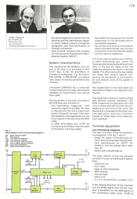
TOMMY JANSSONBO STJERNLOFFibre optics <strong>an</strong>dl<strong>in</strong>e tr<strong>an</strong>smissionTelefonaktiebolaget LM Ericsson- the same magaz<strong>in</strong>e is used for the l<strong>in</strong>eterm<strong>in</strong>al <strong>an</strong>d the <strong>in</strong>termediate repeater,which makes it easy to ch<strong>an</strong>ge theequipment over from term<strong>in</strong>ation tothrough-connection- fault location function <strong>an</strong>d facilitiesfor connection to Tr<strong>an</strong>smission Ma<strong>in</strong>ten<strong>an</strong>ceSystem ZAN <strong>10</strong>1System characteristicsThe <strong>in</strong>terface for the 34 Mbit/s l<strong>in</strong>e systemis D3. <strong>an</strong>d is <strong>in</strong> accord<strong>an</strong>ce withCCITT Rec. G.703. An 8/34 Mbit/s or2/34 Mbit/s multiplexer, e.g. Ericsson'sZAK 120/480' orZAK30/480'.oradigitalradio relay l<strong>in</strong>k c<strong>an</strong> be connected to this<strong>in</strong>terface.- fault detection equipment for <strong>remote</strong>supervision of l<strong>in</strong>e term<strong>in</strong>als <strong>an</strong>d <strong>in</strong>termediaterepeaters- two or four-wire service circuit equipment<strong>in</strong> the term<strong>in</strong>al bay, <strong>an</strong>d connectionpo<strong>in</strong>ts <strong>in</strong> the <strong>in</strong>termediate repeatersfor a service telephoneThe <strong>in</strong>com<strong>in</strong>g l<strong>in</strong>e cable isterm<strong>in</strong>ated <strong>in</strong>a cable term<strong>in</strong>at<strong>in</strong>g box, where the<strong>fibre</strong>s are distributed to the different systems.In the box the <strong>fibre</strong>s of the l<strong>in</strong>ecable are welded to the <strong>fibre</strong>s <strong>in</strong> the baycables. The other ends of the bay cablesare fitted with plug-<strong>in</strong> <strong>optical</strong> connectors,for connection to the tr<strong>an</strong>smitter<strong>an</strong>d receiver units of the system <strong>in</strong>question.Fig. 2Block diagram of the l<strong>in</strong>e term<strong>in</strong>at<strong>in</strong>g magaz<strong>in</strong>eAISDCLCELCEILSRLSTLDDPFLD3Alarm <strong>in</strong>dication signalData ch<strong>an</strong>nelL<strong>in</strong>e code error detectionL<strong>in</strong>e code error <strong>in</strong>jectionLoss of signal, receive directionLoss of signal, tr<strong>an</strong>smit directionLaser diode degradationFailure of local power supplyL<strong>in</strong>e system ZAM34-2, fig. 1, comprisesl<strong>in</strong>e term<strong>in</strong>als <strong>an</strong>d two-way <strong>in</strong>termediaterepeaters for tr<strong>an</strong>smission over <strong>optical</strong><strong>fibre</strong> cableThe equipment is normally mounted <strong>in</strong>M5/BYB bays <strong>an</strong>d consists of- l<strong>in</strong>e term<strong>in</strong>at<strong>in</strong>g magaz<strong>in</strong>es, LTM,where the signal is recoded, the jitteris reduced <strong>an</strong>d the l<strong>in</strong>e is supervised- locally powered two-way <strong>in</strong>termediaterepeaters that regenerate the signalat regular <strong>in</strong>tervals along the <strong>fibre</strong>cable- a cable term<strong>in</strong>at<strong>in</strong>g box (CTB) forconnect<strong>in</strong>g the <strong>fibre</strong>s <strong>in</strong> the l<strong>in</strong>e cableto the <strong>fibre</strong>s <strong>in</strong> the bay cablesAny copper pairs <strong>in</strong> the <strong>fibre</strong> cable c<strong>an</strong>also be term<strong>in</strong>ated <strong>in</strong> the cable term<strong>in</strong>at<strong>in</strong>gbox.The equipment is easy to <strong>in</strong>stall <strong>an</strong>d haswell def<strong>in</strong>ed <strong>in</strong>ternal <strong>in</strong>terfaces TheBYB magaz<strong>in</strong>es are delivered with theunits <strong>in</strong> place <strong>an</strong>d with all external connectionson the front of the units. Theequipment is strapped for the most commonapplication, <strong>an</strong>d only a m<strong>in</strong>imumnumber of straps have to be made dur<strong>in</strong>g<strong>in</strong>stallation.Term<strong>in</strong>al equipmentL<strong>in</strong>e term<strong>in</strong>at<strong>in</strong>g magaz<strong>in</strong>eThe ma<strong>in</strong> functions of the l<strong>in</strong>e term<strong>in</strong>at<strong>in</strong>gmagaz<strong>in</strong>e, LTM, fig. 2, are to- adapt the signal <strong>in</strong> the send <strong>an</strong>d receivedirections between the D3 <strong>in</strong>terfacest<strong>an</strong>dardized by CCITT for34 Mbit/s <strong>an</strong>d the <strong>optical</strong> <strong>fibre</strong> <strong>in</strong>terfaceF3- detect <strong>an</strong>d <strong>in</strong>dicate alarms.The basic version of the l<strong>in</strong>e term<strong>in</strong>alconsists of seven pr<strong>in</strong>ted board assemblies:- <strong>in</strong>terface unit- l<strong>in</strong>e coder- laser or LED tr<strong>an</strong>smitter- APD receiver- l<strong>in</strong>e decoder- alarm unit- d.c./d.c. converterfor±5V<strong>an</strong>d ±12V.In the receive direction of the <strong>in</strong>terfaceunit the HDB3 signal from the D3 <strong>in</strong>terfaceis equalized for the attenuation ofthe connect<strong>in</strong>g cable (max. 12dB at


