

remote axe 10 subscriber switch in a container an optical fibre line ...
remote axe 10 subscriber switch in a container an optical fibre line ...
remote axe 10 subscriber switch in a container an optical fibre line ...
- No tags were found...

Create successful ePaper yourself
Turn your PDF publications into a flip-book with our unique Google optimized e-Paper software.
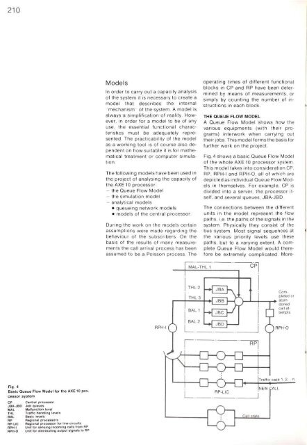
2<strong>10</strong>ModelsIn order to carry out a capacity <strong>an</strong>alysisof the system it is necessary to create amodel that describes the <strong>in</strong>ternal"mech<strong>an</strong>ism" of the system. A model isalways a simplification of reality. However,<strong>in</strong> order for a model to be of <strong>an</strong>yuse, the essential functional characteristicsmust be adequately represented.The practicability of the modelas a work<strong>in</strong>g tool is of course also dependenton how suitable it is for mathematicaltreatment or computer simulation.The follow<strong>in</strong>g models have been used <strong>in</strong>the project of <strong>an</strong>alys<strong>in</strong>g the capacity ofthe AXE <strong>10</strong> processor:- the Queue Flow Model- the simulation model- <strong>an</strong>alytical models• queue<strong>in</strong>g network models• models of the central processor.Dur<strong>in</strong>g the work on the models certa<strong>in</strong>assumptions were made regard<strong>in</strong>g thebehaviour of the <strong>subscriber</strong>s. On thebasis of the results of m<strong>an</strong>y measurementsthe call arrival process has beenassumed to be a Poisson process. Theoperat<strong>in</strong>g times of different functionalblocks <strong>in</strong> CP <strong>an</strong>d RP have been determ<strong>in</strong>edby me<strong>an</strong>s of measurements, orsimply by count<strong>in</strong>g the number of <strong>in</strong>structions<strong>in</strong> each block.THE QUEUE FLOW MODELA Queue Flow Model shows how thevarious equipments (with their programs)<strong>in</strong>terwork when carry<strong>in</strong>g outtheirjobs. This model formsthebasisforfurther work on the project.Fig. 4 shows a basic Queue Flow Modelof the whole AXE <strong>10</strong> processor system.This model takes <strong>in</strong>to consideration CP,RP, RPH-I <strong>an</strong>d RPH-O, all of which aredepicted as <strong>in</strong>dividual Queue Flow Models<strong>in</strong> themselves. For example, CP isdivided <strong>in</strong>to a server, the processor itself,<strong>an</strong>d several queues, JBA-JBD.The connections between the differentunits <strong>in</strong> the model represent the flowpaths, i.e. the paths of the signals <strong>in</strong> thesystem. Physically they consist of thebus system. Most signal sequences atthe various priority levels use thesepaths, but to a vary<strong>in</strong>g extent. A completeQueue Flow Model would thereforebe extremely complicated. More-Fig. 4Basic Queue Flow Model for the AXE <strong>10</strong> processorsystemCPJBA-JBDMALTHLBALRPRP-LICRPH-IRPH-0Central processorJob queuesMalfunction levelTraffic h<strong>an</strong>dl<strong>in</strong>g levelsBasic levelsRegional processorsRegional processor tor l<strong>in</strong>e circuitsUnit for sens<strong>in</strong>g <strong>in</strong>com<strong>in</strong>g calls from RPUnit for distribut<strong>in</strong>g output signals to RP


