Specifications Sheet - Liquid Controls
Specifications Sheet - Liquid Controls
Specifications Sheet - Liquid Controls
- No tags were found...

You also want an ePaper? Increase the reach of your titles
YUMPU automatically turns print PDFs into web optimized ePapers that Google loves.
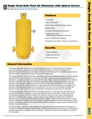
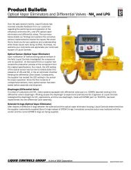
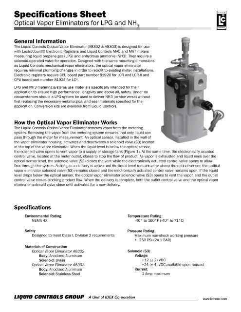
<strong>Specifications</strong> <strong>Sheet</strong>Optical Vapor Eliminators for LPG and NH 3General InformationThe <strong>Liquid</strong> <strong>Controls</strong> Optical Vapor Eliminator (A8302 & A8303) is designed for usewith LectroCount® Electronic Registers and <strong>Liquid</strong> <strong>Controls</strong> MA5 and MA7 metersmeasuring liquid propane gas (LPG) and anhydrous ammonia (NH3). They require asolenoid-operated valve for operation. Designed with the same mounting dimensionsas <strong>Liquid</strong> <strong>Controls</strong> mechanical vapor eliminators, the optical vapor eliminatorrequires minimal plumbing changes in order to retrofit to existing meter installations.Electronic registers require CPU board part number 81920 for LCR and LCR-II andCPU board part number 81924 for LC³.LPG and NH3 metering systems use materials specifically intended for theirapplication to ensure high performance, longevity and above all, safety. Under nocircumstances should a LPG system be used to deliver NH3 (or vice versa) withoutfirst replacing the necessary metallurgical and seal materials specified for theapplication. Conversion kits are available from <strong>Liquid</strong> <strong>Controls</strong>.How the Optical Vapor Eliminator WorksThe <strong>Liquid</strong> <strong>Controls</strong> Optical Vapor Eliminator removes vapor from the meteringsystem. Removing the vapor from the metering system ensures that only liquid canpass through the meter for measurement. An optical sensor, installed in the wall ofthe vapor eliminator housing, activates and deactivates a solenoid valve (S3) locatedat the top of the vapor eliminator. When the liquid level is below the optical sensor,the solenoid valve opens to vent vapor to a supply or storage tank (Figure 1). At the same time, the electronically acuatedcontrol valve, located at the meter outlet, closes to stop the flow of product. As vapor is exhausted and liquid rises over theoptical sensor level, the solenoid valve (S3) closes the vent while the electronically actuated control valve opens to allowflow through the system. As long as a delivery is active and the liquid level remains at or above the optical sensor, the opticalvapor eliminator solenoid valve (S3) remains closed and the electronically actuated control valve remains open. If the liquidlevel drops below the optical sensor, the optical vapor eliminator solenoid valve (S3) opens to vent the vapor, and the outletcontrol valve closes blocking product flow. When the delivery is complete, both the outlet control valve and the optical vaporeliminator solenoid valve close until activated for a new delivery.<strong>Specifications</strong>Environmental RatingNEMA 4XSafetyDesigned to meet Class I, Division 2 requirementsMaterials of ConstructionOptical Vapor Eliminator A8302Body: Anodized AluminumSolenoid: BrassOptical Vapor Eliminator A8303Body: Anodized AluminumSolenoid: Stainless SteelTemperature Rating-40° to 160°F (-40° to 71°C)Pressure RatingMaximum non-shock working pressure• 350 PSI (24.1 BAR)Solenoid (S3)Voltage:+12 (± 2) VDC+24 (± 4) VDC available upon requestCurrent:1 Amp maximum
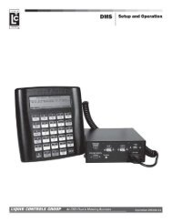
Dimensional DrawingsTOPREARSIDEDimensions shown are not for construction use.Consult factory when certified engineering drawings are required.105 Albrecht DriveLake Bluff, IL 60044-22421.800.458.5262 • 847.295.1050Fax: 847.295.1057www.lcmeter.com© 2008 <strong>Liquid</strong> <strong>Controls</strong>Pub. No. 500353(05/01/08)