LectroCount Remote Display - Liquid Controls
LectroCount Remote Display - Liquid Controls
LectroCount Remote Display - Liquid Controls
- No tags were found...

You also want an ePaper? Increase the reach of your titles
YUMPU automatically turns print PDFs into web optimized ePapers that Google loves.
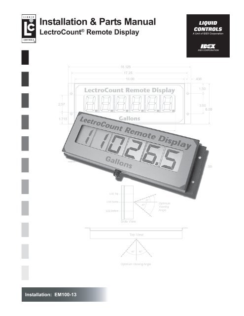
SpecificationsThe <strong>LectroCount</strong> <strong>Remote</strong> <strong>Display</strong> is a 6-digit, backlit display with 2¼" high digits, viewable to 100 ft, for flow meteringapplications.<strong>LectroCount</strong> <strong>Remote</strong> <strong>Display</strong> models are available for <strong>LectroCount</strong> LCR ® , <strong>LectroCount</strong> LCR-II ® and <strong>LectroCount</strong>³Electronic Registers.Model E1610 - For use with <strong>LectroCount</strong> LCR-IIModel E1611 - For use with <strong>LectroCount</strong> LCR and <strong>LectroCount</strong>³Features include:• 6-digit, backlit display with 2¼" high display characters.• 30 ft, 4-wire, shielded cable.• Class I, Division 2 Group C & D weatherproof NEMA 4X enclosure.• Weights & Measures Approvals in USA and Canada when used with <strong>LectroCount</strong> Electronic Registers.• Viewable up to 100 ft.Wiring: Connections from the <strong>LectroCount</strong> register to the <strong>LectroCount</strong> <strong>Remote</strong> <strong>Display</strong> should be made using 22gage, 4-wire, shielded cable or larger. Thirty feet of cable is provided with the display. The maximum length of cableallowable is 100 ft. The 4-wire cable includes conductors for power, ground, and two signals.Figure 2. <strong>LectroCount</strong> <strong>Remote</strong> <strong>Display</strong>SPECIFICATIONSEnvironmentalDesign for:Class I, Div. 2, Group C & DNEMA 4XSignal InputInput Signal Levels:Hi ≥ 2.50 VDCLo ≤ 2.0 VDCOperating Temp. Range*:-22º to 158º F-30º to 70º CApprovalsUS Weights & Measures: NTEP COC 86-022Canada Weights & Measures: AV-2342ElectricalPower:+5 to 15 VDC, 500 mA, MaximumMaximum Frequency Input:Signal Source:<strong>LectroCount</strong> LCR<strong>LectroCount</strong> LCR-II<strong>LectroCount</strong> LC 3Frequency5 kHzN/A5 kHz*At lower temperatures, the liquid crystal display may have a delayedresponse rate.3
Installation! CAUTIONThe <strong>LectroCount</strong> <strong>Remote</strong> <strong>Display</strong> and accessories (whether supplied by <strong>Liquid</strong> <strong>Controls</strong> or other) must be installedand operated in accordance with all applicable federal, state, and local construction, electrical, environmentaland safety codes. Failure to do so could result in serious injury or death.This unit is designed for Class I, Division 2, Group C & D areas.Do not install in Class I, Division 1 areas.Installation Requirements• Read this manual prior to start of installation. If youhave any questions, consult with your full servicedistributor or call the Service Department at <strong>Liquid</strong><strong>Controls</strong>.• This display should always be securely mounted toa platform or supportive member. Ensure that thedisplay does not experience excessive vibration orshock.• The <strong>LectroCount</strong> <strong>Remote</strong> <strong>Display</strong> is designed to becompatible with a specific <strong>LectroCount</strong> ElectronicRegister as specified by the customer and asindicated on the Serial Number Tag. No attemptshould be made to use the display with an inputdifferent from the one originally specified.• The <strong>LectroCount</strong> <strong>Remote</strong> <strong>Display</strong> is supplied with a30 foot cable, which should be adequate for mostinstallations. If additional cable is required, cablekits are available from <strong>Liquid</strong> <strong>Controls</strong>. It isrecommended that a 4-wire, shielded cable with 22gage wire or larger be used. The maximum lengthof cable allowable is 100 feet.The <strong>LectroCount</strong> <strong>Remote</strong> <strong>Display</strong> is supplied ready forfinal cable termination. Should it be necessary to replacethe cable between the signal source and the remotedisplay, be sure to secure the cable and tighten the coverso as to maintain the vapor seal.<strong>Remote</strong> <strong>Display</strong> LabelThe <strong>LectroCount</strong> <strong>Remote</strong> <strong>Display</strong> is shipped with the unitsof measure displayed on the label in Gallons. Theapplication in which the display is being utilized mayrequire a different unit of measure.The <strong>LectroCount</strong> <strong>Remote</strong> display is shipped with four (4)additional unit of measure labels. To change the unit ofmeasure, remove the desired label from it’s backing andplace over the “Gallons” label on the display. The areaaround Gallons is recessed and the sticker can easilybe positioned for placement.Figure 3. <strong>Remote</strong> <strong>Display</strong> Label4
InstallationMounting DimensionsThe <strong>LectroCount</strong> <strong>Remote</strong> <strong>Display</strong> should be mountedusing the four holes provided in the rear cover. The holesize is designed for use with ¼" screws. It is importantto select a mounting location which will position thedisplay as close to the optimal viewing angle as possible(see Page 6).The diagram below shows the overall dimensions andthe locations of the mounting holes on the <strong>LectroCount</strong><strong>Remote</strong> <strong>Display</strong>.Figure 4. <strong>Remote</strong> <strong>Display</strong> DimensionsNOTE:Dimensions shown are not for construction use.Consult factory when certified Engineering Drawings are required.5
InstallationOptimum Viewing AngleLCD displays have an optimum viewing angle. <strong>Display</strong>slose contrast and become more difficult to read at someviewing angles and are easier to read at other angles.Because the viewing angle is limited, a bias is designedinto the module at the time it is manufactured. The resultis a nominal viewing angle which is offset from theperpendicular by a specified amount. The <strong>Liquid</strong> <strong>Controls</strong><strong>LectroCount</strong> <strong>Remote</strong> <strong>Display</strong> is designed with a bias setto accommodate as wide a viewing area as possible.Optimum viewing with the greatest contrast will occurwhen the display is viewed between 20º above and 40ºbelow horizontal. If the display is viewed outside thisrange, the display contrast will reduce to a point where itreaches an unacceptable viewing level. The horizontal,side to side viewing angle is 40º left and right from center.Figure 5. Optimum Viewing Angle6
Installation<strong>Remote</strong> <strong>Display</strong> Shield Accessory (PN 81879)There are certain applications where sun or bright lightmay produce glare on the display. Use the optional shieldto reduce the effect of glare. This shield fits in place overthe <strong>LectroCount</strong> <strong>Remote</strong> <strong>Display</strong> as shown in Figure 6.The holes in the shield are slotted for ease of installation.Figure 6. <strong>Remote</strong> <strong>Display</strong> ShieldFigure 7. <strong>Remote</strong> <strong>Display</strong> Shield DimensionsNOTE: Dimensions shown in Inches (to obtain centimeters, multiply values shown by 2.54).Bolt & Torque SpecificationsIt may be necessary to open the <strong>Remote</strong> <strong>Display</strong> for thepurpose of changing the decimal point jumper setting(Page 8), or to connect wires to J1 or J2. There are 14bolts on the rear panel of the <strong>Remote</strong> <strong>Display</strong> which needto be removed to gain access to the printed circuit board(PCB). When work on the internal components iscomplete, the bolts need to be tightened to the propertorque specification and in the proper sequence to ensurethat the unit is resealed properly to prevent moisture fromentering.Insert each bolt and tighten by hand, then tighten thebolts according to the sequence show below. The boltsshould be tightened to 5-8 In. LBS. (80-128 In. Oz.)Figure 8. <strong>Remote</strong> <strong>Display</strong> Torque Pattern.7
InstallationDecimal Point Jumper SettingNOTE: Model E1610 automatically displays the identicaldecimal configuration appearing on the <strong>LectroCount</strong>LCR-II display. There is no need to adjust the jumperson Model E1610.The <strong>LectroCount</strong> <strong>Remote</strong> <strong>Display</strong> may be configured toshow the decimal point in one of three positions:• Whole Units (No Decimal Point)• Tenth Units• Hundredth UnitsThis is accomplished by moving the J3 and J4 jumperson the <strong>Remote</strong> <strong>Display</strong> PCB. The PCB is accessed byremoving the 14 screws on the back of the enclosure.The jumpers are located on the bottom left side of thePCB, to the left of the J2 connector (Figure 9).Once the enclosure is opened, the jumpers may be movedto configure the display according to the <strong>LectroCount</strong>Electronic Register for which it is designed. See the tablebelow for jumper settings.NOTE: The jumpers need to be in position. Do not removeand discard them. If Whole Units is desired, then J3 andJ4 must BOTH have jumpers in the OFF position.NOTE: If J3 and J4 are BOTH in the ON position, then 2decimal points will appear on the display. This is not avalid jumper configuration.Figure 9. Jumper LocationsJ3 J4 J2DEVICEMODEL No.Whole Units Tenth Units Hundreth UnitsJ3 J4 J3 J4 J3 J4<strong>LectroCount</strong> LCR-II E1610 OFF OFF OFF OFF OFF OFF<strong>LectroCount</strong> LCR,<strong>LectroCount</strong>³E1611 OFF OFF ON OFF OFF ONTable 1. Decimal Point Jumper Setting.8
Wiring DiagramsModel No. E1610For use with <strong>LectroCount</strong> LCR-IIOnce the display is mounted, the factory installedcable should be routed to the <strong>LectroCount</strong> LCR-II. Choose an unused port on the LCR-II andconnect the cord grip provided. Route the cablethrough the cord grip and connect the cable tothe J12 Connector on the LCR-II PCB as shownin Figure 10.J12Pin 39Pin 40Pin 41Pin 45*J1Pin 21 (WHITE)Pin 22 (GREEN)Pin 23 (BLACK)Pin 20 (RED)*If the power supplied to the LCR-II ever exceeds+24VDC, then the remote display should be poweredfrom Pin 32 on J8, +5VDC.Figure 10. LCR-II Wiring Diagram<strong>LectroCount</strong> LCR-II - Select Switch Kit Accessory (PN 82593)This kit is not required for operation of the <strong>LectroCount</strong><strong>Remote</strong> <strong>Display</strong> with the <strong>LectroCount</strong> LCR-II. It is anoptional accessory which allows the user to select thevarious displays available from a remote location. Theswitch kit accessory does not connect to the <strong>LectroCount</strong><strong>Remote</strong> <strong>Display</strong>, it is wired directly into the <strong>LectroCount</strong>LCR-II.The Select Switch Kit includes the following:• Push Button (& cord grip)• Cord Grip (2)• 4-port Conduit Box• 30 Foot, 2-wire, Shielded CableThe 4-port Conduit Box can be configured as desired.Each port is the same size (½") so the plugs and cord gripand switch may be reconfigured to suit the application.When a location has been determined for the switch kit,mount the conduit box. Route the 30 foot cable providedto the <strong>LectroCount</strong> LCR-II and connect the cord grip to anavailable port on the back of the LCR-II. Route the freeend of the 30 foot cable through the cord grip on the backof the LCR-II. Connect the two wires for the Select switchto terminal J8 on the LCR-II PCB as shown in Figure 11.RED to Pin 35BLACK to Pin 38.Figure 11. Select Switch Wiring DiagramWhen a delivery is active, pressing the Select Switch willcause the display to show the current flow rate. After 5seconds, the display returns to current flow total.9
Wiring DiagramsModel No. E1611For use with <strong>LectroCount</strong> LCROnce the display is mounted, the cable shouldbe routed to the LCR. Choose an unused porton the LCR and connect the cord grip provided.Route the cable through the cord grip andconnect the cable to the J12 Connector on theLCR PCB as shown in Figure 12.J12Pin 39Pin 40Pin 41Pin 45*J1Pin 21 (WHITE)Pin 22 (GREEN)Pin 23 (BLACK)Pin 20 (RED)When functional, the remote display will match the LCRdisplay. No external reset switch is required for operation.Figure 12. LCR Wiring Diagram*If the power supplied to the LCR ever exceeds +24VDC,then the remote display should be powered from Pin 32on J8, +5VDC.Model No. E1611For use with <strong>LectroCount</strong>³Once the display is mounted, the cable shouldbe routed to the <strong>LectroCount</strong>³. Choose anunused port on the LC³ and connect the cordgrip provided. Route the cable through the cordgrip and connect the cable to the J1 Connectoron the <strong>LectroCount</strong>³ PCB as shown in Figure 13.J1 (LC³)Pin 1Pin 2Pin 5Pin 6J1 (<strong>Remote</strong> <strong>Display</strong>)Pin 20 (RED)Pin 23 (BLACK)Pin 21 (WHITE)Pin 22 (GREEN)When functional, the remote display will match the LC³display. No external reset switch is required for operation.Figure 13. LC³ Wiring Diagram10
Dual <strong>Display</strong> KitDual <strong>Display</strong> Kit (PN 82594)(For use with Models E1610 & E1611)The Dual <strong>Display</strong> Kit is designed for use with two (2)<strong>LectroCount</strong> <strong>Remote</strong> <strong>Display</strong>s and a single <strong>LectroCount</strong>Electronic Register. This kit contains:• 4-Port Junction Box• Cord Grip (2)• Nipple & Seal WasherThe <strong>LectroCount</strong> <strong>Remote</strong> <strong>Display</strong>s are equipped with a30 ft, 4-wire, shielded cable.To install the Dual <strong>Display</strong> Kit:1. Open one of the units by removing the 14 bolts onthe back panel.2. Disconnect the cable from J1.3. Remove the cord grip and cable from the unit.4. Install the 4-Port Junction Box in the space wherethe cord grip was just removed.5. Route the cable from the unopened <strong>Remote</strong> <strong>Display</strong>through a cord grip attached to the junction box.6. Route the removed cable through a second cord gripin the junction box.7. Connect both cables to J1 on the PCB.J1Pin 20 - Red WirePin 21 - White WirePin 22 - Green WirePin 23 - Black Wire8. Replace the cover on the back of the display followingthe specifications on Page 7.9. Connect the loose end of the cable to the <strong>LectroCount</strong>Electronic Register as shown on Pages 9-10.Figure 14. Dual <strong>Display</strong> Kit - 2 <strong>Remote</strong> <strong>Display</strong>s with 1 <strong>LectroCount</strong> Electronic Register11
Illustrated Parts BreakdownA Unit of IDEX Corporation105 Albrecht DriveLake Bluff, IL 60044-22421.800.458.5262 • 847.295.1050Fax: 847.295.1057www.lcmeter.com© 2007 <strong>Liquid</strong> <strong>Controls</strong>Pub. No. 500316(07/20/07)