Assembly Instructions - Swing-N-Slide
Assembly Instructions - Swing-N-Slide
Assembly Instructions - Swing-N-Slide

Create successful ePaper yourself
Turn your PDF publications into a flip-book with our unique Google optimized e-Paper software.
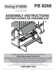
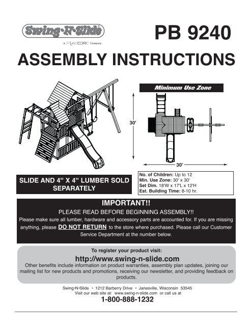
PB 9240ASSEMBLY INSTRUcTIONSMinimum Use Zone30'30'SLIDE AND 4'' X 4'' LUMBER SOLDSEPARATELYNo. of children: Up to 12Min. Use Zone: 30' x 30'Set Dim. 18'W x 17'L x 12'HEst. Building Time: 8-10 hr.IMPORTANT!!PLEASE READ BEFORE BEGINNING ASSEMBLY!!Please make sure all lumber, hardware and accessory parts are accounted for. If you are missinganything, please DO NOT RETURN to the store where purchased. Please call our CustomerService Department at the number below.To register your product visit:http://www.swing-n-slide.comOther benefits include information on product warranties, assembly plan updates, joining ourmailing list for new products and promotions, receiving our newsletter, and providing feedback onproducts.<strong>Swing</strong>•N•<strong>Slide</strong> • 1212 Barberry Drive • Janesville, Wisconsin 53545Visit our web site at: www.swing-n-slide.com or call us at1-800-888-1232
Safety Checklist for <strong>Swing</strong>-N-<strong>Slide</strong> Play Sets and AccessoriesObserving the following statements and warnings reduces the likelihood of serious or fatal injuryInstallation Safety – Have You:Consulted the assembly instructions supplied with your particular model?Noted this accessory is to be used only on <strong>Swing</strong>•N•<strong>Slide</strong> approved designs? (Do not alter its design or add/remove components.)Made sure all hardware is tightened securely? (Supplied bolt covers must also be fastened securely.)Using a hacksaw, cut off all protruding threaded ends of bolts and other fasteners and remove any sharp edges witha metal file as needed, and coated fastener ends with lead free paint?Placed the equipment on level ground, not less than six feet (1.8 meters) from any structure or obstruction such as a fence, garage,house, overhanging branches, laundry lines, or electrical wires?Made sure home playground equipment is not installed over concrete, asphalt, packed earth or any other hard surface? (A fall ontoa hard surface can result in serious injury to the equipment user.)Verified that suspended climbing ropes, chain,or cable are secured at both ends?Consulted in assembly instructions of your particular model for minimum use zones?Used a water sealant on your play set to protect the wood and prevent cracking and warping?Followed all anchoring and shock absorbing surfacing requirements on the back of this sheet as they apply?Made sure not to allow children to use equipment until it is properly installed?Made sure to adjust all swings so there is a minimum 8'' clearance between the swing and the ground surface?Operating Safety – Have You:Determined that on-site adult supervision is provided for children of all ages?Warned children the following before allowing them to use the equipment?Not to walk close to, in front of, behind or between moving items.Not to twist swing or any other accessory chains or ropes or loop them over the top support bar since this will reduce thestrength of chain or rope.Not to swing empty seats or other accessories.Not to slide down swing chains.Be sure to sit in the center of the swing seat and other accessories with full weight on the seat.Not to attach items to the playground equipment that are not specifically designed for use with the equipment such as but notlimited to, jump ropes, clotheslines, pet leashes, cables and chain. They may cause a strangulation hazard.Not to climb or walk on the top of swing beams, railings or roof.Not to use equipment in a manner other than intended.Not to get off equipment while it is in motion.Not to climb on the equipment when it is wet.Be sure to go down slides feet first.Determined that only one child per planned occupant seat should be allowed on this set at one time.Determined children must be dressed appropriately for play. Avoid hooded jackets, bicycle helmets, clothing with draw strings andloose fitting clothes which could become entangled or snagged on equipment.Determined that suspended climbing ropes, chain, or cable cannot be looped back upon itself.Made certain the slide is placed so that is is not in direct sunlight.Safety Maintenance – At the beginning of every season and twice monthly thereafter:Rake and check depth of loose fill protective surfacing material to prevent compaction and maintain appropriate depth. Replace asnecessary.Check all nuts, bolts and C-Links during the usage season for tightness and tighten as required. (It isparticularly important that this procedure be followed at the beginning of each season.)To prevent the deterioration of materials, remove plastic swing seats and other plastic accessories when outdoors temp dips down toor below 32° F and take indoors.Oil all metallic moving parts monthly during usage period.Check all hardware and equipment for sharp edges during usage season. (Replace when necessary. It is especiallyimportant to do this at the beginning of each new season.)Check swing seats, chains, ropes and cables monthly during usage season for evidence of deterioration. Severe rusting or excessive wear,especially near the top swing hanger or at the seat connection are evidence of chain deterioration. Cracks in the protective plastic sleeveor seat itself are also signs of deterioration. If any of these conditions exist, call 1-800-888-1232 to order replacement accessories.Sand rusted metal parts and repaint using non-lead based paint.Check all wood members for deterioration and splinters. Sand down splinters and replace deteriorating wood members.Disposal <strong>Instructions</strong>When the equipment is taken out of service, it must be disassembled and disposed of in such a way that no unreasonable hazardswill exist at the time the set is discarded.Important! Additional Safety <strong>Instructions</strong> for all <strong>Swing</strong>-N-<strong>Slide</strong> Playground Equipment.Save this instruction sheet in the event the manufacturer needs to be contacted.2
This product is intended for single family home/residential use only and not intended for use in any public setting.Placement in any public setting constitutes a misuse of this product.IMPORTANT!ADDITIONAL REQUIRED SAFETY INSTALLATION INSTRUCTIONSAccording to ASTM requirements, all kits must be anchored to the ground and, if the unit has a climbing rope, the rope end must be anchored to the ground. If soil conditionspermit stakes to be pulled out easily, cementing into ground is necessary.• To anchor the unit to the ground, Follow the instructions included in this plan for applying Anchor-It devices to your unit, or use 2" x 4" x 18" (45mm x 95mm x 457mm) pressuretreatedstakes. Pound stakes into ground at least 12" (305mm) at all inside corners of the posts (including A-frame legs and climbing unit posts). Attach with four (4) 16D (3-1/2")galvanized nails per stake into each tower and/or A-frame upright.• If the unit has a climbing rope, anchor the rope end.• Once the unit is completely assembled and before children are allowed to play on it, proper shock-absorbing surfacing material must be installed. This may be accomplished byusing loose-fill materials at a sufficient depth. The Consumer Product Safety Commission “Handbook for Public Playground Safety” lists the following materials and requireddepths that are sufficient for home/residential application. For fall height protection up to 9 ft. (2.742m) [recommended for <strong>Swing</strong>•N•<strong>Slide</strong> kits]:LOOSE FILL MATERIALREQUIRED (UNCOMPRESSED) DEPTH 1 in. (mm)Wood Mulch9" (229mm)Double Shredded Bark Mulch9" (229mm)Uniform Wood Chips12" (305mm)Fine Sand12" (305mm)Fine Gravel12" (305mm)These depths were derived from the CPSC Handbook. <strong>Swing</strong>•N•<strong>Slide</strong> has not done independent tests to determine these required depths.When properly installed, shock absorbing material will completely cover the horizontal baseboards on climbing units. This protective surfacing must extend a minimum of 6 ft.(1.828m) in all directions from the perimeter of the equipment or from the outermost edges of any component. For example, a slide extending beyond the platform must haveprotective surfacing at least 6 ft. (1.828mm) out from both sides as well as the end. For swings, the protective surface must extend at least 14 ft. (6m) out from both the back andfront of the swing when the swing is in its rest position.For further information on playground safety, the Consumer Product Safety Commission(CPSC) publishes the Outdoor Home Playground Safety Handbook which can be downloaded for freefrom www.cpsc.gov. An additional resource is the American Society of Testing and Materials (ASTM)Standard Consumer Safety Performance Specification for Home Playground Equipment (ASTM F1148)which can be purchased and downloaded from www.astm.org.<strong>Swing</strong>-N-<strong>Slide</strong>® MANUFACTURERS LIMITED WARRANTY<strong>Swing</strong>-N-<strong>Slide</strong>® takes great pride in the quality and durability of our products. Our Manufacturer’s Limited Warranty provides confidence and demonstrates our commitmentto providing quality residential playground products.MANUFACTURER’S LIFETIME LIMITED WARRANTY<strong>Swing</strong>-N-<strong>Slide</strong>® warrants its thermoformed slides and climbing mountains to be free from defects in workmanship and materials, under normal use and conditions, for thelifetime of the product.MANUFACTURER’S 5 YEAR LIMITED WARRANTY<strong>Swing</strong>-N-<strong>Slide</strong>® warrants its Custom Ready-to-Build Play Set kits and accessories to be free from defects in workmanship and materials, under normal use and conditions,for a period of 5 years.MANUFACTURER’S 5 YEAR LIMITED WARRANTY<strong>Swing</strong>-N-<strong>Slide</strong>® warrants its No-Cut and Wood Complete Ready-to-Assemble Play Set kits against wood rot and termite damage, and to be free from defects inworkmanship and materials, under normal use and conditions, for a period of 5 years for structural wood components.Cosmetic defects that do not affect the structural integrity of the product, or natural defects of wood such as warping, splitting, checking, twisting, shrinkage, swelling orany other physical properties of wood that do not present a safety hazard, are not covered by this warranty.MANUFACTURER’S ONE YEAR WARRANTY<strong>Swing</strong>-N-<strong>Slide</strong>® warrants its canopy roofs and/or tarps, and Timber GLOVE lumber wrap to be free from defects in workmanship and materials, under normal use andconditions, for a period of one year.<strong>Swing</strong>-N-<strong>Slide</strong>® will repair, or at its discretion, replace any part within the stated warranty period which is defective in workmanship or materials. This decision is subjectto verification of the defect upon delivery of the defective part to <strong>Swing</strong>-N-<strong>Slide</strong>® at 1212 Barberry Drive, Janesville, Wisconsin, 53545. Any part(s) returned to <strong>Swing</strong>-N-<strong>Slide</strong>® must have prior approved Return Authorization Number and proof of purchase, including the date of purchase. This warranty is valid only if the product is used forthe purpose for which it was designed and installed at a residential, single family dwelling. This warranty is void if the product is put to commercial or institutional use. Thiswarranty does not cover (a) products which have been damaged by acts of Nature, negligence, misuse, or accident, or which have been modified or repaired byunauthorized persons; (b) the cost of labor; or the cost of shipping the product, any part, or any replacement product or part.<strong>Swing</strong>-N-<strong>Slide</strong>® DISCLAIMS ALL OTHER REPRESENTATIONS AND WARRANTIES OF ANY KIND, EXPRESS, IMPLIED, STATUTORY OR OTHERWISE, INCLUDING THEIMPLIED WARRANTIES OF MERCHANTIBILITY AND FITNESS FOR A PARTICULAR PURPOSE. <strong>Swing</strong>-N-<strong>Slide</strong>® WILL NOT BE LIABLE FOR ANY INCIDENTAL ORCONSEQUENTIAL DAMAGES. This warranty is non-transferable and does not extend to the owners of the product subsequent to the original purchaser. Some states do notallow limitations on implied warranties or exclusion of incidental or consequential damages, so these restrictions may not be applicable to you. This warranty gives youspecific legal rights. You may also have other rights, which vary from state to state.This warranty also does not apply to:• Structures not erected, maintained or inspected in conformance with <strong>Swing</strong>-N-<strong>Slide</strong>® installation plans• Structures that have had parts added or substituted not in conformance with <strong>Swing</strong>-N-<strong>Slide</strong>® installation plans• Parts that have been modified, altered or misused• Parts that have not been used as designed or intended• Damage due to acts of Nature, vandalism, abnormal use or abuse as determined by <strong>Swing</strong>-N-<strong>Slide</strong>®3
TOOLS REQUIREDTOOLS REQUIREDUtility KnifeELEcTRIc DRILLHAMMER1/2" SOcKET & WRENcHTAPE MEASURESAFETY GLASSES& DUST MASKcARPENTER'S SQUAREPHILLIPS BIT1/8'' Drill Bit(70) 2" lag screw(4) 1-1/2'' Lag Bolt(10) Loc-Nuts(56) 1-1/4'' Lag Screw(353) 2-1/2'' screws(2) 1/2'' panhead screws(4) 1/4'' flat washers(51) 2'' Wood Screw(4) 1-3/4'' panhead screws(128) 1-1/2'' screws(486) 1-1/4'' screws(10) 5/16'' flat washers(8) 4-1/2'' Carriage Bolts(2) 4'' Carriage Bolts(10) Wood Loc Washers4
R(2) 4'' x 4'' Shelf-Loc(1) LH Split Beam bracket(8) 2'' x 4'' Shelf-Loc(4) Roof Bracket(1) RH Split Beam bracket(5) 13-7/8'' Ladder Rungs(4) 23-1/4'' Monkey Bar Rungs(10) Wrap-Loc(2) Boomerang Bracket(1) T20 Torx® Bit(1) Tailor’s Chalk(2) EZ Frame Brackets(1) T30 Torx® BitPB 9240PlanTHIS PRODUCT ISINTENDED FOR USEBY CHILDREN FROMAGES 2-10 YEARSFor Home / ResidentialUse ONLY1212 Barberry DriveJanesville, WI 535451-800-888-1232www.swing-n-slide.com(1) 3/8" DRILL BIT (5'' Min.)(1) Plan(1) Name Platewith Hardware5
<strong>Assembly</strong> <strong>Instructions</strong>(4) Extra-Duty<strong>Swing</strong> Hangers(1) 2 For Funwith Hardware150 lb Weight Limit(2) Heavy-Duty <strong>Swing</strong> Seatweight limit: 225 lbs.(3) Step Brackets(Left)(3) Step Brackets(Right)(5) 10' TimberGlove(4) 8' TimberGlove(2) 'L' Brackets(4) Anchor-It(4) Anchor-It Straps(2) Safety Bracket(2) Safety Handles(4) Quick Links(6) Climbing Rockswith Hardware6
(2) [PF 3911] 1’’ x 1’’ x 12’’ Cleat(2) [PF 3910] 5/4’’ x 4’’ x 28-1/4’’(3) [PF 3909] 2’’ x 4’’ x 23-3/8’’(1) [PF 3908] 2’’ x 4’’ x 11-7/8’’PB 9240 Board List<strong>Assembly</strong> <strong>Instructions</strong>(3) [PF 3885] 1’’ x 4’’ x 40-1/4’’ (1) [PF 3405] 4’’ x 4’’ x 47-1/2’’(2) [PF 3884] 1’’ x 4’’ x 40-1/4’’(6) [PF 3404] 2’’ x 4’’ x 47-1/2’’(8) [PF 3883] 1’’ x 4’’ x 40-1/4’’(3) [PF 3402] 2’’ x 4’’ x 30’’(2) [PF 3882] 1’’ x 4’’ x 40-1/4’’(1) [PF 3907] 5/4’’ x 6’’ x 47-1/2’’ Offset Arch(1) [PF 3906] 5/4’’ x 6’’ x 47-1/2’’ Center Arch(1) [PF 3905] 5/4’’ x 6’’ x 45-1/4’’ Center Arch(1) [PF 3904] 5/4’’ x 6’’ x 30’’ Center Arch(4) [PF 3903] 5/4’’ x 4’’ x 47-1/2’’(17) [PF 3902] 5/4’’ x 4’’ x 47-1/2’’(4) [PF 3901] 5/4’’ x 4’’ x 40’’(2) [PF 3900] 5/4’’ x 4’’ x 20-3/4’’(3) [PF 3899] 5/4’’ x 4’’ x 9’’ Chamfer(6) [PF 3898] 5/4’’ x 4’’ x 3-1/2’’ Chamfer(4) [PF 3897] 5/4’’ x 4’’ x 44-1/2’’(4) [PF 3896] 5/4’’ x 4’’ x 41-1/8’’(2) [PF 3895] 5/4’’ x 4’’ x 12’’(1) [PF 3894] 1’’ x 1’’ x 43’’(1) [PF 3893] 1’’ x 1’’ x 31-1/2’’(2) [PF 3892] 1’’ x 6’’ x 47-1/2’’(1) [PF 3891] 1’’ x 6’’ x 34-1/2’’(1) [PF 3890] 1’’ x 6’’ x 23’’(4) [PF 3889] 1’’ x 4’’ x 47-1/2’’(6) [PF 3888] 1’’ x 4’’ x 47-1/2’’(4) [PF 3887] 1’’ x 4’’ x 46-1/4’’ Angle(3) [PF 3886] 1’’ x 4’’ x 45-3/4’’(13) [PF 3881] 1’’ x 4’’ x 36’’(1) [PF 3880] 1’’ x 4’’ x 30’’(8) [PF 3879] 1’’ x 4’’ x 28-1/4’’(19) [PF 3878] 1’’ x 4’’ x 24’’(4) [PF 3877] 1’’ x 4’’ x 23-3/4’’(1) [PF 3876] 1’’ x 4’’ x 22-3/4’’(4) [PF 3875] 1’’ x 4’’ x 18-1/4’’ Angle(4) [PF 3874] 1’’ x 4’’ x 18’’(1) [PF 3873] 1’’ x 4’’ x 14-1/4’’(17) [PF 3872] 1’’ x 5’’ x 47-1/2’’ Shingle(1) [PF 3871] 1’’ x 5’’ x 47-1/2’’ Shingle Notch(10) [PF 3870] 1’’ x 5’’ x 26-1/2’’ Shingle(10) [PF 3869] 1’’ x 5’’ x 26-1/2’’ Shingle(1) [PF 3868] 1’’ x 5’’ x 21-1/2’’ Shingle RH(1) [PF 3867] 1’’ x 5’’ x 21-1/2’’ Shingle LH(1) [PF 3866] 1’’ x 5’’ x 18-1/2’’ Shingle RH(1) [PF 3865] 1’’ x 5’’ x 18-1/2’’ Shingle LH(2) [PF 3778] 2’’ x 4’’ x 20’’ 2 For Fun Support(2) [PF 3708] 2’’ x 4’’ x 47-1/2’’(1) [PF 3707] 2’’ x 4’’ x 30’’(1) [PF 3628] 1’’ x 4’’ x 20’’(1) [PF 3419] 2’’ x 4’’ x 17-1/4’’ <strong>Slide</strong> Stake7
<strong>Assembly</strong> <strong>Instructions</strong>Lumber Purchased Separately(4) 4’’ x 4’’ x 96’’(5) 4’’ x 4’’ x 120’’How to select the correct fastenerUse these 2 pictorial guides to help select the correct fastener(s) for thelumber attachment you are making. Each diagram will highlight the correctnumber of fasteners to use and where to attach them.5/4'' x 4'' to 4'' x 4''N OM INAL M ATERIAL SIZELISTED SIZET RUE SIZEE nglish(*) Metric(Cm) English(*) Metric(Cm)1x4 2.5x7.6 3/4x3-1/2 1.9x91x6 2.5x15.3 3/4x5-1/2 1.9x145/4x4 3.2x10.2 1x3-1/2 2.5x95/4x6 3.2x15.3 1x5-1/2 2.5x142x2 5x5 1-1/2x1-1/2 3.8x3.82x3 5x7.6 1-1/2x2-1/2 3.8x6.42x4 5x10 1-1/2x3-1/2 3.8x92x6 5x15.3 1-1/2x5-1/2 3.8x143x3 7.6x7.6 3 x3 7.6x7.64x4 10x10 3-1/2x3-1/2 9x9(*) Estim ated Sizing Due to Cutting Process(3) 2-1/2'' screwsApply 2-1/2" screws to the 2"x4" boardswhen attaching to 4"x4" uprights.1'' x 4'' to 5/4'' x 4''(2) 1-1/2'' screwsUse 1-1/2" screws when mounting 1" x 4''boards to 5/4"x4" boards.8
<strong>Assembly</strong> <strong>Instructions</strong>Introducing patent pending TIMBER-GLOVE:A unique and innovative lumber wrap providing padded, splinter free uprights for residential play sets.Offered exclusively in our premium stained NO-Cut play sets.• 900 Denier Ballistic Polyester: UV protected exterior fabric covers cosmetic lumber imperfections and providesfor splinter free uprights.• TIMBER-GLOVE provides complimentary color for treated 4x4 lumber and enhances the appearance ofcompleted premium stained lumber play set.• 9 TIMBER-GLOVE lumber wraps are included in each premium NO-Cut kit, and feature easy to attach hookand loop fasteners allowing for fluctuating lumber dimensions.Please Note: The TIMBER-GLOVE lumber wraps are not a required element for the assembly of this play set.They are provided in this kit as an option, as they are designed to provide aesthetic properties only.WARNING: Failure to properly install and maintain screw attachment on TimberGlove lumber wraps could create acondition that might result in serious injury.A1-1/4'' screws(1 every 12'')APPLYING TIMBERGLOVE TOUPRIGHTS1. Select four (4) 4'' x 4'' x 120'' and(4) 4'' x 4'' x 96'' boards to be usedas uprights. Lay the 4'' x 4'' boardson the ground. Wrap all eight (8)boards with the appropriate lengthTimberGlove sections as shown in(Fig. A). Make certain that materialis pulled as snug as possible and isfully secured before proceeding.2. Secure each TimberGlove in place byplacing one (1) 1-1/4'' screw every12’’ along the seam of the materialas shown in (Fig. A).3. When measuring for bracketlocations, use the Tailor Chalk(included) to mark the desiredbracket locations as shown in(Fig. B).B12''12''Tailor’s Chalk9
<strong>Assembly</strong> <strong>Instructions</strong>Understanding how the Bracket System WorksExample of a Shelf-Loc bracket connection.Shelf-Loc Bracket1 2 34Wrap-LoccORREcT!WRONG!Brackets''clipped''brackets NOTinterlocked!Look for ''TOP'' stamp onbracket for correct orientation.Top of bracketIntroduction to the Bracket system1. ALWAYS Use 1-1/4'' lag and 2'' lag screwson all brackets.2. Brackets ''clip'' to each other. NEVER positionin a non-interlocking position.TOPWrap-LocNOTE: PLACE SCREWS IN BRACKETS ONLYWHERE INSTRUCTED. DO NOT FILLEVERY HOLE IN BRACKET. THIS WILLLEAD TO HARDWARE SHORTAGES.Shelf-LocGAPBottom of bracketDO NOT USE LAGScREWS HEREUse Lag Screws Only WhereBrackets AttachBrackets clip Together10
TIMBERGLOVE APPLIcATION<strong>Assembly</strong> <strong>Instructions</strong>Step 14'' x 4''TimberGloveTimberGlove application Step One1. Layout your 4'' x 4'' on top of one rolled out and flattened TimberGlove.Step 24'' x 4''TimberGloveTimberGlove application Step Two2. Pull Timber Glove snug around 4'' x 4'' starting at one end and continuing to the other.Step 3TimberGlove application Step Three3. Start at beginning and pull Timber Glove tight over 4'' x 4'' from one end to the other.Step 4TimberGlove application Step Four4. Install (1) 1-1/4'' screw through the Hook and Loop seam every 12’’ along 4'' x 4''.Note: Do not sink 1-1/4'' screw head through TimberGlove fabric. Doing so can cause TimberGlove to becomeloose over time. Make Screw Head flush with surface of TimberGlove.11
4'' x 4'' x 120''4'' x 4'' x 120''4'' x 4'' x 120''4'' x 4'' x 120''<strong>Assembly</strong> <strong>Instructions</strong>DO NOT USE LAGScREWS HEREUse Lag Screws Only WhereBrackets AttachTailor’s ChalkALIGN SEAM AS SHOWNSEAMS FACING TOWARDS EACHOTHERFig. 1TIMBERGLOVE SEAMFig. 2TIMBERGLOVE SEAM(2)2'' lag screwsPer 4'' x 4'' Shelf Loc86''(2)1-1/4'' lag screwsPer 2'' x 4'' Shelf Loc86''59''59''59''47''47''59''Frame 1Frame 22'' Lag screwFrame Construction1. Measure and position brackets on (4) 4'' x 4'' x 120’’ as shown in(Fig.1) and (Fig 2).1-1/4'' Lag screw12
<strong>Assembly</strong> <strong>Instructions</strong>•WARNING•Avoid splitting yourlumber by offsettingyour screws at least3/4’’ from edge.Frame 1 ConstructionFig. 3(3)2-1/2''screwsper jointLook for ‘’TOP’’stamp on bracketswhile installing.TOPGAP onthis sideUse a 2’’ lag screwto hold bracket inplace for later use.[PF 3892] 1'' x 6'' x 47-1/2''[PF 3907] 5/4'' x 6'' x 47-1/2''Offset Arch(3)2-1/2''screwsper joint114-3/4''TIMBERGLOVE SEAM96-1/8''Tailor’s Chalk[PF 3886] 1'' x 4'' x 45-3/4''(2)2-1/2''screws(3)2-1/2''screwsFrame 11-3/4''GAPFrame Construction cont.2-1/2'' screw1. Assemble Frame 1 as shown in (Fig. 3).13
<strong>Assembly</strong> <strong>Instructions</strong>Frame 2 ConstructionFig. 4(3)2-1/2''screwsper joint[PF 3903] 5/4'' x 4'' x 47-1/2''TIMBERGLOVE SEAM96-1/8''Tailor’s Chalk(2)2-1/2''screws(3)2-1/2''screwsFrame 21-3/4''GAP[PF 3886] 1'' x 4'' x 45-3/4''Frame 2 Construction cont.1. Assemble Frame 2 as shown in (Fig. 4).2-1/2'' screw14
<strong>Assembly</strong> <strong>Instructions</strong>Fig. 5(4)2'' lag screws(3)2'' lag screwsPer Bracket(2)1-1/4'' lag screwsPer BracketDouble check to makesure structure is squareFig. 5a (2)1-1/4'' Lag[PF 3404] 2'' x 4'' x 47-1/2''[PF 3405] 4'' x 4'' x 47-1/2''(3)2'' Lag[PF 3404] 2'' x 4'' x 47-1/2''NOTE: Upper screws are (2) 1-1/4''Lag Screws, Lower screws are (3) 2''Lag Screws.Tip: Flex brackets tomake installation of4'' x 4'' easier(3)2-1/2''screwsFrame 1[PF 3889] 1'' x 4'' x 47-1/2''Approx. 1/4''Frame Construction cont.2-1/2'' screw1. Install Frame Support Boards as shown in (Fig. 5) and(Fig. 5a).2'' Lag screw1-1/4'' Lag Screw15
<strong>Assembly</strong> <strong>Instructions</strong>Fig. 6Double check to makesure structure is squareFig. 6a(2)1-1/4'' Lag(3)2'' Lag(4)2'' lag screwsNOTE: Upper screws are (2) 1-1/4''Lag Screws, Lower screws are (3) 2''Lag Screws.Frame 1(3)2'' lag screwsPer Bracket(2)1-1/4'' lag screwsPer BracketFrame 2Tip: Flex brackets tomake installation of4'' x 4'' easierApprox. 1/4''(3)2-1/2''screwsper jointFrame Construction cont.1-1/4'' Lag Screw1. Attach Frame 1 to Frame 2 as shown in (Fig. 6) and(Fig. 6a).2'' Lag screw2-1/2'' screw16
<strong>Assembly</strong> <strong>Instructions</strong>Fig. 7(2)2-1/2''screwsper joint[PF 3901] 5/4'' x 4'' x 40''21-3/16''(2)2-1/2''screwsper joint[PF 3901] 5/4'' x 4'' x 40''[PF 3404] 2'' x 4'' x 47-1/2''Frame Construction (cont.)2-1/2'' screw1. Install Deck Boards and Support Board as shownin (Fig. 7).Note: The holes at the ends of the Deck Boardsshould line up with the holes in the tops of the2'' x 4'' Shelf Brackets.17
<strong>Assembly</strong> <strong>Instructions</strong>Fig. 8NOTE: There must be a 1/8''Nominal Gap between alldeck boards.Fig. 8a(2)2-1/2''screwsper joint[PF 3883] 1'' x 4'' x 40-1/4''(11) [PF 3902] 5/4'' x 4'' x 47-1/2''(2)2-1/2''screwsper joint2-1/2'' screwInstall Deck Boards1. Attach Deck Support Board as shown in (Fig. 8).2. Attach Deck Boards as shown in (Fig. 8a).Note: Screws at center will attach to center support.18
Fig. 9<strong>Assembly</strong> <strong>Instructions</strong>[PF 3903] 5/4'' x 4'' x 47-1/2''(3)2-1/2''screwsper jointFLUSHFig. 9aFLUSH[PF 3900] 5/4'' x 4'' x 20-3/4''(5)2-1/2''screws(3)2-1/2''screwsper joint[PF 3903] 5/4'' x 4'' x 47-1/2''FLUSH(5)2-1/2''screws[PF 3900] 5/4'' x 4'' x 20-3/4''2-1/2'' screwInstall Barrier Support Boards1. Install Barrier Support Boards as shown in (Fig. 9) and (Fig. 9a).19
<strong>Assembly</strong> <strong>Instructions</strong>Fig. 10A-FRAMEATTAcHESHERE3-1/4''3-1/4''5-1/2''2-1/8''14-1/4''13-5/8''117-7/8''114-5/8''100-3/8''97-1/8''83-1/2''78''<strong>Swing</strong> Beam Drill Locations1. Drill holes in 4'' x 4'' x 10’ <strong>Swing</strong> Beam using a3/8'' Drill Bit at each location indicated in(Fig. 10).2. Once all of the holes are drilled, lay the 4'' x 4'' onthe ground.3. Lay the TIMBER-GLOVE wrap around the <strong>Swing</strong> Beamso that each side overhangs the 4'' x 4'' evenly, asshown in (Fig. 10a). Make certain that theTIMBER-GLOVE wrap covers the 4'' x 4'' completelyand evenly (from both ends).4. Using your fingers, feel along the <strong>Swing</strong> Beam tolocate the previously drilled holes under theTIMBER-GLOVE wrap. Using a utility knife, make a1'' cut through the wrap at each of the previouslydrilled hole locations. You should have 10 cuts in all,as shown in (Fig. 10b).5. Unwrap and set TIMBER-GLOVE aside for next step.Fig. 10a12-1/8''3-1/4''65-7/8''62-5/8''4'' x 4'' <strong>Swing</strong> Beam<strong>Swing</strong> Beam TimberGlove120''14-1/4''3-1/4''48-3/8''45-1/8''Fig. 10b20
<strong>Assembly</strong> <strong>Instructions</strong>Fig. 11Fig. 11a4-1/2''CARRIAGEBOLTSFOR SWINGHANGERS4'' CARRIAGEBOLTSFOR A-FRAMEWOOD LOCWASHER<strong>Swing</strong> Beam Hardware1. Flip 4'' x 4'' <strong>Swing</strong> Beam over so that the opposite side of your drilled holes are facing upwards.2. Place one (1) Wood Loc Washer on each Carriage Bolt with tangs facing downward.3. With a hammer tap bolts through drill holes in <strong>Swing</strong> Beam until tangs sink fully into the wood as shown in(Fig. 11).4. Flip the 4’’ x 4’’ <strong>Swing</strong> Beam over so that bolt tips are facing upwards. Apply TIMBER-GLOVE to 4'' x 4''using the bolt tips as a guide as shown in (Fig. 11a). Tigthly wrap TIMBER-GLOVE around 4’’ x 4’’ <strong>Swing</strong>Beam and using the hook and loop strips secure TIMBER-GLOVE in place.5. Install (1) 1-1/4'' screw through the Hook and Loop seam every 12’’ along 4'' x 4''.Note: Do not sink 1-1/4'' screw head through TIMBER-GLOVE fabric. Doing so can cause TIMBER-GLOVE tobecome loose over time. Make the screw heads flush with the surface of the TIMBER-GLOVE.21
<strong>Assembly</strong> <strong>Instructions</strong>Fig. 12TimberGlove SeamWASHERLOC-NUTWASHERLOC-NUT<strong>Swing</strong> Beam Drill Locations1. Flip 4'' x 4'' <strong>Swing</strong> Beam so Carriage Bolts point downward as shown in (Fig. 12) <strong>Swing</strong> Hangers must beinstalled on the same face of the <strong>Swing</strong> Beam where holes were first measured.2. Install the swing hanger onto the beam by sliding over two carriage bolts (refer to (Fig. 11) for placement) andapply two washers and two loc-nuts per <strong>Swing</strong> Hanger. Make certain to orient swing hanger as shownin (Fig 12).Note: When attaching Quick Link, make certain threads are pointing up. This will help keep the Quick Linkfrom loosening over time.4. Repeat for all four hangers.22
<strong>Assembly</strong> <strong>Instructions</strong>Fig. 13Fig. 13aWasherLoc Nut2''Carriage Bolt(3)2-1/2''screwsper bracket18"(2) [PF 3778] 2'' x 4'' x 20''A-FRAME ATTAcHESHEREFig. 13b(2) 2-1/2'' screwsFig. 13cx4Bolt Cover2'' x 4'' x 20''Loc NutWasher14-1/4''<strong>Swing</strong> HangerUSING A UTILITY KNIFE, cUTOUT NO HOOK TIMBER-WRAP AND LOOP ON TOP HERE OFSWING BEAM ONLY.Two OUTRIGGER Child <strong>Swing</strong> SWINGMOUNTS HEREUSING A UTILITY KNIFE, cUTOUT NO HOOK TIMBER-WRAP AND LOOP ON TOP HERE OFSWING BEAM ONLY.2''2''14''32-1/2''30-1/2''16-1/2''14-1/2''Two Child <strong>Swing</strong> Supports:1. Along top of <strong>Swing</strong> Beam mark placement for Two Child<strong>Swing</strong> [PF 3778] 2'' x 4'' Supports as shownin (Fig. 13).2. Position four beam brackets (right and left) in positionon beam making certain the outside of the braces are18'' apart and the nailing edge of the bracket is flushwith the top of the beam (Fig. 13a). Attach using three2-1/2'' screws per bracket.3. Attach four swing hangers to the supports using 5/16''flat washers and loc nuts as shown in (Fig. 13c).4. Attach using two 2'' Carriage bolts, 5/16" flat washersand loc nuts per bracket (Fig. 13a).5. Place Bolt Covers over the top of the swing hangers andloc nuts. Secure to the supports using 2-1/2'' screws perBolt Cover, as shown in (Fig. 13b).14-1/2''23
<strong>Assembly</strong> <strong>Instructions</strong>Fig. 14Align the edges of the 4" x 4" legswith the edges of EZ Frame Bracket(8) 2-1/2’’ ScrewsA-Frame <strong>Assembly</strong>1. Layout 4'' x 4’’s and 2'' x 4'' as shown in(Fig. 14a).2. Make certain to align 4'' x 4''s with theTimberGlove seams on the inside of the A-Frame (facing towards each other).3. Align EZ Frame Bracket with face of4'' x 4''s as shown in (Fig. 14).4. Secure EZ Frame Bracket with (8)2-1/2'' screws to 4'' x 4''s making surethey are flush with each other as shown in(Fig. 14).5. Secure 2'' x 4'' to 4'' x 4''s as shown in(Fig. 14a).6. Flip over and add 2nd bracket. Repeatsteps 2 through 4.Fig. 14aEZ Frame Bracket4" x 4" x 96''(4)2-1/2'' screws4" x 4" x 96''(4)2-1/2'' screws1-1/4'' screws(1 every 12'')12''[PF 3404] 2" x 4" x 47-1/2"47-3/4"SEAM ONINSIDE OFA-FRAME94-1/2"12''NOTE:PLAcE TIMBER GLOVE SOSEAMS ARE FAcINGINWARD TOWARDS EAcHOTHER2-1/2'' screw1-1/4'' screw24
<strong>Assembly</strong> <strong>Instructions</strong>Fig. 15TimberGlove SeamWasher2-1/2'' screwsCantilever beamLoc-Nut2-1/2'' screwA-Frame <strong>Assembly</strong> cont.1. Align EZ-Frame Bracket with carriage bolts on <strong>Swing</strong> Beam in the location shown in (Fig. 15).2. Attach A-Frame beam to <strong>Swing</strong> Beam using (1) washers and (1) Loc-Nuts and (2) screws as shown in (Fig. 15).3. Repeat on other bracket. Tighten both Loc-Nuts.25
<strong>Assembly</strong> <strong>Instructions</strong>A-Frame <strong>Assembly</strong> cont.1. Position Split Beam Brackets on 4'' x 4'' x 47-1/2''(Fig 16).2. With the help of others, lift A-Frame and<strong>Swing</strong> Beam <strong>Assembly</strong> and center onto unit asshown in (Fig. 16).3. Secure as shown in (Fig 16a).22''Fig. 16<strong>Swing</strong> BeamFig. 16a<strong>Swing</strong> BeamView from Deck2'' Lag screwx 8 (each bracket)26
<strong>Assembly</strong> <strong>Instructions</strong>Fig. 17(3) [PF 3881] 1'' x 4'' x 36''(2)1-1/2''screwsper jointNOTE: There must be a 2-3/8''Nominal Gap betweenbarrier boards.Fig. 17aNOTE: There must be a 2''Nominal Gap betweenbarrier boards.(2)1-1/2'' deckscrewsper jointUse 2-1/2'' screws tosecure 1'' x 4'' to 4'' x 4''(7) [PF 3881] 1'' x 4'' x 36''Barrier Boards1. Install Barrier Boards as shown in (Fig. 17) and(Fig. 17a).1-1/2'' screw2-1/2'' screw27
<strong>Assembly</strong> <strong>Instructions</strong>Fig. 18(3) [PF 3881] 1'' x 4'' x 36''(2)1-1/2'' screwsper jointNOTE: There must be a 2-3/8''Nominal Gap between allbarrier boards.Barrier Boards cont.1. Install Barrier Boards as shown in (Fig. 18).1-1/2'' screw28
<strong>Assembly</strong> <strong>Instructions</strong>Fig. 19x2TIMBERGLOVE SEAMTailor’s Chalk4'' x 4'' x 96''Fig. 19a[PF 3892] 1'' x 6'' x 47-1/2''Center Arch[PF 3906] 5/4'' x 6'' x 47-1/2''Center Arch(2)1-1/4'' lag screwsPer Bracket76-1/4''[PF 3903] 5/4'' x 4'' x 47-1/2''47''50-1/2''(3)2-1/2'' screwsper jointTIMBERGLOVESEAM[PF 3889] 1'' x 4'' x 47-1/2''Frame 3Frame 3 Construction1. Attach Brackets to uprights as shown in (Fig. 19).2. Assemble Frame 3 as shown in (Fig. 19a).2-1/2'' screw1-1/4'' Lag screw29
<strong>Assembly</strong> <strong>Instructions</strong>Fig. 20Fig.20a(2)1-1/4'' LagFLUSH(3)2-1/2'' screwsper joint[PF 3707] 2'' x 4'' x 30''[PF 3904] 5/4'' x 6'' x 30''Center Arch [PF 3402] 2'' x 4'' x 30''(3)2'' lag screwsPer Bracket(2)1-1/4'' lag screwsPer Bracket(3)2'' LagNOTE: Upper screws are (2) 1-1/4''Lag Screws, Lower screws are (3) 2''Lag Screws.(3)2-1/2''screwsper jointFig. 20b[PF 3402] 2'' x 4'' x 30'' [PF 3879] 1'' x 4'' x 28-1/4''Frame 3(3)2-1/2'' screwsper joint[PF 3879] 1'' x 4'' x 28-1/4''(2)2-1/2''screwsper jointDouble check to makesure boards are squareFrame 32-1/2'' screw2'' Lag screwFrame 3 Attachment1. Attach Frame Support Boards as shown in (Fig. 20) and(Fig. 20a).2. Attach Frame 3 to unit as shown in (Fig. 20a) and (Fig. 20b).1-1/4'' Lag Screw30
[PF 3883] 1'' x 4'' x 40-1/4''<strong>Assembly</strong> <strong>Instructions</strong>Fig. 21(3)2-1/2'' screwsper jointFig. 21a(2)2-1/2'' screwsper joint[PF 3889] 1'' x 4'' x 47-1/2''6''[PF 3901] 5/4'' x 4'' x 40''[PF 3901] 5/4'' x 4'' x 40''17-3/4''[PF 3402] 2'' x 4'' x 30''(2)2-1/2'' screwsper jointLower Deck Supports1. Attach Deck support Boards as shown in (Fig. 21).2. Attach (2) Deck Boards and (1) Support Board as shownin (Fig. 21a).Note: Holes at ends of boards will line up with holes on top ofbrackets.2-1/2'' screw31
<strong>Assembly</strong> <strong>Instructions</strong>Fig. 22NOTE: There must be a 1/4''Nominal Gap between alldeck boards.(6) [PF 3902] 5/4'' x 4'' x 47-1/2''Fig. 22a(2)2-1/2''screwsper joint[PF 3880] 1'' x 4'' x 30''(3)2-1/2''screwsper jointLower Deck cont.2-1/2'' screw1. Install Lower Deck Boards as shown in (Fig. 22).Note: Screws at center will attach to center support.2. Install Barrier Support Board as shown in (Fig. 22a).32
NOTE: There must be a 1''Nominal Gap betweenbarrier boards.<strong>Assembly</strong> <strong>Instructions</strong>Fig. 23Fig. 23a(5) [PF 3879] 1'' x 4'' x 28-1/4''(2) [PF 3910] 5/4'' x 4'' x 28-1/4''(2)1-1/2''screwsper joint1'' GAP(2)1-1/2''screwsper jointLower Deck cont.1. Install Barrier Boards as shown in (Fig. 23) and (Fig. 23a).1-1/2'' screw33
<strong>Assembly</strong> <strong>Instructions</strong>Fig. 24Fig. 24a[PF 3889] 1'' x 4'' x 47-1/2''[PF 3879] 1'' x 4'' x 28-1/4''(3)2-1/2'' screws(3)2-1/2'' screwsper joint[PF 3886] 1'' x 4'' x 45-3/4''(3)2-1/2'' screws24''(2)1-1/4'' screwsper joint(7) [PF 3878] 1'' x 4'' x 24''NOTE: There must be a 2-1/8''Nominal Gap betweenbarrier boards.Picnic Area Railing and Barrier1. Install Picnic Barrier Rails as shown in (Fig. 24).2. Install Picnic Area Barrier as shown in (Fig. 24a).2-1/2'' screw1-1/4'' screw34
Fig. 25<strong>Assembly</strong> <strong>Instructions</strong>Fig. 25a(12) [PF 3878] 1'' x 4'' x 24''8-3/4''8-3/4''NOTE: There must be a 1''Nominal Gap betweenbarrier boards.(2)1-1/4''screwsper joint6-5/8''(2) [PF 3895] 5/4'' x 4'' x 12''NOTE: There must be a 2-1/8''Nominal Gap betweenbarrier boards.(3)1-1/2''screwsper board6-5/8''NOTE: 5/4'' x 4'' boards must besecured fom outside the barriers.Picnic Area Barrier and Bench Supports1. Install Picnic Area Barriers as shown in (Fig. 25).2. Install Picnic Bench Supports as shown in (Fig. 25a).1-1/2'' screw1-1/4'' screw35
<strong>Assembly</strong> <strong>Instructions</strong>Fig. 26[PF 3890] 1'' x 6'' x 23''[PF 3891] 1'' x 6'' x 34-1/2''(2)1-1/2''screwsper joint[PF 3905] 5/4'' x 6'' x 45-1/4''(2)2'' screwsper jointPicnic Area table and Bench1. Install Picnic Table and Bench Boards as shown in (Fig. 26).2'' screw1-1/2'' screw36
Fig. 27x2(2)[PF 3908] 2'' x 4'' x 11-7/8''2-1/2'' screwsper jointFig. 27a<strong>Assembly</strong> <strong>Instructions</strong>Fig. 27b[PF 3873] 1'' x 4'' x 14-1/8''3-1/4''[PF 3875]1'' x 4'' x 18-1/4''[PF 3887]1'' x 4'' x 46-1/4''(16)1-1/4''screwsper side[PF 3887] 1'' x 4'' x 46-1/4''(2)1-1/2''screwsper joint11-5/8''11-5/8''(2)2'' Lagscrewsper rung(5)13-7/8''LADDERRUNG11-5/8''11-5/8''Pre-Drill[PF 3875] 1'' x 4'' x 18-1/4''5''1-1/4'' screw2'' Lag screw(4)2'' screwsfrom Top ofDeck1-1/2'' screw2-1/2'' screw2'' screwFig. 27c(3)2-1/2''screwsper jointLadder <strong>Assembly</strong>1. Laminate Ladder Uprights as shown in (Fig. 27).2. Install Ladder Support Boards as shown in (Fig. 27a).3. Attach Ladder Rungs as shown in (Fig. 27b).Pre-Drill Note: To prevent wood from splitting, pre-drill all holesfor the Ladder Rungs. Use a 1/8'' drill bit & drill to a maximumdepth of the length of the Lag Screw used.4. Attach ladder to tower as shown in (Fig. 27c).37
<strong>Assembly</strong> <strong>Instructions</strong>Fig. 28Fig. 28b[PF 3883] 1'' x 4'' x 40-1/4''[PF 3885] 1'' x 4'' x 40-1/4''[PF 3883] 1'' x 4'' x 40-1/4''[PF 3884] 1'' x 4'' x 40-1/4''[PF 3404] 2'' x 4'' x 47-1/2''[PF 3883] 1'' x 4'' x 40-1/4''[PF 3885] 1'' x 4'' x 40-1/4''[PF 3883] 1'' x 4'' x 40-1/4''[PF 3883] 1'' x 4'' x 40-1/4''[PF 3885] 1'' x 4'' x 40-1/4''[PF 3883] 1'' x 4'' x 40-1/4''Note:Climbing Wall Boards musthave a nominal gap of 1''[PF 3884] 1'' x 4'' x 40-1/4''[PF 3404] 2'' x 4'' x 47-1/2''(2)2-1/2'' deckscrewsper jointFig. 28cFig. 28a(2)"T" nuts(3)2-1/2'' screwsper joint3/8" Holes(2) 1-1/2'' Hex Head BoltsHold (rock)(1) Loc Washer per bolt(1) Flat Washer per boltUnder Deck View2-1/2'' screwRock Wall <strong>Assembly</strong>.1. Assemble Rock Wall as shown in (Fig. 28).2. Attach Rocks to Rock Wall as shown in (Fig. 28a).3. Attach Rock Wall to Tower as shown in (Fig. 28b) and (Fig. 28c).Note: Two rock locations will be left open once all rocks are placed. This is to allow multiple configurations for yourRock Wall activity.38
Fig. 29<strong>Assembly</strong> <strong>Instructions</strong>1/4'' washer1 - 3/4'' Panhead screwFig. 29awasher1 - 3/4'' Panhead screw11"1 - 3/4'' Panhead screwDeck SurfaceSafety Handles.1. Mount Safety Handles in the Rock Wall and Ladder Rung opening approximately 11'' above the deck surface asshown in (Fig. 29).2. See (Fig. 29a) for proper placement of Safety Handles.39
<strong>Assembly</strong> <strong>Instructions</strong>Fig. 30x2FLUSH10-1/4''Fig. 30a[PF 3888] 1'' x 4'' x 47-1/2''Pre-Drill[PF 3877] 1'' x 4'' x 23-3/4''(3)1-1/4''Lag screwsper bracket(16)1-1/4''screwsper side[PF 3888] 1'' x 4'' x 47-1/2''(3)1-1/4''screwsper bracket[PF 3888] 1'' x 4'' x 47-1/2''47-1/2''45-1/4''[PF 3877] 1'' x 4'' x 23-3/4''(16)1-1/4''screwsper side36-1/4''25-1/8''23''34-1/8''1-1/4'' Lag ScrewMonkeybar <strong>Assembly</strong>:1-1/4'' Wood Screw1. Laminate Monkey Bar Ladder Uprights as shown in (Fig. 30).2. Measure and place Monkey Bar Step Brackets and Boomerang Bracket on upright as shown in (Fig. 30a).Pre-Drill Note: To prevent wood from splitting, pre-drill the (3) holes for the 1-1/4'' Lag Screws. Use a 1/8'' drillbit & drill to a maximum depth of 1-1/4''.3. Reverse dimensions for the brackets on the opposite leg and repeat step 2.40
Fig. 31Fig. 31a10-1/2''<strong>Assembly</strong> <strong>Instructions</strong>(2)2'' Lagscrewsper bracket11''(3)1-1/4''screwsper bracket11''(4)23-1/4'' Monkey BarRungs11''Fig. 31bPre-Drill(3) [PF 3909] 2'' x 4'' x 23-3/8''(3)1-1/4'' Lagscrewsper bracket(2)'L' BracketsMonkeybar <strong>Assembly</strong>:1-1/4'' Wood Screw2'' Lag screw1. Attach (3) Monkey Bar Steps as shown in (Fig. 31).2. Attach (4) Monkey Bar Rungs as shown in (Fig. 31a).3. Attach (2) 'L' Brackets as shown in (Fig. 31b).Pre-Drill Note: To prevent wood from splitting, pre-drill all holes for the Monkey Bar Rungs and ‘L’ Brackets. Use a1/8'' drill bit & drill to a maximum depth of the length of the Lag Screw used.41
<strong>Assembly</strong> <strong>Instructions</strong>Fig. 32Fig. 32a(3)1-1/4'' Lag Screwsper bracket(3)1-1/4'' LagScrewsper bracket(3)1-1/4'' Lag screwsper bracket1-3/4''FLUSHFLUSHPre-DrillFig. 32b74-5/8"9-1/2"16"1-1/4'' Lag screw24-1/2''8'' Diameter6'Monkey Bar <strong>Assembly</strong> Cont.1. Attach the Monkey Bar Frame to the Monkey Bar Ladder as shown in (Fig. 32).2. Dig (2) 8'' diameter holes, 16'' deep, at the locations shown in (Fig. 32b).4. Attach the Monkey Bar Ladder to the unit as shown in (Fig. 32a) and (Fig. 32b).Pre-Drill Note: To prevent wood from splitting, pre-drill the (6) holes for the 1-1/4'' Lag Screws. Use a 1/8'' drillbit & drill to a maximum depth of 1-1/4''.5. Level the assembly, fill in holes and compact earth around posts.42
23-3/4''Fig. 33x2<strong>Assembly</strong> <strong>Instructions</strong>Fig. 33a(2) [PF 3870] 1'' x 5'' x 26-1/2''1-1/4''1-1/4''(2) [PF 3869] 1'' x 5'' x 26-1/2''Flush[PF 3897] 5/4'' x 4'' x 44-1/2''RoofBracket(6)1-1/4''screwsper bracket[PF 3896] 5/4'' x 4'' x 41-1/8''3-1/2''Overhang(4)1-1/4''screwsper board21''Fig. 33b(8) [PF 3869] 1'' x 5'' x 26-1/2''Fig. 33c(4)1-1/4''screwsper board(3)2-1/2''screwsper joint(8) [PF 3870] 1'' x 5'' x 26-1/2''Small Roof <strong>Assembly</strong>:2-1/2'' Wood Screw1-1/4'' Wood Screw1. Assemble Roof A-Frame as shown in (Fig. 33).2. Attach (4) Roof Slats as shown in (Fig. 33a).3. Install (16) Roof Slats as shown in (Fig. 33b).4. Install Small Roof on unit as shown in (Fig. 33c).43
<strong>Assembly</strong> <strong>Instructions</strong>Fig. 34 x2 Fig. 34a1-1/4''[PF 3897] 5/4'' x 4'' x 44-1/2''RoofBracket(6)1-1/4''screwsper bracket1-1/4''[PF 3896] 5/4'' x 4'' x 41-1/8''(4) [PF 3872] 1'' x 5'' x 47-1/2''(4)1-1/4''screwsper board3-1/2''Overhang3-1/2''OverhangFig. 34b[PF 3893]5/4'' x 5/4'' x 31-1/2''18-3/4''Fig. 34c[PF 3894] 5/4'' x 5/4'' x 43''(1)1-1/4''screwsper board18-3/4''(5)1-1/4''screwsper board38-1/2''(8) [PF 3872] 1'' x 5'' x 47-1/2''1-1/4'' Wood ScrewLarge Roof <strong>Assembly</strong>:1. Assemble Roof A-Frame as shown in (Fig. 34).2. Attach (4) Roof Slats as shown in (Fig. 34a).3. Attach (2) Roof Slat Supports as shown in (Fig. 34b).4. Install (8) Roof Slats as shown in (Fig. 34c).44
Fig. 35<strong>Assembly</strong> <strong>Instructions</strong>(6) [PF 3872] 1'' x 5'' x 47-1/2''(5)1-1/4''screwsper boardFig. 35a(1) [PF 3871] 1'' x 5'' x 47-1/2''(3)2-1/2''screwsper boardLarge Roof Assemby Cont.1. Install (6) Roof Slats as shown in (Fig. 35).2. Install Roof on Tower as shown in (Fig. 35a).1-1/4'' screw2-1/2'' screw45
<strong>Assembly</strong> <strong>Instructions</strong>Fig. 36(3)1-1/4''screwsper boardfrom inside(2) [PF 3911] 5/4'' x 5/4'' x 12''Fig. 36bNote:Fit Notch in SafetyBrackets TightlyAgainst Bottom ofRoof A-FrameFig. 36a(2)SafetyBrackets(6)1-1/4''screwsper bracketINSIDE VIEW[PF 3867] 1'' x 5'' x 21-1/2''[PF 3865] 1'' x 5'' x 18-1/2''1-1/4'' screw(4)1-1/4''screwsper board[PF 3868] 1'' x 5'' x 21-1/2''[PF 3866] 1'' x 5'' x 18-1/2''Large Roof Assemby Cont.1. Attach (2) Slat Supports as shown in (Fig. 36).Note: Drive screws through bottom of underlyingslats and into underside of Slat Supports.2. Attach (4) Roof Slats as shown in (Fig. 36a).3. Install (2) Safety Brackets as shown in (Fig. 36b).Note: Fit notch in Safety Brackets tightly againstbottom of Roof A-Frame46
R<strong>Assembly</strong> <strong>Instructions</strong>Fig. 37[PF 3882] 1'' x 4'' x 40-1/4''(4)2'' screws(4)2'' screws[PF 3882] 1'' x 4'' x 40-1/4''[PF 3876] 1'' x 4'' x 22-3/4''(3)2'' screwsFig. 37aTHIS PRODUCT ISINTENDED FOR USEBY CHILDREN FROMAGES 2-10 YEARSFor Home / ResidentialUse ONLY1/2'' Pan Head screw1212 Barberry DriveJanesville, WI 535451-800-888-1232www.swing-n-slide.comDecorative Assemblies(3) [PF 3899] 5/4'' x 4'' x 9''(2)1-1/2''screwsper board1. Install Window Sill Boards as shown in (Fig. 37).2. Place the Name Tag in a visible area on one of theuprights using (2) 1/2'' Pan Head Screws as shownin (Fig. 37).3. Install Window Chamfer Boards as shownin (Fig. 37a).1-1/4'' screw1-1/2'' screw2'' screw47
<strong>Assembly</strong> <strong>Instructions</strong>Fig. 38Fig. 38a(4) [PF 3898] 5/4'' x 4'' x 3-1/2''(2)2'' screwsper board(2) [PF 3898]5/4'' x 4'' x 3-1/2''(2)2'' screwsper boardFig. 38bFig. 38c(4)1-1/4''screws(2) [PF 3874] 1'' x 4'' x 18''(2) [PF 3874] 1'' x 4'' x 18''(4)1-1/4''screws16-7/8'' 16-7/8''16-7/8''16-7/8''(2)2'' screws(2)2'' screws2'' screw1-1/4'' screwDecorative Assemblies Cont.1. Install Chamfer Boards as shown in (Fig. 38) and (Fig. 38a).2. Install Window Separators as shown in (Fig. 38b) and (Fig. 38c).48
Fig. 39<strong>Assembly</strong> <strong>Instructions</strong>(4)1-1/2'' screws[PF 3628] 1'' x 4'' x 20''UNDER SIDE VIEW(4)1'' TrussscrewsFig. 39aFig. 39bSurfacingMaterial2'' BelowGradeSLIDESTAKE2'' AboveGrade1'' Truss screw1-1/4'' screw1-1/2'' screw(2)1-1/4'' screws2'' x 4'' x 17-1/4''PF 3419<strong>Slide</strong> Install.1. Install <strong>Slide</strong> Support Board under Front Opening as shown in (Fig. 39).2. Install <strong>Slide</strong> centered in the provided opening as shown in (Fig. 39a).3. Prepare a level area of ground where the bottom of the slide rests 2" below grade (Fig. 39b).4. Mark where the slide’s bottom meets the ground and drive a 2" x 4" x 17-1/4" stake until its top is 2'' above thegrade prepared in Step 3. For reference, see (Fig. 39b).5. Attach <strong>Slide</strong> to Stake using (2) 1-1/4'' screws as shown in (Fig. 39a).49
<strong>Assembly</strong> <strong>Instructions</strong>Fig. 40Chain goesthrough here•WARNING•Do NOT Put Chain Here5/16" Flat Washer5/16" FlatWasherHex Bolt5/16 x 6-1/4"5/16" Loc Washer5/16''Loc Nut2 for FUNGlider SeatFig. 40a2 FOR FUN SWING.1. Thread chains through 2 for Fun handles as shown in (Fig. 40).2. Attach handle assembly to seat using (1) 6 1/4" hex head bolts, (1) 5/16" loc washer, (2) 5/16" washers,and (1) 5/16" loc nut as shown in (Fig. 40). Repeat this for the other side.NOTE: Do not overtighten bolts. The bolt threads should not extend beyond the end of loc nut.Overtightening can damage the 2 For Fun Glider assembly and cause injury. Check this connectionfrequently to see if the loc nut stays in position. If there is any problem keeping the loc nut in position,replace it immediately.3. Attach 2 for Fun Glider to set. Crimp all swing hangers and clamps tightly as shown in (Fig. 40a).50
Anchor-It<strong>Assembly</strong> <strong>Instructions</strong>Fig. 41metalstrapFlat Washer1-1/2"lag boltAnchor-It Installation.<strong>Instructions</strong> for Anchoring <strong>Swing</strong>•N•<strong>Slide</strong> Activity Centers1. Determine the final location of your activity center.2. Place the Anchor-It stakes adjacent to the base and near the corners ofyour activity center (at the bottom of the legs on swing sets) and twistthe auger-style stakes into the ground until only the loop is exposed.3. Place the metal strap through the loop of the Anchor-It stake and secureit to the unit with a lag screw and washer as illustrated to the right.Note: Attach the strap to the unit with as little play as possible usingwhatever holes in the strap that work best.Anchor-It<strong>Swing</strong> SeatsFig. 42<strong>Swing</strong> Seats1. Attach Chain to <strong>Swing</strong> Hanger as shown in (Fig. 42).2. Tighten Quick Link to secure chains to <strong>Swing</strong> Hangers as shown in (Fig. 42).51
Questions???...Call our Customer Service Departmentat 1-800-888-1232© PlayCore Inc. 2011 Printed In USA LA 6243