
Create successful ePaper yourself
Turn your PDF publications into a flip-book with our unique Google optimized e-Paper software.
RSafety Checklist for <strong>Swing</strong>-N-<strong>Slide</strong> AccessoriesObserving the following statements and warnings reduces the likelihood of serious or fatal injuryInstallation Safety – Have You:Consulted the assembly instructions supplied with your particular model?Noted this accessory is to be used only on <strong>Swing</strong>•N•<strong>Slide</strong> approved designs? (Do not alter its design or add/remove components.)Made sure all hardware is tightened securely? (Supplied bolt covers must also be fastened securely.)Using a hacksaw, cut off all protruding threaded ends of bolts and other fasteners and remove any sharp edges witha metal file as needed?Placed the equipment on level ground, not less than six feet (1.8 meters) from any structure or obstruction such as a fence, garage,house, overhanging branches, laundry lines, or electrical wires?Made sure home playground equipment is not installed over concrete, asphalt, packed earth or any other hard surface? (A fall ontoa hard surface can result in serious injury to the equipment user.)Verified that suspended climbing ropes, chain,or cable are secured at both ends?Consulted in assembly instructions of your particular model for minimum use zones?Followed all anchoring and shock absorbing surfacing requirements later in this guide as they apply?Made sure not to allow children to use equipment until it is properly installed?Operating Safety – Have You:Determined that on-site adult supervision is provided for children of all ages?Warned children the following before allowing them to use the equipment?Not to walk close to, in front of, behind or between moving items.Not to twist swing or any other accessory chains or ropes or loop them over the top support bar since this will reduce thestrength of chain or rope.Not to swing empty seats or other accessories.Be sure to sit in the center of the swing seat and other accessories with full weight on the seat.Not to attach items to the playground equipment that are not specifically designed for use with the equipment such as but notlimited to, jump ropes, clotheslines, pet leashes, cables and chain. They may cause a strangulation hazard.Not to use equipment in a manner other than intended.Not to get off equipment while it is in motion.Not to climb on the equipment when it is wet.Determined that only one child per planned occupant seat should be allowed on this set at one time.Determined children must be dressed appropriately for play. Avoid clothing with draw strings and loose fitting clothes whichcould become entangled or snagged on equipment.Determined that suspended climbing ropes, chain, or cable cannot be looped back upon itself.Read and understood the following warning regarding the use of two and four passenger lawn swings?Warning: Lawn <strong>Swing</strong>s are designed for use by children over two years of age. Use by children under the age of two can resultin entrapment between the seats and back areas. Never place children in a rearward facing position or with legs between theseat and backrest because the child’s body may pass through the opening causing entrapment of the child’s head.Safety Maintenance – Have You Determined to:Check all nuts and bolts twice monthly during the usage season for tightness and tighten as required? (It isparticularly important that this procedure be followed at the beginning of each season.)To prevent the deterioration of materials, remove plastic swing seats and other plastic accessories and take indoors? (Do notuse when the temperature drops below 0° F.)Oil all metallic moving parts monthly during usage period?Check all hardware and equipment for sharp edges twice monthly during usage season? (Replace whennecessary. It is especially important to do this at the beginning of each new season.)Check swing seats, chains, ropes and cables monthly during usage season for evidence of deterioration? Severe rusting or excessivewear, especially near the top swing hanger or at the seat connection are evidence of chain deterioration. Cracks in the protective plasticsleeve or seat itself are also signs of deterioration. If any of these conditions exist, call 1-800-888-1232 to order replacement accessories.Disposal InstructionsWhen the equipment is taken out of service, it must be disassembled and disposed of in such a way that no unreasonable hazardswill exist at the time the set is discarded.Important! Additional Safety Instructions for all <strong>Swing</strong>-N-<strong>Slide</strong> Playground Equipment.Save this instruction sheet in the event the manufacturer needs to be contacted.2
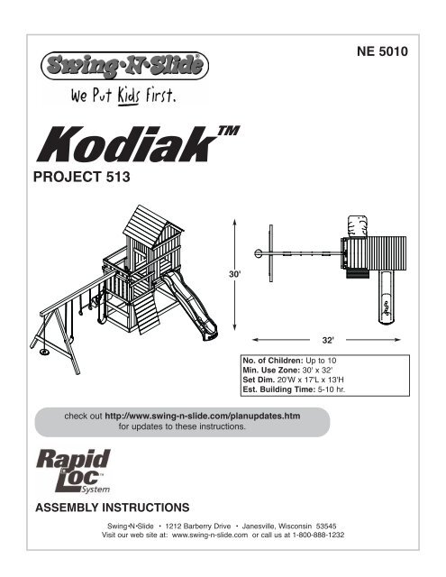
BLACKPROCESSPANTONE "NEWCO RED"RRR<strong>PROJECT</strong> <strong>513</strong>(12) Shelf-Loc (2) Split Beam bracket(8) Step BracketsNote: (4 Left, 4 Right)(12) Wrap-Loc(2) EZ Frame BracketsTHIS PRODUCT ISINTENDED FOR USEBY CHILDREN FROMAGES 2-10 YEARSFor Home / ResidentialUse ONLY1212 Barberry DriveJanesville, WI 535451-800-888-1232www.swing-n-slide.com(4) Climbing Rockswith Hardware(1) Name Plate(1) Multicolor Tarp(2) <strong>Swing</strong> Seatsweight limit: 115 lbs.(4) Safety Handles(4) <strong>Swing</strong> HangersKodiakPlan(1) Instructional DVD(1) T30 Torx® Bit(1) Plan5
<strong>PROJECT</strong> <strong>513</strong><strong>PROJECT</strong> <strong>513</strong> CUTTING LISTBOARD LISTOPTIONAL LADDER(16)-2'' x 4'' x 96''(1)-2'' x 4'' x 120''(17)-5/4'' x 6'' x 120''(14)-5/4'' x 6'' x 144''(6)-4'' x 4'' x 96''(4)-4'' x 4'' x 120''(1)-4'' x 4'' x 144''(1)-4'' x 6'' x 144''OR(2)-2'' x 6'' x 144''(1)-2'' x 4'' x 96''(2)-2'' x 4'' x 120''OPTIONAL ROCK WALL(2)-2'' x 4'' x 96''(2)-5/4'' x 6'' x 144''96''(2) 2'' x 4'' x 96''48''48''(2) 2'' x 4'' x 96''47''48''(1) 2'' x 4'' x 96''47''47''(2) 2'' x 4'' x 96''45''45''(1) 2'' x 4'' x 96''42'' 38-1/2'' 14-3/4''(2) 2'' x 4'' x 96''69-1/2''16''(2) 2'' x 4'' x 96''Two 45˚ Angle Cuts31-1/2'' 31-1/2'' 31-1/2''(2) 2'' x 4'' x 96''52-1/2''30''(2) 2'' x 4'' x 96''52-1/2'' 30'' 30''(1) 2'' x 4'' x 120''41''(2) 5/4'' x 6'' x 120''57''(5) 5/4'' x 6'' x 120''36-3/4''24-1/2''57''(2) 5/4'' x 6'' x 120''96''6
(2) 2'' x 4'' x 96''(1) 2'' x 4'' x 120''52-1/2'' 30'' 30''<strong>PROJECT</strong> <strong>513</strong>41''(2) 5/4'' x 6'' x 120''36-3/4''24-1/2''(5) 5/4'' x 6'' x 120''57''57''96''(2) 5/4'' x 6'' x 120''(8) 5/4'' x 6'' x 120''54''54''48'' 48'' 48''(7) 5/4'' x 6'' x 144''69-1/2'' 45-1/2'' 24-1/2''(2) 5/4'' x 6'' x 144''(3) 5/4'' x 6'' x 144''61''61''(1) 5/4'' x 6'' x 144''72''61''48''36-3/4''33''22-1/2''(1) 5/4'' x 6'' x 144''(6) 4'' x 4'' x 96''(4) 4'' x 4'' x 120''96''120''(1) 4'' x 4'' x 144''48'' 48'' 48''(1) 4'' x 6'' x 144'' or (2) 2'' x 6'' x 144''144''OPTIONAL LADDER47''(1) 2'' x 4'' x 96''48''(2) 2'' x 4'' x 120''47''23-1/4'' 20-1/4'' 20-1/4''OPTIONAL ROCKWALL48''(1) 2'' x 4'' x 96''47''(1) 2'' x 4'' x 96''48''47''36''36''36''36''(2) 5/4'' x 6'' x 144''7
<strong>PROJECT</strong> <strong>513</strong>How to select the correct fastenerUse these 3 pictorial guides to help select the correct fastener(s) for thelumber attachment you are making. Each diagram will highlight the correctnumber of fasteners to use, and where to attach them.5/4'' x 6'' to 4'' x 4''(4) 2-1/2'' screwsApply the 2-1/2" screws to secure the 5/4" boardsto the 4'' x 4'' uprights as shown.Base of unit(1) 2'' lag screwAfter attaching the 2 1/2" screws, apply the center(1) 2" lag screw as shown for additional support.2'' x 4'' to 4'' x 4''(3) 2-1/2'' screwsApply 2 1/2" screws to the 2" x 4" boardswhen attaching to 4"x 4" uprights.5/4'' x 6'' to 2'' x 4''(2) 2'' screwsUse 2" screws when mounting 5/4"boards to 2" x 4" boards.8
<strong>PROJECT</strong> <strong>513</strong>Understanding how the Bracket System WorksShelf-Loc BracketExample of a Shelf-Loc bracket connection.1 2 3 4CORRECT!Wrap-LocWRONG!Brackets''clipped''brackets NOTinterlocked!Example of a Shelf-Loc bracket connection.Look for ''TOP'' stamp onbracket for correct orientation.Introduction to the Bracket system1. ALWAYS Use 2'' lag screws on all brackets.2. Brackets ''clip'' to each other. NEVER positionin a non-interlocking position.TOPTop of bracketWrap-LocGAPBottom of bracket(Hole locations close to bottom)Shelf-LocBrackets Clip Together9
<strong>PROJECT</strong> <strong>513</strong>Fig.1Frame 1 Construction4'' x 4'' x 96''Look for ‘’TOP’’stamp on bracketswhile installing.TOPUse a 2’’ lag screwto hold bracket inplace for later use.(2)2'' lag screwsper bracketGAP onthis side86''47''47''A. Frame 1 ConstructionFrame 11. Measure, assemble and positionbrackets on 4'' x 4'' as shown in(Fig.1).Note: Secure Shelf Lock with (2) LagScrews only at this time.2'' Lag screw10
<strong>PROJECT</strong> <strong>513</strong>•WARNING•Avoid splitting yourlumber by offsettingyour screws at least3/4’’ from edge.Frame 1 Construction(3)2-1/2'' screwsFig.1a2'' x 4'' x 48''2'' x 4'' x 48''50-1/2''Double check to makesure structure is square2'' Lag screw2-1/2'' screw5/4'' x 6'' x 48''Frame 1(1) 2'' lag screw(4) 2-1/2'' screwsA. Frame 1 Construction cont.2. Attach 2'' x 4'' boards and lower 5/4'' board asshown in (Fig. 1a)11
<strong>PROJECT</strong> <strong>513</strong>Frame 2 ConstructionFig.24'' x 4'' x 120''(2)2'' lag screwsper bracketLook for ‘’TOP’’stamp on bracketswhile installing.TOPUse a 2’’ lag screwto hold bracket inplace for later use.GAP onthis side59''B. Frame 2 Construction59''47''1. Measure assemble and position brackets on4'' x 4'' as shown in (Fig.2).Note: Secure Shelf Lock with (2) LagScrews only at this time.47''Frame 22'' Lag screw12
<strong>PROJECT</strong> <strong>513</strong>Frame 2 Construction(3)2-1/2'' screwsFig.2a1-1/2''2'' x 4'' x 45''2'' x 4'' x 45''Double check to makesure structure is square117''96''5/4'' x 6'' x 48''54-1/2''5/4'' x 6'' x 48''Frame 2(1) 2'' lag screw(4) 2-1/2'' screws2-1/2'' screwB. Frame 2 Construction cont.2. Attach upper 2'' x 4'' and lower 5/4''boards as shown in (Fig. 2a)13
<strong>PROJECT</strong> <strong>513</strong>Frame 3 ConstructionFig.34'' x 4'' x 120''Look for ‘’TOP’’stamp on bracketswhile installing.TOPGAP onthis sideUse a 2’’ lag screwto hold bracket inplace for later use.(2)2'' lag screwsper bracket59''47''59''47''Frame 3C. Frame 3 Construction1. Measure assemble and position brackets on4'' x 4'' as shown in (Fig.3).2'' Lag screwNote: Secure Shelf Lock with (2) Lag Screwsonly at this time.14
Frame 3 Construction<strong>PROJECT</strong> <strong>513</strong>Fig.3a2'' x 4'' x 48''(3)2-1/2'' screwsDouble check to makesure structure is square117''2'' x 4'' x 48''62-1/2''(1) 2'' lag screw(4) 2-1/2'' screws5/4'' x 6'' x 48''Frame 3C. Frame 3 Construction cont.2'' Lag screw2-1/2'' screw2. Attach upper 2'' x 4'' and lower 5/4'' boardsas shown in (Fig. 3a)15
<strong>PROJECT</strong> <strong>513</strong>Fig.42'' x 4'' x 47''2'' x 4'' x 47''(3)2-1/2'' screws78''5/4'' x 6'' x 96''5/4'' x 6'' x 96''Frame One(1) 2'' lag screw(4) 2-1/2'' screwsD. Frame Construction1.Install 2’’ x 4’’ and 5/4'' boards as shown above.2'' Lag screw2-1/2'' screw16
<strong>PROJECT</strong> <strong>513</strong>Fig.4aDouble check to makesure structure is square(3)2-1/2'' screwsFrame Two(1) 2'' lag screw(4) 2-1/2'' screws47''D. Frame Construction cont.1. Attach Frame Two as shown above.Frame One2'' Lag screw2-1/2'' screw17
<strong>PROJECT</strong> <strong>513</strong>Tip: Flex brackets to make installation of4'' x 4'' easierFig.5Approx. 1/4''Fig. 5a4'' x 4'' x 96''4'' x 4'' x 96''(4)2'' Lag ScrewsF. Install 4x4s1. Work (2) 4'' x 4'' into brackets asshown in(Fig. 5), (Fig 5a).2. Secure brackets (Fig. 5b).2'' Lag screw x 4Fig.5b18
<strong>PROJECT</strong> <strong>513</strong>Fig.6Double check to makesure structure is square(4) 2'' Lag ScrewsFrame 3(4) 2-1/2'' screws(1) 2'' lag screw(Per joint)Frame 2Frame 1F. Attach Frame 3.1. Attach and secure Frame 3 to rest of unit asshown above.2'' Lag screw2-1/2'' screw19
<strong>PROJECT</strong> <strong>513</strong>Fig.7(2)2-1/2'' screws5/4'' x 6'' x 41''(6) 5/4'' x 6'' x 48''5/4'' x 6'' x 41''2-1/2'' screwG. Install Deck Boards1. Install 5/4'' deck boards to structure as shown (Fig. 7).2. Use two 2-1/2'' screws at each end of deck boards.Note: On End Boards, avoid screwing into Shelf Brackets byplacing screws behind Shelf Bracket location.20
<strong>PROJECT</strong> <strong>513</strong>Bottom ViewFig.8Fig.8b15''(2)2-1/2'' screwsper joint2'' x 4'' x 47''Fig.8a(16)2-1/2'' screws2-1/2'' screwH. Lower Deck Support Board1. Construct support boards as shown in (Fig. 8).2. Secure center of floor boards as shown in (Fig 8a)3. Hold Deck Support Board from below untilsecured in place from above as shown in(Fig. 8b).21
<strong>PROJECT</strong> <strong>513</strong>Fig.8c2'' x 4'' x 47''(3)2-1/2'' screws2'' x 4'' x 47''(3)2-1/2'' screwsI. Install Lower Rail Board2-1/2'' screw1. Install lower 2'' x 4'' rail board as shown in (Fig 8c).Flush with the sides of 4'' x 4'' deck supports.22
<strong>PROJECT</strong> <strong>513</strong>Fig.92'' x 4'' x 96''(3)2-1/2'' screws2'' x 4'' x 96''(3)2-1/2'' screwsK. Install Shelf-Loc brackets1. Install 2x4 boards as shown in (Fig.9).2-1/2'' screw23
<strong>PROJECT</strong> <strong>513</strong>Tip: Flex brackets to make installation of4'' x 4'' easierApprox. 1/4''Fig.10aFig.10bFig.102'' Lag screw x 44'' x 4'' x 48''4'' x 4'' x 48''K. Install 4x4s cont.1. Work (2) 4'' x 4'' into brackets as shown in (Fig. 10a), (Fig 10).2. Secure brackets (Fig. 10b).24
<strong>PROJECT</strong> <strong>513</strong>Fig.11(2)2-1/2'' Deck Screws(2 per joint)(1) 5/4'' x 6'' x 45-1/2''(6) 5/4'' x 6'' x 48''(1) 5/4'' x 6'' x 45-1/2''MAKEBOARDSFLUSH WITH4'' x 4''SUPPORT2-1/2'' screwL. Install Deck Boards1. Install 5/4'' deck boards to structure as shown (Fig. 11).2. Use two 2-1/2'' screws at each end of deck boards. Where shelfbracket blocks screw path, center board and place one screwon either side.25
17-1/4''<strong>PROJECT</strong> <strong>513</strong>Fig.122'' x 4'' x 48''Fig.12aFig.12b(16)2-1/2'' screws2-1/2'' screwM. Install Upper Rail Boards1. Install under deck support as shown in (Fig 12).Flush with the edges of 5/4’’ x 6’’ deck supports.2. Hold Deck Support Board from below until secured inplace from above as shown in (Fig. 12a) and(Fig. 12b).26
<strong>PROJECT</strong> <strong>513</strong>Fig.132'' x 4'' x 52-1/2''(3)2-1/2'' Screws2'' x 4'' x 52-1/2''(5)2-1/2'' Screwsper board(2) 2'' x 4'' x 14-3/4''2'' x 4'' x 52-1/2''(3)2-1/2'' Screws2-1/2'' screwN. Install supports cont.1. Install 2'' x 4'' as shown in (Fig 13)27
<strong>PROJECT</strong> <strong>513</strong>Fig.14Tip: Flex brackets to make installation of4'' x 4'' easierApprox. 1/4''Fig. 154'' x 4'' x 48''(4)2'' Lag ScrewsFig.16O. Install accessory 4x41. Work (1) 4'' x 4'' into brackets as shown in(Fig. 14), (Fig 15).2. Secure brackets (Fig. 16).2'' Lag screw x 428
Optional Laminated Beam<strong>PROJECT</strong> <strong>513</strong>NOTE: Lay the lumber on a flat surfacebefore beginning laminated beam assembly.Fig. 1724"NOTE: Attach one end of the beam with three2-1/2'' screws. Secure boards and attach theother end with three 2-1/2'' screws. This willinsure that your boards will stay alignedthroughout the remainder of the beam assembly.Fig. 17aStagger screws toinsure a sturdybond betweenboardsP. Laminated Beam Instructions1. If 4" x 6" lumber is not available, you maylaminate two 2" x 6" x 144'' pieces of lumbertogether to create the beam.2. Lay the lumber on a flat surface and align all ofthe edges. NOTE: Make sure each piece oflumber is the same length. If it is not, trim board(s).3. From the end of each board, measure and place amark at 24" intervals (Fig. 17).4. Assemble the beam by attaching each endtogether using three 2-1/2'' screws (Fig. 17a).Note: Stagger the screws as shown in (Fig. 17a) toinsure a sturdy bond. Repeat every 24" along theentire length of the beam.When beam is complete,measure, drill holes, and attach beam clamps andnylon bushing swing hangers29
<strong>PROJECT</strong> <strong>513</strong>Fig. 18Q. <strong>Swing</strong> Beam Drill Locations1. Use a 3/8'' drill bit to drill a 3/8’’ hole throughthe beam at each location shown in (Fig. 18)2. Install <strong>Swing</strong> Hangers onto swing beam atlocations shown.Note: <strong>Swing</strong> Hangers must be installed onsame side dimensions were originally marked.TOP VIEW3-1/2''Drill 3/8''Hole<strong>Swing</strong> Beam3-1/2''30
<strong>PROJECT</strong> <strong>513</strong>HammerFig. 193/8'' holeT-nutt-nutBottom Beam Clamp(4) 1-1/4'' screwsQ. <strong>Swing</strong> Beam Drill Locations<strong>Swing</strong> HangerUse Screwdriver to aid in tightening1. Tap t-nut into 3/8’’ hole as shown in (Fig. 19)2. Place a bottom beam clamp over the swing hanger as shown in (Fig. 19)3. Insert the swing hanger into the beam and thread it into the T-nut until it is flush or near flush with the top of theT-nut. A screwdriver may be used to twist the hanger (Fig. 19). Orient swing hanger as shown in (Fig 19).4. Use (4) 1-1/4'' screws to secure beam clamp.5. Check hanger to ensure it does not spin.6. Repeat for both swing hangers.31
<strong>PROJECT</strong> <strong>513</strong>Fig. 20Align the edges of the 4" x 4" legswith the edges of EZ Frame Bracket(8) 2-1/2ʼʼ ScrewsR. A-Frame Assembly1. layout 4'' x 4’’s as shownin (Fig. 20)2. Align EZ Frame Bracket with face of4'' x 4''s.3. Secure EZ Frame Bracket with (8)2-1/2'' screws to 4'' x 4''s makingsure they are flush with each other.4. Secure 5/4'' x 6'' to 4'' x 4''s asshown in (Fig. 21)5. Flip over and add 2nd bracket.Repeat steps 2 and 3.EZ FrameBracketFig. 214" x 4" x 96''4" x 4" x 96''(4)2-1/2'' screws(4)2-1/2'' screws24-1/2"5/4" x 6" x 72"94-1/2"2-1/2'' screw32
<strong>PROJECT</strong> <strong>513</strong>Fig. 22T-nutWasher2-1/2'' screwsCantilever beam5-1/2ʼʼ Hex Bolt2-1/2'' screwS. A-Frame Assembly cont.1. 1. Tap T-nut into 3/8’’ hole as shown in (Fig. 22)Note: If using Laminated <strong>Swing</strong> Beam, make sure T-nut teeth do not fall between seams of 2'' x 6''s.2. Attach A-Frame beam to <strong>Swing</strong> Beam using (2) 5-1/2’’ hex bolts and 4 screws.3. Tighten hex bolt to flush with top of T-nut. Repeat on other bracket.33
<strong>PROJECT</strong> <strong>513</strong>Fig. 23T. A-Frame Assembly cont.1. Position Split-Brackets on 4'' x 4'' x 48'' (Fig 23).2. With the help of others, lift A-Frame and<strong>Swing</strong> Beam Assembly and center onto unit asshown in (Fig. 23)3. Secure as shown in (Fig 24).22-1/4''<strong>Swing</strong> BeamFig. 24<strong>Swing</strong> BeamView from Deck2'' Lag screwx 8 (each bracket)34
<strong>PROJECT</strong> <strong>513</strong>(2)2-1/2'' DeckScrewsper joint5/4'' x 6'' x 57''5/4'' x 6'' x 57''5/4'' x 6'' x24-1/2''5/4'' x 6'' x24-1/2''5/4'' x 6'' x24-1/2''5/4'' x 6'' x24-1/2''2'' Deck Screws(2 per joint)Fig.252'' Deck Screws(2 per joint)5/4'' x 6'' x 57''5/4'' x 6'' x 57''1-1/2ʼʼ Gap(2) 2'' x 4’’ x 30''1-1/2ʼʼ GapFig.25aV. Barrier Boards1. Install 2x4 and 5/4'' barrier boardsevenly spaced in the opening.5/4'' x 6’’ x 69-1/2''2'' x 4’’ x 69-1/2''2'' x 4’’ x 31-1/2''2'' x 4’’ x 31-1/2''2'' x 4’’ x 31-1/2''2'' x 4’’ x 31-1/2''2'' x 4’’ x 31-1/2''2'' x 4’’ x 31-1/2''33-1/2ʼʼBottom ofBoardTo Deck2'' x 4’’ x 69-1/2''5/4'' x 6’’ x 69-1/2''(1) 5/4'' x 6’’ x 22-1/2''2'' Deck Screws(2 per joint)Make Bottom of Boards FlushWith Bottom of Deck Support2'' screw35
<strong>PROJECT</strong> <strong>513</strong>5/4'' x 6'' x 61''5/4'' x 6'' x 61''5/4'' x 6'' x 61''5/4'' x 6'' x 61''5/4'' x 6'' x 61''5/4'' x 6'' x 61''5/4'' x 6'' x 61''2'' Deck Screws(2 per joint)Fig.262'' Deck Screws(2 per joint)5/4'' x 6'' x 48''5/4'' x 6'' x 48''5/4'' x 6'' x 48''5/4'' x 6'' x 48''5/4'' x 6'' x 48''Fig.26a2'' Deck Screws(2 per joint)5/4'' x 6'' x 57''5/4'' x 6'' x 57''5/4'' x 6'' x 57''5/4'' x 6'' x 36-3/4''5/4'' x 6'' x 36-3/4''5/4'' x 6'' x 57''5/4'' x 6'' x 57''5/4'' x 6'' x 57''V. Barrier Boards cont.1. Install 5/4'' barrier boards evenlyspaced in the opening.1-1/2ʼʼ Gap2'' x 4’’ x 30''2'' x 4’’ x 30''1-1/2ʼʼ Gap2-1/2'' Deck Screws(2 per joint on 2'' x 4''s)2'' screw36
<strong>PROJECT</strong> <strong>513</strong>Fig.27x22'' x 4'' x 16''Fig.27a2'' x 4'' x 38-1/2''(3)2-1/2'' Deck Screws(per joint)(4) 5/4'' x 6'' x 54''(2)2-1/2'' Deck Screws(per joint)1-1/2'' Overhang2'' x 4'' x 42''W. Roof Construction.1. Constuct Wood Roof Frame as shown in(Fig 27) and (Fig. 27a).1-1/2'' Overhang48''Fig.28(3)2-1/2'' Deck Screws(per joint)W. Roof Construction.2-1/2'' screw2. Attach wood Roof as shown in (Fig 28)37
<strong>PROJECT</strong> <strong>513</strong>Fig.292-1/2'' Deck Screws(2 per joint)(6) 5/4'' x 6'' x 54''Fig.30(6) 5/4'' x 6'' x 54''2-1/2'' Deck Screws(2 per joint)X Roof Construction cont.3. Install 5/4'' x 6''s as shown in (Fig 29) and(Fig. 30).2-1/2'' screw38
<strong>PROJECT</strong> <strong>513</strong>Fig.30a2'' Deck Screws(2 per joint)(1) 5/4'' x 6'' x 33'' (1) 5/4'' x 6'' x 36-3/4''Fig.30b2'' Deck Screws(2 per joint)X Support Boards cont.1. Install 5/4'' x 6'' Roof Supports as shown in(Fig 30a) and (Fig 30b).2'' screw39
<strong>PROJECT</strong> <strong>513</strong>SIDE OPENING OPTION 1Fig. 312'' x 4'' x 48''(Left Side)(Front)2'' x 4'' x 48''(Right Side)2'' x 4'' x 23-1/4''2'' x 4'' x 23-1/4''(2) 2-1/2’’ Screws2'' x 4'' x 23-1/4''(2) 2-1/2’’ Screws2'' x 4'' x 20-1/4''(2) 2-1/2’’ Screws(2) 2-1/2’’ Screws43-5/8’’42-1/8’’2'' x 4'' x 20-1/4''43-5/8’’40-3/8’’ 40-3/8’’42-1/8’’29-1/2’’(2) 2-1/2’’ Screws27-7/8’’27-7/8’’(2) 2-1/2’’ Screws29-1/2’’17’’(2) 2-1/2’’ Screws15-1/4’’2'' x 4'' x 20-1/4''15-1/4’’17’’(2) 2-1/2’’ Screws4-3/8’’ 2-3/4’’2'' x 4'' x 20-1/4''2-3/4’’ 4-3/8’’40
Top Corner of 2'' x 4''SIDE OPENING OPTION 1<strong>PROJECT</strong> <strong>513</strong>EXAMPLE OF LADDER RUNG INSTALLATION2-1/2''2- 3/4''From BottomSTEP BRACKET(6)1-1/4''screws• BOTTOM OF LADDER RAIL •Bottom Corner of 2'' x 4''Fig. 32O. Ladder Assembly.1. On ladder rails, mark all measurement locations foreach side with a pencil. Draw an angle lineconnecting measurements for each ladder rungalignment. (Fig. 31)2. Align top of step bracket with line and screw inplace. Install a ladder rung at each of the fourlocations. (Fig. 31) and (Fig. 32). Repeat on otherladder rail.3. Attach 2'' x 4'' x 23-1/4'' to siderails using(2) 2-1/2'' screws per side.4. Secure ladder to unit. (Fig. 33), and (Fig. 34)Note: The top step should be 11" below the deckand all steps should be level.5. Screw (2) 2-1/2" screws into the ends of each ladderrung through the left and right side rails. (Fig. 34)(6) 1-1/4'' screws2-1/2'' screw(2)2-1/2'' screwseach side2'' x 4'' x 23-1/4''(3)2-1/2'' screwseach side(3)2-1/2'' screwsunderneath2'' x 4'' x 47''(2)2-1/2'' screwseach side2'' x 4'' x 47''10-3/4''Fig. 33(2)2-1/2'' screwsper jointFig. 3441
<strong>PROJECT</strong> <strong>513</strong>Fig. 35(9)2-1/2'' Deck Screws(3 Per joint)5/4'' x 6'' x 48''19''2-1/2'' screwZ1. Install Protective Barrier Board1. Secure protective 5/4'' barrier board as shown in (Fig 35).42
BLACKRFig. 36<strong>PROJECT</strong> <strong>513</strong>Fig. 371 - 3/4Panheadscrewwasher11"Deck SurfaceINSTALL PLAY HANDLESHERE1'' Truss ScrewUse truss head screws toto secure slide to deck.<strong>Slide</strong>/Safety HandleInstallation.1. Mount safety handles in the ladderopening approximately 11'' above thedeck surface (Fig. 36).2. Install <strong>Slide</strong> as shown in (Fig. 37)Important:Do not use hardware providedwith slide. Use Truss head screwsincluded with Kit.THIS PRODUCT ISINTENDED FOR USEBY CHILDREN FROMAGES 2-10 YEARSFor Home / ResidentialUse ONLY1212 Barberry DriveJanesville, WI 535451-800-888-1232wwwSecure your product ID tag onto easyto read location of any 4'' x 4''.swing-n-slide.comusing (2) 2'' screws43
<strong>PROJECT</strong> <strong>513</strong>Anchor-It (Sold Seperately)Fig. 38Flat Washermetal strap1-1/2"lag boltAnchor-ItstakeS. Anchor-It Installation (optional).Instructions for Anchoring <strong>Swing</strong>•N•<strong>Slide</strong> Activity Centers1. Determine the final location of your activity center.2. Place the Anchor-It stakes adjacent to the base and near the corners of your activity center (at the bottom of the legson swing sets) and twist the auger-style stakes into the ground until only the loop is exposed.3. Place the metal strap through the loop of the Anchor-It stake and secure it to the unit with a lag screw and washeras illustrated to the right. Note: Attach the strap to the unit with as little play as possible using whatever holes in thestrap that work best.44
2'' x 4'' x 47''2'' x 4'' x 47''2'' x 4'' x 48''2'' x 4'' x 48''SIDE OPENING OPTION 2Fig. 39<strong>PROJECT</strong> <strong>513</strong>Fig. 40(8) 5/4'' x 6'' x 36''9-1/2''9-1/2''2-1/2'' Deck Screws(2 Per joint)6''(2)2-1/2'' screws(Per joint)6''2-1/2'' screwFig. 40aNOTE:4' Climbing Rock Wall will requireMin. 8 Climbing Rocks(2) Bags of NE 4543S Climbing Rocks.2-1/2'' Deck Screws(2 Per joint)Climbing Wall Lumber Cut List.(1) 2x4x96 ------ (2) 2x4x47(1) 2x4x96 ------ (2) 2x4x48(2) 5/4x6x144 - (4) 5/4x6x361. Assemble and install Climbing Wall Frame as shownin (Fig. 39), (Fig. 40).2. Attach (8) 5/4'' x6'' boards to (2) 2'' x 4'' boardsand install on unit as shown in (Fig. 40a).3. Secure Rock Wall to unit using (3) 2-1/2'' screwsper side.Note: Make sure the 2'' x 4'' supports do notinterfere with the mounting of the climbingrocks.45
<strong>PROJECT</strong> <strong>513</strong>Climbing RockFig. 41(2)"T" nuts3/8" Holes(2) 2'' Hex Head BoltsHold (rock)(1) Loc Washer per bolt(1) Flat Washer per boltClimbing Rock Installation1. Mark locations of Climbing Rocks on the Climbing Wall in a pattern thatwill easily allow your child to climb to the deck. Make sure the bolt holelocations are clear of wall supports before drilling.2.Drill holes through the wall at the desired locations using a 3/8" drill bit.Install Climbing Rocks as shown in (Fig. 41).3. Make sure the Climbing Wall and Climbing Rock connections are securebefore allowing any children to play on the Climbing Wall.46
47<strong>PROJECT</strong> <strong>513</strong>
Questions???...Call our Customer Service Departmentat 1-800-888-1232© PlayCore Inc. 2007 Printed In USA LA 5821