Assembly Instructions - Swing-N-Slide
Assembly Instructions - Swing-N-Slide
Assembly Instructions - Swing-N-Slide
- No tags were found...

You also want an ePaper? Increase the reach of your titles
YUMPU automatically turns print PDFs into web optimized ePapers that Google loves.
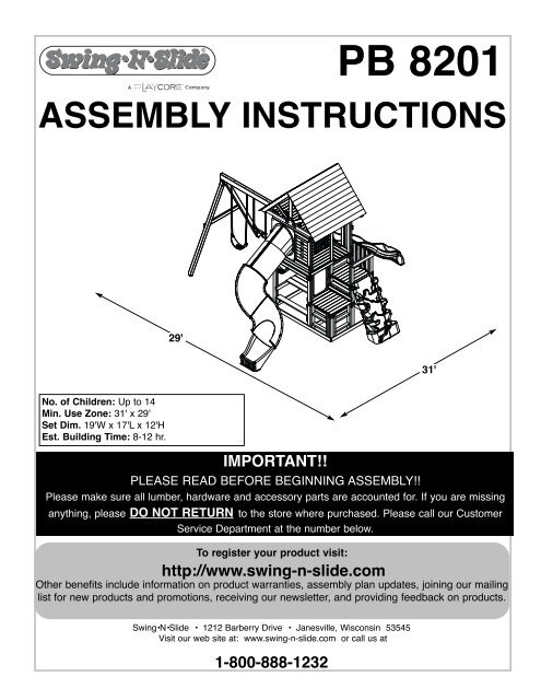
PB 8201ASSEMBly INSTRUCTIONS29'31'No. of Children: Up to 14Min. Use Zone: 31' x 29'Set Dim. 19'W x 17'L x 12'HEst. Building Time: 8-12 hr.IMPORTANT!!PLEASE READ BEFORE BEGINNING ASSEMBLY!!Please make sure all lumber, hardware and accessory parts are accounted for. If you are missinganything, please DO NOT RETURN to the store where purchased. Please call our CustomerService Department at the number below.To register your product visit:http://www.swing-n-slide.comOther benefits include information on product warranties, assembly plan updates, joining our mailinglist for new products and promotions, receiving our newsletter, and providing feedback on products.<strong>Swing</strong>•N•<strong>Slide</strong> • 1212 Barberry Drive • Janesville, Wisconsin 53545Visit our web site at: www.swing-n-slide.com or call us at1-800-888-1232
Safety Checklist for <strong>Swing</strong>-N-<strong>Slide</strong> Play Sets and AccessoriesObserving the following statements and warnings reduces the likelihood of serious or fatal injuryInstallation Safety – Have You:Consulted the assembly instructions supplied with your particular model?Noted this accessory is to be used only on <strong>Swing</strong>•N•<strong>Slide</strong> approved designs? (Do not alter its design or add/remove components.)Made sure all hardware is tightened securely? (Supplied bolt covers must also be fastened securely.)Using a hacksaw, cut off all protruding threaded ends of bolts and other fasteners and remove any sharp edges witha metal file as needed, and coated fastener ends with lead free paint?Placed the equipment on level ground, not less than six feet (1.8 meters) from any structure or obstruction such as a fence, garage,house, overhanging branches, laundry lines, or electrical wires?Made sure home playground equipment is not installed over concrete, asphalt, packed earth or any other hard surface? (A fall ontoa hard surface can result in serious injury to the equipment user.)Verified that suspended climbing ropes, chain,or cable are secured at both ends?Consulted in assembly instructions of your particular model for minimum use zones?Used a water sealant on your play set to protect the wood and prevent cracking and warping?Followed all anchoring and shock absorbing surfacing requirements on the back of this sheet as they apply?Made sure not to allow children to use equipment until it is properly installed?Made sure to adjust all swings so there is a minimum 8'' clearance between the swing and the ground surface?Operating Safety – Have You:Determined that on-site adult supervision is provided for children of all ages?Warned children the following before allowing them to use the equipment?Not to walk close to, in front of, behind or between moving items.Not to twist swing or any other accessory chains or ropes or loop them over the top support bar since this will reduce thestrength of chain or rope.Not to swing empty seats or other accessories.Not to slide down swing chains.Be sure to sit in the center of the swing seat and other accessories with full weight on the seat.Not to attach items to the playground equipment that are not specifically designed for use with the equipment such as but notlimited to, jump ropes, clotheslines, pet leashes, cables and chain. They may cause a strangulation hazard.Not to climb or walk on the top of swing beams, railings or roof.Not to use equipment in a manner other than intended.Not to get off equipment while it is in motion.Not to climb on the equipment when it is wet.Be sure to go down slides feet first.Determined that only one child per planned occupant seat should be allowed on this set at one time.Determined children must be dressed appropriately for play. Avoid hooded jackets, bicycle helmets, clothing with draw strings andloose fitting clothes which could become entangled or snagged on equipment.Determined that suspended climbing ropes, chain, or cable cannot be looped back upon itself.Made certain the slide is placed so that is is not in direct sunlight.Safety Maintenance – At the beginning of every season and twice monthly thereafter:Rake and check depth of loose fill protective surfacing material to prevent compaction and maintain appropriate depth. Replace asnecessary.Check all nuts, bolts and C-Links during the usage season for tightness and tighten as required. (It isparticularly important that this procedure be followed at the beginning of each season.)To prevent the deterioration of materials, remove plastic swing seats and other plastic accessories when outdoors temp dips down toor below 32° F and take indoors.Oil all metallic moving parts monthly during usage period.Check all hardware and equipment for sharp edges during usage season. (Replace when necessary. It is especiallyimportant to do this at the beginning of each new season.)Check swing seats, chains, ropes and cables monthly during usage season for evidence of deterioration. Severe rusting or excessive wear,especially near the top swing hanger or at the seat connection are evidence of chain deterioration. Cracks in the protective plastic sleeveor seat itself are also signs of deterioration. If any of these conditions exist, call 1-800-888-1232 to order replacement accessories.Sand rusted metal parts and repaint using non-lead based paint.Check all wood members for deterioration and splinters. Sand down splinters and replace deteriorating wood members.Disposal <strong>Instructions</strong>When the equipment is taken out of service, it must be disassembled and disposed of in such a way that no unreasonable hazardswill exist at the time the set is discarded.Important! Additional Safety <strong>Instructions</strong> for all <strong>Swing</strong>-N-<strong>Slide</strong> Playground Equipment.Save this instruction sheet in the event the manufacturer needs to be contacted.2
This product is intended for single family home/residential use only and not intended for use in any public setting.Placement in any public setting constitutes a misuse of this product.IMPORTANT!ADDITIONAL REQUIRED SAFETY INSTALLATION INSTRUCTIONSAccording to ASTM requirements, all kits must be anchored to the ground and, if the unit has a climbing rope, the rope end must be anchored to the ground. If soil conditionspermit stakes to be pulled out easily, cementing into ground is necessary.• To anchor the unit to the ground, Follow the instructions included in this plan for applying Anchor-It devices to your unit, or use 2" x 4" x 18" (45mm x 95mm x 457mm) pressuretreatedstakes. Pound stakes into ground at least 12" (305mm) at all inside corners of the posts (including A-frame legs and climbing unit posts). Attach with four (4) 16D (3-1/2")galvanized nails per stake into each tower and/or A-frame upright.• If the unit has a climbing rope, anchor the rope end.• Once the unit is completely assembled and before children are allowed to play on it, proper shock-absorbing surfacing material must be installed. This may be accomplished byusing loose-fill materials at a sufficient depth. The Consumer Product Safety Commission “Handbook for Public Playground Safety” lists the following materials and requireddepths that are sufficient for home/residential application. For fall height protection up to 9 ft. (2.742m) [recommended for <strong>Swing</strong>•N•<strong>Slide</strong> kits]:LOOSE FILL MATERIALREQUIRED (UNCOMPRESSED) DEPTH 1 in. (mm)Wood Mulch9" (229mm)Double Shredded Bark Mulch9" (229mm)Uniform Wood Chips12" (305mm)Fine Sand12" (305mm)Fine Gravel12" (305mm)These depths were derived from the CPSC Handbook. <strong>Swing</strong>•N•<strong>Slide</strong> has not done independent tests to determine these required depths.When properly installed, shock absorbing material will completely cover the horizontal baseboards on climbing units. This protective surfacing must extend a minimum of 6 ft.(1.828m) in all directions from the perimeter of the equipment or from the outermost edges of any component. For example, a slide extending beyond the platform must haveprotective surfacing at least 6 ft. (1.828mm) out from both sides as well as the end. For swings, the protective surface must extend at least 14 ft. (6m) out from both the back andfront of the swing when the swing is in its rest position.For further information on playground safety, the Consumer Product Safety Commission(CPSC) publishes the Outdoor Home Playground Safety Handbook which can be downloaded for freefrom www.cpsc.gov. An additional resource is the American Society of Testing and Materials (ASTM)Standard Consumer Safety Performance Specification for Home Playground Equipment (ASTM F1148)which can be purchased and downloaded from www.astm.org.<strong>Swing</strong>-N-<strong>Slide</strong>® MANUFACTURERS LIMITED WARRANTY<strong>Swing</strong>-N-<strong>Slide</strong>® takes great pride in the quality and durability of our products. Our Manufacturer’s Limited Warranty provides confidence and demonstrates our commitmentto providing quality residential playground products.MANUFACTURER’S LIFETIME LIMITED WARRANTY<strong>Swing</strong>-N-<strong>Slide</strong>® warrants its thermoformed slides and climbing mountains to be free from defects in workmanship and materials, under normal use and conditions, for thelifetime of the product.MANUFACTURER’S 5 YEAR LIMITED WARRANTY<strong>Swing</strong>-N-<strong>Slide</strong>® warrants its Custom Ready-to-Build Play Set kits and accessories to be free from defects in workmanship and materials, under normal use and conditions,for a period of 5 years.MANUFACTURER’S 5 YEAR LIMITED WARRANTY<strong>Swing</strong>-N-<strong>Slide</strong>® warrants its No-Cut and Wood Complete Ready-to-Assemble Play Set kits against wood rot and termite damage, and to be free from defects inworkmanship and materials, under normal use and conditions, for a period of 5 years for structural wood components.Cosmetic defects that do not affect the structural integrity of the product, or natural defects of wood such as warping, splitting, checking, twisting, shrinkage, swelling orany other physical properties of wood that do not present a safety hazard, are not covered by this warranty.MANUFACTURER’S ONE YEAR WARRANTY<strong>Swing</strong>-N-<strong>Slide</strong>® warrants its canopy roofs and/or tarps, and Timber GLOVE lumber wrap to be free from defects in workmanship and materials, under normal use andconditions, for a period of one year.<strong>Swing</strong>-N-<strong>Slide</strong>® will repair, or at its discretion, replace any part within the stated warranty period which is defective in workmanship or materials. This decision is subjectto verification of the defect upon delivery of the defective part to <strong>Swing</strong>-N-<strong>Slide</strong>® at 1212 Barberry Drive, Janesville, Wisconsin, 53545. Any part(s) returned to <strong>Swing</strong>-N-<strong>Slide</strong>® must have prior approved Return Authorization Number and proof of purchase, including the date of purchase. This warranty is valid only if the product is used forthe purpose for which it was designed and installed at a residential, single family dwelling. This warranty is void if the product is put to commercial or institutional use. Thiswarranty does not cover (a) products which have been damaged by acts of Nature, negligence, misuse, or accident, or which have been modified or repaired byunauthorized persons; (b) the cost of labor; or the cost of shipping the product, any part, or any replacement product or part.<strong>Swing</strong>-N-<strong>Slide</strong>® DISCLAIMS ALL OTHER REPRESENTATIONS AND WARRANTIES OF ANY KIND, EXPRESS, IMPLIED, STATUTORY OR OTHERWISE, INCLUDING THEIMPLIED WARRANTIES OF MERCHANTIBILITY AND FITNESS FOR A PARTICULAR PURPOSE. <strong>Swing</strong>-N-<strong>Slide</strong>® WILL NOT BE LIABLE FOR ANY INCIDENTAL ORCONSEQUENTIAL DAMAGES. This warranty is non-transferable and does not extend to the owners of the product subsequent to the original purchaser. Some states do notallow limitations on implied warranties or exclusion of incidental or consequential damages, so these restrictions may not be applicable to you. This warranty gives youspecific legal rights. You may also have other rights, which vary from state to state.This warranty also does not apply to:• Structures not erected, maintained or inspected in conformance with <strong>Swing</strong>-N-<strong>Slide</strong>® installation plans• Structures that have had parts added or substituted not in conformance with <strong>Swing</strong>-N-<strong>Slide</strong>® installation plans• Parts that have been modified, altered or misused• Parts that have not been used as designed or intended• Damage due to acts of Nature, vandalism, abnormal use or abuse as determined by <strong>Swing</strong>-N-<strong>Slide</strong>®3
TOOLS REQUIRED • HERRAMIENTAS REQUERIDAS • OUTILS REQUISTOOLS REQUIREDElECTRIC DRIll 1/2" SOCKET & WRENCH HAMMERTAPE MEASURESAFETy GlASSES& DUST MASKPHIllIPS BITCARPENTER'S SQUARE(2) 1/2'' Panhead Screw(48) 2'' Wood Screw(24) 3/4'' Truss Head Screw(734) 2-1/2'' Wood Screw(16) 5/16''Flat Washer(16) 8mmWasher(4) 1''Truss Head Screw(66) 1-1/4'' Lag Screw(16) Loc-Washer(4) 1-3/4' 'Pan Head Screw(24) 3/4'' Wood Screw(80) 2'' Lag Screw(16) 1/4'' x 1-1/2'' Hex Head Bolt(2) 5/16 T-Nut(4) 1/4''Flat Washer(328) 1-1/4'' Wood Screw(4) 1-1/2'' Lag Bolt(88) 1-1/2'' Wood Screw(4) Rope Staple(2) 5-1/2'' Hex Head Bolt4
<strong>Assembly</strong> <strong>Instructions</strong>Board list Cont.(1) 5/4'' x 4'' x 36''(7) 5/4'' x 6'' x 41''(22) 5/4'' x 6'' x 66'' Roof ShingleNOM INAL M ATERIAL SIZELISTED SIZETRUE SIZEEnglish(*) Metric(Cm) English(*) Metric(Cm)1x4 2.5x7.6 3/4x3-1/2 1.9x91x6 2.5x15.3 3/4x5-1/2 1.9x145/4x4 3.2x10.2 1x3-1/2 2.5x95/4x6 3.2x15.3 1x5-1/2 2.5x142x2 5x5 1-1/2x1-1/2 3.8x3.82x3 5x7.6 1-1/2x2-1/2 3.8x6.42x4 5x10 1-1/2x3-1/2 3.8x92x6 5x15.3 1-1/2x5-1/2 3.8x143x3 7.6x7.6 3 x3 7.6x7.64x4 10x10 3-1/2x3-1/2 9x9(*) Estim ated Sizing Due to Cutting Process(2) 3'' x 3-1/2'' x 94''(1) 3'' x 5-1/2'' x 94'' <strong>Swing</strong> Beam(1) 4'' x 4'' x 54''( TUNNEl TWISTER TUBE SlIDElUMBER(1) 2'' x 4'' x 7''(2) 2'' x 4'' x 8-1/4''(3) 2'' x 4'' x 18''How to select the correct fastenerUse these 2 pictorial guides to help select the correct fastener(s) for thelumber attachment you are making. Each diagram will highlight the correctnumber of fasteners to use, and where to attach them.1'' x 4'' to 3'' x 3''(1) 4'' x 4'' x 66''((3) 2-1/2'' screwsApply 2-1/2" screws to the 1''x4'' boardswhen attaching to 3''x3'' uprights.1'' x 4'' to 1'' x 4''(2) 1-1/4'' screwsUse 1-1/4'' screws when mounting 1'' x 4''boards to 1''x4'' boards.8
<strong>Assembly</strong> <strong>Instructions</strong>Look for ‘’TOP’’stamp on bracketswhile installing.TOPGAP onthis sideBottom of bracket(Hole locations close to bottom)Fig. 1x42'' x 3'' x 54'' 2'' x 3'' x 54''(2)2-1/2''WoodScrewsApprox.Every 12''2'' x 3'' x 66'' 2'' x 3'' x 42''(2)1-1/4''Lag ScrewPer BracketJointFig. 1a47-1/4''29-1/4''FRAME 1DO NOT USE lAGSCREWS HEREUse Lag Screws Only WhereBrackets Attach(2)1-1/4''Lag ScrewPer BracketJoint59-1/4''(2)2'' Lag Screwsper joint59-1/4''Fig. 1b(2)2''Lag ScrewPerBracketJoint(2)1-1/4''Lag ScrewPer BracketJointDO NOT USE lAGSCREWS HEREUse Lag Screws Only WhereBrackets Attach84-1/2''(2)1-1/4'' Lag Screwsper jointFRAME 21-1/4'' lag Screw2'' lag ScrewUpright <strong>Assembly</strong>1. Laminate (4) Uprights as shown in (Fig. 1).2. Install bracket sets on (4) finished uprights as shown in (Fig. 1a) and(Fig. 1b).2-1/2'' Wood Screw9
<strong>Assembly</strong> <strong>Instructions</strong>Tip: Flex brackets to make installation of2'' x 4'' easier(2)1-1/4'' LagApprox. 1/4''Double checkto makesure structureis square(3)2'' LagNOTE: Upper screws are (2) 1-1/4''Lag Screws, Lower screws are (3) 2''Lag Screws.Fig. 21'' x 4'' x 54''(3)2-1/2'' screwsFig. 2a1'' x 4'' x 54''(3)2-1/2'' screws(3)2-1/2'' screws(3)2-1/2'' screws2'' x 4'' x 54''2'' x 4'' x 54''(2) 1-1/4'' lag screwsand(3) 2'' lag screwsper bracket(2) 1-1/4'' lag screwsand(3) 2'' lag screwsper bracket(3)2-1/2'' screws1'' x 4'' x 54''FRAME 1(3)2-1/2'' screws(3)2-1/2'' screws1'' x 4'' x 54''FRAME 2(3)2-1/2'' screws1-1/4'' lag Screw2'' lag ScrewFrame <strong>Assembly</strong>1. Assemble Frame 1 as shown in (Fig. 2).2. Assemble Frame 2 as shown in (Fig. 2a).2-1/2'' Wood Screw10
<strong>Assembly</strong> <strong>Instructions</strong>(2)1-1/4'' LagFig. 3(3)2-1/2'' screws(3)2-1/2'' screws2'' x 4'' x 47-1/2''(3)2'' LagNOTE: Upper screws are (2) 1-1/4''Lag Screws, Lower screws are (3) 2''Lag Screws.2'' x 4'' x 47-1/2''2'' x 4'' x 47-1/2''101-3/8''Double checkto makesure structureis square2'' x 4'' x 47-1/2''88''(2) 1-1/4'' lag screwsand(3) 2'' lag screwsper bracket(3)2-1/2'' screws1'' x 4'' x 74-1/2''FRAME 21'' x 4'' x 74-1/2''(3)2-1/2'' screws1-1/4'' lag ScrewFrame <strong>Assembly</strong> cont.1. Attach support boards to Frame 2 as shown in (Fig. 3).2'' lag Screw2-1/2'' Wood Screw11
<strong>Assembly</strong> <strong>Instructions</strong>(2)1-1/4'' LagFig. 4(3)2'' LagNOTE: Upper screws are (2) 1-1/4''Lag Screws, Lower screws are (3) 2''Lag Screws.(3)2-1/2'' screws(3)2-1/2'' screwsDouble checkto makesure structureis square(2) 1-1/4'' lag screwsand(3) 2'' lag screwsper bracketFRAME 247-1/2''(3)2-1/2'' screwsFRAME 1(3)2-1/2'' screws1-1/4'' lag ScrewFrame <strong>Assembly</strong> Cont.1. Attach Frame 1 to Frame 2 as shown in (Fig. 4).2'' lag Screw2-1/2'' Wood Screw12
<strong>Assembly</strong> <strong>Instructions</strong>Fig. 83/8’’ Hole LocationsPRE-DRILLED80''DRILL3-1/4''PRE-DRILLED<strong>Swing</strong> Beam <strong>Assembly</strong>1. Identify your 3'' x 5-1/2'' x 94'' <strong>Swing</strong> Beam bylocating the board with the holes predrilled asshown in (Fig. 8).2. Drill (6) 3/8'' holes as noted by “Drill” in(Fig. 8).PRE-DRILLED3-1/4''59-1/2''DRILLTOP VIEWPRE-DRILLED3-1/4''49-1/2''DRILL3''94''39''DRILL3-1/4''PRE-DRILLED28''3-1/4''DRILLPRE-DRILLEDDrill 3/8''Hole<strong>Swing</strong> BeamPRE-DRILLED3-1/4''7-1/2''DRILL3'' 3-1/2''16
<strong>Assembly</strong> <strong>Instructions</strong>Fig. 96-1/2'' Carriage BoltsFor <strong>Swing</strong> Hangers(4)1-1/4'' Screwsper Beam ClampBeam ClampWasherLoc-Nut1-1/4'' Screw<strong>Swing</strong> Beam Hardware1. Center beam clamps over the holes on the Same Side of the <strong>Swing</strong> Beam You Drilled Your Holesand attach using four 1-1/4" screws per beam clamp as shown in (Fig. 9).2. Insert carriage bolt through the beam clamp and beam. Tapping the bolts through the beam with ahammer may be required.NOTE: The square base of the carriage bolt must seat into the square hole of the beam clamp.3. Place swing hanger over the protruding bolts on the underside of the beam and attach using two washersand loc nuts per swing hanger. Tighten loc nuts securely.4. Place accessory chains over the quick link and tighten with wrench until secure.Note: When attaching Quick Link, make certain threads are pointing up. This will help keep the Quick Linkfrom loosening over time.5. Repeat for all four hangers.17
<strong>Assembly</strong> <strong>Instructions</strong>Fig. 103-1/2'' FACE(8) 2-1/2’’ ScrewsA-Frame <strong>Assembly</strong>Align the edges of the 3" x 3-1/2" legswith the edges of EZ Frame Bracket3-1/2'' FACE3'' FACE1. layout 3'' x 3-1/2’’s and 2'' x 4''as shown in (Fig. 10).2. Align EZ Frame Bracket with face of3'' x 3-1/2''s.3. Secure EZ Frame Bracket with (8)2-1/2'' screws to 3'' x 3-1/2''smaking sure they are flush with eachother.4. Secure 2'' x 4'' to 3'' x 3-1/2''s asshown in (Fig. 10a).5. Flip over and add 2nd bracket.Repeat steps 2 and 3.Fig. 10aEZ Frame Bracket3" x 3-1/2" x 94''3" x 3-1/2" x 94''(4)2-1/2'' screws(4)2-1/2'' screws2" x 4" x 47-1/2"3-1/2'' FACE46-3/4"93"2-1/2'' screw18
<strong>Assembly</strong> <strong>Instructions</strong>T-nutFig. 11Washer2-1/2'' screwsHex Bolt5-1/2'' Hex Bolt2-1/2'' screwA-Frame <strong>Assembly</strong> cont.1. Align EZ-Frame Bracket with carriage bolts on <strong>Swing</strong> Beam as shown in (Fig. 11).2. Attach A-Frame beam to <strong>Swing</strong> Beam using (2) washers and (2) Loc-Nuts and 2 screws as shown in (Fig. 11).3. Tighten Loc-Nut. Repeat on other bracket.Note: Examine all hardware after the loc-nuts are fully tightened. If more than two threads are exposed, cut theexcess bolt off with a hacksaw or other suitable cutting tool.19
25-1/2''<strong>Assembly</strong> <strong>Instructions</strong><strong>Swing</strong> Beam AttachFig. 121. Position Split-Beam Brackets on 4'' x 4'' x 47-1/2''(Fig 12).2. With the help of others, lift A-Frame and<strong>Swing</strong> Beam <strong>Assembly</strong> and center onto unit asshown in (Fig. 12).3. Secure as shown in (Fig 12a).<strong>Swing</strong> BeamFig. 12a<strong>Swing</strong> BeamView from Deck2'' Lag screwx 8 (each bracket)20
<strong>Assembly</strong> <strong>Instructions</strong>Fig. 13(2) 2'' x 3'' x 73''x2(2)2-1/2''WoodScrewsSpacedEvenly(2) 2'' x 3'' x 59''(2) 2'' x 3'' x 29-1/4''DO NOT USE lAGSCREWS HEREUse Lag Screws Only WhereBrackets AttachFig. 13a73'' Upright73'' Upright(2)1-1/4'' Lag Screwsper joint59'' Upright(2)1-1/4''Lag ScrewPer BracketJoint29-1/4'' UprightFLUSH47-1/4''47-1/4''47-1/4''29-1/4''29-1/4''Lower Deck Upright <strong>Assembly</strong>1-1/4'' lag Screw1. Laminate the Uprights for the Lower Decks as shown in (Fig. 13).2. Install bracket assemblies as shown in (Fig, 13a).2-1/2'' Wood Screw21
<strong>Assembly</strong> <strong>Instructions</strong>Fig. 142'' x 4'' x 27''(3)2-1/2'' screwsper joint(2)1-1/4'' Lag(3)2'' Lag73'' Upright73'' UprightFLUSHFig. 14aNOTE: Upper screws are (2) 1-1/4''Lag Screws, Lower screws are (3) 2''Lag Screws.(3)2-1/2'' screwsper joint1'' x 4'' x 54''FRAME 32'' x 4'' x 30''2'' x 4'' x 30''(2) 1-1/4'' lag screwsand(3) 2'' lag screwsper bracketDouble checkto makesure structureis squareFRAME 31-1/4'' lag Screw2'' lag ScrewLower Deck Frame <strong>Assembly</strong>1. Assemble the lower Deck <strong>Assembly</strong> as shown in (Fig. 14).2. Attach Deck Support Boards as shown in (Fig. 14a).2-1/2'' Wood Screw22
<strong>Assembly</strong> <strong>Instructions</strong>Fig. 15(3)2-1/2'' screwsFrom BackSide27''59'' Upright(3)2-1/2'' screwsFRAME 1Lower Deck Frame <strong>Assembly</strong> Cont.1. Install Lower Deck Support as shown in (Fig. 15).2-1/2'' Wood Screw23
<strong>Assembly</strong> <strong>Instructions</strong>(2)1-1/4'' LagFig. 16(3)2'' LagNOTE: Upper screws are (2) 1-1/4''Lag Screws, Lower screws are (3) 2''Lag Screws.(2) 1-1/4'' lag screwsand(3) 2'' lag screwsper bracketDouble checkto makesure structureis squareFRAME 3(3)2-1/2'' screws1-1/4'' lag ScrewLower Deck Frame <strong>Assembly</strong> Cont.1. Attach Lower Deck Frame <strong>Assembly</strong> to unit as shown in (Fig. 16).2'' lag Screw2-1/2'' Wood Screw24
<strong>Assembly</strong> <strong>Instructions</strong>Fig. 17(2)1-1/4'' Lag(3)2'' LagNOTE: Upper screws are (2) 1-1/4''Lag Screws, Lower screws are (3) 2''Lag Screws.29-1/4'' UprightFig. 17a(3)2-1/2'' screwsper joint(2) 1-1/4'' lag screwsand(3) 2'' lag screwsper bracket2'' x 4'' x 30''2'' x 4'' x 30''Double checkto makesure structureis square1-1/4'' lag Screw2'' lag ScrewAccess Deck Frame <strong>Assembly</strong>1. Install Lower Deck Upright as shown in (Fig. 17).2. Install Lower Deck Supports a shown in (Fig. 17a).2-1/2'' Wood Screw25
<strong>Assembly</strong> <strong>Instructions</strong>Fig. 18x2Fig. 18a2'' x 3'' x 29-1/4''1'' x 4'' x 21''2'' x 3'' x 29-1/4''24-1/4''19''2'' x 3'' x 18''8''2'' x 3'' x 18''(2)2-1/2'' screwsper jointFig. 18b1'' x 4'' x 24''(2)2-1/2'' screwsper joint1-1/2''GAP(2)2-1/2'' screwsper joint9-3/4''2'' x 4'' x 26-1/4''1'' x 4'' x 21''Ladder and Access Deck Support1. Assemble (2) Ladders as shown in (Fig. 18).2. Install (2) Ladders as shown in (Fig. 18a).3. Install Access Deck Support as shown in (Fig. 18b).2-1/2'' Wood Screw26
<strong>Assembly</strong> <strong>Instructions</strong>Fig. 19(6)2-1/2'' screwsper board(1) 1'' x 4'' x 24''(2)2-1/2'' screwsper joint(7) 1'' x 4'' x 27''NOTE: There must be a 1/4''Nominal Gap between alldeck boards.Access Deck Surface1. Install deck boards on Access Deck as shown in (Fig. 19).Note: Hardware installed down the center of the deck will secureinto the Cross Deck Support underneath.2-1/2'' Wood Screw27
<strong>Assembly</strong> <strong>Instructions</strong>Fig. 20(2)2-1/2'' screwsper jointFig. 20a(2) 1'' x 4'' x 30''5-1/2''13''2'' x 4'' x 24''(3)1-1/4'' screwsper jointFig. 20b2'' x 4'' x 24''(3)1-1/4'' screwsper joint9''Filler Boards and Lower Deck Step1-1/4'' Wood Screw1. Install (2) Filler Boards as shown in (Fig. 20).2. Attach (2) ‘L Brackets to (1) 2'' x 4'' x 24'' as shown in (Fig. 20a).3. Install the previously assembled step onto the unit as shown in(Fig. 20b).2-1/2'' Wood Screw28
Fig. 21<strong>Assembly</strong> <strong>Instructions</strong>1'' x 4'' x 21''8''2'' x 4'' x 30''(2)2-1/2'' screwsper joint1'' x 4'' x 21''NOTE: There must be a 1/4''Nominal Gap between alldeck boards.Fig. 21aFig. 21b(2)2-1/2'' screwsper joint(6) 1'' x 4'' x 27''(6)2-1/2'' screwsper board5-1/2''(1) 1'' x 4'' x 27''Lower Deck Support, Surface and Spacer Board1. Assemble Lower Deck Support as shown in (Fig. 21).2. Install Lower Deck Boards as shown in (Fig. 21a).Note: Hardware installed down the center of the deck will secureinto the Cross Deck Support underneath.3. Install Lower Deck Spacer Board as shown in (Fig. 21b).2-1/2'' Wood Screw29
<strong>Assembly</strong> <strong>Instructions</strong>Fig. 221'' x 4'' x 30''1'' x 4'' x 30''(3)2-1/2'' screwsper jointFig. 22aNOTE: There must be a 2''Nominal Gap betweenbarrier boards.(2) 1'' x 4'' x 5''(2)1-1/4'' screwsper boardFLUSHWITHDECKEDGE(2)1-1/4'' screwsper joint(4) 1'' x 4'' x 24''Lower Deck Barrier Supports and Barrier1-1/4'' Wood Screw1. Attach Lower Deck Support Boards as shown in (Fig. 22).2. Attach Lower Deck barrier as shown in (Fig. 22a).2-1/2'' Wood Screw30
<strong>Assembly</strong> <strong>Instructions</strong>Fig. 23(3)2-1/2'' screwsper joint1'' x 4'' x 54''<strong>Swing</strong> Beam Barrier Support1. Install swing Beam Barrier Support as shown in (Fig. 23).2-1/2'' Wood Screw31
<strong>Assembly</strong> <strong>Instructions</strong>Fig. 24(3) 1'' x 4'' x 17-3/8''(8)1-1/4'' screwsper boardFig. 24a(1) 1'' x 4'' x 48''1'' x 4'' x 48''Window Top(6) 1'' x 4'' x 8-5/8''1-1/4'' x 1-1/4'' x 45-1/2''1-1/4'' x 1-1/4'' x 45-1/2''1-1/4'' x 1-1/4'' x 45-1/2''1'' x 4'' x 48''Window Bottom(7) 1'' x 4'' x 48''FLUSH(8)3/4'' screwsper Window17-1/4''1-1/4'' x 1-1/4'' x 45-1/2''29-1/2''Fig. 24b(5)1-1/4'' screwsalong Topand Bottom (5)2-1/2'' screwsdown sides(Spaced 12'' apart)(5)2-1/2'' screwsdown sides(Spaced 12'' apart)Double checkto makesure structureis square3/4'' Wood Screw1-1/4'' Wood Screw<strong>Swing</strong> Beam Barrier Wall1. Assemble wall as shown in (Fig. 24) and (Fig. 24a).2. Install Window Frames as shown in (Fig. 24a).3. Install Barrier Wall as shown in (Fig. 24b).2-1/2'' Wood Screw32
<strong>Assembly</strong> <strong>Instructions</strong>UNIT HAS BEEN ROTATED 180˚ ClOCKWISEFig. 25(3)2-1/2'' screwsper board(2) 1'' x 4'' x 13''(2)2'' screwsper boardNOTE: There must be a 1-1/2''Nominal Gap betweenbarrier boards.Fig. 25a(2)1-1/4'' screwsper joint(4) 1'' x 4'' x 27''<strong>Slide</strong> Barrier <strong>Assembly</strong>1. Install <strong>Slide</strong> Barrier Supports as shown in (Fig. 25).2. Install <strong>Slide</strong> Barrier Boards as shown in (Fig. 25a).1-1/4'' Wood Screw2'' Wood Screw2-1/2'' Wood Screw33
<strong>Assembly</strong> <strong>Instructions</strong>Fig. 26(3)2-1/2'' screws1'' x 4'' x 30''(4)2'' screwsFig. 26a(3)2'' screwsper joint2'' x 4'' x 47-1/2''FLUSHHalf Barrier Support2'' Wood Screw1. Attach Half Barrier Support as shown in (Fig. 26).2. Attach Half Barrier Vertical Support as shown in (Fig. 26a).2-1/2'' Wood Screw34
<strong>Assembly</strong> <strong>Instructions</strong>Fig. 27(2) 1'' x 4'' x 23-1/2''(4)1-1/4'' screwsper boardFig. 27a(1) 1'' x 4'' x 23-1/2''Window Top1-1/4'' x 1-1/4'' x 45-1/2''(6) 1'' x 4'' x 8-1/4''(1) 1'' x 4'' x 23-1/2''Window Bottom(6) 1'' x 4'' x 23-1/2''(8)3/4'' screwson Window1-1/4'' x 1-1/4'' x 45-1/2''(3)1-1/4'' screwsalong Topand BottomFig. 27bDouble checkto makesure structureis square(5)2-1/2'' screwsdown sides(Spaced 12'' apart)(5)2-1/2'' screwsdown sides(Spaced 12'' apart)NOTE: INTERIOR VIEWHalf Barrier <strong>Assembly</strong>1. Assemble Half Barrier as shown in (Fig. 27) and (Fig. 27a).2. Install Window Frame on Half Barrier as shown in (Fig. 27a).3. Install Half Barrier as shown in (Fig. 27b).3/4'' Wood Screw1-1/4'' Wood Screw2-1/2'' Wood Screw35
<strong>Assembly</strong> <strong>Instructions</strong>UNIT HAS BEEN ROTATED 180˚ COUNTER ClOCKWISEFig. 28(1) 1'' x 4'' x 47-1/2''28''(3)2-1/2'' screwsper joint(1) 2'' x 4'' x 47-1/2''(2) 1'' x 4'' x 47-1/2''FlUSHWith Top of 2'' x 4''Fig. 28a(3)2'' screwsper joint15''5/4'' x 4'' x 36''INTERIOR VIEWTwister Tunnel <strong>Slide</strong> Barrier2'' Wood Screw1. Install <strong>Slide</strong> Support Boards as shown in (Fig. 28).2. Install Vertical Support Board as shown in (Fig. 28a).2-1/2'' Wood Screw36
<strong>Assembly</strong> <strong>Instructions</strong>Fig. 29Fig. 29a(6)2-1/2'' screws2'' x 4'' x 28''2'' x 4'' x 28''(6)2-1/2'' screwsThru5/4'' boardinto2'' x 4'' board(4)1-1/4'' screwsper board1-1/4'' x 1-1/4'' x 35''1-1/4'' x 1-1/4'' x 35''(4) 1'' x 4'' x 15''(6) 1'' x 4'' x 15'' Window CutFig. 29b(3)2'' screwson TopFlUSHWith Top of 2'' x 4''(4)2-1/2'' screwsDown Side(Spaced 12''apart)Double checkto makesure structureis square(3)2'' screwson BottomTwister Tunnel <strong>Slide</strong> Barrier Cont.INTERIOR VIEW1. Install <strong>Slide</strong> Supports as shown in (Fig. 29).2. Assemble <strong>Slide</strong> Barrier as shown in (Fig. 29a).3. Install <strong>Slide</strong> Barrier as shown in (Fig. 29b).1-1/4'' Wood Screw2'' Wood Screw2-1/2'' Wood Screw37
<strong>Assembly</strong> <strong>Instructions</strong>Fig. 30X2(2) 2'' x 4'' x 53'' Roof Support2'' x 4'' x 71-1/4'' Slant CutFig. 30a(3)2-1/2'' screwsX2(2)2'' screws1'' x 4'' x 23'' Roof Detail(4)2'' screws (2)2'' screws1'' x 4'' x 33-1/2''(10)3/4'' TrussHead screwsPer Bracket1'' x 4'' x 23'' Roof Detail1/2'' GAP(3)2-1/2'' screwsFig. 30b4-1/2''1'' x 4'' x 57''4-1/2''1'' x 4'' x 57''(2)2-1/2'' screwsper joint3/4'' Truss Head Screw2'' Wood ScrewRoof <strong>Assembly</strong>1. Assemble (2) Roof Frames as shown in (Fig. 30).2. Install Roof Frame Supports and Roof Bracket as shown in(Fig. 30a).3. Attach (2) Roof Frames as shown in (Fig. 30b).2-1/2'' Wood Screw38
<strong>Assembly</strong> <strong>Instructions</strong>Fig. 31Fig. 31a(22) 5/4'' x 6'' x 66''Roof Shingles1'' x 4'' x 50''1'' x 4'' x 50''3''Overhang(4)1-1/2'' screwsper shingleFig. 31c3''Overhang28-1/2''(11)1-1/4'' screwsper supportFig. 31b25''1'' x 4'' x 50''1/2''11-7/8''(3)2-1/2'' screwsper jointRoof <strong>Assembly</strong>1. Install Roof Shingles as shown in (Fig. 31)2. Flip Roof up on one side and install Roof Supports as shown in(Fig. 31a).3. With the help of an assistant, Install completed Wood Roof onunit as shown in (Fig. 31c).1-1/4'' Wood Screw1-1/2'' Wood Screw2-1/2'' Wood Screw39
<strong>Assembly</strong> <strong>Instructions</strong>Fig. 32Fig. 32a(2) 2-1/2''screws per joint1-1/2"2" x 4" x 36"(2) 2-1/2'' screws per joint2" x 4" x 25-1/2"2" x 4" x 5"(3) 2-1/2'' screws perjoint2" x 4" x 25-1/2"2" x 4" x 36"15-1/2''bracedig (2) 12" deep holeshole locationsstake 2'' x 4'' x 18''Stake12"Note: If stakes are not close enough to the wall to be secured, digout the area around the stake(s) and reposition them until thewall and stakes meet. Fill in any ground removed and packfirmly.2-1/2'' screwDiscovery Mountain Attachment:1. Assemble the wall support as illustrated in (Fig. 32). Use three 2-1/2" screws to attach the 2" x 4" boardsand two 2-1/2" screws per joint for the remaining assembly.2. Place the top of the wall in front of the opening of the climbing unit. Center the top of the wall within theopening of the unit. Note: The edge of the wall should be firmly positioned against the climbing unit(see Fig. 32a). Do not attach the wall at this time.3. Note the location of four holes in the sides of the wall (two each side). These holes will be used to secure thestakes and bracing. Mark the locations of these holes on the ground directly below the position of the holeson the wall. Remove the wall from the unit.4. Dig four (4) holes approximately 12" below grade at the hole locations shown in (Fig. 32a).5. Pound the 18" stakes into the ground at the proper hole locations. Leave approximately 6" of each stakeabove grade. Level the grade around the stakes to assure the base of the wall is securely seated.40
<strong>Assembly</strong> <strong>Instructions</strong>Fig. 32bFig. 32dfour (4) 1" trusshead screwsFig. 32e1. TuckUnder1''Top oflower ClimberSupport2'' x 4'' x 25-1/2''2'' x 4'' x 27''Eye Strap(2)2'' Lag ScrewsFig. 32c3. Secure1''DECK2. PullTightDiscovery Mountain BraceAttachment Detail1'' Truss Screw1-1/4'' Pan Head screw2'' lag ScrewDiscovery Mountain Attachment:1. Reposition the wall in the opening of the climbing unit. Center the top of the wall in the opening of the unit.The edge of the wall should be firmly positioned against the climbing unit and the stakes should be inside thebase of the wall. Secure the wall to the rail using four (4) 1'' Truss Head screws as indicated in (Fig. 32b).Secure the base to the stakes using one 1-1/4" panhead screw per joint.2. Place the brace beneath the wall. Position the legs in the holes dug previously and adjust the brace until thebrace lines up with the holes of the wall. Attach the wall to the brace using one 1-1/4" panhead screw perjoint. Square the brace to the ground. Note: The bottom rail of the brace should rest firmly on the ground.Adjust the grade as required. Fill in each of the holes and level the surrounding grade.3. Secure top of Climbing Rope as shown in (Fig. 32c).4. Using two rope staples to secure the bottom of the climbing rope. Tap two staples in place approximately 1''apart. Wrap the rope under the 2'' x 4'' and then thread the rope through both staples. Double the ropeback on itself and through the first staple. Pull the rope tight and secure in place by pounding staples inplace. See (Fig. 32d) and (Fig. 32e).41
<strong>Assembly</strong> <strong>Instructions</strong>UNIT HAS BEEN ROTATED 90˚ COUNTER ClOCKWISEFig. 3313''(8) 2'' x 3'' x 6''(4)2-1/2'' screwsper board13''Fig. 33a5/4'' x 6'' x 41''(4)2-1/2'' screwsper board5/4'' x 6'' x 41''Picnic Benches1. Install Picnic Bench Supports as shown in (Fig. 33).2. Install Picnic Benches as shown in (Fig. 33a).2-1/2'' Wood Screw42
<strong>Assembly</strong> <strong>Instructions</strong>Fig. 342'' x 4'' x 54''24-1/4''2'' x 4'' x 54''(3)2-1/2'' screwsper jointFig. 34a13-1/4''(4)2-1/2'' screwsper board(5) 5/4'' x 6'' x 41''Picnic Table1. Install Picnic Table Supports as shown in (Fig. 34).2. Install Picnic Table as shown in (Fig. 34a).2-1/2'' Wood Screw43
<strong>Assembly</strong> <strong>Instructions</strong>Fig. 35Fig. 35a2-1/2''8-3/8''AbovePicnic Table1'' x 4'' x 30''(2)2-1/2'' screwsper joint2-1/2''(2)1-1/4'' screwsper joint(2) 1'' x 4'' x 29''Fig. 35b1-1/2''(4)3/4'' Truss Headscrews2-1/4''Chalk Board1. Install Chalk Board Support as shown in (Fig. 35).2. Install Vertical Chalk Board Supports as shown in (Fig. 35a).3. Install Chalk Board as shown in (Fig. 35b).3/4'' Truss Head Screw1-1/4'' Wood Screw2-1/2'' Wood Screw44
<strong>Assembly</strong> <strong>Instructions</strong>Fig. 36(2)1-1/4'' screwsper Shutterfrom insideFig. 36a(2)1-1/4'' screwsper Shutterfrom insideUNIT HAS BEEN ROTATED 90˚COUNTER ClOCKWISEInstall Shutters1. Install Shutters on unit as shown in (Fig. 36) and (Fig. 36a).1-1/4'' Wood Screw45
<strong>Assembly</strong> <strong>Instructions</strong><strong>Slide</strong> Installation.1. Install <strong>Slide</strong> centered in the providedopening as shown in (Fig. 37).2. Attach Stake to end of slide as shown in(Fig. 37a).Fig. 37(4)1'' Truss screwsFig. 37a(2)1-1/4'' screwsper joint2'' x 4'' x 17-1/4''2'' Above Ground1'' Truss ScrewUse truss head screws toto secure slide to deck.Anchor-ItFig. 37bAnchor-It Installation.<strong>Instructions</strong> for Anchoring <strong>Swing</strong>•N•<strong>Slide</strong> Activity CentersmetalstrapFlat Washer1-1/2"lag bolt1. Determine the final location of your activity center.2. Place the Anchor-It stakes adjacent to the base and near the corners ofyour activity center (at the bottom of the legs on swing sets) and twistthe auger-style stakes into the ground until only the loop is exposed.3. Place the metal strap through the loop of the Anchor-It stake and secureit to the unit with a lag screw and washer as illustrated to the right.Note: Attach the strap to the unit with as little play as possible usingwhatever holes in the strap that work best.Anchor-It46
R<strong>Swing</strong> Seats<strong>Assembly</strong> <strong>Instructions</strong>Fig. 38<strong>Swing</strong> Seats1. Attach Chain to <strong>Swing</strong> Hanger as shown in (Fig. 38).2. Tighten Quick Link to secure chains to <strong>Swing</strong> Hangers as shown in (Fig. 38).Note: When attaching Quick Link, make certain threads are pointing up. This willhelp keep the Quick Link from loosening over time.Name PlateFig. 39INTENDED FOR USE BY CHILDRENFROM AGES 2-10 YEARSFOR HOME / RESIDENTIAL USEONLYDISEÑADO PARA SER USADO PORNIÑOS ENTRE 2 Y 10 AÑOS DEEDAD PARA USO EN ELHOGAR/USO RESIDENCIALÚNICAMENTERÉSERVÉ À L_UTILISATION PARDES ENFANTS DE 2 À 10 ANSUSAGE RÉSIDENTIEL/FAMILIALSEULEMENTName Plate Install1. Secure the Name Plate onto an easy to readlocation of any upright by using (2) 1/2''Pan Head Screws as shown in (Fig. 39).(2)1/2'' Pan Head screws1212 Barberry DriveJanesville, WI 535451-800-888-1232www.swing-n-slide.comName Plate1/2'' Pan HeadScrew47
<strong>Assembly</strong> <strong>Instructions</strong>Ring-Trap <strong>Assembly</strong>Fig. 40 Fig. 40aFig. 40b Fig. 40cRing-Trap <strong>Assembly</strong>:1. Attach chains to Quick Links as shown in (Fig. 40).2. Attach Quick Links to Ring-Trap as shown in (Fig. 40a).3. Hand tighten quick Links as shown in (Fig. 40b).4. Tighten BOTH Quick Links with a wrench as shown in (Fig. 40c).5. Hang the chains from swing hangers as shown in (Fig. 40).Rain Wheel <strong>Assembly</strong>Rain Wheel <strong>Assembly</strong>:1. Choose a desired location for the Rain Wheeland drill a 5/16” diameter hole through thelumber.NOTE: If lumber is greater than 2” in depth, youwill need to counterbore the hole appropriately.2. Tap Carriage Bolt into wood to allow threads tostart easily.3. Mount Rain Wheel to climbing unit.Note: Do not overtighten Bolt. Wheel shouldspin.4. Snap Rain Wheel cap into place.Fig. 41LocNutSpacerRain Wheel CapFlatWasherCarriage Bolt48
<strong>Assembly</strong> <strong>Instructions</strong>Safety HandleFig. 42Safety Handles.1. Mount safety handle in the climber openingsapproximately 11'' above the deck surface(Fig. 42).washer1- 3/4''Panheadscrew11"Deck Surface1-3/4'' Panhead screwTunnel Twister Tube <strong>Slide</strong>Please use the hardware and follow the instructions included with your TunnelTwister Tube <strong>Slide</strong> to assemble and install this accessory.49
<strong>Assembly</strong> <strong>Instructions</strong>50
51<strong>Assembly</strong> <strong>Instructions</strong>
Questions???...Call our Customer Service Departmentat 1-800-888-1232© PlayCore Inc. 2011 Printed In USA LA 6317