PlayHouse Assembly Instructions - Swing-N-Slide
PlayHouse Assembly Instructions - Swing-N-Slide
PlayHouse Assembly Instructions - Swing-N-Slide
- No tags were found...

You also want an ePaper? Increase the reach of your titles
YUMPU automatically turns print PDFs into web optimized ePapers that Google loves.
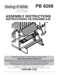
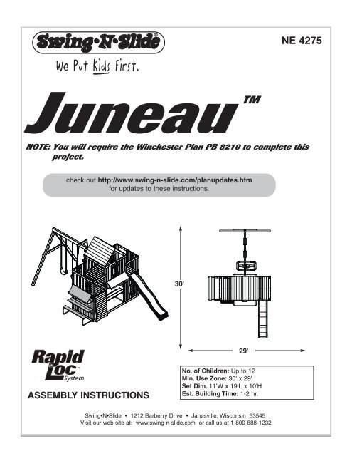
RNE 4275JuneauTMNOTE: You will require the Winchester Plan PB 8210 to complete thisproject.check out http://www.swing-n-slide.com/planupdates.htmfor updates to these instructions.30'29'ASSEMBLY INSTRUCTIONSNo. of Children: Up to 12Min. Use Zone: 30' x 29'Set Dim. 11'W x 19'L x 10'HEst. Building Time: 1-2 hr.<strong>Swing</strong>•N•<strong>Slide</strong> • 1212 Barberry Drive • Janesville, Wisconsin 53545Visit our web site at: www.swing-n-slide.com or call us at 1-800-888-1232
RSafety Checklist for <strong>Swing</strong>-N-<strong>Slide</strong> Play Sets and AccessoriesObserving the following statements and warnings reduces the likelihood of serious or fatal injuryInstallation Safety – Have You:Consulted the assembly instructions supplied with your particular model?Noted this accessory is to be used only on <strong>Swing</strong>•N•<strong>Slide</strong> approved designs? (Do not alter its design or add/remove components.)Made sure all hardware is tightened securely? (Supplied bolt covers must also be fastened securely.)Using a hacksaw, cut off all protruding threaded ends of bolts and other fasteners and remove any sharp edges witha metal file as needed?Placed the equipment on level ground, not less than six feet (1.8 meters) from any structure or obstruction such as a fence, garage,house, overhanging branches, laundry lines, or electrical wires?Made sure home playground equipment is not installed over concrete, asphalt, packed earth or any other hard surface? (A fall ontoa hard surface can result in serious injury to the equipment user.)Verified that suspended climbing ropes, chain,or cable are secured at both ends?Consulted in assembly instructions of your particular model for minimum use zones?Followed all anchoring and shock absorbing surfacing requirements on the back of this sheet as they apply?Made sure not to allow children to use equipment until it is properly installed?Operating Safety – Have You:Determined that on-site adult supervision is provided for children of all ages?Warned children the following before allowing them to use the equipment?Not to walk close to, in front of, behind or between moving items.Not to twist swing or any other accessory chains or ropes or loop them over the top support bar since this will reduce thestrength of chain or rope.Not to swing empty seats or other accessories.Be sure to sit in the center of the swing seat and other accessories with full weight on the seat.Not to attach items to the playground equipment that are not specifically designed for use with the equipment such as but notlimited to, jump ropes, clotheslines, pet leashes, cables and chain. They may cause a strangulation hazard.Not to use equipment in a manner other than intended.Not to get off equipment while it is in motion.Not to climb on the equipment when it is wet.Determined that only one child per planned occupant seat should be allowed on this set at one time.Determined children must be dressed appropriately for play. Avoid clothing with draw strings and loose fitting clothes whichcould become entangled or snagged on equipment.Determined that suspended climbing ropes, chain, or cable cannot be looped back upon itself.Read and understood the following warning regarding the use of two and four passenger lawn swings?Warning: Lawn <strong>Swing</strong>s are designed for use by children over two years of age. Use by children under the age of two can resultin entrapment between the seats and back areas. Never place children in a rearward facing position or with legs between theseat and backrest because the child’s body may pass through the opening causing entrapment of the child’s head.Safety Maintenance – Have You Determined to:Check all nuts and bolts twice monthly during the usage season for tightness and tighten as required? (It isparticularly important that this procedure be followed at the beginning of each season.)To prevent the deterioration of materials, remove plastic swing seats and other plastic accessories and take indoors? (Do notuse when the temperature drops below 0° F.)Oil all metallic moving parts monthly during usage period?Check all hardware and equipment for sharp edges twice monthly during usage season? (Replace whennecessary. It is especially important to do this at the beginning of each new season.)Check swing seats, chains, ropes and cables monthly during usage season for evidence of deterioration? Severe rusting or excessivewear, especially near the top swing hanger or at the seat connection are evidence of chain deterioration. Cracks in the protective plasticsleeve or seat itself are also signs of deterioration. If any of these conditions exist, call 1-800-888-1232 to order replacement accessories.Sand rusted metal parts and repaint using non-lead based paint.Disposal <strong>Instructions</strong>When the equipment is taken out of service, it must be disassembled and disposed of in such a way that no unreasonable hazardswill exist at the time the set is discarded.Important! Additional Safety <strong>Instructions</strong> for all <strong>Swing</strong>-N-<strong>Slide</strong> Playground Equipment.Save this instruction sheet in the event the manufacturer needs to be contacted.2
This product is intended for single family home/residential use only and not intended for use in any public setting.Placement in any public setting constitutes a misuse of this product.IMPORTANT!ADDITIONAL REQUIRED SAFETY INSTALLATION INSTRUCTIONSAccording to ASTM requirements, all kits must be anchored to the ground and, if the unit has a climbing rope, the rope end must be anchored to the ground. If soil conditionspermit stakes to be pulled out easily, cementing into ground is necessary.• To anchor the unit to the ground, Follow the instructions included in this plan for applying Anchor-It devices to your unit, or use 2" x 4" x 18" (45mm x 95mm x 457mm) pressuretreatedstakes. Pound stakes into ground at least 12" (305mm) at all inside corners of the posts (including A-frame legs and climbing unit posts). Attach with four (4) 16D (3-1/2")galvanized nails per stake into each 4" x 4" (95mm x 95mm) post.• If the unit has a climbing rope, anchor the rope end.• Once the unit is completely assembled and before children are allowed to play on it, proper shock-absorbing surfacing material must be installed. This may be accomplished byusing loose-fill materials at a sufficient depth. The Consumer Product Safety Commission “Handbook for Public Playground Safety” lists the following materials and requireddepths that are sufficient for home/residential application. For fall height protection up to 9 ft. (2.742m) [recommended for <strong>Swing</strong>•N•<strong>Slide</strong> kits]:LOOSE FILL MATERIALREQUIRED (UNCOMPRESSED) DEPTH 1 in. (mm)Wood Mulch9" (229mm)Double Shredded Bark Mulch9" (229mm)Uniform Wood Chips12" (305mm)Fine Sand12" (305mm)Fine Gravel12" (305mm)These depths were derived from the CPSC Handbook. <strong>Swing</strong>•N•<strong>Slide</strong> has not done independent tests to determine these required depths.When properly installed, shock absorbing material will completely cover the horizontal baseboards on climbing units. This protective surfacing must extend a minimum of 6 ft.(1.828m) in all directions from the perimeter of the equipment or from the outermost edges of any component. For example, a slide extending beyond the platform must haveprotective surfacing at least 6 ft. (1.828mm) out from both sides as well as the end. For swings, the protective surface must extend at least 14 ft. (6m) out from both the back andfront of the swing when the swing is in its rest position.NOTES:3
TOOLS REQUIREDTOOLS REQUIREDELECTRIC DRILL1/2" & 7/16'' SOCKETS WithWRENCHHAMMERTAPE MEASURESAFETY GLASSES& DUST MASK3/8" DRILL BIT (6'' Min.) PHILLIPS andSTRAIGHT BITCARPENTER'S SQUARE(14) 2" lag screw(4) 2-1/2'' carriage bolt(5) 3/4'' panhead screws(4) 5/16'' Loc-Nuts(8) 1/4'' Barrel Nut(6) 1/4'' flat washers(6) 3/4'' Truss Screw(8) 3/4'' Hex Head Bolt(5) 3/16'' flat washers(4) 5/16'' flat washers(4) Wood Loc Washers(16) 3/4'' screwsINCLUDED IN WINCHESTER KIT(173) 1-1/4'' screws(40) 2-1/2'' screws(1) T20 Torx® Bit(1) T30 Torx® Bit4
(2) Window Frame(2) Flower Box(1) Awning(1) Awning Support(2) Bench Supports (2) 'L' Brackets(2) Table Supports<strong>PlayHouse</strong>Plan(1) Plan5
<strong>PlayHouse</strong> <strong>Assembly</strong> <strong>Instructions</strong><strong>PlayHouse</strong> Board List(1) 1'' x 4'' x 7-3/4''(2) 1'' x 4'' x 11'' Window Top(2) 1'' x 4'' x 14''(4) 1'' x 4'' x 15-1/4'' Shutter(2) 1'' x 4'' x 19''(9) 1'' x 4'' x 22-1/4''(5) 1'' x 4'' x 34''(21) 1'' x 4'' x 40''(4) 1'' x 4'' x 40'' Window Cut(1) 1'' x 5'' x 29'' Offset Arch(1) 1'' x 5'' x 46'' Drape Cut(2) 1'' x 5'' x 47-1/2'' Drape Cut(2) 1'' x 6'' x 47-1/2''(1) 5/4'' x 6'' x 47-1/2''6
<strong>PlayHouse</strong> <strong>Assembly</strong> <strong>Instructions</strong><strong>PlayHouse</strong> Board List ModificationCut Down These (4) BoardsShaded Area Shows Wood To Be Removed(3) 1'' x 4'' x 30''Cut (3) 1'' x 4'' x 34'' to get (3) 1'' x 4'' x 30''(1) 1'' x 4'' x 23-1/2''Cut (1) 1'' x 4'' x 34'' to get (1) 1'' x 4'' x 23-1/2''How to select the correct fastenerUse these 2 pictorial guides to help select the correct fastener(s) for thelumber attachment you are making. Each diagram will highlight the correctnumber of fasteners to use and where to attach them.1'' x 4'' to 3'' x 3''(3) 2-1/2'' screwsApply 2-1/2" screws to the 1''x4'' boardswhen attaching to 3''x3'' uprights.1'' x 4'' to 1'' x 4''(2) 1-1/4'' screwsUse 1-1/4'' screws when mounting 1'' x 4''boards to 1'' x 4'' boards.7
<strong>PlayHouse</strong> <strong>Assembly</strong> <strong>Instructions</strong>Fig. 1Window SillFig. 1a1'' x 4'' x 23-1/2''(4)2-1/2'' screwsper jointA. Remove Window Sill and attachDeck Support1. Carefully remove Window Sill as shown in(Fig. 1) and retain with hardware for use later.2. Attach Deck Support Board as shown in(Fig. 1a).2-1/2'' screw8
<strong>PlayHouse</strong> <strong>Assembly</strong> <strong>Instructions</strong>Fig. 2(3)2-1/2'' screwsper joint1'' x 4'' x 30''1'' x 4'' x 30''1'' x 4'' x 30''(3)2-1/2'' screwsper jointB. Wall Supports1. Attach (3) <strong>PlayHouse</strong> wall supports as shown.2-1/2'' screw9
<strong>PlayHouse</strong> <strong>Assembly</strong> <strong>Instructions</strong>Fig. 3NOTE: Gap between all <strong>PlayHouse</strong>Wall Boards must be 1/4'' orLess. Mount As Flush AsPossible.1-1/2''Offset(2)1-1/4'' deck screwsper joint(7) 1'' x 4'' x 40''INSIDE VIEW1-1/4'' screwC. Install <strong>PlayHouse</strong> Wall1. Install (7) 1'' x 4'' x 40'' boards as shown in (Fig. 3).10
<strong>PlayHouse</strong> <strong>Assembly</strong> <strong>Instructions</strong>Fig. 4NOTE: Gap between all <strong>PlayHouse</strong>Wall Boards must be 1/4'' orLess. Mount As Flush AsPossible.(1) 1'' x 4'' x 11''Window Top(2)1-1/4'' deck screwsper joint1-1/4'' screwINSIDE VIEW1-1/2''Offset(1) 1'' x 4'' x 40''(2) 1'' x 4'' x 40''(1) 1'' x 4'' x 40''Window Cut(1) 1'' x 4'' x 14''Window Bottom(1) 1'' x 4'' x 40''Window CutD. Install <strong>PlayHouse</strong> Wall1. Install Window Barrier boards as shown in (Fig. 4).11
<strong>PlayHouse</strong> <strong>Assembly</strong> <strong>Instructions</strong>Fig. 4a(8)3/4'' Flat HeadscrewsPer Window3/4'' Flat HeadscrewD. Install Window Frames1. Install Window Frame, as shown in (Fig. 4a).NOTE: You may need to adjust Window Top Board toproperly align Window Frame with Opening.12
<strong>PlayHouse</strong> <strong>Assembly</strong> <strong>Instructions</strong>Fig. 5(2)1-1/4'' screwsper joint(3)3/4'' Truss screwsper jointFig. 5a3/4''Truss screw(3)3/4'' Truss screwsper joint1-1/4'' screwE. Install Shutters and Flower Boxes1. Hold Flower Box in place and mark all screw locations.2. Drive in screws, leaving a 1/8'' Gap between the Screw Head and the wood surface.3. Install the Flower Box and tighten all hardware, as shown in (Fig. 5).4. Attach Window Shutters as shown in (Fig 5).5. Repeat Steps 1-3 to install Flower Box in Upper Deck Window (replacing Window Sill) as shown in (Fig. 5a).13
<strong>PlayHouse</strong> <strong>Assembly</strong> <strong>Instructions</strong>Fig. 6NOTE: Gap between all <strong>PlayHouse</strong>Wall Boards must be 1/4'' orLess. Mount As Flush AsPossible.(2)1-1/4'' deck screwsper joint1-1/2''OffsetINSIDE VIEW(2) 1'' x 4'' x 40''(1) 1'' x 4'' x 40''(1) 1'' x 4'' x 40''Window Cut(1) 1'' x 4'' x 14''Window Bottom(1) 1'' x 4'' x 40''Window Cut(1) 1'' x 4'' x 11''Window Top1-1/4'' screwF. Install <strong>PlayHouse</strong> Wall1. Install Window Barrier boards as shown in (Fig. 6).14
<strong>PlayHouse</strong> <strong>Assembly</strong> <strong>Instructions</strong>Fig. 6a(8)3/4'' Flat HeadscrewsPer Window3/4'' Flat HeadscrewG. Install Window Frames1. Install Window Frame, as shown in (Fig. 6a).NOTE: You may need to adjust Window Top Board to properly align Window Frame with Opening.15
<strong>PlayHouse</strong> <strong>Assembly</strong> <strong>Instructions</strong>Fig. 6b(3)1-1/4'' screwsper joint1-1/4'' screwG. Install Shutters and Reinstall Window Sill1. Attach Window Shutters and re-install Window Sill you removed earlier as shown in (Fig 6b).16
<strong>PlayHouse</strong> <strong>Assembly</strong> <strong>Instructions</strong>Fig. 7(3)2-1/2'' screwsper joint1'' x 5'' x 47-1/2'' Drape BoardFig. 7aNOTE: Gap between all <strong>PlayHouse</strong>Wall Boards must be 1/4'' orLess. Mount As Flush AsPossible.Fig. 7b1'' x 4'' x 40''(4)1-1/4'' screws1-1/4'' screw(2)1-1/4'' deck screwsper joint2-1/2'' screw1-1/2''Offset(9) 1'' x 4'' x 22-1/4''G. <strong>PlayHouse</strong> Walls1. Install Drape Board as shonw in (Fig. 7).2. Install Filler Board as shown in (Fig. 7a).3. Attach <strong>PlayHouse</strong> Walls as shown in(Fig 7b).(2) 1'' x 4'' x 40''INSIDE VIEW17
<strong>PlayHouse</strong> <strong>Assembly</strong> <strong>Instructions</strong>Fig. 8(2)1-1/4'' screwsper joint1'' x 4'' x 40''Fig. 8a1-1/4'' screw(4)2-1/2'' screws1'' x 4'' x 34''2-1/2'' screwH. Barrier Supports1. Attach Barrier Support Boards as shown in(Fig. 8) and (Fig. 8a).18
<strong>PlayHouse</strong> <strong>Assembly</strong> <strong>Instructions</strong>Fig. 9Fig. 9aAlign boards sothey are Flushwith 3'' x 3'' outersurface on bothsides.24-1/4''(2) 1'' x 6'' x 47-1/2''Picnic TableBrackets(2)2'' Lag Screwsper jointMountBrackets in theCenter of theUprightsFig. 9bFig. 9c(4) 1/4''Barrel NutsPer SideInstall Last1'' x 4'' x 7-3/4''(3)1-1/4'' Deck ScrewsTemporarily RotateSupport For EasierHardware Installation(4) 3/4''Hex Head BoltsPer Side2'' Lag screw1-1/4'' screwI. Picnic Table1. Install Picnic Table Brackets as shown in (Fig. 9).2. Align 1'' x 6'' boards as shown in (Fig. 9a).3. Attach Picnic Table Support centered underneath the Picnic table and attach Table Supports as shown in (Fig. 9b).4. Using the “L” Brackets as templates, mark all hole locations of “L” Brackets on 1'' x 6'' board and drill one 3/8''hole at each marked spot.5. Secure 1'' x 6'' boards to “L” Braces as shown in (Fig. 9c).19
<strong>PlayHouse</strong> <strong>Assembly</strong> <strong>Instructions</strong>Fig. 10Fig. 10a(2)2'' Lag Screwsper jointCenter ofUprights5/4'' x 6'' x 47-1/2''Fig. 10b2-1/2'' Carriage BoltWood Loc Washer5/16'' Washer5/16'' Loc Nut2'' Lag screwJ. Picnic Bench1. Install (2) Picnic Bench Brackets as shown in (Fig. 10).2. Center (1) 5/4'' x 6'' board on the picnic Bench Brackets as shown in (Fig. 10a).3. Using the Picnic Bench Brackets as a template, mark each hole location.4. Drill one 3/8'' hole at each location.5. Secure the Picnic Bench in to the Picnic Bench Brackets as shown in (Fig. 10b).20
Fig. 11<strong>PlayHouse</strong> <strong>Assembly</strong> <strong>Instructions</strong>Fig. 11a<strong>Slide</strong> Support ThroughPocket on Awning1-1/2''(5) 3/4'' Pan Head Screwsand(5) Tarp WashersFig. 11bFig. 11c(1)2'' Lag ScrewPer Side(1)2'' Lag ScrewPer SideK. AwningTarp Washer2'' Lag screw3/4'' Pan Head screw1. <strong>Slide</strong> Awning Support through pocket on Awning bottom as shown in (Fig. 11).2. Attach 1/2'' of the top of the Awning to the top board using (5) 1/4'' screws and washers as shown in (Fig. 11a).3. Attach Awning Support to 3'' x 3'' uprights with (1) 2'' Lag Screw per side.4. Push lightly down on the Awning Support to make the Awning taught, as shown in (Fig. 11b). While one personmaintains the pressure on the Awning, have a helper secure the Awning Support in place with (1) additional 2'' Lagscrew on each side of the Awning Bar, as shown in (Fig. 11c).21
<strong>PlayHouse</strong> <strong>Assembly</strong> <strong>Instructions</strong>22
23<strong>PlayHouse</strong> <strong>Assembly</strong> <strong>Instructions</strong>
Questions???...Call our Customer Service Departmentat 1-800-888-1232R© PlayCore Inc. 2009 Printed In USA LA 6044