SERVICE MANUAL - Toshiba
SERVICE MANUAL - Toshiba
SERVICE MANUAL - Toshiba

You also want an ePaper? Increase the reach of your titles
YUMPU automatically turns print PDFs into web optimized ePapers that Google loves.
FILE NO. A05-004-1Revised: Jan./2006<strong>SERVICE</strong> <strong>MANUAL</strong>R410ASystem air conditionerThe indoor units in the Super Heat Recovery Multi System are common to those used in the Super Modular MultiSystem air conditioner. Therefore refer to the service manuals A03-009, A03-010, and A03-011 separately issued.Heat Recovery TypeIndoor Unit4-way Air Discharge Cassette TypeMMU-AP0091H, AP0121H, AP0151H,MMU-AP0181H, AP0241H, AP0271H,MMU-AP0301H, AP0361H, AP0481HMMU-AP0561H2-way Air Discharge Cassette TypeMMU-AP0071WH, AP0091WH, AP0121WH,MMU-AP0151WH, AP0181WH, AP0241WH,MMU-AP0271WH, AP0301WH, AP0481WH** CHINA market only1-way Air Discharge Cassette TypeMMU-AP0071YH, AP0091YH, AP0121YH,MMU-AP0151SH, AP0181SH, AP0241SH,MMU-AP0152SH, AP0182SH, AP0242SHConcealed Duct Standard TypeMMD-AP0071BH, AP0091BH, AP0121BH, AP0151BH,MMD-AP0181BH, AP0241BH, AP0271BH, AP0301BH,MMD-AP0361BH, AP0481BH, AP0561BHConcealed Duct High Static Pressure TypeMMD-AP0181H, AP0241H, AP0271H,MMD-AP0361H, AP0481HSlim Duct TypeMMD-AP0071SPH, AP0091SPH, AP0121SPH,MMD-AP0151SPH, AP0181SPHUnder Ceiling TypeMMC-AP0151H, AP0181H, AP0241H,MMC-AP0271H, AP0361H, AP0481HHigh Wall TypeMMK-AP0071H, AP0091H, AP0121H,MMK-AP0151H, AP0181H, AP0241H,MMK-AP0072H, AP0092H, AP0122HFloor Standing Cabinet TypeMML-AP0071H, AP0091H, AP0121H,MML-AP0151H, AP0181H, AP0241HFloor Standing Concealed TypeMML-AP0071BH, AP0091BH, AP0121BH,MML-AP0151BH, AP0181BH, AP0241BHFloor Standing TypeMMF-AP0151H, AP0181H, AP0241H,AP0271H,MMF-AP0361H, AP0481H, AP0561HOutdoor UnitInverter UnitMMY-MAP0802FT8MMY-MAP1002FT8MMY-MAP1202FT8Flow Selector Unit (FS unit)RBM-Y1122FERBM-Y1802FERBM-Y2802FEPRINTED IN JAPAN, Jan., 2006 ToMo
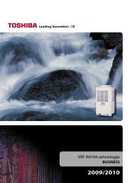
e.g., chargedamount (10kg)WARNINGS ON REFRIGERANT LEAKAGECheck of Concentration LimitThe room in which the air conditioner is to beinstalled requires a design that in the event ofrefrigerant gas leaking out, its concentration willnot exceed a set limit.The refrigerant R410A which is used in the airconditioner is safe, without the toxicity orcombustibility of ammonia, and is not restricted bylaws to be imposed which protect the ozone layer.However, since it contains more than air, it poses therisk of suffocation if its concentration should riseexcessively. Suffocation from leakage of R410A isalmost non-existent. With the recent increase in thenumber of high concentration buildings, however, theinstallation of multi air conditioner systems is on theincrease because of the need for effective use of floorspace, individual control, energy conservation bycurtailing heat and carrying power etc.Most importantly, the multi air conditioner system isable to replenish a large amount of refrigerantcompared with conventional individual air conditioners.If a single unit of the multi conditioner system is to beinstalled in a small room, select a suitable model andinstallation procedure so that if the refrigerantaccidentally leaks out, its concentration does notreach the limit (and in the event of an emergency,measures can be made before injury can occur).In a room where the concentration may exceed thelimit, create an opening with adjacent rooms, or installmechanical ventilation combined with a gas leakdetection device.The concentration is as given below.Total amount of refrigerant (kg)Min. volume of the indoor unit installed room (m³)≤ Concentration limit (kg/m³)The concentration limit of R410A which is used in multiair conditioners is 0.3kg/m³.NOTE 1 :If there are 2 or more refrigerating systems in a singlerefrigerating device, the amounts of refrigerant shouldbe as charged in each independent device.Outdoor unite.g.,charged amount (15kg)Room A Room B Room C Room D Room E Room FIndoor unitFor the amount of charge in this example:The possible amount of leaked refrigerant gas inrooms A, B and C is 10kg.The possible amount of leaked refrigerant gas inrooms D, E and F is 15kg.NOTE 2 :The standards for minimum room volume are asfollows.(1) No partition (shaded portion)(2) When there is an effective opening with theadjacent room for ventilation of leaking refrigerantgas (opening without a door, or an opening 0.15%or larger than the respective floor spaces at thetop or bottom of the door).Outdoor unitRefrigerant pipingIndoor unit(3) If an indoor unit is installed in each partitionedroom and the refrigerant tubing is interconnected,the smallest room of course becomes the object.But when a mechanical ventilation is installedinterlocked with a gas leakage detector in thesmallest room where the density limit is exceeded,the volume of the next smallest room becomes theobject.Refrigerant pipingVerysmallroomSmallroomMediumroomLarge roomMechanical ventilation device - Gas leak detectorOutdoor unitIndoor unitNOTE 3 :The minimum indoor floor area compared with theamount of refrigerant is roughly as follows:(When the ceiling is 2.7m high)40m² 35Min. indoor floor area302520151050ImportantRange below thedensity limitof 0.3 kg/m³(countermeasuresnot needed)Range abovethe density limitof 0.3 kg/m³(countermeasuresneeded)10 20 30Total amount of refrigerantkg
CONTENTSSAFETY CAUTION ............................................................................................ 41. OUTLINE ................................................................................................... 92. WIRING DIAGRAM ................................................................................. 143. PARTS RATING ...................................................................................... 304. REFRIGERANT PIPING SYSTEMATIC DRAWING ............................... 485. SYSTEM REFRIGERANT CYCLE DRAWING ....................................... 536. CONTROL OUTLINE .............................................................................. 607. APPLIED CONTROL .............................................................................. 718. TEST OPERATION ................................................................................. 869. TROUBLESHOOTING .......................................................................... 11610. CONFIGURATION OF CONTROL CIRCUIT ........................................ 17411. BACKUP OPERATIONS (EMERGENCY OPERATION)....................... 18812. OIL LEVEL JUDGMENT DISPLAY ....................................................... 19013. REFRIGERANT RECOVERYWHEN REPLACING THE COMPRESSOR ........................................... 19114. LEAKAGE/CLOGGING OF OIL-EQUALIZATION CIRCUIT................. 19715. REPLACING COMPRESSOR............................................................... 19916. REPLACING PROCEDURE OF PARTS ............................................... 20617. P.C. BOARD .......................................................................................... 217NOTEEnsure power is isolated from the unit when replacing the high performance filter or when opening theservice panel.
SAFETY CAUTIONThe important contents concerned to the safety are described on the product itself and on this Service Manual.Please read this Service Manual after understanding the described items thoroughly in the following contents(Indications/Illustrated marks), and keep them.[Explanation of indications]IndicationDANGERWARNINGCAUTIONExplanationIndicates contents assumed that an imminent danger causing a death or serious injury ofthe repair engineers and the third parties when an incorrect work has been executed.Indicates possibilities assumed that a danger causing a death or serious injury of therepair engineers, the third parties, and the users due to troubles of the product after workwhen an incorrect work has been executed.Indicates contents assumed that an injury or property damage (∗) may be caused on therepair engineers, the third parties, and the users due to troubles of the product after workwhen an incorrect work has been executed.∗ Property damage : Enlarged damage concerned to property, furniture, and domestic animal/pet[Explanation of illustrated marks]MarkExplanationIndicates prohibited items (Forbidden items to do)The sentences near an illustrated mark describe the concrete prohibited contents.Indicates mandatory items (Compulsory items to do)The sentences near an illustrated mark describe the concrete mandatory contents.Indicates cautions (including danger/warning)The sentences or illustration near or in an illustrated mark describe the concrete cautious contents.[Confirmation of warning label on the main unit]Confirm that labels are indicated on the specified positions(Refer to the Parts disassembly diagram (Outdoor unit).)If removing the label during parts replace, stick it as the original.DANGERTurn off breaker.Execute dischargebetween terminals.Turn “OFF” the breaker before removing the front panel and cabinet, otherwise an electricshock is caused by high voltage resulted in a death or injury.During operation, a high voltage with 400V or higher of circuit (∗) at secondary circuit of the highvoltagetransformer is applied.If touching a high voltage with the naked hands or body, an electric shock is caused even if using anelectric insulator.∗ : For details, refer to the electric wiring diagram.When removing the front panel or cabinet, execute short-circuit and discharge between highvoltagecapacitor terminals.If discharge is not executed, an electric shock is caused by high voltage resulted in a death or injury.After turning off the breaker, high voltage also keeps to apply to the high-voltage capacitor.Do not turn on the breaker under condition that the front panel and cabinet are removed.An electric shock is caused by high voltage resulted in a death or injury.Prohibition4
WARNINGCheck earth wires.Prohibition of modification.Use specified parts.Do not bring a childclose to the equipment.Insulating measuresNo fireRefrigerantAssembly/CablingBefore troubleshooting or repair work, check the earth wire is connected to the earthterminals of the main unit, otherwise an electric shock is caused when a leak occurs.If the earth wire is not correctly connected, contact an electric engineer for rework.Do not modify the products.Do not also disassemble or modify the parts. It may cause a fire, electric shock or injury.For spare parts, use those specified (∗).If unspecified parts are used, a fire or electric shock may be caused.∗: For details, refer to the parts list.Before troubleshooting or repair work, do not bring a third party (a child, etc.) exceptthe repair engineers close to the equipment.It causes an injury with tools or disassembled parts.Please inform the users so that the third party (a child, etc.) does not approach the equipment.Connect the cut-off lead cables with crimp contact, etc, put the closed end sideupward and then apply a water-cut method, otherwise a leak or production of fire iscaused at the users’ side.When repairing the refrigerating cycle, take the following measures.1) Be attentive to fire around the cycle. When using a gas stove, etc, be sure to put out firebefore work; otherwise the oil mixed with refrigerant gas may catch fire.2) Do not use a welder in the closed room. When using it without ventilation, carbonmonoxide poisoning may be caused.3) Do not bring inflammables close to the refrigerant cycle, otherwise fire of the welder maycatch the inflammables.Check the used refrigerant name and use tools and materials of the parts whichmatch with it.For the products which use R410A refrigerant, the refrigerant name is indicated at aposition on the outdoor unit where is easy to see. To prevent miss-charging, the route of theservice port is changed from one of the former R22.For an air conditioner which uses R410A, never use other refrigerant than R410A.For an air conditioner which uses other refrigerant (R22, etc.), never use R410A.If different types of refrigerant are mixed, abnormal high pressure generates in the refrigeratingcycle and an injury due to breakage may be caused.Do not charge refrigerant additionally.If charging refrigerant additionally when refrigerant gas leaks, the refrigerant composition inthe refrigerating cycle changes resulted in change of air conditioner characteristics orrefrigerant over the specified standard amount is charged and an abnormal high pressure isapplied to the inside of the refrigerating cycle resulted in cause of breakage or injury.Therefore if the refrigerant gas leaks, recover the refrigerant in the air conditioner, executevacuuming, and then newly recharge the specified amount of liquid refrigerant. In this time,never charge the refrigerant over the specified amount.When recharging the refrigerant in the refrigerating cycle, do not mix the refrigerantor air other than R410A into the specified refrigerant.If air or others is mixed with the refrigerant, abnormal high pressure generates in therefrigerating cycle resulted in cause of injury due to breakage.After installation work, check the refrigerant gas does not leak.If the refrigerant gas leaks in the room, poisonous gas generates when gas touches to firesuch as fan heater, stove or cocking stove though the refrigerant gas itself is innocuous.Never recover the refrigerant into the outdoor unit.When the equipment is moved or repaired, be sure to recover the refrigerant with recoveringdevice. The refrigerant cannot be recovered in the outdoor unit; otherwise a seriousaccident such as breakage or injury is caused.After repair work, surely assemble the disassembled parts, and connect and lead theremoved cables as before. Perform the work so that the cabinet or panel does notcatch the inner cables.If incorrect assembly or incorrect cable connection was done, a disaster such as a leak orfire is caused at user’s side.5
WARNINGInsulator checkVentilationBe attentive toelectric shockCompulsionAfter the work has finished, be sure to use an insulation tester set (500V mugger) tocheck the resistance is 2MΩ or more between the charge section and the non-chargemetal section (Earth position).If the resistance value is low, a disaster such as a leak or electric shock is caused at user’sside.When the refrigerant gas leaks during work, execute ventilation.If the refrigerant gas touches to a fire, poisonous gas generates. A case of leakage of therefrigerant and the closed room full with gas is dangerous because a shortage of oxygenoccurs. Be sure to execute ventilation.When checking the circuit inevitably under condition of the power-ON, use rubbergloves and others not to touch to the charging section.If touching to the charging section, an electric shock may be caused.When the refrigerant gas leaks, find up the leaked position and repair it surely.If the leaked position cannot be found up and the repair work is interrupted, pump-downand tighten the service valve, otherwise the refrigerant gas may leak into the room.The poisonous gas generates when gas touches to fire such as fan heater, stove or cockingstove though the refrigerant gas itself is innocuous.When installing equipment which includes a large amount of charged refrigerant suchas a multi air conditioner in a sub-room, it is necessary that the density does not thelimit even if the refrigerant leaks.If the refrigerant leaks and exceeds the limit density, an accident of shortage of oxygen iscaused.For the installation/moving/reinstallation work, follow to the Installation Manual.If an incorrect installation is done, a trouble of the refrigerating cycle, water leak, electricshock or fire is caused.After repair work has finished, check there is no trouble.If check is not executed, a fire, electric shock or injury may be caused. For a check, turn offthe power breaker.Check after rerairCheck after reinstallationAfter repair work (installation of front panel and cabinet) has finished, execute a testrun to check there is no generation of smoke or abnormal sound.If check is not executed, a fire or an electric shock is caused. Before test run, install thefront panel and cabinet.Check the following items after reinstallation.1) The earth wire is correctly connected.2) The power cord is not caught in the product.3) There is no inclination or unsteadiness and the installation is stable.If check is not executed, a fire, an electric shock or an injury is caused.CAUTIONPut on glovesCooling checkBe sure to put on gloves (∗) during repair work.If not putting on gloves, an injury may be caused with the parts, etc.(∗) Heavy gloves such as work glovesWhen the power was turned on, start to work after the equipment has beensufficiently cooled.As temperature of the compressor pipes and others became high due to cooling/heatingoperation, a burn may be caused.6
7• New Refrigerant (R410A)This air conditioner adopts a new HFC type refrigerant (R410A) which does not deplete the ozone layer.1. Safety Caution Concerned to New RefrigerantThe pressure of R410A is high 1.6 times of that of the former refrigerant (R22). Accompanied with change ofrefrigerant, the refrigerating oil has been also changed. Therefore, be sure that water, dust, the former refrigerantor the former refrigerating oil is not mixed into the refrigerating cycle of the air conditioner with new refrigerantduring installation work or service work. If an incorrect work or incorrect service is performed, there is apossibility to cause a serious accident. Use the tools and materials exclusive to R410A to purpose a safe work.2. Cautions on Installation/Service(1) Do not mix the other refrigerant or refrigerating oil.For the tools exclusive to R410A, shapes of all the joints including the service port differ from those of theformer refrigerant in order to prevent mixture of them.(2) As the use pressure of the new refrigerant is high, use material thickness of the pipe and tools which arespecified for R410A.(3) In the installation time, use clean pipe materials and work with great attention so that water and others donot mix in because pipes are affected by impurities such as water, oxide scales, oil, etc. Use the cleanpipes.Be sure to brazing with flowing nitrogen gas. (Never use gas other than nitrogen gas.)(4) For the earth protection, use a vacuum pump for air purge.(5) R410A refrigerant is azeotropic mixture type refrigerant. Therefore use liquid type to charge the refrigerant.(If using gas for charging, composition of the refrigerant changes and then characteristics of the air conditionerchange.)3. Pipe MaterialsFor the refrigerant pipes, copper pipe and joints are mainly used. It is necessary to select the most appropriatepipes to conform to the standard. Use clean material in which impurities adhere inside of pipe or joint to aminimum.4. Tools(1) Required Tools for R410AMixing of different types of oil may cause generation of sludge, clogging of capillary, etc.Accordingly, the tools to be used are classified into the following three types.1) Tools exclusive for R410A (Those which cannot be used for conventional refrigerant (R22))2) Tools exclusive for R410A, but can be also used for conventional refrigerant (R22)3) Tools commonly used for R410A and for conventional refrigerant (R22)The table below shows the tools exclusive for R410A and their interchangeability.No.Tools exclusive for R410A (The following tools for R410A are required.)Tools whose specifications are changed for R410A and their interchangeabilityUsed toolFlare toolCopper pipe gauge foradjusting projectionmarginTorque wrenchGauge manifoldCharge hoseVacuum pump adapterElectronic balance forrefrigerant chargingRefrigerant cylinderPipe flaringUsageFlaring by conventionalflare toolConnection of flare nutEvacuating, refrigerantcharge, run check, etc.Vacuum evacuatingRefrigerant chargeRefrigerant chargeR410Aair conditioner installationExistence ofnew equipmentfor R410AYesYesYesYesYesYesYesWhether conventionalequipment canbe used*(Note 1)*(Note 1)NoNoNoYesNoConventional airconditioner installationWhether new equipmentcan be used withconventional refrigerantYes*(Note 1)NoNoYesYesNo(1) Copper pipeLeakage detectorCharging cylinderGas leakage checkRefrigerant chargeYes(Note 2)NoNoYesNoThe pipe thickness, flare finishing size, flare nut and others differ according to a refrigerant type.When using a long copper pipe for R410A, it is recommended to select “Copper or copper-base pipe withoutseam” and one with bonded oil amount 40mg/10m or less. Also do not use crushed, deformed, discolored(especially inside) pipes. (Impurities cause clogging of expansion valves and capillary tubes.)Use the flare nuts which are attached to the air conditioner unit.(2) JointThe flare joint and socket joint are used for joints of the copper pipe. The joints are rarely used for installationof the air conditioner. However clear impurities when using them.(Note 1) When flaring is carried out for R410A using the conventional flare tools, adjustment of projectionmargin is necessary. For this adjustment, a copper pipe gauge, etc. are necessary.(Note 2) Charging cylinder for R410A is being currently developed.General tools (Conventional tools can be used.)In addition to the above exclusive tools, the following equipments which serve also for R22 are necessaryas the general tools.(1) Vacuum pump(7) Screwdriver (+, –)Use vacuum pump by(8) Spanner or Monkey wrenchattaching vacuum pump adapter.(9) Hole core drill(2) Torque wrench(10) Hexagon wrench (Opposite side 4mm)(3) Pipe cutter(11) Tape measure(4) Reamer(12) Metal saw(5) Pipe bender(6) Level vialAlso prepare the following equipments for other installation method and run check.(1) Clamp meter(3) Insulation resistance tester (Megger)(2) Thermometer(4) Electroscope (Volt meter)
5. Recharge of RefrigerantWhen recharge of the refrigerant is required, charge the new refrigerant with the specified amount in theprocedure as described below.Recover the refrigerant and check there is no refrigerant in theequipment.Connect the charge hose to the packed valve service ports at gasside, liquid side, and balance side of the outdoor unit.Connect the charge hose to vacuum pump adaptor.Open the packed valves of the balance pipe fully at liquid and gassides, and then return the valve at gas side a little to the closed side.Leave it as it is for 1 to 2 minutes and check the indicatorof the compound gauge does not return.Set the refrigerant cylinder on the electronic balance,connect the charge hose to connecting ports of thecylinder and the electronic gauge, and then charge theliquid refrigerant from the service port at liquid side.(Shield with the gauge manifold so that refrigerant doesnot flow to gas side.)(Charge the refrigerant as below.)Open fully PMV of the outdoor unit.• Turn on power of the outdoor unit.• Short CN30 on I/F P.C. board of the outdoor unit.• Turn off power of the outdoor unit within 2 minutes after shorting CN30.Open fully the handle on the Low side of the gauge manifold, andthen turn on the power of vacuum pump for vacuuming.When the pressure has lowered until indication of the compoundgauge pointed –0.1MPa (–76cmHg), open fully the handle Low andturn off the power of vacuum pump.Never charge the refrigerant over the specified amount.‚ Do not charge the additional refrigerant.If charging refrigerant additionally when refrigerant gasleaks, the refrigerant composition in the refrigerating cyclechanges resulted in change of air conditioner characteristicsor refrigerant over the specified standard amount ischarged and an abnormal high pressure is applied to theinside of the refrigerating cycle resulted in cause ofbreakage or injury.Connected toindoor unitMainpipeBrazedFullytightenedFullytightenedValve fully closed(gas side)Center unitValve fully closed(liquid side)Valve fully closed(balance)Connected to otherterminal unitsLowpressuregaugeServiceport Ø6.4Copper pipeService portVLHighpressuregaugeVHGaugemanifoldReducingvalveNitrogengasØ6.4Copper pipe4mm-hexagonal wrench is required.Set the equipment so that liquid refrigerant can be charged.‚ When using a cylinder with siphon pipe, liquid can be charged without inverting the cylinder.[ Cylinder with siphon ] [ Cylinder without siphon ]Gauge manifoldGauge manifoldOUTDOOR unitOUTDOOR unitSiphonRefrigerantcylinderRefrigerantcylinderElectronicbalanceElectronicbalanceR410A refrigerant is consisted with HFC mixed refrigerant.Therefore if the refrigerant gas is charged, the compositionof the charged refrigerant changes and characteristics ofthe equipment changes.6. Environmental concernUse “Vacuum pump method” for an air purge (Discharge of air in the connecting pipe) in installation time.• Do not discharge flon gas into the air to protect the earth environment.• Using the vacuum pump method, clear the remaining air (Nitrogen, etc.) in the unit. If the air remains, thepressure in the refrigerating cycle becomes abnormally high and an injury could occur through failure ofthe product.8
1. OUTLINE“Super Heat Recovery Multi System” is a multi air conditioning system which enables eachindoor unit in a refrigerant line to independently select cooling or heating operation.As it is able to operate simultaneously in cooling and heating modes, further heat recoverybecomes possible. This system is most suitable for a building etc. where cool and hot air aremixed, such as a building where there are large temperature differences between rooms,caused by the influence of daylight or where used in a server room and permanent cooling isrequired.Heating and cooling operation are automatically selected in individual unit;You can save time for operation.For example, when heating is required for early morning and cooling for daytime, a Flow Selector Unit providesautomatically a smooth selection of heating or cooling operation.Therefore you can obtain a comfortable room environment without feeling somewhat out of place and moreoveryou can save time to select heat/cool operation.INFORMATIONThe Super Heat Recovery Multi system is different from that of the conventional Multi air conditioner in severalways such as the heating and cooling operations are mixed and only a part of the air conditioning systemoperates in cooling function.For this reason, the following table explains the operation modes of this air conditioner.The following table explains the representation of the operation modes within this Manual.Operation modeOperation modeOutline1. All Cooling All indoor units are under cooling operation only.Outdoor heat exchanger (Main heat exchanger) is used as condenser.2. All Heating All indoor units are under heating operation only.Outdoor heat exchanger (Main heat exchanger) is used as evaporator.3. Simultaneous operation MIU for simultaneous operation3-1. Mainly cooling, partlyheating operation3-2. Mainly heating, partlycooling operationIndoor units are under heating/cooling simultaneous operation with subjective cooling operationOutdoor heat exchanger (Sub heat exchanger) is used as condenser.Indoor units are under heating/cooling simultaneous operation with subjective heating operationOutdoor heat exchanger (Main heat exchanger) is used as evaporator.4. Defrost Using the reversing operation of the 4-way valve, ice on the outdoor heat exchanger is dissolvedwithin single cooling cycle.9
1-1. Component Multi Using High-efficiency Refrigerant R410A1. Outdoor unitsCorresponding HPInverter unit8 HP 10 HP 12 HPAppearanceModel name Heat pump MMY- MAP0802FT8 MAP1002FT8 MAP1202FT8Cooling capacity (kW) 22.4 28.0 33.5Heating capacity (kW) 25.0 31.5 37.5No. of connectable indoor units 13 16 202. Combination of outdoor unitsCorresponding HP 16 HP 18 HP 20 HP 24 HP 26 HP 28 HP 30 HPCombined Model MMY- AP1602FT8 AP1802FT8 AP2002FT8 AP2402FT8 AP2602FT8 AP2802FT8 AP3002FT8Cooling capacity (kW) 45.0 50.4 56.0 68.0 73.0 78.5 84.0Heating capacity (kW) 50.0 56.5 63.0 76.5 81.5 88.0 95.08 HP 10 HP 10 HP 8 HP 10 HP 10 HP 10 HPCombined outdoor units8 HP 8 HP 10 HP 8 HP 8 HP 10 HP 10 HP— — — 8 HP 8 HP 8 HP 10 HPNo. of connectable indoor units 27 30 33 40 43 47 483. Branching joints and headersY-shape branching joint (∗3)4-branching header (∗4)8-branching header (∗4)T-branch jointModel name Usage AppearanceRBM-BY53FE Indoor unit capacity code (∗1) Total below 6.4RBM-BY103FE Indoor unit capacity code (∗1) Total below 14.2RBM-BY53E Indoor unit capacity code (∗1) Total below 6.4RBM-BY103E Indoor unit capacity code (∗1) Total below 14.2RBM-BY203FE Indoor unit capacity code (∗1) Total below 25.2RBM-BY303FE Indoor unit capacity code (∗1) Total below 25.2RBM-BY203E Indoor unit capacity code (∗1) Total below 25.2RBM-BY303E Indoor unit capacity code (∗1) Total below 25.2RBM-1043FE Indoor unit capacity code (∗1) Total below 14.2RBM-2043FE Indoor unit capacity code (∗1) Total below 25.2RBM-1043E Indoor unit capacity code (∗1) Total below 14.2RBM-2043E Indoor unit capacity code (∗1) Total below 25.2RBM-1083FE Indoor unit capacity code (∗1) Total below 14.2RBM-2083FE Indoor unit capacity code (∗1) Total below 25.2RBM-1083E Indoor unit capacity code (∗1) Total below 14.2RBM-2083E Indoor unit capacity code (∗1) Total below 25.2BT13-FEThe following 3 types of T joint pipes are supplied as 1 set.• Balance pipe (Ø9.5) × 1• Liquid side(Corresponded dia. Ø12.7 to Ø19.1) × 1• Suction gas side(Corresponded dia. Ø22.2 to Ø34.9) × 1• Discharge gas side(Corresponded dia. Ø19.1 to Ø22.2) × 1For 3 pipingFor 2 piping (∗5)For 3 pipingFor 2 piping (∗5)For 3 pipingFor 2 piping (∗5)For 3 pipingFor 2 piping (∗5)∗1∗2∗3∗4∗5∗6“Capacity code” can be obtained from page 11, 12. (Capacity code is not actual capacity)If the total capacity code value of indoor unit exceeds that of the outdoor unit, apply capacity code of the outdoor unit.When using a Y-shape branching joint for 1st branching, select according to the capacity code of the outdoor unit.Max. 6.0 capacity code in total can be connected.This is used for branching to “cooling only” indoor unit.Model names for outdoor described in this guide are shortened because of the space constraint.10
4. Flow selector units (FS unit)Model name Usage AppearanceRBM-Y1121FE Capacity rank for indoor unit : Type 007 to 030RBM-Y1801FE Capacity rank for indoor unit : Type 036 to 056RBM-Y2802FE Capacity rank for indoor unit : Type 018 to 096* Accessory part (Sold separately): Connection cable kit (RBC-CBK15FE), up to 15m.5. Indoor unitsType Appearance Model name Capacity rank Capacity code4-way Air DischargeCassette Type2-way Air DischargeCassette Type1-way Air DischargeCassette TypeCoolingcapacity (kW)Heatingcapacity (kW)MMU-AP0091H 009 type 1 2.8 3.2MMU-AP0121H 012 type 1.25 3.6 4.0MMU-AP0151H, 015 type 1.7 4.5 5.0MMU-AP0181H 018 type 2 5.6 6.3MMU-AP0241H 024 type 2.5 7.1 8.0MMU-AP0271H 027 type 3 8.0 9.0MMU-AP0301H 030 type 3.2 9.0 10.0MMU-AP0361H 036 type 4 11.2 12.5MMU-AP0481H 048 type 5 14.0 16.0MMU-AP0561H 056 type 6 16.0 18.0MMU-AP0071WH 007 type 0.8 2.2 2.5MMU-AP0091WH 009 type 1 2.8 3.2MMU-AP0121WH 012 type 1.25 3.6 4.0MMU-AP0151WH 015 type 1.7 4.5 5.0MMU-AP0181WH 018 type 2 5.6 6.3MMU-AP0241WH 024 type 2.5 7.1 8.0MMU-AP0271WH 027 type 3 8.0 9.0MMU-AP0301WH 030 type 3.2 9.0 10.0MMU-AP0481WH(CHINA only)048 type 5 14.0 16.0MMU-AP0071YH 007 type 0.8 2.2 2.5MMU-AP0091YH 009 type 1 2.8 3.2MMU-AP0121YH 012 type 1.25 3.6 4.0MMU-AP0151SH 015 type 1.7 4.5 5.0MMU-AP0181SH 018 type 2 5.6 6.3MMU-AP0241SH 024 type 2.5 7.1 8.0MMU-AP0152SH 015 type 1.7 4.5 5.0MMU-AP0182SH 018 type 2 5.6 6.3MMU-AP0242SH 024 type 2.5 7.1 8.0Concealed DuctStandard TypeMMD-AP0071BH 007 type 0.8 2.2 2.5MMD-AP0091BH 009 type 1 2.8 3.2MMD-AP0121BH 012 type 1.25 3.6 4.0MMD-AP0151BH 015 type 1.7 4.5 5.0MMD-AP0181BH 018 type 2 5.6 6.3MMD-AP0241BH 024 type 2.5 7.1 8.0MMD-AP0271BH 027 type 3 8.0 9.0MMD-AP0301BH 030 type 3.2 9.0 10.0MMD-AP0361BH 036 type 4 11.2 12.5MMD-AP0481BH 048 type 5 14.0 16.0MMD-AP0561BH 056 type 6 16.0 18.011
Type Appearance Model name Capacity rank Capacity codeConcealed DuctHigh StaticPressure TypeSlim Duct TypeUnder Ceiling TypeHigh Wall TypeFloor StandingCabinet TypeFloor StandingConcealed TypeFloor Standing TypeCoolingcapacity (kW)Heatingcapacity (kW)MMD-AP0181H 018 type 2 5.6 6.3MMD-AP0241H 024 type 2.5 7.1 8.0MMD-AP0271H 027 type 3 8.0 9.0MMD-AP0361H 036 type 4 11.2 12.5MMD-AP0481H 048 type 5 14.0 16.0MMD-AP0071SPH 007 type 0.8 2.2 2.5MMD-AP0091SPH 009 type 1 2.8 3.2MMD-AP0121SPH 012 type 1.25 3.6 1.0MMD-AP0151SPH 015 type 1.7 4.5 5.0MMD-AP0181SPH 018 type 2 5.6 6.3MMC-AP0151H 015 type 1.7 4.5 5.0MMC-AP0181H 018 type 2 5.6 6.3MMC-AP0241H 024 type 2.5 7.1 8.0MMC-AP0271H 027 type 3 8.0 9.0MMC-AP0361H 036 type 4 11.2 12.5MMC-AP0481H 048 type 5 14.0 16.0MMK-AP0071H 007 type 0.8 2.2 2.5MMK-AP0091H 009 type 1 2.8 3.2MMK-AP0121H 012 type 1.25 3.6 4.0MMK-AP0151H 015 type 1.7 4.5 5.0MMK-AP0181H 018 type 2 5.6 6.3MMK-AP0241H 024 type 2.5 7.1 8.0MMK-AP0072H 007 type 0.8 2.2 2.5MMK-AP0092H 009 type 1 2.8 3.2MMK-AP0122H 012 type 1.25 3.6 4.0MML-AP0071H 007 type 0.8 2.2 2.5MML-AP0091H 009 type 1 2.8 3.2MML-AP0121H 012 type 1.25 3.6 4.0MML-AP0151H 015 type 1.7 4.5 5.0MML-AP0181H 018 type 2 5.6 6.3MML-AP0241H 024 type 2.5 7.1 8.0MML-AP0071BH 007 type 0.8 2.2 2.5MML-AP0091BH 009 type 1 2.8 3.2MML-AP0121BH 012 type 1.25 3.6 4.0MML-AP0151BH 015 type 1.7 4.5 5.0MML-AP0181BH 018 type 2 5.6 6.3MML-AP0241BH 024 type 2.5 7.1 8.0MMF-AP0151H 015 type 1.7 4.5 5.0MMF-AP0181H 018 type 2 5.6 6.3MMF-AP0241H 024 type 2.5 7.1 8.0MMF-AP0271H 027 type 3 8.0 9.0MMF-AP0361H 036 type 4 11.2 12.5MMF-AP0481H 048 type 5 14.0 16.0MMF-AP0561H 056 type 6 16.0 18.012
n Remote controllersNameWired remote controllerSimple wired remote controllerWeekly timerSET DATA SETTING TESTHUNIT No.R.C.No.CODE No.TESTSETTING˚C˚FPROGRAM1PROGRAM2SuMoTuWeTh Fr SaERRORPROGRAM3AppearanceTEMP.ON / OFFWEEKLY TIMERTIMER SETFANMODETIMESWING/FIXVENTFILTERRESET TESTSETCLUNITModel nameRBC-AMT31ERBC-AS21ERBC-EXW21ENameWireless remote controller kitReceiver sectionReceiver sectionmounted separatelyAppearanceADR ADR ADRReceiver sectionModel nameRBC-AX2U (W)-ERBC-AX22CETCB-AX21EType4-way Air DischargeCassette typeUnder Ceiling type1-way Air Discharge Cassettetype (MMU-AP✽✽✽2SH Series)Separate sensor typeNameCentral remote controllerALL ZONEZONEGROUP1234UNIT No.TESTCODENo.AppearanceSET DATASETTINGR.C.No.SELECTZONEGROUPCLSETModel nameTypeTCB-SC642TLE64 system center controller13
14Indoor unitR(L) S(N)Earth screwSymbolFMTATC1TCJTC2LM1, LM2DMFSRY302PMVPower supplySingle phase220-240V 50Hz220V 60HzDMFlow selectorunit earthscrewREDWHIClosed endconnectorParts nameFan motorIndoor temp sensorTemp sensorTemp sensorTemp sensorLouver motorDrain pump motorFloat switchDrain control relayPulse Motor ValveCN68(BLU)123CN304(GRY)RED1CN67(BLK)23WHIBLKCN66(WHI)CN44(BLN)1231231231212RY302RY303FuseT6.3A250V~P301CN50(WHI)1 2 35 4 3 2 1 CN3345 4 3 2 1 (BLU)~ +~CN32(WHI)(Fandrive)FMPMV6 4 3 1 2 56 4 3 1 2 51 2 3 4 5 CN333 1 2 3 4 5 61 2 3 4 5 (WHI) 1 2 3 4 5 6Motor drivecircuitCN61(YEL)1 2 3 4 5FuseT3.15A250V~CN60(WHI)1 2(Option)CN82(BLU)DC20VDC15VDC12VDC7VCN81(BLK)4 5 1 2 T10 6 3 4 5 6 1 2 3 4 51. indicates the terminal block, letter at insideindicates the terminal number.2. A dotted line and broken line indicate the wiring at site.3. indicates the control P.C. board.RED : REDWHI : WHITEYEL : YELLOWBLU : BLUEBRN : BROWNColor identificationBLK : BLACKGRY : GRAYPNK : PINKORN : ORANGEGRN : GREENU1PowersupplycircuitU2Outdoor unitU1U2WHIALM21 2 3 4 51 2 3 4 51 2 3 4 51 2 3 4 51 2 3 4 51 2 3 4 5Indoor control P.C. boardMCC-1402BCN1(WHI)1 21 2Wired remotecontrollerCN40(BLU)1 21 2BLUBLUBLKCN41(BLU)1 2 31 2 3BLK WHI BLKBLKBLKWHICN001(WHI)1 21 2Adaptor for wirelessremote controllerCN309(YEL)CN01(WHI)3 32 21 1CN02(BLU)LM11 2 3 4 51 2 3 4 5CN33(WHI)1 2 31 2 31 21 21 2 CN031 2 (RED)X YTR3 13 2 1CN104(YEL)CN102(RED)CN101(BLK)CN100(BRN)CN80(GRN)CN73(RED)CN20 CN70(BLU) (WHI)1 2 3 4 5Network adaptor(Option)NetworkadaptorP.C. boardMCC-1401FSCN34(RED)1212121212121 12 23 312PNL31212EXCTTATCJTC2Filter inputTC1Model: MMU-AP0091H, AP0121H, AP0151H, AP0181H, AP0241H,MMU-AP0271H, AP0301H, AP0361H, AP0481H, AP0561H2-1-1. 4-way Air Discharge Cassette Type2-1. Indoor Unit2. WIRING DIAGRAM
15ColorindicationRED : REDWHI : WHITEYEL : YELLOWBLU : BLUEBLK : BLACKGRY : GRAYPNK : PINKORN : ORANGEBRW : BROWNGRN : GREENIndoor unitEarth screwR(L) S(N)Power supplySingle phase220-240V 50Hz220V 60HzFMFlow selectorunit earthscrewClosed endconnectorCN039(YEL)WHI1 12 2RED3 34 45 56 67 79(BLK)CN304(GRY)CN066(WHI)CN044 1(BRW) 2TR123123U112312312312Line FilterCN067(BLK)CN040(BLU)1 21 2BLUBLUU2Outdoor unitP301U1RY004U2FuseT5.0ABLK250V~CN041(BLU)1 2 31 2 3ABLKBREDFANCN083(WHI)XCN1(WHI)1 21 2Remote controllerY3 321 1CN02(BLU)RCBLK9 8 7 69 8 7 6RY007CN01(WHI)ORNCN050(WHI)1 2 3 4 51 21 2MCC-1401BLU5 4 3 2 15 4 3 2 1RY006RY005Networkadaptor(Option)YELH M L UL1 12 2CN03(RED)RY002CN074(WHI)DM1 2 31 2 31 2 31 2 3DP(BLU)CN068RY001LM1 21 21 2 31 2 3Power supplycircuit1 2 3 4 5 61 2 3 4 5 61 2 3 4 5 61 2 3 4 5 6Sub P.C. boardMCC-15201 2 3 4 5 61 2 3 4 5 6LM(GRN)CN033Indoor control P.C. boardCN075(WHI)CN02(YEL)CN01(WHI)TR1 2 31 2 3FSCN061(YEL)1. indicates the terminal block, letter at insideindicates the terminal number.2. A dotted line and broken line indicate the wiring at site.3. indicates the control P.C. board.FS(RED)CN030CN032(WHI)6 4 36 4 31 2 31 2 3CN104(YEL)CN102(RED)CN101(BLK)CN100(BRW)CN080(GRN)CN073(RED)CN070(WHI)CN081(BLK)CN060(WHI)1 2 3 4 5 6 1 2 1 2 3 4 5 6Fan drive OptionSymbolFMRCTRLMTATC1,TC2,TCJRY001RY002RY004RY005~007FSDMPMVPMV1 2 51 2 54 5 64 5 6PMV(BLU)CN0821212121212121 12 23 312 PNL3121212345EXCT12Parts nameFan motorRunning capacitorTransformerLouver motorIndoor temp sensorTemp sensorLouver control relayDrain control relayHeater control relayFan motor control relayFloat switchDrain pump motorPulse Motor ValveTATCJTC2TC1FilterModel: MMU-AP0071WH, AP0091WH, AP0121WH, AP0151WH, AP0181WH,MMU-AP0241WH, AP0271WH, AP0301WH, AP0481WH2-1-2. 2-way Air Discharge Cassette Type
16ColorindicationRED : REDWHI : WHITEYEL : YELLOWBLU : BLUEBLK : BLACKGRY : GRAYPNK : PINKORN : ORANGEBRW : BROWNGRN : GREENIndoor unitEarth screwREDWHIR(L) S(N)REDPower supplySingle phase220-240V 50Hz220V 60HzFMWHIRCFlow selectorunit earthscrewClosed endconnectorBLU1 12 23 34 45 56 6CN301(BLK)HeaterCN304(GRY)CN309(YEL)AC IN123123CN066(WHI)TRU112312312312Line FilterOutdoorunitCN067(BLK)CN044(BRW)1 21 2BLUBLUU2U1CN040(BLU)1 21 2BLUBLUU2RY004BLKFuseT5.0AABLKBCN041(BLU)1 2 31 3XCN1(WHI)1 21 2Remote controllerFANCN083(WHI)YAI-NETcentral controlterminalRED9 8 7 69 8 7 6RY007BLKMCC-1401CN01(WHI)1 12 2CN03(RED)ORNCN050(WHI)1 2 3 4 51 21 23 2 13 2 15 4 3 2 15 4 3 2 1RY006NetworkadaptorP.C. boardBLURY005Networkadaptor(Option)CN02(BLU)YELH M L ULRY002CN074(WHI)DM1 2 31 2 31 2 31 2 31 2 31 2 3DP(BLU)CN068RY001LM2 12 11 2 31 2 3Power supplycircuit1 2 3 4 5 61 2 3 4 5 61 2 3 4 5 61 2 3 4 5 6Sub P.C. boardMCC-15201 2 3 4 5 61 2 3 4 5 6LM(GRN)CN033Indoor control P.C. boardCN075(WHI)CN02(YEL)CN01(WHI)TR2 12 11 2 31 2 3FSCN061(YEL)FS(RED)CN0301. indicates the terminal block, letter at insideindicates the terminal number.2. A dotted line and broken line indicate the wiring at site.3. indicates the control P.C. board.CN032(WHI)6 4 36 4 31 2 31 2 3PMVCN104(YEL)CN102(RED)CN101(BLK)CN100(BRW)CN080(GRN)CN073(RED)CN070(WHI)CN081(BLK)CN060(WHI)1 2 3 4 5 6 1 2 1 2 3 4 5 6Fan drive OptionSymbolFMRCTRLMTATC1,TCJRY001RY002RY004RY005~007FSDMPMV1 2 51 2 54 5 64 5 6PMV(BLU)CN08212121212121 12 23 312 PNL3121212345EXCT12TATCJFilterTC1Parts nameFan motorRunning capacitorPower transformerLouver motorIndoor temp sensorTemp sensorLouver motor control relayDrain pump control relayHeater control relayFan motor control relayFloat switchDrain pump motorPulse Motor ValveModel: MMU-AP0071YH, AP0091YH, AP0121YH2-1-3. 1-way Air Discharge Cassette Type (Compact type)
17Indoor unitearth screwFMRCR(L) S(N)Power supplysingle phase220-240V 50Hz220V 60Hz1 123 34 45 56 6P301BLK131 1RY004(GRY)CN304(YEL)3 3AC INCN3091 1FUSE3 3T5.0A 250V~(BLK)CN067CN066(WHI)12CN044(BRW)12Closed-endconnectorEMGTRFlow selectorunit earthscrewLine FilterCN040(BLU)BLUU11 21 21 21 2U1 U2Outdoor unitBLUBLKCN041(BLU)RY007H3 321 1Remote controllerM L ULRY006RY005CN050(WHI)1 21 2CN01(WHI)CN02(BLU)CN03(RED)1122X Y1. indicates the terminal bolock, letter.Letter at inside indicates the terminal number.2. A dotted line and broken line indicatethe wiring at side.3. indicates the control P.C. board.CN061(YEL)CN032(WHI)SymbolFMRCTRLMTATC1,TC2,TCJRY001RY002RY005~007FSDMPMVCN104(YEL)CN102(RED)CN101(BLK)CN100(BRW)CN080(GRN)1 12 21 12 212CN073 1(RED) 21 2 3 RC1 2 3 4 5 CN074 1 3 1 2 3 4 5 6 1 2 3 4 5 6 1 2 1 2 3 4 5 61 3(WHI) 1 3 1 2 3 4 5 6Fan OptiondriveBLKU2 A B1 21 2CN1FAN RED BLK ORN BLU YELCN083 9 7 5 3 1(WHI) 9 7 5 3 1Network adapter(Option)MCC-1401CN068(BLU)RY00211DM33DMRY00111LM1 21 2Power supplycircuitLM3 CN0333 (GRN)1 2 3 4 5 61 2 3 4 5 6Sub P.C. boardMCC-15201 2 3 4 5 61 2 3 4 5 6Control P.C. boardfor Indoor unitMCC-1403CN075(WHI)CN02(YEL)CN01(WHI)TR11FSFS3 CN0303 (RED)PMV6 4 3 1 2 56 4 3 1 2 51 2 3 4 5 61 2 3 4 5 6CN060(WHI)PMVCN070(WHI)CN081(BLK)CN082(BLU)1 123 312 PNL3121234512EXCTFilterTATCJTC2TC1ColorindicationRED : REDWHI : WHITEYEL : YELLOWBLU : BLUEBLK : BLACKGRY : GRAYPNK : PINKORN : ORANGEBRW : BROWNGRN : GREENParts nameFan motorRunning capacitorTransformerLouver motorIndoor temp sensorTemp sensorLouver control relayDrain control relayFan motor control relayFloat switchDrain pump motorPulse motor valveModel: MMU-AP0151SH, AP0181SH, AP0241SH
18Indoor unitearth screwR(L) S(N)REDWHIPower supplysingle phase220-240V 50Hz220V 60HzFMTATC1TCJTC2LMDPFSRY302PMVTRFlow selector unitearth screwClosed-endconnectorU1U2OutdoorunitSymbolU1U2AABWiredremotecontrollerParts nameFan motorIndoor temp sensorTemp sensorTemp sensorTemp sensorLouver motorDrain pump motorFloat switshDrain control relayPulse motor valveTransformerBWHIWHIBLKBLK1 21 2CN001(WHI)Adapter forwireless remotecontrollerColorindicationRED: REDWHI : WHITEYEL : YELLOWBLU : BLUEBLK : BLACKGRY: GRAYPNK : PINKORN: ORANGEBRN: BRWNGRN: GREENTR1 123 3MCC-1401AI-NETCN02(BLU)Network adapter(Option)RED1 21 2CN01(WHI)CN03(RED)11WHI22X YDPCN68(BLU)CN304(GRY)CN67(BLK)BLUBLUBLKBLK1 13 3131 13 3BLK121 21 21 123 3CN334(WHI)RY302RY303P301CN66(WHI)CN40(BLU)CN41(BLU)5 4 15 4 3 2 1FuseT6.3A 250V~1133CN309(YEL)11CN50(WHI)FM331 2 3 4 555Motor drivecircuitCN333(WHI)66CN061(YEL)44PMV331122551 2 3 4 5 61 2 3 4 5 6CN82(BLU)FuseT3.15A250V~CN32(WHI)High ceiling setup1 21 2 1 2 1 2CN112(WHI)PowersupplycircuitCN60(WHI)CN111(WHI)DC20VDC15VDC12VDC7VCN110(WHI)Control P.C. boardfor indoor unitMCC-1402CN71CN81(BLK)LM1 2 3 4 51 2 3 4 5(CHK)CN33(WHI)CN20(BLU)1 2 3 4 5 6 1 2 1 2 3 4 5 6 1 2 3 4 5 1 2 3 4 5T10FanOptionGRLdrive1. indicates the terminal bolock letter.Letter at inside indicates the terminal number.2. A dotted line and broken line indicate thewiring at side3. indicates a control P.C. board.CN721 2 3 4 51 2 3 4 5(DISP)1 31 2 3FSCN104(YEL)CN102(RED)CN101(BLK)CN100(BRW)CN80(GRN)CN34(RED)1 12 21 12 21 12 21 13 3CN73 1(RED) 2CN70 1(WHI) 212 PNL3EXCTFilterTATCJTC2TC1Model: MMU-AP0152SH, AP0182SH, AP0242SH2-1-4. 1-way Air Discharge Cassette Type
191 31 2 2ReactorREDWHIWHIIndoor unitClosed endconnectorR(L) S(N)Earth screwIndoor unit power supplySingle phase220-240V 50Hz220V 60HzU1U2Outdoor unitDMFlow selectorunit earthscrewU1CN68(BLU)123CN304(GRY)RED1CN67(BLK)23WHIU2123123123CN66 1(WHI) 2CN44 1(BRW) 2WHIABLKBCN1(WHI)1 21 2Wired remotecontrollerRY302FuseT6.3A250V~P301CN40(BLU)CN41(BLU)1 2 31 21 21 2 3BLUBLU5544BLK322BLK11CN334(WHI)BLKWHIBLK WHI BLKCN001(WHI)1 21 2Adaputor for wiredremote controller~ +~541541CN333(WHI)CN309(YEL)1 2 31 2 3TR1 2 31 2 31 3 51 3 5Motor drivecircuit3 32 21 1CN02(BLU)CN50(WHI)PMV6 4 3 1 2 56 4 3 1 2 51 2 3 4 5 61 2 3 4 5 6CN82(BLU)FuseT3.15APower DC20V250V~ supplyDC15VcircuitDC12VDC7VCN61(YEL)1 2 3 4 5Indoor control P.C. boardCN32(WHI)CN60(WHI)CN33(WHI)CN81(BLK)1 2 3 4 5 T10 1 2 3 4 5 6 1 2 1 2 3 4 5 6 1 2 3 4 5(Fan drive) (Signal output)CN01(WHI)FM1 21 2NetworkadaptorP.C. boardNetworkadaptor(Option)1 2 CN031 2 (RED)X Y1. indicates the terminal block, letter at insideindicates the terminal number.2. A dotted line and broken line indicate the wiring at site.3. indicates the control P.C. board.RED : REDWHI : WHITEYEL : YELLOWBLU : BLUEBRW : BROWNSymbolFMTATC1,TC2,TCJDMFSRY302PMVColor identification3 13 2 1CN104(YEL)CN102(RED)CN101(BLK)CN100(BRN)CN80(GRN)CN73(RED)CN20 CN70(BLU) (WHI)1 2 3 4 5BLK : BLACKGRY : GRAYPNK : PINKORN : ORANGEGRN : GREENParts nameFan motorIndoor temp sensorIndoor temp sensorDrain pump motorFloat switchDrain pump control relayPulse Motor ValveFSCN34(RED)1212121212121 12 23 312PNL31212EXCTTATCJTC2TC1Model: MMD-AP0071BH, AP0091BH, AP0121BH, AP0151BH, AP0181BH, AP0241BHMMD-AP0271BH, AP0301BH, AP0361BH, AP0481BH, AP0561BH2-1-5. Concealed Duct Standard Type
20ColorindicationRED : REDWHI : WHITEYEL : YELLOWBLU : BLUEBLK : BLACKGRY : GRAYPNK : PINKORN : ORANGEBRW : BROWNGRN : GREENREDWHIClosedendconnectorREDWHI(BLK)CN304(GRY)12312312312TRT10A,250V~123123Flow selectorunit earthscrewYELR(L) S(N) Closed endconnectorIndoor unitEarth screwPower supplySingle phase220-240V 50Hz220V 60HzFSparkkiller843F17P301CN309(YEL)CN067(BLK)FuseT5.0ACN066(WHI)RY004FANCN083(WHI)CN044 CN040(BRW) (BLU)CN041(BLU)1 2 1 2 1 2 3EMG 1 2 1 3OC RCU1Outdoor unitREDRED 64U243F1U1WHIREDGRYWHIRED53U2A9 8 7 69 8 7 6RY007BCN1(WHI)1 21 2Remote controller43F11 2 3 41 2 3 4REDGRYFMRC4 25 4 3 2 1H M L ULRY006RY005CN050(WHI)1 2 3 4 5CN01 1 2(WHI) 1 23 321 1CN02(BLU)WHIBLU1 21 2X YORNRY002(Option)DP1 2 31 2 3Network adaptor(Option)MCC-1401CN03(RED)AF1 F2 F3 F4BLKBRNDP(BLU)CN068RY001CN074(WHI)1 2 3LM(GRN)1 2 3 CN0331 2 31 2 3Powersupplycircuit1 2 31 2 3FSCN030(RED)CN075(WHI)TRTA1 21 2CN104(YEL)CN061(YEL)TCJ1 21 2CN102(RED)CN032(WHI)TC21 21 2CN101(BLK)TC11 2 31 2 3CN080(GRN)CN073(RED)CN070(WHI)CN081(BLK)CN082(BLU)CN060(WHI)1 2 3 4 5 6 1 2 3 4 5 6 1 2 1 2 3 4 5 61 2 3 4 5 6 T10Fan drive Option1 2 3 4 5 61 2 3 4 5 6Sub P.C. boardMCC-15201 2 3 4 5 61 2 3 4 5 61. indicates the terminal block, letter at inside indicates the terminal number.2. A dotted line and broken line indicate the wiring at site.3. indicates the control P.C. board.4. When attaching a drain pump, exchange CN030 connector with the connectorof the float switch.5. A part is connected to the terminal block.When exchanging to the outside static pressure necessary at the local site,check the terminal No. and lead color of the fan motor in the below diagram,and then exchange the lead wire indicated by the arrow mark ( ).Wired for MMD-AP0481 only(BRN Wire)BLKWHIGRYREDMotor over heating protection switchIndoor control P.C. boardCN02(YEL)CN01(WHI)49FBLUORNBRNSoldseparatelyCN100(BRN)12 PNL3121212345654321EXCTFilter654321521346SymbolFMRCTRTATC1,TC2,TCJRY005~007RY001RY002PMVF43F1DMFS521346PMVParts nameFan motorRunning capacitorTransformerIndoor temp sensorTemp sensorFan motor control relayLouver motor control relayDrain control relayPulse Motor ValveFuseFan motor control relayDrain pump motorFloat switchModel: MMD-AP0181H, AP0241H, AP0271H, AP0361H, AP0481H2-1-6. Concealed Duct High Static Pressure Type
21REDIndoor unitWHIFlow selectorunit earthscrewEarth screw REDWHIClosed endterminalR(L) S(N)Power supplysingle phase200-240V 50Hz200V 60HzDMU1 U2Outdoor unitCN68(BLU)CN304(GRY)CN67(BLK)BLUBLU123123BLK1212312312312BLK1 12BLK3 3U1 U212ARY302RY303FuseT6.3A250V~P301CN66(WHI)CN40(BLU)CN41(BLU)BCN1(WHI)1 21 2Wired remotecontroller5 4 1 CN3345 4 3 2 1 (WHI)1 2 31 2 3~ +~CN309(YEL)BLKWHIWHI BLK WHI BLKCN001(WHI)1 21 2CN50(WHI)Adaptor for wirelessremote controllerFM1 2 3 4 51 2 3 4 5Motor drivecircuitCN333(WHI)CN61(YEL)1 2 3 4 5 1 2 3 4 5 6T10TR3 32 21 1CN02(BLU)CN01(WHI)FuseT3.15A1 21 2NetworkadaptorP.C. board1 2 CN031 2 (RED)X Y66443311221 2 3 4 51 2 3 4 5PowersupplycircuitCN32(WHI)Fandrive5566DC20VDC15VDC12VDC7VCN82(BLU)1 2 3 4 51 2 3 4 5Indoor control P.C. boardCN60(WHI)1 2 1 2 3 4 5 6Networkadaptor(Option)PMVOption1. indicates the terminal block, letter at insideindicates the terminal number.2. A dotted line and broken line indicate the wiring at site.3. indicates the control P.C. board.LM1 2 3 4 51 2 3 4 5CN81(BLK)1 2 3 4 5SoldseparatelyCN33(WHI)CN20(BLU)1 2 3 4 5GRL1 31 2 3CN104(YEL)CN102(RED)CN101(BLK)CN80(GRN)CN73(RED)CN70(WHI)FSCN34(RED)12121212121212 PNL31212Color identificationRED : REDWHI : WHITEYEL : YELLOWBLU : BLUEBRW : BROWNSymbolFMTATC,TC2,TCJLMRY302DMFSCN100(BRW)1 12 23 3EXCTFILTERTATCJTC2BLK : BLACKGRY : GRAYPNK : PINKORN : ORANGEGRN : GREENParts nameFan motorIndoor temp sensorTemp sensorLouver motorDrain control relayDrain pump motorFloat switchTC1Model: MMC-AP0151H, AP0181H, AP0241H, AP0271H, AP0361H, AP0481H2-1-7. Under Ceiling Type
22R(L) S(N)Power supplysingle phase220-240V 50Hz220V 60HzIndoor unitEarth screwREDWHIFlow selectorunit earthscrewREDClosed-endconnectorWHIU1 U2U1 U2OutdoorunitLMCN68(BLU)WHI11313 3CN304(GRY)113 3CN67(BLK)P301BLK12CN66(WHI)RY302RY303CN40(BLU)1 21 2BLUBLUCN334(WHI)FUSET6.3A 250V~A B X Y1122CN1(WHI)BLKWired remotecontrollerBLKBLKGRYGRYWHI1122CN001(WHI)BLK55Adaptor forwireless remotecontroller44CN41(BLU)1 2 31 3322BLKWHI1 CN333 1 3 5 1 2 3 4 5 61 (WHI) 1 3 5 1 2 3 4 5 61 31 3541541CN309(YEL)TR3 321 11 2 31 2 3Motor drivecircuitCN50(WHI)1 2 3114 522CN01(WHI)CN02(BLU)11FMCN03(RED)22Network adaptor(Option)MCC-1401PMV6 4 3 1 2 56 4 3 1 2 5CN82(BLU)FUSET3.15A 250V~CN61(YEL)1 2 3 4 5 61 2 3 4 5CN33(WHI)PowersupplycircuitCN32(WHI)1 2FandriveColorindicationRED : REDWHI : WHITEYEL : YELLOWBLU : BLUEBLK : BLACKGRY : GRAYPNK : PINKORN : ORANGEBRW : BROWNGRN : GREEN11DC20VDC15VDC12VDC7VCN34(RED)CN60(WHI)1 2 3 4 5 6Option3312TA12CN104(YEL)CN81(BLK)1 2 3 4 51. indicates the terminal bolock.Letter at inside indicates the terminal number.2. A dotted line and broken line indicatethe wiring at side.3. indicates the control P.C. board.SymbolFMTATC1,TC2,TCJPMVLMRY303TCJ1212CN102(RED)TC21212CN101(BLK)Control P.C. boardfor Indoor unitMCC-140211TC132 3CN100(BRW)CN103 1(GRN) 2CN20(BLU)1 2 3 4 5CN080(GRN)123CN73 1(RED) 2CN70 1(WHI) 2Parts nameFan motorIndoor temp sensorTemp sensorPulse motor valveLouver motorLouver control relayEXCTModel: MMK-AP0071H, AP0091H, AP0121H, AP0151H, AP0181H, AP0241H2-1-8. High Wall Type
23GRN & YELHeat exchangerGRN & YELPower SupplySingle phase220-240V 50Hz220V 60HzRED1 1WHI3 35CN67(BLK)CN309(YEL)GRN & YELREDColor identification::::::::::BRWREDWHIYELBLUBLKGRYPNKORNGRN & YELGRNF301 FuseT3. 15A 250V~1 31 3WHI:BROWNREDWHITEYELLOWBLUEBLACKGRAYPINKORANGEGREEN &YELLOWGREENCN81 (BLK)1 2 3 4 51 2 3 4 51WHIBRWYELGRYPNKFlow selector unit(Sold separately)2 3 4 5WHIBRWYELPulse motorvalveGRYORNREDBLU9 7 6 5 4 3 211 10 9 8 7 6 5 4 3 2 1Infrared rays receiveand indication parts(MCC-861)REDBRWBLUORNYELWHICN32(WHI)BLUYELWHIBLKCN61(YEL)REDLouvermotorFanmotor1. indicates the terminal block, letter at insideindicates the terminal number.BLK5 4 3 2 1 2. A dotted line and broken line indicate theFwiring at site.S3. indicates the control P.C. board.CN22HBS 6 5 4 3 2 1 6 5 4 3 1 6 5 4 3 21 2 3 4 5 6 5 4 3 2 1 6 5 4 3 1 6 5 4 3 2 1 1 2BLUCN50 CN82 CN210CN33 CN44(WHI)(WHI)(WHI) (BRW) (BLU)CN40 1 12 2BLU(BLU)BLK3 3CN41 2(BLU) WHI1 1DC 15VBLK HeatDC 0V1 1CN100exchangerPowerDC 12V 2(BRW) BLK sensorsupply3 3(TC1)DC 7VCN213 (WHI)circuitBLK HeatCN101 1 1exchanger1 2 3 4 5 6 7 8 9 10(BLU) 2 2BLKsensor1 2 3 4 7 8 9 10(TC2)YELYELYEL(MCC-1510)Control P.C.board for indoor unitCN60(WHI)YELWHICN80(GRN)1 21 2 3 4 5 6 1 2 3 4 5 6 1 2 3Fan drive1 2 3 4 5 6Option PNL/EMGCN103(GRN)CN102(YEL)CN104(WHI)1 TF2BLK1 1BLK2 2BLK1 1BLK2 2Heatexchangersensor(TCJ)Thermosensor(TA)Outdoor unitWHIBLK1 21 2CN1(WHI)Wierd remotecontroller(Sold separately)Model: MMK-AP0072H, AP0092H, AP0122H1 2 3 4HA
24Indoor unitearth screwAC INR(L) S(N)FMPower supplysingle phase220-240V 50Hz220V 60HzRC2 23 34 456P301(BLK)1 13 31 13 3RED1 13 3WHICN067(BLK)CN066(WHI)1 12 2REDClosed-endconnectorWHI56TRFlow selectorunit earthscrewLine filterRY004(GRY)CN304(YEL)CN309FUSET5.0A 250V~CN040(BLU)BLUU11 21 2U1 U2Outdoor unitBLUBLKCN041(BLU)RY007H3 321 1Remote controllerM L ULRY006RY005CN050(WHI)1 21 2CN01(WHI)CN02(BLU)CN03(RED)1122X Y1 2 3 4 5 61 2 3 4 5 61 2 3 4 5 61 2 3 4 5 6CN061(YEL)1. indicates the terminal block.Letter at inside indicates the terminal number.2. A dotted line and broken line indicatethe wiring at side.3. indicates the control P.C. board.CN032(WHI)CN104(YEL)CN102(RED)CN101(BLK)CN100(BRN)CN080(GRN)SymbolFMRCTRTATC1,TC2,TCJRY001RY002RY004RY005~007PMV1 12 21 12 212CN073 1(RED) 21 2 3 RC1 2 3 4 5 CN074 1 3 1 2 3 4 5 6 1 2 3 4 5 6 1 2 1 2 3 4 5 61 3(WHI) 1 3 1 2 3 4 5 6T10 Fan OptiondriveBLKU2 A B1 21 2CN1FAN RED BLK ORN BLU YELCN083 9 7 5 3 1(WHI) 9 7 5 3 1Network adapter(Option)MCC-1401CN068(BLU)RY002DP1 3RY001LM1 3Power supplycircuitSub P.C. boardMCC-1520CN033(GRN)Control P.C. boardfor Indoor unitMCC-1403CN075(WHI)CN02(YEL)CN01(WHI)TRPMV6 4 3 1 2 56 4 3 1 2 51 2 3 4 5 61 2 3 4 5 6PMVCN082(BLU)FS1 3 CN0301 2 3 (RED)CN060(WHI)CN070(WHI)CN081(BLK)12 PNL31212345121 12 2EXCTFilterTATCJTC2TC1ColorindicationRED : REDWHI : WHITEYEL : YELLOWBLU : BLUEBLK : BLACKGRY : GRAYPNK : PINKORN : ORANGEBRW : BROWNGRN : GREENParts nameFan motorRunning capacitorTransformerIndoor temp sensorTemp sensorLouver control relayDrain control relayHeater control relayFan motor control relayPulse motor valveModel: MML-AP0071H, AP0091H, AP0121H, AP0151H, AP0181H, AP0241H2-1-9. Floor Standing Cabinet Type
25Indoor unitearth screwREDWHIR(L) S(N)Power supplysingle phase220-240V 50Hz220V 60HzFlow selectorunit earthscrewClosed-endRED connectorWHITRGRN1 21 2U1 U2U1 U2FM1 13 32 24 45 56 6For AP0071BH,AP0091BH,AP0121BHA B X Y1 21 2Outdoor unitCN1Remote controllerWHIREDRCFAN RED BLK ORN BLU YELCN083 9 7 5 3 1(WHI) 9 7 5 3 11 21 2CN01(WHI)3 32 CN02(BLU)1 1CN03(RED)MCC-14011. indicates the terminal block.Letter at inside indicates the terminal number.2. A dotted line and broken line indicate the wiring at side.3. indicates the control P.C. board.GRNNetworkadaptor(Option)1 12 2CN03(RED)WHIR301(BLK)131 13 3AC IN1 13 312EMGFMREDRCRY004(GRY)CN304(YEL)CN309FUSET5.0A 250V~(BLK)CN0671 CN0662 (WHI)CN044(BRW)CN040(BLU)1 21 22 24 45 56 63 3FANCN083(WHI)RED BLK ORN BLU YEL9 7 5 3 19 7 5 3 1H M L ULRY007CN041(BLU)RY006RY005CN050(WHI)CN068(BLU)RY0021133RY00111Power supplycircuit3 CN0333 (GRN)1 2 3 4 5 61 2 3 4 5 61 2 3 4 5 6 CN011 2 3 4 5 6 (WHI)Control P.C. boardfor undoor unitMCC-1403CN075(WHI)CN061(YEL)CN032(WHI)CN060(WHI)CN104(YEL)CN102(RED)CN101(BLK)CN100(BRW)CN080(GRN)1 12 21 12 2121 123 312 PNL3CN073 1(RED) EXCT2CN070(WHI)CN081(BLK)1 2 3 1 2 3 4 5 CN074 1 3 1 2 3 4 5 6 1 2 3 4 5 6 1 2 1 2 3 4 5 61 3(WHI) 1 3 1 2 3 4 5 6Fan OptiondriveColorindicationRED : REDWHI : WHITEYEL : YELLOWBLU : BLUEBLK : BLACKGRY : GRAYPNK : PINKORN : ORANGEBRW : BROWNGRN : GREENSub P.C. boardMCC-1520CN02(YEL)TRSymbolFMRCTRTATC1,TC2,TCJRY001RY002RY004RY005~007PMV1 31 2 3CN030(RED)PMV6 4 3 1 2 56 4 3 1 2 51 2 3 4 5 61 2 3 4 5 6CN082(BLU)PMV121234512FilterParts nameFan motorRunning capacitorTransformerIndoor temp sensorTemp sensorLouver control relayDrain control relayHeater control releyFan motor control relayPulse motor valveTATCJTC2TC1Model: MML-AP0071BH, AP0091BH, AP0121BH, AP0151BH, AP0181BH, AP0241BH2-1-10. Floor Standing Concealed Type
26REDIndoor unitearth screwWHIR(L) S(N)Power supplysingle phase220-240V 50Hz220V 60HzFMFlow selectorunit earthscrewClosed-endconnector1 13 34 45 56 67 78BRWP301(BLK)131 13 3AC IN1 13 3CN066(WHI)12CN044(BRW)12EMGTRLine filterRCRY004(GRY)CN304(YEL)CN309FUSET5.0A 250V~(BLK)CN067CN040(BLU)BLU1 21 21 21 2U1U1 U2BLUOutdoor unitCN041(BLU)FAN RED BLK ORN BLU YELCN083 9 7 5 3 1(WHI) 9 7 5 3 1H M L ULRY007Remote controllerRY006RY005CN050(WHI)1 21 2CN01(WHI)3 32 CN02(BLU)1 1CN03(RED)1122X Y1. indicates the terminal block, letter.Letter at inside indicates the terminal number.2. A dotted line and broken line indicatethe wiring at side.3. indicates the control P.C. board.CN061(YEL)CN032(WHI)CN060(WHI)CN104(YEL)CN102(RED)CN101(BLK)CN100(BRW)CN080(GRN)SymbolFMRCTRLMTATC1,TC2,TCJRY001RY002RY005~007PMV1 12 21 12 21 12 21 13 3CN073 1(RED) 21 2 3 RC1 2 3 4 5 CN074 1 3 1 2 3 4 5 6 1 2 3 4 5 6 1 2 1 2 3 4 5 61 3(WHI) 1 3 1 2 3 4 5 6Fan OptiondriveBLKBLKU2 A B1 21 2CN1Network adaptor(Option)MCC-1401CN068(BLU)RY002DP1 3RY00111LM2 12 1Power supplycircuitLM3 CN0333 (GRN)1 2 3 4 5 61 2 3 4 5 6Sub P.C. boardMCC-1520Control P.C. boardfor Indoor unitMCC-1403CN075(WHI)CN02(YEL)1 2 3 4 5 61 2 3 4 5 6 CN01(WHI)TRFS1 3 CN0301 2 3 (RED)PMV6 4 3 1 2 56 4 3 1 2 5PMV1 2 3 4 5 61 2 3 4 5 6CN070(WHI)CN081(BLK)CN082(BLU)12 PNL31212345EXCTFilterTATCJTC2TC1ColorindicationRED : REDWHI : WHITEYEL : YELLOWBLU : BLUEBLK : BLACKGRY : GRAYPNK : PINKORN : ORANGEBRW : BROWNGRN : GREENParts nameFan motorRunning capacitorTransformerLouver motorIndoor temp sensorTemp sensorLouver control relayDrain control relayFan motor control relayPulse motor valveModel: MMF-AP0151H, AP0181H, AP0241H, AP0271H, AP0361H, AP0481H, AP0561H2-1-11. Floor Standing Type
27FlowSelector unitEarth screwColorindicationRED : REDWHI : WHITEYEL : YELLOWBLU : BLUEBLK : BLACKGRY : GRAYPNK : PINKORN : ORANGEBRN : BRWNGRN : GREENClosed-endconnectorIndoor unitEarth screwWHIREDR(L) S(N)Power supply220-240V~, 50Hz220V~, 60HzNon Drain pump type("SH" Type)CN68(BLU)13Drain pump type("SPH" Type)DMU1 U2Outdoor unitU1 U2CN68(BLU)1 1RED1 1WHI3 3CN44(BRW)A3 313BLK12A12BFM5 4 1 CN3345 4 3 2 1 (WHI)RY302CN304(GRY)FuseT6.3A250V~CN67(BLK)P301CN66(WHI)CN40(BLU)BLUB1 21 2BLUBLKCN41(BLU)1 2 31 3BLK111333Motor drivecircuitCN309(YEL)5 CN3335 (WHI)CN50(WHI)66FuseT3.15A250V~1 2 3 4 544PMV33112255(External static pressure setup)1 2 3 4 5 6 CN82 1 2CN331 2 3 4 5 6 (BLU) 1 2 1 2 1 2 1 2 3 4 5 (WHI)PowersupplycircuitDC20VDC15VDC12VDC7VCN61(YEL)1 2 3 4 5 6CN112(WHI)CN111(WHI)CN32(WHI)1. indicates the terminal bolock.Letter at inside indicates the terminal number.2. A dotted line and broken line indicate thewiring at side3. indicate a control P.C. board.CN110(WHI)Control P.C. boardfor undoor unitMCC-1402CN60(WHI)1 2 1 2 3 4 5 6Fan drive OptionSymbolFMTATC1,TC2,TCJRY302PMVDMFSNon Drain pump type("SH" Type)Drain pump type("SPH" Type)CN71CN721 31 2 3(CHK)(DISP)CN81(BLK)1 2 3 4 5Parts nameFan motorIndoor temp sensorTemp sensorDrain control relayPulse motor valveDrain pump motorFloat switchCN34(RED)1 31 2 3FSCN104(YEL)CN102(RED)CN101(BLK)CN100(BRW)CN80(GRN)CN34(RED)1 12 21 12 212CN73 1(RED) 2CN70(WHI)CN20(BLU)1 2 3 4 51 13 312 PNL31212EXCTTATCJTC2TC1Model: MMD-AP0071SPH, AP0091SPH, AP0121SPH, AP0151SPH, AP0181SPH2-1-12. Slim Duct TypeWired remotecontroller
28U1 U2Indoorunit1 21 2U1 U2 U3 U4 U5 U6U1 U2U3 U4Central remotecontrollerU5 U6OutdoorunitCN309(WHI)BLU3 3SV61BLU1 1BLU7 7SV42BLU5 5CN311(BLU)BLU3 3SV41BLU1 1CN310(WHI) 43SV51 BLU 2 2BLU1 1CN312(WHI) BLU3 3SV2BLU1 1CN324(RED) BLU3 3SV3ABLU1 1CN313(YEL) BLU3 3SV3BBLU1 1CN314(BLK) BLU3 3SV3CBLU1 1CN322(WHI)BLU4SV11 BLU3CN319(WHI)BLU1SV12 BLU3432113CN316(WHI)3 3BRW1 1Heater 1CN315(BLU)3 3BRW1 1T Heater 2BLUBLU2211WHIWHI3322SymbolCM1, CM2PMV1, PMV2, PMV3SV2, SV41, SV42, SV51, SV3A, SV3B, SV3C, SV3D,SV3E, SV61, SSV11, SV124WV1COMP1, COMP2TS1, TS2TD1, TD2TE1TOTK1, TK2, TK3, TK4TLHEATER1, HEATER2, ACCUM HEATERFMPSPD63H1, 63H2MG-SWOCRHVC1, HVC2117 CN01 CN03(BLU) (WHI)5CR500CR503CR502CR504CR506CR507CR508CR509CR513CR514CR516CR517PMV1REDBRNBLUORNYELWHI6 5 4 3 2 16 5 4 3 2 1CN300(WHI)RY500RY503RY502RY504RY506RY507RY508RY509RY513RY514RY516RY517Parts nameCompressorPulse motor valve2-way valve coilPMV2REDBRNBLUORNYELWHI6 5 4 3 2 16 5 4 3 2 1CN301(WHI)4-way valve coilCompressor case thermo.Pipe temp. sensor (Inlet)Pipe temp. sensor (Outlet)Heat exchange temp. sensorAir temp. sensorOil temp. sensorLiquid temp. sensorCase heater, 230V, 26WFan motor (DC)Low pressure sensorHigh pressure sensorHigh pressure switchMagnetic switchOvercurrent relayHigh voltage capacitorPMV3REDBRNBLUORNYELWHI6 5 4 3 2 16 5 4 3 2 1CN302(RED)RY518PressureSensorPSREDBLKWHI4 3 24 3 2 1CN500(WHI)1 2 CN3211 2 (RED)BRN(Srvice)AccumulatorheaterRY510CR518ColorindicationREDBLK123456CN800123456789CN802FlashCR510RED : REDWHI : WHITEYEL : YELLOWBLU : BLUEBLK : BLACKGRY : GRAYPNK : PINKORN : ORANGEBRN : BRWNVLT : VIOLETPressureSensorPDWHI4 3 14 3 2 1CN501(RED)RY511OptionBoard4 3 2 14 3 2 1CN508(RED)Interface Control P.C. BoardMCC-1429RY5211 2 3 4 CN3231 2 3 4 (WHI)BLKBLKBLKBLKSV3DSV3ECR511BLK (PNK)1 31 34WV1Noise filterP.C. boardMCC-1366L1 L2 L3 NOptionBoard4 3 2 14 3 2 1CN509(BLK)CN317(BLU)BLK (PNK)CR521Power supplyterminalParts layoutFan IPDUMCC-896OptionBoard4 3 2 14 3 2 1CN510(WHI)CN307(WHI)4 3 2 12 1ORNORNSW06RY519CR519Comp2BLUONSW30SW01 SW02 SW03U1 U2 U3 U4 U5 U6Connecting terminalPower supplyfor fanMCC-1439Comp. IPDUNo.1MCC-1502OptionBoard5 4 3 2 15 4 3 2 1CN513(BLU)ON12 3 4SW11ON12 3 4SW12ON12 3 4SW13ON12 3 4SW14ON12 3 4SW06ON12 3 4SW07ON1SW08ON12 3 4SW09ON12 3 4SW10CN30CN31CN32SW04 SW05D600 D601 D602 D603 D604CN305(RED)MG-SWOCRT6.3AFUSEOptionBoard4 3 2 14 3 2 1CN512(BLU)InterfacecontrolP.C. board(I/F)MCC-1429Comp. IPDUNo.2MCC-150263H11 31 3CN306(WHI)T6.3AFUSE63H21 31 3CN308(BLU)CN502(WHI)CN503(PNK)CN504(WHI)CN522(BLK)CN505(GRN)CN507(YEL)CN514(BLK)CN515(GRN)CN516(RED)CN523(YEL)CN521(WHI)CN511(GRN)CN100(BLK)7 5 3 1 1 2 3 4 CN400 3 17 5 3 1 1 2 3 4 (WHI)REDBLK BLK3 13 1ORN ORNComp1T6.3AFUSEREDWHIBLKGRYL1L2L3NCN325(YEL)OptionPower Supply3phase380-415V 50HzBLU(BLK)3 3BLU(BLK)1 1BLU(BLK)3 3BLU(BLK)1 1BLK2 2BLK1 1BLK2 2BLK1 1BLK2 2BLK1 1BLK2 2BLK1 1BLU(BLK)3 3BLU(BLK)1 1BLU(BLK)3 3BLU(BLK)1 1BLU(BLK)3 3BLU(BLK)1 1BLU(BLK)3 3BLU(BLK)1 1BLK2 2BLK1 14 43 32 21 1BLU3 3BLU1 1CN402TD1(YEL)TD2(RED)TS1(GRY)TS2OptionboardWHICN401 REDCN600(WHI)5 54 43 32 21 1PNKREDBLUWHIBLKTE1(BLK)TO(BLK)TK1(BLK)TK2(BLU)TK3(BLU)TK4(GRN)TL(WHI)TransformerEarth screwREDL1WHIL2BLKL3GRYNFMREDWHIBLKU V W –+FAN IPDUP.C. BoardMCC-896, 897CN25(WHI)CN01(WHI)543213 13 1BLU3 3CN500YEL (WHI)1 1BLK5 5 5WHI4 4 4BLU3 3 3RED2 2 2PNK1 1 1BLKWHIBLUREDPNKBLKWHIBLUREDPNK5 4 3 2 1 5 4 3 2 1 3 15 4 3 2 1 5 4 3 2 1 3 11CN26(BLU)CN06(WHI)CN18(RED)3IPDU Board (2)BLK WCN11 MCC-1502WHI VCN03 L1CM2CN10RED UCN02 L2CN09YELCN01 L3CN22 CN15 CN13BLUCN23YELBLUCN08WHIReactorREDCN17(BLK)11CN07WHI33CN506(BLK)CN502(BLU)MCC-1439CN503(WHI)CN501(RED)CN504 CN505(RED)1 2 3 4 5 1 2 3 4 51 2 3 4 5BLKWHIREDBLUYELCN25 3 1 5 4 3 2 1 1 2 3 4 5(WHI) 3 1 5 4 3 2 1 1 2 3 4 5YEL1 1 CN06 CN182 2 CN26 (WHI) (RED)BLU3 3 (BLU)IPDU P.C. Board (1)BLK WCN11 MCC-1502WHI VCN03 L1CM1CN10RED UCN02 L2CN09YELCN01 L3CN22 CN15 CN13BLUCN23YELYEL1 31 3BLKWHIBLUBLKBLK1 31 3REDPNKPNKREDBLUYELWHIBLK BLUPower supplyP.C. board for FANBLUBLU+ – + –BLKHVC1 HVC2BLK Noise filterP.C. boardMCC-1366CN21REDREDWHICN01CN02CN17CN18REDWHIBLKBLKCN03 CN19BLKGRYGRYCN04 CN20GRYCN22(WHI) CN23(BLU) GRYCN21WHIRED3 13 1Reactor+ –3 31 15 53 31 1CN17(BLK)CN20WHIMg-SW1 23 45 6A1 A2GRYREDBLKWHIREDPTC ThemistorREDREDOCR2461. The two-dot chain line indicates wiring at the local site, and the dashed line indicatesaccessories sold separately and service wires, respectively.2. , , and indicate the terminal board and the numerals indicate the terminal numbers.3. indicates P.C. board.* Be sure to fix the electric parts cover surely with two screws.(Otherwise water enters into the box resulting in malfunction.)Model: MMY-MAP0801FT8, MAP1001FT8, MAP1201FT82-2. Outdoor Unit
29SVSSVSSVSSVSSFlow Selector unitRBM-Y1802FE onlyRBM-Y2802FERBM-Y2802FE onlyonlySVDD SVDSVD1133CN01(RED)Earth screw113355CN10(WHI)7799Indoor unitSupplied wire (Power supply)Control P.C. boardfor indoor unit1 13 3CN67(BLK)Model: RBM-Y1122FE, Y1802FE, Y2802FE2-3. Flow Selector Unit (FS Unit)COMSVDSVSSVDD SVSSWHI ORNBLU YEL BRWControl P.C. boardMCC-1431 CN02(GRN)1 2 3 4 51 2 3 4 51 2 3 4 51 2 3 4 5CN81(BLK)R(L)S(N)Power supplysingle phase220-240V 50HzIndoor unitearth screwSupplied wire (Control wiring)
3. PARTS RATING3-1. Indoor Unit4-way Air Discharge Cassette TypeModel MMU-AP 0091H 0121H 0151H 0181H 0241H 0271H 0301HFan motorSWF-230-60-1Drain pump motorADP-1409Float switchFS-0218-102TA sensorLead wire length : 155mmTC1 sensorØ4 size lead wire length : 1200mm Vinyl tube (Blue)TC2 sensorØ6 size lead wire length : 1200mm Vinyl tube (Black)TCJ sensorØ6 size lead wire length : 1200mm Vinyl tube (Red)Pulse motorEDM-MD12TF-3Pulse motor valve EDM-B25YGTF EDM-B40YGTFLouver motor (panel)MP24GAModel MMU-AP 0361H 0481H 0561HFan motorSWF-200-90-1Drain pump motorADP-1409Float switchFS-0218-102TA sensorLead wire length : 155mmTC1 sensorØ4 size lead wire length : 1200mm Vinyl tube (Blue)TC2 sensorØ6 size lead wire length : 1200mm Vinyl tube (Black)TCJ sensorØ6 size lead wire length : 1200mm Vinyl tube (Red)Pulse motorEDM-MD12TF-3Pulse motor valveEDM-B60YGTF-1Louver motor (panel)MP24GA2-way Air Discharge Cassette TypeModel MMU-AP 0071WH 0091WH 0121WH 0151WH 0181WHFan motor AF-230-53-4G AF-230-39-4BRunning capacitor for fan motor AC 400V, 1.0µF AC 450V, 2.0µFDrain pump motorPJD-05230TF-1Float switchFS-0208-608Control P.C. board transformerTT-13Pulse motorEDM-MD12TF-3Pulse motor valve EDM-B25YGTF EDM-B40YGTFTA sensorLead wire length : 268mmTC1 sensorØ4 size lead wire length : 1200mm Vinyl tube (Blue)TC2 sensorØ6 size lead wire length : 1200mm Vinyl tube (Black)TCJ sensorØ6 size lead wire length : 1200mm Vinyl tube (Red)Model MMU-AP 0241WH 0271WH 0301WH 0481WHFan motor AF-200-53-4F AF-200-92-4BRunning capacitor for fan motor AC 450V, 2.5µF AC 450V, 3.5µF AC 500V, 5µFDrain pump motorPJD-05230TF-1Float switchFS-0208-608Control P.C. board transformerTT-13Pulse motorEDM-MD12TF-3Pulse motor valve EDM-B40YGTF EDM-B60YGTF-1TA sensorLead wire length : 268mmTC1 sensorØ4 size lead wire length : 1200mm Vinyl tube (Blue)TC2 sensorØ6 size lead wire length : 1200mm Vinyl tube (Black)TCJ sensorØ6 size lead wire length : 1200mm Vinyl tube (Red)30
1-way Air Discharge Cassette (Compact type) TypeModel MMU-AP 0071YH 0091YH 0121YHFan motorAF-200-22-4N-1Running capacitor for fan motor AC 400V, 1µFDrain pump motorPJD-05230TF-1Float switchFS-0208-602Control P.C. board transformerTT-13Pulse motorEDM-MD12TF-3Pulse motor valveEDM-B25YGTFTA sensorLead wire length : 818mmTC1 sensorØ4 size lead wire length : 1200mm Vinyl tube (Blue)TCJ sensorØ6 size lead wire length : 1200mm Vinyl tube (Red)Model MMU-AP 0151SH 0181SH 0241SH 0152SH 0182SH 0242SHFan motor AF-200-34-4D SWF-280-60-1Running capacitor for fan motor AC 450V, 1.5µF AC 500V, 2.5µF —Drain pump motor PJD-05230TF-2 ADP-1409Float switch FS-0208-603 FS-0218-103Control P.C. board transformer TT-13 —Pulse motorEDM-MD12TF-3Pulse motor valve EDM-B40YGTF EDM-B40YGTF-3TA sensorLead wire length : 155mm Vinyl tubeTC1 sensorØ4 size lead wire length : 1200mm Vinyl tube (Blue)TC2 sensor Ø6 size lead wire length : 1200mm Vinyl tube (Black)TCJ sensorØ6 size lead wire length : 1200mm Vinyl tube (Red)Concealed Duct Standard TypeModel MMD-AP 0071BH 0091BH 0121BH 0151BH 0181BHFan motorICF-280-120-2Drain pump motorADP-1409Float switchFS-0218-102Pulse motorEDM-MD12TF-3Pulse motor valve EDM-B25YGTF EDM-B40YGTFTA sensorLead wire length : 618mmTC1 sensorØ4 size lead wire length : 1200mm Vinyl tube (Blue)TC2 sensor Ø6 size lead wire length : 1200mm Vinyl tube (Black)TCJ sensorØ6 size lead wire length : 1200mm Vinyl tube (Red)Model MMD-AP 0241BH 0271BH 0301BH 0361BH 0481BH 0561BHFan motor ICF-280-120-1 ICF-280-120-2Drain pump motorADP-1409Float switchFS-0218-102Pulse motorEDM-MD12TF-3Pulse motor valve EDM-B40YGTF EDM-B60YGTF-1TA sensorLead wire length : 618mmTC1 sensorØ4 size lead wire length : 1200mm Vinyl tube (Blue)TC2 sensor Ø6 size lead wire length : 1200mm Vinyl tube (Black)TCJ sensorØ6 size lead wire length : 1200mm Vinyl tube (Red)31
Concealed Duct High Static Pressure TypeModel MMD-AP 0181H 0241H 0271H 0361H 0481HFan motor STF-200-160-4B STF-200-160-4A STF-200-260-4C STF-200-260-4BRunning capacitor for fan motor AC 500V, 4µF AC 400V, 8µF AC 450V, 6µF AC 400V, 8µFDrain pump motorADP-1409Float switchFS-0218-102-6Pulse motorEDM-MD12TF-3Pulse motor valve EDM-B40YGTF EDM-B60YGTF-1TA sensorLead wire length : 1200mmTC1 sensorØ4 size lead wire length : 1200mm Vinyl tube (Blue)TC2 sensorØ6 size lead wire length : 1200mm Vinyl tube (Black)TCJ sensorØ6 size lead wire length : 1200mm Vinyl tube (Red)Slim Duct TypeModel MMD-AP 0071SPH(SH) 0091SPH(SH) 0121SPH(SH) 0151SPH(SH) 0181SPH(SH)Fan motorSWF-280-60-1Pulse motorEDM-MD12TF-3Pulse motor valve EDM-B25YGTF EDM-B40YGTFDrain pump motor ∗ADP-1409Float switch ∗FS-0218-102TA sensorLead wire length : 1558mmTC1 sensorØ4 size lead wire length : 1200mm Vinyl tube (Blue)TC2 sensorØ6 size lead wire length : 1200mm Vinyl tube (Black)TCJ sensorØ6 size lead wire length : 1200mm Vinyl tube (Red)∗ “SPH” series only.Under Ceiling TypeModel MMC-AP 0151H 0181H 0241H 0271H 0361H 0481HFan motor SWF-280-60-1 SWF-280-60-2 SWF-280-120-2Louver motorMP24GA1Pulse motorEDM-MD12TF-3Pulse motor valve EDM-B40YGTF EDM-B60YGTF-1TA sensorLead wire length : 155mm Vinyl tubeTC1 sensorØ4 size lead wire length : 1200mm Vinyl tube (Blue)TC2 sensorØ6 size lead wire length : 1200mm Vinyl tube (Black)TCJ sensorØ6 size lead wire length : 1200mm Vinyl tube (Red)High Wall TypeModel MMK-AP 0071H 0091H 0121H 0151H 0181H 0241H 0072H 0092H 0122HFan motor ICF-280-120-3 ICF-340-30 or MF-340-30Louver motor MT8-3-6 MP24ZPulse motorEDM-MD12TF-3Pulse motor valve EDM-B25YGTF EDM-B40YGTF EDM-B25YGTF-3TA sensor Lead wire length : 818mm Vinyl tube Lead wire length : 318mm Vinyl tubeTC1 sensor Ø4 size lead wire length : 1200mm Vinyl tube (Blue) Ø4 size lead wire length : 600mm Vinyl tube (Blue)TC2 sensor Ø6 size lead wire length : 1200mm Vinyl tube (Black) Ø6 size lead wire length : 800mm Vinyl tube (Black)TCJ sensor Ø6 size lead wire length : 1200mm Vinyl tube (Red) Ø6 size lead wire length : 800mm Vinyl tube (Red)32
Floor Standing Cabinet TypeModel MML-AP 0071H 0091H 0121H 0151H 0181H 0241HFan motor AF-200-19-4F AF-200-45-4F AF200-70-4KRunning capacitor for fan motor AC450V, 1.2µF AC400V, 1.8µF AC450V, 2µFTransformerPulse motorTT13EDM-MD12TF-3Pulse motor valve EDM-B25YGTF EDM-B40YGTFTA sensorTC1 sensorTC2 sensorTCJ sensorLead wire length : 818mm Vinyl tubeØ4 size lead wire length : 1200mm Vinyl tube (Blue)Ø6 size lead wire length : 1200mm Vinyl tube (Black)Ø6 size lead wire length : 1200mm Vinyl tube (Red)Floor Standing Concealed TypeModel MML-AP 0071BH 0091BH 0121BH 0151BH 0181BH 0241BHFan motor AF-200-19-4G AF-200-70-4KRunning capacitor for fan motor AC450V, 1.5µF AC450V, 1µF AC450V, 2µFTransformerPulse motorTT-13EDM-MD12TF-3Pulse motor valve EDM-B25YGTF EDM-B40YGTFTA sensorTC1 sensorTC2 sensorTCJ sensorLead wire length : 818mm Vinyl tubeØ4 size lead wire length : 2000mm Vinyl tube (Blue)Ø6 size lead wire length : 2000mm Vinyl tube (Black)Ø6 size lead wire length : 2000mm Vinyl tube (Red)Floor Standing TypeModel MMF-AP 0151H 0181H 0241H 0271H 0361H 0481H 0561HFan motor AF-200-37R AF-200-63T AF-200-110M-1 AF-200-160H-1Running capacitor for fan motor AC500V, 3µF AC500V, 3.5µF AC500V, 4µFTransformerPulse motorTT-13EDM-MD12TF-3Pulse motor valve EDM-B40YGTF EDM-B60YGTF-1Louver motorTA sensorTC1 sensorTC2 sensorTCJ sensorMT8-3-9Lead wire length : 1200mm Vinyl tubeØ4 size lead wire length : 1200mm Vinyl tube (Blue)Ø6 size lead wire length : 2000mm Vinyl tube (Black)Ø6 size lead wire length : 1200mm Vinyl tube (Red)33
3-2. Outdoor UnitModel MMY- MAP0802FT8 MAP1002FT8 MAP1202FT8Compressor DA421A3FB-23M Output: : 3.75kW × 24-way valve coil (Heat pump only) LB64046 AC220-240V 50HzPulse motor valve coil VPV-MOAJ524C0 HAM-MD12TF-3 DC12VAC220–240V 50Hz2-way valve coil VPV SV2, SV3A, SV3B, SV3C, SV3D, SV3ESV41, SV42, SV5, SV6, SV11, SV12VPV-122DQ1SV2, SV3C, SV3D, SV3E, SV6, SV122-way valveVPV-303DQ1SV3A, SV41, SV42, SV5VPV-603DQ2SV3BVPV-1204DQ50SV11High-pressure SW ACB-JB215 OFF : 3.73MPa, ON : 2.9MPaPressure sensor (For high pressure) 150XA4-H3 0.5 to 3.5V / 0 to 0.98MPaPressure sensor (For low pressure) 150XA4-L1 0.5 to 4.3V / 0 to 3.73MPaFan motor MF-230-600-2 DC280V, 600WCase heater AC240V, 29W × 3Compressor case thermo. US-622KXTMQO-SS OFF : 125°C, ON : 90°C × 23-3. Outdoor Control UnitHeat Recovery ModelModel MMY- MAP0802FT8 MAP1002FT8 MAP1202FT8Power supply terminal block JXO-3004 AC600V / 30A, 4PCommunication line terminal block JXO-B2H AC30V (or DC42V) / 1A, 6PInductor CH-44FK 1.45mH / 25ASmoothing condenser (For compressor) 400LRSN 1500M 1500µF / 400VPower supply transformer TT-01-03T AC230V, 350mAP.C. board (Noise filter)MCC-1366Line filter (AC)FKX-240NK-4810US0.48mH / 30A (MCC-1366 P.C. board)FKX-220NK-6310US0.63mH / 25A (MCC-1366 P.C. board)P.C. board (Control board)MCC-1429P.C. board (IPDU for compressor) IPDU-4T62DA1E 6.2kW MCC-1502P.C. board (Power supply board)MCC-1439P.C. board (IPDU for fan) IPDU-2D16DA1 800W MCC-896, MCC-897Power complex module 6MBR25UA120 25A/1200V (MCC-1502 P.C. board)Pipe temp. sensor (TD) — –30°C to 135°C (Ambient temp. range)Pipe temp. sensor (TS) — –20°C to 80°C (Ambient temp. range)Heat exchanger temp. sensor (TE) — –20°C to 80°C (Ambient temp. range)Outside temp. sensor (TO) — –20°C to 80°C (Ambient temp. range)Oil temp. sensor (TK) — –30°C to 135°C (Ambient temp. range)Liquid temp. sensor (TL) — –20°C to 80°C (Ambient temp. range)Smoothing capacitor (For fan) 400LRSN1000M 1000µF / 400VMagnet SW FC-2S 400V / 38AThermistor ZPROYCE101A500 100Ω, 13A, 500V3-4. Flow Selector Unit (FS Unit)Model RBM-Y1122FE RBM-Y1802FE RBM-Y2802FEP.C. board (Control board)MCC-14312-way valve coil VPV AC220-240V 50Hz2-way valveVPV-122DQ1SVSS, SVDDVPV-1204DQ50SVS, SVD34
35SV42 valveSV41 valveTO sensorTE sensorCheck joint(Low pressure)SV5 valveTS2 sensorSV2 valveSV3D valveSV11 valveSV6 valveLow pressuresensorSV3E valveSV3C valve3-5. Parts Layout in Outdoor UnitHigh pressureSW1TD1 sensorHigh pressureSW2TS1 sensorSV3A valveSV12 valvePMV4-way valveSV3B valveTK1, TK2 sensorTK3 sensorTD2 sensorTL sensorTK4 sensorCheck joint(High pressure)High pressure sensorCheck joint(Liquid pipe)Front sideRear side
SET DATASETTINGTESTUNIT No.R.C.No.WEEKLY TIMERERROR3-6. Name of Each Part[Concealed Duct Type]363-6-1. Indoor Unit Sold Separately Parts[4-way Air Discharge Cassette Type]Air outlet/Air outlet louverSelect air flow direction in cooling orheating operation.Earth screwSituated inside the electricparts box.ClipTo open/close the air inlet grille.[2-way Air Discharge Cassette Type]Earth screwSituated inside the electric parts box.Center panelAir inletAir outlet/Air outlet louverSelect air flow direction incooling or heating operation.Earth screwSituated inside theelectric parts box.Air inlet grilleAir filterFilters dust and other trash.(Air filter is situated in the air inlet grille.)2-way discharge/3-way discharge2-way discharge or 3-way discharge can beselected according to the shape orarrangement of the room.For details, consult with the dealer fromwhich you have purchased the air conditioner.Air filterFilters dust and other trash.(Air filter is situated in the air grille.)Air inlet grilleAir outlet/Air outlet louverSelect air flow direction in cooling orheating operation.Air filterFilters dust and other trash.(Air filter is situated in the air grille.)[1-way Air Discharge Cassette Type]MMU-AP0071YH to AP0121YH MMU-AP0151SH to AP0241SHMMU-AP0152SH, AP0182SH, AP0242SHButtonButton to open/closesuction portAir filterFilters dust and other trash.(Air filter is situated in the air grille)Air inlet grille.Earth screwSituated inside the electric box.Earth screwSituated inside the electric parts box.Air outlet/Air outlet louverSelect air flow direction in coolingor heating operation.Air inlet grilleAir filterFilters dust and other trash.(Air filter is situated in the air inlet grille.)Air outlet/Air outlet louverSelect air flow direction in cooling orheating operation mode.Air filterFilters dust and other trash.(Provided on the suction port.)Main remote controllerRBC-AMT31ESub-remote controllerRBC-AS21E2Wireless remote controller kitTCB-AX21E2 RBC-AX22CE2 RBC-AX21U(W)-E2HTEMP.FILTERRESET TESTTESTSETTINGTIMER SETSETTIMECLFANSWING/FIXUNITCODE No.ON / OFFMODEVENT˚CAir outlet flangeDischarge duct connection.Air filterFilter dust and other trash.(Air filter is situated in the air inlet grille.)[Concealed Duct, High Static Pressure Type]Air outletDischarge duct connection.Earth screwEarth screws situatedin the electric parts box.[Slim Duct Type]Air inletSuction duct connection.Air filter(Air filter is not supplied oncertain models within the series.)[Under Ceiling Type]ButtonButton to open/close theinlet grille.Air filterAir filter is situated in the air grille.(Filters dust and other trash.)[High Wall Type]MMK-AP0071H to AP0241HAir inlet grilleAir filterFilters dust andother trash.(Air filter is situated inthe air inlet grille.)MMK-AP0072H to AP0122HAir inlet grilleAir filterFilters dust andother trash.(Air filter is situated inthe air inlet grille.)Earth screwEarth screws are situatedinside the electric parts box.Air inletAir filter is situated in the air grille.Air inletSuction duct connection.Air inlet grilleEarth screwSituated inside theelectric parts box.Drain panEarth screwSituated in theelectric parts box.Air outletDischarge duct connection.Air outlet/Air outlet louverChange the direction of the airto be discharged according tocool/heat mode.Earth screwSituated inside theelectric parts box.Air outlet/Air outlet louverChange the direction of the airto be discharged according tocool/heat mode.Earth screwSituated inside theelectric parts box.Air outlet/Air outlet louverChange the direction of the airto be discharged according tocool/heat mode.Weekly timerRBC-EXW21E2Central remote controllerTCB-SC642TLE2PROGRAM1PROGRAM2PROGRAM3ALL ZONEZONEGROUP1234UNIT No. TESTSET DATASETTING R.C. No.SELECT ZONECL SETSuMoTuWeTh Fr SaGROUPCODENo.
SET DATASETTINGTESTUNIT No.R.C.No.[Floor Standing Cabinet Type]Air filterFilters dust and other trash.(Situated inside the air grille.)Air outlet/Air outlet louverChanges the direction of the air flow.Earth screwSituated inside the electric parts box.Air inlet grille3-7. Parts Name of Remote ControllerDisplay sectionIn the illustration, all of the indicators are displayed for the purpose of explanation.In normal operation, only the icons relevant to the mode of operation would bedisplayed.• When turning on the power breaker switch for the first time, [SET DATA]flashes on the display part of the remote controller. While this display isflashing, the system is performing a self-check function. Wait until this checkhas been completed and the [SET DATA] display has disappeared beforeusing the remote controller.78 9HTEMP.FILTERRESET TESTTIMER SETSETTIMECLFANSWING/FIXUNITCODE No.ON / OFFMODEVENTDisplaysectionOperationsection[Floor Standing Concealed Type]Earth screwSituated inside the electric parts box.Air inlet grilleAir outlet portDrain pan (With drain filter)This accessory is installed at the local site.14623515SET DATA SETTING TESTHUNIT No.R.C.No.CODE No.17101611 1312 1437Front panel (Lower side)[Floor Standing Type]Horizontal louver/Air outlet portChanges the direction of the air flow.Air inlet grilleAir filterFilters dust and other trash.Earth screwSituated inside the electric parts box.3-6-2. Outdoor UnitAir inletSituated at front, rear, left,and right sides.Fixing legAir filterFilters dust and other trash.(Situated inside the suction port.)Fixing metal holderVertical louverThe air can automatically be dischargedrightward/leftward at stated periods.Drain panWater accumulated in the drain pan isdrained through the drain pipe.Fixing metal holder (Right and left)Air outlet (Discharge)Hot air is discharged when cooling operation is performed.Cold air is discharged when heating operation is performed.Power source apertureRefrigerant pipe access for connection1 SET DATA displayDisplayed during initialization of controller.2 Operation mode select displayThe selected operation mode is displayed.3 CHECK displayWill be displayed when a error conditionoccurs or a protection device operates.4 Timer time displayDisplays the selected delay time.(When a malfunction occurs, a check code isdisplayed in place of the time display.)5 Timer SETIN setup displayBy pressing the Timer Set button, the displayof the timer is shown in the following order:[OFF] → [OFF] repeat OFF timer →[ON] → No display.6 Filter displayIf “FILTER ” is displayed, clean the air filter.7 TEST run displayDisplayed during a test run.8 Louver position display(for 4-Way Air Discharge Cassette Typeand Under Ceiling Type model only)Displays louver position.9 Louver swing displayIndicates the movement of the louver.10 Setpoint temperature displayThe selected set up temp. is displayed.11 Remote controller sensor displayDisplayed while the sensor of the remotecontroller is used.12 PRE-HEAT displayDisplayed when the heating or defrost operation iscarried out. While this indication is displayed, theindoor fan stops or the runs in LOW fan speed.13 Operation ready displayDisplayed when cooling or heating operation isimpossible because the outdoor temperature goesoutside the operating range.14 No function displayDisplayed when the selected function is not available.15 Fan mode displayThe selected Fan mode is displayed.(AUTO)(HIGH)(MED.)(LOW)In the Concealed Duct High Static Pressure typemodels, [HIGH] only is displayed for the air speed.16 Mode select control displayDisplayed when pushing “Operation mode select ”button while the operation mode is fixed to heatingor cooling by the system manager of the air conditioner.17 Central control displayDisplayed when using the remote controller with acentral control remote controller, etc.If the remote controller is prohibited on fan thecentralcontrol side, flashes when operating theON / OFF MODEfollowing , , / buttons andthe function is not accepted.(The different settings available on the remotecontroller when in use with a central controller, canbe referred to in the owners manual of the centralcontroller.)
38Operation sectionPush each button to select the desired operation.This remote controller can operate up to a maximum 8 indoor units.• The remote controller can memorize user settings and can be recalled and activated by a single press ofON / OFFthe button.1 Fan mode select buttonSelects the desired air speed.The Concealed Duct High Static Pressure typemodels cannot be operated.2 Timer set buttonUsed for setting the timer function.3 Check buttonThe CHECK button is used for the checkoperation. During normal operation, do notuse this button.4 Fan buttonWhen an after-market fan device is connectedto the system, this button activates the device.• If is displayed on the remote controllerwhen pushing the FAN button, a fan is notconnected.5 Filter reset buttonResets the “FILTER ” display.6 Unit and Auto louver buttonsUNIT:Select the desired indoor unit by pressing theunit button.SWING/FIX:10253TEMP.FILTERRESET TESTTIMER SETSETTIMEPress the button to set the louver into Automode.• This function is not available on the ConcealedDuct Standard Type, High StaticPressure Type, Floor standing Cabinet Type,Floor Standing Concealed Type, or Slim DuctType.1 7CLFANSWING/FIXUNITON / OFFMODEVENT89467 Operation lampLit during normal product operation.Flashes to indicate malfunction or incorrecttimer setting.ON / OFF8 buttonPush to cycle between ON and OFF mode.When the unit is OFF, the Operation Lamp andthe display will turn OFF.9 Operation select buttonSelects the desired operation mode.10 Set up temperature buttonAdjusts the temperature set point for theroom.Set the desired temperature by pressing theor .OPTION :Remote controller sensorThe temperature sensor in the indoor unit measuresthe room temperature.The remote controller can also measure the roomtemperature.For details of this feature, contact the dealer fromwhom you purchased the product.3-8. Correct UsageWhen the product is operated for the first time, or after the SET DATA value has been changed, the procedurebelow should be followed. The remote controller can memorize user settings and can be recalled and actiON / OFFvated by a single push of the button.PreparationPower the system by switching the electrical isolation device on and by pushing the ON/OFF button on theremote controller.• When the power is switched on, a partition line is shown on the remote controller display.• The remote controller performs a self-check function for approximately 1 minute during which user input willnot be accepted.REQUIREMENT• While using the air conditioner, operate it only withON / OFFbutton without turning off the main powerswitch and the leak breaker.• Do not turn off the earth leakage breaker while the air conditioner is in use.• When the air conditioner has not been operated for a period of time, ensure the earth leakage breaker isturned on for 12 or more hours prior to the start up of operation.1 PushON / OFFbutton.The operation lamp goes on, and the operation starts.2 Select an operation mode with the MODE button.AUTO HEAT DRYOne push of the button, and the display(Dehumidity)changes in the order shown on the right.COOL FAN•“DRY mode” function is not available on theConcealed Duct High Static Pressure Type.AUTO HIGH MED. LOWFAN3 Select air volume with button.One push of the button, and the display changes in the order shown on the right.• When air volume is “AUTO ”, air volume differs according to the temperature difference betweenthe set temperature and the room temperature.• In DRY mode, “AUTO ” is displayed and the air volume is LOW.• In heating operation, if the room temperature is not heated sufficiently with volume “LOW ” operation,select “MED. ” or “HIGH ” operation.• The temperature which the temperature sensor detects is one near the air inlet of the indoor unit.Therefore it slightly differs from the room temperature according to the installation status. The setupvalue is a criterion of the room temperature. (Automatic air speed cannot be selected in FAN mode.)• Air volume of function is not available on “Concealed Duct High Static Pressure Type” air speed “HIGH” only is displayed.4 Determine the set up temperature by pushing the “TEMP. ” or “TEMP. ” button.StopPushON / OFF4button.TEMP.FILTERRESET TESTTIMER SETTIMESET CLThe operation lamp goes off, and the operation stops.FANSWING/FIXUNITON / OFFMODEVENT13 2
[In Cooling operation]• The operation starts after approximately 1 minute.[In Heating operation]REQUIREMENT• In heating operation, the fan operation may continue for approximately 30 seconds after the air conditionerhas stopped.• The indoor fan continues in preheat operation for 3 to 5 minutes, and then blows out the hot air.( symbol is displayed on the remote controller.)• When the temperature of the room has reached the set point temperature and after the unit hasstopped, the air speed is lowered and the air volume is greatly reduced.• In defrost mode, the fan stops so that cool air is not discharged. PRE-DEF symbol is displayed.[In Automatic operation]• Using the difference between the set point temperature and the room temperature, the heating andcooling operations are automatically performed.How to set up the air directionPush SWING/FIX button.1 Every push of the button, the air direction changes.In Heating operationSet the air outlet louver downward.If directing it upward, the hot air may not reach the floor.In Cooling / Dry operationSet the air outlet louver upward.If directing it downward, dew condensation may fall on or near the air discharge port.Initial setupInitial setup393-9. Adjustment of Wind DirectionTo increase the cooling or heating effect, be sure to make proper use of the discharge louver forcooling or heating operation.As the characteristics of the air, cool air collects at lower levels, and hot air collects at higher levels.CAUTIONSet the louver so that air blows out horizontally.If cooling operation is performed with the louver blowing air downwards, the air outlet or surface of thelouver will be wet with dew, which may drip.4-way Air Discharge Cassette Type• While the air conditioner stops, the discharge louver directs downward automatically.• When the heating operation is in PREHEAT/DEFROST state, the louver is directed upward.The rotation of the louver starts after PREHEAT/DEFROST status cleared , is displayedon the remote controller even if the heating operation is in PREHEAT/DEFROST status.[In Cooling operation]Use the discharge louver with horizontal set point.[In Heating operation]Use the discharge louver with downward set point.How to start louvre swinging2 Push SWING/FIX button.Set the louver direction to the lowestposition, and then push SWING/FIX again.• [SWING ] is displayed and the air directionautomatically changes upward/downward.In cases where one remote controller controlsthe multiple indoor units, each indoor unit canbe selected and its air direction can be set up.How to stop louver swinging3 Push SWING/FIX button again while the louver isoperating.• The louver stops at a position when you pushSWING/FIX. If pushing SWING/FIX again, the air directiondescends from the highest position.* In COOL/DRY operation, the louver does notstop at the lowest position.If stopping the louver as it directs downwardduring operation, it stops after moving to the3rd position from the highest position.4 UNITUNIT• Push to set up the air direction individuallyin each indoor unit.Then the indoor unit No. in a group control isdisplayed.For the displayed indoor unit, set up the airdirection.• If the unit No. is not displayed, all the indoorunits are operated at the same time.UNIT• Every time is pushed, the display isexchanged as follows:TEMP.FILTERRESET TESTTIMER SETSETTIMECLIn FAN operationFANSWING/FIXUNITON / OFFMODEVENT1, 2, 3 4Initial setupIn all modesSeries ofoperationDisplay when stopping the swingFan/HeatoperationCool/DryoperationNo display Unit No. 1-1 Unit No. 1-2Unit No. 1-4 Unit No. 1-3
2-way discharge or 3-way discharge can be selected according to the configuration of the room. For details,consult with the dealer from which you have purchased the air conditioner.INFORMATION• If cooling operation has been selected while the louver is in a downward position, the cabinet or surfaceof the louver may become wet with dew.• If heating operation has been selected while the louver is in a horizontal position, the room temperaturemay not be even.• Never handle the louver directly with hands as a malfunction or injury may occur.Use the louver operation functions on the remote controller to change direction of the louver.Under Ceiling Type, 1-way Air Discharge Cassette Type (2SH Series)• When the air conditioner is stopped, the horizontal louver (Up/Down air direction adjustmentplate) automatically directs upward.• When the air conditioner is in stand-by status waiting to heat, the horizontal louver (Up/Downair direction adjustment plate) directs upward. The swinging operation starts upon the heatingoperation starting, but “SWING ” is displayed on the remote controller even when in heatingoperation.How to set up the air flow directionPush SWING/FIX button during operation. 1 Every pushing of the button, the air direction changes.2-way Air Discharge Cassette Type[In Cooling operation]Use the air outlet louver with horizontal set point.[In Heating operation]Use the air outlet louver with downward set point.In Heating operationSet the horizontal louver(Up/Down air directionadjustment plate) downward.If directing it upward, the hotair may not reach the floor.Initial setupIn Cooling / Dry operationSet the horizontal louver(Up/Down air directionadjustment plate) upward. If directingit downward, dew condensation mayfall on or near the air discharge port.Initial setup40How to set up the air direction1 Push SWING/FIX button during operation.• [SWING ] is displayed and the air direction automatically changes upward/downward.In case when one remote controller controls multiple indoor units, each indoor unit can be selected andthe air direction can be set up.2 Push SWING/FIX button again during swinging of theTEMP.ON / OFFair outlet louver.• The air outlet louver can be stopped at the requiredTIMER SET FAN MODEposition.3 UNITUNIT• To set up the air direction individually, pushbutton to display each indoor unit No. in a groupcontrol. Then set the air direction on the displayedindoor unit.• If there is no display, all the indoor units can be operatedcollectively.UNIT• Every pushing of the button, the display willchange as shown in the figure.1-way Air Discharge Cassette Type (1H Series)Adjustment of air direction upward/downward[In Cooling operation]In cooling operation, use the air outlet louver in a position that will defusecool air throughout the room.[In Heating operation]In heating operation, use the air outlet louver in a downward position sothat the air is directed to the floor.Adjustment of air the direction rightward/leftwardTo change the discharge direction from the right or left position, set thevertical grille inside of the air outlet louver to the required direction.Setup the air flow direction and swingingRefer to the description of the “2-way Air Discharge Cassette Type”.FILTERRESET TESTSETTIMECLSWING/FIXUNITVENT1, 2 3No display Unit No. 1-1 Unit No. 1-2Unit No. 1-4 Unit No. 1-3How to start swinging2 Push SWING/FIX button.Set the direction of the horizontal louver (Up/Down air direction adjustment plate) to thelowest position and then push SWING/FIX buttonagain.• [SWING ] is displayed and the air directionautomatically changes upward/downward.In cases where one remote controller controls themultiple indoor units, each indoor unit can beselected and air flow direction set up.How to stop swinging3 Push SWING/FIX button again during swinging ofthe horizontal louver.• The horizontal louvre can be stopped at thedesired position. The air direction can be again setup from the uppermost position by pushing SWING/FIXbutton.* While the horizontal louver is set downward incooling/drying operation, it does not stop.If stopping the horizontal louver which directsdownward during swinging, it will stop afterreaching the 3rd position from the upper position.4 UNITUNIT• Push to set up the air direction individually ineach indoor unit. Then the indoor unit No. in agroup control is displayed. For the displayed indoorunit, set up the air direction.• If the unit No. is not displayed, all the indoor unitsare operated at the same time.UNIT• Every time is pushed, the display is exchangedas follows:No display Unit No. 1-1 Unit No. 1-2Unit No. 1-4 Unit No. 1-3TEMP.FILTERRESET TESTTIMER SETTIMESET CLIn FAN operationFANSWING/FIXUNITON / OFFMODEVENT1, 2, 3 4Initial setupIn all modesSeries ofoperationDisplay when stopping the swingFan/HeatoperationCool/Dryoperation
Right/Left air direction adjustmentTo change the air outlet direction to the right or left side, set the vertical louver located behind the horizontallouver to the desired direction.INFORMATION• If cooling operation is performed with a donwards discharge,dew may form on the surface of the cabinet or the horizontallouver resulting in possible dripping.• If heating operation is performed with a horizontal discharge,the room temperature may not be equal i.e. there may be alarge variance between one side of the room with the other.Floor Standing Cabinet Type[In Cooling operation]In cooling operation, set the air outlet louver with a horizontalset point so that the cold air diffuses the whole room.[In Heating operation]In heating operation, set the air outlet louver with a downwardsset point so that the hot air blows towards the floor.High Wall TypeAdjustment of air Flow direction Upwards/Downwards[In Cooling operation]In cooling operation, use the horizontal louver with a horizontal setpoint so that the cold air diffuses the whole room.[In Heating operation]In heating operation, use the horizontal louver with a downwards setpoint so that the hot air blows towards the floor.How to change the air outlet portChange the air outlet port using the following procedure.1 Remove the two fixing screws on the air outletport.(The fixing screws are reused.)41REQUIREMENT• If cooling operation is performed with the louver set at a downwardsposition, dew may form on the surface of the cabinet orthe horizontal louver resulting in possible dripping.• If heating operation is performed with the louver set in a horizontalposition, the room temperature may not be equal i.e. theremay be a large variance between one side of the room with theother.• Do not move the horizontal louver directly with your hands;otherwise a fault maybe caused. Select the direction of thehorizontal louver using the SWING/FIX button on the remote controller.The horizontal louver will not stop immediately even if the switchis pushed. Note pushing the switch again when the requiredlouver direction has been reached will stop the louver.2 Remove the discharge port, by pushing up on therear side, to a point where you can remove it fromthe rear clip.3 Lift the air outlet port upwards and remove it.4 Reverse the air outlet port and attach it to themain unit.Pay attention so that four claw hooks (two at rear andtwo at the lower sides) are hooked on the mountingposition.Adjustment of air Flow direction rightwards/leftwardsTo change the air outlet direction to the right or left side, set thevertical louver located behind the horizontal louver to the desireddirection.5 Be sure to tighten the air outlet port with theremoved fixing screws so that the air outlet portdoes not come off.Setup of air direction and swinging1H series: Refer to the description of“2-way Air Discharge Cassette Type”.2H series: Refer to the description of “Under Ceiling Type,1-way Air Discharge Cassette Type (2SH Series)”.
Floor Standing TypeAdjustment of air Flow direction upwards/downwards[In Cooling operation]In cooling operation, move the louver with your hands so that the horizontalair outlet points in a direction so that the cold air diffuses the entire room.[In Heating operation]In heating operation, move the louver with your hands so that the horizontalair outlet points in a downward direction, towards the floor.3-10. Timer OperationThe type of timer operation can be selected from the following three types.OFF timer : The operation stops when the time on the timer has reached the set time.Repeat OFF timer : The unit will stop, every time the set time period has elapsed.ON timer : The unit will start when the time on the timer has reached the set time.Timer operation42Adjustment of air Flow direction rightwards/leftwards[In case of using unsymmetrical air directions]Lift up the vertical louver lightly and direct it towards the desireddirection once completed lower the louver back down.In this case, do not use the Swing function.[In case of automatic swing]1 Push the SWING/FIX button during operation.• [SWING ] is displayed and the air directionwill automatically change rightwards/leftwards.In cases where one remote controllercontrols multiple indoor units, it is possible toset each indoor unit individually, so that theair flow direction can be altered.2 Push the SWING/FIX button again whilst thevertical louver is moving will allow youto stop the louver in the desired position.UNIT3 Swing button• To set up the air flow the direction individually,push the button to display eachUNITindoor unit No. in a group control.Then set up the air flow direction to thedesired indoor unit.• If there is no display, all the indoor units canbe operated collectively.UNIT• Every push of the button, will changethe display as shown in the figure.ON / OFFINFORMATION• If cooling operation is performed with downward air outlet, dew may form on the surface of the cabinetor the horizontal louver, resulting in possible dripping of water.• If heating operation is performed with the horizontal air outlet actively moving, unevenness of the temperaturemay increase within the room.• Do not move the louver directly with your hands during swing operation; otherwise a fault may be caused.The vertical louver does not stop immediately even if the SWING/FIX button is pushed.To adjust the stop position, push the SWING/FIX button.2TEMP.FILTERRESET TEST1In this case, do not use theswing function.TIMER SETSETTIMECLFANSWING/FIXUNITMODEVENT1, 2 3No display Unit No. 1-1 Unit No. 1-2Unit No. 1-4 Unit No. 1-311 Push the TIMER SET button.• The timer display (type) changes for everypush of the button.• SET TIME and timer time displays flash.TIME2 Push the buttons to select the “SET TIME”.For every push of the button, the set time increases in the unit of 0.5 hr (30 minutes).The maximum set time is 72.0 hr.For every push of the button, the set time decreases in the unit of 0.5 hr (30 minutes).The minimum set time is 0.5 hr.3 Push the SET button.• The SETTING display disappears and the timer time display goes on.(When the ON timer is activated, the chosen time period will be displayed.Once the time has been reached, all displays except the ON light will disappear.)Cancel of timer operation4 Push the CL button.• TIMER display will disappear.TEMP.FILTERRESET TESTTIMER SETSETTIMECL3 4NOTICEON / OFF• When the unit stops after the timer has reached the preset time, the Repeat OFF timer will resume theoperation. However by pushing theON / OFFbutton the repeat function will stop once the time on thetimer has again reached its set time.FANSWING/FIXUNITMODEVENTOFF(OFF timer)2OFF(Repeat OFF timer)No displayON(ON timer)
3-11. InstallationInstallation locationWARNING• Select a location for installation that will be able to safely support the weight of the unit.If the installation location is not strong enough to support the unit and the unit falls, injury could result.3-12. MaintenanceCleaning of air filter• When [FILTER] is displayed on the remote controller, its is time to check and if necessary clean the filter.• Clogging of air filter decreases the cooling/heating effect.CODE No.CAUTION• Do not install the unit in a location where combustible gases could conceivably leak.Leaking gases that accumulate in the vicinity of the unit could be ignited by the unit.FILTER displayNotifies that it is time to clean the air filter.SET DATA SETTING TESTHTEMP.UNIT No.R.C.No.ON / OFF43REQUIREMENT• A location that permits the level installation of the unit• A location that provides enough space to service the unit safely• A location where water draining from the unit will not pose a problemAvoid the following types of locations :• Locations where salt is present in large amounts (seaside areas), or where sulfuric gases are present inlarge amounts (hot springs areas)(If the unit is to be used in such areas, special maintenance is necessary.)• Locations that generate oils (including machine oils), steam, oily smoke, or corrosive gases• Locations where organic solvents are used• Locations in the vicinity of equipment that generates high frequency signals• Locations where the outdoor unit will blow in the direction of a neighbor's window• Locations where the noise of the outdoor unit will pose a problem• Locations with poor air circulationElectric wiringEnsure that the unit is correctly earthed.WARNINGGrounding is necessary. If earthing is incomplete, an electric shock may be caused.FILTER resetPush the FILTER switch after cleaning.The “FILTER” display will disappear.WARNINGBe sure to turn off the main power supply prior to any maintenance.• Please do not intend to do the daily maintenance and/or Air Filter cleaning by yourself.Cleaning of the air filter and other parts of the unit involves dangerous work in high places, so be sure tohave a qualified service person do it. Do not attempt it by yourself.Daily maintenance• For daily maintenance including Air Filter cleaning, please use qualified service personnel, particularly forthe following models;4-way Air Discharge Cassette Type Concealed Duct Type Under Ceiling Type2-way Air Discharge Cassette Type Slim Duct Type1-way Air Discharge Cassette Type Concealed Duct, High Static Pressure TypeNO GOODFILTERRESET TESTTIMER SETSETTIMECLFANSWING/FIXUNITMODEVENTNO GOODCheck that the circuit breaker is fitted.CAUTIONAttaching a earth leakage breaker is necessary. Otherwise, an electric shock may be caused.Make sure that the correct capacity Fuses are used.Using wire or copper wire may cause a fire or unit fault.Ensure that the power supply to the unit is exclusive and is the correct rated voltage.To disconnect the appliance from the main power supply.This appliance must be connected to the main power supply by means of a circuit breaker or a switch witha contact separation of at least 3mm.2-way Air DischargeCassette TypeNO GOODConcealed Duct TypeNO GOODUnder Ceiling Type4-way Air DischargeCassette TypeNO GOODNO GOODSlim Duct Type1-way Air DischargeCassette TypeNO GOODConcealed Duct,High Static Pressure Type
High Wall Type(Model : 1H series)• Push the projection at the center of the air filter.• Undo the clip on the air filter, pull the air filter downwards whilepushing it towards the main unit side.(Model : 2H series)• Open the air inlet grille.Lift the air inlet grille up in to the horizontal position.• Take hold of the left and right handles of the air filter and lift it upslightly, then pull downwards to remove it from the filter holder.Push the air filter,and pull it downward.Re-installing the air filter• Insert the upper portion of air filter confirming alignment with the right and left edges of the indoor unit until itis located.• Close the air inlet grille.If the FILTER lamp on the indoor unit is lit, push the FILTER button on the remote controller or the TEMPO-RARY button on the indoor unit to turn off the lamp.Filter holder44Floor Standing Cabinet TypeFilter holder• Gently push down the upper part of the suction port, and then pulltowards you to remove it.• Take out the air filter inside of the suction port.Floor Standing Concealed Type• Push down on the hook of the air filter on the front panel (Lowerside).• Pull the air filter towards you to remove it.Cleaning the air inlet grille1. Remove the air inlet grille.Hold the two sides of the air inlet grille and open in anupwards direction.Move the center arm to the left and remove the grille.2. Wash it with water using a soft sponge or towel.(Do not use metallic scrubbing brush or other hard brushes.)• Use of such hard objects will cause scratches on thesurface of the grille, and the metal coating to peel off.• If very dirty, clean the air inlet grille with a neutral detergentfor kitchen use, and rinse it off with water.3. Wipe the air inlet grille and allow to dry.4. Fit the left and right arms of the air inlet grille to the shafts onthe two sides of the air conditioner and push in completely,then push in the center arm.5. Check that the center arm has been completely inserted andthen close the air inlet grille.• Push the arrow locations (Four) at the bottom of the airinlet grille to check whether the grill is completely closed.Front panel(Lower)Air filter knobFloor Standing TypeRemoval / Attachment of air filter• Pull the air filter towards you.• To attach the air filter, insert it into the main bodyand push.NOTE• When cleaning the air filter, use a small brush or cleaning device.If the air filter is heavily stained use a neutral detergent mixed with warm water.• After washing the filter, rinse it out thoroughly and place in the shade to dry.Do not expose to direct sun light.• Once the air filter has dried, place the air filter back into the unit.Cleaning of main unit / remote controllerCAUTION• Wipe them with a soft and dry cloth.• A cloth dampened with cold water may be used on the indoorunit if it is very dirty.• Never use a damp cloth on the main unit or remote controller.• Do not use or leave a chemically treated duster on the unit forlong periods of time, as it may damage or alter the colour ofthe unit surface.• Do not use benzine, thinner, polishing powder, or similarsolvents for cleaning. These may cause the plastic surface tocrack or deform.ThinnerPolishing BenzenepowderChemicalfloor-clothDo not use.
If you do not plan to use the unit for more than 1 month1. Operate the fan for 3 to 4 hours to dry the inside of the unit• Operate “FAN” mode.2. Stop the air conditioner and turn off the main power supplyor the circuit breaker.Checks before operation1. Check that the air filters are installed.2. Check that the air outlet or inlet is not blocked.3. Turn on the main power switch or the circuit breakerfor the main power supply to the air conditioner.Wipe with adry soft clothWhen the unit has not beenturn on for a long period of time,ensure the unit is dry, as shownabove and then operate in fanonly mode for 3 to 4 hours.3-13. Air Conditioner Operations and PerformanceCheck before operation• Check whether earth wire is disconnected or out of place.• Check that air filter is installed to the indoor unit.Heating capacityWARNINGTurn on the power supply12 hours or more beforestarting the air conditioner.• During heating operation the heat pump system operates byabsorbing the heat from the outside air and discharging it into the room.Therefore if the outside temperature drops, the units heating capacity will decrease.• When the temperature of the outside air is low, it is recommended that you use other forms of heating inconjunction with the air conditioner.Defrost operation during heating operation• If the outdoor unit has a build up of frost during the heating operation, the operation mode changes automaticallyto defrost mode to increase the heating effect (for approximatley 2 to 10 minutes).• During defrost operation, fans of the indoor and the outdoor units will stop.45NOTEFor an Air conditioning system which is operated regularly, cleaning and maintenance of the indoor/outdoor units are strongly recommended.As a general rule, if an indoor unit is operated for about 8 hours daily, the indoor/outdoor units will need tobe cleaned at least once every 3 MONTHS. This cleaning and maintenance shall be carried out by aqualified person.Failure to clean the indoor/outdoor units regularly will result in poor performance, icing, water leakage andeven compressor failure.HINTS FOR ECONOMICAL OPERATIONMaintain room temperature at comfortable levelClean air filtersThe clogged air filter impairs the performance of the air conditioner.Never open doors and windows more than what is necessaryTo keep the cool or warm air in the room, never open doors andwindows more than what is necessary.Window curtainsIn cooling, close the curtains to avoid direct sunlight.In heating, close the curtains to keep the heat in.Ensure uniform circulation of room airAdjust the air flow direction so that the air isevenly circulated throughout the room.Please closeBlows upwardClean, please.Cool anddry airWarmairGee, chillyControlBlows downwardAir flow adjustmentProtection for 3 minutes• The outdoor unit will not operate for approximately 3 minutes after the air conditioner has been immediatelyrestarted after being stop, or the power supply has been turned on. This is to protect the system.Main power failure• If a power failure occurs during operation, all operations will stop.• When restarting the unit, push the ON/OFF button again.Fan rotation of stopped unit• When other indoor units within the same system are in operation, the fan on the indoor units that are on“stand-by” will rotate to protect the machine once per approximately 1 hour for several minutes.Protective device (High pressure switch)The high pressure switch will stop the unit automatically when excessive load is applied to the air conditioner.If the protective device operates, the operation lamp will stay lit but the operation will stop.When the protective device operates, check characters “ ” on the remote controller display.The protective device may operate in the following cases.• When suction or discharge port on the outdoor unit is blocked.• When strong wind blows continuously against the discharge port of the outdoor unit.• When dust or dirt is excessively adhered to the air filter of the indoor unit.• When the discharge port of the indoor unit is blocked.Cooling/heating operation of a Heat Recovery Multi air conditioner• When the outdoor temperature goes out of the operating range, the cooling or heating modes may not beperformed in order to protect the equipment. In this case, the “ ” light goes on.Characteristics of heating operation• Hot air will not be blown out immediately from the indoor unit. It will take between 3 to 5 minutes (dependingon temperature conditions of the room and the outside) before the indoor heat exchanger warms up sufficiently,to allow hot air to be blown.• During operation, the indoor unit may stop if the outside temperature becomes to high.• When other indoor units are in heating operation, the fan operation of the indoor unit on fan only operationmay be stopped temporarily to prevent hot air from being blown out.Characteristics of cooling/heating simultaneous operation• If the outdoor temperature drops during operation, the fan of the outdoor unit may stop.
46Air conditioner operating conditionsFor specified performance, operate the air conditioner under the following temperature conditions:Cooling operationHeating operation3-14. Re-InstallationOutdoor temperature : –10°C to 43°C (Dry-bulb temp.)Room temperature: 21°C to 32°C (Dry-bulb temp.), 15°C to 24°C (Wet-bulb temp.)CAUTION Room relative humidity – less than 80 %. If the air conditioner operatesin excess of this figure, the surface of the air conditioner may cause dewing.Outdoor temperature : –15°C to 21°C (Dry-bulb temp.), –15°C to 15.5°C (Wet-bulb temp.)Room temperature: 15°C to 28°C (Dry-bulb temp.)• If the air conditioner is used outside of the above conditions, the units safety protection devices may operate.* Do not use “Super HRM” for other than personal usage where the ambient temperature may go down below–5°C. (For example, OA equipment/Electric device/Food/Animals and plants/Art object)CAUTIONWhen outdoor temperature goes out of specified range, “ or ” mark is indicated on the Wired remotecontroller display and the required operation will stop.“ & ” : When in heating operation. “ ” : When in cooling operation.Notice :• This indication is not failure.• When outdoor temperature goes back to specified range, “ or ” will disappear and the unit will beginnormal operation.• The unit operation may stop if the next operation (request) cannot be fulfilled because it falls outside thespecification for Super HRM. See below for the maximum cooling and heating specifications.(Outdoor temp. (DB) < –10°C : Cooling mode, > 21°C : Heating mode)DANGERIf the unit position is to be changed and re-located to a new position ask your local dealer orinstallation specialist. Do not attempt to move the air conditioner yourself, as incorrect installationmay cause electric shock or fire.Do not install the air conditioner in the following places• Do not install the air conditioner in any place within 1 m from a TV, stereo or radio set. If the unit is installed insuch places, noise transmitted from the air conditioner may affect the operation of these appliances.• Do not install the air conditioner near a high frequency appliance (sewing machine or massager for businessuse, etc.), as the air conditioner may malfunction.• Do not install the air conditioner in a humid or oily place, or in a place where steam, soot or corrosive gas maybegenerated.• Do not install the air conditioner in a salty place such as a seaside area.• Do not install the air conditioner in a place where a great deal of machine oil is used.• Do not install the air conditioner in a place where it is usually exposed to strong change winds such as in aseaside area or on the roof / upper floor of a building.• Do not install the air conditioner in a place where sulfureous gas maybe generated such as in a spa.• Do not install the air conditioner in a vessel or mobile crane.3-15. When the Following Symptoms are FoundCheck the points described below before contacting your local service repair center.It is not a failure.Check again.SymptomOutdoor unit • White misty cold air orwater is blown out.• Sometimes, the noise“Pushu !” is heard.Indoor unit• “Swish” sound issometimes heard.• Slight “Pishi!” sound isheard.• Discharge air smells.• “Silent” indication is lit.• Sound or cool air isblown from theindoor unit.Operates or stops automatically.Does not operate.• When power of the airconditioner is turnedon, “Ticktock” sound isheard.Air is not cooled or warmed sufficiently.It’s strange.Cause• The fan on the outdoor unit automatically stops whenperforming a defrost operation.• Solenoid valve works when defrost operation starts andfinishes.• When the unit is in operation,a sound such as the movementof water from one area to another may be heard. This soundmay become larger after a period of 2 to 3 minutes once theunit has begun operation. This is not a cause for concern,but is the movement of the refrigerant or the draining soundof the dehumidifier.• This is sound generated when the heat exchanger, etc.expands and contracts slightly due to the change of temperature.• Various odurs such as those from a carpet, clothes, cigarette,or cosmetics will adhere to the air conditioner.• Has the outdoor temperature gone out of its specified rangespecified range?• When the manager of the air conditioner has fixed theoperation to either COOL or HEAT, but a request/demandcontrary to this setup operation is requested.• When the fan operation is stopped to prevent the dischargeof hot air.• Since refrigerant is flowed temporarily to prevent the stay ofoil or refrigerant in the stand by indoor unit, the sound offlowing refrigerant, “Kyururu” or “Shaa” may be heard.When indoor unit operates in HEAT mode, and cold air inCOOL mode white steam may be blown out.• Sound is generated when the expansion valve operateswhen power supply has been turned on.• Is the timer “ON” or “OFF”?• Is there a power failure to the unit?• Has the power supply been turned off?• Has the power fuse or breaker blown?• Has the protective device operated?(The operation lamp goes on.)• Is the timer “ON”? (The operation lamp goes on.)• Has the outdoor temperature gone out of the specified rangefor the outdoor unit?• Is the suction port or discharge port of the outdoor unitobstructed?• Are there any doors or windows open?• Is the air filter clogged with dust?• Is the discharge louver of the indoor unit set at appropriateposition?• Is the air selection set to “LOW” or “MED” and is the operationmode set to “FAN Only”?• Is the setup temp. the appropriate temperature?• Has the outdoor temperature gone out of the specified range?Be careful with noise or vibrations• Do not install the air conditioner in a place where the noise or the hot aircreated by the outdoor unit will come into contact with your neighbours.• Install the air conditioner on a solid and stable foundation as this will reducethe transmission of noise and vibration that is produced from the outdoor unit.• If one indoor unit is operating, some sound may be audible from other indoorunits that are connected within the same system (even when not in operation)When the following symptoms are found, stop the unit operation immediately, turn off the power supply, and contact thedealer from where you have purchased the air conditioner.• Activation of the power supply causing the unit to operate in an unstable fashion (power on, power off, power on,power off etc).• The main power fuse often blows out, or circuit breaker is often activated.• Foreign matters or water have entered the unit by mistake.• When the unit fails to operate after the protective device (circuit breaker) has been removed. Not recommended.• Other unexplained symptoms or unit abnormalities, that cannot be explained.
Confirmation and checkWhen a error has occurred in the air conditioner,the check code and the indoor unit No. will appearon the display part of the remote controller.UNIT No.CODE No.The check code is only displayed during while theunit is operating.R.C.No.If the display disappears, operate the air conditioneraccording to the following “Confirmation oferror history” for confirmation.Check codeIndoor unit No. in whichan error has occurredConfirmation of error historyWhen a error has occurred on the air conditioner,the error history can be confirmed with the followingprocedure. (Up to 4 errors can be stored in thememory of the remote controller.)The history can be confirmed from both operatingstatus and stop status.2TEMP.FILTERRESET TESTTIMER SETTIMESET CLON / OFFFAN MODESWING/FIX VENTUNIT31ProcedureDescription47When pushing the SET and TEST buttons at the same timefor 4 seconds or more, the following display will appear.1If [Service check] is displayed, the mode enters into thechange error history mode.• [01 : Order of error history] is displayed in CODE No.window.UNIT No.R.C.No.CODE No.• [Check code] is displayed in CHECK window.• [Indoor unit address in which the error has occurred] isdisplayed in UNIT No.23For every push of the , button used to set temperature, the trouble history stored in memoryis displayed in order.The numbers in CODE No. indicate CODE No. [01] (latest) → [04] (oldest).CAUTIONDo not push the CLbutton because all the error history of the indoor unit will be deleted.After confirmation, push the TESTbutton to return to the normal display.1. Check the error codes according to the above procedure.2. Ask an authorized dealer or qualified service (maintenance) professional to repair or maintain the airconditioner.3. More details of the service codes are explained in the Service Manual.
4. REFRIGERANT PIPING SYSTEMATIC DRAWING4-1. Inverter Unit (8, 10, 12HP)Model: MMY-MAP0802FT8, MAP1002FT8, MAP1202FT8Propeller fanFMFan motorStrainerSensor(TE1)(Right side)Main heat exchangerSensor(TO)(PMV1)StrainerSensor(TL)Pulse motor valveSolenoid valve(SV12)(PMV2)Checkvalve(PMV3)Solenoidvalve(SV5)Solenoidvalve(SV6)StrainerCheckvalveCapillarytubeSolenoid valve(SV3D)Check jointCapillary tube(Left side)Main heat exchangerSub heat exchanger (Right side)Sub heat exchanger (Left side)Solenoidvalve(SV11)High-pressuresensorCheckvalveStrainerOilseparatorStrainerCapillarytubeSolenoid valve(SV2)4-Way valveCapillary tubeSensor(TS1)Sensor(TS2)LowpressuresensorCheckjointLiquidtankCapillary tubeSolenoid valve(SV41)CheckvalveCheckvalveSolenoid valve(SV42)CheckjointCapillarytubeSolenoidvalve(SV3C)HighpressureswitchSensor(TD1)HighpressureswitchSensor(TD2)AccumulatorSolenoidvalve(SV3E)Compressor 1(Inverter)Capillary tubeSensor(TK3)StrainerCheckvalveCapillarytubeSensor(TK1)Sensor(TK4)StrainerCheckvalveCapillarytubeSensor(TK2)Oil tankCompressor 2(Inverter)Capillary tubeStrainerStrainerStrainerSolenoidvalve(SV3A)CheckvalveSolenoidvalve(SV3B)CheckvalveServicevalve ofbalancepipeService Servicevalve at valve atliquid dischargeside gas sideServicevalve atsuctiongas side48
4-2. Explanation of Functional PartsFunctional part nameSolenoid valve4-way valvePulse motorvalveOil separatorTemp. sensorSV3ASV3BSV3CSV3DSV3ESV2SV4 1SV4 2SV5SV6SV11SV12PMV1, 2PMV3TD1, TD2TS1TS2TETK1, TK2,TK3, TK4,TLTO(Connector CN324: Red)Closed : Allows oil to collect/remain in the oil tank.Open : Allows oil to exit the oil tank.Functional outline(Connector CN313: Blue)Open : Allows oil to return to the outdoor unit via the balance pipe.(Connector CN314: Black)Open : Pressurizes the oil tank..(Connector CN323: White)Open : Supplies oil to the compressor from the oil separator.(Connector CN323: White)Open : Turns on during operation and balances oil between compressors.(Hot gas bypass) (Connector CN312: White)1) Low pressure release function2) High pressure release function3) Gas balance function during stop time(Gas balance control for compressor start-up) (Connector CN311: Blue)1) For gas balance start2) High pressure release function3) Low pressure release function(Connector CN310: White)1) Increase of No. of heating indoor units, Gas balance function in defrost time2) Low-pressure balance function of discharge gas pipe during all cooling operation(Connector CN309: White)1) Liquid bypass function for discharge temp. release (Cooling bypass circuit)(Connector CN322: White)1) For shutdown discharge gas (During all cooling operation and defrost operation)(Connector CN319: White)1) Flow-rate control function of refrigerant to sub heat exchanger during simultaneous operation2) Flow-rate control function of refrigerant to sub heat exchanger during defrost operation(Connector CN317: Blue)1) Cooling/Heating selection2) Reverse defrost3) Main-/Sub-heat exchanger selection(Connector CN300, 301: White)1) Super heat control function during all heating operation and mainly heating, partly cooling operation2) Under-cool adjustment function during all cooling operation3) Divided flow control function during mainly cooling, partly heating operation(Connector CN302: Red)1) For flow-rate control of sub heat exchanger during simultaneous operation(Control function of heating divided flow)2) A function preventive high pressure up during all cooling or all heating operation1) Prevention for early drop of oil level (Decrease of flow-out of discharge oil to cycle)2) Reserve function of surplus oil(TD1: Connector CN502: White, TD2: Connector CN503: Pink)1) Protection of compressor discharge temp.2) Releasing of discharge temp.(Connector CN504: White)1) Controls super heat of PMV1 and 2 during all heating operation and simultaneous operation(Connector CN522: Black)1) Controls indoor oil recovery during all cooling operation and mainly cooling, partly heating operation2) Detects overheat of cycle.(Connector CN505: Green)1) Controls defrost during all heating operation and simultaneous operation.2) Controls outdoor fan during all heating operation and simultaneous operation.⎛⎜TK1: Connector CN514: Black,⎝ TK3: Connector CN516: Red,1) Judges oil level of compressor.TK2: Connector CN515: Green,TK4: Connector CN523: Yellow(Connector CN521: White)1) Detects under-cool during all cooling operation and simultaneous operation.(Connector CN507: Yellow)1) Detects external ambient temperature.⎞⎟⎠49
PressuresensorFunctional part nameHigh pressure sensorLow pressure sensorFunctional outline(Connector CN501: Red)1) Detects high pressure and uses it to control the capacity of the compressor.2) Detects high pressure during all cooling operation and uses it to control the fan when coolingwith low outside air.3) Detects under-cool of the indoor unit of which heating thermo.-ON during all heating operationand simultaneous operation.4) Controls outdoor fan rpm during mainly cooling, part heating operation.(Connector CN500: White)1) Detects low pressure and uses it to control capacity of the compressor during all coolingoperation and simultaneous operation2) Detects low pressure and uses it to controls super heat during all heating operation andsimultaneous operationHeater Compressor case heater (Compressor 1 Connector CN316: White, Compressor 2 Connector CN315: Blue)1) Prevents liquid accumulation in the compressorAccumulator case heater (Connector CN321: Red)1) Prevents liquid accumulation to accumulatorBalance pipe1) Oil balancing pipe between outdoor unit (This unit does not use this Balance pipe.)Operation modeOperation mode1. All Indoor Unit(s)Operating for Cooling2. All Indoor Unit(s)Operating for HeatingOutlineOnly cooling operation without heating operationOutdoor heat exchanger (Main heat exchanger) is used as a condenser.Only heating operation without cooling operationOutdoor heat exchanger (Main heat exchanger) is used as an evaporator.3. Simultaneous operation MIU for simultaneous operation3-1. Mainly cooling, partlyheating operation3-2. Mainly heating, partlycooling operationCooling/heating simultaneous operation with subjective cooling operationOutdoor heat exchanger (Sub heat exchanger) is used as a condenser.Cooling/heating simultaneous operation with subjective heating operationOutdoor heat exchanger (Main heat exchanger) is used as an evaporator.4. Defrost Using the reversing operation of the 4-way valve, ice on the outdoor heat exchanger isdissolved within a single cooling cycle.For details of operation mode, refer to page 53 to 59.50
Configuration of outdoor unit heat exchangerFlow Selector Unit (FS Unit)Liquid pipeRBM-Y1122FEDischarge gas pipeSuction gas pipePropeller fanFan motorCapillarytubeCheckvalveStrainerSVDStrainerCapillarytubeCapillarytubeSVSSVDDSVSSStrainerMain heat exchangerTo indoorliquid sideTo indoorgas sideRBM-Y1802FEWindWind* RBM-Y1801FE has two “SVS” valves.Liquid pipeDischarge gas pipeSuction gas pipeSub heatexchangerSub heatexchangerCapillarytubeCheckvalveStrainerSVDSVDDStrainerCapillarytubeCapillarytubeSVSSSVS SVSStrainerFront side(Right)Rear side(Left)To indoorliquid sideTo indoorgas sideRBM-Y2802FE* RBM-Y2802FE has three “SVS” valves and two “SVD”.Liquid pipeDischarge gas pipeSuction gas pipeCapillarytubeCheckvalveStrainerSVDSVDDStrainerCapillarytubeCapillarytubeSVSSStrainerSVS SVS SVSTo indoorliquid sideTo indoorgas sideFunctional part nameSolenoid valve SVDSVSSVDDSVSSFunctional outline(Discharge gas block valve)1) High pressure gas circuit during heating operation(Suction gas block valve)1) Low pressure gas circuit during cooling operation(Pressure valve)1) For pressurizing when No. of heating indoor units increases.(Reducing valve)1) For recovery of refrigerant of the stopped indoor unit of which cooling thermo-OFF2) For reducing pressure when a No. of heating indoor units decreases.51
4-3. Indoor UnitLiquid sideGas sideStrainerCapillary tubeAir heat exchangerat indoor sidePulse MotorValve (PMV)Sensor(TC2)DistributorSensor(TCJ)FanSensor(TC1)Sensor(TA)MFan motor(NOTE) MMU-AP0071YH to AP0121YH type air conditioners have no TC2 sensor.Functional part namePulse Motor Valve PMVTemp. sensor 1. TA2. TC13. TC24. TCJFunctional outline(Connector CN082 (6P): Blue)1) Controls super heat in cooling operation2) Controls under cool in heating operation3) Recovers refrigerant oil in cooling operation4) Recovers refrigerant oil in heating operation(Connector CN104 (2P): Yellow)1) Detects indoor suction temperature(Connector CN100 (3P): Brown)1) Controls PMV super heat in cooling operation(Connector CN101 (2P): Black)1) Controls PMV under cool in heating operation(Connector CN102 (2P): Red)1) Controls PMV super heat in cooling operation2) [MMU-AP0071 to AP0121YH only]Controls PMV under cool in heating operation52
5. SYSTEM REFRIGERANT CYCLE DRAWING5-1. Refrigerant Piping Systematic Diagram in SystemSelection of operation modeFor the selection of each operation mode, refer to the below table:“Stop Once” this means the system does not operate for 3 minutes after operation before update has stopped.After updateAll cooling operation(OFF)Mainly cooling, partlyheating cooperation(ON)Mainly heating, partlycooling operation(ON)All heating operation(ON)All cooling operation(OFF)Operation continues(OFF à ON)Operation continues(OFF à ON)Stop Once(OFF à ON)BeforeupdateMainly cooling,partly heatingcooperation (ON)Mainly heating,partly coolingoperation (ON)Operation continues(ON à OFF)Stop Once(ON à OFF)Operation continues(As ON)Operation continues(As ON)Operation continues(As ON)Operation continues(As ON)All heating operation(ON)Stop Once(ON à OFF)Operation continues(As ON)Operation continues(As ON)Note) Phrases in the parentheses of the table indicate the status of the 4-way valve.ON-OFF list of Flow Selector Unit (FS Unit) valveOutline of control valve output of FS unit (Basic operation)Indoor operation modeSVD(High pressurecircuit valve)SVDD(Pressure valve)SVS(Low pressurecircuit valve)SVSS(Reducing valve)1. Stop (Remote controller OFF)OFFOFFOFFON2. Cooling thermo-OFF OFF OFF OFF ON3. Cooling thermo-ON OFF OFF ON ON4. Heating thermo-OFF5. Heating thermo-ONON OFF OFF OFF6. “E04” error is being detected OFF ON OFF OFF53
5-2. All cooling operation (Operation of cooling only)In high outside temperature (10°C or more: Criterion)Header unitFollower unitFMFMTE1Main heat exchanger *SensorTOTE1Main heat exchanger *SensorTOSV12Main heat exchanger *SV12Main heat exchanger *PMV1PMV2PMV1PMV2PMV34-Way valvePMV34-Way valveSV5SV11TS1Pd sensorSV5SV11TS1Pd sensorPd sensorOFF AccumulatorTS2Pd sensorOFF AccumulatorTS2TLSV6SV2TLSV6SV2OSOSSV3DSV3DLiquidtankSV41SV42LiquidtankSV41SV42HPHPHPHPTD1SV3CTD2TD1SV3CTD2Compressor 1(Inverter)TK3Compressor 2(Inverter)Compressor 1(Inverter)TK3Compressor 2(Inverter)TK1TK2TK1TK2Oil tankOil tankSV3ETK4SV3ETK4SV3ASV3ASV3BSV3BSuction gas pipeDischarge gas pipeLiquid pipeFS unitSVDSVSSVDSVSSVDSVSSVDSVSSVDD SVSSSVDD SVSSSVDD SVSSSVDD SVSSIndoor unitPMVSTTC2TCJSTTC1PMVSTTC2TCJSTTC1PMVSTTC2TCJSTTC1PMVSTTC2TCJSTTC1CoolingCoolingHigh pressure gas or condensed liquid refrigerantLow pressure gas refrigerantCoolingStopLow pressure gas refrigerant (Refrigerant recovery line)High pressure refrigerant (Push-in circuit)Outdoor unitFlow selector/Indoor unit4-way valve OFF SV3A OFF Cooling thermo.-ON StopSV4 (n) (Note 1) SV3B OFF SVD OFF SVD OFFSV5 OFF SV3C OFF SVS ON SVS OFFSV6 Control SV3D Control SVDD OFF SVDD OFFSV11 ON SV3E ON SVSS ON SVSS ONSV12 OFF PMV1, 2 Control PMV Control PMV CloseOutdoor fan Control PMV3 Close(Note 1) SV4 on the stopped compressor is ON.54
In low outside temperature (15°C or less: Criterion)Header unitFollower unitFMFMTE1Main heat exchanger *SensorTOTE1Main heat exchanger *SensorTOSV12Main heat exchanger *SV12Main heat exchanger *PMV1PMV2PMV1PMV2PMV34-Way valvePMV34-Way valveSV5SV11TS1Pd sensorSV5SV11TS1Pd sensorPd sensorOFF AccumulatorTS2Pd sensorOFF AccumulatorTS2TLSV6SV2TLSV6SV2OSOSSV3DSV3DLiquidtankSV41SV42LiquidtankSV41SV42HPHPHPHPTD1SV3CTD2TD1SV3CTD2Compressor 1(Inverter)TK3Compressor 2(Inverter)Compressor 1(Inverter)TK3Compressor 2(Inverter)TK1TK2TK1TK2SV3ETK4Oil tankSV3ETK4Oil tankSV3ASV3ASV3BSV3BSuction gas pipeDischarge gas pipeLiquid pipeFS unitSVDSVSSVDSVSSVDSVSSVDSVSSVDD SVSSSVDD SVSSSVDD SVSSSVDD SVSSIndoor unitPMVSTTC2TCJSTTC1PMVSTTC2TCJSTTC1PMVSTTC2TCJSTTC1PMVSTTC2TCJSTTC1CoolingCoolingCoolingStopHigh pressure gas or condensed liquid refrigerantLow pressure gas refrigerantLow pressure gas refrigerant (Refrigerant recovery line)High pressure refrigerant (Push-in circuit)Outdoor unitFlow selector/Indoor unit4-way valve OFF SV3A OFF Cooling thermo.-ON StopSV4 (n) (Note 1) SV3B OFF SVD OFF SVD OFFSV5 ON SV3C OFF SVS ON SVS OFFSV6 Control SV3D Control SVDD OFF SVDD OFFSV11 OFF SV3E ON SVSS ON SVSS ONSV12 OFF PMV1, 2 Control PMV Control PMV CloseOutdoor fan Control PMV3 Close(Note 1) SV4 on the stopped compressor is ON.55
5-3. All heating operation (Operation of heating only)Header unitFollower unitFMFMTE1Main heat exchanger *SensorTOTE1Main heat exchanger *SensorTOSV12Main heat exchanger *SV12Main heat exchanger *PMV1PMV2PMV1PMV2PMV34-Way valveOFFPMV34-Way valveOFFSV5SV11TS1PdsensorSV5SV11TS1PdsensorPd sensorTS2Pd sensorTS2TLSV6SV2TLSV6SV2OSOSSV3DSV3DLiquidtankSV41SV42LiquidtankSV41SV42HPHPAccumulatorHPHPAccumulatorTD1SV3CTD2TD1SV3CTD2Compressor 1(Inverter)TK3Compressor 2(Inverter)Compressor 1(Inverter)TK3Compressor 2(Inverter)TK1TK2TK1TK2SV3ETK4Oil tankSV3ETK4Oil tankSV3ASV3ASV3BSV3BSuction gas pipeDischarge gas pipeLiquid pipeFS unitSVDSVSSVDSVSSVDSVSSVDSVSSVDD SVSSSVDD SVSSSVDD SVSSSVDD SVSSIndoor unitPMVSTTC2TCJSTTC1PMVSTTC2TCJSTTC1PMVSTTC2TCJSTTC1PMVSTTC2TCJSTTC1HeatingHeatingHeatingStopHigh pressure gas or condensed liquid refrigerantLow pressure gas refrigerantLow pressure gas refrigerant (Refrigerant recovery line)High pressure refrigerant (Push-in circuit)Outdoor unitFlow selector/Indoor unit4-way valve OFF SV3A OFF Heating thermo.-ON Heating thermo.-OFF StopSV4 (n) (Note 1) SV3B ON SVD ON SVD ON SVD OFFSV5 OFF SV3C OFF SVS OFF SVS OFF SVS OFFSV6 Control SV3D Control SVDD OFF SVDD OFF SVDD OFFSV11 ON SV3E ON SVSS OFF SVSS OFF SVSS ONSV12 OFF PMV1, 2 Control PMV Control PMV Close PMV CloseOutdoor fan Control PMV3 Close(Note 1) SV4 on the stopped compressor is ON.56
5-4. Mainly Cooling, Partly Heating Operation(Cooling/heating simultaneous operation with subjective cooling operation)Header unitFollower unitFMFMTE1Main heat exchangerSensorTOTE1Main heat exchangerSensorTOSV12Main heat exchangerSV12Main heat exchangerPMV1PMV2PMV3Operatingfor condenser4-Way valveONPMV1PMV2PMV3Operatingfor condenser4-Way valveONSV5SV11TS1PdsensorSV5SV11TS1PdsensorTLSV6Pd sensorSV2TS2TLSV6Pd sensorSV2TS2OSOSSV3DSV3DLiquidtankSV41SV42LiquidtankSV41SV42HPHPAccumulatorHPHPAccumulatorTD1SV3CTD2TD1SV3CTD2Compressor 1(Inverter)TK3Compressor 2(Inverter)Compressor 1(Inverter)TK3Compressor 2(Inverter)TK1TK2TK1TK2SV3ETK4Oil tankSV3ETK4Oil tankSV3ASV3ASV3BSV3BSuction gas pipeDischarge gas pipeLiquid pipeFS unitSVDSVSSVDSVSSVDSVSSVDSVSSVDD SVSSSVDD SVSSSVDD SVSSSVDD SVSSIndoor unitPMVSTTC2TCJSTTC1PMVSTTC2TCJSTTC1PMVSTTC2TCJSTTC1PMVSTTC2TCJSTTC1CoolingCoolingStopHeatingHigh pressure gas or condensed liquid refrigerantLow pressure gas refrigerantLow pressure gas refrigerant (Refrigerant recovery line)High pressure refrigerant (Push-in circuit)Outdoor unitFlow selector/Indoor unit4-way valve ON SV3A OFF Cooling thermo.-ON Heating thermo.-ON StopSV4 (n) (Note 1) SV3B OFF SVD OFF SVD ON SVD OFFSV5 OFF SV3C OFF SVS ON SVS OFF SVS OFFSV6 Control SV3D Control SVDD OFF SVDD OFF SVDD OFFSV11 ON SV3E ON SVSS ON SVSS OFF SVSS ONSV12 Control PMV1, 2 Close (Note 2) PMV Control PMV Control PMV CloseOutdoor fan Control PMV3 Control(Note 1) SV4 on the stopped compressor is ON.(Note 2) May be controlled.57
5-5. Mainly Heating, Partly Cooling Operation(Cooling/heating simultaneous operation with subjective heating operation)Header unitFollower unitFMFMTE1Main heat exchanger *SensorTOTE1Main heat exchanger *SensorTOSV12Main heat exchanger *SV12Main heat exchanger *PMV1PMV2PMV1PMV2PMV34-Way valveONPMV34-Way valveONSV5SV11TS1PdsensorSV5SV11TS1PdsensorTLSV6Pd sensorSV2TS2TLSV6Pd sensorSV2TS2OSOSSV3DSV3DLiquidtankSV41SV42LiquidtankSV41SV42HPHPAccumulatorHPHPAccumulatorTD1SV3CTD2TD1SV3CTD2Compressor 1(Inverter)TK3Compressor 2(Inverter)Compressor 1(Inverter)TK3Compressor 2(Inverter)TK1TK2TK1TK2SV3ETK4Oil tankSV3ETK4Oil tankSV3ASV3ASV3BSV3BSuction gas pipeDischarge gas pipeLiquid pipeFS unitSVDSVSSVDSVSSVDSVSSVDSVSSVDD SVSSSVDD SVSSSVDD SVSSSVDD SVSSIndoor unitPMVSTTC2TCJSTTC1PMVSTTC2TCJSTTC1PMVSTTC2TCJSTTC1PMVSTTC2TCJSTTC1HeatingHeatingHigh pressure gas or condensed liquid refrigerantLow pressure gas refrigerantStopCoolingLow pressure gas refrigerant (Refrigerant recovery line)High pressure refrigerant (Push-in circuit)Outdoor unitFlow selector/Indoor unit4-way valve ON SV3A OFF Cooling thermo.-ON Heating thermo.-ON StopSV4 (n) (Note 1) SV3B OFF SVD OFF SVD ON SVD OFFSV5 OFF SV3C OFF SVS ON SVS OFF SVS OFFSV6 Control SV3D Control SVDD OFF SVDD OFF SVDD OFFSV11 ON SV3E ON SVSS ON SVSS OFF SVSS ONSV12 Close (Note 2) PMV1, 2 Control PMV Control PMV Control PMV CloseOutdoor fan Control PMV3 Close (Note 2)(Note 1) SV4 on the stopped compressor is ON.(Note 2) May be controlled.58
5-6. DefrostHeader unitFollower unitFMFMTE1Main heat exchangerSensorTOTE1Main heat exchangerSensorTOSV12Main heat exchangerSV12Main heat exchangerPMV1PMV2PMV1PMV2PMV34-Way valveOFFPMV34-Way valveOFFSV5SV11TS1PdsensorSV5SV11TS1PdsensorTLSV6Pd sensorSV2TS2TLSV6Pd sensorSV2TS2OSOSSV3DSV3DLiquidtankSV41SV42LiquidtankSV41SV42HPHPAccumulatorHPHPAccumulatorTD1SV3CTD2TD1SV3CTD2Compressor 1(Inverter)TK3Compressor 2(Inverter)Compressor 1(Inverter)TK3Compressor 2(Inverter)TK1TK2TK1TK2SV3ETK4Oil tankSV3ETK4Oil tankSV3ASV3ASV3BSV3BSuction gas pipeDischarge gas pipeLiquid pipeFS unitSVDSVSSVDSVSSVDSVSSVDSVSSVDD SVSSSVDD SVSSSVDD SVSSSVDD SVSSIndoor unitPMVSTTC2TCJSTTC1PMVSTTC2TCJSTTC1PMVSTTC2TCJSTTC1PMVSTTC2TCJSTTC1CoolingHeatingHigh pressure gas or condensed liquid refrigerantLow pressure gas refrigerantHeatingStopLow pressure gas refrigerant (Refrigerant recovery line)High pressure refrigerant (Push-in circuit)Defrost operation is carried out during all heating operation or Mainly heating, part cooling operation.Outdoor unitFlow selector/Indoor unit4-way valve OFF SV3A OFF Cooling thermo.-ON OthersSV4 (n) (Note 1) SV3B OFF SVD OFF SVD OFFSV5 ON SV3C OFF SVS ON SVS ONSV6 Control SV3D Control SVDD OFF SVDD OFFSV11 OFF SV3E ON SVSS ON SVSS ONSV12 Close PMV1, 2 Control PMV Control PMV ControlOutdoor fan Stop (Note 2) PMV3 Control Fan Control Fan Stop(Note 1) SV4 on the stopped compressor is ON.(Note 2) May be controlled.59
6. CONTROL OUTLINE6-1. Indoor Unit6-1-1. Control SpecificationsNo.ItemOutline of specificationsRemarks1Power supplyis reset.(1) Identification of outdoor unitWhen the power supply is reset, the outdoor units areindividually identified and communication is established.(2) Check code clearWhen the power supply is reset, the check code is also reset.If an abnormal status is still present upon restart the checkcode will be displayed again on the remote controller.2Operationselect(1) Based upon the operation command received from theremote controller or central controller, the operation mode isselected.Remote controllerControl outlinecommand∗ Concealed Duct HighStatic Pressure type airconditioner cannot operatein drying mode.STOPStops air conditioner.FANFan only operationCOOLCooling operationDRYDry operation ∗HEATHeating operationCOOL/HEAT AUTOCOOL/HEAT AUTO operationHeating operation is automatically selected with differencebetween the set point temperature and room temperature.3Room temp.control(1) Set point temperature adjustment range on remote controller(°C)Wired typeWireless typeAllcooling18 to 29°C18 to 30°CAll heating18 to 29°C16 to 30°C(2) The set point temperature in heating operation can be offsetusing item code (DN) 06.Setup dataSetup temp. correction0 2 4 6+0°C +2°C +4°C +6°CHeating suction temperatureshiftSetup at shipmentSetup data 24Automaticcapacitycontrol(1) The difference between the temperature reading taken fromthe Ta (room) sensor and the Ts (set point) selected on theremote controller is used to determine the demand frequencyto the outdoor unit.5Air volumecontrol(1) The remote controller is used to select the modes “HIGH(HH)”, “MED (M)”, “LOW (L)” or “AUTO”.(2) The difference between the temperature reading taken fromthe Ta (room) sensor and the Ts (set point) selected is usedto control the air volume setting when in “AUTO” mode.HH > H+ > H >L+ > L > LL60
No.ItemOutline of specificationsRemarks6Prevention ofcold airdischarge(1) In all heating operation, the upper limit of the fan tap is set byone with higher temperature of TC2 sensor and TCJ sensor.• When B zone has continued for 6 minutes, the operationshifts to C zone.• In defrost time, the control point is set to +6°C.(˚C)323028262016DCEBAA zone: OFFB zone:Over 26˚C, below 28˚C, LOWC zone:Over 28˚C, below 30˚C, MEDD zone:Over 30˚C, below 32˚C, HIGHE zone: Ultra HIGH• In D and E zones, priorityis given to remote controllerair speed setup.• In A and B zones, “ ” isdisplayed.7Freezepreventioncontrol (Lowtemp. release)(1) In all cooling operation, the air conditioner operates as describedbelow based upon temp. detected by TC1, TC2 andTCJ sensors.To prevent the heat exchanger from freezing, the operationstops.• When “J” zone is detected for 5 minutes, the commandfrequency becomes “S0” to the outdoor unit.• In “K” zone, the timer count is interrupted, and held.• When “I ” zone is detected, the timer is cleared and theoperation returns to the normal operation.• When the command frequency became S0 with continuationof “J” zone, operation of the the indoor fan in LOWmode until it reaches the “I ” zone.It is reset when the following conditions are satisfied.Reset conditions1) TC1 > 12°C and TC2 > 12°C and TCJ > 12°C2) 30 minutes passed after stop.(˚C)P1Q1JKaP1Q1TC110°C (5°C)0°C(2) In all cooling operation, the air conditioner operates asdescribed below based upon temp. detected by TC2 and TCJsensors.• When “M” zone is detected for 45 minutes, the commandfrequency becomes “S0” to the outdoor unit.• In “N” zone, the timer count is interrupted and held.• When shifting to “M” zone again, the timer count restartsand continues.• If “L” zone is detected, the timer is cleared and the operationreturns to normal operation.Reset conditions1) TC1 > 12°C and TC2 > 12°C and TCJ > 12°C2) 30 minutes passed after stop.(˚C)P2Q2LNMP2Q2TC2, TCJ5°C–2.0°C∗ In a Model without TC2,TC2 is not judged.61
No.ItemOutline of specificationsRemarks8Recovery controlfor coolingrefrigerant and oil(1) The indoor unit which stops operation, thermostat is OFF,or operates in FAN mode opens PMV of the indoor unit bythe specified opening degree when cooling refrigerant or oilrecovery signal is received from the outdoor unit.(2) Drain pump of 4-way air discharge cassette type andconcealed duct type operate during recovery control mode.• Recovery operation isusually executed every 2hours.9Recovery controlfor heatingrefrigerant and oilThe indoor unit which stops operation, thermostat is OFF, oroperates in FAN mode performs the following controls whenthe heating refrigerant/Oil recovery signal is received from theoutdoor unit.1) Opens PMV of the indoor unit by the specified openingdegree.2) Stops the fan.3) Only 4-way Air Discharge Cassette type air conditionerrotates the indoor fan with intermittent operation forapproximately 1 minute after recovery control.4) Only 4-way Air Discharge Cassette type air conditionerrotates the indoor fan with intermittent operation forapproximately 1 minute after recovery control as theoutdoor unit.5) After recovery control, drain pump of 4-way air dischargecassette type and concealed duct type will operate.• In the indoor unit whichthermostat is OFF, oroperates in FAN mode,“ ” lamp goes on.• Recovery operation isusually executed every1 hour.10Short intermittentoperationcompensationcontrol(1) For 5 minutes after the operation has started, the operationis continued even if entering thermostat-OFF condition.(2) However, if the thermostat has been turned off by changingthe set up temp., the thermostat is OFF with even theabove condition. The protective control has priority.11Drain pumpcontrol(1) During “COOL” operation (including DRY operation), thedrain pump operates.(2) While the drain pump operates, if the float switch works,the drain pump continues operation and a check code isdisplayed.(3) While the drain pump stops, if the float switch works, turnoff the capacity demand command, stop the operation, andoperate the drain pump. If the float switch continuesoperating for approx. 5 minutes, the operation stops andthe check code is displayed.(4) In heating operation, if humidifier “provided” is judged,compressor “ON”, compressor “ON”, fan “ON”, and MAX(TC2, TCJ) > 33°C, the drain pump operates.Check code [P10]12Elimination ofremaining heat(1) When the air conditioner stops in the “HEAT” mode, drivethe indoor fan with “LOW” mode for approx. 30 seconds.13Auto louvercontrol(1) When the louver signal has been received from the remotecontroller, the louver operates if the indoor fan is operating.(2) In 4-way Air Discharge Cassette type, the discharge louverautomatically directs downward if the operation stops.(3) In 4-way Air Discharge Cassette type, the discharge louverdirects upward if the heating operation is being prepared.14Filter sign display(None in wirelesstype)∗ Provided in theseparately laidtypeTCB-AX21E.(1) The operation time of the indoor fan is integrated andstored in memory, and the filter exchange signal is sent tothe remote controller to display on the remote controllerLCD after the specified time.(2) When the filter reset signal is received form the remotecontroller, time of the integrated timer is cleared. In thistime, if the specified time has passed, the measured time isreset and LCD display disappears.62
No.ItemOutline of specificationsRemarks15“ ” and “ ”display(Operation andheating stand-by) .......... Display on remote controller(1) •“P05” is one of displays of power wire missing.•“P05” of power cable is detected.•“COOL/DRY” operation cannot be performed because theother indoor unit is under “HEAT” operation.•“HEAT” operation cannot be performed because COOLpriority is set (Outdoor I/F P.C. board SW11 1-bit is ON)and the other indoor unit is under “COOL/DRY” operation.•“FAN” operation cannot be performed because the systemperforms “Heat oil/Refrigerant recovery” operation.• There is a unit in which indoor overflow “P10” is detected.• There is a unit in which interlock alarm “P23” is detected.(2) The above indoor units unavailable to operate waits undercondition of thermostat OFF. .................. Display on remote controller(1) • HEAT thermostat is OFF.• During HEAT operation, the fan rotates with lower air speedthan one specified in order to prevent discharge of colddraft or stops. (including case that defrost operation isbeing performed)•“HEAT” operation cannot be performed because COOLpriority is set (Outdoor I/F P.C. board SW11 bit 1 is ON) andthe other indoor unit is under “COOL/DRY” operation.(2) “HEAT standby” is displayed until the above conditions arereleased.•“•“” goes on.” goes on.16Selection ofcentral controlmode(1) The contents which can be changed on the remote controllerat indoor unit side can be selected by setup at the centralcontroller side.(2) In case of operation from TCC-LINK central controller(TCB-SC642TLE, etc.)[Central control mode 1] : Cannot operate[Central control mode 2] :Cannot operate, stop, select mode, set up temp.[Central control mode 3] :Cannot select mode, set up temp.[Central control mode 4] : Cannot select mode(3) RBC-AMT21E (Wired remote controller)While mode is the central control mode, “ CENTRAL”lights on the display part of the remote controller.If operation is performedfrom the remotecontroller “CENTRALCONTROL” mode, thestatus is notified withreceiving sound.63
6-2. Outdoor Unit6-2-1. Operation Start/Operation EndThe compressor, solenoid valve, pulse motor valve (PMV), outdoor fan, etc. are controlled by a command fromthe indoor controller. The follower outdoor unit starts/stops by a command from the header outdoor unit.No.ItemOperation explanation and applied data, etc.Remarks1Pulse Motor Valve(PMV) control(1) PMV control (using two PMV, 1 and 2)• Each PMV is controlled between 90 to 1000 pulsesduring operation.• In cooling operation, PMV opening is dependent upondetected readings from the TL sensor and Pd pressuresensor (sub-cool control).• In heating operation, PMV opening is dependent upondetected readings from the TS and TD sensors andthe Ps pressure sensor (super-heat control).• Each PMV will be fully closed when the system is in‘Standby’ or ‘No demand’ modes and when a malfunctionin the system has occurred.• During heating operation,PMV2 is 0 pulses andPMV may be controlledwith only PMV 1, with aminimum of 45 pulses.1000PMV opening5505009045PMV 2PMV 1Min. Med. Max.(2) PMV3 control1) PMV3 (Pulse Motor Valve 3) is controlled between 0to 500 pulses during mainly cooling, part heating ormainly heating, part cooling operation.2) PMV3 opening is controlled according to the demandcapacity difference (HP) between the coolingcapacity and the total heating capacity.3) The PMV will be fully closed when the system is in‘Standby’ or ‘No demand’ modes and when a malfunctionin the system has occurred.2Outdoor fan control(1) Fan control in all cooling operation1) The outdoor fan speed/mode is determined by thedetected Pd pressure value.2) When cooling operation has started, the outdoor fanspeed of the master unit is controlled using thedetected Pd pressure value.(2) Fan control in all heating operation1) The outdoor fan speed/mode is determined by thedetected TE sensor value.2) If a TE value > 25°C has been continuously detectedfor 5 minutes, the operation may stop.3) After start up, this control is not available during thespecified time after a defrost operation.4) This operation may start and stop repeatedly whenthe system is undercharged.(3) Fan control for mainly cooling, part heating operationThe outdoor fan speed (mode) is controlled according tothe target of the Pd (Discharge pressure).When TE temp. (ambienttemperature) exceeds 25°C,Heating operation stops.• The maximum fan speeddiffers depending on theoutdoor HP.64
No.ItemOperation explanation and applied data, etc.Remarks3Capacity control1) The capacity request command received from theindoor controller determines the inverter frequencycontrol of the outdoor unit.2) The two compressors in each outdoor unit swapstarting order on successive operation.• Min. frequency: 26Hz4Oil level detectioncontrol1) Measurement of sensors TK1 to TK4 is used todetermine whether the correct amount of oil ispresent in the compressor case.2) A comparison of measurements taken from TK1/TK2with that of TK3/TK4 is used to judge whether there issufficient oil in the compressor case. If there isinsufficient oil in the compressor case, the systemswitches to the oil equalizing control method.3) This control is performed during compressor operation.• The detection is performedwhen one or bothcompressors are operated.• Adequate oil level(Standard)1) The oil level of compressor1 is adequatewhen TK1 - TK3 > 15°C2) The oil level of compressor2 is adequatewhen TK2 - TK3 > 15°COilseparator(SV2)(SV3D)OFF (SV41)(SV42)(TD1)(SV3C)OFF(TD2)Compressor 1(TK3)Compressor 2ON(SV3E)(TK1)(TK4)(TK2)Oil tankBalance pipePacked valve(SV3A)OFF(SV3B)65
No.ItemOperation explanation and applied data, etc.Remarks5Oil shortprotectivecontrolThis control is provided to prevent oil shortage occurring in thecompressors of each outdoor unit.The control is achieved by ON/OFF operation of the solenoidvalves SV3A, SV3B, SV3C and SV3D.(1) Oil-short protective controlThe oil shortage protection control function stops the outdoorunit, if an oil shortage continues for 30 minutes, after 2minutes, 30 seconds the outdoor unit restarts.If this function is activated on 3 successive occasions, an errorcheck code (H07) is generated and the outdoor unit isstopped.• Oil accumulated in theoil separator is returnedto the compressor.6Refrigerant/Oilrecovery control(1) During cooling operation, this function is executed to regularlyto recover the refrigerant/oil from the indoor units and connectingpipe-work back to the outdoor unit.This function is also performed to prevent stagnated refrigerantaccumulating in the outdoor heat exchanger during lowambient cooling.The control is managed by the header outdoor unit.1) Control conditions• Cooling oil recovery operation is executed approximatelyevery 2 hours.2) Contents of control• The recovery period lasts for approximately 2 or 3minutes though this is dependant on the system capacity.(2) Refrigerant recovery control in heating roomThis function is executed regularly to recover the liquidrefrigerant from the indoor unit.It is also used to recover oil present in the outdoor heatexchanger during the heating overload operation (exceptduring defrost operation).The control is managed by the header outdoor unit.1) Heating operation oil, recovery control is executed approximatelyevery hour.2) The period of recovery lasts for approximately 2 to 10minutes though this is dependent upon the load condition.(3) Control for refrigerating / whilst oil recovery in simultaneousoperation.This function is executed to recover the refrigerating oilaccumulated in the low-pressure gas inter-unit piping.(regardless of all cooling operation/all heating operation).1) Control condition• When the combined time of the compressor-ON hasreached 95 minutes in simultaneous operation.2) Control contentsWhen the conditions have been satisfied, upon changingthe indoor unit mode from heating to cooling, (stop theindoor fan) the oil is recovered for a period between 2minutes 30 seconds to 10 minutes. The indoor unit incooling operation continues operation.• Control for refrigerant/oil recovery is performedapproximatelyevery 2 hours.• Recovery lasts forapproximately 2 or 3minutes though this isdependent upon thesystem capacity.• Heating operation, oilrecovery is executedapproximately everyhour.• Recovery lasts forapproximately 2 to 10minutes though this isdependent upon theload condition.7Defrost control(Reverse cycledefrost method)(1) Defrost start conditionThe defrost function is initiated when the measurementtemperature taken from the TE sensor is lower than -2°C for aperiod of 25 minutes after compressor initial start up and 55minutes after subsequent start ups.(2) Contents of control• If the outdoor units are combined, the minimum duration forthe defrost operation is 2 minutes.(3) Defrost stop condition• The outdoor fan speed and compressor inverter frequencyare determined by the measurement of Pd pressure duringdefrost operation.• During the defrostoperation, all solenoid4-way valves are OFFand all compressorsare operating.66
No.ItemOperation explanation and applied data, etc.Remarks8Release valvecontrol(1) SV2 gas balance controlIn order to decrease the starting load on the compressor, SV2 valveis opened during the time the compressor is ‘OFF’, and the gas isbalanced.(2) SV2 high pressure release controlThis function limits the pressure level during the low frequencyoperation of the inverter.(3) SV2 low pressure release controlThis function is used to prevent rapid pressure drop during transientoperation of the unit. This is performed by the header unit only. Thefunction is performed when required, except during ‘No demand’status or when the system is in ‘Standby’.(4) SV41, SV42 valves1) SV41, 42 low-pressure release controlThis function is used to prevent pressure dropping to low.The function is performed during defrost operation, heat start up,all cooling operation, or mainly cooling or part heating operation.• Control contents (Defrost/heating start pattern)Turn on SV41 and SV42 when PS pressure ≤ 0.1MPa, and turnoff SV41 and SV42 when PS pressure ≥ 0.15MPa.• Control contents (All cooling operation, Mainly cooling, partheating operation)Turn on SV41 and SV42 when PS pressure ≤ 0.14MPa and Pdpressure ≤ 1.8MPa, and turn off SV41 and SV42 when PSpressure ≥ 0.24MPa and Pd pressure ≥ 2.2MPa2) High pressure release controlThis function is for gas bypass control which emergently preventsthe high pressure cut.Turn on SV41 and SV42 when Pd pressure ≥ 3.5MPa, and turn offSV41 and SV42 when Pd pressure ≤ 3.45MPa.(5) SV6 valve1) Cooling bypass controlThis function is a liquid refrigerant bypass control to suppress therise of the discharge temperature or the inside temperature of thecompressor.Turn on SV6 valve when the discharge temperature (TD1 or TD2)becomes 96°C or higher and turns off when it drops below 84°Cby bypassing liquid refrigerant.(6) PMV31) High pressure release control (All heating operation)This function suppresses the rise of high pressure during theinverter low frequency operation when in all heating operationmode.Set up PMV3 opening to 45 pulses when Pd pressure = 3.45MPa.2) High pressure release control (All cooling operation)Set up PMV3 opening to 60 pulses when Pd pressure = 3.5MPa.9Frequencyreleasecontrol(1) High pressure release controlThis function is to correct the operation command of the compressorand suppress the rise of high pressure.1) Control contentsThe operation frequency is decreased by 1 step when Pd pressure≥ 3.4MPa. It is decreased by 1 step every 10 seconds untilPd pressure drops below 3.4MPa.2) Release condition• When Pd pressure ≤ 3.2MPa• When refrigerant recovery control starts in all heating mode• During defrost operation, stop, thermo OFF67
No.ItemOperation explanation and applied data, etc.Remarks10Compressorstop due tohigh pressurereleaseEach compressor is stopped should the Pd pressure sensor reach avalue of 3.5 MPa. This control is performed by the header unit andany follower units.11Case heatercontrolHeating is provided for both the compressor case and accumulator.When the compressor in any outdoor unit is stopped, the heater isswitched on to prevent accumulation of refrigerant.After installation of a system, it should be powered for the specifiedperiod of time prior to operating a test run to prevent damage to thesystem.If the system has not been powered for a prolonged period of time, itis important to apply power for the specified period of time beforeresuming operation.This function is often performed in conjunction with the compressorwinding heating control. When this occurs, a noise may be heardwhich is not an indication of a malfunction.(1) Contents of control• The function is performed during when the compressor is off.• When the TO sensor temp measures 28°C or higher the heaterturns off and turns on when it change:measures 25°C or lower• The heater remains ‘ON’ for 10 minutes after the compressorhas changed mode from Off to On.12IPDU controlThe IPDU controls the inverter compressor by communicating acommand frequency that controls the compressor speed, dependingon any active releases.The main controls of the IPDU P.C. board are:(1) Current release controlFeedback from the AC input current sensor (CT) is used toprevent the inverter input current exceeding its specified limit(2) Heat sink temperature detection control• Feedback from the thermistor (TH) on the compressor drivingmodule is used to prevent the IGBT from overheating. Thehighest value is taken from IPDU 1 and IPDU 2 TH sensors.(3) Over-current protective control• When an over-current condition is detected by the IPDU, thecompressor is stopped.(4) Compressor case thermo control• The compressor stops when the compressor case thermostat isactivated.• Whenever this condition occurs, a 1 count is added to thesystem error count.• After a period of 2 minutes and 30 seconds, the compressor isreactivated and the error count cleared if the operation continueswithout further error for a period of 10 minutes or more.• If the error count reaches 4, the check code [H04] is displayed(for compressor 1) and [H14] (for compressor 2).• A TH sensor isprovided in each twoIPDU.• The case thermostatis normally closedand connected tointerface P.C. board.13High pressurepreventioncontrol(1) High pressure SW control• The high pressure switch is connected to the IPDU board and isin the normally closed condition.• When the high pressure switch is activated, the compressor isstopped.• Whenever this condition occurs, a 1 count is added to thesystem error count.• After a period of 2 minutes and 30 seconds, the drive to thecompressor is reactivated and the error count is cleared if theoperation continues with further error for a period of 10 minutesor more.• If the error count reaches 4, the check code [P04] is displayed.68
Other cautions1. Cooling operation in low ambient temperatures1) The indoor unit freeze prevention control system (TC sensor) may decrease the command frequency tothe outdoor unit when low coil temperatures are detected.2) The cooling capacity control may decrease the command frequency to the outdoor unit when low ambienttemperature is detected.3) When the discharge temperature sensor value reaches 60°C or below, the frequency may be increasedabove the required demand from the indoor unit.2. PMV (Pulse Motor Valve) for outdoor unit1) When the system power is turned on an audible “clicking” sound is omitted due to the PMV initialising,this is a normal condition. When the outdoor unit is situated near other sources of noise, this sound maynot be noticeable.2) Do not remove the driving part (head) of the PMV during operation as it may cause the PMV to malfunction.3) When transporting or replacing the outdoor unit, never keep the driving part (head) removed from thePMV body as the valve will be closed and may result in damage or failure due to sealed liquid compression.4) When refitting the driving part (head) to the body of the PMV, apply pressure until a “click” sound can beheard, complete the process by resetting the power to the system.Release control listRelease itemOperationHigh pressure releaseSV2 ON, SV41, SV42 ONPMV3=45 pulses (All heating operation), 60 pulses (All cooling operation)Operation frequency limitLow pressure releaseSV2 ON, SV41, SV42 ON, Operation frequency limitDischarge temp. releaseSV6 ON, Operation frequency limitCurrent releaseOperation frequency limitHeat sink releaseOutdoor fan speed up, Operation frequency limit69
Oil equation control schematic diagramHeader outdoor unit(MMY-MAP1202FT8)Follower outdoor unit(MMY-MAP1202FT8)Unit tosend oilUnit toreceived oilFMFMTE1Main heat exchanger *SensorTOTE1Main heat exchanger *SensorTOSV12Main heat exchanger *SV12Main heat exchanger *PMV1PMV2PMV1PMV2PMV34-Way valvePMV34-Way valveSV5SV11TS1Pd sensorSV5SV11TS1Pd sensorPd sensorOFF AccumulatorTS2Pd sensorOFF AccumulatorTS2TLSV6SV2TLSV6SV2OSOSSV3DSV3DLiquidtankSV41SV42LiquidtankSV41SV42HPHPHPHPTD1SV3CTD2TD1SV3CTD2Compressor 1(Inverter)TK3Compressor 2(Inverter)Compressor 1(Inverter)TK3Compressor 2(Inverter)TK1TK2TK1TK2SV3ETK4Oil tankSV3ETK4Oil tankSV3ASV3ASV3BSV3B70
7. APPLIED CONTROL7-1. Indoor Unit7-1-1. Setup of Selecting Function in Indoor Unit(Be sure to Execute Setup by a Wired Remote Controller) Execute the setup operation while the unit stops.356TEMP.FILTERRESET TESTTIMER SETTIMESET CLFANSWING/FIXUNITON / OFFMODEVENT4121 Push SET , CL , and TEST buttons simultaneously for 4 seconds or more.The firstly displayed unit No. indicates the master indoor unit address in the group control.In this time, the fan of the selected indoor unit is turned on.UNIT2 Every pushing button, the indoor unit numbers in the group control are successivelydisplayed. In this time, the fan of the selected indoor unit only is turned on.3 Specify the item code (DN) using the setup temperature and buttons.4 Select the setup data using the timer time and buttons.(When selecting the DN code to “33”, change the temperature indication of the unit from “°C”to “°F” on the remote controller.)5 Push SET button. (OK if display goes on.)• To change the selected indoor unit, return to procedure 2 .• To change the item to be set up, return to procedure 3 .6 Pushing TEST button returns the status to normal stop status.71
Table: Function selecting item code (DN)(Items necessary to perform the applied control at the local site are described.)DN01020304060d0E0F1011121314191E28292A2E30313233405d6062ItemFilter display delaytimerDirty state of filterCentral controladdressSpecific indoor unitpriorityHeating temp shiftExistence of [AUTO]modeFollows operationmode of the headerunitCooling onlyTypeIndoor unit capacityLine addressIndoor unit addressGroup addressLouver type(Adjustment of airdirection)Temp difference of[AUTO] modeselection COOL →HEAT, HEAT →COOLAutomatic restart ofpower failureOperation conditionof humidifierSelection of option/error input (CN70)HA terminal (CN61)selectAutomatic elevatinggrilleVentilating fancontrolTA sensor selectionTemperature unitselectDrain pump controlHigh ceiling selection(Air volume selection)Timer set(Wired remotecontroller)Anti-ceilingsmudging controlDescription0000 : None 0001 : 150H0002 : 2500H 0003 : 5000H0004 : 10000H0000 : Standard0001 : High degree of dirt (Half of standard time)0001 : No.1 unit to 0064 : No.64 unit0099 : Unfixed0000 : No priority 0001 : Priority0000 : No shift 0001 : +1°C0002 : +2°C to 0010 : +10°C(Up to +6 recommended)0000 : Provided0001 : Not provided (Automatic selection from connected outdoor unit)0000 : Does not follow0001 : Follows0000 : Heat pump0001 : Cooling only (No display of [AUTO] [HEAT])0000 : (1-way air discharge cassette)0001 : (4-way air discharge cassette) to 00370000 : Unfixed 0001 to 00340001 : No.1 unit to 0030 : No.30 unit0001 : No.1 unit to 0064 : No.64 unit0000 : Individual 0001 : Header unit of group0002 : Follower unit of group0000 : Not provided 0001 : Swing only0004 : [4-way Air Discharge Cassette type] and [Under Ceiling type]0000 : 0 deg to 0010 : 10 deg(For setup temperature, reversal of COOL/HEAT by ± (Data value)/2)0000 : None 0001 : Restart0000 : Usual 0001 : Condition ignored(Detection control for heat exchanger temperature)0000 : Filter input 0001 : Alarm input (Air washer, etc.)0002 : None0000 : Usual 0001 : Leaving-ON prevention control0000 : Unavailable 0001 : Available0000 : Unavailable 0001 : Available0000 : Body TA sensor 0001 : Remote controller sensor0000 : °C (at factory shipment)0001 : °F0000 : None 0001 : Pump ON0002 : None 0003 : Pump OFF[4-way Air Discharge Cassette type] and [Under Ceiling type]0000 : Standard filter 0001 : Super-long life filter0003 : High efficiency filter[Concealed Duct Standard type]0000 : Standard static pressure (40Pa)0001 : High static pressure 1 (70Pa)0003 : High static pressure 2 (100Pa)0005 : Correspond to quiet sound0006 : Low static pressure (20Pa)0000 : Available (Operable)0001 : Unavailable (Operation prohibited)0000 : ClearAt shipmentAccording to type0000 : Standard0099 : Unfixed0000 : No priority0002 : +2°C(Floor type 0000: 0°C)0001 : Not provided0000 : Not provided0000 : Heat pumpAccording to model typeAccording to capacity type0099 : Unfixed0099 : Unfixed0099 : UnfixedAccording to type0003 : 3 deg(Ts±1.5)0000 : None0000 : Usual0002 : None0000 : Usual(HA terminal)0000 : Unavailable0000 : Unavailable0000 : Body TA sensor0000 : °C0003 : Pump OFF0000 : Standard0000 : Available4- way Air DischargeCassette type only72
TYPEItem code [10]Setup data000000010002000300040005000600070008001000110013~Type1-way Air Discharge Cassette4-way Air Discharge Cassette2-way Air Discharge Cassette1-way Air Discharge Cassette (Compact type)Concealed Duct StandardSlim DuctConcealed Duct High Static PressureUnder CeilingHigh WallFloor Standing CabinetFloor Standing ConcealedFloor Standing—Abbreviated Model nameMMU-AP XXX SHMMU-AP XXX HMMU-AP XXX WHMMU-AP XXX YHMMD-AP XXX BHMMD-AP XXX SPH, SHMMD-AP XXX HMMC-AP XXX HMMK-AP XXX HMML-AP XXX HMML-AP XXX BHMMF-AP XXX HIndoor unit capacityItem code [11]Setup data0001000300050007000900110012001300150017001800210023~Model007009012015018024027030036048056072096—73
7-1-2. How to Set Up the Cooling Only Indoor UnitWhen connecting an indoor unit for use in cooling only. A flow selector unit is not connected.It is necessary to setup the unit.Perform setup as per the following procedure.Setup of the indoor unit is performed by use of a wired remote controller.If a wired remote controller is not used, for setup purposes a wired controller must be temporarily connected.When using the air conditioner with a wireless remote controller, select “Cooling Only” on the wireless remotecontroller after the below setup.Use of the wireless remote controller can be referred to in the manual supplied with the wireless remote controller.Change the setup during off status.CODE No.UNIT No.R.C.No.TEMP.ON / OFF431 265FILTERRESET TESTTIMER SETSETTIMECLFANSWING/FIXUNITMODEVENTProcedure1DescriptionPush SET + CL + TEST buttons simultaneously for 4 seconds or more andCODE No.display part will flashes as shown in the figure.SETTINGUNIT No.Check that the displayed item code is [10].• If the item code displayed is not [10], push TESTR.C. No.button toerase the display and restart the operation from the first step.(After pushing the TESTbutton, the operation of the remotecontroller will not function for a short period.) (* The display changes according to the indoor unit model.)In group control, the firstly displayed indoor unit No. becomes the header unit.2Each pushing of the [UNIT] button, changes the indoor unit number within the group.Select the indoor unit that requires setup.The indoor unit selected can be confirmed at this time as the louver and fan will operate.3Use and buttons of the set temperature to specify the item code [0F].4Use and buttons on the timer time to select the setup data [0001].Setup dataCooling Only setup0000Heat pump0001Cooling OnlyUNIT No.∗∗ ∗∗R.C. No.CODE No.56Push SETbutton at this time, if the display changes from flashing to lit this confirms setup is complete.• To change the setup of a different indoor unit other than the selected unit restart operation from Procedure 2 .• In a group control, setup change of all the indoor units in the group is necessary.To change the setup of the group other than the selected one, restart operation from Procedure 2 .CAUTION Cooling Only and Heat pump cannot be connected in the same group.• Pushing CLbutton clears the set up contents which has been previously set.• In this case, restart from Procedure 2 .When the setup has completed, push TESTbutton. (The setup is determined.)Pushing the TESTbutton deletes the display and returns to the normal stopstatus. (For some time after TESTbutton has been pushed, the operation ofthe remote controller will not function for a short period.)74
7-1-3. Setting When Connecting Multiple Indoor Units to a FS unitCautions to connection of indoor unit• When connecting multiple indoor units to a single FS unit, it is necessary to set up the Item code.This should be done after the addressing of the units.• When connecting multiple indoor units to a single FS unit, only group control is available.Remote controllers cannot be connected to individual units.FS unitPipingIndoor unitControl wiring betweenindoor unit and FS unitRemote controllerGroup controln Usage/FeaturesIt is not possible to group control indoor units thatare connected to more than one FS unit.Indoor units off of a single FS unit cannot be individuallycontrolled.PipingFS unitFS unitPipingFS unitPipingControl wiringbetweenindoor unitand FS unitRemote controllerNGIndoorunitControl wiringbetweenindoor unitand FS unitIndoorunitGroup controlRemote controllerNGHow to set up Item codeVENT1 Push + TEST buttons simultaneously for4 seconds or more.• is displayed in the UNIT No. window.• At this time, the fans of all the indoor units inthe group control start the fan operation.2 Using the set temperature buttons /, select the Item code “0E ”.3 Change SET DATA to “01 ” using the timerbuttons / .4 Push SET button.5 Push TEST button.This confirms the setup has finished.254SET DATATEMP.FILTERRESET TESTSETTINGTIMER SETTIMESET CLUNIT No.R.C.No.FANSWING/FIXUNITCODE No.ON / OFFMODEVENT1375
n In case of not setting 01 to Item code “0E”1When more than one indoor unit has been set up as a group to one FS unit and you have forgotten to set 01on Item code “0E” on all the indoor units, the following may occur:1) When AUTO operation is selected on the remote controller and cooling operation and heating operationare required, hot air may be discharged from the cooling operation unit or cool air may be dischargedfrom the heating operation unit (or fan stops).However in case of 2 , “L18” error code is output and the air conditioner stops.Suctiongas pipeDischargegas pipeFS unitHighpressuregasSVSSVDDSVSSHigh-pressure gasLiquidHigh-pressure gasHighpressuregasLiquidHigh-pressure gasHighpressuregasLiquidHighpressuregasLiquid pipeSVDLiquidSVDSVDDSVSONOFFOFFIndoor unitControl wiring betweenindoor unit and FS unitHeating operationHot airCooling operationHot airCooling operationHot airSVSSOFF2Suctiongas pipeDischargegas pipeFS unitLowpressuregasSVSSVDDSVSSLiquidLow-pressure gasLiquidLow-pressure gasLiquidLow-pressure gasLiquid pipeSVDLiquidSVD OFFSVDD OFFSVS ONSVSS ONIndoor unitControl wiring betweenindoor unit and FS unitCooling operationCoolairHeating operationCoolairHeating operationCoolair2) When the cooling thermostat of the indoor unit that is connected to the FS unit has been off, the refrigerantwill not flow and cooling air may not discharge evenly if the thermostats of the other cooling operationunits are on.3Suctiongas pipeDischargegas pipeLiquid pipeFS unitSVSSVDDSVDSVSSSVDSVDDOFFOFFIndoor unitControl wiring betweenindoor unit and FS unitCooling operationThermo OFFCooling operationThermo ONCooling operationThermo ONSVSOFFSVSSON76
7-1-4. Applied Control in Indoor Unitn Remote location ON/OFF control box (TCB-IFCB-4E)[Wiring and setup]• Use the exclusive connector for connection with the indoor control P.C. board.• In a group control, the system can operate when connecting with any indoor unit (Control P.C. board) in thegroup. However when taking out the operation/error signal from the other unit, it is necessary to take out fromeach unit individually.(1) Control items1) Start/Stop input signal : Operation start/stop in unit2) Operation signal : Output during normal operation3) Error signal : Output during alarm(Serial communication error or indoor/outdoor protective device) operation(2) Wiring diagram using remote control interface (TCB-IFCB-4E)Input IFCB-4E : No voltage ON/OFF serial signalOutput No voltage contact for operation, error displayContact capacity: Below Max. AC240V 0.5AIndoor control P.C. boardRemote location ON/OFF control box(TCB-IFCB-4E)Start/Stop input 1COM (GND) 2Remote controller prohibition/clear input 3Operation signal output 4COM (+12V) 5Error signal output 6CN61T10(YEL)1234CN06123456CN13ON/OFF serialsignal inputCOMOperation signal outputError signal outputPower supply 220–240V, ~50Hz77
n Ventilating fan control from remote controller[Function]• The start/stop operation can be operated from the wired remote controller when air to air heat exchanger orventilating fan is installed in the system.• The fan can be operated even if the indoor unit is not operating.• Use a fan which can receive the no-voltage A contact as an outside input signal.• In a group control, the units are collectively operated and they can not be individually operated.(1) OperationHandle a wired remote controller in the following procedure.∗ Use the wired remote controller during stop of the system.∗ Be sure to set up the wired remote controller to the header unit. (Same in group control)∗ In a group control, if the wired remote controller is set up to the header unit, both header and follower unitsare simultaneously operable.1 Push concurrently SET + CL + TEST buttons for 4 seconds or more.The unit No. displayed firstly indicates the header indoor unit address in the group control.In this time, the fan of the selected indoor unit turns on.UNIT2 Every pushing button, the indoor unit numbers in group control are displayed successively.In this time, the fan of the selected indoor unit only turns on.3 Using the setup temp or button, specify the item code 31.4 Using the timer time or button, select the setup data. (At shipment: 0000 )The setup data are as follows:Setup data00000001Handling of operation of air to air heat exchanger or ventilating fanUnavailable (At shipment)Available5 Push SET button. (OK if display goes on.)• To change the selected indoor unit, go to the procedure 2 ).• To change the item to be set up, go to the procedure 3 ).6 Pushing TEST returns the status to the usual stop status.(2) WiringCN32FAN DRIVE(2P WHI)1212Relay (DC12V, procured locally)Outside controlinput of fanTo terminalIndoor controlP.C. boardNote) Determine the cable length between theindoor control P.C. board and the relay within 2m.4-way Air Discharge Cassette type1-way Air Discharge Cassette type (2 series)Concealed Duct Standard typeSlim Duct typeUnder Ceiling typeHigh Wall type⎫⎬ model :⎭Corresponds up to a relay in which rated current of theoperation coil is approx. 75mAOther type models:Correspond up to a relay in which rated current of theoperation coil is approx. 16mA (Does not correspondto a terminal block type relay on the market.)78
n Leaving-ON prevention control[Function]• This function controls the indoor units individually. It is connected with cable to the control P.C. board of theindoor unit.• In a group control, it is connected with cable to the indoor unit (Control P.C. board), and the item code 2E isset to the connected indoor unit.• It is used when the start operation from outside if unnecessary but the stop operation is necessary.• Using a card switch box, card lock, etc, the forgotten-OFF of the indoor unit can be protected.• When inserting a card, start/stop operation from the remote controller is allowed.• When taking out a card, the system stops if the indoor unit is operating and start/stop operation from theremote controller is forbidden.(1) Control items1) Outside contact ON : The start/stop operation from the remote controller is allowed.(Status that card is inserted in the card switch box)2) Outside contact OFF : If the indoor unit is operating, it is stopped forcedly.(Start/Stop prohibited to remote controller)(Status that card is taken out from the card switch box)∗ When the card switch box does not perform the above contact operation, convert it using a relay with bcontact.(2) OperationHandle the wired remote controller switch in the following procedure.∗ Use the wired remote controller switch during stop of the system.1 Push concurrently SET + CL + TEST buttons for 4 seconds or more.2 Using the setup temp or button, specify the item code 2E .3 Using the timer time or button, set 0001 to the setup data.4 Push SET button.5 Push TEST button. (The status returns to the usual stop status.)(3) WiringCN61T10(YEL)1 12 23 34 45 56 6Relay (procured locally)* In the figure, the contact indicatesa status that the card is taken out.Indoor control P.C. boardPower supplyOutside contact (Card switch box, etc: Procured locally)Note) Determine the cable length between the indoor control P.C. board and the relay within 2m.n Demand control from indoor unitWhen the relay is turned on, a forced thermostat-OFF operation starts.• Wiring exampleCN73EXCT(2P plug: RED)1212Relay (procured locally)Relay coil signalNote) Determine the cable length between the indoor oroutdoor control P.C. board and the relay within 2m.Indoor control P.C. board79
7-2. Outdoor Unit7-2-1. Applied Control in Outdoor UnitThe following functions become available by setting the switches on the outdoor interface P.C. board.No.FunctionSwitch No.Bit1Outdoor fan high static pressure shiftSW102Interface P.C. board of outdoor unitSwitch position detailSW10Bit 2For setup of outdoor fan high static pressure shift7-2-1-1. Outdoor fan High Static Pressure Shiftn Usage/FeaturesThis function is set when connecting a duct to the discharge port of the outdoor unit.n SetupTurn “Bit 2” of the dip switch [SW10] on the interface P.C. board of the outdoor unit to ON.n SpecificationsThe outdoor fan high static pressure shift function increases the fan speed on the outdoor unit to enable adischarge duct to be installed on the discharge port - the design of the ducting should be such that a staticpressure of 35 Pa is not exceeded.This function should be executed where the discharge ducting static pressure exceeds 15 Pa.45Pa or more : For detail of adjustment, consult with the sales subsidiary.The discharged air volume from each outdoor unit is shown in the table below:Capacity rank (MMY-MAP)Standard air volume of outdoor unit (m³/min.)0801 type 1001, 1201 type165 17580
7-2-2. Applied Control in Outdoor UnitThe following functions are available by using a separately supplied P.C. board.Set up the switches on the outdoor unit (U1).No.FunctionSwitch No.BitConnector No.Used control P.C. board1Power peak-cut control (Standard)SW071CN513TCB-PCDM2E2Power peak-cut control (Expansion)SW071,2CN513TCB-PCDM2E3Snowfall fan control——CN509TCB-PCMO2E4External master ON/OFF control——CN512TCB-PCMO2E5Night operation control——CN508TCB-PCMO2E6Operation mode selection control——CN510TCB-PCMO2EOutdoor unit interface P.C. boardConnector position detailCN508RedCN509BlackCN510WhiteCN513BlueCN511GreenSwitch position detailSW07Bit 1Bit 2For power peak-cut control selectionFor power peak-cut control (expansion) selection81
7-2-2-1. Power Peak-cut Control (Standard)Header outdoor unit interface P.C. boardPower peak-cutcontrol boardOFFSW2ONSW1In case of serial signalIn case of pulse signalCN513 (BLU)Connection cablePJ17 (4P WHI)DC1.2VL1PowersupplyMax. AC240VOperationDisplaySW07Set up Bit 1.(Setupto headerunit only)ProcuredlocallyOperationThe upper limit capacity of the outdoor unit is restrictedbased on the demand request signal from outside.L1 : Display lamp during power peak-cut controlSW1 : Power peak-cut ON switch(ON during demand, OFF in normal time) ∗1SW2 : Power peak-cut OFF switch(OFF during demand, ON in normal time) ∗1*1Input signals of SW1 and SW2 are acceptable even if theyare longer then pulse input (100mm.sec.) or serially made.However do not turn on SW1 and SW2 simultaneously.∗ Be sure to prepare a contact for each terminal.Relay contact capacity of “operation” portBelow AC240V 0.5A (COSØ = 100%)Below DC24V 1A (Non-inductive load)Note) When connecting non-inductive load such as relaycoil to L1 load, insert the noise surge absorber CR(In case of AC) or counter electromotive-proof diode(In case of DC) into the bypass circuit.Power peak-cut control board: TCB-PCDM2EOutdoor unit destination to be connected becomes theheader outdoor unit (U1).Setup when Power peak-cut control requestedPower peak-cut control board(TCB-PCDM2E)Power peak-cut ON signal is input.Power peak-cut OFF signal is input.SW1 SW2 L1ON OFF ONOFF ON OFFOutdoor unit interface P.C. boardSW07: Bit 1 OFFSW07: Bit 1 ON0% (Forced stop) Capacity 60% (Upper limit restriction)100% (Normal operation) 100% (Normal operation)Setup positions of header outdoor unitinterface P.C. boardConnector position detailCN513BlueSwitch position detailSW07 Bit 1OFFONOperation stop to 100%ON 60% to 100%82
7-2-2-2. Power Peak-cut Control (Expansion)Header outdoor unit interface P.C. boardPower peak-cutcontrol boardOFFSW2ONSW1CN513 (BLU)Connection cablePJ17 (4P WHI)DC1.2VL1OperationDisplayPowersupplyMAX AC240VProcured locallySW07Set up Bit 1.ON Bit 2.(Setup toHeaderunit only)OperationThe upper limit capacity of the outdoor unit is restrictedbased on the demand request signal from outside.L1 : Display lamp during Power peak-cut controlSW1 : Power peak-cut ON switch ∗1SW2 : Power peak-cut OFF switch ∗1*1Input signals of SW1 and SW2 are acceptable even if theyare upper than pulse input (100mm. sec.) or serially made.∗ Be sure to prepare a contact for each terminal.Relay contact capacity of “operation” portBelow AC240V 1A (COSØ = 100%)Below DC24V 2A (Non-inductive load)Note) When connecting non-inductive load such as relaycoil to L1 load, insert the noise surge absorber CR(In case of AC) or counter electromotive-proof diode(In case of DC) into the bypass circuit.Power peak-cut control board: TCB-PCDM2EOutdoor unit destination to be connected becomes theheader outdoor unit (U1).Setup at power peak-cut control (expansion) requestOutside powerpeak-cut requestSW1OFFONOFFONSW2OFFOFFONONDisplay lampL1OFFONONONPower Peak-cut requestOutdoor wire interface P.C. board (SW07/ Bit 2 ON)SW07 : Bit 1 OFFSW07 : Bit 1 ON100% (Normal operation) 100% (Normal operation)80% (Upper limit restriction) 85% (Upper limit restriction)60% (Upper limit restriction) 75% (Upper limit restriction)0% (Forced stop) 60% (Upper limit restriction)Setup positions of header outdoorunit interface P.C. boardConnector position detailCN513BlueSwitch position detailSW07 Bit 1Bit 2OFFONONOperation stop to 60%, 80%, 100%ON 60% to 60%, 75%, 85%, 100%Power peak-cut (expansion) ON83
7-2-2-3. Snowfall Fan ControlHeader outdoor unit interface P.C. boardOperationThe outdoor unit fan operates when a Snowfall signal is received.TerminalInput signalOperationExternal masterON/OFFcontrol boardCN509 (4P BLK)Connection cablePJ17(4P WHI)COOL(SMC)ONOFFONOFFSnowfall fan control(Operates outdoor unit fan.)Usual operation(Releases control.)HEAT COOLCOMThe control contents are accepted during leading and trailing ofthe input signal.(The status of leading and trailing should be held for 100mm. sec.or more.)SMCExternal master ON/OFF control board : TCB-PCMO 2EOutdoor unit destination to be connected becomes the headeroutdoor unit (U1).SMC: Snowfall detection switchProcured locally (Snow sensor)7-2-2-4. External master ON/OFF controlHeader outdoor unit interface P.C. boardOperationThe outdoor unit starts or stops the system.TerminalInput signalOperationExternal masterON/OFFcontrol boardCN512 (4P BLU)Connection cablePJ17(4P WHI)COOL(SMC)Heat(SMH)ONOFFONOFFStarts collectively indoor units.Stops collectively indoor units.HEAT COOLSMHSMCCOMThe control contents are accepted during trailing of the input signal.(The status of trailing should be held for 100mm. sec. or more.)NOTES1) Do not turn on COOL and HEAT terminals concurrently.2) Be sure to prepare a contact for each terminal.Outside signal: No voltage pulse contactExternal master ON/OFF control board : TCB-PCMO 2EOutdoor unit destination to be connected becomes the headeroutdoor unit (U1).Procured locallySMC: Input signal for start.SMH: Input signal for stop.84
7-2-2-5. Night Operation ControlHeader outdoor unit interface P.C. boardOperationReduce emitted noise during night by resting the compressor andfan speed.External masterON/OFFcontrol boardCN508 (4P RED)Connection cablePJ17(4P WHI)TerminalCOOL(SMC)Input signalONOFFONOFFOperationNight (sound reduction)operation controlUsual operationHEAT COOLCOMThe control contents are accepted during leading and trailing ofthe input signal.(The status of leading and trailing should be held for 100mm. sec.or more.)Capacity criterion during night operation controlCapacity during control indicates values as described in thefollowing table.SMCNight operation soundreduction dB (A)CapacityCOOLHEAT1201 type50Approx. 55% Approx. 45%1001 type50Approx. 65% Approx. 55%Procured locally0801 type50Approx. 80% Approx. 70%SMC : Input signal for night operation.External master ON/OFF control board : TCB-PCMO 2EOutdoor unit destination to be connected becomes the header outdoor unit (U1).(Against Max. capacity)7-2-2-6. Operation Mode Selection ControlHeader outdoor unit interface P.C. boardExternal masterON/OFFcontrol boardCN510 (4P WHI)Connection cablePJ17(4P WHI)OperationThis control can be operated with the operation mode which ispermitted by SMC or SMH.The indoor unit operating by operation mode without permissionis as follows:1) Display on remote controller“ (Mode select controlled)” goes on.2) Indoor fanIn FAN mode: Fan normally operates.In COOL mode: Fan normally operates.In HEAT mode: Fan operates with ultra low speed.* Be sure to prepare a contact for each contact terminal.Outside signal: No voltage serial contactHEAT COOLCOMSMC: COOL mode designated input switchSMH: HEAT mode designated input switchSMHSMCExternal master ON/OFF control board : TCB-PCMO 2EOutdoor unit destination to be connected becomes the headeroutdoor unit (U1).Procured locally85
8. TEST OPERATION8-1. Procedure and Summary of Test OperationA test operation is executed in the following procedure. When a trouble or an error occurs in each step, removecauses of a trouble or an error referring to the section “9. Troubleshooting”.Check before test operationCheck the basic items, mainly the installation work.Be sure to enter the check results in the check list 1 and 2.2. In case that a central control system is connected (Before address setup)Central control unitsU1 U2U3 U442 53 Other refrigerant lineCheck the main power supplyis turned on.It is the check after the power has been turned on.Check the refrigerant circuit system is normally turned on.Other refrigerant lineU3 U4Outdoor unitHeader unit (A)U3 U4Follower unit (B)U3U4Follower unit (C)U3U4Set up the addresses.Start the address setup in the outdoor/indoor units.(NOTE) The operation does not start by only power-ON.U1 U2U5 U61EarthU1 U2U5 U6U1U2U5 U6U1U2U5 U6Test operationENDCarry out a test operation.Check air blowing and cooling/heating operation in the indoor unit.To indoor unit3-phase380-415VLeak interceptionMain switch6 6868-2. Check Items before Test OperationPrior to the test operation, check the following items so that there is no trouble in the installation work.Main check items for electric wiringThe communication system differs fromthat of R22 or R407 refrigerant“Modular Multi system”air conditioner.Check again cautious points on wiring.1. In case that a center controlsystem is not connected:No.‚ƒ„…Note)OutdoorunitIndoorunitHeader unit (A)U3 U41Earth3-phase380-415VLeak interceptionMain switch1-phase 230VLeak interceptionMain switchThe above figure does not show all the electric cables.For details, refer to the installation manuals for outdoor unit, indoor unit, remote controller, or optional devices.U1 U2U1 U2AB2 4U5 U6U1 U2ABFollower unit (B)U1Remote controllerMain check itemsAre indoor and outdoor communication lines of the header unit connected to U1/U2terminals?Is the relay connector between U1/U2 terminal and U3/U4 terminal removed?(Set up at shipment from the factory)Is the communication line between each outdoor units connected to U5/U6 terminal?Is the terminal resistance (SW30-2) on the interface P.C. board of the header unitturned on? (Set up at shipment from the factory)Is the end terminal of the shield cable grounded?U2U1U3U2AU4BU5 U6U13U2AFollower unit (C)5 5BU1U2CheckU3U4U5 U6No.‚ƒ„…†‡Note)Indoor unitU1 U21-phase 230VLeak interceptionMain switch RemotecontrollerMain check itemsABThe above figure does not show all the electric cables.For details, refer to the installation manuals for outdoor unit, indoor unit, remote controller, or optionaldevices.U1 U2ABRemotecontrollerU1 U2ABRemotecontrollerAre indoor and outdoor communication lines of the header unit connected to U1/U2terminals?Is the relay connector between U1/U2 terminal and U3/U4 terminal removed?(Set up at shipment from the factory) (Before address setup, remove the relay connector.)Is the communication line between outdoor and indoor units connected to U5/U6 terminal?Is the communication line of the central control system connected to the header unit U3/U4terminals of each refrigerant line?(The communication line of the central control system may be connected to the communicationlines of the indoor/outdoor communication lines.)Is the terminal resistance (SW30-2) on the interface P.C. board of the header unit turned on?(Set up at shipment from the factory)(After address setup, turn off SW30-2 of the header unit except the smallest unit aftercheck of trial operation.)Is the end terminal of the shield cable grounded?When the refrigerant line and the central control system of the custom air conditioner areconnected:→ Are TCC-LINK adaptors correctly connected?→ When the digital inverter air conditioner operates with group operation, twin, or tripleoperation, are the adopters connected to the header unit of the indoor unit?U1 U2ABCheck
3. Connection check between Flow Selector Unit (FS Unit) and indoor unitPower supplySingle phase220-240V, 50HzNo.‚ƒ„Note)13Earth leakagebreakerPower switchAU1/U2 BEarth terminalL NPullBoxIndoor unitCN81Earth terminalControlwiringPowerlineRemotecontrollerABFS unitCN02CN01EarthterminalThe above figure does not cover all the electric wirings.For details, refer to the Installation Manual of Flow selector unit.Indoor unit RemotecontrollerIndoor unitAAAU1/U2 BBU1/U2 BEarth terminal Control FS unitEarth terminalwiringCN81CN02CN81L N PowerCN01L NlinePullBoxEarth terminalEarthterminal2 4Main check itemsAre indoor/outdoor communication lines connected to U1/U2 terminals?Is the signal line of the FS unit connected to connector CN81?Is the power supply cable of the FS unit connected to R (L) and S (N) terminals?Is the power supply cable of the FS unit connected to the closed end connector?When the indoor unit is a Wall type (1 Series) or Concealed Duct High Static Pressure type?Earth terminalControlwiringPowerlineCheckRemotecontrollerABFS unitCN02CN01EarthterminalCheck list 2Calculate the additional amount of refrigerant from the following:Additional amount Actual liquid Additional amount ofCorrective amount of= × × +of refrigerant (B) pipe length refrigerant per liquid pipe 1m1.3 refrigerant by system capacity(A)(B)Firstly enter the total length for each liquid pipe in the following table and then calculate the additional amount ofrefrigerant by pipe length.Additional amount of refrigerant by pipe lengthPipe dia atliquid sideØ6.4Ø9.5Ø12.7Ø15.9Ø19.0Ø22.2Standard amount of refrigerantkg/m0.025 ×0.055 ×0.105 ×0.160 ×0.250 ×0.350 ×⎤ ⎥⎥⎥⎥⎥⎥⎥⎥⎥⎥⎥⎥⎥⎥⎥⎥⎥⎥⎦Total pipe length at each liquid sideAdditional amount of refrigerant by pipelength (A)Next, refer to the following table for the corrective amount of refrigerant (B) by system capacity.======⎤ ⎥⎥⎥⎥⎥⎥⎥⎥⎥⎥⎥⎥⎦Additional amount of refrigerant pipedia at each liquid side kgkgkgkgkgkgkgkg87Check list 1• Using the “Check list 1”, check there is no trouble in the installation work.Is capacity of the leak Outdoor total capacity XXXX A Header unit (A) XXXX A Indoor unit XXXX Abreaker appropriate? Follower unit (B) XXXX AFollower unit (C) XXXX AIs the diameter of the power cable correctly wired? Header unit (A) XXXX mm² Indoor unit XXXX mm²Follower unit (B) XXXX mm²Follower unit (C) XXXX mm²Is the control communication line correctly wired? Indoor –outdoor connection terminals (U1, U2) XXXXOutdoor–outdoor connection terminals (U5, U6) XXXXCentral control system connection terminals (U3, U4) XXXXCorrective amount of refrigerant by system capacityNormal typeSystem horse power HPUnit 1 Unit 2 Unit 3 Corrective amount of refrigerant (B) kg81012161881012810882.02.53.0–1.50Is the power of the indoor units supplied collectively?2010 10 2.0Is the earth groundedIs the insulation good? (10MΩ or more)Is the main power voltage correct? (Within 200V ± 10%)Is the diameter of the connecting pipe correct?Is the branch kit correct?Does the indoor unit condensate drain adequately?Is the thermal insulation of pipes good? (Connecting pipes, Branch kit)• Check the additional amount of refrigerant.XXXX MΩ or moreXXXX VFor both indoor and outdoor units, ensure air is not short-circuited from discharge to inlet ports.After pressure test, check that the pipework and indoor units have been vacuumed and the correct amount of additional gas has been charged.Are valves of all the outdoor units fully opened? Suction gas side Discharge gas side Liquid side Balance sideHeader unit (A) XXXX XXXX XXXX XXXXFollower unit (B) XXXX XXXX XXXX XXXXFollower unit (C) XXXX XXXX XXXX XXXX242628308 8 8 –4.510 8 8 –3.010 10 8 –1.510 10 10 0Finally add the additional amount of refrigerant by pipe length (A) to the corrective amount of refrigerant bysystem capacity (B). This is the final additional amount of refrigerant.If the result is indicated as a negative, do not add any refrigerant. Do not add the refrigerant (= 0kg).Additional amount of refrigerantAdditional amount of refrigerant by pipe length (A)Corrective amount of refrigerant by system HP (B)Additional amount of refrigerantkgkgkg
8-3. Check at Main Power-ONAfter turning on the main power of the indoor units and outdoor unit in the refrigerant line to be executed with atest operation, check the following items in outdoor and each indoor unit.(After turning on the main power, be sure to check in order of indoor unit → outdoor unit.)If the power supply of the outdoor unit has been firstly turned on, [E19] appears on the 7-segment display onthe interface P.C. board until the power supply of the indoor unit is turned on. However it is not an error.Check on outdoor unit1. Check that all the rotary switches, SW01, SW02, and SW03 on the interface P.C. board of the outdoor unitare set up to “1”.2. If other error code is displayed on 7-segment [B], remove the cause of trouble referring to“9. Troubleshooting”.3. Check that [L08] is displayed on 7-segment display [B] on the interface P.C. board of the outdoor unit.(L08: Indoor address unset up)(If the address setup operation has already finished in service time, etc, the above check code is not displayed,and only [U1] is displayed on 7-segment display [A].)Interface P.C. board7-segment display [A]7-segment display [B]8-4. Address SetupAfter power-ON, set up the indoor address from the interface P.C. board of the outdoor unit.(The address setup operation cannot be performed by power-ON only. )8-4-1. Cautions1. It requires approx. 5 minutes usually for 1 line to automatically set up address.However in some cases, it may require maximum 10 minutes.2. It is unnecessary to operate the air conditioner for address setup.3. Manual address setup is also available besides automatic setup.Automatic address: Setup from SW15 on the interface P.C. board of the outdoor unitManual address: Setup from the weird remote controller.(For details, refer to section “8-4-3. Address setup procedure”)8-4-2. Address Setup and Check ProcedureProcedure1ItemIndoor unit power-ONOperation and check contentsTurn on power of indoor unit in refrigerant line to which address is set up.2Outdoor unit power-ONTurn on power of all the outdoor units in refrigerant line to which address is set up.37-segment displaycheckCheck that [L08] is displayed on 7-segment display [B] on the interface P.C. board of theoutdoor unit in the system to which address is set up.4Address setup startConfirm the corresponding items in “8-4-3 Address setup procedure”, and then set up addressaccording to the operation procedure.(Be sure that the setup operation may differ in group control or central control.)Note) Address cannot be set up if switches are not operated.885Display check aftersetup• After address setup, [U1] [ ] are displayed in 7-segment display section.• If an error code is displayed in 7-segment display [B], remove the cause of trouble referring to“9. Troubleshooting”.SW01 SW02 SW03Check on indoor unit1. Display check on remote controller (In case of wired remote controller)Check that a frame as shown in the following left figure is displayed on LC display section of the remotecontroller.GOODTEMP.FILTERRESET TESTTIMER SETSETTIMECLFANSWING/FIXUNITON / OFFMODEVENTNormal status(Power and operation stop)NOGOODAbnormal status(Power is not normally turned on.)If a frame is not displayed as shown in the above right figure, the power of the remote controller is not normallyturned on. Therefore check the following items.• Check power supply of indoor unit.• Check wiring between indoor unit and remote controller.• Check whether there is cutoff of cable around the indoor control P.C. board or not, and check connectionfailure of connectors.• Check failure of transformer for the indoor microcomputer.• Check indoor control P.C. board failure.TEMP.FILTERRESET TESTTIMER SETSETTIMECLFANSWING/FIXUNITON / OFFMODEVENT6System informationcheck after setupInterface P.C. boardUsing 7-segment display function, check the system information of the scheduled system.(This check is executed on the interface P.C. board of the outdoor unit.)System capacityNo. of connected outdoor unitNo. of connected indoor unitsRotary switch setupSW01 SW02 SW031 2 31 3 31 4 37-segment display[A][No. of HP][B][HP][Connected No. of units] [ P][Connected No. of units]After the above checks, return rotary switches SW01, SW02, SW03 to 1/1/1.7-segmentdisplay [A]Push-switchSW04SW01 SW02 SW03Rotary switchesPush-switchSW05Push-switchSW157-segmentdisplay [B]
898-4-3. Address Setup ProcedureIn this air conditioner, it is required to set up address to the indoor unit before starting operation.Set up the address according to the following setup procedure.CAUTION1. Set up address after wiring work.2. It requires maximum 10 minutes (Usually, approx. 5 minutes) to set up automatically an address to 1 line.3. To set up an address automatically, the setup at outdoor side is necessary.(Address setup cannot be performed by power-ON only.)4. To set up an address, it is unnecessary to operate the air conditioner.5. Manual address setup is also available besides automatic setup.Automatic address : Setup from SW15 on the interface P.C. board of the header unitManual address : Setup from the wired remote controller∗ It is temporarily necessary to set the indoor unit and wired to 1 : 1.(In group operation and in time without remote controller)Automatic Address SetupWithout central control : To the address setup procedure 1With central control : To the address setup procedure 2(However, go to the procedure 1 when the central control is performed in a single refrigerant line.)(Example)Address setup procedureCable systematic diagramAddress setup procedure 1In case of central control in a single refrigerant lineOutdoorIndoorRemotecontrollerIndoorRemotecontrollerTo procedure 1Centralremote controllerOutdoorIndoorRemotecontrollerCentralremote controllerIndoor1. Turn on power of indoor/outdoor units.(In order of indoor → Outdoor)2. After approx. 1 minute, check that U. 1. L08 (U. 1. flash)is displayed in 7-segment display section on the interfaceP.C. board of the outdoor unit.3. Push SW15 to start the setup of the automatic addressing.(Max. 10 minutes for 1 line (Usually, approx. 5 minutes))4. When the count Auto 1 → Auto 2 → Auto 3 is displayedin 7-segment display section, and it changes fromU. 1. - - - (U. 1. flash) to U. 1. - - - (U. 1. light) , the setupfinished.5. When performing an automatic address setup on asingle refrigerant line with central control, connectrelay connected between [U1, U2] and [U3, U4]terminals in the header unit.In case of central control over refrigerant linesOutdoorIndoorRemotecontrollerTo procedure 2Header unit interface P.C. boardSW04 SW05 SW15D600 D601 D602 D603 D604SW01 SW02 SW035IndoorRemotecontroller1 1 1U1 U2For internalwiring betweenindoor andoutdoorOutdoorIndoorRemotecontrollerU3 U4For wiring ofcentral controlsystemCentralremote controllerIndoor32, 4U5 U6For internalwiring betweenoutdoor unitsREQUIREMENT• When a group control is performed over themultiple refrigerant lines, be sure to turn on thepower supplies of all the indoor units connectedin a group at the time of address setup.• If turning on the power for each refrigerant lineto set up address, a header indoor unit is set foreach line. Therefore, an alarm code “L03”(Duplicated header indoor units) is output inoperation after address setup. In this case,change the group address from the wiredremote controller for only one header unit is setup.Address setup procedure 21. Using SW13 and 14 on the interface P.C. board of theoutdoor unit in each system, set up the address for eachsystem. (At shipment from factory: Set to Address 1)Note) Be careful not to duplicate addresses with the otherrefrigerant line.Line address switch on outdoor interface P.C. boardLineaddress1234567891011121314SW13SW141 2 3 4 1 2 3 4× × × × ×× ¡ × × ×× × ¡ × ×× ¡ ¡ × ×× × × ¡ ×× ¡ × ¡ ×× × ¡ ¡ ×× ¡ ¡ ¡ ×× × × × ¡× ¡ × × ¡× × ¡ × ¡× ¡ ¡ × ¡× × × ¡ ¡× ¡ × ¡ ¡2. Check that the relay connectors between [U1, U2] and[U3, U4] terminals are not connected in all the outdoorunits to which the central control is connected.(At shipment from factory: Connector not connected)3. Turn on power of indoor/outdoor.(In order of indoor → outdoor)4. After approx. 1 minute, check that 7-segment display isU.1.L08 (U.1. flash) on the interface P.C. board of theoutdoor unit.5. Push SW15 to start the setup of automatic addressing.(Max. 10 minutes for 1 line (Usually, approx. 5 minutes))6. When the count Auto 1 → Auto 2 → Auto 3 is displayedin 7-segment display section, and it changes fromU. 1. - - - (U. 1. flash) to U. 1. - - - (U. 1. light) , thesetup finished.7. Procedure 4. to 6. are repeated in other refrigerant lines.(Example)CablingsystematicdiagramLineaddress1516171819202122232425262728: Is not used for setup of system address. (Do not change setup.)2OutdoorIndoorRemotecontrollerGroup control overmultiple refrigerant linesIndoorOutdoorIndoorIndoor2 3 4Header unit interface P.C. boardON1 2 3 4ON1 2 3 4ON1 2 3 4ON1 2 3 4SW11 SW12 SW13 SW14ON1ON1 2 3 4ON ON1 1 2 3 4ON1 2 3 4SW06 SW07 SW08 SW09 SW10(¡: Switch ON, × : Switch OFF)SW13SW141 2 3 4 1 2 3 4× × ¡ ¡ ¡× ¡ ¡ ¡ ¡¡ × × × ×¡ ¡ × × ×¡ × ¡ × ×¡ ¡ ¡ × ×¡ × × ¡ ס ¡ × ¡ ס × ¡ ¡ ס ¡ ¡ ¡ ס × × × ¡¡ ¡ × × ¡¡ × ¡ × ¡¡ ¡ ¡ × ¡U1 U2For internalwiring betweenindoor andoutdoorU3 U4For wiring ofcentral controlsystemU5 U6For internalwiring betweenoutdoor units
908. How to set up the terminal resistanceWhen all the address setups have finished in the same refrigerantcircuit system, put the terminal resistance in the samecentral control line into one.• Remain only SW30-2 of the header outdoor unit with address1 as ON. (With end terminal resistance)• Set up SW30-2 of the other header outdoor units to OFF.(Without terminal resistance)9. Connect the relay connector between [U1, U2] and [U3, U4] ofthe header unit for each refrigerant line.10. Then set up the central control address.(For the central control address setup, refer to the Installationmanual of the central control devices.)Before address setupDuring setup of addressAfter address setupOutdoor interfaceP.C. boardSW13, 14(Refrigerant line address)SW30-2Terminal-end resistanceof indoor/outdoor communication line/central controlcommunication lineRelay connectorRelayconnectorIndoor side (Automatic setup)Refrigerant line addressIndoor unit addressGroup addressHeaderunitU3 U4U1 U2U1 U2A BConnect shortafteraddress setup110U5 U6RemotecontrollerU1 U2IndividualHeaderunitU3 U41 2ONSW30OFFU1 U2 U5 U6U1 U2A BRemotecontrollerONIndividualFollower unitU3 U4U1 U2A BRemotecontrollerU1 U2120U5 U6Follower unitU3 U41 2ONSW30OFFU1 U2 U5 U6A BRemotecontrollerOpenRelayconnectorRelayconnectorHeader unit Follower unitU3 U4U3 U4RemotecontrollerGroupConnect shortafteraddress setupHeader unit interface P.C. board2 3 4ON1 2 3 4ON1 2 3 4ON1 2 3 4ON1 2 3 4SW11 SW12 SW13 SW14ON1ON1 2 3 4ON ON1 1 2 3 4ON1 2 3 4SW06 SW07 SW08 SW09 SW101 2 3NoteNever connect a relay connector until address setup for all the refrigerant lines has been completed ;otherwise address cannot be correctly set up.U1 U2U1 U2A B211U5 U6RemotecontrollerGroupU1 U2U1 U2A B222U5 U6Header unit Follower unitU3 U4U3 U41 21 2ONONSW30SW30OFFOFFU1 U2 U5 U6 U1 U2 U5 U6U1 U2A B(Setup is1 unnecessary.) 2U1 U2A BHeader unit Follower unit Header unit Follower unit(Setup isunnecessary.)OFF afteraddress setup(Setup isunnecessary.)(Setup isunnecessary.)OpenU1 U2U1 U2Header unitU3 U4A BConnect shortafteraddress setup310U5 U6RemotecontrollerRelayconnectorHeader unitU3 U41 2ONSW30OFFU1 U2 U5 U6U1 U2A BRemotecontrollerHeader unitRelayconnectorON1 2SW30SW30Setup at shipmentfrom factory3 1OFF afteraddress setupONOpenManual address setup from remote controllerIn case to decide an address of the indoor unit prior to finish of indoor wiring work and unpracticed outdoorwiring work (Manual setup from remote controller)Arrange one indoor unit and one remotecontroller set to 1 by 1.Turn on the power.1 Push simultaneously SET + CLfor 4 seconds or more.LCD changes to flashing.+ TEST buttons(Line address)(Wiring example in 2 lines)#1OutdoorLine address 1Indoor address 1Group address 1RemotecontrollerHeaderIndoor Indoor Indoor122Operation procedure1 ® 2 ® 3 ® 4 ® 5 ® 6 ®7 ® 8 ® 9 ® 10 ® 11 EndData2, 5, 84, 7, 1011132Follower#2OutdoorIndoor212In the above example, under condition ofno inter-unit wire of the remote controller,set the address after individual connectingof the wired remote controller.SET DATATEMP.FILTERRESET TESTSETTINGIndoorTIMER SETSET222Group addressIndividual : 0000Header unit : 0001Follower unit : 0002 } In case of group controlTIMECLUNIT No.R.C.No.FANSWING/FIXUNIT(Indoor address)(Group address)CODE No.ON / OFFMODEVENT2 Using the setup temp. / buttons,set 12 to the item code.3 Using the timer time / buttons, set upthe line address.(Match it with the line address on the interfaceP.C. board of the outdoor unit in the identicalrefrigerant line.)4 Push SET button.(OK when display goes on.)5 Using the setup temp. / buttons,set 13 to the item code.6 Using the timer time / buttons, set upthe indoor address.7 Push SET button.(OK when display goes on.)8 Using the setup temp. / buttons,set 14 to the item code.9 Using the timer time / buttons, setIndividual = 0000 , Header unit = 0001 ,Follower unit = 0002 .10 Push SET button.(OK when display goes on.)11 Push TEST button.Setup operation finished.(Status returns to normal stop status.)Item code3, 6, 91
91Note 1)When setting the line address from the remote controller, do not use address 29 and 30.The address 29 and 30 cannot be set up in the outdoor unit. Therefore if they are incorrectly set up, a checkcode [E04] (Indoor/outdoor communication circuit error) is output.Confirmation of indoor unit address and position by using the remote controller[Confirmation of indoor unit address and the position]1. When you want to know the indoor address though position of the indoor unit itself can berecognized; (Operation while the air conditioner operates)ON / OFF1 If it stops, push button.CODE No.UNIT2 Push button.The unit No. 1-1 is displayed on the LCD.(Disappears after several seconds) The displayedunit No indicates the line address and indooraddress. (If there is other indoor unit connectedto the same remote controller (Group controlunit), other unit No. is displayed every pushingUNITbutton.)2. When you want to know position of the indoor unit using the address• To confirm the unit numbers in a group control; (Operation while the air conditioner stops)The indoor unit numbers in a group control are successively displayed, and the corresponding indoor fan isturned on. (Operation while the air conditioner stops)VENT1 Push + TEST buttons simultaneously forCODE No.4 seconds or more.• Unit No. is displayed.• The fans of all the indoor units in a groupcontrol are turned on.UNIT2 Every pushing button, the indoor unitnumbers in the group control are successivelydisplayed.• The firstly displayed unit No. indicates theaddress of the header unit.• Only fan of the selected indoor unit is turnedon.3 Push TEST button to finish the procedure.All the indoor units in group control stop.1Operate213End2TEMP.FILTERRESET TESTTIMER SETSETTIMECLUNIT No.FANSWING/FIXUNITON / OFFMODEVENTOperation procedure1 ® 2SET DATATEMP.FILTERRESET TESTSETTINGTIMER SETSETTIMECLUNIT No.R.C.FANSWING/FIXUNITON / OFFMODEVENTOperation procedure1 ® 2 ® 3 EndNo.• To confirm all the unit numbers from an arbitrary wired remote controller; (Operation while the air conditioner stops)The indoor unit No. and position in the same refrigerant line can be confirmed.An outdoor unit is selected, the indoor unit numbers in the same refrigerant line are successively displayed,and then its indoor unit fan is turned on.1 Push the timer time + TEST buttons simultaneously for 4 seconds or more.Firstly, the line 1, item code AC (Address Change) is displayed. (Select outdoor unit.)2 UsingUNIT+ SWING/FIX buttons, select the lineaddress.3 Using SET button, determine the selected lineaddress.• The indoor unit address, which is connected to therefrigerant pipe of the selected outdoor unit is displayedand the fan is turned on.4 Every pushingUNITbutton, the indoor unitnumbers in the identical pipe are successivelydisplayed.• Only fan of the selected indoor unit operates.[To select another line address]5 Push CL button to return to procedure 2 ).• The indoor address of another line can be successivelyconfirmed.6 Push TEST button to finish the procedure.Change of indoor address from remote controllerChange of indoor address from wired remote controller• To change the indoor address in individual operation (Wired remote controller : Indoor unit = 1 : 1) orgroup control (When the setup operation with automatic address has finished, this change is available.) (Operation while air conditioner stops)1 Push simultaneously SET + CL + TEST buttons for 4 seconds or more.(The firstly displayed unit No. indicates the header unit in group control.)2 In group control, select an indoor unit No. to be changed byUNITbutton.(The fan of the selected indoor unit is turned on.)3 Using the setup temp. / buttons, set 13to the item code.4 Using the timer time / buttons, change thedisplayed setup data to a data which you wantto change.5 Push SET button.6 Using theUNITbutton, select the unit No. to bechanged at the next time. Repeat the procedure4 to 6 and change the indoor address so that itis not duplicated.7 After the above change, pushUNITbutton toconfirm the changed contents.8 If it is acceptable, push TEST button to finishconfirmation.1633581SET DATATEMP.FILTERRESET TESTOperation procedure1 ® 2 ® 3 ®4 ® 5 ® 6 EndSET DATATEMP.FILTERRESET TESTSETTINGSETTINGTIMER SETSETTIMEFANSWING/FIXUNITON / OFFMODEVENTOperation procedure1 ® 2 ® 3 ® 4 ®5 ® 6 ® 7 ® 8 EndCLTIMER SETSETTIMECLUNIT No.R.C.No.UNIT No.R.C.No.FANSWING/FIXUNITCODE No.CODE No.ON / OFFMODEVENT24542,6,7
92• To change all the indoor addresses from an arbitrary wired remote controller;(When the setup operation with automatic address has finished, this change is available.)Contents : Using an arbitrary wired remote controller, the indoor unit address can be changed for each samerefrigerant line∗ Change the address in the address check/change mode. (Operation while air conditioner stops)1 Push the timer time + TEST buttons simultaneously for 4 seconds or more.Firstly, the line 1, item code AC (Address Change) is displayed.UNIT2 Using + SWING/FIX buttons, select the line address.3 Push SET button.• The indoor unit address, which is connected to the refrigerant pipe of the selected outdoor unit is displayedand the fan is turned on.First the current indoor address is displayed on the setup data. (Line address is not displayed.)4 The indoor address of the setup data moves up/down by the timer time / buttons.Change the setup data to a new address.5 Push SET button to determine the setup data.UNIT6 Every pushing button, the indoor unit numbers in the identical pipe are successivelydisplayed. Only fan of the selected indoor unit operates.Repeat the procedure 4 to 6 and change all the indoor addresses so that they are not duplicated.7 Push SET button.(All the displays on LCD go on.)8 Push TEST button to finish the procedure.Clearance of address (Return to status (Address undecided) at shipment from factory)Method 1An address is individually cleared from a wired remote controller.“0099” is set up to line address, indoor address, and group address data from the remote controller.(For the setup procedure, refer to the abovementioned address setup from the remote controller.)Method 2Clear the indoor addresses in the same refrigerant line from the outdoor unit.1. Turn off the power of the refrigerant line to be returned to the status at shipment, and change the header unitto the following status.1) Remove the relay connector between [U1U2] and [U3U4].(If it has been already removed, leave it as it is.)2) Turn on SW30-2 on the interface P.C. board of the header unit if it is OFF.(If it has been already ON, leave it as it is.)Header unitU3 U4U1 U2U1 U2U5 U6Follower unitU3 U4U1 U2U1 U2U5 U6Header Center unitU3 U4U1 U2U1 U2U5 U6Follower unitU3 U4U1 U2U1 U2U5 U6Header Center unitU3 U4U1 U2U1 U2Central controldeviceU1U3 U2U4U5 U6ABABABABABRemotecontrollerRemotecontrollerRemotecontrollerRemotecontrollerUnit of which address is to be returned to the initial statusCODE No.CODE No.SET DATASETTINGUNIT No.SET DATASETTINGUNIT No.13TEMP.FILTERRESET TESTTIMER SETSETTIMECLR.C.No.FANSWING/FIXUNITON / OFFMODEVENTCancel of line selectionTEMP.ON / OFFTIMER SET FAN MODETIME SWING/FIX VENT4FILTERRESET TEST SET CL UNIT2865, 7 To finish the setR.C.No.2. Turn on the indoor/outdoor power of which address is to be cleared. After approx. 1 minute, check that“U.1. - - -” is displayed, and then execute the following operation on the interface P.C. board of the header unitof which address is to be cleared in the refrigerant line.SW01 SW02 SW032 1 22 2 2SW04After checking that “A.d.buS” is displayed on 7-degmentdisplay, and then push SW04 for 5 seconds or more.After checking that “A.d.nEt” is displayed on 7-degmentdisplay, and then push SW04 for 5 seconds or more.Address which can be clearedLine + Indoor + Group addressCentral addressHere, if the unit No is not called up, the outdoor unit inthis line does not exist.Push CLbutton, and then select a line according toprocedure 2 .Operation procedure1 ® 2 ® 3 ® 4 ®5 ® 6 ® 7 ® 8 End3. After “A.d. c.L.” has been displayed on 7-degment display, return SW01/SW02/SW03 to 1/1/1.4. When the address clearing has correctly finished, “U.1.L08” is displayed on 7-degment display after a while.If “A.d. n.G.” is displayed on 7-degment display, there is a possibility which is connected with the otherrefrigerant line. Check again the relay connector between [U1U2] and [U3U4] terminals.NOTE) Be careful that the other refrigerant line address may be also cleared if clearing operation is notcorrectly executed.5. After clearing of the address, set up an address again.
In case of increase the address-undefined indoor units (Extension, etc.)If set up the indoor address of which address is undefined accompanied with extension of indoor units, replacementof P.C. board, etc, follow to the methods below.Method 1Set up an address individually from a wired remote controller.(Line address, Indoor address, Group address, Central address)For the setup method, refer to the above “Manual address setup from remote controller”.Method 2Set up an address from the outdoor unit.∗ Leave the address of the unit of which address has been already set up as it is.Set up an address only to the unit of which address is undefined.The addresses are allocated from the low number.Setup procedureArrange the outdoor header units in the refrigerant line to which indoor units are added. (Figure below)1. Remove the relay connector between [U1U2] and [U3U4].2. Turn on SW30-2 on the interface P.C. board at outdoor header unit side if it is OFF.∗ Turn off the power, and then execute the operation.Header unitU3 U4Follower unitU3 U4Header Center unitU3 U4Follower unitU3 U4Header Center unitU3 U4Central controldeviceU1 U2U3 U48-4-4. Check after Address Setup When Central Control System is ConnectedWhen the central control system is connected, check the following setup has finished after address setup.U1U3U2U4Other refrigerant lineCentral control unitsU1Line address = 2U2U35Center Header unit (A)U4U5 U641Outdoor unitIndoor unitHeader unit (A)EarthU13-phase 380–415V, 50HzLeak interceptionMain switchLine address = 1U1U2U2AU3BU45U5 U6U1 U2A3BFollower unit (B)U1U2U3U1 U2AU4BU5 U62U1 U2ABOther refrigerant lineFollower unit (C)U1U2U3U4U5 U693U1 U2U5 U6U1 U2U5 U6U1 U2U5 U6U1 U2U5 U6U1 U2U5 U61-phase 220–240V, 50HzLeak interceptionMain switch RemotecontrollerRemotecontrollerRemotecontrollerU1 U2U1 U2U1 U2U1 U2U1 U2ABABABABABRemotecontrollerRemotecontrollerRemotecontrollerAdded indoor unitRemotecontrollerRelay connectorMain check items1) Is relay connector of the header unit connected after address setup?2) Is relay connector of the follower unit removed?Check3. Turn on the indoor/outdoor power of which address is to be set up. After approx. 1 minute, check that“U.1. - - -” is displayed on 7-segment display.4. Execute the following operation on the interface P.C. board of the header unit.SW01 SW02 SW03SW04Terminalresistance3) Is the end resistance (SW30-2) of the header unit with the least refrigerantline address number (in the central control line) turned on?(Setup is unnecessary for follower unit.)4) Are the terminal resistance (SW30-2) of the header units except for theline of which central control refrigerant line address is the smallest,turned off? (Setup is unnecessary for follower unit.)2 14 2After checking that “ ” is displayed on 7-segmentdisplay, and then push SW04 for 5 seconds or more.Line address5) Are not addresses in the line address (SW13, SW14) duplicated in eachrefrigerant line?“AUTO1” → “AUTO2” → “AUTO3” → … → “AUTO9” … is counted and displayed on 7-degment display.• Return the SW01, 02, 03 setup as before.5. When “U.1. - - -” is displayed on 7-segment display, the setup operation finished.Turn off the indoor/outdoor power.6. Return the following setup as before.• Relay connector• SW30-2Note)The above table does not describe all the electric cablings. For details, refer to each installation manualfor outdoor unit, indoor unit, remote controller, and optional devices.
8-5. Troubleshooting in Test OperationIf the phenomena appear, such as a check code is output or the remote controller is not accepted in power-ONafter cabling work or in address setup operation, the following causes are considered.8-5-1. A check Code is Displayed on the Remote ControllerCheck codedisplayed onremote controllerOutdoor unit7-segmentdisplayCauseCountermeasuresE04E19-00Outdoor power is formerly turned on.Turn on the power again.(In order of Indoor → Outdoor)There is none of outdoor terminator resistor, or thereare two or more resistances.(After address setup)After address was decided, all theindoor units do not correctly responseafter power-ON in outdoor unit.ON1 2SW30Check SW30 bit 2 of the outdoor unit.No connection between multiple refrigerant lines:SW30 bit 20NConnection between multiple refrigerant lines:SW30 bit 2 of the connected outdoor unit is turnedon only in one line.Check and modifies disconnection of indoor/outdoorcommunication line.(Communication line betweenoutdoor unit and the leading indoor unit)Check influence of communication noise.L08Address setup error• Only line addresses of the connected indoor unitsare undefined.• The outdoor line address and the line addresses inall indoor units do not match.• The indoor addresses are duplicated.(Units except those displaying E04 are duplicated.)• A header unit is not set up in a group.(Except group displaying E04)Set up address again.E08-XXDuplication of indoor addresses.(Address No in which sub-code of the check codeare duplicated)Set up address again.E07There is none of outdoor terminalresistance, or there are two or moreresistances.(After address setup, when terminalresistance setup is changed afterpower-ON.)ON1 2SW30Check SW30 bit 2 of the outdoor unit.No connection between multiple refrigerant lines:SW30 bit 20NConnection between multiple refrigerant lines:SW30 bit 2 of the connected outdoor unit is turnedon only in one line.Transmission circuit error at interface side(P.C. board failure)Replace the interface P.C. board.E06After address setup, communication from all theindoor units interrupted under condition that anormal operation can be performed.Check and correct disconnection of indoor/outdoorcommunication line.(Communication line betweenoutdoor unit and the leading indoor unit)Check influence of communication noise.E16E16-XXExceeded No of connected indoor units orexceeded capacity.Adjust No of connected indoor units or capacity.E25E25Duplication of outdoor addresses.(Only when outdoor address was manually set up)Do not use a manual setup for outdoor address.L04L04Duplication of outdoor line addresses• Line address setup error, occurred after connectionbetween U1, U2 and U3, U4 connectorsModify line address setup of the outdoor unitbetween lines. (Set up SW 13 and 14 on theinterface P.C. board.)L05 (∗)L06Duplicated of indoor units with priorityThe Heat Recovery Multi is not set up on priority.L06 (∗)There are two or more indoor units set up withpriority.L08L08Address setup error• Only indoor addresses of all the connected indoorunits are undefined.Set up address again.(∗) [L05]: Displayed on the indoor unit set up with priority[L06]: Displayed on the indoor unit except one set up with priority94
8-5-2. Operation from remote controller is not accepted and a check code is displayedon 7-segment display of the interface P.C. board of the outdoor unit.Remotecontroller statusNo response7-segmentdisplay ofoutdoor unitL08E19-00E20-01CauseLine addresses and indoor addresses of all the connectedindoor units are unset.There is no outdoor unit of group control.Indoor unit power is not turned on.Indoor/outdoor communication line is not correctly connectedto the outdoor unit. (Fig. 1)(Indoor/outdoor cannot communicate before address setup.)There is none of outdoor terminator resistor,or there are two or more resistances.(Before address setup)ON1 2SW30Address setup is performed with connecting indoor/outdoorcommunication line between outdoor units. (Fig. 3)Address setup is performed under condition of connectingbetween multiple refrigerant lines. (Fig. 3)Set up addresses.Set up group address.CountermeasuresTurn on the power again.(In order of indoor → outdoor)Correct wiring.Check SW30 bit 2 of the outdoor unit.No connection between multiple refrigerant lines:SW30 bit 2 0NConnection between multiple refrigerant lines:SW30 bit 2 of the connected outdoor unit isturned on only in one line.Correct wiring.Correct wiring.8-5-3. There is no display of a check code on 7-segment display on the interfaceP.C. board of the outdoor unit though there is indoor unit which does notaccept the operation from the remote controller.Remotecontroller statusNo responseNo display onremote controller(No line is output.)7-segmentdisplay ofoutdoor unitNoneNoneCauseCommunication line is not connected between indoor andoutdoor.Line and indoor addresses are unset.(Unit which does not response to remote controller)The power of the header unit of the group is not turned on inindoor group control.(Unit which does not response to remote controller)Group address is set up to follower unit in the individualcontrol. (Unit which does not response to remote controller)The power is not turned on.(Unit which is not displayed on remote controller)Remote controller is not connected with cable.(Unit which is not displayed on remote controller)Miscabling of remote controller(Unit which is not displayed on remote controller)Remote controller communication circuit error(Unit which is not displayed on remote controller)If 230V is incorrectly applied to the remote controller terminal,the remote controller communication circuit fails.Modify wiring.Set up address.Turn on the power.CountermeasuresSet [0] to group address in case of individualcontrol.Turn on the power.Correct wiring.Correct wiring.Remove FASTON terminal connected to remotecontroller terminals (A/B), and check the voltage.If voltage is not applied, replace P.C. board.(15 to 18V usually)8-5-4. In check for No. of connected outdoor units and connected Indoor unitsafter address setup, diminished No. of connected units displayed.(There are outdoor/indoor units which do not operate in a test operation.)StatusNumber ofconnected outdoorunits is short.Number ofconnected indoorunits is short.Number of outdoorunits connected togroup is short ingroup operationfrom remotecontroller.CauseMiswiring of communication line betweenoutdoor units or unconnected cable (Fig. 4)(Address setup operation has finishedwithout recognition of miswired follower unit.)Miswiring of communication line betweenindoor units or unconnected cable (Fig. 5)(Address setup operation has finishedwithout recognition of miswired indoor unit.)Remote controller is not connected with wire.Miscabling of remote controllerRemote controller communication circuiterrorIf 230V is incorrectly applied to the remotecontroller terminal, the remote controllercommunication circuit fails.CountermeasuresAfter modification of wiring, set up address again and check No. of theconnected outdoor units.After modification of wiring, set up address again and check No. of theconnected indoor units.Using the main remote controller connected to a group, start a test operation,specify the unit which does not operate (Unit unconnected to group), and thencheck wiring.Using the main remote controller connected to a group, start a test operation,specify the unit which does not operate (Unit unconnected to group).Remove Fasten receptacle connected to remote controller terminals (A/B),and check the voltage. If voltage is not applied, replace P.C. board.(15 to18V in normal time)95
Incorrect wiring example(Fig. 1)Remotecontroller statusHeader unit7-segment displayIncorrect exampleNo responseE19-00HeaderunitU3/U4HeaderunitU5/U6IndoorunitIndoorunitIndoorunitIndoorunit(Fig. 2)Remotecontroller statusHeader unit7-segment displayIncorrect exampleNo responseE19-02HeaderunitU5/U6FollowerunitIndoorunitU1/U2(Fig. 3)Remotecontroller statusHeader unit7-segment displayIncorrect exampleNo responseE20-01HeaderunitU1/U2FollowerunitU1/U2HeaderunitU1/U2FollowerunitU5/U6HeaderunitLine 1FollowerunitLine 2U1/U2IndoorunitIndoorunitIndoorunit(Fig. 4)StatusIncorrect exampleNumber of connected outdoor units is short.HeaderunitU1/U2FollowerunitU3/U4HeaderunitU3/U4FollowerunitHeaderunitU5/U6FollowerunitIndoorunitU1/U2IndoorunitU1/U2U3/U4U5/U6U1/U2IndoorunitU1/U2U3/U4(Fig. 5)StatusNumber of connected outdoor units is short.HeaderunitU1/U2Incorrect exampleHeaderunitU1/U2IndoorunitA/BIndoorunitIndoorunitIndoorunit96
8-6. Test Operation Check8-6-1. Fan Operation CheckSTARTPush [START/STOP] button.Select the operation mode [FAN].When an error code has been displayed on the remotecontroller, refer to Section 8-5-1.Is air discharged from thedischarge port of the indoor unit?Is there any abnormal noise?NormalYESYESNONOCheck indoor fan, fan motor and fan circuit.(Ensure power has been isolated before removing any covers.)Check for items in contact with fan.(Ensure power has been isolated before removing any covers.)Check all indoor units in turn.8-6-2. Cooling/Heating Test Operation CheckThe cooling/heating test operation check can be performed on both remote controller and outdoor interface P.C.board.1. Test operation start/stop operationTest operation from remote controllerWired remote controller1 When pushing TEST button for 4 seconds or more,[TEST] is displayed in the display section and themode enters the test operation mode.2 PushON / OFFbutton.TEST1,5TEMP.FILTERRESET TESTTIMER SETTIMESET CLFANSWING/FIXUNITON / OFFMODEVENT2,433 Using MODE button, select an operation mode either [COOL] or [HEAT].• Do not use any other operation modes, only [COOL] or [HEAT].• Temperature adjustment is unavailable during test operation.• Errors are detected as usual.TEST4 When the test operation has finished, pushThe same display as that in procedure 1 appears.ON / OFFbutton to stop the operation.5 Push TEST button to clear the test operation mode.[TEST] display disappears and the status returns to the normal stop status.97
Wireless remote controller(Except 4-way Air Discharge Cassette type, Under Ceiling type and 1-way Air Discharge Cassette type (2 Series))1 Remove the screw which fixes the name plate to the receiver part on the wireless remote controller.Remove the nameplate of the receiver section by inserting a minus screwdriver, into the notch at the bottomof the plate, and set the Dip switch to [TEST RUN ON].ON / OFF2 Execute a test operation with button on the wireless remote controller.• , , and LED flash during test operation.• Under status of [TEST RUN ON], the temperature adjustment from the wireless remote controller is notavailable.Ensure that this is not used for normal operation as equipment damage may occur.3 Use either COOL or HEAT operation mode for a test operation.Receiver unitNote) The outdoor unit does not operate for approx. 3 minutes.SpacerAfter power-ON and after operation has stopped.4 After the test operation finished, stop theair conditioner using the wireless remotecontroller, and return the Dip switch to itsoriginal setting.(A 60-minute timing function is designed intothe sensor section in order to prevent acontinuous test operation.)Small screwM4 × 25 screw(2 pieces)NotchNameplateWireless remote controller (4-way Air Discharge Cassette type)1 Turn OFF the power to the air conditioner.Remove the adjust corner cap and the attached with sensor section from the ceiling panel. For removalmethod, follow to the installation instructions attached to the ceiling panel.(Be careful to handling the sensor section because cables are connected to the sensor.)Remove the sensor cover from the adjust corner cap. (1 screw)2 Change Bit [1: TEST] of the switch [S003] on the sensor P.C. board from OFF to ON.Mount the sensor cover and attach the adjust corner cap with sensors to the ceiling panel.Turn on power of the air conditioner.ON / OFF3 Push button of the wireless remote controller, and select an operation mode [COOL]or [HEAT] with MODE button. (All the display lamps of the wireless remote controller sensorsection flash during the test operation.)• Do not use operation mode other than [COOL] or [HEAT].• Errors are detected as usual.S003 Bit 1 : OFF ONON / OFF4 3 2 14 When the test operation has finished, pushbutton to stop the operation.ON5 Turn off the power to the air conditioner. Sensor coverChange Bit [1] of the switch [S003] on theSensor P.C. boardsensor P.C. board from ON to OFF.Adjust corner capAttach the adjust corner cap withsensors to the ceiling panel.Test operation from outdoor unitRefer to “8-7-2. Function of Start/Stop the Indoor Unit from Outdoor Unit” in “8-7. Service Support Function”.NOTE) The test operation returns to normal operation after 60 minutes have passed.98
In case of wireless remote controller(for Under Ceiling type and 1-way Air Discharge Cassette type (2 Series))Procedure12Turn on power of the air conditioner.DescriptionThe operation is not accepted for 5 minutes when power has been turned on at first time after installation,and 1 minute when power has been turned on at the next time and after. After the specified timehas passed, perform a test operation.Push [Start/Stop] button and change the operation mode to [COOL] or [HEAT] with [Mode] button.Then change the fan speed to [High] using [Fan] button.345Test cooling operationSet temperature to [18°C] using [Temperature set]button.After checking the receiving sound “Pi”, immediatelypush [Temperature set] button to set to [19°C]After checking the receiving sound “Pi”, immediatelypush [Temperature set] button to set to [18°C].Test heating operationSet temperature to [30°C] using [Temperature set]button.After checking the receiving sound “Pi”, immediatelypush [Temperature set] button to set to [29°C].After checking the receiving sound “Pi”, immediatelypush [Temperature set] button to set to [30°C].67Then repeat the procedure 4 → 5 → 4 → 5 .After approx. 10 seconds, all the display lamps on the sensor part of wireless remote controller, [Operation](Green), [Timer] (Green), and [Ready] (Yellow) flash and the air conditioner starts operation.If the lamps do not flash, repeat the procedure 2 and after.After the test operation, push [Start/Stop] button to stop the operation.Outline of test operation from the wireless remote controllerTest cooling operation:Start → 18°C → 19°C → 18°C → 19°C → 18°C → 19°C → 18°C → (Test operation) → StopTest heating operation:Start → 30°C → 29°C → 30°C → 29°C → 30°C → 29°C → 30°C → (Test operation) → StopBe sure to set theair speed to [High]2 3, 4, 5, 62, 799
2. Test operationSTARTTest operation for one indoor unitYESRefer to “Test operation procedure” ofindoor remote controller.Operation startYESNOThe operation does not start approx. 3 minutesafter power-ON or after operation stopped.(NOTE)After power-ON, it may require Max. 10 minutesto start the operation due to the initialcommunication of the system.Is cold air or hot air discharged?YESIs air circulation good?Check operation status of the compressor.Check direction of the louver.Test operation forall units in turnYESOperate all the indoor units at once.Execute a test operation using“Function of start/stop the indoor unit fromoutdoor unit” in “Service support function”.(NOTE 1)Is the temperature differencebetween suction and discharge good?YESIs the operating voltage correct?(Rated voltage ±10%)YESNONO• Check power voltage of themain power supply.• Check cable size of thepower supply.(NOTE 2)Is the operating current normal?YES(NOTE 3)Is the operating pressure normal?YESNormalNONO• Check temperature load of the indoor room/outdoor ambient.• Check pipe length and refrigerant charge amount.• Check operating Hz of compressor.• Check abnormal sound in the outdoor unit.(Abnormal sound, etc of compressor and others)100
(NOTE 1)Criteria for judging difference between suction and discharge temperature1. CoolingAfter operation for a minimum of 30 minutes in [COOL] mode, check the dry bulb temperature difference.Temperature difference: 8°C or more between suction and discharge air of the indoor unit.(In Max-Hz operation)2. HeatingAfter operation for a minimum of 30 minutes in [HEAT] mode, check the dry bulb temperature difference.Temperature difference: 15°C or more between suction and discharge air of the indoor unit.(In Max-Hz operation)∗ The temperature difference may diminish in cases of systems in which the connected indoor capacityexceeds 100%, or with long pipe length, etc.(NOTE 2) Criteria for operating currentFor a test operation (with all the indoor units operating), normal operating current is shown in thefollowing table.Outdoor unitCurrent value8HP 10HP 12HP18 21 22 (Unit: A)(NOTE 3) Criteria for cycle status1. Refrigerating cycle under standard conditionThe refrigerating cycle under standard cooling and heating condition is as follows:PressurePipe surface tempNumber of compressorrotationsAir temp condition(MPa)(°C)(rps)(DB/WB) (°C)High(Pd)Low(Ps)Discharge(TD)Suction(TS1)Indoor heat exchanger(TC)Outdoor heat exchanger (TE1)Liquid temp(TL)Compressor 1Compressor 2IndoorOutdoor10HPMMY-MAP1002FT8Cool standard Heat standard3.1 2.90.8 0.786 906 38 4643 136 3679 7579 7527/19 20/–35/– 7/6∗ This compressor is driven with 4-pole motor. The value of the compressor frequency (Hz) measured by a clamp meter istwo times the rotation count (rps) of the compressor.∗ This data is the cycle data under condition of standard pipe length and two 4-way Air Discharge Cassette type airconditioners connected.Data changes according to installed pipe length, combination of indoor units or connected indoor capacity.∗ For a compressor, the left side is 1 and the right side is 2 viewed front the front of the unit.Even if two compressors operate, the frequency difference may set as a measures against resonance.∗ The temperature of indoor heat exchanger (TC) indicates TCJ sensor temperature in cooling time, and TC2 sensortemperature in heating time respectively.2. Criteria for operating pressureGeneral criteria is as follows:All cooling operatonHigh pressure : 2.0 to 3.2MPaLow pressure : 0.5 to 0.9MPaIndoor :18 to 32°COutdoor :25 to 35°CWhen all the units operate in cooling modeAll heating operationHigh pressure : 2.5 to 3.3MPaLow pressure : 0.5 to 0.7MPaIndoor :15 to 25°COutdoor : 5 to 10°CWhen all the units operate in heating modeUsing the rotary switch on the outdoor unit I/F, the operating pressure, cycle temperature, and compressor rotationcount can be checked on the 7-segment display.Refer to “Outdoor refrigerant circuit system data display” and “Indoor cycle data display” in Section 9. Troubleshooting.101
8-7. Service Support Function8-7-1. Function to Start/Stop (ON/OFF) Indoor Unit from Outdoor UnitThe following functions enables the start and stop of the indoor units using the switches on the interface P.C.board of the header unit.No.FunctionOutlineSetup/Release7-segment display1All coolingtest operationChanges the mode of all the connected indoorunits collectively to cooling test operation.Note) Control operation same as testoperation for remote controller.[Setup]Push SW04 for 2 seconds or morewith SW01”2”, SW02”5”, SW03”1”.[Release]Return SW01, SW02, SW03 to “1”.Section A Section B[C ] [ –C]2All heatingtest operationChanges the mode of all the connected indoorunits collectively to heating test operation.Note) Control operation same as testoperation for remote controller.[Setup]Push SW04 for 2 seconds or morewith SW01”2”, SW02”6”, SW03”1”.[Release]Return SW01, SW02, SW03 to “1”.Section A Section B[H ] [ –H]3Batch startStarts all the connected indoor units collectively.Note) The contents follow the setup of remotecontroller.[Setup]Push SW04 for 2 seconds or morewith SW01”2”, SW02”7”, SW03”1”.[Release]Return SW01, SW02, SW03 to “1”.Section A Section B[CH] [ 11][ 11] is displayed onSection B for 5 seconds.Batch stopStops all the connected indoor units collectively.[Setup]Push SW05 for 2 seconds or morewith SW01”2”, SW02”7”, SW03”1”.[Release]Return SW01, SW02, SW03 to “1”.Section A Section B[CH] [ 00][ 00] is displayed onSection B for 5 seconds.4IndividualstartStarts the specified indoor unit.Notes)• Control operation same as test.• The other indoor units keep existing status.[Setup]Push SW04 for 2 seconds or more setSW01 “16” and set SW02 and SW03to address No. (1 to 64) to be started.[Release]Return SW01, SW02, SW03 to “1”.Section A Section B[ ] [ ]Section A:Displays the correspondingindoor address.Section B:Displays [ 11] for 5 secondsfrom operation-ON.IndividualstopStops the specified indoor unit.Note) The other indoor units keep existingstatus.[Setup]Push SW05 for 2 seconds or more setSW01 “16” and set SW02 and SW03to address No. (1 to 64) to be stopped.[Release]Return SW01, SW02, SW03 to “1”.Section A Section B[ ] [ ]Section A:Displays the correspondingindoor address.Section B:Displays [ 00] for 5 secondsfrom operation-OFF.Individual testoperationOperates the specified indoor unit.Note) The other indoor units keep existingstatus.[Setup]Push SW04 for 10 seconds or moreset SW01 “16” and set SW02 andSW03 to address No. (1 to 64) to beoperated.[Release]Return SW01, SW02, SW03 to “1”.Section A Section B[ ] [ ]Section A:Displays the correspondingindoor address.Section B:Displays [ FF] for 5 secondsfrom test operation-ON.NOTE 1)NOTE 2)This start/stop function only sendsthe command signals from theoutdoor unit to the indoor unit, suchas start, stop, operation mode, etc.Once it does not resend the signalseven if the indoor unit does not followthe sent signals.The above controls are not availablewhen an error has caused the systemto stop.Interface P.C. board 7-segment display [A] 7-segment display [B]SW04SW05SW01 SW02 SW03Rotary switch102
1. All cooling test operation functionThis function is provided to change collectively the mode of all the indoor units connected to the samesystem for cooling test operation mode, using switches on the interface P.C. board of the header unit.Operation procedurePower ONBe sure to turn on power at the indoor side before power-ON of outdoor unit.Set SW01 on the interface P.C. board of the header unit to [2],Sw02 to [5], and SW03 to [1] respectively. ([C ] is displayed on the 7-segment display [A].)Push SW04 on the interface P.C. board of the header unit for 2 seconds or more.Start[TEST] is displayed on the remote controller of the indoor unit to be operated.Check that “ – C ” is displayed on the 7-segment display [A][B] on the interface P.C. board of the outdoor unit. [C ][B][ –C]Operation checkReturn SW01, SW02, SW03 on the interface P.C. board of the outdoor unit to [1], [1], [1]respectively or push the push-switch SW05 for 2 seconds or more.Stop/End2. All heating test operation functionThis function is provided to change collectively the mode of all the indoor units connected to the samesystem for heating test operation mode, using switches on the interface P.C. board of the outdoor unit.Operation procedurePower ONBe sure to turn on power at the indoor side before power-ON of outdoor unit.Set SW01 on the interface P.C. board of the header unit to [2],Sw02 to [6], and SW03 to [1] respectively. ([H ] is displayed on the 7-segment display [A].)Push SW04 on the interface P.C. board of the header unit for 2 seconds or more.Start[TEST] is displayed on the remote controller of the indoor unit to be operated.Check that “ – H ” is displayed on the 7-segment display [A][B][B] on the interface P.C. board of the outdoor unit. [ H ] [ –H]Operation checkReturn SW01, SW02, SW03 on the interface P.C. board of the outdoor unit to [1], [1], [1]respectively or push the push-switch SW05 for 2 seconds or more.Stop/EndInterface P.C. board 7-segment display [A] 7-segment display [B]SW04SW05SW01 SW02 SW03Rotary switchNOTE) The test operation returns to normal operation after 60 minutes.103
3. Batch start/stop (ON/OFF) functionThis function is provided to start/stop collectively all the indoor units connected to the same system by usingswitches on the interface P.C. board of the outdoor unit.Operation procedurePower ONBe sure to turn on power at the indoor side before power-ON of outdoor unit.If an error is already displayed under condition ofSW01 [1], SW02 [1], SW03 [1], resolve the problemusing the troubleshooting guide and then execute thetest operation.Set up the operation mode of the remote controller.(If it is not set up, the operation continues in the current mode.)(FAN/COOL/HEAT)If the operation is set “heat”, indoor unit which is set to“cool priority” will not operate or will be displayed.If the operation is set to “cool”, indoor unit which is set to“heat priority” will not operate or will be displayed.Set on the interface P.C. board of the header unit SW01 to [2],Sw02 to [7], and SW03 to [1] respectively. ([CH ] is displayedon 7-segment display [A].)Push SW04 on the interface P.C. board of the header unit for2 seconds or more.StartThe indoor unit to be started operates.Push the push-switch SW05 on the interface P.C. board of theheader unit for 2 seconds or more.StopAfter test operation, return the rotary switches SW01, SW02,and SW03 on the interface P.C. board of the header unit to[1], [1], [1] respectively.End104
4. Individual start/stop (ON/OFF) individual test operation functionThis function is provided to start/stop (ON/OFF) individually each indoor unit connected to the same systemby using switches on the interface P.C. board of the header unit.Set SW01 [16] and set SW02, SW03 to indoor address No. (1 to 64) to be started (Refer to the followingtable∗) - only the setup indoor unit starts operation.(In the rotary switches of the indoor unit which operates in a group by the remote controller, the follower unitcannot be individually started or stopped. In this case, [ – – ] is displayed on 7-segment display [B] on theinterface P.C. board of the header unit.)Operation procedurePower ONBe sure to turn on power at the indoor side before power-ON of outdoor unit.If an error is already displayed under condition of SW01 [1],SW02 [1], SW03 [1], return the status to normal one accordingto troubleshooting and then execute a test operation.Set up the operation mode of the remote controller.(If it is not set up, the operation starts with the current mode.)The unit which is not given with priority by heating priority control,cooling priority control, and selection of cooling or heating modeis not operated. In this case, or is displayed on theremote controller.Match the rotary switch on the interface P.C. board of theheader unit * with in the following table.[A][ ](7-segment display)[B][ ]Address display ofcorresponding indoor unit[ 00] is displayed for5 seconds after operation-ON.Push the push-switch SW04 on the interfaceP.C. board of the header unit for 2 seconds or more.(If pushing this switch continuously for 10 secondsor more, the operation changes to the individualtest operation.)[A][ ](7-segment display)[B][ ]Address display of[ 11] is displayed forcorresponding indoor unit 5 seconds after operation-ON.(For individual test operation,[ FF] is displayed.)StartThe indoor unit to be started operates.Push the push-switch SW05 on the interfaceP.C. board of the header unit for 2 seconds or more.[A][ ]Address display ofcorresponding indoor unit(7-segment display)[B][ ][ 00] is displayed for5 seconds after operation-ON.After test operation, return the display selectswitches SW01, SW02, and SW03 on the interfaceP.C. board of the header unit to [1], [1], [1] respectively.End*SW01 SW02 SW03 Units to be operated16 1 to 16 116 1 to 16 216 1 to 16 316 1 to 16 4}Address 1to individuallyAddress 16Address 17to individuallyAddress 32}Address 33to individuallyAddress 48}Address 49to individuallyAddress 64}In individualstart/stopNOTE) The individual test operation returns to the normal operation after 60 minutes.105
8-7-2. Error Clearing Function1. Clearing from the main remote controller[Error clearing in outdoor unit]Error of the outdoor unit is cleared by the unit of one refrigerant circuit system to which the indoor units operatedby the remote controller. (Error of the indoor unit is not cleared.)For clearing errors, the service monitor function of the remote controller is used.1 Change the mode to service monitor mode by pushing CL + TEST buttons simultaneously for 4seconds or more.2 Using / buttons, set “FF” to item code.The display in Section A in the following figure is counted with interval of 5 seconds as“0005 ” → “0004 ” → “0003 ” → “0002 ” → “0001 ” → “0000 ”.When the count arrives “0000 ”, the error is cleared.∗ However, counting from “0005 ” is repeated on the display.3 When TEST button is pushed, the status returns to the normal status.Operation procedure1 ® 2 ® 3The status returns to the normal status.CODE No.Section AUNIT No.R.C. No.3TEMP.TIMER SETTIMEFANSWING/FIXON / OFFMODEVENT2FILTERRESET TESTSETCLUNIT1[Error clearing in indoor unit]Error in the indoor unit is cleared byON / OFFbutton on the remote controller.(Only error of the indoor unit connected with operating remote controller is cleared.)106
2. Clearing from the interface P.C. boardUsing the switches on the interface P.C. board, this function is to clear the currently detected error for eachrefrigerant circuit system without resetting the power supply.(→ Restart of error detection)Errors in both outdoor and indoor units are once cleared.Set the rotary switches on the interface P.C. board of theheader unit to the following setting.SW01=[2] SW02=[16] SW03=[1](7-segment display)[A][B][ E ] [ ]Push the push-switch SW04 on the interface P.C. board ofthe header unit for 5 seconds or more.[ C L] is displayed in 7-segment display [B] on the P.C. board(for 5 seconds), and the error is completely cleared.(7-segment display)[A][B][ E ] [ C L ]7-segment display [A]7-segment display [B]Interface P.C. boardPushswitchSW04PushswitchSW05SW01 SW02 SW033. Clearing of error check code by power resetThis function is provided to clear error in a refrigerant circuit system by resetting the power of all the outdoorand the indoor units.(→ Restart of error detection)As same as the clearing method on the interface P.C. board, errors of both the outdoor and the indoor unitsare once cleared.Method1. Be sure to reset power of both the outdoor and the indoor units.NOTE) After power reset, it requires usually 3 minutes to power-on due to the initial communication of thesystem. In same cases, it requires Max. 10 minutes.107
8-7-3. Remote Controller Distinction FunctionThis function is provided to distinguish the remote controller connected from the outdoor unit to the indoor unitfor a refrigerant circuit system using switches on the interface P.C. board of the header unit.Distinction procedurePower ONBe sure turn on the power of the indoor unit priorto the power of the outdoor unit.Set the display select switches on the interface P.C. board ofthe header unit as follows:SW01 ® [2]SW02 ® [4]SW03 ® [1](7-segment display)[A][ A 1 ][B][ ]OperationPush the push-switch SW04 on the interface P.C. board of theheader unit for 2 seconds or more.(7-segment display)[A][ A 1 ][A][ FF ]TESTdisplay of the connected remote controller flashes.Check the connected remote controller.Push the push-switch SW05 on the interface P.C. board of theheader unit for 2 seconds or more.EndOther end conditions:1. 10 minutes passed for sending operation2. SW01, SW02, or SW03 changed to other position.Interface P.C. board 7-segment display [A] 7-segment display [B]SW04SW05SW01 SW02 SW03Rotary switch108
8-7-4. Pulse Motor Valve (PMV) Forced Open/Close Function in Indoor UnitThis function is provided to fully open or close forcibly the PMV for 2 minutes in all indoor units, using the switchoperation on the interface P.C. board of the header unit.This function is also used to open the PMV fully when turning off the power and executing an operation, forexample, vacuuming.Operation[Open fully]Set the switch SW01 on the interface P.C. board of the header unit to [2], SW02 to [3], SW03 to [1] and pushSW04 for 2 seconds or more.(Display shown on 7-segment display for 2 minutes as follows.) [P ] [ FF][Close fully]Set the switch on the interface P.C. board of the header unit SW01 to [2], SW02 to [3], SW03 to [1] and pushSW05 for 2 seconds or more.(Display shown on 7-segment display for one minute as follows.) [P ] [ 00][Clear]After 2 minutes (1 minutes for “Close fully”) have passed when setup has finished, the PMV automaticallyreturns to the normal operation.8-7-5. Pulse Motor Valve (PMV) Forced Open Fully/Close fully Function inOutdoor UnitThis function is provided to fully open or close fully the P.M.V. (PMV1/PMV2/PMV3) used in the outdoor unit for 2minutes.[Open fully]Short-circuit CN30 on the interface P.C. boardof the header unit.[Close fully]Short-circuit CN31 on the interface P.C. boardof the header unit.[Operating method]Select one of PMV1 or PMV2 to open. Turn SW12bit 1 to OFF when handling (PMV1/PMV2), and turnit to ON when selecting PMV3.Enlarged diagram of switch position[Clear]After 2 minutes, the opening returns to thenormal operation.Be sure to remove the short circuit after confirmation.SW12I/F P.C. boardCheck connectorCN30Check connectorCN31Bit 1OFFONPMV1, PMV2PMV3109
8-7-6. Solenoid Valve Forced Open/Close Function in Outdoor UnitThis function is provided to forcibly open/close each solenoid valve mounted in the outdoor unit by use of theswitches provided on the outdoor unit interface P.C. board. This function confirms the operation of each solenoidvalve.[Operation]1. On the interface P.C. board set SW01 to [2], SW02 to [1] and SW03 to [3].2. Confirm [H, ] is displayed on the 7-segment display [B]. Push switch SW04 for 2 seconds or more.3. Confirm [2] is displayed on the 7-segment display - this indicates that solenoid SV2 has been switched on.4. Each solenoid can be operated by selecting the appropriate SW02 position as shown in the table below.(ON/OFF output pattern of each solenoid valve is as below.)NOTE 1) Be aware that there is a 5 second delay in the operation of the selected solenoid valve after SW02has been set.NOTE 2) The mark [¡] in the table indicates the selected solenoid valve is forced on.NOTE 3) The mark [—] in the table indicates the selected solenoid mode will depend on the specificationsof the air conditioner.NOTE 4) The mark [×] in the table indicates the selected solenoid valve has been turned off.NOTE 5) The case heater relay output operates both compressor and accumulator heaters.SW027-segment display[B]Operation pattern of solenoid valveSV2 SV5 SV6 SV11 SV12 SV41 SV42 SV3A SV3B SV3C SV3D SV3ECaseheater1[ ... 2 ...]¡ — — — — — — — — — — ¡¡2[ ... 5 ...]— ¡ — — — — — — — — — ¡¡3[ ... 6 — ]— — ¡ — — — — — — — — ¡¡4[ ... 1 1 ]— — — ¡ — — — — — — — ¡¡5[ ... 1 2 ]— — — — ¡ — — — — — — ¡¡6[ ... 4 1 ]— — — — — ¡ — — — — — ¡¡7[ ... 4 2 ]— — — — — — ¡ — — — — ¡¡8[ ... 4 — ]— — — — — ¡ ¡ — — — — ¡¡9[ ... 3 A ]— — — — — — — ¡ — — — ¡¡10[ ... 3 b ]— — — — — — — — ¡ — — ¡¡11[ ... 3 C ]— — — — — — — — — ¡ — ¡¡1213[ ... 3 d ][ ... 3 E ]— — — — — — — — — — ¡ ¡— — — — — — — — — — — ס¡14[ ... 3 — ]— — — — — — — ¡ ¡ ¡ — ¡¡15[ ... ... ... ]— — — — — — — — — — — ¡¡16[ A L L ]¡ ¡ ¡ ¡ ¡ ¡ ¡ ¡ ¡ ¡ ¡ ¡¡[Clear]Return settings on SW01, SW02, and SW03 to (1/1/1) on the Interface P.C. board.NOTE) Ensure this function is cleared to return the air conditioner to normal operation.110
8-7-7. Fan Operation Check in Outdoor UnitThis function is provided to check the fan operation on the interface P.C. board in the outdoor unit. The frequencyof the fan speed can be controlled.Therefore utilize this function to check the operation or abnormal sound in the fan system.NOTE) Do not use this function during operation of the compressor. It may damage the compressor.[Operation]1. Set the switch on the interface P.C. board of the outdoor unit SW01 to [2], SW02 to [1], SW03 to [4].2. When [F. d] is displayed in 7-segment display [A], keep pushing the switch SW04 for 2 seconds or more.3. From when fan step [ 31] is displayed in 7-segment display [B], the fan starts operation. (Max. step operation)4. After then, 7-segment display [B] and the fan step are changed by changing the setup number of theswitches SW02 and SW03.(Output pattern of the fan is as follows.)SW01SW02SW037-segment display [B]Fan stepSW01SW02SW037-segment display [B]Fan step1[ 31 ]311[ 15 ]152[ 30 ]302[ 14 ]143[ 29 ]293[ 13 ]134[ 28 ]284[ 12 ]125[ 27 ]275[ 11 ]116[ 26 ]266[ 10 ]107[ 25 ]257[ 9 ]92894[ 24 ][ 23 ]24232895[ 8 ][ 7 ]8710[ 22 ]2210[ 6 ]611[ 21 ]2111[ 5 ]512[ 20 ]2012[ 4 ]413[ 19 ]1913[ 3 ]314[ 18 ]1814[ 2 ]215[ 17 ]1715[ 1 ]116[ 16 ]1616[ 0 ]0[Clear]This function is cleared by one of the following operations.1. When SW01 setting number was changed to other number.2. Push-switch SW05 was pushed for 2 seconds or more.111
8-7-8. Abnormal Outdoor Unit Discrimination MethodThis function is provided to forcedly operate the fan of the outdoor unit in which an error occurred or the fan ofthe normal outdoor unit by the switch operation on the interface P.C. board in the header unit.To specify which one of the follower units connected to the system was faulty, use this function for the systemstop due to a follower unit fault (Check code [E28]).[Operation]In case to operate the fan in the erroneous outdoor unit only1. Check all the switches, SW01, SW02, and SW03 on the interface P.C. board in the header unit are set to [1].7-segment display[A][B]Outdoor unit No.Error code display2. Push the push-switch SW04 for 2 seconds or more.3. “E 1” is displayed on 7-segment display [A].4. The fan of the outdoor unit in which error occurred starts operation within approx. 10 seconds when “E 1”was displayed.In case to operate the fans in all the normal outdoor units1. Check all the switches, SW01, SW02, and SW03 on the interface P.C. board are set to [1/1/1].2. Push the push-switches SW04 and SW05 at the same time for 2 seconds or more.3. “E 0” is displayed on 7-segment display [A].4. The fans of all the normal outdoor units start operation with the Max. fan speed within approx. 10 secondswhen “E 0” was displayed.[Release]Push the push-switch SW05 on the interface P.C. board in the header unit for 2 seconds or more.The outdoor fan which was operated stops.* Check [U. 1] is displayed on 7-segment display [A], and then finish the work.112
8-7-9. Manual Adjustment Function of Outside Temp (TO) SensorThis function is provided to fix TO sensor value manually by the switch operation on the interface P.C. board inthe outdoor unit. When the unit stops abnormally due to TO sensor failure, etc, an emergent operation is availableby set up the value manually to position near the current outside temperature.[Operation]1. Set the rotary switches on the interface P.C. board to numbers as follows.• SW01 [2] / SW02 [1] / SW03 [15] • 7-segment display: [t o]2. Keep pushing the push-switch SW04 on the interface P.C. board for 1 second or more.The mode changes to the TO sensor value fix manual mode.3. As shown in the following table, TO sensor value can be fixed by setting the rotary switch SW02 on theinterface P.C. board.SW01 SW02 SW03 7-segment display [B] TO sensor value SW01 SW02 SW03 7-segment display [B] TO sensor value1 [ 10 ] 10°C 9 [ 45 ] 45°C2 [ 15 ] 15°C 10 [ – 15 ] –15°C3 [ 20 ] 20°C 11 [ – 10 ] –10°C24 [ 25 ] 25°C 12 [ – 5 ] –5°C152155 [ 30 ] 30°C 13 [ 0 ] 0°C6 [ 35 ] 35°C 14 [ 2 ] 2°C7 [ 40 ] 40°C 15 [ 5 ] 5°C8[ 43 ] 43°C16[ 7 ] 7°CNOTE) Emergent operation should be restricted to one day or so on. If operating TO sensor fixed with thisfunction, the system control operation of the air conditioner may not become one based upon thespecification of the product. Therefore an emergent operation should be restricted to a day or so on.[Clear]Return numbers of SW01, SW02, and SW03 on the interface P.C. board in the header unit to [1/1/1] each.Service support function listSW01 SW02 SW03 7-segment display [A] Function contents1 [ J C ] Refrigerant circuit and control communication line check function (Cooling operation)2 [ J H ] Refrigerant circuit and control communication line check function (Heating operation)3 [ P ] Indoor PMV forced full open function24 [ A 1 ] Indoor remote controller discriminating function15 [ C ] Cooling test operation function6 [ H ] Heating test operation function7 [ C H ] Indoor collective start/stop (ON/OFF) function16[ E r ] Error clear function3 [ H r ] Solenoid valve forced open/close function2 1 to 164 to 5 [ F d ] Fan forced operation function15 [ t o ] Outside temp sensor manual adjustment function16 1 to 161 [ 0 1 ] to [ 1 6 ] Indoor No. 1 to 16 unit2 [ 1 7 ] to [ 3 2 ] Indoor No.17 to 32 unit3 [ 3 3 ] to [ 4 8 ] Indoor No.33 to 48 unit4 [ 4 9 ] to [ 6 4 ] Indoor No.49 to 64 unitIndoor individual start/stop (ON/OFF) function113
8-7-10. Indoor Fan Operation Check FunctionThis function is provided to check operation of single indoor unit without using communication with the remotecontroller or outdoor unit. This function can be used regardless operating or stopping of the system.However, if this function is used for a long time, a trouble of the air conditioner may be caused. Therefore usingof this function should be restricted to several minutes.[Operation]1. Short-circuit CHK pin (CN71 on the indoor P.C. board).If short-circuiting DISP pin (CN72 on the indoor P.C. board) while short-circuiting CHK pin (CN71 on theindoor P.C. board), the indoor PMV only becomes the minimum opening (30 pulse). When opening DISP pin,it becomes the maximum opening again.[Clear]Open CHK pin. If the system is operating, it stops once but automatically restart after several minutes.∗ For the details of CHK pin (CN71 on indoor P.C. board) and DISP pin (CN72 on indoor P.C. board), refer to11. Control circuit configuration, Indoor unit 2, Indoor P.C. board MCC-1402 and MCC-1403.8-7-11. Indoor Fan Only Operating ModeWhen operating an air conditioner with indoor units and remote controller only in fan operation etc., this functioncan be used. A group operation is also available.[Operation]1) Short circuit DISP pin (CN72 on the indoor P.C. board). However, if CHK pin (CN71 on the indoor P.C. board)has been previously short circuited, this function is unavailable.2) In a group operation, set up a group as usual.3) While DISP pin is short circuited, all the sensor error judgment operation and communication with theoutdoor unit are not performed. PMV is fixed to the Max. opening.[Clear]Open DISP pin.114
8-7-12. Monitor Function of Remote Controller SwitchWhen using a remote controller with the model name RBC-ATM21E, the following monitorfunctions can be used.Calling of display screen[Contents]The temperature or the operation status of the remote controller, indoor unit, or each sensor of the outdoor unitcan be known by calling up the service monitor mode from the remote controller.[Procedure]1 Push CL + TEST buttons simultaneously for 4 secondsor more to call up the service monitor mode. Theservice monitor goes on, and temperature of theitem code 00 is firstly displayed.2 Push the temperature setup / buttons toselect the item number (Item code) to be monitored.For displayed codes, refer to the table below.UNIT3 Push button to change the item to one to bemonitored. Then monitor the indoor unit and sensortemperature or operation status in the correspondingrefrigerant line.4 Pushing TEST button returns the display to the normaldisplay.UNIT No.TEMP.ON / OFF2TIMER SET FAN MODETIME SWING/FIX VENT4FILTERRESET TEST SET CL UNIT1 3Operation procedure1 ® 2 ® 3 ® 4CODE No.Returns to the normal displayItemcodeData nameUnitDisplayformatItemcodeData nameUnitDisplayformat00Room temp (During control)°C10Compressor 1 discharge temp (Td1)°C× 1Indoor unit data (NOTE 2)System data010203040506080A0b0C0dRoom temp (Remote controller)Indoor suction temp (TA)Indoor coil temp (TCJ)Indoor coil temp (TC2)Indoor coil temp (TC1)Indoor discharge temp (Tf) (NOTE 1)Indoor PMV openingNo. of connected indoor unitsTotal HP of connected indoor unitsNo. of connected indoor unitsTotal HP of outdoor units°C°C°C°C°C°CpulseunitHPunitHP× 1× 1× 1× 1× 1× 1/10× 10× 10Outdoor unit individual data (NOTE 4, 5)1112131415161718191A1b1d1E1FCompressor 2 discharge temp (Td2)High-pressure sensor detentionpressure (Pd)Low-pressure sensor detentionpressure (Ps)Suction temp (TS)Outdoor heat exchanger temp (TE)Temp at liquid side (TL)Outside ambient temp (TO)Low-pressure saturation temp (TU)Compressor 1 current (I1)Compressor 2 current (I2)PMV1 + 2 openingCompressor 1, 2 ON/OFFOutdoor fan modeOutdoor unit HP°CMPaMPa°C°C°C°C°CAApulse——HP× 1× 100× 100× 1× 1× 1× 1× 1× 10× 10× 1/10(NOTE 3)0 to 31× 1(NOTE 1) Only a part of indoor unit types is installed with the discharge temperature sensor. This temperature is notdisplayed for other types.(NOTE 2) When the units are connected to a group, data of the header indoor unit only can be displayed.(NOTE 3) 01 : Compressor 1 only is ON. 10 : Compressor 2 only is ON. 11 : Both compressor 1 and 2 are ON.(NOTE 4) The item codes are described as the example of the header unit.(NOTE 5) The upper digit of an item code represents the outdoor unit number.1 : Header unit (A) 2 : Follower unit (B) 3 : Follower unit (C)115
9. TROUBLESHOOTING9-1. Troubleshooting Summary1. Before troubleshooting1) Applied modelsSuper Heat Recovery Multi type models(Indoor unit: MMX-APXXX, Outdoor unit: MMY-MAPXXXFT8)2) Required tools / measuring devices• Screwdrivers (Philips, Flat), spanner, longnose pliers, nipper, push pin for reset switch, etc.• Digital multimeter, thermometer, pressure gauge, etc.3) Confirmation before check (The following items are not troubles.)No.123456OperationCompressor does not operate.Indoor fan does not work.Outdoor fan does not rotate, orfan speed changes.Indoor fan does not stop.Start/stop operation on remotecontroller is unavailable.NoneCheck items• Is it delayed for 3 minutes? (3 minutes after compressor-OFF)• Is thermostat OFF?• Is the fan operating or timer?• Is the system initially communicating?Heating operation cannot be performed under the condition that the outsidetemperature is 21°C or higher.Cooling operation cannot be performed under the condition that the outsidetemperature is –5°C or lower.• Is cold draft prevention control operating at heating mode?• Is it in low ambient cooling control?• Is a defrost operation being performed?• Is the fan operating to remove residual heat after heating operation?• Is an auxiliary unit or remote controller being operated?• Are the wire connections on the indoor units and remote controllers correct?2. Troubleshooting procedureWhen a fault has occurred, follow the procedure detailed below.TroubleCheck the check displayon the interface P.C. boardof the header unit.Check position or part inwhich trouble occurred.NOTE) A malfunction of the microprocessor may be caused by power supply inconsistencies and externalnoise. If there are any noise sources, move remote controller and signal wires away from the noisesources or shield them.116
9-2. Check MethodIf an trouble occurs, the error code can be retrieved from the main remote controller/central remote controller (LCDdisplay) or the header unit interface P.C. board (7-segment display). Using this self diagnostic function, the troublecan be identified using the table below.Check code listThe following list shows all fault codes.• If check code is from indoor remote controller: See “Main remote controller display” in the list.• If check code is from outdoor unit: See “Outdoor 7-segment display” in the list.• If check code is from AI-NET central control remote controller: See “AI-NET central control display” in the list.• If check code is from indoor unit with wireless remote controller: See “Sensor display of receiving unit” in the list.IPDU: Intelligent Power Drive Unit¡ : Lighting, ¤ : Flashing, l : Goes offALT.: Flashing is alternately when there are two flashing LED.SIM: Simultaneous flashing when there are two flashing LEDMainremotecontrollerdisplayCheck codeOutdoor 7-segment displayAuxiliary codeWireless remote controllerSensor block displayAI-NET centralof receiving unitCheck code name Detecting devicecontrol display Operation Timer Ready FlashE01 — — —¤ l lCommunication error between indoor and remotecontroller (Detected at remote controller side)Remote controllerE02 — — —¤ l l Remote controller transmission error Remote controllerE03 — — 97¤ l lE04 — — 04 l l ¤E06 E06No. of indoor units in whichsensor has been normallyreceivedCommunication error between indoor and remotecontroller (Detected at indoor side)Communication circuit error between indoor/outdoor(Detected at indoor side)04 l l ¤Decrease of No. of indoor units I/FCommunication circuit error between indoor/outdoor— E07 — — l l I/F¤ (Detected at outdoor side)E08 E08 Duplicated indoor addresses 96¤ l l Duplicated indoor addresses Indoor / I/FE09 — — 99¤ l l Duplicated main remote controllers Remote controllerE10 — — CF¤ l l Communication error between indoor MCU IndoorE12E1201: Indoor/Outdoorcommunication02: Communication betweenoutdoor units42¤ l l Automatic address start error I/FE15 E15 — 42 l l ¤Indoor is nothing during automatic addressing I/FE16 E1600: Capacity over01 ~: No. of connected units89 l l ¤Capacity over / No. of connected indoor units I/FE18 — — 97, 99¤ l l Communication error between indoor units IndoorE19 E19E20E2000: Header is nothing02: Two or more header units01: Outdoor of other lineconnected02: Indoor of other lineconnected96 l l ¤Outdoor header units quantity error I/F42 l l ¤Other line connected during automatic address I/FE23 E23 — 15 l l ¤Sending error in communication between outdoor units I/FE25 E25 — 15 l l ¤Duplicated follower outdoor addresses I/FE26 E26No. of outdoor units whichreceived signal normally15 l l ¤Decrease of No. of connected outdoor units I/FE28 E28 Detected outdoor unit number d2 l l ¤Follower outdoor unit error I/FE31E3101: IPDU1 error02: IPDU2 error03: IPDU1, 2 error04: Fan IPDU error05: IPDU + Fan IPDU error06: IPDU2 + Fan IPDU error07: All IPDU errorCF l l ¤IPDU communication error I/FIndoorIndoor117
MainremotecontrollerdisplayCheck codeOutdoor 7-segment displayAuxiliary codeWireless remote controllerSensor block displayAI-NET central of receiving unitCheck code name Detecting devicecontrol display Operation Timer Ready FlashF01 — — 0F¤ ¤ l ALT Indoor TCJ sensor error IndoorF02 — — 0d¤ ¤ l ALT Indoor TC2 sensor error IndoorF03 — — 93¤ ¤ l ALT Indoor TC1 sensor error IndoorF04 F04 — 19¤ ¤ ¡ ALT TD1 sensor error I/FF05 F05 — A1¤ ¤ ¡ ALT TD2 sensor error I/FF06 F06 — 18¤ ¤ ¡ ALT TE1 sensor error I/FF07 F07 — 18¤ ¤ ¡ ALT TL sensor error I/FF08 F08 — 1b¤ ¤ ¡ ALT TO sensor error I/FF10 — — OC¤ ¤ l ALT Indoor TA sensor error IndoorF12 F12 — A2¤ ¤ ¡ ALT TS1 sensor error I/FF13 F1301: Comp. 1 side02: Comp. 2 side43¤ ¤ ¡ ALT TH sensor error IPDUF15 F15 — 18¤ ¤ ¡ ALT Outdoor temp. sensor miscabling (TE, TL) I/FF16 F16 — 43¤ ¤ ¡ ALT Outdoor pressure sensor miscabling (Pd, Ps) I/FF23 F23 — 43¤ ¤ ¡ ALT Ps sensor error I/FF24 F24 — 43¤ ¤ ¡ ALT Pd sensor error I/FF29 — — 12¤ ¤ l SIM Indoor other error IndoorF31 F31 — 1C¤ ¤ ¡ SIM Indoor EEPROM error I/FH01 H01H02 H02H03 H0301: Comp. 1 side02: Comp. 2 side01: Comp. 1 side02: Comp. 2 side01: Comp. 1 side02: Comp. 2 sideIF l ¤ l Compressor break down IPDU1d l ¤ lMagnet switch errorOvercurrent relay operationCompressor trouble (lock)MG-SWOvercurrent relayIPDU17 l ¤ l Current detect circuit system error IPDUH04 H04 — 44 l ¤ l Comp 1 case thermo operation I/FH06 H06 — 20 l ¤ l Low pressure protective operation I/FH07 H07 — d7 l ¤ l Oil level down detective protection I/FH08H0801: TK1 sensor error02: TK2 sensor error03: TK3 sensor error04: TK4 sensor errord4 l ¤ l Oil level detective temp sensor error I/FH14 H14 — 44 l ¤ l Comp 2 case thermo operation I/FH16H1601: TK1 oil circuit system error02: TK2 oil circuit system error03: TK3 oil circuit system error04: TK4 oil circuit system errord7 l ¤ lL03 — — 96 l L04 L04 — 96¤ ¡ ¤L05 — — 96¤ l ¤L06 L06 No. of indoor units with priority 96¤ l ¤L07 — — 99 l L08 L08 — 99 l L09 — — 46 l L10 L10 — 88 ¡ L17 L17 — 46 ¡ L18 L18 — 8A ¤ L20 L20 — 98 ¡ L28 L28 — 46¤ ¡ ¤L29L2901: IPDU1 error02: IPDU2 error03: IPDU3 error04: Fan IPDU error05: IPDU1 + Fan IPDU error06: IPDU2 + Fan IPDU error07: All IPDU errorCF¤ ¡ ¤L30 L30 Detected indoor address b6¤ ¡ ¤Oil level detective circuit errorMagnet switch errorOvercurrent relay operationI/FMG-SWOvercurrent relaySIM Indoor center unit duplicated IndoorSIM Outdoor line address duplicated I/FSIMDuplicated indoor units with priority(Displayed in indoor unit with priority)SIMDuplicated indoor units with priority(Displayed in unit other than indoor unit with priority)SIM Group line in individual indoor unit IndoorSIM Indoor group/Address unset Indoor, I/FSIM Indoor capacity unset IndoorSIM Outdoor capacity unset I/FSIM Inconsistency error of outdoor units I/FSIM FS unit error FS unitSIM Duplicated central control addresses AI-NET, IndoorSIM Over No. of connected outdoor units I/FSIM No. of IPDU error I/FSIM Indoor outside interlock Indoor— L31 — — — Extended I/C error I/FI/FI/F118
MainremotecontrollerdisplayCheck codeOutdoor 7-segment displayAuxiliary codeWireless remote controllerP01 — — 11 l ¤ P03 P03 — 1E¤ l ¤01: Comp. 1 sideP04 P04 2102: Comp. 2 side¤ l ¤P05 P0501: Phase-missing detection02: Phase errorAF¤ l ¤P07 P0701: Comp. 1 side02: Comp. 2 sideIC¤ l ¤P10 P10 Detected indoor address Ob l P12 — — 11 l P13 P13 — 47 l ¤ ¤01: TS conditionP15 P15 AE02: TD condition¤ l ¤P17 P17 — bb l P19 P19 Detected outdoor unit number O8 l P20 P20 — 22¤ l ¤P22P22[0[1[3[C[D[E: IGBT short: Fan motor positiondetective circuit error: Fan motor trouble: TH sensor temp. error(Heat sink overheat): TH sensor error: Vdc output errorSensor block displayAI-NET centralof receiving unitCheck code name Detecting devicecontrol display Operation Timer Ready Flash1A¤ l ¤01: Comp. 1 sideP26 P26 1402: Comp. 2 side¤ l ¤01: Comp. 1 sideP29 P29 1602: Comp. 2 side¤ l ¤P31 P31 — 47¤ l ¤ALT Indoor fan motor error IndoorALT Discharge temp. TD1 error I/FALT High-pressure SW system operation IPDUALT Phase-missing detection /Phase error I/FALT Heat sink overheat error IPDU, I/FALT Indoor overflow error IndoorALT Indoor fan motor error IndoorALT Outdoor liquid back detection error I/FALT Gas leak detection I/FALT Discharge temp. TD2 error I/FALT 4-way valve inverse error I/FALT High-pressure protective operation I/FALT Outdoor fan IPDU error IPDUALT G-TR short protection error IPDUALT Comp position detective circuit system error IPDUALT Other indoor unit error (Group terminal unit error) Indoor— — — b7 By alarm device ALT Error in indoor group AI-NET— — — 97 — AI-NET communication system error AI-NET— — — 99 — Duplicated network adapters AI-NETError detected by TCC-LINK central control deviceCentralcontroldeviceindicationCheck codeOutdoor 7-segment displayAuxiliary codeWireless remote controllerSensor block displayAI-NET centralof receiving unitCheck code name Detecting devicecontrol display Operation Timer Ready FlashC05 — — — —C06 — — — —C12 — — — —P30Differs according to error contents of unit with occurrence of alarmSending error in TCC-LINK central controldeviceReceiving error in TCC-LINK central controldeviceBatch alarm of general-purpose equipmentcontrol interfaceGroup control branching unit error— — (L20 is displayed.) Duplicated central control addressesTCC-LINKTCC-LINKGeneral-purpose equipmentI/FTCC-LINK119
New check code1. Difference between the TCC LINK and AI-NET check codeThe displaying method of the check code changes in this model and onwards.AI-NET check codeTCC LinkUsed charactersCharacteristics of codeclassificationBlock displayHexadecimal notation, 2 digitsFew classification of communication/incorrect setup systemIndoor P.C. board, Outdoor P.C.board, Cycle, CommunicationDisplay in wired remote controller• [ ] is displayed.• [UNIT No.] + Check code + Operation lamp (Green) flashDisplay on sensor part in wireless remote controller• Block display of combination of [ ] [ ] [ ]Display on 7-segment in outdoor unit• Unit No. and check code are displayed.• In a case of error with auxiliary code, the check code and theauxiliary code are displayed alternately.2. Special mentionAlphabet + Decimal notation, 2 digits||||||||| ⎯⎯⎯⎯⎯→Many classification of communication/incorrect setup systemCommunication/Incorrect setup (4 ways), Indoor protection,Outdoor protection, Sensor, Compressor protection, etc.DisplayACEFHJLPUnusedClassificationCentral control system errorCommunication system errorEach sensor error (Failure)Compressor protective system errorUnusedSetup error, Other errorsProtective device operation1) If this model is connected to AI-NET by network adaptor, the different check codes are displayed on themain remote controller and AI-NET central control remote controller.Example) Indoor TA sensor errorAI-NETWORK BUSNetwork adaptorIndoorunitOCAI-NETcentral controlremote controllerF10Wired remote controller2) The check code of the remote controller is displayed only while the air conditioner is operating (remotecontroller start button ON).When the air conditioner has stopped and the error has been cleared, the check code display on theremote controller also disappears.However, if the error continues after the unit has stopped, the check code is immediately displayed whenthe unit is restarted.120
9-3. Troubleshooting by Check Display on Remote ControllerIn case of wired remote controller (RBC-AMT31E)1. Confirmation and checkWhen a trouble occurs in the air conditioner, thecheck code and the indoor unit No. are displayedon the of the remote controller.The check code is displayed while the air conditioneroperates.If the display has disappeared, operate the airconditioner and check the error based upon thefollowing “Confirmation of error history”.Check codeUNIT No.R.C.No.CODE No.Indoor unit No. in whichan error occurred2. Confirmation of error historyIf a trouble occurs in the air conditioner, the errorhistory can be found with the following procedure.(Up to 4 error histories are stored in thememory.)This history can be confirmed from either operatingstatus or stop status.2TEMP.FILTERRESET TESTTIMER SETTIMESET CLFANSWING/FIXUNITON / OFFMODEVENT31ProcedureDescriptionWhen pushing SET and TEST buttons simultaneously for 4 seconds or more, the below display appears.If [Service Check] is displayed, the mode enters the error history mode.1• [01: Error history order] is displayed in code number window.• [Check Code] is displayed in code number window.UNIT No.CODE No.• [Indoor unit address with error] is displayed in UNIT No.R.C.No.23Each successive push of the temp. set / buttons, the error histories stored in the memory aredisplayed in order.The numbers in item code indicates item code [01] (most recent) to [04] (Oldest).CAUTIONIf [CL] button is pushed all of the error histories of the indoor unit will be deleted.After confirmation, push TESTbutton to return to the usual display.121
In case of central remote controller (TCB-SC642TLE)ALLZONEGROUP1234ZONEUNIT No.TESTCODENo.SET DATASETTINGR.C.No.SELECTZONEGROUPCLSET1. Confirmation and checkWhen a trouble occurred on the air conditioner, the check code and the indoor unit No. are displayed on thedisplay section of the remote controller.The check code is displayed while the air conditioner operates.If the display disappeared, operate the air conditioner and check the error based upon the following “Confirmationof error history”.Unit No displayUNIT No.Alarm displayR.CNo.Alternate flashing display2. Confirmation of error historyWhen a trouble occurred on the air conditioner, the error history can be confirmed with the following procedure.(Up to 4 error histories are stored in memory.)This history can be confirmed from either operating or stop.1) Push and SET buttons in succession for 4 seconds or more.2) <strong>SERVICE</strong> CHECK goes on and Item code 01 goes on.3) When selecting (flash) the group number if there is the alarm history, the UNIT number and the latestalarm history are displayed alternately.* In this time, the temperature cannot be set up.4) To confirm the alarm history other than the latest one, push temp. set / to select Itemcode (01 to 04).5) To confirm the alarm in the other group, push ZONE andto select the group numberDo not push CL button because all the alarm histories of the currently selected group are deleted.6) To finish the service check, push button.GROUPUnit No displayUNIT No.Alarm displayR.CNo.Alternate flashing display122
In case of AI-NET central remote controller1. Operation for CHECK displayWhen pushing the CHECK switch, the indoor unit No. (Network address No.) including the check data isdisplayed in the UNIT No. display section, and the check code is displayed in the set up temp. display section.MONITOR ZONEON CENTER AUX. TYPE STANDBYSET ALL UNIT OFF LOCKED TIMER No. FILTER1 2 3 4 5 6 7 8 9 10 11 12 13 14 15 16 MODE FAN TEMP. CHECKFAN ONLY AUTO17 18 19 20 21 22 23 24 25 26 27 28 29 30 31 321 ˚CCOOL HIGH233 34 35 36 37 38 39 40 41 42 43 44 45 46 47 48 DRY MED.49 50 51 52 53 54 55 56 57 58 59 60 61 62 63 64HEAT LOW LOUVERAUTO FIX <strong>MANUAL</strong>MONITOR/SET ALL/ZONE ZONE UNIT ON CENTER/LOCKED MODE TEMP. FILTER RESET CHECKONCHECK switchPush for 0.5 seconds to display CHECK code.Push for 3 seconds to reset indoor microprocessor.(While indoor microprocessor is locked by ALL STOP alarm)Push for 10 seconds to clear check data.ZONE SET/ENTER SELECT OFF TIMER ONFANLOUVERRESET switchPush the switch in the hole with pin.The remote controller resets initialized.(All data is cleared.)2. Reading of CHECK monitor display7 segment displayHexadecimalnotation0 1 2 3 4 5 6 7 8 9 10 11 12 13 14 15Decimal notationDisplay on CHECK monitorUnit line No. (Network address No.)CHECK dataMONITORSETZONEON CENTERALL UNIT OFF LOCKED2 3 4 5 6 7 8 9 10 11 12 13 14 15 16 MODE FAN117 18 19 20 21 22 23 24 25 26 27 28 29 30 31 3233 34 35 36 37 38 39 40 41 42 43 44 45 46 47 4849 50 51 52 53 54 55 56 57 58 59 60 61 62 63 64Check code detected at firstCheck code detected at lastFAN ONLYCOOLDRYHEATAUTOAUX. TYPETIMER No.STANDBYFILTERAUTO 1 ˚CHIGH2MED.LOW LOUVERFIX <strong>MANUAL</strong>TEMP. CHECK(Example)There is no check data.UNITTEMP.CHECK(Example)In No.1 unit, first the interconnection wire (bus communication line) of indoor/outdoor has failed.Next, the room temp. sensor is defective.For No.16 unit, the high pressure switch at the inverter unit side operates.UNITTEMP.1CHECKUNITTEMP.2CHECKUNITTEMP.1CHECK123
9-4. Check Code and Check Position Displayed on the Remote Controller and Outdoor Unit(7-Segment Display of Interface)Check codeMain Outdoor 7-segment displayremotecontroller Check code Sub-codeAI-NETcentral controlremote controllerDetectedpositionCheck code name Status Error detection condition Check item (position)E01 — — — RemotecontrollerCommunication error betweenindoor and remote controller(Detected at remote controller side)Corresponding Communication interruptedunit only stops. between indoor P.C. boardand remote controller.• Check remote controller inter-unit cable (A/B).• Check disconnection, connector contact error.• Check indoor power supply.• Check indoor P.C. board error.• Check remote controller address setup.(When two remote controllers operate)• Check remote controller P.C. board.E02 — — — RemotecontrollerRemote controller sending errorCorresponding Signal could not be sent fromunit only stops. remote controller to indoorunit.• Check the communication wire of remote controller: Exchange remotecontroller.124E03 — — 97 Indoor unit Communication error betweenindoor and remote controller(Detected at indoor side)E04 — — 4 Indoor unit Indoor/outdoor communicationcircuit error(Detected at indoor side)Corresponding No communication fromunit only stops. remote controller (includingwireless) and communicationadapter.Corresponding Indoor unit does not receiveunit only stops. communication from outdoorunit.• Check remote controller and communication adapter wiring.• Check power-ON order of indoor/outdoor.• Check indoor address setup.• Check inter-unit cabling between indoor and outdoor.• Check outdoor end terminal resistance setup (SW30-2).E06 E06 No. of indoorunits whichreceived signalnormally4 I/F Decreased number of indoor units All stop When signal is not sent for acertain period from the indoorunit which has been used tosend signals, [E06] isnormally displayed.• Check the power supply of indoor unit. (Power-ON)• Check connection of communication line between indoor and outdoor.• Check connector connection for communication in indoor P.C. board.• Check connector connection for communication in outdoor P.C. board.• Check indoor P.C. board failure.• Check outdoor P.C. board (I/F) failure.— E07 — — I/F Indoor/outdoor communicationcircuit error(Detected at outdoor side)All stopTransmission from outdoor toindoor cannot continue for 30seconds.• Check outdoor terminator resistor setup (SW30-2).• Check the communication connection between indoor and outdoor.E08 E08 Duplicatedindooraddresses96 IndoorI/FDuplicated indoor addresses All stop Multiple indoor unit addresssetup are duplicated.• Check indoor address.• Check the change of remote controller connection (Group / individual)after setup of indoor address.E09 — — 99 RemotecontrollerDuplicated master remotecontrollersE10 — — CF Indoor unit Communication error betweenindoor P.C. board assemblyCorresponding In 2-remote controller controlunit only stops. (including wireless), both aresetup as master(Header indoor unit stops andother indoor unit is operating.)Corresponding There is any trouble in powerunit only stops. line.• Check remote controller setup.• Check remote controller P.C. board.• Indoor P.C. board failure
125Check codeMain Outdoor 7-segment displayremotecontroller Check code Sub-codeE12 E12 01: Indoor/outdoorcommunication02: Between outdoorscommunicationAI-NETcentral controlremote controllerDetectedposition42 I/F Automatic address starterrorE15 E15 — 42 I/F No corresponding indoorunit during automaticaddressE16 E16 00: Capacity over01 to: No. of connectedunitsE18 — — 97, 99 IndoorunitE19 E19 00: No header unit02: Two or more headerunitsE20 E20 01: Connection ofoutdoor of other line02: Connection of indoorof other line89 I/F No. of connected indoorunits / Capacity overCheck code name Status Error detection condition Check item (position)Communication errorbetween indoor headerand follower units96 I/F Outdoor unit quantityerror42 I/F Other line unitconnected duringautomatic addressE23 E23 — 15 I/F Communication sendingerror between outdoorunitsE25 E25 — 15 I/F Duplicated outdoorfollower address setupE26 E26 No. of normally receivedoutdoor unitsE28 E28 No. of detected outdoorunits15 I/F Decreased number ofconnected outdoor unitsd2 I/F Outdoor follower uniterrorAll stopAll stopAll stopCorrespondingunit only stops.All stopAll stopAll stop• When indoor automatic address started, otherrefrigerant circuit system was setting automaticaddress.• When outdoor automatic address started, indoorautomatic address was executed.Indoor unit is not found when indoor automatic addressstart was set up.• Total capacity of indoor units exceeded 135% of totaloutdoor capacity.• No. of connected indoor units are more than 48 units.[Note]If this code appears after backup setup of outdoor unittrouble, set up “No. capacity-over detection”.Setup method of “No. capacity-over detection”Turn on SW09/Bit 2 on I/F P.C. board of outdoor headerunit.Regular communication between indoor header andfollower units• There are multiple outdoor units in 1 line.• There is none of outdoor unit in 1 line.Unit of other line was connected when indoor automaticaddress started.Transmission of other outdoor unit was unavailable for30 seconds or more.• Setup the address again after disconnecting communicationconnection with other refrigerant circuit system.• Check the communication line connection between indoor andoutdoor.• Check the electric power line error in indoor.• Check the noise of surrounding devices.• Power failure• Check indoor P.C. board error.• Check the connection capacity of indoor unit.• Check the HP capacity of indoor unit.• Check the indoor/outdoor capacity setup• Check the No. of connected indoor units.• Check the outdoor I/F P.C. board error• Check cable of the remote controller.• Check power cabling of indoor.• Check P.C. board of indoor.The outdoor unit connected with communication cable betweenindoor and outdoor (U1.U2) is the outdoor unit.• Check connection of communication line between indoor andoutdoor.• Check outdoor P.C. board(I/F) error.Separate the cable between lines according to automaticaddress setup method in “Address setup”.In this model, only one outdoor unit is provided to one refrigerantline. Be sure to check there is no communication connectionwith outdoor unit in the other refrigerant line.All stop Outdoor addresses manually set up are duplicated. Note)Do not set up the outdoor address manually.All stopAll stopThe signal was not returned for constant from theoutdoor unit which was receiving signal.In this model, only one outdoor unit is provided to one refrigerantline. Be sure to check there is no communication connectionwith outdoor unit in the other refrigerant line.Outdoor header unit received error code from outdoor • Check the check code of outdoor follower unit.follower unit.Convenient functionsWhen pushing SW04 for 1 second or more under condition that [E28] is displayed on 7-segment display ofoutdoor header unit, the fan of outdoor unit which stopped abnormally starts rotating.If pushing SW04 and SW05 simultaneously, the fan of normal outdoor unit operates.When pushing SW05 singly, the operation of fan is cleared.
Check codeMainOutdoor 7-segment displayremotecontroller Check codeSub-codeAI-NETcentral controlremote controllerDetectedpositionCheck codenameStatus Error detection condition Check item (position)E31 E31 01: IPDU1 error02: IPDU2 error03: IPDU1, 2 errors04: Fan IPDU error05: IPDU1 + Fan IPDU error06: IPDU2 + Fan IPDU error07: All IPDU error or communication errorbetween IPDU and I/F P.C. board oroutdoor I/F P.C. board errorCF I/F IPDUcommunicationerrorAll stopCommunication of each IPDU(P.C. board) in inverter boxinterrupted.• Check connection of communication connector anddisconnection between IPDU and I/F P.C. board.• Check outdoor P.C. board (I/F, IPDU, Fan IPDU) error.• Check external noise.• Check power supply P.C. board for fan error.F01 — — OF Indoor unit Indoor TCJsensor errorCorrespondingunit only stops• Resistance value of sensor isinfinite or zero. (Open/Short)• Check connection/cabling of TCJ sensor connector.• Check characteristics of TCJ sensor resistance value.• Check indoor P.C. board error.F02 — — Od Indoor unit Indoor TC2sensor errorCorresponding • Resistance value of sensor isunit only stops. infinite or zero (Open/Short).• Check connection/cabling of TC2 sensor connector.• Check characteristics of TC2 sensor resistance value.• Check indoor P.C. board error.126F03 — — 93 Indoor unit Indoor TC1sensor errorF04 F04 — 19 I/F TD1 sensorerrorCorresponding • Resistance value of sensor isunit only stops. infinite or zero (Open/Short).All stop• Resistance value of sensor isinfinite or zero (Open/Short)• Check connection/cabling of TC1 sensor connector.• Check characteristics of TC1 sensor resistance value.• Check indoor P.C. board error.• Check connection of TD1 sensor connector.• Check characteristics of TD1 sensor resistance value.• Check outdoor P.C. board (I/F) error.F05 F05 — A1 I/F TD2 sensorerrorAll stop• Resistance value of sensor isinfinite or zero (Open/Short)• Check connection of TD2 sensor connector.• Check characteristics of TD2 sensor resistance value.• Check outdoor P.C. board (I/F) error.F06 F06 — 18 I/F TE1 sensorerrorAll stop• Resistance value of sensor isinfinite or zero (Open/Short).• Check connection of TE1 sensor connector.• Check characteristics of TE1 sensor resistance value.• Check outdoor P.C. board (I/F) error.F07 F07 — 18 I/F TL sensor error All stop • Resistance value of sensor isinfinite or zero (Open/Short).• Check connection of TL sensor connector.• Check characteristics of TL sensor resistance value.• Check outdoor P.C. board (I/F) error.F08 F08 — 1b I/F TO sensorerrorAll stop• Resistance value of sensor isinfinite or zero (Open/Short).• Check connection of TO sensor connector.• Check characteristics of TO sensor resistance value.• Check outdoor P.C. board (I/F) error.F10 — — OC Indoor Indoor TAsensor errorCorresponding • Resistance value of sensor isunit only stops. infinite or zero (Open/Short).• Check connection/cabling of TA sensor connector.• Check characteristics of TA sensor resistance value.• Check indoor P.C. board error.F12 F12 01: TS102: TS2A2 I/F TS1, TS2sensor errorAll stop• Resistance value of sensor isinfinite or zero (Open/Short).• Check connection of TS1 or TS2 sensor connector.• Check characteristics of TS1, TS2 sensor resistance value.• Check outdoor P.C. board (I/F) error.
Check codeMain Outdoor 7-segment displayremotecontroller Check code Sub-codeAI-NETcentral controlremote controllerDetectedpositionCheck code name Status Error detection condition Check item (position)F13 F13 01: Compressor 1 side02: Compressor 2 side43 IPDU TH sensor error All stop • Resistance value of sensor isinfinite or zero (Open/Short).• IGBT built-in temp sensor error→ Exchange IPDU P.C. board.F15 F15 — 18 I/F Outdoor temp sensormiscabling (TE1, TL)All stopDuring operation ofcompressor in HEAT mode, theTE1 detection temp was higherthan that of TL by the specifiedvalue continued for 3 minutesor more.• Check installation of TE1 sensor and TL sensor.• Check characteristics of TE1 and TL sensor resistance value.• Check outdoor P.C. board (I/F) error.F16 F16 — 43 I/F Outdoor pressuresensor miscabling(Pd, Ps)All stopHigh-pressure Pd sensor andlow-pressure Ps sensor wereexchanged, or output voltagesof both sensors are zero.• Check connection of high-pressure Pd sensor connector.• Check connection of low-pressure Ps sensor connector.• Check pressure sensors Pd and Ps error.• Check outdoor P.C. board (I/F) error.• Check compression error of compressor.127F23 F23 — 43 I/F Ps sensor error All stop Output voltage of Ps sensorwas zero.F24 F24 — 43 I/F Pd sensor error All stop Output voltage of Pd sensorwas zero. (Sensor Open)Pd > 4.15MPa during stop ofcompressor• Misconnection of Ps sensor and Pd sensor connectors• Check connection of Ps sensor connector.• Check Ps sensor error.• Check compression error of compressor.• Check 4-way valve error.• Check outdoor P.C. board (I/F) error.• Check SV4 circuit error.• Check connection of Pd sensor connector.• Check Pd sensor error.• Check outdoor P.C. board (I/F) error.F29 — — 12 Indoor Indoor other error Corresponding Indoor P.C. board did notunit only stops. operate normally.• Check indoor P.C. board error (EEPROM error).F31 F31 — 1C I/F Outdoor EEPROM error All stop (*1) Outdoor P.C. board (I/F) did notoperate normally.• Check power voltage.• Check power noise.• Check outdoor P.C. board (I/F) error.H01 H01 01: Compressor 1 side02: Compressor 2 side1F IPDU Compressor breakdown All stop Inverter current detection circuitdetected over-current andstopped.• Check power voltage. (AC220–240V ± 10%).• Check compressor error.• Check cause of abnormal overload operation.• Check outdoor P.C. board (IPDU) error.H02 H02 01: Compressor 1 side02: Compressor 2 side1d IPDU Compressor error (lock)MG-SW errorOCR operationAll stopOver-current was detectedseveral seconds after headercompressor had started.• Check compressor error.• Check power voltage. (AC380–10%, 415V +10%).• Check cable of compressor and phase-missing.• Check connector/terminal connection on IPDU P.C. board.• Check conduction of case heater.(Check activation error due to liquid stagnation in compressor.)• Check outdoor P.C. board (IPDU) error.• Check outdoor MG-SW or OCR.(*1) All stop only in case of the header unit The follower unit continues operation. MG-SW : Magnet Switch, OCR : Over-current Relay
Check codeMain Outdoor 7-segment displayAI-NETremotecentral controlcontroller Check code Sub-code remote controllerDetectedpositionCheck code name Status Error detection condition Check item (position)H03 H03 01: Compressor 1 side02: Compressor 2 side17 IPDU Current detectioncircuit system errorAll stopWhile header compressorstopped, current flowed morethan the specified amount.• Check cabling of current detection circuit system.• Check outdoor P.C. board (IPDU) error.128H04 H04 — 44 I/F Compressor 1 casethermo operationH06 H06 — 20 I/F Low-pressureprotective operationAll stopAll stopCompressor 1 case thermostatperformed protective operation.Low-pressure Ps detectedoperation lower than 0.02MPa.• Check compressor 1 case thermo circuit. (Connector, cable, P.C. board)• Check full opening of service valve. (Gas and liquid side)• Check outdoor PMV clogging. (PMV1, 2, 3)• Check SV41 circuit leakage.• Check miscabling/misinstallation of SV41 and SV42.• Check valve open status of indoor PMV.• Check 4-way valve error.• Check refrigerant shortage.• Check SV5 leak.• Check SV11 circuit. (Wiring, OFF at one side only)• Check mispiping of discharge gas/suction gas main pipe.• Check Flow selector unit.Check leakage of SVD valve and SVS valve.(Check leakage of SVDD valve and SVSS.)Check mispiping of FS unit connecting pipe (Suction gas/Discharge gas),wiring between FS unit and indoor unit, and connection of connectors.Check miswiring of SVS/SVD valves.• Check full opening of service valve.(Discharge gas, suction gas and liquid side)• Check outdoor PMV clogging. (PMV1, 2)• Check SV2 circuit and SV4 circuit error.• Check low-pressure Ps sensor error.• Check indoor air filter clogging.• Check valve open of indoor PMV.• Check refrigerant pipe clogging.• Check outdoor fan operation.(All heating, mainly heating, part cooling operation)• Check refrigerant shortage.• Check clogging of circuit at auxiliary heat exchanger side.(PMV3, SV12, check valve)• Check 4-way valve error. (Reversal error)• Check mispiping of discharge gas/suction gas main pipe.• Check Flow selector unit.Check miswiring of discharge gas/suction gas pipe to FS unit.Check wiring between FS unit and indoor unit.Check miswiring of SVD/SVS valves, misinstallation of coil.Check opened status of SVS valve.
Check codeMain Outdoor 7-segment displayremotecontroller Check code Sub-codeAI-NETcentral controlremote controllerDetectedpositionCheck code name Status Error detection condition Check item (position)H07 H07 — d7 I/F Protection for oillevel drop detectionAll stopThe operating compressordetected oil shortagecontinuously for 2 hours.Check all the outdoor units in the corresponding line.• Check full opening of service valve of balance pipe.• Check connection and installation of TK1, TK2, TK3, and TK4 sensors.• Check characteristics of TK1, TK2, TK3, and TK4 resistance values.• Check gas leak and oil leak in the same line.• Check refrigerant stagnation in compressor.• Check error of SV3A, SV3B, SV3C, SV3D, and SV3E valves.• Check clogging of oil separator oil return circuit.• Check clogging of oil-equation circuit.• Check TS1, TS2 sensors (Miswiring and misinstallation of TS1 and TS2)• Check leakage of SV6 circuit.• Check FS unit.Leakage of check valve of bypass between liquid pipe and discharge gas pipeMispiping of discharge/suction gas connectionMiswiring of SVD/SVS valve/Misinstallation of coil• Check whether there is no setup missing of indoor unit in all cooling operation mode129H08H0801: TK1 sensor error02: TK2 sensor error03: TK3 sensor error04: TK4 sensor errord4 I/F Oil level detectivetemp sensor errorAll stopAll stop• Resistance value ofsensor is infinite or zero.(Open/Short)• Resistance value ofsensor is infinite or zero.(Open/Short)• Check connection of TK1 sensor connector.• Check characteristics of TK1 sensor resistance value.• Check outdoor P.C. board (I/F) error.• Check connection of TK2 sensor connector.• Check characteristics of TK2 sensor resistance value.• Check outdoor P.C. board (I/F) error.All stop• Resistance value ofsensor is infinite or zero.(Open/Short)• Check connection of TK3 sensor connector.• Check characteristics of TK3 sensor resistance value.• Check outdoor P.C. board (I/F) error.All stop• Resistance value ofsensor is infinite or zero.(Open/Short)• Check connection of TK4 sensor connector.• Check characteristics of TK4 sensor resistance value.• Check outdoor P.C. board (I/F) error.H14 H14 — 44 I/F Compressor 2case thermooperationAll stopCompressor 2 casethermostat operated.• Check compressor 2 case thermo circuit. (Connector, cable, P.C. board)• Check full opening of service valve. (Gas and liquid side)• Check outdoor PMV clogging. (PMV1, 2)• Check SV42 valve leak.• Check miscabling/misinstallation of SV41 and SV42.• Check valve opening of indoor PMV.• Check 4-way valve error.• Check refrigerant shortage.• Check SV11 circuit. (Wiring, OFF at one side only)• Check mispiping of discharge gas/suction gas main pipe.• Check Flow selector unit.Check leakage of SVD valve and SVS valve. (Check leakage of SVDD valve and SVSS.)Check mispiping of FS unit connecting pipe (Suction gas/Discharge gas), wiring betweenFS unit and indoor unit, and connection of connectors.Check miswiring of SVS/SVD valves.
Check codeMain Outdoor 7-segment displayremotecontroller Check code Sub-codeDetectedAI-NET positioncentral controlremote controllerCheck code name Status Error detection condition Check item (position)H16 H16 01: TK1 oil circuit system error02: TK2 oil circuit system error03: TK3 oil circuit system error04: TK4 oil circuit system errord7 I/F Oil level detective circuit system errorMG-SW errorOCR operationAll stopTemperature change of TK1could not be detected aftercompressor 1 startedoperation.• Check TK1 sensor coming-off.• Check characteristics of TK1 sensor resistance value.• Check TK1, TK2, TK3, and TK4 misconnection.• Check operation error of SV3E valve.• Check capillary clogging of oil-equation circuit andoperation error of stop valve.• Check refrigerant stagnation in compressor.• Check MG-SW or OCR.Temperature change of TK2could not be detected aftercompressor 2 startedoperation.• Check TK2 sensor coming-off.• Check characteristics of TK2 sensor resistance value.• Check TK1, TK2, TK3, and TK4 misconnection.• Check SV3E valve operation.• Check capillary clogging of oil equalization circuit andcheck stop valve operation.• Check refrigerant stagnation in compressor shell.• Check MG-SW or OCR.130Temperature change of TK3could not be detected aftercompressor startedoperation.• Check TK3 sensor coming-off.• Check characteristics of TK3 sensor resistance value.• Check TK1, TK2, TK3, and TK4 misconnection.• Check SV3E valve operation.• Check capillary clogging of oil-equalization circuit andcheck valve operation.• Check refrigerant stagnation in compressor shell.• Check MG-SW or OCR.Temperature change of TK4could not be detected aftercompressor startedoperation, or the differencefrom other TK sensorchanged for a constant timeonly within the specifiedrange.L03 — — 96 Indoor Duplicated indoor center units Corresponding There are multiple headerunit only stops. units in a group.L04 L04 — 96 I/F Duplicated outdoor line address All stop Line address setup isduplicated against theoutdoor unit in differentrefrigerant pipe system.• Check TK4 sensor coming-off.• Check characteristics of TK4 sensor resistance value.• Check TK1, TK2, TK3, and TK4 misconnection.• Check SV3E valve operation.• Check capillary clogging of oil-equalization circuit andcheck valve operation.• Check refrigerant stagnation in compressor shell.• Check MG-SW or OCR.• Check indoor address.• Check the change of remote controller connection(Group/individual) after indoor address setup.• Check line address.L05 — — 96 I/F Duplicated indoor units with priority(Displayed on indoor unit with priority)All stopIndoor units with priority wereduplicated.• Check display of indoor unit with priority.MG-SW : Magnet Switch, OCR : Over-current Relay
Check codeMainOutdoor 7-segment displayremotecontroller Check codeSub-codeAI-NETcentral controlremote controllerDetectedpositionCheck code name Status Error detection condition Check item (position)L06 L06 No. of indoor units with priority 96 I/F Duplicated indoor units withpriority(Displayed on the unit otherthan indoor unit with priority)All stopIndoor units with priority wereduplicated.• Check display of indoor unit with priority and outdoor unit.L07 — — 99 Indoor Group line in individualindoor unit.L08 L08 — 99 Indoor Indoor group / addressunsetCorresponding At least one indoor unit connectedunit only stops. to a group existed in the individualindoor units.Corresponding Address was not yet set up.unit only stops.• Check indoor address.• Check indoor address.Note)After installation, this code is displayed when the power is firstturned on.L09 — — 46 Indoor Indoor capacity unset Corresponding Indoor unit capacity was unset.unit only stops.Set up indoor capacity. (DN=11)L10 L10 — 88 I/F Outdoor capacity unset All stop On the I/F P.C. board for service, Check model setup on outdoor I/F P.C. board A’ssy for service.jumper line was not cut according tothe model.L17 L17 — I/F Inconsistent models ofoutdoor units1 and 2 series outdoor units havebeen mixed.• Check outdoor units.131L18 L18 Corresponding indoor address 8A I/F FS unit system error Correspondingunit only stops.An indoor unit which is notconnected with a FS unit isoperating without setup of coolingonly mode.• Check setup of remote controller (DN=[OFF]).• Check FS unit.Check pipe connection to FS unit.(Mispiping between discharge gas and suction gas)Check miswiring/misinstallation of SVS/SVD valves.L20 — — 98 AI-NET,IndoorDuplicated central controladdressesAll stopDuplicated central controladdresses• Check central control address.• Check network adaptor P.C. board. (In case of AI-NET)L28 L28 — 46 I/F Quantity over of connectedoutdoor unitsAll stopThere were more than four outdoorunits.• Check No. of connected outdoor units.(Max. 4 units per 1 system)• Check communication line between outdoor units.• Check outdoor P.C. board (I/F) error.L29 L29 01: IPDU1 error02: IPDU2 error03: IPDU1, 2 errors04: Fan IPDU error05: IPDU1 + Fan IPDU error06: IPDU2 + Fan IPDU error07: All IPDU error or communication errorbetween IPDU and I/F P.C. board, oroutdoor I/F P.C. board errorCF I/F IPDU quantity error All stop No. of IPDU units detected whenpower was turned on were less.• Check model setup for outdoor I/F service P.C. board.• Check connection of UART communication connector.• Check IPDU, fan IPDU, and I/F P.C. board error.Note)UART: Universal Asynchronous Receiver TransmitterL30 L30 Detected indoor address b6 Indoor Interlock in indoor unit fromoutsideCorresponding • Outside error input terminalunit only stops. Detected signal to (CN80) formore than 1 minuten Outside device is connected to connector (CN80):1) Check outside device error.2) Check indoor P.C. board error.n Outside device is not connected to connector (CN80):1) Check indoor P.C. board error.— L31 — — I/F Extended IC (IntegratedCircuit) errorOperationcontinues.P.C. board (I/F) parts errorCheck indoor (I/F) P.C. board.
Check codeMain Outdoor 7-segment displayremotecontroller Check code Sub-codeAI-NETcentral controlremote controllerDetectedpositionCheck codenameStatus Error detection condition Check item (position)P01 — — 11 Indoor Indoor fanmotor errorCorrespondingunit only stops.• Check the lock of fan motor (AC fan).• Check cabling.P03 P03 — 1E I/F Dischargetemp TD1errorAll stopDischarge temp (TD1)exceeded 115°C.• Check full opening of outdoor service valves (Gas side, Liquid side).• Check clogging of outdoor PMV. (PMV1,2)• Check characteristics of TD1 sensor resistance value.• Check refrigerant shortage.• Check 4-way valve error.• Check leakage of SV41 circuit.• Check SV4 circuit. (Miswiring and misinstallation of SV41 and SV42)• Check leakage of SV5 circuit.• Check leakage of SV6 circuit. (Capillary clogging, valve operation error)• Check mispiping of discharge gas/suction gas main pipe.• Check Flow selector unit.Check leakage of SVD valve and SVS valve.(Check leakage of SVDD valve and SVSS.)Check mispiping of FS unit connecting pipe (Suction gas/Discharge gas), wiringbetween FS unit and indoor unit, and connection of connectors.Check miswiring of SVS/SVD valves.132P04 P04 01: Compressor 1 side02: Compressor 2 side21 I/F Actuation ofhigh-pressureSWAll stop High-pressure SW actuated. • Check Pd pressure sensor error.• Check full opening of outdoor service valves (Gas side, Liquid side).• Check outdoor fan error.• Check outdoor fan motor error.• Check clogging of outdoor PMV. (PMV1,2)• Check clogging of indoor/outdoor heat exchangers.• Check short-circuiting of outdoor suction/discharge air.• Check clogging of SV2 circuit.• Check outdoor P.C. board (I/F) error.• Check indoor fan system error. (Cause of air volume decrease)• Check opening of indoor PMV.• Check miscabling of communication line between indoor and outdoor.• Check operation error of check valve of discharge pipe.• Check SV4 valve circuit.• Check SV5 valve circuit.• Check refrigerant overcharge.• Check mispiping of discharge gas/suction gas main pipe.• Check circuit clogging at auxiliary heat exchanger side. (PMV3, SV12, check valve)• Check FS unit.Check clogging of SVD valve and operation error.Check wiring inside of FS unit. (SVD/SVS coil miswiring, etc.)Check wiring between FS unit and indoor unit.(Miswiring, Disconnection, Wiring missing)P05 P05 01: Power supplymissing phase02: Power supplyphase order(reversed phase)AF I/F Phase missingor reversedphase orderAll stop• Missing phase was detectedwhen the power turned on.• Reversed phase wasdetected when the powerturned on.• Check outdoor power line.• Check outdoor P.C. board (I/F) error.
133Check codeMain Outdoor 7-segment displayremotecontroller Check code Sub-codeP07 P07 01: Compressor1 side02: Compressor2 sideP10 P10 Indoor addresswith troubleAI-NETDetectedcentral control positionremote controller1CIPDUI/FCheck codenameHeat sinkoverheat errorOb Indoor Indooroverflow errorP12 — — 11 Indoor Indoor fanmotor errorStatus Error detection condition Check item (position)All stopAll stopCorrespondingunit only stops.The standard ducted unit air conditioner utilizes a direct current (DC) indoor fan motor that features currentlimiting protection. In the event power is not isolated prior to service, the protective control circuit will activateand stop the unit operating. The check code “P12”will be displayed on the remote controller-once service workhas been completed, this code can be cleared by switching off then on the electrical isolation device of theindoor unit and pressing the operation stop button on the remote controller to reset the systemP13 P13 — 47 I/F Outdoor liquidbackdetectionerrorP15P1501: TS condition AE I/F Gas leakdetection(TS1condition)02: TD condition AE I/F Gas leakdetection(TD condition)All stopAll stopAll stopIGBT built-in temp sensor (TH)was overheated.• Float switch operated.• Float switch circuitdisconnected or theconnector came off.• The value of motor speeddeviated from target valuewas detected for certain time.• Over-current protectionoperated.• Check power voltage.• Check outdoor fan system error.• Check clogging of heat sink cooling duct.• Check fixation between IGBT and heat sink. (Check screwing and contact.)• Check IPDU error.(IGBT built-in temp sensor (TH) error).• Check the float switch connector.• Check operation of drain pump unit.• Check the drain pump circuit.• Check clogging of drain pipe.• Check indoor P.C. board error.• Check connection of fan connector and wiring.• Check fan motor error.• Check indoor P.C. board error.• Check influence of outside air control.• Check indoor type code (DN=10) and the capacity code (DN=11).In heating• Check full close operation of outdoor PMV (1, 2).While the system is operating • Check Pd and Ps sensor error.in HEAT mode, outdoor PMV of • Check clogging of SV2 circuit.which opening degree was 100 • Check clogging of 4-way valve error circuit.pulse or less for a certain time. • Check outdoor P.C. board (I/F) error.• Check capillary clogging of oil return circuit from oil separator.• Check TS1, TS2 sensor error.Suction temp exceeded thejudgment standard temp for 10minutes or more.TS error judgment standardtemperatureIn cooling operation: 60°C orhigherIn heating operation: 40°C orhigherDischarge temperature TD1 orTD2 was continuously 108°Cor higher for 10 minutes.• Check refrigerant shortage.• Check full open of outdoor service valves (gas side, liquid side).• Check outdoor PMV clogging (PMV1, 2).• Check characteristics of TS1 sensor resistance value.• Check 4-way valve error.• Check leakage of SV4 circuit.• Check leakage of SV5 circuit.• Check mispiping of discharge gas/suction gas main pipe.• Check Flow selector unit.Check leakage of SVD valve and SVS valve. (Check leakage of SVDD valve and SVSS.)Check mispiping of FS unit connecting pipe (Suction gas/Discharge gas), wiring betweenFS unit and indoor unit, and connection of connectors.Check miswiring of SVS/SVD valves.• Check refrigerant shortage.• Check outdoor PMV clogging (PMV1, 2).• Check characteristics of TD1, TD2 sensor resistance value.• Check indoor air filter clogging.• Check pipe clogging.• Check SV4 circuit (Valve leakage, misinstallation)• Check mispiping of discharge gas/suction gas main pipe.• Check Flow selector unit.Check leakage of SVD valve and SVS valve. (Check leakage of SVDD valve and SVSS.)Check mispiping of FS unit connecting pipe (Suction gas/Discharge gas), wiring betweenFS unit and indoor unit, and connection of connectors.Check miswiring of SVS/SVD valves.
Check codeMain Outdoor 7-segment displayremotecontroller Check code Sub-codeAI-NETcentral controlremote controllerDetectedpositionCheck codenameStatusError detectionconditionCheck item (position)P17 P17 — bb I/F Dischargetemp TD2 errorAll stopDischarge temperature(TD2) exceeded 115°C.• Check full opening of outdoor service valves (gas side, liquid side).• Check clogging of outdoor PMV (PMV1, 2).• Check characteristics of TD2 sensor resistance value.• Check 4-way valve error.• Check leakage of SV42 circuit.• Check SV4 circuit. (Miscabling and misinstallation of SV41 and SV42)• Check leakage of SV5 valve circuit.• Check SV6 circuit. (Clogging, Valve operation error)• Check mispiping of discharge gas/suction gas main pipe.• Check Flow selector unit.Check leakage of SVD valve and SVS valve. (Check leakage of SVDD valve and SVSS.)Check mispiping of FS unit connecting pipe (Suction gas/Discharge gas), wiring between FS unitand indoor unit, and connection of connectors.Check miswiring of SVS/SVD valves.134P19 P19 Detected outdoorunit No.8 I/F 4-way valveoperation errorAll stopWhen abnormalrefrigerating cycle datawas detected in heating• Error of 4-way valve error• Check coil error and connector connection of 4-way valve.• Check characteristics of TS1/TE1 sensor resistance value.• Check characteristics of Pd, Ps pressure sensor output voltage.• Check misconnection of TE1 and TL sensors.• Check Flow selector unit.Check leakage of SVD valve and SVS valve. (Check leakage of SVDD valve and SVSS.)Check mispiping of FS unit connecting pipe (Suction gas/Discharge gas).P20 P20 — 22 I/F High-pressureprotectiveoperationAll stopPd sensor detected3.6MPa or more.• Check Pd pressure sensor error.• Check full opening of service valves (Gas side, Liquid side).• Check outdoor fan error.• Check outdoor fan motor error.• Check clogging of outdoor PMV. (PMV1,2)• Check clogging of indoor/outdoor heat exchangers.• Check air short-circuiting in outdoor unit.• Check clogging of SV2 circuit.• Check outdoor P.C. board (I/F) error.• Check indoor fan system error. (Cause of air volume decrease)• Check valve opening of indoor PMV.• Check miscabling of communication line between indoor and outdoor.• Check operation error of check valve of discharge pipe.• Check circuit of gas balance SV4 valve.• Check mispiping of discharge gas/suction gas main pipe.• Check operation error of check valve of discharge gas pipe.• Check circuit of SV11 valve. (Clogging, OFF at one side only)• Check clogging of circuit at auxiliary heat exchanger side. (Miswiring, Disconnection, Wiring missing)• Check Flow selector unit.Check leakage of SVD valve and operation error.Check wiring inside of FS unit. (SVD/SVS coil miswiring, etc.)Check wiring between FS unit and indoor unit. (Miswiring, Disconnection, Wiring missing)• Check circuit of SV5 valve.• Check refrigerant overcharge.
Check codeMain Outdoor 7-segment displayremotecontroller Check code Sub-codeAI-NETcentral controlremote controllerDetectedpositionCheck code name Status Error detection condition Check item (position)P22 P22 0: IGBT shortage1: Position detectioncircuit error3: Motor lock error4: Motor current errordetectionC: TH sensor temp.errorD: TH sensor errorE: Vdc error1AFAN-IPDU Outdoor fan IPDUerrorAll stop (Sub-code: 0)• Short-circuit current was detected at starttime.• Short-circuit current was detected whenchecking IGBT short-circuit before start time.All stop (Sub-code: 1)• The standard value of detection circuit of fanIPDU current fluctuated at start time.All stop (Sub-code: 3)• Abnormal current was detected within 30seconds after start time.• Check fan motor. (Interphase short-circuit)• Check fan IPDU error.• Check fan IPDU error.• Check fan motor. (Lock, phase missing)• Check cause of abnormal overload at start time.• Check connection of connector to fan motor.All stop (Sub-code: 4)• Short-circuit current was detected when 2seconds or more passed after start time.• Over-current was detected when 30 secondsor more passed after start time.• Check power supply voltage.• Check fan IPDU error.135All stop (Sub-code: C)• Heat sink sensor (TH) of fan IPDU detected95°C error.All stop (Sub-code: D)• Heat sink sensor (TH) of fan IPDU detectedshort-circuiting or open.• Check outdoor fan system.• Check fan IPDU error.• Check fixation between fan IPDU and heat sink.• Check fan IPDU error.All stop (Sub-code: E)• Input power supply voltage of the fan IPDUover the setup value was detected.• Input power supply terminal of the fan IPDUwas unconnected.• Power supply P.C. board error of the fan IPDU• Check input power supply voltage of the fan IPDU.• Check power supply P.C. board error of the fan IPDU.• Check error of external electrolytic condenser.P26 P26 01: Compressor 1 side02: Compressor 2 side14 IPDU G-Tr short-circuitprotection errorAll stopInstantaneous over-current was detected whencompressor started.• Check connector connection and wiring on IPDU P.C. board.• Check compressor error and defect of compressor coil.• Check outdoor P.C. board (IPDU) error.P29 P29 01: Compressor 1 side02: Compressor 2 side16 IPDU Compressorposition detectioncircuit errorAll stop Position detected was not normal. • Check connector connection and wiring.• Check compressor error and defect of compressor coil.• Check P.C. board (IPDU) error.P31 — — 47 Indoor Other indoor error(Group follower uniterror)Corresponding E07/L07/L03/L08 was detected when otherunit only stops. indoor unit in the group was defective.• Check indoor P.C. board.
Error detected by TCC-LINK central control deviceCheck codeDisplay on Outdoor 7-segment displaycentral controldevice Check code Sub-codeAI-NETcentral controlremote controllerDetected position Check code name StatusError detectionconditionCheck item (position)C05 — — TCC-LINK TCC-LINK central controldevice transmission errorOperationcontinued.Signal is not transmit fromcentral control device.• Check central control device error.• Check communication line error of central control device.• Check setup of terminator resistor.C06 — — TCC-LINK central controldevice receiving errorOperationcontinued.Signal is not received fromcentral control device.• Check central control device error.• Check communication line error of central control device.• Check setup of terminator resistor.• Check the power of connecting destination connected device.• Check P.C. board error of the connected device.C12 — — HA control interface Interface batch alarm ofHA control interfaceOperationcontinued.Error was input in HAcontrol interface• Check error input.P30Differs according to error contents of the with alarmTCC-LINKFollower unit error ofgroup controlOperationcontinued.An error occurred infollower unit of the groupcontrol.([P30] is displayed only onthe central remotecontroller.)• Check the error code of the unit with alarm.136(L20 is displayed.) Duplicated central controladdressOperationcontinued.Central control addresseswere duplicated.• Check the address setup.Error detected by AI-NET central control deviceCheck codeMain remotecontrollerOutdoor 7-segment displayCheck code Sub-codeAI-NETcentral controlremote controllerDetected position Check code name StatusError detectionconditionCheck item (position)— — — 97 AI-NET AI-NET communicationsystem error— — — 99 AI-NET Duplicated networkadaptersOperationcontinued.Operationcontinued.E07/L07/L03/L08 wasdetected when otherindoor unit in the groupwas defective.Multiple network adapterswere connected tocommunication line ofremote controller.(Detected at centralcontroller side)• Check multiple network adapters.• Check wire and miscabling of remote controller: Only one networkadapter can be connected to communication line of remote controller.• Check communication line, miscabling, and power of indoor unit.• Check communication. (X, Y terminals)• Check network adapter P.C. board.• Check the central controller (Central control remote controller, etc.)— — — b7 AI-NET Error in indoor group Operationcontinued.Error of follower unit in thegroup• Check follower unit in the group.* These errors are concerned to communication of remote controllers (A, B) and central system [AI-NET X, Y], and the main remote controller displays [E01], [E02], [E03], [E09],or [E18] in some cases and displays none in other cases according to the error.
Cautions when servicing for compressor1. Removing wires of both compressors check output of the inverter as described below.How to check inverter output1. Turn off the power supply.2. Remove the compressor lead cables from the compressors.(Be sure to remove lead cables of both compressors.)3. Turn on the power supply and start cooling or heating operation.In this time, pay attention to touch the fasten receptacle terminal lug of the compressor leads so that they donot contact with other fasten receptacle terminal lug or other position (unit cabinet, etc.).4. Check output voltage of compressor lead cable at inverter side.When the output voltage does not satisfy the criteria in the following table, replace IPDU P.C. board.No.123Measured positionBetween Red and WhiteBetween White and BlackBetween Black and RedCriteria400 V to 650 V400 V to 650 V400 V to 650 V∗ After checking the output, when connecting the compressor lead again to the compressor terminal, checksurely there is no distortion on the fasten terminal lug. If it is loosened, caulk it with pinchers, etc and thenconnect lead to the terminal.How to check resistance of compressor winding1. Turn off the power supply.2. Remove the compressor lead cables from the compressors.In each compressor, check the winding resistance between phases and resistance of the outdoor cabinetusing a tester.• Is not it earthed?→ Normal if 10MΩ or more are measured• Is not shorted between windings?→ Normal if 0.7Ω to 0.9Ω are measured (Use a precise digital tester.)How to check the outdoor fan motor1. Turn off the power supply.2. Take off three connectors (U.V.W) from the fan IPDU P.C. board.3. Turn the fan with hands. If the fan does not turn, it is a fan motor error (Lock). Replace the fan motor.If the fan turns, measure the winding resistance between the phases of the connector (Motor winding) with atester. If 13 to 33Ω are measured, it is normal. (Use a digital tester.)137
9-5. Diagnosis Procedure for Each Check CodeCheck code[E01] / [–](TCC-L / AI-NET)Check code nameCommunication error betweenindoor and remote controller(Detected at remote controller side)Cause of operation1. Remote controller interconnecting cableerror2. Indoor power supply error3. Indoor P.C. board error4. Remote controller address setup error5. Remote controller P.C. board errorCheck code[E03] / [97](TCC-L / AI-NET)Check code nameCommunication error betweenindoor and remote controller(Detected at indoor side)Cause of operationNo communication from remote controller andcommunication adaptorThis error is detected when the indoor unit cannot receive a signal from the remote controller.Check communication wiring of the remote controllers A and B.As communication is impossible, this fault code [E03] is not displayed on the main remote controller.It is displayed on TCC-LINK central controller.Is the interconnection cable ofremote controllers (A/B) normal?NOCorrect interconnection cable ofremote controller.YESNOIs there no disconnection orconnector contact error on harness outof terminal block of indoor unit?NOIs a group control operation?YESYESCorrect connectionand check circuit cabling.Check code[E04] / [04](TCC-L / AI-NET)Check code nameIndoor/Outdoorcommunication circuit error(Detected at indoor side)Cause of operation1. Power of outdoor unit was firstly turned on.2. Connection error of communication linebetween indoor and outdoor3. Terminal resistance setup error on outdoorheader unit.4. Address setup errorIs power of each indoor unit turned on?YESNOCheck power connection status ofindoor unit. (Turn on power again.)Was power turned on in orderof indoor unit ® outdoor unit?YESNOTurn on power again in order ofindoor unit ® outdoor unit.138Is power applied to remote controller?AB terminals: Approx. DC18VYESNOCheck indoor P.C. board.Defect ® ReplaceIs connection (U1/U2 terminals) ofindoor/outdoor interconnection cable normal?YESNOCorrect interconnection cable.Are two remote controllers usedwithout the correct identification?NOYESChange one to main/other to sub.(Remote controller address connector)Check remote controller P.C. board.Defect ® ReplaceIs the end terminal resistancesetup of outdoor unit normal?YESIs address setup correct?NONOCorrect the end terminal resistance setup.Set up address again.YESCheck code[E02] / [–](TCC-L / AI-NET)Check code nameRemote controller sending errorCause of operationSignal could not be sent to indoor unit.Check the communication wire of the remotecontroller.Is power applied to fuse (F03)on indoor P.C. board?YESIs there no noise, etc?NOYESCheck connection of interconnection cablebetween indoor and outdoor is correct, andthen connect communication line connectoron indoor P.C. board (CN40) to CN44 (EMG).Check noise etc. and eliminate it if any.* It is not displayed on 7-segment display of the central control controller.NOIs communication wiring betweenremote controller and indoor unit correct?YESNOCorrect the communication wiring.Check indoor P.C. board.Defect ® ReplaceFor details, refer to “Troubleshooting in test operation”.Sending circuit error of the remote controller® Replace remote controller.
Check codeCheck code nameCause of operationCheck codeCheck code nameCause of operation[E06] / [04](TCC-L / AI-NET)Decreased number of indoor units1. Communication lines (U1, U2) connectionerror between indoor and outdoor2. Connector connection error of communicationfor indoor P.C. board3. Connector connection error of communicationfor outdoor I/F P.C. board4. Power supply of indoor unit(Is power turned on?)[E07] / [–](TCC-L / AI-NET)Indoor/Outdoorcommunication circuit error(Detected at outdoor side)Is setup of terminal resistanceof outdoor unit normal?NO1. Outdoor communication terminal resistancesetup error2. Indoor/outdoor communication connectionerrorYESSub-code: No. of indoor units which received signals normallyIs there no mis-wiring/disconnection on communication linebetweenindoor and outdoor?YESCorrect communication line.Is interconnection cable(U1, U2) between indoor andoutdoor short-circuited?NOYESCorrect setup ofterminal resistance.NOIs connection of CN40 connectoron indoor P.C. board normal?NONOIs connection of interconnection cablebetween indoor and outdoor correct?YESCorrect short-circuit.YESIs connection of CN01 connectoron outdoor I/F P.C. board normal?NOCorrect wiring of the connector.Correctcommunication line.139YESIs power of indoor turned on?YESNOTurn on power of indoor unit.YESIs there an error onpower cable to an outdoor unit?NOIs F400 (fuse) onI/F P.C. board failed?YESNO* Check conductionwith tester.Did a power failure occur?YESIs there no noise, etc?NONOYESClear the fault code.Check noise etc. and eliminate it if any.Correct power cable.YESIs there noise source?NOTurn on power tostart operation.Check indoor P.C. board.Defect ® Replace(NOTE)1. When signal is not sent for a certain period from the indoor unitwhich has been sending signals normally, [E06] is displayed.Eliminate noise.Outdoor I/F P.C. board failure® ReplaceI/F P.C. board failureHowever an emergent operationis available by inserting connectorfrom CN01 to CN33.
Check codeCheck code nameCause of operationCheck codeCheck code nameCause of operation[E08] / [96](TCC-L / AI-NET)Sub-code: Duplicated indoor addressDuplicated indoor addressesIndoor addresses are duplicated.[E12] / [42](TCC-L / AI-NET)Automatic address start error1. When indoor automatic address started,other refrigerant circuit system was settingautomatic address. (Sub code : 01)2. When outdoor automatic address started,the indoor automatic address was beingset. (Sub-code: 02)Using a main remote controller (RBC-AMT21E), check the setup item codes (DN code) 12, 13, and 14.When there is no address duplication, check to the following flowchart.Sub-code: 01: Communication between indoor and outdoor 02: Communication between outdoor unitsIs cable connection tocommunication line normal?NOCorrect cable connection.Are U1, U2, U3, and U4connectors connected?NOYESYESIs communication line connectedto the different outdoor unit?YESDisconnect relay connectorof U1, U2, U3, and U4.Turn on power ofoutdoor unit again.Set up address again.(Refer to “Address setup procedure”.)NOIs indoor unit quantity connectedto outdoor unit correct?NOCorrect communication line.Check codeCheck code nameCause of operation140YESSet up indoor address again.[E15] / [42](TCC-L / AI-NET)No corresponding indoor unitduring automatic address1. Communication line connection errorbetween indoor and outdoor.2. Indoor power system error3. Noise from surrounding devices4. Power failure5. Indoor P.C. board errorCheck code[E09] / [99](TCC-L / AI-NET)Check code nameDuplicated masterremote controllerCause of operationSetup of master remote controller is duplicated.Is communication line betweenindoor and outdoor normal?YESNOCorrect communication line.Are two remote controllers set upas two master remote controllers?YESCorrect setup of remote controllers one as a master, andthe other as sub (remote controller address connector).Is connection of CN40 connectoron indoor P.C. board correct?YESNOCorrect connection.NOCheck remote controller P.C. board.Failure ® ReplaceIs connection of CN01connector on I/F P.C. board ofheader outdoor unit correct?NOCorrect connection.YESIs there any connectionerror of power cable?YESCorrect power cable.Check codeCheck code nameCause of operationNO[E10] / [CF](TCC-L / AI-NET)Communication errorin indoor P.C. board assemblyIndoor P.C. board error failureDid a power failure occur?NOYESSet up address again afterresetting power supply.Is there any fault on power line?NOYESCheck power voltage on line.Eliminate noise, etc.Is there a noise source?NOYESEliminate noise.Check indoor control P.C. board.Failure ® ReplaceSet up address againafter resetting power supply.
Check codeCheck code nameCause of operationCheck codeCheck code nameCause of operation[E16] / [89](TCC-L / AI-NET)Connected indoor unitscapacity over1. There are 48 or more connected indoor units.2. Capacity over of total connected indoor units.3. Incorrect setup of indoor/outdoor capacity[E18] / [97/99](TCC-L / AI-NET)Communication error betweenindoor header and followerRegular communication between indoor headerand follower is unavailable.Sub-code: 00 : Capacity over 01 : ~ : Number of connected indoor unitsAre remote controllerinterconnection wires (A/B) normal?NOCorrect remote controllerinterconnection wires.Is backup operation of outdoor unit being set up?NOYESPerform setup of no detectionfor over capacity.YESIs there any disconnection ofconnector or wiring from terminal blockof indoor unit?YESCorrect connection.Check circuit wire.Is No. of connected indoor units correct?YESNOExcessive indoor units are connected.Correct miswiring.NONOIs a group control operation?YESIs setup of indoor unit HP correct?NOCorrect HP setup.Is the power ofall indoor units turned on?NOCheck power connection statusof indoor unit.YESYESIs total capacity of connectedindoor units within 135%? (*1)NOEnsure capacity of connectedindoor units within 135% of outdoor units.Check indoor address.Check indoor P.C. board.Failure ® ReplaceYES141For a service P.C. board, check outdoor HP setup.(Set up jumper 9, 10, 11, and 12.)OKSet up outdoor HP.(Refer “How to exchange interface P.C. board”.)Correct indoor address.NGCheck outdoor interface P.C. board.(∗1) When capacity of the outdoor unit is 12HP,up to a maximum capacity 120% of indoorunits can be connected.Check code[E19] / [96](TCC-L / AI-NET)Check code nameHeader outdoor units quantity errorCause of operation1. Misconnection of interconnection cablebetween indoor and outdoor2. Outdoor I/F P.C. board errorSub-code: 00: No header unit 02: Two or more header unitsAre communication lines (U1, U2)between indoor and outdoor connectedto multiple outdoor units?NOYESConnect communication line between indoorand outdoor to one unit per 1 system.Is communication line between indoor andoutdoor connected to one unit per 1 system?YESNOConnect communication line between indoorand outdoor.Check I/F P.C. board.Reference)When the power supply of the outdoor unit is first turnedon, the check code [E19 00] is displayed until the powersupply of the indoor units are turned on. However is notan error. When the power supply of the indoor units arethis turned on, the check code is automatically reset.
Check codeCheck code nameCause of operationCheck codeCheck code nameCause of operation[E20] / [42](TCC-L / AI-NET)Unit connected to other lineduring automatic addressWhen starting automatic indoor address, adevice in another refrigerant system isconnected.[E25] / [15](TCC-L / AI-NET)Duplicated address setup of terminaloutdoor unitsAddresses are duplicated by manual setting ofoutdoor addressSub-code: 01: Connection of outdoor of another system 02: Connection of indoor unit of another systemNever set up the outdoor address manually.Separate the wire between systems according to address setup method.Check codeCheck code nameCause of operationCheck code[E23] / [15](TCC-L / AI-NET)Check code nameCommunication sending errorbetween outdoor unitsCause of operation1. Interconnection cable error between outdoorunit2. Communication error between outdoor units,I/F P.C. board error3. Terminal resistance setup error betweenoutdoor units[E26] / [15](TCC-L / AI-NET)Decrease of connectedoutdoor unitsSub-code: No. of outdoor units which received signals normally1. Outdoor unit backup setup2. Outdoor power error3. Communication line connection error betweenoutdoor units4. Connector error for communication5. Outdoor I/F P.C. board error142Is there miscabling ordisconnection on communication linebetween outdoor units?NOIs connection of CN03 connectoron outdoor I/F P.C. board normal?YESIs main power ofoutdoor unit turned off?YESNOYESCorrect communication line.Correct wiring of cable connector.Turn on main power of outdoor unit.Is outdoor unit setting backup?NOIs main power of follower unit turned on?YESIs communication line betweenoutdoor units connected normally?YESIs communication connector (CN03)between follower outdoor units connected?YESNONONOClear the error and then start operation. (*1)Turn on the main power supply.Correct connection of communication line.Correct connection.(Communication connector: CN03)NOYESIs the terminal resistancebetween outdoor units turned on?(SW30 Bit 1)NOTurn the terminal resistance to ON.Check I/F P.C. board.(∗1) How to clear the errorSet SW01/SW02/SW03 on I/F P.C. board of header unit to 2/16/1, andpush SW04 for 5 seconds or more. (7-segment display: [Er.] [CL])YESDid power failure occur?NOIs there no noise source, etc?YESYESClear fault code.Check and eliminate noise, etcCheck code[E28] / [d2](TCC-L / AI-NET)Check code nameTerminal outdoor unit errorTerminal unit errorCause of operationNOSub-code: Detected outdoor unit numberCheck outdoor I/F P.C. board.Defect ® ReplaceAn error occurred on the terminal unit. Confirm the check code of the terminal unit using 7-segment display on theI/F P.C. board of the terminal unit and check it according to the diagnostic procedure for each fault code.How to identify the terminal outdoor unit on which error occurredUnder condition that [E28] is displayed on the 7-segment display on the header unit, when pushing SW04 for 1second or more, the fan on the faulty outdoor unit will rotate. Pushing SW05 alone, stops the fan rotation.
Check codeCheck code nameCause of operationCheck codeCheck code nameCause of operation[E31] / [CF](TCC-L / AI-NET)IPDU communication error1. Connection error of communication linebetween IPDU and I/F P.C. board2. I/F P.C. board error3. IPDU P.C. board error4. External noise[F01] / [0F](TCC-L / AI-NET)Is TCJ sensor connector (CN102: Red)on indoor P.C. board normally connected?Indoor TCJ sensor errorNOTCJ sensor Open/ShortCorrect connection.Sub-code:01: IPDU1 error 02: IPDU2 error03: IPDU1, 2 error 04: Fan IPDU error05: IPDU1, fan IPDU error 06: IPDU2, fan IPDU error07: All IPDU error or communication line error between IPDU-I/F P.C. boards, or outdoor I/F P.C. board error∗ If the fan IPDU is abnormal, be sure to check the voltage output on the fan power P.C. board.Is jumper lead setup on the outdoor I/F P.C. board correct?(Jumper 7, 8, 9 ON)NOConnect the jumper lead.YESAre characteristics of TCJ sensorresistance value normal? ∗YESCheck indoor main P.C. board.Defect ® ReplaceNO* Indoor unit temperature sensor characteristicsSee Characteristics-2.Replace TCJ sensor.YESAre communication connectorsbetween I/F fan power P.C. board,and IPDU connected?YESCorrect connection.Check code[F02] / [0d](TCC-L / AI-NET)Check code nameIndoor TC2 sensor errorTC2 sensor Open/ShortCause of operationNO143Is there disconnection on communication linebetween IPDU and I/F P.C. board?NOYESConnect the communication line.Is TC2 sensor connector (CN101: Black)on indoor P.C. board normally connected?YESNOCorrect connection.Is there voltage between pin 4 andpin 5 of CN600 on I/F P.C. board?(Measure with tester: DC0 to 5 V)YESNOI/F P.C. board errorAre characteristics of TC2 sensorresistance value normal? *YESNO* Indoor unit temperature sensor characteristicsSee Characteristics-2.Replace TC2 sensor.Is there voltage deflection betweenpin 3 and pin 5 of CN600 on I/F P.C. board?(Measure with tester: DC 0 to 5V, 5 pin GND)NOIPDU P.C. board errorCheck indoor main P.C. board.Defect ® ReplaceYESOn the fan power supply P.C. board,1) CN503: Between pins 1 and 5 ® 12V2) CN503: Between pins 2 and 5 ® 7V3) Between +5V and GND of CN505: 5VNOReplace fan power P.C. board.Check code[F03] / [93](TCC-L / AI-NET)Check code nameIndoor TC1 sensor errorTC1 sensor Open/ShortCause of operationYESReplace P.C. board according to auxiliary code.Auxiliary code01020304050607P.C. board to be replacedIPDU1IPDU2IPDU1, 2Fan IPDUIPDU1, fan IPDUIPDU2, fan IPDUIPDU1, 2, fan IPDU, I/FIs TC1 sensor connector (CN100: Brown)on indoor P.C. board normally connected?YESAre characteristics of TC1 sensorresistance value normal? *YESNONO* Indoor unit temperature sensor characteristicsSee Characteristics-2.Correct connection.Replace TC1 sensor.Check indoor main P.C. board.Defect ® Replace
Check codeCheck code nameCause of operationCheck codeCheck code nameCause of operation[F04] / [19](TCC-L / AI-NET)TD1 sensor errorTD1 sensor Open/Short[F10] / [0C](TCC-L / AI-NET)Indoor TA sensor errorTA sensor Open/ShortThis check code means detection of Open/Short of TD1 sensor.Check disconnection of connector (TD1 sensor: CN502, White) and characteristics of sensor resistance value.(Refer to Outdoor unit temperature sensor characteristics.)If sensor is normal, replace outdoor I/F P.C. board.This check code means detection of Open/Short of TA sensor.Check disconnection of connector (TA sensor: CN104, Yellow) and characteristics of sensor resistance value. (Referto Outdoor unit temperature sensor characteristics.)If sensor is normal, replace indoor P.C. board.Check codeCheck code nameCause of operationCheck codeCheck code nameCause of operation[F05] / [A1](TCC-L / AI-NET)TD2 sensor errorTD2 sensor Open/Short[F12] / [A2](TCC-L / AI-NET)TS sensor errorTS1, TS2 sensor Open/Short144This check code means detection of Open/Short of TD2 sensor.Check disconnection of connector (TD2 sensor: CN503, Pink) and characteristics of sensor resistance value.(Refer to Outdoor unit temperature sensor characteristics.)If sensor is normal, replace outdoor I/F P.C. board.Check code[F06] / [18](TCC-L / AI-NET)Check code nameTE1 sensor errorTE1 sensor Open/ShortCause of operationThis check code means detection of Open/Short of TE1 sensor.Check disconnection of connector (TE1 sensor: CN505, Green) and characteristics of sensor resistance value.(Refer to Outdoor unit temperature sensor characteristics.)If sensor is normal, replace outdoor I/F P.C. board.Sub-code: 01: TS1 sensor 02 : TS2 sensorThis check code means detection of Open/Short of TS sensor.Check disconnection of connector (TS1 sensor: CN504, White TS2 sensor: CN522, Black) and characteristics ofsensor resistance value. (Refer to Outdoor unit temperature sensor characteristics.)If sensor is normal, replace outdoor I/F P.C. board.Check code[F13] / [43](TCC-L / AI-NET)Check code nameTH sensor errorSub-code: 01: Compressor 1 side 02: Compressor 2 sideCause of operationIGBT built-in sensor error in A3-IPDUCheck codeCheck code nameCause of operationThis check code means IGBT built-in temperature sensor error.Check connection of connectors CN06 on IPDU P.C. board and CN600 on I/F P.C. board.If sensor is normal, replace IPDU P.C. board.[F07] / [18](TCC-L / AI-NET)TL sensor errorTL sensor Open/ShortThis check code means detection of Open/Short of TL sensor.Check disconnection of connector (TL sensor: CN521, White) and characteristics of sensor resistance value.(Refer to Outdoor unit temperature sensor characteristics.)If sensor is normal, replace outdoor I/F P.C. board.Check code[F08] / [1b](TCC-L / AI-NET)Check code nameTO sensor errorTO sensor Open/ShortCause of operationThis check code means detection of Open/Short of TO sensor.Check disconnection of connector (TO sensor: CN507, Yellow) and characteristics of sensor resistance value.(Refer to Outdoor unit temperature sensor characteristics.)If sensor is normal, replace outdoor I/F P.C. board.
Check code[F15] / [18](TCC-L / AI-NET)Are installed positions ofTE1 sensor and TL sensor correct?YESAre connection of TE1 sensor connectorand TL sensor connector normal?YESAre resistance characteristics ofTL sensor and TE1 sensor normal?YESCheck outdoor I/F P.C. board.Defect ® ReplaceCheck code nameOutdoor temp sensor miscabling(TE1, TL)* TE1 sensor : Outdoor heat exchanger temp sensorTL sensor : Temp sensor between liquid tanks of outdoor P.M.V. 1/2NOOutdoor I/F P.C. boardTE1 sensor : CN505, GreenTL sensor : CN521, WhiteNONOCause of operation1. Misinstallation and misconnection of TE1sensor and TL sensor2. Resistance characteristics error of TE1sensor and TL sensor3. Outdoor P.C. board (I/F) error* Outdoor unit temperature sensor characteristicsSee TE1 sensor : Characteristics-5.See TL sensor : Characteristics-3.Correct installed positions ofTE1 sensor and TL sensor.Correct connection.Correct connection.Check code[F23] / [43](TCC-L / AI-NET)Is connection of Ps sensorconnector correct?YESAre output voltage characteristicsof Ps sensor normal?YESIs there no leakagefrom SV4 valve?YESReplace SV4 valve.Check code namePs sensor errorNOConnector: CN500, WhiteNOIs not refrigerant bypassed from discharge tosuction of 4-way valve?Cause of operationOutput voltage error of Ps sensorSensor error* 1 Pressure (Check joint) by pressure gauge2 Pressure display on 7-segment display3 Output voltage of I/F P.C. boardIf 1 and 2, 3 are different, an error of pressure sensor itself is considered.If 2 and 3 are different, check interface P.C. board.NOYESCheck 4-way valve.NOCorrect connection.Check compressor.145Check codeCheck code nameCause of operationCheck code[F24] / [43](TCC-L / AI-NET)Check code namePd sensor errorCause of operationOutput voltage error of Pd sensor[F16] / [43](TCC-L / AI-NET)Outdoor pressure sensor miscabling(Pd, Ps)1. High-pressure Pd sensor and lowpressuresensor Ps are exchanged.2. Output voltage of each sensor is zero.It is output voltage error of Pd sensor. Check disconnection of connection of connector (Pd sensor: CN501) circuitand output voltage of sensor.If the sensor is normal, replace outdoor I/F P.C. board.Are connection of Pd sensor andPs sensor connectors correct?YESAre output voltage characteristics ofPd sensor and Ps sensor normal?NONOCorrect connection of connectors.Pd sensor: CN501, RedPs sensor: CN500, WhiteSensor error ReplaceCheck code[F29] / [12](TCC-L / AI-NET)Check code nameIndoor other errorIndoor P.C. board errorEEROM errorCause of operationYESAre Pd/Ps output values Pd > Psduring compressor operation?YESCheck outdoor I/F P.C. board.Defect Replace1 Pressure (Check joint) by pressure gauge2 Pressure display on 7-segment display3 Output voltage of I/F P.C. boardIf 1 and 2, 3 are different, an error of pressure sensor itself is considered.If 2 and 3 are different, check interface P.C. board.NOCheck compressor.* Value can be confirmed by 7-segment display function on outdoor I/F P.C. board.Pd SW01/02/03=1/1/2Ps SW01/02/03=1/2/2This error is detected during operation of air conditioner of IC10 non-volatile memory (EEPROM) on indoor unit P.C.board. Replace service P.C. board.∗ If EEPROM was not inserted when power was turned on or it is absolutely impossible to read/write EEPROM data,the automatic address mode is repeated. In this case, [97 error] is displayed on AI-NET central controller.(Approx. 3 minutes)(Approx. 1 minute)(Power ON) [SET DATA] is displayedon main remote controller.[SET DATA]disappears.(Repetition)LED (D02) 1Hz flashesfor approx. 10 secondson indoor unit P.C. board.Reboot(Reset)
Check codeCheck code nameCause of operationCheck codeCheck code nameCause of operation[F31] / [1C](TCC-L / AI-NET)Is there any trouble ofoutdoor unit power supply?Outdoor EEPROM errorYES1. Outdoor unit power error (Voltage, noise, etc.)2. Outdoor I/F P.C. board errorCheck power voltage and line.Correct power line.Check external noise, etc.[H02] / [1d](TCC-L / AI-NET)Compressor error (Lock)1. Outdoor unit power line error2. Compressor circuit system error3. Compressor error4. Refrigerant stagnation in compressor shell5. IPDU P.C. board errorNOSub-code: 01: Compressor 1 side 02: Compressor 2 sideCheck I/F P.C. board.Is power voltage ofoutdoor unit normal? 1YESNO1 380 – 415V ± 10%Check code[H01] / [1F](TCC-L / AI-NET)Check code nameCompressor breakdownCause of operation1. Outdoor unit power line error2. Compressor circuit system error3. Compressor error4. Cause of abnormal overload operation5. IPDU P.C. board errorDoes voltage drop occurwhen other compressor starts?YESCorrect power line.NOYESDoes OCR of MG-SW operate? Reset OCR manually. 3NO146Sub-code: 01: Compressor 1 side 02: Compressor 2 sideIs power voltage of outdoor unit normal?YESDoes voltage drop occurwhen other compressor starts?NOIs connection of wiring or connection ofconnector on IPDU P.C. board normal?YESNOYESNO380 – 415V ± 10%Correct power line.Correct connector connection or wiring.Is wiring or connector connectionon IPDU P.C. board normal?YESIs not it an abnormal overload?NOIs there no refrigerant stagnationin compressor shell?NOOperation starts.Is compressor normal? 2NOYESYESNOIs case heater output normal?NOCheck case heater.YESCorrect connector connectionor wiring.Correct cause of overload.Correct refrigerant stagnationin compressor shell.Compressor errorIs winding resistancebetween phases of correspondingcompressor normal? (Note 1)YESIs not it an abnormal overload?NOYESCompressor error(Motor burning, etc.)Correct cause of overload.YESCheck IPDU P.C. board.2 Check the following items mainly.1. Existence of abnormal sound and abnormal vibration during operation or starting2. Abnormal overheat of case during operation or stop time (Never touch with hands.)3. Current of compressor lead during operation or starting time(No varied change of current) change3 If OCR operates even after manual reset of OCR, check whether the wiring to thecurrent sensor (T02) of Comp-IPDU is correct or not.NOCheck IPDU P.C. board.Take off lead cable of compressor.1. Check resistance between windings:It is normal if there are 0.7 to 0.9 .2. Check insulation between outdoorcabinet and terminal:It is normal if there are 10M or more.SCCheck code[H03] / [17](TCC-L / AI-NET)Check code nameCurrent detectivecircuit system errorSub-code: 01: Compressor 1 side 02: Compressor 2 sideCause of operation1. Cabling or connector connection error on IPDU P.C. board2. IPDU P.C. board errorNote 1* After checking the output, when connecting the compressorlead again to the compressor terminal, check surely there isno distortion on the Fasten receptacle terminal.If it is loosened, caulk it with pinchers, etc and then connectlead to the terminal firmly.RDetails of compressorpower connecting sectionWiring or connector connectionon IPDU P.C. board normal?YESNOCorrect connector connection or cabling.Check IPDU P.C. board.
Check codeCheck code nameCause of operationCheck codeCheck code nameCause of operation[H04] / [44](TCC-L / AI-NET)[H14] / [44](TCC-L / AI-NET)Compressor 1 case thermo operationCompressor 2 case thermo operation1. Case thermo circuit error2. I/F P.C. board error3. Service valve closed4. Outdoor PMV clogging5. SV4 valve leak, Coil misinstallation6. 4-way valve error7. Compressor error8. Refrigerant shortage[H06] / [20](TCC-L / AI-NET)Low-pressure protective operation1. Service valve close2. Ps sensor error3. SV2, SV4 circuit error4. Miscabling of communication betweenindoor and outdoor5. Indoor/outdoor fan and condenser error6. Indoor/outdoor PMV clogging7. Indoor/outdoor heat exchanger clogging8. Refrigerant shortage147Is case thermo circuit normal?1. Connector connection2. Wiring3. I/F P.C. board (Note 1)YESAre service valves ofgas pipe and liquid pipe ofoutdoor unit fully opened?YESAre outdoor PMV1/2/3 normal?1. Connector connection2. Wiring 3. Coil4. Valve body 5. I/F P.C. boardYESStart operation.Are SV41 and SV42Valve circuits normal?1. Incorrect installation andconnection of SV41 and SV422. Leakage from SV41, 42 circuitYESDoes not refrigerantbypass from discharge tosuction through 4-way valve?NOIs not refrigerant bypassedfrom discharge to suction?NOIs compressor normal? (Note 2)NO(Note 1)1. Case thermo is usually closed.2. Operation temperature of case thermo is 120˚C.NONOConnector CN300, 301, WhiteNOSV4 valve: Connector CN311, BlueYESYESNORepair case thermo circuit.Open service valves fully.Repair outdoor PMV.Correct SV4, SV5, SV11valve circuits.Check 4-way valve.Check piping.Compressor errorYESYESAre characteristics of low-pressure sensor normal?YESIs indoor unit connected to different refrigerant systems?CleaningAre service valves of gas andliquid pipe of outdoor unit fully opened?Are SV2 and SV4 circuits normal?YESIs there mispiping of discharge gasand suction gas main pipes?NONOIs flow selector normal?YES(A) CoolingDoes indoor fan operatenormally in cooling season?YESIs there clogging of indoorair filter or heat exchanger?NOIs indoor PMV normal?YESRefrigerant shortage or,clogging or pipe deformed(B) HeatingNONONONOExchange low-pressure sensor.* 1 Pressure by pressure gauge (Check joint)2 Pressure display on 7-segment display3 Output voltage of I/F P.C. boardIf 1 and 2, 3 are different, an error of pressure sensor error is considered.If 2 and 3 are different, check I/F P.C. board.NOCorrect SV2 and SV4 circuits.Check wiring, installation andconnection.YESYESNO(Check with miswiring checkfunction of outdoor unit.)Are following items normal?1. Connection2. Condenser3. Motor4. FanYESIs connectionor coil normal?YESIs there clogging of the valve?NONONOYESOpen service valves fully.Correct piping.Correct cabling.Check flow selector.In cooling season, go to (A), In heating season, go to (B)Repair faulty parts.Check indoor P.C. board.Failure ® ReplaceRepair faulty parts.Replace PMV body.YESIs flow selector unit normal?NO(Note 2) Check the following items mainly.1. Existence of abnormal sound and abnormal vibration during operation or when starting2. Abnormal overheat of case during operation or stop (Do not touch.)3. Current of compressor during operation or starting (No rapid current change)YESCheck flow selector unit.CleaningYESIs outdoor fan operatingnormally in heating season?YESIs there clogging ofoutdoor heat exchanger?NOIs outdoor PMV normal?NONOIs indoor fan system normal?• Fan cracked• Fan looseYESNOCheck outdoorI/F P.C. board.Failure ® ReplaceRepair faulty parts.Refrigerant shortage,clogging, pipe breakage(After checking there is no slogging or pipe breakage, charge refrigerant again.)YESRefrigerant shortage,clogging, pipe deformed
Check code[H07] / [d7](TCC-L / AI-NET)Are TK1, TK2, TK3, andTK4 sensors connected correctly?Is sensor fitted correctly or mis-installed.YESAre TK1 and TK2 sensors connected correctly?Is sensor fitted correctly or mis-installed.Are sensor characteristics normal?YESCheck leakage of SV6 circuit.Check code nameLow oil level protectionNONO* Characteristics-2AbnormalCause of operation1. Valves of balance pipes closed.2. Miscabling or misinstallation of TK1 to TK4 sensors3. TK1 to TK4 sensor error4. Gas leak or oil leak of all outdoor units5. Refrigerant stagnation of compressor case6. SV3A, 3B, 3D, 3C, 3E valve error7. Clogging of oil return circuit from oil separator8. Clogging of oil-equation circuit systemCorrect miswiring.TK1: CN514, TK2: CN515TK3: CN516, TK4: CN523( )Correct miswiring.(TS1: CN504, TS2: CN522)Sensor error ® ReplaceReplace defective parts.In some cases, it may be difficult to check for leakage or clogging of refrigerant in low ambient temperature condition.In this case, it may take longer for the system to warm up before commencing checks.(Criteria: Discharge temperature of TD1 and TD2 are 60°C or higher)(*1)a) Leakage check for SV3A valve (for multiple outdoor unit system)• Turn off the power supply, take off connector of SV3A valve, and then start a test operation after power-ON.• Check the temperature change at secondary side of SV3A valve during operation(1 in the figure on the next page).• If temperature is increased, it is a leakage of SV3A valve.Replace SV3A valve.b) Leakage check for SV3C valve• Turn off the power supply, take off connector of SV3C valve, and then start a test operation after power-ON.• After operation for several minutes, check temperature at secondary side of SV3C valve(2 in the figure on the next page).• If temperature is high (equivalent to discharge temperature TD), it is a leakage of SV3C valve.Replace SV3C valve.(Even if there is leakage from SV3C valve does not occur, temperature of SV3C valve at secondary siderises during operation. When the checked temperature is equivalent to TD temperature, it is a leakage ofSV3C valve. Replace SV3C valve.)148Check setup of cooling onlyindoor units is correct.Are characteristics of TK1 to TK4 normal?Check gas leak of outdoor unit.(Check oil leak at the outdoor unit.)Is the flow selector unit normal?YESCheck accumulation ofrefrigerant in compressor case.Check oil level judgmentof each compressor.NormalNormalYESNormalRefrigerant accumulationCorrect accumulation ofrefrigerant in compressor case,reset power supply andstart operation.Are all the oil levels appropriate?YESEliminate cause of stagnation.Indoor/outdoor PMV error(Cause of refrigerant stagnation)Discharge check valve error, etc.NONOAbnormalNO* Characteristics-4AbnormalNOSW01/02/03=1/16/1 aredisplayed on 7-segment display.(*1) Check leakage ofsolenoid valve. (SV3C)Check clogging.(SV3E)No leakage or clogging(*2) Check clogging in oilrecovery circuit of the oil separator.(Capillary, Strainer)Check clogging of SV3D valve.No cloggingCheck clogging ofoil-equalization circuit.(*3)Set up cooling only operation mode.Item code (DN) OFCooling only operation mode: 0001YESYESCloggingSensor error ® ReplaceDetermine position wheregas leaked and repair.(Recharge, refill oil.)Repair the flow selector unit.Replace defective partsReplace defective partsReplace defective partsc) Clogging check for SV3B valve (for multiple outdoor unit system)• While outdoor unit is operating, set up SW01/02/03 = [2] [1] [3] to 7-segment display [Hr], and push SW04for 2 seconds or more, [Hr] [2] is displayed.• Set up SW02 = [9], and turn on SV3A, SV3B, SV3C valves (7-segment display [Hr] [ 3-]).• While outdoor unit is operating, check temperature change at secondary side of SV3B valve(3 in the figure on the next page).• If temperature does not rise (equivalent to suction temperature), it is a clogging of SV3B valve.Replace SV3B valve.d) Clogging check for SV3E valve• While the outdoor unit is operating, set up SW01/02/03 = [2] [1] [3] the 7-segment display A displays [Hr],and push SW04 for 2 seconds or more, [Hr] [ 2] is displayed.• Set up SW02 = [10], and turn on SV3E valve (7-segment displays [Hr] [ ]).• After operating for several minutes, check the pipe temperature at the secondary side of the SV3E valve.If it is the equivalent to the outside temperature, SV3E valve may be clogged.Replace SV3E valve.• Note: If SV3E valve is clogged, the temperature of all TK1 to TK4 sensors do not change.(*2) Clogging check for SV3D valve of oil return circuit from oil separatora) Oil return circuit• While outdoor unit is operating, check temperature (secondary side of capillary) on oil return circuit(5 in the figure on the next page).If temperature is equivalent to suction temperature, a clogging of strainer of oil return circuit or capillary isconsidered.Repair the clogged part.b) Clogging check for SV3D valve• While outdoor unit is operating, set up SW01/02/03 = [2] [1] [3] to 7-segment display [Hr], and push SW04for 2 seconds or more, [Hr] [2] is displayed.• Set up SW02 = [7], and turn on SV3D valve (7-segment display [Hr] [ 3d]).• If temperature is low at secondary side of the valve or it does not change, clogging of valve, capillary, orstrainer is considered ( 6 in the figure on the next page).(Note) When refrigerant stagnates in compressor shell, there may appear to be a low oil level.
(*3) Check for solenoid valve of outdoor unit (for multiple outdoor unit system)a) Clogging check for SV3A valve• While outdoor unit is operating, set up SW01/02/03 = [2] [1] [3] to 7-segment display [Hr], and push SW04for 2 seconds or more, [Hr] [2] is displayed.• Set up SW02 = [4], and turn on SV3A valve (7-segment display [Hr] [ 3A]).• If temperature is low at secondary side of the valve or it does not change, clogging of valve or check valveis considered (1 in the figure).b) Clogging check for SV3C valve• While outdoor unit is operating, set up SW01/02/03 = [2] [1] [3] to 7-segment display [Hr], and push SW04for 2 seconds or more, [Hr] [2] is displayed.• Set up SW02 = [6], and turn on SV3C valve (7-segment display [Hr] [ 3C]).• If temperature does not increase, clogging of valve or strainer is considered (2 in the figure).Check code[H08] / [d4](TCC-L / AI-NET)Check code nameOil level detectivetemperature sensor errorCause of operationTK1 to TK4 sensor Open/ShortSub-code: 01: TK1 sensor error 02: TK2 sensor error 03: TK3 sensor error 04: TK4 sensor errorThis error is an oil level temperature sensor error.Check for disconnection of the wiring and resistance value of the sensor.If the sensors are normal, replace the outdoor I/F P.C. board.CircuitTK1TK2TK3TK4ConnectorCN514 (Black)CN515 (Green)CN516 (Red)CN523 (Yellow)149(*4)a) Clogging check for oil-equalization circuit• Operate the outdoor unit (drive both compressors in the unit).• After operating for 10 minutes, check temperature of TK1 and TK2 sensors and temperature of oil equalizationcircuit capillary (7 in the figure) have increased.(Criteria)TK1, TK2=Td1, Td2 temperature - Approx. 10 to 30°COil-equalization capillary tubes should be significantly higher than outside air temperature and suctiontemperature.• If temperature is low, a malfunction of capillary, strainer, or check valve is to be considered.Repair the defective parts.65High-pressuresensorCheck joint(SV3D)Solenoid valve(SV41)High-pressureSW(TD1)Compressor 1(Inverter)OilseparatorSensor(TK3)Strainer(SV2)StrainerSolenoid valve(SV42)High-pressureSWSensor(TD2)Compressor 2(Inverter)2Check code[H16] / [d7](TCC-L / AI-NET)Has TK1 sensor become detached?NOIs there incorrect wiring or installationon TK1/TK2/TK3/TK4 sensors?NOAre characteristics of TK1 sensorresistance value normal?YESCheck code nameTK1 temperature detective circuit error(Sub-code: 01)YESYES* Characteristics-4Start a test operation in COOL or HEAT mode.TK1 sensor temp is displayed on 7-segment display with SW01/02/03=[1] [11] [2].Check TK1 sensor temp. approx. 10 minutes after compressor 1 has operated.If low temperature continues (approximately outside ambient temp.) ortemperature does not change, a clogging of strainer of oil-equalization circuit,clogging of capillary tube, or malfunction of check valve is to be considered.NO* Outdoor unit temp sensor characteristics-4ErrorCause of operation1. Connection of TK1 sensor. Error inresistance value of TK1 sensor2. Oil-equalization circuit error(Check valve, capillary clogging,strainer clogging)3. Refrigerant stagnation in case ofcompressor shellCorrect installation of sensor.Correct wiring/installation.TK1: CN514TK2: CN515( TK3: CN516 )TK4: CN523Sensor errorReplace clogged part.Compressor 1(TK1)(TK2)No errorStrainer4(SV3E)(TK4)Oil tank7Capillary tubeTK17Balance pipePacked valve1Strainer(SV3A)3Solenoidvalve(SV3B)CheckvalveCheck the clogging of SV3E valve.(Note 1)No errorCheck I/F P.C. boardError(Note 1) Refer to item [H07] error.Replace SV3E valve.Oil tank
Check codeCheck code nameCause of operationCheck codeCheck code nameCause of operation[H16] / [d7](TCC-L / AI-NET)TK2 detective circuit system error(Sub-code: 02)1. Connection of TK2 sensor.2. Error in resistance value of TK2 sensor(see 9-7 Sensor characteristics).3. Oil-equalization circuit error(check valve, capillary clogging,strainer clogging).4. Refrigerant stagnation in case ofcompressor shell.[H16] / [d7](TCC-L / AI-NET)TK3 temperature detective circuit error(Sub-code: 03)1. Connection of TK3 sensor.2. Error in resistance value of TK3 sensor(see 9-7 Sensor characteristics).3. Error of SV3C valve circuit periphery(check capillary clogging, strainerclogging).4. Refrigerant stagnation in case ofcompressor shell.Has TK2 sensor become detached?YESCorrect installation of sensor.Has TK3 sensor become detached?YESCorrect installation of sensor.NONOIs there incorrect wiring or installationon TK1/TK2/TK3/TK4 sensors?NOYESCorrect wiring/installation.TK1: CN514TK2: CN515( TK3: CN516 )TK4: CN523Is there incorrect wiring or installationon TK1/TK2/TK3/TK4 sensors?NOYESCorrect wiring/installation.TK1: CN514TK2: CN515( TK3: CN516 )TK4: CN523150Are characteristics of TK2 sensorresistance value normal?YESDoes OCR of MG-SW operate?After power resetNO* Outdoor unit temp sensor characteristics-4Start a test operation in COOL or HEAT mode.TK2 sensor temp is displayed on 7-segment display with SW01/02/03=[1] [12] [2].Check TK2 sensor temp approx. 10 minutes after compressor 2 has operated.If low temperature continues (approximately outside temp) or temperaturedoes not change, a clogging of strainer of oil-equalization circuit,clogging of capillary or malfunction of check valve is considered.NOYESErrorSensor errorReset OCR manually.(*2)Replace clogging part.Compressor 2Are characteristics of TK3 sensorresistance value normal?YES* Outdoor unit temp sensor characteristics-4Start a test operation in COOL or HEAT mode.TK3 sensor temp is displayed on 7-segment display with SW01/02/03=[1] [13] [2].Check TK3 sensor temp. approx. 10 minutes after compressor 2 has operated.If low temperature continues (approximately outside ambient temp.) ortemperature does not change, a clogging of parallel capillary is considered.NOAfter power reset,check capillary choke of SV3C valve bypass.No errorErrorSensor error ® ReplaceReplace clogged part (Capillary).StrainerSV3E valveNo errorTK3Capillary tubeStrainerTK2Check the clogging of SV3E valve.(Note 1)No errorError(Note 1) Refer to item [H07] error.Replace SV3E valve.Check the clogging of SV3E valve.(*1)No errorError*1 Refer to item [H07] error.Oil tankCheck I/F P.C. boardCheck I/F P.C. boardReplace SV3E valve.*2 If OCR operates even after manual reset of OCR, check whether the wiring to thecurrent sensor (T02) of Comp-IPDU is correct or not.
Check codeCheck code nameCause of operationCheck codeCheck code nameCause of operation[H16] / [d7](TCC-L / AI-NET)Has TK4 sensor become detached?NOTK4 temperature detective circuit error(Sub-code: 04)YES1. Connection of TK4 sensor.2. Error in resistance value of TK4 sensor(see 9-7 Sensor characteristics).3. Check clogging and malfunction ofSV3E valve circuit.4. Oil-equalization circuit error (checkcapillary clogging, strainer clogging).5. Refrigerant stagnation in case ofcompressor shell.Correct installation of sensor.[L04] / [96](TCC-L / AI-NET)Are there duplicate line address setups?NOAre communication wire connections of[U1.U2], [U3.U4], and [U5, U6] normal?YESDuplicated setup of outdoor line addressYESNOOutdoor line addresses are duplicated.Correct the line address setup.Correct the wire connection.Is there incorrect wiring or installationon TK1/TK2/TK3/TK4 sensors?NOYESCorrect wiring/installation.TK1: CN514TK2: CN515( TK3: CN516 )TK4: CN523Check outdoor I/F P.C. board.Failure ® ReplaceRepeat the address setup.(Refer to “Address setup”.)Are characteristics of TK4 sensorresistance value normal?YESDoes OCR of MG-SW operate?NOYESSensor error ® ReplaceReset OCR manually.(*2)Check code[L05] / [96](TCC-L / AI-NET)Check code nameDuplicated indoor units with priority(Displayed on indoor unit with priority)Cause of operation1. Two or more prior indoor units exist.NO151Check the clogging of SV3E valve.(*1)ErrorNo errorCheck I/F P.C. board*1 Refer to item [H07] error.*2 If OCR operates even after manual reset of OCR, check whether the wiring to thecurrent sensor (T02) of Comp-IPDU is correct or not.This check code is displayed on the set indoor unit when setup of indoor unit with priority is duplicated.• Priority setup with two or more units is not available. Choose one prior unit in one refrigerant circuit system.Replace SV3E valve.Check the clogging of SV3E valve.Check code[L06] / [96](TCC-L / AI-NET)Check code nameDuplicated indoor units with priority(Displayed on the indoor unit other thanone with priority and on the outdoor unit)Cause of operationTwo or more indoor units with priorityare duplicated.Check codeCheck code nameCause of operationSub-code: No. of indoor units with priority[L03] / [96](TCC-L / AI-NET)Duplicated indoor header unitsThere were two or more indoor headerunits within the same remote controllergroup.When indoor unit with priority is duplicated, this fault code is displayed on the unit other than the setup indoor unitand outdoor unit.• As only one indoor unit with priority is valid, change the setup.1) Check the connection of the remote controller after the connection has been changed.2) If the group configuration and address are normal when power has been turned on, the mode automatically shiftsto address setup mode. (Re-setup of address) → Refer to “Address setup”.
Check codeCheck code nameCause of operationCheck codeCheck code nameCause of operation[L07] / [99](TCC-L / AI-NET)Group line in individual indoor unitThe group line is connected in theindividual indoor unit.[L10] / [88](TCC-L / AI-NET)Outdoor capacity unsetThe model selection jumper of the outdoor I/FP.C. board does not match the model.Is there group wiring?NOYESCheck setup item codeDN 12, 13, and 14 addresses.Item code (D1) 12: Line addressItem code (D2) 13: Indoor addressItem code (D3) 14: Group addressService I/F P.C. board for the outdoor unit is common to all outdoor units.The service I/F P.C. board will need to be set up for the correct model based upon the faulty I/F P.C. board, which it isreplacing. Set up the model based upon the I/F P.C. board assembly change procedure.Is there an individual indoor unit.YESCorrect indoor group address.NOCheck indoor P.C. board.Failure ® ReplaceCheck codeCheck code nameCause of operationCheck codeCheck code nameCause of operation[L17] / [46](TCC-L / AI-NET)Inconsistent models ofoutdoor unitsThere are outdoor units on the communicationline other than Super Module Multi Flex typesuch as Super Module Multi or Super ModuleMulti ice regenerative type[L08] / [99]*(TCC-L / AI-NET)Is the power on all theindoor units turned on?YESIndoor group / address unsetNOIndoor address unsetTurn on the power of indoor units.Are the connected outdoorunits those for flex on 1 system?(Check model name.)YESNOReplace outdoor units of other modelswith specified models152Disconnect connectors between[U1, U2] and [U3, U4].Clear addresses.(Refer to “Address clear”.)Re-execute address setup.(Refer to “Address setup”.)Turn on the power of outdoor unit again.Is the check code [L17]displayed even if turning power onagain of all the connected outdoorunits on 1 system alone?YESAre all the connectedoutdoor I/F P.C. board's on 1 systemP.C. board's of outdoor units forSuper Module Multi Flex?YESNONOCorrect communication line betweenoutdoor units.Change the incorrectly built-in outdoorI/F P.C. board's with I/F P.C. board's forSuper Module Multi Flex.Note) This code is displayed when the power is turned on at the first time after installation.(Because the address is not yet set up)Check again whether there is anyother outdoor unit or not on thecommunication line in 1 system.If any, turn off power of thecorresponding outdoor unit andthen check once more.∗ Using 7-segment on I/F P.C. board, check the model name on each outdoor unit.For check, when putting the rotary switch on SW01/02/03=16/16/16, it is anoutdoor I/F P.C. board, for Super Module Multi Flex if “F” is displayed at the leftside of 7-segment [A] part.Check code[L09] / [46](TCC-L / AI-NET)Check code nameIndoor capacity unsetCause of operationIndoor capacity unsetAre capacity setupsof indoor units unset?NOYESSet up capacity data of indoor unit.(Setup item code (DN) = 11)Check indoor P.C. board.Defect Replace
Check codeCheck code nameCause of operationCheck codeCheck code nameCause of operation[L18] / [8A](TCC-L / AI-NET)Is every indoor unit beenset up for cooling only mode?YESFlow selector unit system errorNOAn indoor unit which has been operated incooling only mode is operated in heating modewithout setup for cooling only mode.Set up All cooling mode.Item code (DN)=OFCooling only operation mode=0001Check flow selector unit.[L29] / [CF](TCC-L / AI-NET)IPDU quantity error1. Incorrect model setup in service for I/F P.C.board2. Communication error between IPDU, fanIPDU and I/F3. IPDU, fan IPDU, I/F P.C. board errorSub-code:01: IPDU1 error 02: IPDU2 error03: IPDU1, 2 error 04: Fan IPDU error05: IPDU1, fan IPDU error 06: IPDU2, fan IPDU error07: All IPDU error or disconnection of communication line between IPDU-I/F P.C. board or outdoor I/F P.C. board errorIs jumper setup of outdoor I/F P.C. board correct?(Jumpers 7, 8, 9 ON)NOCorrect connection.Check codeCheck code nameCause of operationYES[L20] / [98](TCC-L / AI-NET)Duplicated centralcontrol addressesCentral control addresses are duplicated.Is communication connector betweenIPDU and I/F P.C. board connected?YESCorrect connection.NOAre two or morecentral control system with identicalnetwork addresses connected?YESCorrect the network addressof the central control system.Is the communication line betweenIPDU and I/F P.C. board disconnected?YESReconnect communication line.NONO153Check the network adaptoron the indoor P.C. board.Is there voltage fluctuation betweenpin 4 and pin 5 of CN600 on I/F P.C. board(measure by tester: DC 0 to 5 V).NOI/F P.C. board errorYESCheck code[L28] / [46](TCC-L / AI-NET)Is No. of connectedoutdoor units below 3 units?YESCheck code nameQuantity over ofconnected outdoor unitsNOCause of operation1. Quantity over of connected outdoor units2. Connection error of communication linebetween outdoor units3. Outdoor I/F P.C. board errorMax. 3 units are allowed for flex system.Is there voltage fluctuation betweenpin 3 and pin 5 of CN600 on I/F P.C. board(measure by tester: DC 0 to 5 V).YESOn the fan power supply P.C. board,1) CN503: Between 1 and 5 pins ® 12V2) CN503: Between 2 and 5 pins ® 7V3) Between +5V and GND at the side of CN505: 5VYESNOBoth IPDU (No.1, No.2) and fan IPDUdid not return the communication.NOIPDU P.C. board errorReplace fan power supply on P.C. board.Is the communication linebetween outdoor units correct?YESCheck outdoor I/F P.C. board.NOCorrect connection of the communication line.Replace IPDU P.C. board with trouble.Auxiliary code01020304050607P.C. board to be replacedIPDU1IPDU2IPDU1, 2Fan IPDUIPDU1, fan IPDUIPDU2, fan IPDUIPDU1, 2, fan IPDU, I/F
Check codeCheck code nameCause of operationCheck codeCheck code nameCause of operation[L30] / [b6](TCC-L / AI-NET)Is outside device connectedto connector CN80?YESDoes outside device correctly operate?YESInterlock in indoor unitfrom outsideNONOOutside error was input.Check indoor P.C. board.Failure ReplaceCheck outside device.Failure Replace[P03] / [1E](TCC-L / AI-NET)Discharge temp TD1 error1. Service valve of outdoor unit closed.2. Outdoor PMV1, 2 error3. TD sensor error4. Refrigerant short, clogging in pipe5. 4-way valve error6. SV4 circuit leakage, misinstallation7. SV5 circuit leakage8. SV6 circuit clogging9. Discharge gas/Suction gas pipes mispiping10. Flow selector unit errorCheck cause of the operation.Are service valves ofoutdoor discharge gas, suction gas,and liquid pipe fully opened?NOOpen service valves fully.YESCheck code[L31] / [–](TCC-L / AI-NET)Check code nameExtended IC errorCause of operation1. Outdoor unit power error2. Outdoor I/F P.C. board errorAre outdoor PMV1 and PMV2 normal?1. Connector connection2. Wiring3. Coil4. Valve itself5. Outdoor P.C. boardYESNO* Connector CN300, 301 WhiteRepair outdoor PMV.154Are there any faults with theoutdoor unit power supply?NOCheck outdoor I/F P.C. board.YESCheck power voltage and line.Check auxiliaty noise, etc.Is resistance characteristicof TD1 sensor normal?YESIs there any refrigerant leakage ondischarge gas to suction side on the 4-way valve?YESNO* Refer to Outdoor unit temperaturesensor characteristics-4.NOReplace TD1.Check 4-way valve.SV4 circuit1. Are not coils of SV41 andSV42 valves mounted reversely?2. Is no leakage from SV41?NOCorrect mounting of valve coilsor replace SV41 valve.Check code[P01] / [11](TCC-L / AI-NET)∗ For the models installed with AC fan motor onlyCheck code nameIndoor fan motor error1. Cabling error2. Check fan motor.Cause of operationYESCheck leakage of SV5 circuit.NormalCheck clogging of SV6 circuit.AbnormalAbnormalReplace defective parts.Replace defective parts.Is there a connection error ordisconnection of CN076 connector?NOIs not there mechanical lock of fan motor?YESYESCorrect cabling circuit forthe connector connection.Replace fan motor.NormalCheck mispiping of discharge gas /suction gas main pipes.NormalIs the flow selector unit normal?AbnormalNOCorrect piping.Repair flow selector unit.NOYESCheck indoor P.C. board.Failure ® ReplaceIs not indoor unit in otherrefrigerant line connected?YESNOCorrect wiring.Refrigerant short, clogging, pipe breakage(Check there is no pipe breakage, and then recharge refrigerant.)
155Check code[P04] / [21](TCC-L / AI-NET)Check code nameActuation ofhigh-pressure SWSub-code: 01: Compressor 1 side 02: Compressor 2 sideDoes high-pressure SW operate?YESAre parts of high-pressure SW normal?YESIs service valve fully opened?YESCheck for mispiping ofdischarge/suction gas main pipes.NormalCheck operation of PMV3 SV12 valve.NormalIs the flow selector normal?NormalReset power supply, and start a testoperation corresponding to the season.Are characteristics ofhigh-pressure sensor normal?B All cooling operationNONONOAbnormalAbnormalAbnormalAll cooling operation ® To BAll heating operation ® To CCause of operation1. High-pressure SW error2. Service valve closed3. Pd sensor error4. Indoor/outdoor fan error5. Indoor/outdoor PMV choke6. Indoor/outdoor heat exchanger clogging, air short circuit7. SV2 circuit error8. SV4 circuit error9. SV5 circuit error10. Discharge line check valve malfunction11. Refrigerant overchargeIs circuit cabling normal?YESNote) High-pressure SW is normally closed.(B contact)NOCheck and correct cabling.Check I/F P.C. board.Failure ® ReplaceCheck parts.Failure ® ReplaceOpen service valve fully.Correct piping.Replace defective parts.Repair the flow selector unit.Replace the high-pressure sensor.AIs SV4 circuit normal?Refrigerant overcharge,clogging,pipe breakage,abnormal overload conditionYESEliminate theinterfered causes.NOYESReplace 4-way valve.NORepair faulty position.NOCheck andcorrect the cabling.NOIs indoorPMV normal?Are there anyobstructions in the operationof the indoor heat exchanger?1 Air filter clogging2 Heat exchanger clogging3 Air short circuitIs SV11 circuit normal?Are indoor units of differentrefrigerant circuit connected?YESCoil error, clogging,( disconnection of wiring, etc. )YESNOIs 4-way valve normal?YESYESRepair SV4 circuit.NOIs connectorconnection,coil normal?YESIs there cloggingof the valve?YES( )Check with miscabling checkfunction of outdoor unit.YESNORepairfaulty parts.NOC All heating operationAll heating operationDoes heating indoor fannormally operate?Are connector connection,heat exchanger, fan, andfan motor normal?YESAre characteristics of TC2and TCJ sensor resistancevalue normal?YESNOCheck indoor P.C. board.Failure ® ReplaceNORepairfaulty parts.NOReplace TC2or TCJ sensor.Replace PMV body.Refrigerant overcharge, clogging,pipe breakage, abnormal overload conditionDoes cooling outdoor fan normally operate?YESNOIs there no crack orcoming-off of fan?YESNORepair faulty parts.Connector connection,fan IPDU, fan motor, wiringAre there any obstructions in the operation of the indoor heat exchanger?1. Air filter clogging2. Heat exchanger clogging3. Air short circuitIs SV2 circuit normal?ANOYESNOYESEliminate the interfered causes.Repair SV2 circuit.Coil error, clogging,( disconnection of wiring, etc. )Check code[P05] / [AF](TCC-L / AI-NET)• Check the phase power line of outdoor unit.• Check error of outdoor I/F P.C. board.• Check there is no looseness, etc of terminal.Check code nameOpen phase, negative phaseCause of operation1. Power supply open phase2. Power supply negative phase
Check codeCheck code nameCause of operationCheck codeCheck code nameCause of operation[P07] / [1C](TCC-L / AI-NET)Heat sink overheat error1. Power voltage error2. Outdoor fan system error3. Heat sink installation error4. Clogging of hear sink cooling duct5. IPDU P.C. board error (TH sensor error)[P12] / [11](TCC-L / AI-NET)Indoor fan motor error1. Cabling error of fan motor connector2. Fan motor error3. Indoor P.C. board errorSub-code: 01: Compressor 1 side 02: Compressor 2 sideTurn off power supply.* Detectable only in models with DC fan motor4-way Air Discharge Cassette, or Concealed Duct Standard typeUnder Ceiling, or High Wall type( )Is power voltage normal?*YESNO* 380–415V ± 10%Correct power line.Is there connection error ordisconnection on connector CN333, CN334of indoor P.C. board (MCC-1402)?YESCorrect connector connection.Is wiring of IPDU normal?NOCorrect wiring such as cable to compressor.NOYESIs indoor fan normal?NOCheck fan and fan motor.Remove connectors CN333 and CN334on indoor P.C. board (MCC-1402).YES156Is fixing between IPDU and heat sink loose?Is there blocking of heat sink cooling duct?Check IPDU P.C. board.Check code[P10] / [0b](TCC-L / AI-NET)NONOYESYESCheck code nameIndoor overflow errorTighten screws.Clear blocking.Cause of operation1. Float SW operation error2. Drain pump operation error3. Clogging of drain pipe4. Indoor P.C. board errorDoes fan turn without troublewhen turning it with hands?YESIs resistance value between each phaseat motor side of fan motor connector CN333 onindoor P.C. board (MCC-1402) correct? *1YESIs resistance value at motor side offan motor connector CN334 on indoor P.C. board(MCC-1402) correct? *2NONOReplace indoor fan motor.Replace indoor fan motor.*1• Is not winding 1 (Red lead) to 3 (White lead), 3 (White lead) to 5 (Black lead),5 (Black lead) to 1 (Red lead) opened/shorted? ® Resistance value should satisfy the follows.[4-way Air Discharge Cassette type]MMU-AP0091H, AP0301 ® Approx. 70 to 100WMMU-AP0361H, AP0561 ® Approx. 35 to 50W[Concealed Duct Standard, Under Ceiling, High Wall type]15 to 35W• Check insulation resistance between the cabinet and 1, 3, 5? ® Should be 10W or moreNOReplace indoor fan motor.Sub-code: Indoor address with troubleYES*2Check insulation resistance value of fan motor position detective circuit.• Is winding 1 (Yellow lead) to 4 (Pink lead) opened/shorted? ® Resistance should be 5 to 20kWIs float SW connector(Indoor control P.C. board CN34)connected normally?NOCorrectconnector connection.Is output of indoor fan motor positiondetective signal correct? *3NOReplace indoor fan motor.YESDoes float SW operate?YESNOIs wiring normal?YESNOCheck and correct wiring.Check indoor P.C. board.Failure ®ReplaceCN333YES*3Check fan motor position detective signal.• Measure voltage with tester between CN334 1 and 5 on indoor P.C. board (MCC-1402)under condition of CN333 and CN334 installed and power-ON.® Turn fan slowly with hands so that pin voltage fluctuates between 0 and 5V.• Between 4 and 5: 5VDoes drain pump operate?YESNOIs power supply todrain pump normal?YESNOCheck indoor P.C. board.Failure ® ReplaceCheck indoor P.C. board (MCC-1402).Failure ® ReplaceCheck drain pipe, etc.Replace drain pump,and check cabling.• Check there is 220–240 V voltage of1-3 pin of CN68 on indoor P.C. board.CN334
Check codeCheck code nameCause of operationCheck codeCheck code nameCause of operation[P13] / [47](TCC-L / AI-NET)Outdoor liquid back detection error1. PMV1/PMV2 error2. Pd sensor, Ps sensor error3. Clogging of SV2 circuit4. Clogging of SV3B circuit, balance pipe5. Leakage on main discharge pipe6. Outdoor I/F P.C. board error[P15] / [AE](TCC-L / AI-NET)Gas leak detectionTS condition (Sub-code: 01)1. Outdoor unit service valve closed2. Outdoor PMV error3. TS1 sensor error4. Refrigerant shortage, clogging refrigerantcircuit5. 4-way valve error6. SV4 circuit errorAre connections of outdoorPMV1/PMV2 connectors correct?YESNOCorrect connector connection.(CN300, CN301)Are service valves at gas andliquid side fully opened?YESNOOpen service valves fully.Are operations of outdoorPMV1/PMV2 normal?YESAre characteristics of Pd sensor/Ps sensoroutput voltage normal?YESIs SV2 valve coil correctly connected?YESNONONOPMV errorPd sensor/Ps sensor errorCorrect connector connection.(CV2: CN302)Is outdoor PMV1, 2 normal?1. Connector connection2. Wiring3. Coil4. Valve body5. Outdoor I/F P.C. boardYESAre characteristics ofTS2 sensor resistance normal?YESNOConnectors CN300, 301 WhiteNORefer to outdoor unit temperaturesensor characteristics-3.Repair outdoor PMV.Replace TS2 sensor.157Is there any miswiring ormisinstallation on TS1 and TS2 sensors?YESCorrect miswiring/installationDoes not dischargerefrigerant gas bypass to suction sidethrough 4-way valve?YESCheck and replace 4-way valve and coil.NONOCheck I/F P.C. board.Is there no leakage ofSV41 and 42 valve circuits?YESNORepair SV41 and SV42 circuits.Coil, valve body,( )disconnection of cable, etcCheck mispiping of discharge gas/suction gas main pipes.AbnormalCorrect piping.NormalIs the flow selector unit normal?AbnormalRepair the flow selector unit.NormalRefrigerant shortage,clogging, pipe breakage.(Check there is no clogging and pipe breakage, and then recharge refrigerant.)
Check codeCheck code nameCause of operationCheck codeCheck code nameCause of operation[P15] / [AE](TCC-L / AI-NET)Are service valves on gasand the liquid sides fully opened?YESGas leak detectionTD condition (Sub-code: 02)NO1. Outdoor unit service valve closed2. Outdoor PMV error3. TD sensor error4. SV4 circuit error5. Refrigerant shortage, clogging refrigerantcircuitOpen the service valves fully.[P17] / [bb](TCC-L / AI-NET)Discharge temp TD2 error1. Outdoor unit service valve closed2. Outdoor PMV error3. TD sensor error4. Refrigerant shortage, clogging of refrigerant circuit5. 4-way valve error6. SV4 circuit leakage, misinstallation7. SV5 circuit leakage8. SV6 circuit clogging9. Mispiping of discharge gas/suction gas pipes10. Flow selector unit error158Is outdoor PMV1, 2 normal?1. Connector connection2. Cabling3. Coil4. Valve body5. Outdoor I/F P.C. boardYESAre characteristics ofTD1, TD2 sensor resistance normal?YESIs SV4 valve circuit normal?(Coil misinstallation, valve leakage)YESNO* Connectors CN300, 301 WhiteNO* Refer to outdoor unit temperaturesensor characteristics-4.NORepair outdoor PMV.Replace TD1 or TD2 sensor.Repair SV41 and SV42 circuits.( )Coil, valve body, coil installation,disconnection of cable, etc.Are service valves of gas andliquid sides fully opened?YESIs outdoor PMV normal?1. Connector connection2. Cabling3. Coil4. Valve body5. Outdoor I/F P.C. boardYESAre characteristics ofTD2 sensor resistance normal?YESDoes not discharge refrigerant gas bypass to suction sidethrough 4-way valve?NONO* Connectors CN300, 301 WhiteNO* Refer to outdoor unittemperature sensorcharacteristics-4.NOOpen service valves fully.Repair outdoor PMV.Replace TD2 sensor.Check 4-way valve.YESAre there indoor units connectedin different refrigerant circuit?YESNOCorrect cabling.SV4 circuit1. Are not SV41 and SV42 valvecoils installed reversely?2. Is there no leakage throughSV42 circuit?NOCorrect installation of valve coil.Replace SV42 valve.Check leakage ofSV5 and SV11 circuits.NormalCheck for mispiping of dischargegas/suction gas main pipes.NormalIs the flow selector unit normal?NormalAbnormalAbnormalAbnormalReplace defective parts.Correct piping.Repair the flow selector unit.YESCheck leakage of SV5 circuit.YESCheck clogging of SV6 circuit.YESCheck mispiping of discharge gas/suction gas main pipes.YESIs the flow selector unit normal?NONONONOReplace defective parts.Replace defective parts.Correct piping.Repair the flow selector unit.Refrigerant shortage,clogging, pipe breakage.(Check there is no clogging and pipe breakage and then recharge refrigerant.)YESAre there indoor units connectedin different refrigerant circuit?YESRefrigerant shortage, clogging, pipe breakage.NOUse the mis-wiring check( )function of outdoor unit.( )Check there is no clogging and pipe leakage,and then recharge with refrigerant.Correct cabling.
Check codeCheck code nameCause of operationCheck codeCheck code nameCause of operation[P19] / [08](TCC-L / AI-NET)Sub-code: Detected outdoor unit No.Is 4-way valve coilconnector connected?YES4-way valve operation errorNO1. 4-way valve error2. TS1 sensor/TE1 sensor error3. Pd sensor/Ps sensor error4. TE sensor/TL sensor misconnectionCorrect connector connection.(4-way valve coil: CN317)[P20] / [22](TCC-L / AI-NET)High-pressure protective operation1. Pd sensor error2. Service valve closed.3. Indoor/outdoor fan error4. Indoor/outdoor PMV clogging5. Indoor/outdoor heat exchanger clogging6. SV2 circuit error7. SV4 circuit error8. SV5 circuit error9. Outdoor I/F P.C. board error10. Operation error of check valve of maindischarge pipe11. Refrigerant overcharge159Are TS1, TE1, Pd, Ps sensorconnectors connected?YESAre characteristics of resistance valueof TS1 and TE1 sensors normal?YESAre output voltage characteristicsof Pd and Ps sensors normal?YESAre connection and installationof TE1 and TL sensors correct?NONONONOCorrect connector connection.TS1 sensor: CN504TE1 sensor: CN505Pd sensor: CN501Ps sensor: CN500Replace sensor.Replace sensor.Correct connectionand installation.Are service valves fully opened?YESAre characteristics ofhigh-pressure sensor normal?YESCheck mispiping of discharge gas/suction gas main pipes.NormalCheck operation of PMV3 SV12.NormalIs the flow selector unit normal?NormalReset power supply, and start a testoperation corresponded to the season.NONOAbnormalAbnormalAbnormalAll cooling operation ® To BAll heating operation ® To COpen service valves fully.Check parts.Failure ® ReplaceCorrect piping.Replace defective parts.Repair the flow selector unit.YESReset the power supply andstart heating test operation.Is the flow selector unit normal?YESNOReplace the FS unit.B All cooling operationDoes cooling outdoor fan normally operate?YESIs there no fan crack or coming-off?NOIs outdoor PMV1, 2 normal?* 1. Pressure by pressure gauge (Check joint)2. Pressure display on 7-segment display3. Output voltage of I/F P.C. boardIf 1 and 2, 3 are different, an error of pressure sensor is considered.If 2 and 3 are different, check I/F P.C. board.NOYESNOCorrect faulty parts.Correct faulty parts.(Connector connection, fan IPDU, fan motor, wiring)Correct faulty position.Does 4-way valve operate?NO4-way valve errorYESDoes refrigerant gasdischarge to suction sidethrough 4-way valve? *1YESCheck 4-way valve.If an error did not occurin test operation,restart the operation.*1 Check TS and TE temperature of the outdoor unit which compressors is operated.(I/F) SW01=[1], SW02=[6], SW03=[2] ® TS sensor temperatureSW01=[1], SW02=[7], SW03=[2] ® TE sensor temperatureJudgment criteriaTE sensor: Normal if TE ≤ 20˚C except summer season (Outside temp 20˚C or lower)TS sensor: Normal if TS ≤ 40˚C except summer season (Outside temp 20˚C or lower)NOYESAre there any obstructions to theoperation of the heat exchanger?1. Blocked heat exchanger2. Air short circuitNOIs SV2 circuit normal?YESIs SV4 circuit normal?YESDoes the check valve of the maindischarge pipe operate normally?YESRefrigerant overcharge, clogging,pipe breakage, abnormal overload conditionYESNONONO(Connector connection wiring, coil mounting, valve clogging, etc)Eliminate the interfered causes.Repair SV2 circuit.(Coil error, clogging, disconnection of cable, etc.)Repair SV4 circuit.(Coil error, clogging, disconnection of cable, etc.)Repair check valve. ® Replace
CCheck codeCheck code nameCause of operationAll heating operationDoes heating indoor fannormally operate?YESIs indoor PMV normal?NONOIs connectorconnection of indoorheat exchanger fan orfan motor normal?YESNORepair faulty parts.[P22] / [1A](TCC-L / AI-NET)Outdoor fan IPDU error1. Fan lock2. Fan IPDU P.C. board error3. Overload4. External cause such as power surge5. Fan IPDU power P.C. board errorSub-code: 0 ∗ : IGBT short circuit 1 ∗ : Position detect circuit error3 ∗ : Motor lock error 4 ∗ : Motor current error detectedC∗ : TH sensor error (Heat sink overheat) D∗ : TH sensor errorE∗ : Vdc errorYESIs connector connectioncoil normal?YESNORepair faulty parts.Are characteristicsof sensor TC2 and TCJresistance normal?YESNOReplace TC2 or TCJ sensor.Are wire connections on the fan IPDUand the power P.C. board assembly normal?YESIs the outdoor fan motor locked?NOYESCorrect cable connector connection.NOIs there a clogging?YESNOCheck indoor P.C. board.Faulty ® ReplaceIs winding resistance of the motor correct?13 to 33W (Between R and S, R and T, S and T)NOReplace motor.160Is check valve of maindischarge pipe normal?Replace PMV body.NORepair check valve. ® ReplaceRepair check valve. ® ReplaceYESIs the fan IPDU firmly attached to the heat sink.YESYESRetightening of screws, etc.YESIs sub-code of outdoor I/F P.C. board [0d]?YESReplace fan IPDU.Are thereany obstructions to theoperation of the heat exchanger?1. Air filter clogging2. Blocked heat exchanger3. Air short circuitYESEliminate the interfered causes.NOIs there no problem such as stuffing orblast blowing to discharge port of outdoor fan?YESCorrect cause of overload.NOIs SV5 circuit normal?YESCheck operation of 4-way valve.NOAbnormalRepair SV5 circuit.Coil error, choke,( disconnection of cable, etc. )Replace 4-way valve.NOCheck fan IPDU.NormalCheck clogging of SV11 circuit.AbnormalReplace defective parts.NormalAre there indoor units connectedto different refrigerant circuits?YESNOUse the mis-wiring check function( of outdoor unit.)Check and correct cabling.Refrigerant overcharge,clogging, pipe breakage,abnormal overload condition
Check codeCheck code nameCause of operationCheck codeCheck code nameCause of operation[P26] / [14](TCC-L / AI-NET)G-Tr short-circuit protection error1. Outdoor unit power error2. IPDU error/Cable connection error3. Compressor error4. IPDU P.C. board error[P29] / [16](TCC-L / AI-NET)Compressor positiondetective circuit error1. Wire connection error.2. Compressor error3. IPDU P.C. board errorSub-code: 01: Compressor 1 side 02: Compressor 2 sideSub-code: 01: Compressor 1 side 02: Compressor 2 sideIs the power supply voltageto the outdoor unit normal?YESIs wire connector connectionon the IPDU P.C. board normal?NONOCorrect power line.Correct the wire connections.Are the connectors and wiringto the compressor normal?YESIs it grounded?NONOYESCheck and correct circuit andwires, i.e. to the compressor, etc.Compressor error ® ReplaceYESIs compressor operation normal?YESIs smoothing condenser normal?(1500µF, 350V)NONOReplace compressor.Check capacity valveexternal appearance.Is there a winding short?(Is winding resistance 0.1 to 0.3W?)NOIs the winding open circuit?NOYESYESCompressor error ® ReplaceCompressor error ® Replace161YESReplace IPDU P.C. board.Check IPDU P.C. board.Failure ® ReplaceCheck code[P31] / [47](TCC-L / AI-NET)Check code nameOther indoor error(Group follower unit error)Cause of operationOther indoor unit in the group has a error.When the header unit of the group detects [E03, L03, L07, L08 error], the follower unit(s) in the group display [P31]error and stop. There are no check code displays or alarm record on the main remote controller.
Check code[–] / [97](TCC-L / AI-NET)Check code nameAI-NET communication line errorCause of operationAI-NET communication line errorAre AI-NET X and Ycommunication lines normal?NOCorrect communication line.YESAre connections of CN01,CN02, and CN03 connectorson network adaptor P.C. board(MCC-1401) and CN309and CN41 connectors onindoor P.C. board normal?NOCorrect connection of connectors.YESAre remote controllercommunication lines(A, B) normal?NOCheck connection of A, B terminal.Correct communication line of remote controller.YESIs there no connection erroron the power line?YESCorrect power line.NO162Is not main power supplyturned on?NOYESTurn on the main power supply.Did a block-out occur?YESClear check code.NOIs the networkaddress changed by the mainremote controller?YESNOIs there any noise etc.?YESEliminate noise, etc.NOCan other indoor unitsbe controlled from AI-NETcentral remote controller,or is the operation statusof indoor unit the same?Unavailable (Others are same.)Check central controller.Failure ® ReplaceYESDoes the network adaptorP.C. board LED (D01) turn on?YESNOCan theindoor unit becontrolled from the mainremote controller?YESNOCheck indoor P.C. board.Failure ® ReplaceCheck power transformer of thenetwork adaptor P.C. board (MCC-1401).Failure ® Replace
Display ACN30SW06D600CN31SW01SW07CN32 SW04D601 D602 D603 D604SW02SW08SW03SW05SW09SW15Display B9-6. 7-Segment Display Functionn 7-segment display on the outdoor unit (Interface P.C. board)On the interface control P.C. board, a 7-segment LED is provided to check the operating status.The displayed contents are changed by combining the setup numbers of the rotary switches (SW01, SW02and SW03) on the I/F P.C. board.Interface P.C. boardSW06SW07SW08SW097-segmentdisplay A7-segmentdisplay BCN30CN31SW05SW15D600CN32 SW04D601 D602 D603 D6042nd.place1st.place3rd.place2nd.place1st.placeDisplay ASW01SW02SW03Display Bu Check procedure when the system has stopped due to an troubleWhen the system has stopped due to an trouble in the outdoor unit, execute the followingcheck procedure.1. Open the panels of the outdoor unit, and then check the 7-segment display.The check code is shown on the right side of 7-segment display B.[U1] [¡¡¡] ([¡¡¡]: Check code)∗ Rotary switch setup for confirming the check code: SW01 [1], SW02 [1], SW03 [1].However the check code [OOO] is displayed for 3 seconds and the sub-code [OOO] for 1 secondare alternately displayed if a sub-code is provided.2. Confirm the check code, and then follow the check procedure detailed for the diagnosis of the fault.3. [U1] [E28] on the 7-segment display means an error on the follower unit. change.Push and hold switch SW04 on the header unit for 2 seconds or more.Only the fan of the outdoor unit with a fault will operate. Open the panel of the corresponding unit, andthen confirm the ceck code shown on the 7-segment display.4. Perform the check procedure based on each check code diagnosis.How to read the check display7-segment display0123456789AbCdE F H J L PaceGhinorStVy–u163
1. Data display of system information (Displayed on the header outdoor unit only)SW011SW02123456789SW033Display contentsRefrigerant name Displays refrigerant name. A BSystem capacity A [ 5] to [48] : 5 to 48HPModel with refrigerant R410A r4 10AModel with refrigerant R407C r4 07CB[HP]No. of outdoor units A [ 1] to [ 4] : 1 to 4 unitsB [ P]No. of connected indoor units/ A [ 0] to [48] : 0 to 48 units (No. of connected units)No. of units with cooling thermo ONB [C0] to [C48] : 0 to 48 units (No. of units with cooling thermo ON)No. of connected indoor units/ A [ 0] to [48] : 0 to 48 units (No. of connected units)No. of units with heating thermo ONB [H0] to [H48] : 0 to 48 units (No. of units with heating thermo ON)Compressor command A Data is displayed with hexadecimal notationcorrection amountBRelease control A Normal time : [ r], During release control: [r1]B —Oil-equalization control A Normal time : [oiL-0]BDuring oil equation : [oiL-1]Oil-equalization request A Displays with segment LED lighting patternBDisplay ADisplay BFEAG BCD DpU2 U3 U4F in the left figure goes on:Header requests oil equalization.C in the left figure goes on:Follower requests oil-equalization.(Outdoor unit number)10111213141516Refrigerant/oil recovery operation A During sending of cooling refrigerant oil recovery signal : [C1].Normal time : [C ]Automatic address A [Ad]Demand operation A [dU]BDuring sending of heating refrigerant oil recovery signal : [H1].Normal time : [H ]B Automatic addressing : [FF], Normal time : [ ]B Normal time : [ ]. In 50% to 90% : [ 50 to 90]When controlling by communication line input : [E50 to E90]Optional control (P.C. board input) Displays optioned control status A BOption control (BUS line input)UnusedOperation mode selection : In heating with priority (Normal) h.∗ ∗.∗.∗.Priority on cooling c.∗ ∗.∗.∗.Heating only H.∗ ∗.∗.∗.Cooling only C.∗ ∗.∗.∗.Priority on No. of operating indoor units n.∗ ∗.∗.∗.Priority on specific indoor unit U.∗ ∗.∗.∗.Batch start/stop : Normal ∗. … . ∗.∗.∗.Start input ∗.1. ∗.∗.∗.Stop input ∗.0. ∗.∗.∗.Night low-noise operation : Normal ∗.∗. … .∗.∗.Operation input ∗.∗. 1.∗.∗.Snow fan operation : Normal ∗.∗. ∗. … .∗.Operation input ∗.∗. ∗.1.∗.Same as above— A —B —164∗ mark: Indicates none on display
2. Data display of outdoor unit information (Displayed on each outdoor unit)SW01SW02SW03Display contents111Error data A Displays outdoor unit number: [U1] to [U4]BDisplays check code (Latest code only is displayed.)There is no check code: [– – –]There is sub-code: Check code [∗ ∗ ∗] for 3 seconds,sub-code [– ∗ ∗] for 1 second alternately push function : Fan of unit with error only drives. 7-segment A: [E1] push function : Fan of normal unit only drives. 7-segment A: [E0] push function : Interruption of fan operation function2— A —B —3Operation mode A Stop: [ ]Normal cooling: [ C], Normal heating: [ H], Normal defrost: [ J]B —4Outdoor unit HP A 5HP: [ 5], 6HP: [ 6], 8HP: [ 8], 10HP: [10], 12HP: [12]B[HP]5Compressor operation command A No.1 compressor operation command is displayed.Data display with Hexadecimal notation: [00 to FF]BNo.2 compressor operation command is displayed.Data display with Hexadecimal notation: [00 to FF] push function7-segment display (A/B): Inverter frequency is exchanged to decimal notation.: [∗ ∗ ] [∗ ∗ H] (Normal display by pushing )6Outdoor fan step A [FP]B Step 0 to 31: [ 0 to 31]7Compressor backup A Displays No.1 compressor setup statusNormal: [ ], Backup setup: [C1]BDisplays No.2 compressor setup statusNormal: [ ], Backup setup: [C2]8— A —B —9Control valve output data Displays control output status of solenoid valve A B4-way valve: ON H. 1 … … …4-way valve: OFF H. 0 … … …10SV2: ON / SV5: OFF 2. 1 … 5. 0SV2: OFF / SV5: ON 2. 0 … 5. 111SV3A: ON / SV3B: OFF / SV3C: OFF /SV3D: OFF 3. 1 0 0 0SV3A: OFF / SV3B: ON / SV3C: OFF /SV3D: OFF 3. 0 1 0 0SV3A: OFF / SV3B: OFF / SV3C: ON /SV3D: OFF 3. 0 0 1 0SV3A: OFF / SV3B: OFF / SV3C: OFF /SV3D: ON 3. 0 0 0 11213SV41: ON / SV42: OFF 4. … 1 0 …SV41: OFF / SV42: ON 4. … 0 1 …— … … … … …— … … … … …14PMV1 /PMV2 opening Displays opening data (Decimal) (Total opening) ∗ ∗ ∗ ∗. P15— — … ∗ ∗ ∗. P16Oil level judgment status A [oL][SW05] push SW function: The following data is displayed for 2 seconds.* During oil shortage in compressor 1: [L … ],during oil shortage in compressor 2: [ … L]B Initial display: [ … … … ], Oil level judgment result: [A. #. ∗]Judgment result of compressor 1 in [#], compressor 2 in [∗](0: Normal, 1, 2: Shortage) is displayed.165
3. Data display of outdoor cycle (Displayed on each outdoor unit)SW011SW0212345678910111213141516SW032Display contentsPd pressure dataPd pressure (MPaG) is displayed with decimal data.(MPaG: Approx. 1/10 value of kg/cm 2 G data)AP d.B∗. ∗ ∗Ps pressure dataPs pressure (MPaG) is displayed with decimal data.P S. ∗. ∗ ∗PL pressure conversion data Estimated pressure of liquid line (MPaG) is displayed with decimal data. P L. ∗. ∗ ∗TD1 sensor dataTemperature sensor data (°C) is displayedwith decimal notation.SymbolDatat d∗1 1 1∗ ∗. ∗TD2 sensor data• Symbol display for 1 sec. and data display for 3 sec. arealternately displayed.Symbol t d 2 1 1TS1 sensor data• Data is displayed in [∗].• Negative data is displayed as [– ∗ ∗ ∗ ∗].DataSymbol∗t S∗ ∗. ∗1 1 1Data ∗ ∗ ∗. ∗TS2 sensor dataTE sensor dataTL sensor dataTO sensor dataTK1 sensor dataTK2 sensor dataTK3 sensor dataTK4 sensor data— A —B —— A —BSymbol tS 2 1 1Data ∗ ∗ ∗. ∗Symbol tE —Data — —Symbolt LData ∗ ∗ ∗. ∗Symbolt oData ∗ ∗ ∗. ∗Symbol F 1Data ∗ ∗ ∗. ∗Symbol F 2Data ∗ ∗ ∗. ∗Symbol F 3Data ∗ ∗ ∗. ∗Symbol F 4Data ∗ ∗ ∗. ∗4. Data display of indoor unit information (Displayed on the header unit only)SW01SW02SW03Display contents41 to 161 to 3Receiving status of B Receiving time: [ … … 1], Not received: [ … … … ]indoor BUS communication5Indoor check code B No check code: [– – –]6Indoor capacity B 0. 2, 0. 5, 0. 8, … 1, 1. 2, 1. 7, … 2, 2. 5, … 3, 3. 2, … 4, … 5,(HP) horse power … 6, … 8, 1 0, 1 6, 2 07Indoor request command B Data is displayed with Hexadecimal notation [ … … 0 to … … F] : Heating(S code)8Indoor PMV opening data B Data is displayed with Hexadecimal notation9Indoor TA sensor data B Data is displayed with Hexadecimal notation10Indoor TF sensor data B Data is displayed with Hexadecimal notation11Indoor TCJ sensor data B Data is displayed with Hexadecimal notation12Indoor TC1 sensor data B Data is displayed with Hexadecimal notation13Indoor TC2 sensor data B Data is displayed with Hexadecimal notationNOTE) Indoor address No. is chosen by changing SW02 and SW03.SW03123SW02 Indoor address1 to 16 SW02 setup number1 to 16 SW02 setup number + 161 to 16 SW02 setup number + 327-segment display A[01] to [16][17] to [32][33] to [48]166
5. Outdoor EEPROM check code display (Displayed on the header unit only)∗ The latest check code written in EEPROM on each outdoor unit is displayed.(It is used when confirming the check code after power supply has been reset.)Set SW01 to 03 as shown in the following table and the push SW04 for 5 seconds or more to display an check code.W01SW02SW03Display contents7-segment displayAB1116The latest check code of the header unit 1 (U1)E. r 1. – –2The latest check code of the follower unit 1 (U2)E. r 2. – –3The latest check code of the follower unit 2 (U3)E. r 3. – –n 7-segment display A, BDisplay ADisplay BD600 D601 D602 D603 D6049-7. Sensor Characteristics9-7-1. Outdoor Unitn Temperature sensorcharacteristicsResistance [k ]40302010Characteristic-3Outdoor TS1, TS2, TO, TL sensors0-100 10 20 30 40 50 60 70Temperature [˚C]200Characteristic-4Outdoor TD1, TD2, TK1, TK2,TK3, TK4 sensors10150Resistance [k ]100505Resistance [k ](65˚C or higher)010 20 30 40 50 60 70 80 90 100 110 120 130 140 150Temperature [˚C]0200Characteristic-5Outdoor TE1 sensor20Resistance [k ] (10˚C or lower)150100500-30 -20 -10 0 10 20 30 40 50 60 70 80 90 100Temperature [˚C]151050Resistance [k ](10˚C or higher)167
n Pressure sensor characteristics• I/O cable connection tablePin No.1234High pressure side (Pd)Low pressure side (Ps)Input/Output name Lead wire color Input/Output name Lead wire colorOUTPUT White — —— — OUTPUT WhiteGND Black GND Black+5V Red +5V Red• Output voltage — PressureHigh pressure side (Pd) Low pressure side (Ps)0.5 to 3.9 V DC 0.5 to 3.5 V DC0 to 3.33 MPa 0 to 0.98 MPa55Output at high pressure side (V)3.9Output at low pressure side (V)3.50.503.33 4.41 5.1Pressure (MPa)0.500.98 1.47 5.1Pressure (MPa)9-7-2. Indoor Unitn Temperature sensor characteristicsResistance [k ]40302010Characteristic-1Indoor TA sensorResistance [k ] (10˚C or lower)20015010050Characteristic-2Indoor TC1, TC2, TCJ sensors2015105Resistance [k ](10˚C or higher)010 20 30 40 50Temperature [˚C]0-30 -20 -10 0 10 20 30 40 50 60 70 80 90 100Temperature [˚C]0168
1699-8. Pressure Sensor Output Check9-8-1. Outdoor Unitn Pd sensor characteristics0 to 4.41MPa (0.5 to 5V output with 0 to 4.41MPa)Voltage check between CN501 ‚ and ƒ pins on the outdoor unit I/F P.C. board (Testerrod at ƒ pin side)VOLT0.000.020.040.060.080.100.120.140.160.180.200.220.230.250.270.290.310.330.350.370.390.410.430.450.470.490.510.530.550.570.590.610.630.650.660.680.700.720.740.760.780.800.820.840.860.880.900.920.940.960.98Pd(MPa)0.000.000.000.000.000.000.000.000.000.000.000.000.000.000.000.000.000.000.000.000.000.000.000.000.000.000.010.030.050.070.080.100.120.140.160.180.200.220.240.260.280.300.310.330.350.370.390.410.430.450.47Pd(kg/cm²)0.00.00.00.00.00.00.00.00.00.00.00.00.00.00.00.00.00.00.00.00.00.00.00.00.00.00.10.30.50.70.91.11.31.41.61.82.02.22.42.62.83.03.23.43.63.84.04.24.44.64.8VOLT1.001.021.041.061.071.091.111.131.151.171.191.211.231.251.271.291.311.331.351.371.391.411.431.451.471.481.501.521.541.561.581.601.621.641.661.681.701.721.741.761.781.801.821.841.861.881.901.911.931.951.97Pd(MPa)0.490.510.530.540.560.580.600.620.640.660.680.700.720.740.760.770.790.810.830.850.870.890.910.930.950.970.991.001.021.041.061.081.101.121.141.161.181.201.211.231.251.271.291.311.331.351.371.391.411.431.44Pd(kg/cm²)5.05.25.45.55.75.96.16.36.56.76.97.17.37.57.77.98.18.38.58.78.99.19.39.59.69.810.010.210.410.610.811.011.211.411.611.812.012.212.412.612.813.013.213.413.613.813.914.114.314.514.7VOLT1.992.012.032.052.072.092.112.132.152.172.192.212.232.252.272.292.312.322.342.362.382.402.422.442.462.482.502.522.542.562.582.602.622.642.662.682.702.722.732.752.772.792.812.832.852.872.892.912.932.952.97Pd(MPa)1.461.481.501.521.541.561.581.601.621.641.661.671.691.711.731.751.771.791.811.831.851.871.891.901.921.941.961.982.002.022.042.062.081.102.122.132.152.172.192.212.232.252.272.292.312.332.352.362.382.402.42Pd(kg/cm²)14.915.115.315.515.715.916.116.316.516.716.917.117.317.517.717.918.018.218.418.618.819.019.219.419.619.820.020.220.420.620.821.021.221.421.621.822.022.222.322.522.722.923.123.323.523.723.924.124.324.524.7VOLT2.993.013.033.053.073.093.113.133.153.163.183.203.223.243.263.283.303.323.343.363.383.403.423.443.463.483.503.523.543.563.573.593.613.633.653.673.693.713.733.753.773.793.813.833.853.873.893.913.933.953.97Pd(MPa)2.442.462.482.502.522.542.562.572.592.612.632.652.672.692.712.732.752.772.792.802.822.842.862.882.902.922.942.962.983.003.023.033.053.073.093.113.133.153.173.193.213.233.253.263.283.303.323.343.363.383.40Pd(kg/cm²)24.925.125.325.525.725.926.126.326.426.626.827.027.227.427.627.828.028.228.428.628.829.029.229.429.629.830.030.23.0430.530.730.931.131.331.531.731.932.132.332.532.732.933.133.333.533.733.934.134.334.534.7VOLT3.984.004.024.044.064.084.104.124.144.164.184.204.224.244.264.284.304.324.244.364.384.404.414.434.454.474.494.514.534.554.574.594.614.634.654.674.694.714.734.754.774.794.814.824.844.864.884.904.924.944.964.98Pd(MPa)3.423.443.455.483.493.513.533.553.573.593.613.633.653.673.693.703.723.743.763.783.803.823.843.863.883.903.923.933.953.973.994.014.034.054.074.094.114.134.154.164.184.204.224.244.264.284.304.324.344.364.384.39Pd(kg/cm²)34.835.035.235.435.635.836.036.236.436.636.837.037.237.437.637.838.038.238.438.638.838.939.139.339.539.739.940.140.340.540.740.941.141.341.541.741.942.142.342.542.742.943.043.243.443.643.844.044.244.444.644.8
170n Ps sensor characteristics0 to 1.48MPa (0.5 to 5V output with 0 to 1.48MPa)Voltage check between CN500 ‚ and ƒ pins on the outdoor unit I/F P.C. board (Testerrod at ƒ pin side)VOLT0.000.020.040.060.080.100.120.140.160.180.200.220.230.250.270.290.310.330.350.370.390.410.430.450.470.490.510.530.550.570.590.610.630.650.660.680.700.720.740.760.780.800.820.840.860.880.900.920.940.960.98Ps(MPa)0.000.000.000.000.000.000.000.000.000.000.000.000.000.000.000.000.000.000.000.000.000.000.000.000.000.000.000.010.020.020.030.030.040.050.050.060.070.070.080.090.090.100.110.110.120.120.130.140.140.150.16Ps(kg/cm²)0.00.00.00.00.00.00.00.00.00.00.00.00.00.00.00.00.00.00.00.00.00.00.00.00.00.00.00.10.30.20.30.40.40.50.50.60.70.70.80.90.91.01.11.11.21.31.31.41.51.51.6VOLT1.001.021.041.061.071.091.111.131.151.171.191.211.231.251.271.291.311.331.351.371.391.411.431.451.471.481.501.521.541.561.581.601.621.641.661.681.701.721.741.761.781.801.821.841.861.881.901.911.931.951.97Ps(MPa)0.160.170.180.180.190.190.200.210.210.220.230.230.240.250.250.260.260.270.280.280.290.300.300.310.320.320.330.340.340.350.350.360.370.370.380.390.390.400.410.410.420.420.430.440.440.450.460.460.470.480.48Ps(kg/cm²)1.71.71.81.81.92.02.02.12.22.22.32.42.42.52.62.62.72.82.82.93.03.03.13.23.23.33.33.43.53.53.63.73.73.83.93.94.04.14.14.24.34.34.44.54.54.64.64.74.84.84.9VOLT1.992.012.032.052.072.092.112.132.152.172.192.212.232.252.272.292.312.322.342.362.382.402.422.442.462.482.502.522.542.562.582.602.622.642.662.682.702.722.732.752.772.792.812.832.852.872.892.912.932.952.97Ps(MPa)0.490.490.500.510.510.520.530.530.540.550.550.560.560.570.580.580.590.600.600.610.620.620.630.640.640.650.650.660.670.670.680.690.690.700.710.710.720.720.730.740.740.750.760.760.770.780.780.790.790.800.81Ps(kg/cm²)5.05.05.15.25.25.35.45.45.55.65.65.75.85.85.96.06.06.16.16.26.36.36.46.56.56.66.76.76.86.96.97.07.17.17.27.37.37.47.47.57.67.67.77.87.87.98.08.08.18.28.2VOLT2.993.013.033.053.073.093.113.133.153.163.183.203.223.243.263.283.303.323.343.363.383.403.423.443.463.483.503.523.543.563.573.593.613.633.653.673.693.713.733.753.773.793.813.833.853.893.893.913.933.953.97Ps(MPa)0.810.820.830.830.840.850.850.860.860.870.880.880.890.900.900.910.920.920.930.940.940.950.950.960.970.970.980.990.991.001.011.011.021.021.031.041.041.051.061.061.071.081.081.091.091.101.111.111.121.131.13Ps(kg/cm²)8.38.48.48.58.68.68.78.88.88.98.99.09.19.19.29.39.39.49.59.59.69.79.79.89.99.910.010.110.110.210.210.310.410.410.510.610.610.710.810.810.911.011.011.111.211.211.311.411.411.511.5VOLT3.984.004.024.044.064.084.104.124.144.164.184.204.224.244.264.284.304.324.344.364.384.404.414.434.454.474.494.514.534.554.574.594.614.634.654.674.694.714.734.754.774.794.814.824.844.864.884.904.924.944.964.98Ps(MPa)1.141.151.151.161.171.171.181.181.191.201.201.211.221.221.231.241.241.251.251.261.271.271.281.291.291.301.311.311.321.321.331.341.341.351.361.361.371.381.381.391.391.401.411.411.421.431.431.441.451.451.461.47Ps(kg/cm²)11.611.711.711.811.911.912.012.112.112.212.312.312.412.512.512.612.712.712.812.912.913.013.013.113.213.213.313.413.413.513.613.613.713.813.813.914.014.014.114.214.214.314.314.414.514.514.614.714.714.814.914.9
9-8-2. Flow Selector Unit (FS Unit)Leakage of SVD valve or SVS valve, etc; Positions to be checked and check code when a trouble such as miswiring occurred.Part nameTroublemodeCloggingOperation modeAll heating operationMainly cooling, part heating operationMainly heating, part cooling operationCorresponding indoorunitAllHeating unitHeating unitNotcooledPhenomenon which appears as result(Corresponding indoor unit or flow selector unit)Notheated¡May becomealmost normalcapacityl Abnormalcooling sound¡ CirculatingsoundDetection ofcheck codeJudgment and position to be checked• TC1 is lower than normal indoor unit.• Temperature of suction gas pipe at indoor side of the flow selectorunit is lower than that of normal FS unit.Example ofrefrigerantflowLeakageAll cooling operation (SV11 ON)Mainly cooling, part heating operationMainly cooling, part heating operationAllCooling unitCooling unit¡ ¡ SVD circuit –SVS circuit• Compared with normal indoor unit, TCJ is higher.• Suction gas pipe at outdoor side of the flow selector unit is hot.• Refrigerant circulating sound is heard in bypass from SVD valveto SVS valve.A171SVD valveSVS valveSVDDvalveMiswiring/Misinstallationof coilSVD ↔ SVSCloggingLeakageCloggingLeakageMiswiring/Misinstallationof coilSVD ↔ SVSAll cooling operation (SV11 OFF) All ¡ ¡ SVD circuitAll cooling operation (SV11 ON)Mainly cooling, part heating operationMainly cooling, part heating operationAll heating operationMainly cooling, part heating operationMainly heating, part cooling operationAll cooling operationMainly cooling, part heating operationMainly heating, part cooling operationAll heating operationMainly cooling, part heating operationMainly heating, part cooling operationAll heating operationMainly cooling, part heating operationMainly heating, part cooling operationAll cooling operation (SV11 ON)Mainly cooling, part heating operationMainly heating, part cooling operationAll heating operationMainly cooling, part heating operationMainly heating, part cooling operationAll cooling operation (SV11 ON)Mainly cooling, part heating operationMainly heating, part cooling operationAllCooling unitCooling unitAllHeating unitHeating unitAllCooling unitCooling unitAllHeating unitHeating unitAllHeating unitHeating unitAllCooling unitCooling unitAllHeating unitHeating unitAllCooling unitCooling unit¡ ¡ SVD circuit¡ ¡ SVS circuit¡ ¡ SVSS circuit¡ ¡ SVS circuit¡ l Indoor unit,flow selector unit¡ ¡ SVDD circuit¡ ¡ SVDD circuit¡ ¡ SVDD circuitL18 “Flowselector uniterror”P19 “4-wayvalve reversalerror”• Refrigerant circulating sound is heard from SVD valve circuit.• TCJ is high and SH is little. (Liquid pack)• Temperature of TCJ and TC1 become high similar to heating. (Allheating circuit)• Discharge gas pipe at outdoor unit side of the flow selector unit israther hot.•Refrigerant circulating sound is not heard from SVS valve, but it isheard from SVD valve.• Gas pipe at indoor side of the flow selector unit is cold. (Coolingcircuit, Liquid pack)•Refrigerant circulating sound is not heard from SVD valve, but it isheard from SVS valve.• TCJ is higher than normal indoor unit.• Gas pipe at indoor side of the flow selector unit is not cold.• Refrigerant circulating sound is heard from SVSS valve.• Compared with normal indoor unit, TCJ is low.• Temperature of suction gas pipe at outdoor side of the flowselector unit is higher than that of normal flow selector unit.• Refrigerant circulating sound is heard from SVS valve circuit.• In start time, when exchanging mode from cooling to heating afterdefrost operation, refrigerant shock sound may be heard.• Refrigerant circulating sound may be heard from SVDD valvecircuit.•Suction gas pipe at outdoor unit side of the flow selector unit maybe hot.• Refrigerant circulating sound may be heard from SVDD valvecircuit.• Refrigerant circulating sound may be heard from SVDD valvecircuit.•Suction gas pipe at outdoor unit side of the flow selector unit maybe hot.BCAll heating operationMainly cooling, part heating operationMainly heating, part cooling operationAllHeating unitHeating unit¡ l Indoor unit,flow selector unit• In start time, when exchanging mode from cooling to heating afterdefrost operation, refrigerant shock sound may be heard.
172Part name Trouble mode Operation modeSVSS valveDischarge–Liquidbypass capillary,Check valvePipingDischarge pipeLiquid pipeGas pipeCloggingLeakageSingle coolingSimultaneous cooling (Indoor cooling)Simultaneous heating (Indoor cooling)Single heatingSimultaneous cooling (Indoor heating)Simultaneous heating (Indoor heating)Single heatingSimultaneous cooling (Indoor heating)Simultaneous heating (Indoor heating)Corresponding indoorunitSingle cooling (SV11 ON)Simultaneous cooling (Indoor cooling) ¡Check valve Simultaneous heating (Indoor cooling)Capillary clogging Single heatingSimultaneous cooling (Indoor heating)Simultaneous heating (Indoor heating)Check valveSingle cooling (SV11 OFF) ¡leakageIncorrect piping Single coolingDischarge pipe ↔ Simultaneous cooling (Indoor cooling)Suction gas pipe Simultaneous heating (Indoor cooling)¡Notcooled¡Phenomenon which appears as result(Corresponding indoor unit or flow selector unit)NotheatedMay becomealmost normalcapacityl Abnormalcooling sound¡ Circulatingsound¡ l Indoor unit,Selector unit¡ l Indoor unit,Selector unit¡ ¡ SVSS circuit¡ Check valvecircuitDetection ofcheck codeP15[Gas leakdetection]Judgment and position to be checked• Operation is changed from heating to cooling.• Refrigerant impact sound is heard at defrost time.• Refrigerant sound may be heard from SVSS valvecircuit.• Temperature of suction gas pipe at outdoor side of theselector unit is higher than that of normal selector unit.• Gas short is observed and PD and PS may be lowerthan those in normal time.• TD and TS may be higher than those in normal time.• Refrigerant sound may be heard from check valve.• Discharge gas pipe is cold or it may be frozen.• TCJ and TC1 are heated same as heating.(Heating circuit)• Discharge gas pipe at outdoor side of selector unit isfairly heated.Example ofrefrigerantflowSignal linePower supply lineDisconnectionContact errorMiswiringIn some cases, phenomena such as above occur.
ReferenceRefrigerant circulating example of flow selector unit when a trouble occurredSuction gas pipeDischarge gas pipeLiquid pipeSVSSVDDSVDSVSSPMVTC2 TC1TCJC• SVS ONSuction gas pipeDischarge gas pipeLiquid pipeSVSSVDDSVDSVSSPMVTC2 TC1TCJB• SVD ON• SV11 ONSuction gas pipeDischarge gas pipeLiquid pipeSVSSVDDSVDSVSSPMVTC2 TC1TCJA• SV11 ON• SVD leakage• SVS ON173
174Central control Xremote controller(Option) Y(In case of AI-NETWORK)Indoor unit#1Network adaptor (Option)NetworkadaptorP.C. board(MCC-1401)AI-NETcommunicationcircuitDC5VPowercircuitTransformerRemotecontrollercommunicationcircuitCPUH8/3687SwitchsetupPMVLouvermotorNone for ConcealedDuct type*4 DrainpumpIndoorfan motorIndoor control P.C. board (MCC-1402)PowercircuitDC280VDC20VDC12VDC5VCPUTMP88CH47FG(TMP88PH47FG)Fan motorcontrol circuitWired remote controller(Up to 2 units)DisplayLCDDisplayLEDOutsideoutputStartAlarmReadyThermostat ONCOOLHEATFANDriverCPURemotecontrollercommunicationcircuitLABRemotecontrollercommunicationcircuitCPUH8/3039Function setupKey switchDC5VPowercircuitACBUSsynchronous communicationsignal input circuitcircuitPower supply1Ø220-240V, 50HzEEPROMTA sensorTCI sensorTC2 sensorTCJ sensor*4Float inputHACN2*3N U1 U2Indoor/OutdoorU1communicationU2Outdoor unitCN1Weekly timerDisplayLCDPowercircuitDC5V#2 A BLLCDdriverCPUSecondarybatterySameas left*2PowersupplyU1 U2NOutdoorunit#3 A BLSameas left*2PowersupplyU1 U2NFunction setupKey switchOutdoorunit1. Connection ofwired remote controllerMax. 8 units are connectable. *1*1 However in a case that thenetwork adaptor is installedwhen 2 remote controllersare connected, maximum7 units are connectable.*2 The network adaptor isinstalled to only one unit.*3 The weekly timer cannot beconnected to the simple wiredremote controller.*4 Nome for high wall spearatesold parts for under ceiling.4-way Air Discharge Cassette Type, Concealed Duct Standard Type,Under Ceiling Type, High Wall Type, 1-way Air Discharge Cassette Type (2 Series),Slim Duct Type10-1-1. Indoor Controller Block Diagram10-1. Indoor Unit10. CONFIGURATION OF CONTROL CIRCUIT
175Central control Xremote controller(Option) Y(In case of AI-NETWORK)Indoor unit#1Network adaptor (Option)NetworkadaptorP.C. board(MCC-1401)AI-NETcommunicationcircuitDC5VPowercircuitTransformerRemotecontrollercommunicationcircuit* 4*5CPUH8/3687SwitchsetupPMVLouvermotorDrainpumpIndoorfan motorIndoor control P.C. board (MCC-1403)PowercircuitTransformerDC20VDC12VDC5VFan motorcontrol circuitWired remote controller(Up to 2 units)DisplayLCDDisplayLEDOutsideoutputStartAlarmReadyThermostat ONCOOLHEATFANDriverCPURemotecontrollercommunicationcircuitLABRemotecontrollercommunicationcircuitCPUH8/3039N U1U1Function setupKey switchDC5VPowercircuitACBUSsynchronous communicationsignal input circuitcircuitOutdoor unitPower supply1Ø220-240V, 50HzEEPROMTA sensorTCI sensor* 6TC2 sensorTCJ sensor* 5CN2Float inputNone forConcealed DuctHAU2Indoor/OutdoorcommunicationU2CN1Weekly timerDisplayLCDLPowersupplyLCDdriverCPU* 3 DC5VPowercircuitSecondarybattery#2 A B #3 A BSame Sameas left as left*2 *2U1 U2NOutdoorunitLPowersupplyU1 U2NFunction setupKey switchOutdoorunitMax. 8 units are connectable. *1*1 However in a case that the networkadaptor is installed when 2 remotecontrollers are connected,maximum 7 units are connectable.*2 The network adaptor is installed to onlyone unit.*3 The weekly timer cannot be connectedto the simple wired remote controller.*4 Nome for concealed duct,Floor standing cabinetFloor standing concealed*5 Nome for concealed duct,Floor standing cabinetFloor standing concealedFloor standing*6 Nome for 1-way dischargecassette YH type.2-way Air Discharge Cassette Type, 1-way Air Discharge Cassette Type (1 Series),Concealed Duct High Static Pressure Type, Floor Standing Cabinet Type,Floor Standing Concealed Type, Floor Standing Type
176Central control Xremote controller(Option) Y(In case of AI-NETWORK)Indoor unit#1Network adaptor (Option)NetworkadaptorP.C. board(MCC-1401)AI-NETcommunicationcircuitDC5VPowercircuitTransformerRemotecontrollercommunicationcircuitCPUH8/3687SwitchsetupPMVLouvermotorNone for ConcealedDuct type*3DrainpumpIndoorfan motorIndoor control P.C. board (MCC-1402)PowercircuitDC280VDC20VDC12VDC5VCPUTMP88CH47FG(TMP88PH47FG)Fan motorcontrol circuitOutsideoutputStartAlarmReadyThermostat ONCOOLHEATFANDriverLABRemotecontrollercommunicationcircuitCPUH8/3039ACBUSsynchronous communicationsignal input circuitcircuitPower supply1Ø220-240V, 50HzEEPROMTA sensorTCI sensorTC2 sensorTCJ sensor*3Float inputNone forConcealed DuctHAN U1 U2Indoor/OutdoorU1communicationU2Outdoor unitPowercircuitBuzzerRemotecontrollercommunicationcircuitSensorcircuitCPUWireless remotecontroller kitSensor P.C. boardDisplayLEDEmergentoperationSWFunctionsetup SW#2 A BLSameas left*2PowersupplyU1 U2NOutdoorunit#3 A BLSameas left*2PowersupplyU1 U2NOutdoorunitMax. 8 units are connectable. *1*1 However in a case that the networkadaptor is installed when 2 wirelessremote controller kits are connected,maximum 7 units are connectable.*2 The network adaptor is installed to only*3 Nome for high wall spearatesold parts for under ceiling.one unit.4-way Air Discharge Cassette Type, Concealed Duct Standard Type,Under Ceiling Type, High Wall Type, 1-way Air Discharge Cassette Type (2 Series),Slim Duct Type2. Connection of wireless remote controller kit
177Central control Xremote controller(Option) Y(In case of AI-NETWORK)Indoor unit#1Network adaptor (Option)NetworkadaptorP.C. board(MCC-1401)AI-NETcommunicationcircuitDC5VPowercircuitTransformerRemotecontrollercommunicationcircuit*3*4CPUH8/3687SwitchsetupPMVLouvermotorDrainpumpIndoorfan motorIndoor control P.C. board (MCC-1403)PowercircuitTransformerDC20VDC12VDC5VFan motorcontrol circuitOutsideoutputStartAlarmReadyThermostat ONCOOLHEATFANDriverLABRemotecontrollercommunicationcircuitCPUH8/3039ACBUSsynchronous communicationsignal input circuitcircuitN U1U1Outdoor unitPower supply1Ø220-240V, 50HzEEPROMTA sensorTCI sensor*5TC2 sensorTCJ sensor*4Float inputNone forConcealed DuctHAU2Indoor/OutdoorcommunicationU2RemotecontrollercommunicationcircuitSensorsDisplaysectionWireless remotecontroller kitMax. 8 units are connectable. *1*1 However in a case that the networkadaptor is installed when 2 wirelessremote controller kits are connected,maximum 7 units are connectable.*2 The network adaptor is installed to onlyone unit.#2 A BLSameas left*2PowersupplyU1 U2NOutdoorunit#3 A BLSameas left*2PowersupplyU1 U2NOutdoorunit*3 Nome for concealed duct,Floor standing cabinetFloor standing concealed*4 Nome for concealed duct,Floor standing cabinetFloor standing concealedFloor standing*5 Nome for 1-way dischargecassette YH type.2-way Air Discharge Cassette Type, 1-way Air Discharge Cassette Type (1 Series),Concealed Duct High Static Pressure Type, Floor Standing Cabinet Type,Floor Standing Concealed Type, Floor Standing Type
178Central control Xremote controller(Option) Y(In case of AI-NETWORK)Indoor unit#1Network adaptor (Option)NetworkadaptorP.C. board(MCC-1401)AI-NETcommunicationcircuitDC5VPowercircuitTransformerRemotecontrollercommunicationcircuitCPUH8/3687SwitchsetupPMVLouvermotorNone for ConcealedDuct type*4DrainpumpIndoorfan motorIndoor control P.C. board (MCC-1402)PowercircuitDC280VDC20VDC12VDC5VCPUTMP88CH47FG(TMP88PH47FG)Fan motorcontrol circuitWired remote controllerDisplayLCDDisplayLEDOutsideoutputStartAlarmReadyThermostat ONCOOLHEATFANDriverLCPURemotecontrollercommunicationcircuitABRemotecontrollercommunicationcircuitCPUH8/3039ACBUSsynchronous communicationsignal input circuitcircuitPower supply1Ø220-240V, 50HzFunction setupKey switchDC5VPowercircuitEEPROMTA sensorTCI sensorTC2 sensorCN2*3TCJ sensor*4Float inputNone forConcealed DuctHAN U1 U2Indoor/OutdoorU1communicationU2Outdoor unitCN1Weekly timerDisplayLCDPowercircuitPowercircuitDC5VBuzzerDC5VRemotecontrollercommunicationcircuitSensorcircuitLCDdriverCPUCPUSecondarybatteryWireless remotecontroller kitSensor P.C. boardDisplayLEDFunction setupKey switchEmergentoperationSWFunctionsetup SWMax. 8 units are connectable. *1#2 A BLSameas left*2PowersupplyU1 U2NOutdoorunit#3 A BLSameas left*2PowersupplyU1 U2NOutdoorunit4-way Air Discharge Cassette Type, Concealed Duct Standard Type,Under Ceiling Type, High Wall Type, 1-way Air Discharge Cassette Type (2 Series),Slim Duct Type*1 However in a case that the network adaptor is installed,maximum 7 units are connectable.*2 The network adaptor is installed to only one unit.*3 The weekly timer cannot be connected to the simple wired remote controller.*4 Nome for high wall spearate sold parts for under ceiling.3. Connection of both remote controller and wireless remote controller kit
179Central control Xremote controller(Option) Y(In case of AI-NETWORK)Indoor unit#1Network adaptor (Option)NetworkadaptorP.C. board(MCC-1401)AI-NETcommunicationcircuitDC5VPowercircuitTransformerMax. 8 units are connectable. *1Remotecontrollercommunicationcircuit*1 However in a case that the network adaptor is installed,maximum 7 units are connectable.*2 The network adaptor is installed to only one unit.*4*5CPUH8/3687SwitchsetupPMVLouvermotorDrainpumpIndoorfan motorIndoor control P.C. board (MCC-1403)PowercircuitTransformerDC20VDC12VDC5VFan motorcontrol circuitDisplayLCDDisplayLED*3 The weekly timer cannot be connected to the simple wired remote controller.Wired remote controllerOutsideoutputStartAlarmReadyThermostat ONCOOLHEATFANDriverCPURemotecontrollercommunicationcircuitLABRemotecontrollercommunicationcircuitCPUH8/3039N U1U1Function setupKey switchDC5VPowercircuitACBUSsynchronous communicationsignal input circuitcircuitOutdoor unitPower supply1Ø220-240V, 50HzEEPROMTA sensorTCI sensor*6TC2 sensorCN2* 3TCJ sensor*5Float inputNone forConcealed DuctHAU2Indoor/OutdoorcommunicationU2CN1Weekly timerDisplayLCDPowercircuitDC5VLCDdriverCPUSecondarybatteryRemotecontrollercommunicationcircuitSensorsDisplaysectionFunction setupKey switchWireless remotecontroller kit*4 Nome for concealed duct,Floor standing cabinetFloor standing concealed*5 Nome for concealed duct,Floor standing cabinetFloor standing concealedFloor standing#2 A BLSameas left*2PowersupplyU1 U2NOutdoorunit#3 A BLSameas left*2PowersupplyU1 U2NOutdoorunit*6 Nome for 1-way dischargecassette YH type.2-way Air Discharge Cassette Type, 1-way Air Discharge Cassette Type (1 Series),Concealed Duct High Static Pressure Type, Floor Standing Cabinet Type,Floor Standing Concealed Type, Floor Standing Type
180DC fan outputPMV outputDC fan return*1Float SWMicrocomputer operation LEDFan outputHA (T10)Optional outputFlap(Used only for 4-way AirDischarge Cassette Type,Under ceiling type)TA sensorFilter/Option error inputDISPCHKTCJ sensorEXCTUsed forservicingEEPROMRemote controller inter-unit cableTC1 sensorIndoor/Outdoor communication(Also used for communication of thecentral control system)*1TC2 sensor Indoor/Outdoor communication (Spare)*1 Nome for under ceiling, high wallPower supplyOptionalpower supplyRemote controllerpower supply LED*1Drain pump outputMCC-14024-way Air Discharge Cassette Type, Concealed Duct Standard Type,Under Ceiling Type, High Wall Type, 1-way Air Discharge Cassette Type (2 Series),Slim Duct Type10-1-2. Indoor P.C. Board
181Power transformer(Primary side)(AC200V)*1FlapDrain pump outputOptionalpower supplyPower supplyAC fan outputPower transformer (Secondary side)(AC11V, 14V, 20V)EXCTFilter/Option error inputMicrocomputeroperation LEDTA sensorOutsideerror inputPMV outputFloat SW* Short plug is inserted in Concealed DuctHigh Static Pressure type, Floor standing cabinet type,Floor standing type, Floor stabding conceded type.EEPROMTCJ sensorTC2 sensorTCI sensorIndoor/Outdoor communication (Spare)Indoor/Outdoor communication(Also used for communication ofthe central control system)DISP Used forCHK servicing*1 2-way Air discharge cassette,1-way Air discharge cassette,Floor standing only.Remote controllerpower supply LEDHA (T10)Optional outputRemote controllerinter-unit wireMCC-14032-way Air Discharge Cassette Type, 1-way Air Discharge Cassette Type (1 Series),Concealed Duct High Static Pressure Type, Floor Standing Cabinet Type,Floor Standing Concealed Type, Floor Standing Type
MCC-15202-way Air Discharge Cassette Type, 1-way Air Discharge Cassette Type (1 Series),Concealed Duct High Static Pressure Type, Floor Standing Cabinet Type,Floor Standing Concealed Type, Floor Standing TypeC90CN011+C03++IC01I G O+15V+GND1 6CN026MCC-1520-01COMPONENT SIDEPower supply trans side (Input)Control P.C. board side (Output)10-1-3. Flow Selector Unit P.C. BoardMCC-1431-01182
10-1-4. Optional Connector Specifications of Indoor P.C. BoardFunctionConnectorNo.PinNo.SpecificationsRemarksHumidifier outputCN66‚DC12VOutputIn heating, thermo ON, Fan ON, Humidifier output ON* Humidifier provided, Drain pump ON is set up by CN70short-circuit or from remote controller. (DN=40)Fan outputCN32‚DC12VOutputShipment setup: ON with indoor unit operation and OFFwith stop are linked.* Single operation by FAN button on remote controller is setup from remote controller (DN=31)—CN61ON/OFF inputHA ON/OFF input(J01: YES/NO=Pulse (At shipment) / Static input select)‚0V (COM)ƒMain prohibition inputOperation stop of main remote controller is permitted /prohibited by input.„Operation outputON during operation (Answerback of HA)…DC12V (COM)†Alarm outputON during alarm outputOption outputCN60DC12V (COM)‚Defrost outputON when outdoor unit is defrostedƒThermo ON outputON during Real thermostat ON (Compressor ON)„COOL outputON when operation mode is cooling system(COOL, DRY, Cool/Heat Auto cooling)…HEAT outputON when operation mode is heating system(HEAT, Cool/Heat Auto cooling)†Fan outputON when indoor fan is ON(During use of air cleaner/Interlock cabling)Outside error inputCN80‚DC12V (COM)DC12V (COM)Generate check code “L30” (for 1 minute continuously) tostop forcedly the operation.ƒOutside error input—CN20————CN70———CHK operation checkCN71‚Check mode input0VUsed for indoor operation check.(Outdoor does not communicate with remote controller, andoutputs specified operation such as indoor fan “H”, drainpump ON, etc.)DISP exhibition modeCN72‚Display mode input0VExhibition mode enables to communicate by indoor unit andremote controller only.(When power has been turned on.) Timer short (Usual)EXCT demandCN73Demand inputIndoor unit forced thermostat OFF operation‚0V183
10-2. Outdoor unitPositions to be checked on the interface P.C. board (MCC-1429)BUS terminalTerminator resistorselect SW30CN03 backupCN01For inter-unit cable betweenindoor and outdoor unitsCN01 backupRMVCN300,301For outdoor unit cablebetween outdoor unitsCN03Pressure sensor (Ps)Pressure sensor (Pd)UARTcommunicationCN600Option input/outputCN508,509,510,515,501,512Jumper selectSV61CN309SW41/42CN311SV51CN310Sensor inputTD1 ,CN502TD2 ,CN503TK1 ,CN514TK2 ,CN515TK3 ,CN516TK4 ,CN523TE1 ,CN505TL ,CN521TS1 ,CN504TO ,CN507TS2 ,CN522SV2CN3125VSV3ACN324SV3BCN313GND12V3.3VSV3CCN314SV11CN322Connection of powersupply transformerCN100Option input/outputCN511High pressure swith1Dina-doctorconnecting terminalCN800High pressure swith2SV12CN319Case heater 1For transformerpower supplyCN401,402Case heater 2AccumulatorheaterSV3D SV3ECN323For expansion BUSpower supplyCN325SW06 to 147-segment LEDSW01,02,034-way valveCN317SW04,05,15Comp. casethermo 2 inputCN307Comp. case thermo1 inputCN305L1, L2, L3, N-phaseinput CN400184
Inverter P.C. board (MCC-1502) [IPDU1, IPDU2]Compressor output+12VPower supplyinput(AC400V)GND+5VInput currentsensor(T02)Communicationbetween I/Fand Comp.IPDUReactor 2(IPDU2 only isconnected.)AC230VinputDC330V output(IPDU1 only isconnected.)DC330V inputElectrolyticcondenser (+, -)Reactor 1(IPDU1 only is connected.)Connection betweenIPDU1 and 2185
Power supply P.C. board for fan (MCC-1439)AC230V input+12VCommunication betweenI/F and fan IPDUGND( )Judgement+12V+7V terminal terminal 1 2 – – 55Communicationbetween fan IPDU+7V outputDC330V output(For Comp. IPDU)Electrolytic condenserCN500DC330V output for fan IPDU(Judgemant : DC 180–370V)186
10-2-1. Outdoor Interface P.C. BoardDip switch function exchange setup listPart typeExchange contentsInitial setupat shipmentSW01 Rotary SW 4bit 16 step Display / Operation switch (1) For 7-segment display / service operation [1]SW02 Rotary SW 4bit 16 step Display / Operation switch (2) For 7-segment display / service operation [1]SW03 Rotary SW 4bit 16 step Display / Operation switch (3) For 7-segment display / service operation [1]SW04 Push SW For service [Operation/Start] [Operation/Start] by pushing —SW05 Push SW For service [Stop/End] [Stop/End] by pushing —Bit 1 Backup setup (Based on the following setup)OFFBit 2 Bit 4 Bit 3 Bit 2 Bit 1OFFSW06 SW 4bitBit 3 OFF OFF OFF OFF Normal OFFBit 4 — — OFF ON No.1 COMP backup OFF— — ON OFF No.2 COMP backupBit 1 Power peak-cut control exchange OFF: 0 – 100%, ON: Middle – 100% OFFSW07 SW 4bitBit 2 Power peak-cut control exchange (Expansion) (For 4-steps exchange) OFFBit 3 — — OFFBit 4 — — OFFn Header unitBit 1 Outdoor address setup exchange OFF: Auto setup (Normal), ON: Manual setup OFFSW09 SW 4bitBit 2 Judge indoor capacity over OFF: YES (Normal), ON: NO OFFBit 3Correction of installed pipe sizeOFF: Normal, ON: Size UP(For outdoor expansion)OFFBit 4 Judge abnormal No. of connected indoor units OFF: No error judgment, ON: Error OFFBit 1 — — OFFSW10 SW 4bitBit 2 Outdoor fan high-static pressure shift OFF : Normal, ON: High-static pressure shift OFFBit 3Bit 4Sound reduction controlOFF: Normal,ON : INV frequency upper limit restrictionOFF: Normal, ON: Fan rpm upper limit restrictionOFFOFFBit 2 — — OFFSW11 SW 4bitBit 3 — — OFFBit 4Operation when indoor overflow detectedOFF: System stop,ON : System operation continuesOFFBit 1PMV manual operation selectedOFF: PMV1, PMV2ON : PMV3OFFSW12 SW 4bitBit 2 — — OFFBit 3 — — OFFBit 4 — — OFFBit 1 — — OFFSW13 SW 4bitBit 2 — — OFFBit 3 — — OFFBit 4 Line address setup OFFSW14 SW 4bit Bit 1, 2, 3, 4 Line address setup Refer to item “Address setup procedure” OFFSW30 SW 2bit Bit 2 Terminator resistor between outdoor unitsOFF: No Terminator resistorON : ExistsONCN30 Check connector Manual full opening setup of PMV Opened: Normal, Short: Opened fully OpenCN31 Check connector Manual full closing setup of PMV Opened: Normal, Short: Opened fully OpenCN32 Check connector Check for assembly line in factory. Opened: Normal, Short: Check mode Open* The outdoor unit connected with indoor/outdoor communication line becomes automatically the master unit.No manual setting is necessary.187
11. BACKUP OPERATIONS (EMERGENCY OPERATION)When a trouble occurs in an outdoor unit or in one of the compressors in an outdoor unit, the malfunctioningunit or compressor stops and a backup operation (emergency operation) is available through the other functioningoutdoor units and compressors. A backup operation can be set up following the procedure below.11-1. Before Backup OperationThe method of the backup operation will differ depending on the type of trouble. Refer to the following table.Trouble contentsWhen a trouble occurs on one of the compressorsin the same unit (Note 1)When a trouble occurs on the both compressorsin the same unitTrouble of the compressor coil(Such as defect of compressor coil)When a trouble occurs on the refrigerating systemparts, fan system parts, or electric system partsWhen a trouble occurs on the temperature sensoror pressure sensorBackup operation methodCompressor backupOutdoor unit backup or outdoor unitbackup during cooling season (Note 2)Setup procedureTo item 2To item 3 or item 4(Note 1)(Note 2)When a trouble of the compressor coil etc has occurred, deterioration of the oil will be high.Therefore do not perform a backup operation, as other units within the system may be damaged.Only one outdoor unit within a given system can be subjected to the backup procedure.11-2. Compressor Backup SetupOutlineWhen a trouble occurs on one of the two compressors, follow the procedure below. If it is necessary perform abackup operation on the other normal compressor.Procedure1. Turn off the main power supplies to all the units connected to the system.2. As shown below set up the switch SW06 on the interface P.C. board on the outdoor unit on which the compressorhas failed.SW06Bit 1 Bit 2 Bit 3 Bit 4Initial setup at shipment from factoryNo.1 compressor (Left side) is defective.No.2 compressor (Right front side) is defective.OFF OFF OFF OFFON OFF OFF OFFOFF ON OFF OFF3. Turn on the main power supplies of all of the units connected to the system.After the backup set up for the outdoor unit in cooling season is complete, check the system operates.188
11-3. Backup Setup for Outdoor UnitOutlineIn this model, setup of the backup operation is available in either the header unit or the follower unit in a situationwhere the outdoor units are defective. In a system in which two or more outdoor units are connected, carryout the backup operation on the outdoor unit if the error modes described below occur.• Compressor error (Rare short error or when one compressor cannot operate, etc.)• Pressure sensor (Pd, Ps) / Temperature sensor (TD1, TD2, TS1, TE1, TK1, TK2, TK3, TK4, TL) errorNote only one outdoor unit within a given system can be subjected to the backup procedure.Procedure1. Turn off the main power supplies to all the units connected to the system.[Set up procedure for the malfunctioning outdoor unit](The following work is common to the header unit and follower units in the system.)2. Turn on both bit 1 and 2 of the SW06 on the interface P.C. board.3. Fully close the liquid service valve when the outdoor PMV is suspected to be leaking(i.e. when the PMV will not close fully).4. Turn on the main power supplies of all of the units connected to the system.If the fault is a compressor insulation error, remove the wiring to the compressor before turning the powersupply on.After the backup set up for the outdoor unit in cooling season is complete, check the system operates.Turn on bit 1 and bit 2 of dip SW06.189
12. OIL LEVEL JUDGMENT DISPLAYThe judgment result of the current oil level of the compressor can be confirmed by the switch setup on theinterface P.C. board on the outdoor unit.Confirm the result using the following procedure.1. Operation procedureInterface P.C. board on the outdoor unitwhich displays oil level judgment1)Operation starts.3)Result of oil leveljudgment is displayed.2)Set SW01/SW02/SW03to 1/16/1.4)After confirmation, returnSW01/SW02/SW03 to 1/1/1.1) Start the operation.2) Set the rotary switches SW01/02/03 on the interface P.C. board to 1/16/1.3) The result of the oil level judgement is displayed on the 7-segment display.7-segment display [oL] [A00]The right 3 digits indicate the judgment result. The judgment results of the oil level in compressor 1 andcompressor 2 are displayed.(Example: A ¡ o = ¡ : Oil level result of compressor 1, o : Oil level result of compressor 2Display example7-segment display [oL] [A00] : Oil level is good in compressor 1 and 2.[oL] [A01] : Oil level is good in compressor 1 and short in compressor 2[oL] [A20] : Oil shortage in compressor 1 and good in compressor 2Judgment result in compressor 2Judgment result in compressor 1For the contents of judgment result, refer to the following table.)7-segment display oil level results7-segment display012ABCDJudgment resultAppropriateShortageTK1 circuit errorTK2 circuit errorTK3 circuit errorTK4 circuit errorContentsOil level inside of the compressor is appropriate.Shortage of oil level in the compressor (Both A1 and A2 indicate shortage.)If this judgment continues, the system stops for protection.TK1 circuit error is found.If this judgment continues, the system stops for protection.TK2 circuit error is found.If this judgment continues, the system stops for protection.TK3 circuit error is found.If this judgment continues, the system stops for protection.TK4 circuit error is found.If this judgment continues, the system stops for protection.4) After confirmation, return SW01/SW02/SW03 to (1/1/1).190
13. REFRIGERANT RECOVERYWHEN REPLACING THE COMPRESSOR13-1. Refrigerant Recovery in the Malfunctioning Outdoor UnitA pump-down function is available in this system. For multiple outdoor unit systems, execute pump-down by usingthe normal outdoor units and the refrigerant can be recovered from the outdoor unit, which is to be repaired.13-1-1. Before Refrigerant Recovery OperationPay attention to the following items during pump-down operation.1. The refrigerant recovery rate changes with the outside temperature in the pump-down operation.When the pump-down operation has finished, recover the remaining gas using a recovery device and measurethe amount of recovered refrigerant.2. Executing the pump-down operation when heating the accumulator of the malfunctioning outdoor unit improvesrefrigerant recovery rate.3. While both outdoor PMVs are closed the refrigerant in the heat exchanger cannot be recovered.If executing brazing after pump-down operation, recover the refrigerant in the heat exchanger before starting.13-1-2. Refrigerant Recovery Procedure(If no backup operation for the outdoor unit has been implemented)ProcedureTurn on the power supply to the system, and ensure system operation is stopped. If the fault is an insulation error inthe compressor, remove the wiring to the compressor before turning on the power supply.[Set up the malfunctioning outdoor unit as follows]1. Using a charge hose, connect the check joint of the liquid pipe and the check joint at the low pressure side, thenpurge the air in the hose (to recover refrigerant in the heat exchanger and the liquid tank).2. Fully close the service valve of the liquid pipe of the malfunctioning outdoor unit.Keep service valves of the gas pipe and the balance pipe open.3. If it is thought that the oil has deteriorated due to a faulty compressor, take off the SV3A valve connector of themalfunctioning outdoor unit, so that the oil does not flow in the other outdoor units.4. Set the rotary switches SW01/02/03 to 2/11/1 on the interface P.C. board of the malfunctioning outdoor unit, [rd] [] is displayed on the 7-segment display.5. Press SW04 for 5 seconds or more, [rd][ FF] is displayed on 7-segment display and then pump down starts.∗ When interrupting the operation, turn off the power supplies to all of the outdoor units or push SW05 on theinterface P.C. board.3If oil deteriorates due toa faulty compressor,remove SV3A connector.Malfunctioningoutdoor unit1Connected with check joint ofthe liquid pipe and check joint atlow pressure side by a chargehose and purge.2Close fully service valve at liquid side.(Keep gas and balance side opened.)4 Set rotary SW01/02/03 to 2/11/1.[rd] [ ] are displayed.¯Push the push SW04 for 5 seconds or more.5 [rd] [ FF] are displayed.Operation during pump down operationP.C. board of the malfunctioning outdoor unitOutdoor unitOutdoor unit with troubleOther outdoor unitsOperation contentsCompressor stops.Outdoor fan ONPMV1 and PMV2 open.SV3A/3B/3C/3D/3E ONOperates in test COOL operation191
6. Fully close the service valve in the gas pipe of the malfunctioning outdoor unit approximately 10 minutes afterthe system has started.7. Push SW04 of the malfunctioning outdoor unit, to display the pressure data (MPa).For each successive push of SW04, the data display changes as shown in the example below.Display Example[rd] [ 11]Initial display[Pd] [1.20]High pressure[Ps] [1.20]Low pressure[Select an outdoor unit for pressure adjustment as follows]8. When operating the pump down mode, the outdoor unit which has the lowest unit number is selected as theoutdoor unit for the pressure adjustment.Unit No.When SW01/02/03 are set to 1/1/1, the number displayed on the 7-segment display indicates theunit number ([U#][---]: # indicates the unit number)[Set up all other outdoor units as follows]9. Fully close the service valves of all the other outdoor unit balance pipes. Only keep the service valves of thebalance pipes of the unit in which the pressure adjustment will be made and the malfunctioning unit fully open.[Setup for outdoor unit for adjustment of pressure]10. Set up the rotary SW01/02/03 to 1/2/2 on the interface P.C. board of the outdoor unit in which the pressureadjustment will be made.11. The low pressure (Ps) data is displayed on the 7-segment display.Slowly close the service valve of the gas pipe and adjust so that a pressure of 0.12 MPa is displayed.12. When the low pressure (Ps) of the malfunctioning outdoor unit is almost the same as that of the unit in whichthe pressure adjustment has been made, fully close the service valve of the gas pipe in the unit which thepressure adjustment was made.[Set up the malfunctioning outdoor unit as follows]13. When the pressure of the malfunctioning outdoor unit is below 0.1 MPa, fully close the service valve of thebalance pipe and push SW05 on the interface P.C. board to finish the pump down operation.14. Turn off the power supplies to all of the outdoor units and use a refrigerant recovery device to recover the remainingrefrigerant in the outdoor unit, in which the pump down operation has been completed. Be sure to measure therecovered refrigerant, as the same amount of refrigerant will be required to be recharged after the repair.9Fully close the balance pipes ofthe outdoor units except theunit for pressure adjustmentand unit with the malfunction.6Fully close the service valve ofthe gas pipe approx. 10 minutesafter the system has started.Malfunctioning outdoor unit7The low pressureis displayed bypushing SW04.[Ps] [###]8The lowest numberoutdoor unit isselected as theoutdoor unit forpressure adjustment.10The low pressure isdisplayed by settingSW01/02/03 to 1/2/2.[Ps] [###]13When low pressure of the malfunctioning outdoorunit is below 0.10 MPa, fully close the service valveof the balance pipe.14Turn off the power of all the outdoor units.Using a recovery device, reclaim the remainingrefrigerant in the outdoor unit in which pump-downoperation has finished and measure the amount.11Close service valve of the gas pipe graduallywhile checking the low pressure, and thenadjust the pressure to 0.12 MPa.12When low pressure of the malfunctioningoutdoor unit and low pressure of the outdoorunit for pressure adjustment becomes almostsame, fully close the service valve of gas pipeon the outdoor unit for pressure adjustmentReturn all rotary switches SW01/02/03 to 1/1/1.192
(Refrigerant recovery procedure (backup))If the power of the malfunctioning unit cannot be turned on, the PMV cannot be opened, therefore the amount ofrecovered refrigerant decreases compared with the usual pump down operation.Using a refrigerant recovery device, recover the remaining gas in the unit and measure the recovered refrigerant, asthe same amount of refrigerant will be required to be recharged after the repair.Procedure[Set up the malfunctioning outdoor unit as follows]1. Using a gauge manifold, connect the check joint of the liquid pipe and the low pressure side, and then purge airin the hose (to recover refrigerant in the heat exchanger and the liquid tank).2. Fully close the service valve of the liquid pipe in the malfunctioning outdoor unit (keep the service valves of thegas pipe and the balance pipe open).[Set up the unit selected as the header unit as follows]3. Set up the rotary SW01/02/03 to 2/5/1 on the interface P.C. board of the selected header outdoor unit, [C.] [ ] isdisplayed on 7-segment display.4. Push SW04 for 5 seconds or more, the system operates in the test cooling operation when [C.] [ C] is displayedon the 7-segment display.Set up the rotary SW01/02/03 to 1/2/2 on the interface P.C. board of the selected header outdoor unit to displaythe low pressure data (MPa) on the 7-segment display.5. Push the SW04 for 2 seconds, the low pressure (MPa) is displayed on 7-segment.1Connect check joint of the liquid pipe andlow pressure side by the gauge manifold,and then purge air inside of the hose.2Close fully service valve of the liquid pipe.(Keep gas valve of pipe and balance pipeopened.)Header unitwith troubleUnit selected asthe header unit4 Set rotary SW01/02/03 to 2/5/1.[C. ] [ ] are displayed.¯Push SW04 for 5 seconds or more.5 [C. ] [ –C] are displayed (Test cooling operation starts.)¯6 Low pressure (MPa) is displayed by pushing the push SW04.Pd ® Ps ® Td1 ® Td2 ® TS ® TE ® C — CInterface P.C. board6. Fully close the service valve of the gas pipe on the malfunctioning outdoor unit approximately 10 minutes afterthe system has started.[Select an outdoor unit for pressure adjustment as follows]7. Select the header unit as the unit for pressure adjustment.[Set up all other outdoor units as follows]8. Fully close the service valves of the other outdoor unit balance pipes.Only keep the service valves of the balance pipes of the header unit and the malfunctioning unit fully open.193
[Setup for header unit]9. The low pressure (Ps) data is displayed on the 7-segment display.Slowly close the service valve of the gas pipe and adjust so that a pressure of 0.12 MPa is displayed.10. When the manifold gauge pressure of the malfunctioning outdoor unit is almost the same as that of the headerunit in which the pressure adjustment has been made, fully close the service valve of the gas pipe in the headerunit.[Set up the malfunctioning outdoor unit as follows]11. When the manifold gauge pressure of the malfunctioning outdoor unit becomes below 0.1 MPa, fully close thepacked valve of the balance pipe and then push SW05 on the interface P.C. board to finish the pump downoperation.12. Turn off the power supplies of all of the outdoor units, and use a refrigerant recovery device to recover theremaining refrigerant in the outdoor unit, in which the pump down operation has been completed.Be sure to measure the recovered refrigerant, as the same amount of refrigerant will be required to be rechargedafter the repair.8Fully close the balancepipes of the outdoor unitsother than the master unitand the malfunctioning unit.6Fully close the service valveof the gas pipe approx. 10minutes after the system hasstarted.Outdoor unit with trouble7The header unit isselected as theoutdoor unit forpressure adjustment.11When the low pressure of the malfunctioning outdoor unit is below0.10 MPa, fully close the service valve of the balance pipe.Push the switch SW05 to finish the pump-down operation.10Turn off the main power supplies of all the outdoor units.Using a recovery device, recover the remaining refrigerant in the outdoorunit in which pump-down operation has finished and measure the amount.9Close service valve of the gas pipe whilechecking the low pressure, and then adjustthe pressure to 0.12 MPa.12When the pressure of the malfunctioningoutdoor unit (manifold gauge) andpressure of the header unit become almostsame, close valve of the gas pipe fully.Return all SW01/02/03 of the header unit to (1/1/1) to complete the work.194
13-2. How to Operate the System During Repair of theMalfunctioning Outdoor UnitProcedure1. Follow the aforementioned “13-1. Refrigerant Recovery in the Malfunctioning Outdoor Unit”.2. Recover the refrigerant in the system by using a recovery device.The refrigerant amount to be recovered is determined based upon the capacity of the malfunctioning outdoorunit (see the following table).Example) In a case of backup for 10 hp-outdoor unit in 30 hp system:in the original system hp (30 hp system) = 37.5 kgRefrigerant amount in system hp (20 hp system) after backup = 28.0 kgRefrigerant amount to be recovered = 37.5 – 28.0 = 9.5 kg3. For the unit which the refrigerant has been recovered, execute “Outdoor Unit Backup Setup” of anothersection.SystemHPCombination of outdoor unitsRefrigerant amount(kg)8101216182024262830810128 810 810 108 8 810 8 810 10 810 10 1013.514.014.521.523.025.030.031.533.034.5195
13-3. Process after RepairAfter completion of the repair work, perform vacuuming of the outdoor unit using the following procedure.Procedure1. Short CN30 on the interface P.C. board on the outdoor unit for which the repair work has been completed, toopen the PMV fully. (Confirm that Bit 1 of SW12 is OFF.)Note) The PMV opening by using short CN30 returns the PMV to fully closed after 2 minutes.To continue to fully open status, turn off the power supply of the outdoor unit within 2 minutes afterusing short CN30.2. Be sure to perform vacuuming from the following three check joints.(Liquid pipe, discharge pipe, and suction pipe)Propeller fanStrainerSensor(TE1)FM Fan motor(Right side)Main heat exchangerSensor(TO)(PMV1)StrainerSensor(TL)LiquidtankPulse motor valveSolenoid valve(SV12)(PMV2)Checkvalve(PMV3)Solenoidvalve(SV5)Solenoidvalve(SV6)StrainerCheckvalveSolenoid valve(SV3D)(Left side)Main heat exchangerSub heat exchanger (Right side)Sub heat exchanger (Left side)Capillary tubeSolenoid valve(SV41)Solenoidvalve(SV11)CheckHigh-pressurevalvesensorCapillary Check jointtubeCapillary tube StrainerStrainerOilseparatorCheckvalveCapillarytubeSolenoid valve(SV2)Checkvalve4-Way valveCapillary tubeSolenoid valve(SV42)Sensor(TS1)Sensor(TS2)LowpressuresensorCheckjointCheckjointCapillarytubeSolenoidvalve(SV3C)HighpressureswitchSensor(TD1)HighpressureswitchSensor(TD2)AccumulatorSolenoidvalve(SV3E)Compressor 1(Inverter)Capillary tubeSensor(TK3)StrainerCheckvalveCapillarytubeSensor(TK1)Sensor(TK4)StrainerCheckvalveCapillarytubeSensor(TK2)Oil tankCompressor 2(Inverter)Capillary tubeStrainerStrainerStrainerSolenoidvalve(SV3A)CheckvalveSolenoidvalve(SV3B)CheckvalveServicevalve ofbalancepipeServicevalve atliquidsideServicevalve atdischargegas sideServicevalve atsuctiongas side196
14. LEAKAGE/CLOGGING OF OIL-EQUALIZATION CIRCUITCheck code list for leakage, clogging of outdoor refrigerant circuit and oil circuit partsTrouble by cloggingPart namePosition with trouble(See next page.)Unit issuingcheck codeCheck code to be detectedPhenomena(Corresponding unit)Outdoor PMVACorresponding unitHigh-pressure protective operationLow-pressure protective operationDischarge temp. errorP20H06P03P17High-pressure upLow-pressure downDischarge temp. upCheck valve of main discharge pipecollective sectionBCorresponding unitHigh-pressure protective operationHigh-pressure SW system errorP20P04-XXAbnormal high-pressure upCheck valve of discharge pipeCCorresponding unitHigh-pressure SW system errorP04-XXAbnormal high-pressure upCheck valve of oil-equalization circuitCapillaryStrainerDCorresponding unitOil level detective circuit errorOil level down errorH16-XXH07Oil-equalization circuit error oroil-shortage judgmentSV3A valveEOther connected unitOil level down errorH07Excessive oil amountSV3B valveFCorresponding unitOil level down errorH07Shortage of oil amountSV3C valveGOther connected unitOil level down errorH07Excessive oil amountSV3D valveSV3D valve circuit capillaryStrainerHCorresponding unitOil level down errorH07Shortage of oil amountSV3E valveICorresponding unitOil level detective circuit error H16-04Oil level down errorH07Oil-equalization circuit errorJudgment of shortageShortage of oil amountOil return capillaryJCorresponding unitOil level down errorH07Shortage of oil amountSV3C bypass capillaryKCorresponding unitOil level detective circuit error H16-03Oil-equalization circuit errorTrouble by leakagePart namePosition with trouble(See next page.)Unit issuingcheck codeCheck code to be detectedPhenomena(Corresponding unit)Outdoor PMVACorresponding unitOutdoor liquid back errorOil level down errorP13H07Refrigerant stagnationCheck valve of main discharge pipecollective sectionBCorresponding unitOil level down errorCompressor breakdownCompressor error (Lock)H07H01-XXH02-XXRefrigerant stagnationCheck valve of discharge pipeCCorresponding unitOil level down errorCompressor breakdownCompressor error (Lock)H07H01-XXH02-XXRefrigerant stagnationCheck valve of oil-equalization circuitDCorresponding unitOil level down errorH07Excessive oil amount(Leaked side)Shortage of oil amount(Normal side)SV3A valveECorresponding unitOil level down errorH07Shortage of oil amountSV3C valveGCorresponding unitOil level down errorH07Judgment of oil shortageNOTE) XX: Error on sub-code197
Propeller fan(PMV1)StrainerPulse motor valve(PMV2)Solenoid valve(SV12)Sensor(TE1)StrainerFM(Right side)Fan motorMain heat exchanger(Left side)Main heat exchangerAuxiliary heat exchanger (Right side)Sensor(TO)AHStrainerSensor(TL)Checkvalve(PMV3)Solenoidvalve(SV5)Solenoidvalve(SV6)CheckvalveCapillarytubeSolenoid valve(SV3D)Check jointCapillary tubeAuxiliary heat exchanger (Left side)Solenoidvalve(SV11)High-pressuresensorCheckvalveStrainerOilseparatorStrainerCapillarytubeSolenoid valve(SV2)4-Way valveCapillary tubeSensor(TS1)Sensor(TS2)LowpressuresensorCheckjointBCKCheckjointLiquidtankCapillary tubeSolenoid valve(SV41)CheckvalveCapillarytubeCheckvalveSolenoidvalve(SV3C)Solenoid valve(SV42)HighpressureswitchSensor(TD1)HighpressureswitchSensor(TD2)AccumulatorGDIECompressor 1(Inverter)Solenoidvalve(SV3E)Capillary tubeSensor(TK3)StrainerCheckvalveCapillarytubeSensor(TK1)Sensor(TK4)StrainerCheckvalveCapillarytubeSensor(TK2)Oil tankCompressor 2(Inverter)Capillary tubeJFStrainerStrainerStrainerSolenoidvalve(SV3A)CheckvalveSolenoidvalve(SV3B)CheckvalveServicevalve ofbalancepipeService Servicevalve at valve atliquid dischargeside gas sideServicevalve atsuctiongas side198
15. REPLACING COMPRESSOR15-1. Compressor Replacing Procedure (Outline)Never recover the refrigerant into outdoor unit.WARNINGBe sure to use a refrigerant recovery device for refrigerant recovery for reinstallation or repair work.Recovery into the outdoor unit is unavailable; otherwise a serious accident such as rupture or ingury couldoccur.STARTRecover refrigerant from outdoor unit,using a suitable device.Turn off power to the troubled outdoor unit.NOTE) Full opening operation of PMV by CN30short-circuiting rwill return to fully closedafter 2 minutes have passed.To continue full-opening status, turn offpower to the outdoor unit within 2 minutes.Remove the troubled compressor.Measure oil amount in the troubled compressor.Check oil color of the troubled compressor.ASTM: Is 4 or more?Judge the oil status based on the oil color,( and then decide to exchange the troubled )compressor only or both compressors.YESNOExchange the malfunctioning compressor only.Replace both the malfunctioning compressorand the normal compressor.Measure the oil amount in the normal compressor.Adjust oil amount based upon the measured oil amount.Install two compressors.Check for leakage in the malfunctioning outdoor unit.Vacuum the malfunctioning outdoor unit.* This flowchart is the standard for replacing compressors.Each case must be considered on individual circumstances.Replace the compressors based on the following conditionsof judgement.1. Oil of 1900 cc is charged in a compressor for service.2. The amount of oil is 3800 cc in an outdoor unit at shipment.3. When a compressor is removed, it usually contains800 to 1400 cc of oil.Oil separator usually holds 0 to 1000 cc of oil.Charge the refrigerant.END199
15-2. Replacing CompressorExchanging a compressorWhen changing the compressor, extract oil from the defective compressor and based on the quality of the oil,make the decision of whether to change one or both compressors.If oil colour ASTM is 4.0 or more, both compressors should be replaced.CAUTIONThe compressor can weigh in excess of 20kg.One person should not attempt to lift it alone.Removal of defective compressor• Turn off the power supply to the defective unit.• Remove the front panel. (M5 × 7)• Remove the cover on the electric parts box. (M4 × 2)• Remove the screws (M5 × 2) that fix the electric parts box tothe outdoor unit.• Remove the tabs for temporary hooking the lower part of theelectric parts box.Note) Due to the center of gravity of the electrical box, paycareful attention as the box may fall out.• Remove the tabs from the upper part of the electric parts boxand move it to the valve side.Note) The electrical parts box may become unstable.If it does, disconnect all cables and completely removethe electrical parts box.HooksM5 screws(2 positions)Claw fortemporary hooking• Remove the lower duct. (M4 × 4)• Remove the sound-insulation mat.• Remove the crank case heater.• Remove the terminal cover of the compressor, the wiring to thecompressor and the case thermostat unit.Note) Remove the cables from the compressor side only.Ensure the cable ends are insulated with electrical tape.WARNINGBe aware that if oil is present whenbrazing a fire could occur.• Remove the discharge pipe, suction pipe, and oil-equation pipe.• Remove the hexagonal bolts fixing the compressor. (One side of hexagon: 13mm × 2 pcs. a compressor)Note) Only two hexagonal bolts are provided per compressor.• Remove the compressor.Measurement of the quantity of oil in the defective compressor• Place the defective compressor on a scale, and use theweight to calculate the oil quantity.Oil amount in the defective compressor:A [cc] = (Removed compressor mass (kg) –23.5) × 1042(Specific gravity of oil: 1042 cc/kg)Note)• When compressor holds no oil, mass is 23.5 kg.Positions to be removed(3 positions)(In case of right side)*Left side is sameas right sideLower ductCompressor/Sound-insulation matM4 screws(4 positions)200
Color check of oil in the defective compressor• Lay the defective compressor down, extract a little oil from theoil-equalization pipe and then check the oil colour based on theoil colour sample.• Determine the number of compressors to replace based onthe oil colour:• ASTM below 4: Replace the defective compressor• ASTM above 4: Replace both compressorsCompressorOil-equation pipeWhen replacing only the defective compressorAdjustment of oil amount in the service compressor (Oil amount 1900cc at shipment)• Adjust the oil amount in the service compressor based on the amount of oil found in the defective compressorby following instructions below.1. If the amount of oil in the defective compressor is 0 < A < 10001) Adjust the amount of oil in the service compressor to 1000 cc.Lay the service compressor down, and extract 900 cc of oil from the oil-equalization pipe.Note) Do not extract more than 900 cc as a compressor fault may be caused.• If the amount of oil in the defective compressor is below 500 cc, a fault in the oil-equalization circuit ispossible.Check the compressor using “15-3. Procedure to Identify the Cause of Compressor Oil Shortage”.2. If the amount of oil in the defective compressor is 1000 < A < 19001) Adjust the amount of oil in the service compressor to A cc.Lay the service compressor down and extract (1900 - A) cc of oil from the oil-equalization pipe.3. If the amount of oil in the defective compressor is 1900 < A1) Adjust the amount of oil in the service compressor to A cc.Insert a hose into the discharge pipe or oil equation pipe of the service compressor and then add (A -1900) cc of oil using a funnel.Compressor201
When replacing both the defective and normal compressorsRemoval of normal compressor• Remove the normal compressor in the same way as the defective compressor.Note)• Be sure to apply insulation to the removed cable terminals with insulating tape, etc.WARNINGBe aware that if oil is present when brazing, a fire eruption could occur.Measurement of oil amount in the normal compressor• As with measurement of oil amount in the defective compressor, place the defective compressor on a scale,and use the weight to calculate the oil quantity.Oil amount of the normal compressor: B [cc] = (Removed compressor mass (kg) –23.5) × 1042(Specific gravity of oil: 1042 [cc/kg])Note)• When the compressor holds no oil, the compressor mass is 23.5kg.Adjustment of oil amount in the service compressor• Adjust the oil amount in the service compressors based on the amount of oil found in the defective compressor(A cc) and normal compressor (B cc) by following instructions below.1. If the total amount oil in both the compressors is 0 < (A + B) < 20001) Adjust the amount of oil in the two service compressors to 1000 cc each.Lay the two service compressors down, and extract 900 cc of oil from each of the oil-equalization pipes.• If the amount of oil in the defective compressor is below 500 cc, a fault in the oil-equalization circuit ispossible.Check the compressor using “15-3. Procedure to Identify the Cause of Compressor Oil Shortage”.2. If the total amount of oil in both the compressors is 2000 < (A + B) < 38001) Adjust oil amount in the two service compressors to A + B [cc] each.2• Lay the two service compressors down and extract3800 – (A + B) [cc] of oil from each oil-equalization pipe.23. If the total amount of oil in both the compressors is: 3800 < A1) Adjust the amount of oil in both the service compressors to A + B [cc] each.2(Insert a hose into the discharge pipe or oil equation pipe of the servicecompressor and then add⎛ A + B – 1900⎞ [cc] of oil using a funnel.)⎝ 2 ⎠Compressor202
Installation of compressor• Install the compressor in the reverse procedure of removal.• When removing the compressor, the terminals may become loose.If this happens crimp them with pliers and then check there are no looseness.Note)• Only two hexagonal bolts are provided to fix the compressor.• The tightening torque of the hexagonal bolt to fix the compressor is 200kg/cm.• If oil has been extracted from the accumulator, braze the cutoff pipe after pinching.VacuumingIn case of single outdoor system• Connect vacuum pump to the valve charge ports on the liquid, gas pipes and the check joint on the highpressureside and then vacuum.• Vacuum until the vacuum low-pressure gauge indicates 1 (mmHg).Note)• Before vacuuming, open PMV1, 2 fully. Vacuuming of the outdoor heat exchanger will not occur if PMV 1and 2 are closed.In case of multiple outdoor unit systems• In the case of conducting the refrigerant recovery at replacing the compressor, perform vacuuming as “13-3.Process after Repair ”.Full opening of PMV1, PMV2• Turn on the power to the outdoor unit.• Confirm that Bit 1 on SW12 is OFF.• Short CN30 on I/F P.C. board on the outdoor unit.• Turn off the power to the outdoor unit within 2 minutes of short-circuiting.Refrigerant charging• Add the same amount of refrigerant as the remaining refrigerant from charge port of the liquid service valve.203
15-3. Procedure to Identify the Cause of Compressor Oil ShortageIs there any disconnection, mis-cabling,or incorrect installation of sensors on the unitof which the compressor has been replaced?YESNOCorrect miscabling or incorrectinstallation of the sensors:TK1: CN514/TK2: CN515TK3: CN516/TK4: CN523Are the sensor characteristics ofTK1, TK2, TK3 and TK4 sensors correct?NOSensor error ® ExchangeYESCheck oil-equalization circuit in the following procedureonce the compressor is removed.Check items and procedure for the oil-equalization circuit under when the compressor hasbeen removedCheck itemsPositionProcedureCheck forrefrigerantstagnation incompressorOutdoor PMV1, 2, 3leakageCheck valve leakageon main discharge pipeCheck valve leakage ofdischarge pipeABC1) Pressurize with nitrogen through check joint of liquid pipe and check forpressure at check joint of discharge pipe.If pressure of check joint of discharge pipe is high, leakage from outdoorPMV 1,2, 3 and check valve of main discharge pipe are possible.Exchange the parts.2) If the pressure cannot be found, open outdoor PMV 1,2,3 fully and recheckpressure.If the pressure from the discharge check joint is high, leakage from checkvalve of main discharge pipe is possible. Exchange the parts.3) If gas leaks from the brazed discharge pipe where compressor has beenremoved, when pressurized with nitrogen from the check joint of the maindischarge pipes, the discharge pipe check valves is possibly leaking.Exchange the parts.Check valve leakage ofoil-equalization circuitD4) If gas leaks from the brazed oil-equalization pipe where compressor hasbeen removed, when pressurized with nitrogen from the check joint of thedischarge pipe, the check valve of oil-equalization circuit is a possiblyleaking. Exchange the parts.SV3A valve leakageSV3B valve cloggingEF5) Pressurize with nitrogen with the check joint on the discharge pipe then openSV3B valve manually.If gas leaks from the brazed suction pipe where the compressor should be,there may be a leak in SV3A valve. Exchange the parts.Check for oilshortage incompressorSV3E valve clogging.Clogging of oil-returncapillaryGH6) Open SV3E valve manually while pressurizing with nitrogen using the checkjoint on the discharge pipe.If there is no leakage at the brazed suction pipe where the compressor wasremoved, the SV3E valve or oil return capillary may be clogged.Exchange the parts.SV3D valve capillaryclogging.Clogging of oil-returncapillaryIH7) Open SV3E valve manually while pressurizing with nitrogen from the checkjoint of the discharge pipe.If there is no leakage at the brazed suction pipe where the compressor wasremoved, the SV3D valve/capillary or oil return capillary may be clogged.Exchange the parts.204
Propeller fan(PMV1)StrainerPulse motor valve(PMV2)Solenoid valve(SV12)Sensor(TE1)StrainerFM(Right side)Fan motorMain heat exchanger(Left side)Main heat exchangerAuxiliary heat exchanger (Right side)Sensor(TO)BANitrogenpressureStrainerSensor(TL)LiquidtankCheckvalve(PMV3)Solenoidvalve(SV5)Solenoidvalve(SV6)CheckvalveCapillarytubeSolenoid valve(SV3D)Check jointCapillary tubeAuxiliary heat exchanger (Left side)Capillary tubeSolenoid valve(SV41)Solenoidvalve(SV11)High-pressuresensorStrainerOilseparatorStrainerCheckvalveCheckvalveCapillarytubeSolenoid valve(SV2)Checkvalve4-Way valveCapillary tubeSolenoid valve(SV42)Sensor(TS1)Sensor(TS2)LowpressuresensorCheckjointICheckjointCapillarytubeSolenoidvalve(SV3C)HighpressureswitchSensor(TD1)HighpressureswitchSensor(TD2)AccumulatorCNitrogenpressureCompressor 1(Inverter)Solenoidvalve(SV3E)Capillary tubeSensor(TK3)StrainerCheckvalveCapillarytubeSensor(TK1)Sensor(TK4)StrainerCheckvalveCapillarytubeSensor(TK2)Oil tankCompressor 2(Inverter)Capillary tubeDStrainerStrainerStrainerSolenoidvalve(SV3A)CheckvalveSolenoidvalve(SV3B)CheckvalveHServicevalve ofbalancepipeServicevalve atliquidsideServicevalve atdischargegas sideServicevalve atsuctiongas sideHGEF205
16. REPLACING PROCEDURE OF PARTSNo.Part to beexchangedWork procedureRemarks1CabinetREQUIREMENTDischarge cabinetWear protective clothing on your hands asother components may cause and injury etc.2)Disassembling1) Stop the unit operation and turn off thepower supply to the unit.2) Remove the screws on the dischargecabinet. (M5 × 16, 4 pcs.)3) Remove the screws (Front/rear at lowerside) on the cabinet. (M5 × 10, 7 pcs. each)Screws (4 corners)5) Suction cabinet(Front and rear)4) Remove the screws on the service panel.(M5 × 10, 3 pcs.)5) Remove the screws (Front/rear sides) onthe suction cabinet.(M5 × 10, 4 pcs. each)(M4 × 10, 2 pcs. each)6) Remove the screws (Right/left sides) on theside panel. (M5 × 10, 4 pcs. each)3) Lower cabinet tab(Front and rear)6) Side board(Right and left)4) Service panelReassemblyReassemble the cabinet in the reverse procedure( 6) → 1) ) on the above “DisassemblingProcedure”.However be sure to follow the following pointswhen assembling the discharge cabinet.w Cautions when assembling the dischargecabinetThe hooking tabs ∗ (6 positions) located onthe inside edge of the discharge cabinet, areto be correctly fitted into the relevant slots onthe right/left side panels.Failure to do so may result in unit vibration.* Hooking tab2 × 3 positions each atlongitudinal direction( )2 Propeller fanmotorREQUIREMENTWear protective clothing on your hands asother components may cause and injury etc.2)Discharge cabinetDisassembling1) Stop the unit operation and turn off thepower supply to the unit.2) Remove the screws on the dischargecabinet. (M5 × 16, 4 pcs.)Screws (4 corners)206
No.Part to beexchangedWork procedureRemarks2Propeller fanmotor3) Remove the flange nut fixing on the fanmotor and propeller fan.(To tighten the nut, turn it clockwise.)3) Flange nut4) Remove the square washer.5) Remove the propeller fan.NOTE Gently pull the straight upwards.6) Remove the connectors (3 positions) fromIPDU P.C. board on the inverter fan and thenpull out the fan motor lead upwards.4) Square washer7) Remove the fixing screws (4 pcs.) on the fanmotor.6)7) Screws(4 positions)Route of thefan motor leadRemove e the connectorand pull it out upwards.Detailed photoof connectorSignal linePower linew Cautions when exchange/reassembling thefan motor1) Match the D-cut surface of the motor with themark on the fan, insert the propeller fan.(If tightening the D-cut surface when out ofposition, the propeller fan will melt due tofriction heat, which will cause the unit tomalfunction.)2) Be sure to attach the square washer.(Failure to do so will result in abnormal soundand vibration being generated.)3) Tighten the flange nut with 15N•m(153kg•cm).1)D-cut face of motor shaft4) Insert the hooking tabs on the dischargecabinet securely into the tab holes on thecabinet.(Refer to the photo in the previous page;3 positions each at front and rear sides, total6 positions)Fan mark® Positioning to D-cut face of shaft207
No.Part to beexchangedWork procedureRemarks3HeatexchangerREQUIREMENTWear protective clothing on your hands asother components may cause and injury etc.2) Motor baseBefore beginning the procedure, ensure therefrigerant has been reclaimed from theoutdoor unit, using a suitable refrigerantrecovery device.w Disassembling (Example):Heat exchanger (Right)1) Remove the cabinet.2) Remove the motor base. (M5 × 10, 4 pcs.)Heat exchanger(Left)3) Motor base bracketHeat exchanger(Right)5) Support3) Remove the motor base bracket.(M5 × 10, 5 pcs.)4) Remove the screws on the heat exchangerfixing board. (M5 × 10, 6 pcs.)5) Remove the screws on the support.(M5 × 10, 3 pcs.)4) Heat exchangerfixing board6) Waterproof board6) Remove the screws on waterproof board.(M4 × 10, 3 pcs.)7) Remove the brazing section on the connectedpipe (8 positions).8) Remove the screws on the support at therear side, and then pull out the heat exchanger.(M5 × 10, 2 pcs.)7) Brazing section(4 positions at header side)8) Rear side7) Brazing section(4 positions at distributor side)8) SupportDraw it out it backwards.(Draw it out forwards in case of a leftside heat exchanger.)208
No.Part to beexchangedWork procedureRemarks4HeInverterassemblyw Removal of boxREQUIREMENTWear protective clothing on your handsas other components may cause andinjury etc.3) Screw1) Stop the unit operation and turn off thepower supply to the unit.2) Remove the inverter cover.(M4 × 10, 2 pcs.)3) Remove the fixing screws on the box.(1 pc. each at upper and lower sides.)4) Lightly push down the fixing tab at thelower side to enable the box to be removed.5) Remove the hooking tab at the upper sidewhile holding the ceiling board with bothhands.3) Screw5)4) Fixing clawPull out toward you.Reassembly and cautions1) Hook the upper tab.2) Push in the lower part.Be sure to check there is no pinching ofthe cables at the corners on the rear side.3) Tighten the fixing screws on the upperand lower sides.(1 pc. each at upper/lower part)2)2) When pushing in the lower part,be sure to check that the cableis not be stretched.209
No.Part to beexchangedWork procedureRemarks5Inverter assemblyw Removal of P.C.board andelectric partsREQUIREMENTWear protective clothing on your handsas other components may cause andinjury etc.1. Noise filterP.C. boards4. IPDU P.C. board for fan2. Interface P.C. board(Control P.C. board)1. Noise filter P.C.board2. Interface P.C.board1) Stop the unit operation and turn off thepower supply to the unit.2) Remove the cables and then the P.C.board from the board edge spacer at thecorner.Exchange of service P.C. boardFor the interface P.C. board, it is necessaryto set up the jumper links, etc for eachmodel.Refer to “Exchange procedure of interfaceP.C. board”.3. IPDU P.C. board(For driving of compressor 1)3. PDU P.C. board(For driving of compressor 2)3. IPDU P.C.board1) Stop the unit operation and turn off thepower supply to the unit.2) Remove the heat sink (Radiator plate)fixing screws.∗ (M4 × 16, 2 pcs.)3) Remove the cables.2) Screw4) Remove the P.C. board from the cardedge spacer at the corners.∗ Heat sink fixing screw, compressorlead cables (U, V, W), etc, M4 screwtightening torque (1.47±0.1N•m)Exchange of service P.C. boardFor the IPDU P.C. board, it is necessary toset up the jumper links, etc for each model.Refer to “Exchange procedure of IPDU P.C.board”.4. IPDU P.C.board for fan1) Stop the unit operation and turn off thepower supply to the unit.2) Remove the wires.3) Remove the heat sink (Radiator plate)fixing screws.3) Screw* (M4 × 8, 4 pcs.)∗ Tightening torque of screw for heatsink fixing board (1.47 ± 0.1N•m)210
No.Part to beexchangedWork procedureRemarks5Inverter assemblyw Removal of P.C.board andelectric partsREQUIREMENTWear protective clothing on your handsas other components may cause andinjury etc.5. Reactor6. Transformer1) Stop operation, and then turn the powersupply to the unit.7. Electrolyticcapacitor2) Take off the screws (3 positions) on theterminal block installation board.3) Take off the fixing screws on each partand then remove the cables. ∗∗ Caution when removing the electrolyticcapacitor (No.7)Reactor, transformer and electrolyticcondenser are stored at the rear sideof the terminal block.2) Screw1) Electrolytic capacitors will dischargeover time.As the natural discharge by the electlyticcapacitor may be unavailable andvoltage may remain in some cases dueto trouble conditions, be sure to confirmdischarge of the capacitor.2) Screw2) Screw2) Use a suitable resistive load (100Ω/40Wor equivalent) to discharge the capacitoror plug of the soldering iron, makecontinuity and discharge betweenand poles.Recommendation will check the voltagewith a DC volt meter.Terminal blockinstallation boardNOTEDo not discharge using a tool (e.g. screwdriver)as the capacitor charge can causean injury.5. Reactor(2 pieces)3) Screw3) Screw6. Transformer7. Electrolytic condenserPlug of soldering iron211
No.Part to beexchangedWork procedureRemarks6Pressuresensor positionsof 2-wayvalve coilRear sideOil tankSV3CSV3ASV3BLiquid tankSV3DAccumulatorSV2SV6Oil separatorCompressor(1)Compressor(2)PS sensorSV11SV41SV42PD sensorSV5Front sideSV127 Temperaturesensor positionsandidentificationFront side of air conditionerFront sideTS2 sensorTS1 sensor(Grasy)TD1 sensor(Yellow)TD2 sensor(Red)Accumulator Compressor(1) Compressor(2)212
No.Part to beexchangedWork procedureRemarks7Temperaturesensor positionsand identificationRear side of air conditionerRear sideAccumulatorTK3 sensor(White)TK1 sensor(Black)Accumulator side(Front side)Oil separatorTK4 sensor(Green)TK2 sensor(Blue)Rear sideLiquid tankOil tank8 Attachment/detachment ofpipe fixing rubberThis air conditioner has been designed so that vibration hasbeen reduced to a minium by incorporating in the lowersection of the unit, the use of eyeglass rubber fixing bracketsand SUS bands. Both of which greatly help to reducevibration and improve unit reliability.Used positions of SUS fixing band: Total 5 positionsØ6.35 Û Ø15.88 betweenSV3E valve and suctionØ6.35 Û Ø15.88 betweenSV3C valve and discharge pipeØ8.0 Û Ø25.4 betweenSV2 valve and dischargeØ8.0 Û Ø19.05 betweenSV42 valve and suction pipeØ8.0 Û Ø19.05 betweenSV41 valve and suction pipe213
No.Part to beexchangedWork procedureRemarks8Attachment/detachment ofpipe fixingrubberREQUIREMENTWear protective clothing on your hands asother components may cause and injuryetc.1)Disassembling1) Squeeze the band either side of the clip torelease.2) Pushing in the tab side of SUS band the tabcomes off from square hole.Compress the rubber to release the cup.1)Push in the band towards the arrow mark.Assembly1) Individually fit each rubber bracket to therelevant pipe.Align the direction of the slitsand then attach to each pipe.1)2) For assembly align the tab side of the SUSband to the slit side of the rubber bracket.1)3) Attach the rubber band so that there is nogap between the SUS band and the thefixing rubber bracket. Pay special attentionno to create a gap at the hair pin of therubber band.4) Squeeze the rubber bracket and band sothat the hook part of the band clips into thesquare hole.Matching the tabs, the slide them.Align the tabs to the slit side of the rubber.2)Slide it.3)Push the band against therubber to eliminate any gaps.Slide the square hole sidetowards the arrow mark.4)Push the tab side up against the rubber.214
No.Part to beexchangedWork procedureRemarks9Exchange ofaccumulatorREQUIREMENTWear protective clothing on your hands asother components may cause and injury etc.Before beginning the procedure, ensure therefrigerant has been reclaimed from theoutdoor unit, using a suitable refrigerantrecovery device.1) Remove the lower cabinet (rear side).2) Remove the fixing screws (M6 × 3 pcs.)from the accumulator leg ⇔ base board.3) Remove the accumulator fixing board ∗ ⇔fixing screws on accumulator (M6 × 2 pcs.)∗ The accumulator fixing board is fixed tothe middle partition board.(Take off only the screws, which fix theaccumulator unit.)4) Remove the pipe (brazing part) connectedto the SV2 valve.5) Remove the discharge cabinet fan andmotor base.6) Remove the accumulator cover ⇔ fixingscrews (M5 × 4 pcs.) of the middle partitionboard and then pull it upwards.7) Using a pipe cutter, cut off the entrance/exitpipe of accumulator at the specified position.(For the cut-off position, refer to theManual attached to the repair parts.)8) Pull the accumulator upwards.6) Accumulator cover7) Cut pipe atentrance/exit ports.6)3) Accumulatorfixing board6) Two screws eachat front and rear8)Middle partition board4) SV2 valveAccumulator3) Two screws2) Three screws4) Brazing part with SV2 assembly215
No.Part to beexchangedWork procedureRemarks10Exchange of4-way valveREQUIREMENTWear protective clothing on your hands asother components may cause and injury etc.Before beginning the procedure, ensure therefrigerant has been reclaimed from theoutdoor unit, using a suitable refrigerantrecovery device.1) Remove the lower cabinet (Front side).2) Remove the inverter box according to theitem “How to remove the inverter box”.3) Remove the brazed sections on PMVassembly at 3 positions. (Refer to the figurebelow.)4) Remove the brazed sections on the 4-wayvalve at 4 positions.∗ When brazing, prepare a shield plate, etc.so that the brazing flames do not burn thewires.Remove brazed sections at2 positions on the strainer.Remove brazed sections at3 positions on the 4-way valve.PMV assembly4-way valvebodyRemove brazed sections at2 positions under PMV.Remove brazed sections at1 position under 4-way valve.Before removal ofPMV assemblyAfter removal ofPMV assembly216
17. P.C. BOARD17-1. Indoor Unit17-1-1. Exchange of P.C. Board for Indoor ServicePart codeModel typeP.C. board modelLabel display on P.C. board431-6V-207MMU-AP✻✻✻✻1WH seriesMMU-AP✻✻✻✻1YH seriesMMU-AP ✻✻1SH seriesMMD-AP✻✻✻✻1H seriesMML-AP✻✻✻✻1H seriesMMU-AP✻✻✻✻1BH seriesMMF-AP✻✻✻✻1H seriesMCC-140303RD M01431-6V-210MMD-AP✻✻✻✻1BH seriesMCC-140203DD M02431-6V-269MMU-AP✻✻✻✻1H seriesMMC-AP✻✻✻✻1H seriesMMK-AP✻✻✻✻1H seriesMMD-AP✻✻✻✻1SPH/SH seriesMMU-AP✻✻✻✻2SH seriesMCC-140203DD M03Requirement when exchanging the P.C. board assembly for indoor serviceThe fixed memory (herein EEPROM, IC10) stores the model type and capacity code, which are set uponshipment from the factory.Data set upon installation (i.e. line/indoor/group addresses) are also stored in the EEPROM.Proceed with the exchange of the P.C. board as shown in the procedure below.After exchange, confirm the settings for master/sub, etc. are correct and carry out a test operation.Exchange procedureMethod 1Before exchange, it is possible to turn on the power of the indoor unit and read out the setupcontents from the wired remote controller.Readout of EEPROM data: Procedure 1òExchange of P.C. board for service & power ON: Procedure 2òProgramming the EEPROM data: Procedure 3òPower supply reset(All the indoor units connected to the remote controller are reset in case of group operation control)217
Method 2Before exchange, it is impossible to read out the setup contents due to EEPROM error.Exchange of P.C. board for service & power ON: Procedure 2òWriting-in of the setup data such as the model name, capacity code, indoor unit address high ceiling setup,connection setup of option,etc to EEPROM based upon customer’s information: Procedure 3òPower supply reset (All the indoor units connected to the remote controller in case of group operation control)Procedure 1 : Readout setup contents from EEPROM(Contents of EEPROM with setup changed at local site include setup at shipment from the factory are read out.)1. Push SET + CL + TEST buttons simultaneously for 4 seconds or more. 1(Corresponds to number of the operation diagram of the remote controller in page 218.)∗ In a group operation control, the firstly displayed unit No. indicates the header indoor unit No.In this case, 10 is displayed in the item code (DN). The fan of the selected indoor unit operates, and alsostarts swinging in a model with flap.UNIT2. Every pushing , the indoor unit Nos. in the group control are displayed successively. 2(Corresponds to number of the operation diagram of the remote controller in page 218.)Specify the indoor unit No. to be exchanged.∗ The fan of the selected indoor unit operates, and also starts swinging in a model with flap.3. Using temperature setup / buttons, the item code (DN) can be moved up/down one by one. 3(Corresponds to number of the operation diagram of the remote controller in page 218.)4. First change the item code (DN) from 10 → 01 . (Setup of filter sign lighting time)In this time, make a note of contents of the displayed setup data.5. In the next time, change the item code (DN) using / buttons.Make a note of contents of the setup data as same as the above.6. Then repeat item 5., and make a note of contents of the important setup data as indicated in the attachedtable (Example).Item code necessary at minimum∗ The item code (DN) is consisted with 01 to AA .DN No. may jump on the way.DN Contents7. When noting has finished, push TEST button to11 Indoor unit capacityreturn to the normal stop status. 612 Line address(Corresponds to number of the operation diagram13 Indoor addressof the remote controller in page 218.)(It requires approx. 1 minute to operate the remotecontroller.)14 Group address10TypeType and capacity ofthe indoor unit arenecessary to set upthe revolutionfrequency of the fan.SET DATAUNIT No.R.C.No.3561TEMP.FILTERRESET TESTTIMER SETTIMESET CLFANSWING/FIXUNITON / OFFMODEVENT42218
Procedure 2 : Exchange of P.C. board for service1. Exchange P.C. board with a P.C. board for service.In this time, the jumper line (cut) setup or the (short-circuit) connecting connector setup on the previous P.C.board should be reflected on P.C. board for service. (See the blow figures.)(MCC-1402)JP1CN41(MCC-1403)JP001CN041CN34CN030From the leftCN112,111,110When short-circuited plug is mounted to P.C. board beforechange, re-mount the short-circuited plug as previons.2. It is necessary to set Indoor unit to be exchanged : Remote controller = 1 : 1Based upon the system configuration, turn on power of the indoor unit with one of the following items.1) Single (Individual) operationTurn on power of the indoor units and proceed to Procedure 3.2) Group operationA) In case that power of the exchanged indoor unit only can be turned onTurn on power of the exchanged indoor unit only and proceed to Procedure 3.B) In case that power of the indoor units cannot be turned on individually (Case 1)a) Remove temporarily the group wire connected to the terminal blocks A and B of the exchangedindoor unit.b) After connecting the remote controller wire only to the removed terminal block, turn on power of theindoor units and proceed to Procedure 3.∗ When the above methods cannot be used, follow to the two cases below.C) In case that power of the indoor units cannot be turned on individually (Case 2)a) Remove all CN41 connectors of the indoor units in the same group except those of the exchangedindoor unit.b) Turn on power of the indoor units and proceed to Procedure 3.∗ After Procedure 3 operation has finished, be sure to return the temporarily removed group wire orCN41 connector to the original connection.IndoorunitP.C. boardIndoorunitP.C. boardIndoorunit Service P.C. board ofthe unit to be changed(Case 1)A B A B A BGroup wireRemotecontrollerRemove the group wire of theterminal blocks A and B of thechanged indoor unit, and theninstall the remote controller only.(Case 2)Indoorunit IndoorunitP.C. board P.C. boardIndoorunit Service P.C. board ofthe unit to be changedCN41Remove CN41 connectorsof the indoor units otherthan the units to be changedin the same group.A BA BGroup wireA BRemotecontroller219
Procedure 3 : Writing-in of setup contents to EEPROM(The EEPROM contents which are installed on the service P.C. board have been set up at shipment from the factory.)1. Push SET + CL + TEST buttons simultaneously for 4 seconds or more. 1(Corresponds to number of the operation diagram of the remote controller in page 218.)( is displayed in the UNIT No box.)In this time, 10 is displayed in the item code (DN). The fan of the indoor unit operates, and also startsswinging in a model with flap.2. Using temperature setup / buttons, the item code (DN) can be moved one step up 1 or down oneby one. 3 (Corresponds to number of the operation diagram of the remote controller in page 218.)3. First set up the type and capacity code of the indoor unit.(The data at shipment from the factory is written in EEPROM by changing the type and capacity code.)1) Set 10 to the item code (DN). (As before)2) Using the timer time / buttons, set up the type. 4(Corresponds to number of the operation diagram of the remote controller in page 218.)(For example, 0001 indicates 4-way Air Discharge Cassette type.): Refer to the attached table.3) Push SET button. (OK if display goes on.) 5(Corresponds to number of the operation diagram of the remote controller in page 218.)4) Using temperature setup / buttons, set 11 to the item code (DN).5) Using the timer time / buttons, set up the capacity code.(For example, 0012 indicates 027 type.): Refer to the attached table.6) Push SET button. (OK if display goes on.)7) Push TEST button to return to the normal stop status.4. In the next, the contents such as address setup, which were set up at the local site after installation arewritten in EEPROM. Execute again the operation in the above item 1.).5. Using temperature setup / buttons, set 01 to the item code (DN).(Lighting time setup for filter sign)6. Compare the contents of the setup data which is displayed in this time with contents noted in a memo inProcedure 1 and customer’s information.1) If data is incorrect, change it using the timer time / buttons so that it matches with contents noted ina memo, and then push SETbutton. (OK if display goes on.)2) Do nothing if data is same as those in the memo.7. Using temperature setup / buttons, change the item code (DN).Check also the contents of the setup data and then change them it to those in the memo.8. Then repeat operations in items 6. and 7.9. After setup operation, push TEST button to return to the normal stop status. 6(Corresponds to number of the operation diagram of the remote controller in page 218.)In a group operation, turn off the power supply once, return the group wires between indoor units and CN41connectors as before, and then turn on power of all the indoor units.(It requires approx. 1 minute to operate the remote controller.)∗ The item code (DN) is consisted with 01 to AA . DN No. may jump on the way.Even if pushing SETbutton after changing the data incorrectly, the data can be returned to one beforechange by pushing CLbutton before changing the item code (DN).EEPROM layoutEEPROM (IC10) is attached to IC socket.To remove it, use a pair of tweezers, etc.To attach EEPROM, arrange the directionas shown in the following figures.∗ In exchanging time, pay attention not tobend the lead wire of IC.P.C. board (MCC-1402) P.C. board (MCC-1403) EPROM (IC10)EPROM (IC10)Align notch directions of IC socketand EEPROM for installation.NotchIC socketNotchEPROM220
Record the contents of the following before exchanging P.C. boards. (Item code list)DNItemMemoSetup at shipment from factory01Filter sign lighting timeAccording to type02Dirty condition of filter0000: Standard03Central control address0099: Undefined060d0FHeating inlet temp. shiftCooling Auto mode existenceCooling only/Heat pump select0002: +2°C (Floor standing: 0)0001: No auto mode cooling/heating0000: Heat pump( )* Automatic by connectedselectionoutdoor unit10TypeAccording to model type11Indoor unit capacityAccording to capacity code12Line address0099: Undefined13Indoor unit address0099: Undefined14Group address0099: Undefined19Louver type (Air direction adjustment)According to type1ETemp. width between cooling and heatingautomatic selective control points0003: 3 deg (Ts ± 1.5)28Automatic restart from power failure0000: None2A2EHA terminal (T10) selection0000: Normal303132Sensor select0000: Body sensor405dHigh ceiling selection0000: Standard60Timer setup (Wired remote controller)0000: PossibleTypeItem code [10]Indoor unit capacityItem code [11]Setupdata00000001∗0002000300040005Type1-way Air Discharge Cassette4-way Air Discharge Cassette2-way Air Discharge Cassette1-way Air Discharge Cassette(Compact type)Concealed Duct StandardSlim DuctModelabb. nameMMU-AP✻✻✻SHMMU-AP✻✻✻HMMU-AP✻✻✻WHMMU-AP✻✻✻YHMMD-AP✻✻✻BHMMD-AP✻✻✻SPHMMD-AP✻✻✻SHSetup data0000∗0001000200030004000500060007ModelInvalid007 type—009 type—012 type—015 typeSetup data00160017001800190020002100220023Model—048 type056 type——072 type—096 type0006Concealed Duct High Static PressureMMD-AP✻✻✻H0008—0024—0007Under CeilingMMC-AP✻✻✻H0009018 type0025—0008High WallMMK-AP✻✻✻H0010—0026—00090011024 type0027—00100011Floor Standing CabinetFloor Standing ConcealedMML-AP✻✻✻HMML-AP✻✻✻BH00120013027 type030 type0028~——0012(Floor Standing 8, 10HP)0014—0034—0013Floor Standing (Below 6HP)MMF-AP✻✻✻H0015036 type* The initial setup value of EEPROM installed on the service P.C. board221
17-2. Outdoor Unit17-2-1. Cautions in Service for Compressor1. When checking the inverter output, remove the both wires of the compressor as follows.17-2-2. How to Check Inverter Output1. Turn off the power supply.2. Remove the compressor lead from the compressor. (Be sure to remove lead wires of both compressors.)3. Turn on the power supply and drive the air conditioner in cool or heat mode. In this case, be careful so that afasten terminal of the compressor lead does not come to contact with other fasten terminal or you don’ttouch other parts (Set cabinet).4. Check the output voltage of the compressor lead at the inverter side.If the result is not accepted by the following criteria, replace IPDU P.C. board.No.123Measuring positionBetween Red and WhiteBetween White and BlackBetween Black and RedCriteria360V to 520V360V to 520V360V to 520V∗ After check of output, sufficiently check there is no distortion on the fasten terminals when reconnecting thecompressor lead to the compressor terminals. If any distortion is found, caulk the fasten terminal with pliers,etc. and then connect it.1. Turn off the power supply.2. Remove the compressor lead from the compressor.3. Using a tester, check the winding resistance between each phases of each compressor and resistance ofthe outdoor cabinet.• Is not grounded?→ It is normal if there are 10MΩ or more.• Is not short-circuited between windings?→ It is normal if there are 0.1Ω to 0.3Ω. (Use a precise digital tester.)17-2-3. How to Check Outdoor Fan Motor1. Turn off the power supply.2. Remove three fasten terminals (U, V, W) of the fan motor from IPDU P.C. board for the outdoor fan.3. Turn the fan with hands. If it is not turned, a fan motor error (Lock) is considered. Replace the fan motor witha new one. When it is turned, measure the winding resistance between each phases of the fasten terminal(motor winding) with a tester. It is normal if the winding resistance between phases are 13 to 33Ω.(Use a precise digital tester.)Part nameOutdoor fan motorProcedureMeasure resistance of each winding with a tester.Red UWhiteVBlackWPositionRed-WhiteBlack-RedWhite-BlackResistance13~33Ω13~33Ω13~33Ω(Normal temp.)222
113317-2-4. How to Check Fan Power Supply P.C. Board and Fan IPDUThe fan power supply P.C. board supplies DC power. It supplies DC280V for the fan IPDU, and DC12V andDC7V for the control power supply respectively. If the control power is not supplied, a communication error(Error code [E31]) is out.1. How to check fan power supply P.C. board (MCC-1439)As shown in the following table, measure the voltage of the check positions with a digital tester.No.Check itemCheck positionCriteria1DC280V outputBetween CN500and ƒDC260 to DC340V23Control power voltageBetween CN500 and …Between CN500 ‚ and …DC12VDC7V2. How to check fan IPDU1. Check that the lead wires are correctly inserted into 250 fasten terminal of DC280V input and into thecommunication connector (CN01).2. After then replace the fan IPDU if an abnormality is recognized.MCC-1439 Front ViewF500 10A 250V~CN505 REDCN504 BLU UART2CN5031 AC IN 5L500 L506DB500REDCN510C513– ~ ~C509+R505C501C520RY500R503+12VR511C522L501R523R518+IC50113 6C52110+5 UNIT 31 5 1GND +5VJ500C508C520+15J502J504J501+7V 11T500J505J5036G OIC503F501T6.3A 250V~C523IC500RC507CN503 WHI++R513+6 UART 11C524R519D505C526C531BLKCN506CN500 WHIDC OUTCN502 BLUDC IN/OUTMCC-1439-05S COMPONENT SIDE3 CAPA1CN500223
17-2-5. Interface Board Replacement ProcedureThis service board is commonly installed in different models. If the board assembly is to be replaced, check thedisplayed inspection contents and replace the board with the correct version for the model and follow thisprocedure.Replacement steps1. Turn off the power supply of the outdoor unit.2. Remove the connectors, fasteners and screw terminals connected to the interface P.C. board.3. Remove the interface P.C. board from the six card edge spacers.4. Disconnect the jumper wires of the service board, as instructed in the table below.The jumper setting differs from the one to be replaced.If the model is not specified, inspection code “L10” is displayed and the equipment will not operate.No.At shipment123Model nameService P.C. boardMMY-MAP0802FT8-INVMMY-MAP1002FT8-INVMMY-MAP1202FT8-INVJ09 J10 J11Yes Yes YesDisconnect Disconnect Leave intactLeave intact Disconnect Leave intactDisconnect Leave intact Leave intact5. Set dip switch settings of the service board to the switch settings detailed below before replacement.Dip SwitchSW07SW10SW13SW14SW30Setting contentsDemand settingOutdoor fan high static pressure setting, etc.System address settingTerminating resistance setting6. After setting the jumper wires of the service board, install the service board in the outdoor control unit(Confirm that it is securely fixed to the card edge spacers.)7. Connect the connector and fasten terminals (confirm that they are correctly and securely inserted).8. If a component part on the board is bent during board replacement, adjust it manually so that it is not incontact with other parts/components.9. Install the cover then turn on the power supply.Check the operation.IC02Jumper wire replacement place(J09, 10, 11)IC01IC300IC301CN311CN314224
17-2-6. Comp-IPDU Board Replacement Procedure ManualThis service board is commonly installed in different models.If the board assembly is to be replaced, replace it properly in with the correct version for the model and followthis procedure.Replacement steps1. Turn off the power supply to the outdoor unit.2. Confirm that the capacitor has been fully discharged (confirm that the voltage between CN13 and CN15 is 0 V).3. Remove the connectors, fasteners and screw terminals connected to the A3-IPDU board.4. Remove 2 screws that fix the IGBT (Q200) of the Comp-IPDU board to the heat sink.5. Remove the Comp-IPDU board from the four card edge spacers.6. Set the dip Switch (SW801) of the Comp-IPDU board, as instructed in the table below.If the model is not specified, inspection “L29” is displayed and the equipment will not operate.Comp-IPDU No.SW801Bit 1 Bit 2JAt shipmentNo.1No.2ONONONONONOFF7. After setting the dip Switch of the service board, apply silicone grease evenly onto the IGBT and install it inthe outdoor control unit (Confirm that it is securely fixed to the card edge spacers).8. Fix the IGBT of the Comp-IPDU board to the heat sink with two screws.9. Connect connectors/fasteners and confirm they are correctly and securely inserted.10. If a component part on the board is bent during board replacement, adjust it manually so that it does nottouch other parts or components.11. Install the cover then turn on the power supply. Check the operation.Board layout of the inverterSwitch layout on the P.C. boardNoisefilterboardFan IPDUInterface boardT03SW801T01IC101PowersupplyP.C. boardassemblyMagneticswitchCN26IC222TerminalComp-IPDUComp-IPDUCN13CN15Q200No.1No.2CN17T02T05T04225
17-2-7. Notice for WiringWiring for service shall be done according to the wiring diagram.Special caution is needed for the reactor, which has different connecting points on the COMP-IPDU1 andCOMP-IPDU2.COMP-IPDU No.1TO REACTOR 1COMP-IPDU No.2TO REACTOR 2CN20 (REACTOR 1)CN21 (REACTOR 1)CN08 (REACTOR 2)CN07 (REACTOR 2)P.C.boardnoisefilterP.C.boardpowerP.C. boardinterfaceP.C. boardComp-IPDUNo.1P.C. boardComp-IPDUNo.2Inverter front viewDANGERThe electrolytic capacitors in this panel are charged to 660 volts D.C.Before servicing, turn off the power supply and allow the capacitor to discharge for at least 10 minutes.(Purpose: Discharge the capacitor)Discharge to a safe level of 10 volts D.C. or LESS. Test with a D.C. Voltmeter as shown.CN13(CAPA–)CN15(CAPA+)10V, DCComp-IPDU No.1 & No.2COMP-IPDU No. 1 and COMP-IPDU No.2 have the same electric potential, measure both.Never discharge the capacitor terminals with any metal implement.Personal injury or equipment damage may result.226
Inverter Assembly ConfigurationFan IPDUBUS terminal blockPower supply P.C. board for fanRelay connectorMagnet swithPower supply terminal blockNoise filterIPDU1Over-current relayIPDU2Interface P.C. board227
TOSHIBA CARRIER CORPORATION2 CHOME 12-32, KONAN, MINATOKU, TOKYO, 108-0075, JAPANCopyright © 2005 TOSHIBA CARRIER CORPORATION, ALL Rights Reserved.