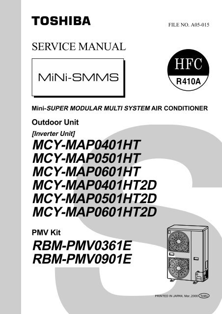
MCY-MAP0401HT MCY-MAP0501HT MCY-MAP0601HT ... - Toshiba
MCY-MAP0401HT MCY-MAP0501HT MCY-MAP0601HT ... - Toshiba
MCY-MAP0401HT MCY-MAP0501HT MCY-MAP0601HT ... - Toshiba
- No tags were found...

Create successful ePaper yourself
Turn your PDF publications into a flip-book with our unique Google optimized e-Paper software.
WARNINGS ON REFRIGERANT LEAKAGECheck of Concentration LimitThe room in which the air conditioner is to beinstalled requires a design that in the event ofrefrigerant gas leaking out, its concentration will notexceed a set limit.The refrigerant R410A which is used in the airconditioner is safe, without the toxicity or combustibilityof ammonia, and is not restricted by laws to be imposedwhich protect the ozone layer. However, since itcontains more than air, it poses the risk of suffocation ifits concentration should rise excessively. Suffocationfrom leakage of R410A is almost non-existent. With therecent increase in the number of high concentrationbuildings, however, the installation of multi airconditioner systems is on the increase because of theneed for effective use of floor space, individual control,energy conservation by curtailing heat and carryingpower etc.Most importantly, the multi air conditioner system is ableto replenish a large amount of refrigerant compared withconventional individual air conditioners. If a single unit ofthe multi conditioner system is to be installed in a smallroom, select a suitable model and installation procedureso that if the refrigerant accidentally leaks out, itsconcentration does not reach the limit (and in the eventof an emergency, measures can be made before injurycan occur).In a room where the concentration may exceed the limit,create an opening with adjacent rooms, or installmechanical ventilation combined with a gas leakdetection device.The concentration is as given below.Total amount of refrigerant (kg)Min. volume of the indoor unit installed room (m³)≤ Concentration limit (kg/m³)The concentration limit of R410A which is used in multiair conditioners is 0.3kg/m³.NOTE 1 :If there are 2 or more refrigerating systems in a singlerefrigerating device, the amounts of refrigerant shouldbe as charged in each independent device.e.g., chargedamount (10kg)Outdoor unite.g.,charged amount (15kg)Room A Room B Room C Room D Room E Room FIndoor unitFor the amount of charge in this example:The possible amount of leaked refrigerant gas inrooms A, B and C is 10kg.The possible amount of leaked refrigerant gas inrooms D, E and F is 15kg.ImportantNOTE 2 :The standards for minimum room volume are as follows.(1) No partition (shaded portion)(2) When there is an effective opening with the adjacentroom for ventilation of leaking refrigerant gas(opening without a door, or an opening 0.15% orlarger than the respective floor spaces at the top orbottom of the door).Outdoor unitRefrigerant pipingIndoor unit(3) If an indoor unit is installed in each partitioned roomand the refrigerant piping is interconnected, thesmallest room of course becomes the object. Butwhen a mechanical ventilation is installedinterlocked with a gas leakage detector in thesmallest room where the density limit is exceeded,the volume of the next smallest room becomes theobject.VerysmallroomSmallroomMediumroomLarge roomRefrigerant pipingMechanical ventilation device - Gas leak detectorOutdoor unitIndoor unitNOTE 3 :The minimum indoor floor area compared with theamount of refrigerant is roughly as follows:(When the ceiling is 2.7m high)m² 35Min. indoor floor area40302520151050Range below thedensity limitof 0.3 kg/m³(countermeasuresnot needed)Range abovethe density limitof 0.3 kg/m³(countermeasuresneeded)10 20 30Total amount of refrigerantkg
CONTENTSSAFETY CAUTION ............................................................................................ 41. DESIGN METHODS ................................................................................ 102. WIRING DIAGRAM ................................................................................. 183. PARTS RATING ...................................................................................... 334. REFRIGERANT PIPING SYSTEMATIC DRAWING ............................... 515. SWITCH (SW08) SET UP OF THE OUTDOOR UNIT ............................. 546. CONTROL OUTLINE .............................................................................. 557. APPLIED CONTROL .............................................................................. 638. PMV KIT OUT LINE ................................................................................ 779. TEST OPERATION ................................................................................. 7910. TROUBLESHOOTING .......................................................................... 10811. CONFIGURATION OF CONTROL CIRCUIT ........................................ 15212. BACKUP OPERATIONS (EMERGENCY OPERATION)....................... 16613. REPLACING COMPRESSOR............................................................... 16714. REPLACING PROCEDURE OF PARTS ............................................... 16815. P.C. BOARD .......................................................................................... 18216. EXPLODED VIEWS AND PARTS LIST ................................................. 1883
SAFETY CAUTIONThe important contents concerned to the safety are described on the product itself and on this Service Manual.Please read this Service Manual after understanding the described items thoroughly in the following contents(Indications/Illustrated marks), and keep them.[Explanation of indications]IndicationDANGERWARNINGCAUTIONExplanationIndicates contents assumed that an imminent danger causing a death or serious injury ofthe repair engineers and the third parties when an incorrect work has been executed.Indicates possibilities assumed that a danger causing a death or serious injury of therepair engineers, the third parties, and the users due to troubles of the product after workwhen an incorrect work has been executed.Indicates contents assumed that an injury or property damage (∗) may be caused on therepair engineers, the third parties, and the users due to troubles of the product after workwhen an incorrect work has been executed.∗ Property damage : Enlarged damage concerned to property, furniture, and domestic animal/pet[Explanation of illustrated marks]MarkExplanationIndicates prohibited items (Forbidden items to do)The sentences near an illustrated mark describe the concrete prohibited contents.Indicates mandatory items (Compulsory items to do)The sentences near an illustrated mark describe the concrete mandatory contents.Indicates cautions (including danger/warning)The sentences or illustration near or in an illustrated mark describe the concrete cautious contents.[Confirmation of warning label on the main unit]Confirm that labels are indicated on the specified positions(Refer to the Parts disassembly diagram (Outdoor unit).)If removing the label during parts replace, stick it as the original.DANGERTurn off breaker.Execute dischargebetween terminals.Turn “OFF” the breaker before removing the front panel and cabinet, otherwise an electricshock is caused by high voltage resulted in a death or injury.During operation, a high voltage with 400V or higher of circuit (∗) at secondary circuit of the highvoltagetransformer is applied.If touching a high voltage with the naked hands or body, an electric shock is caused even if using anelectric insulator.∗ : For details, refer to the electric wiring diagram.When removing the front panel or cabinet, execute short-circuit and discharge between highvoltagecapacitor terminals.If discharge is not executed, an electric shock is caused by high voltage resulted in a death or injury.After turning off the breaker, high voltage also keeps to apply to the high-voltage capacitor.Do not turn on the breaker under condition that the front panel and cabinet are removed.An electric shock is caused by high voltage resulted in a death or injury.Prohibition4
WARNINGCheck earth wires.Prohibition of modification.Use specified parts.Do not bring a childclose to the equipment.Insulating measuresNo fireRefrigerantAssembly/CablingBefore troubleshooting or repair work, check the earth wire is connected to the earthterminals of the main unit, otherwise an electric shock is caused when a leak occurs.If the earth wire is not correctly connected, contact an electric engineer for rework.Do not modify the products.Do not also disassemble or modify the parts. It may cause a fire, electric shock or injury.For spare parts, use those specified (*).If unspecified parts are used, a fire or electric shock may be caused.∗: For details, refer to the parts list.Before troubleshooting or repair work, do not bring a third party (a child, etc.) exceptthe repair engineers close to the equipment.It causes an injury with tools or disassembled parts.Please inform the users so that the third party (a child, etc.) does not approach the equipment.Connect the cut-off lead cables with crimp contact, etc, put the closed end sideupward and then apply a water-cut method, otherwise a leak or production of fire iscaused at the users’ side.When repairing the refrigerating cycle, take the following measures.1) Be attentive to fire around the cycle. When using a gas stove, etc, be sure to put out firebefore work; otherwise the oil mixed with refrigerant gas may catch fire.2) Do not use a welder in the closed room. When using it without ventilation, carbonmonoxide poisoning may be caused.3) Do not bring inflammables close to the refrigerant cycle, otherwise fire of the welder maycatch the inflammables.(For more details, please refer Page 7 to Page 9)This air conditioner adopts a new HFC type refrigerant (R410A) which does not deplete theozone layer.Check the used refrigerant name and use tools and materials of the parts whichmatch with it.For the products which use R410A refrigerant, the refrigerant name is indicated at aposition on the outdoor unit where is easy to see. To prevent miss-charging, the route of theservice port is changed from one of the former R22.For an air conditioner which uses R410A, never use other refrigerant than R410A.For an air conditioner which uses other refrigerant (R22, etc.), never use R410A.If different types of refrigerant are mixed, abnormal high pressure generates in the refrigeratingcycle and an injury due to breakage may be caused.Do not charge refrigerant additionally.If charging refrigerant additionally when refrigerant gas leaks, the refrigerant composition inthe refrigerating cycle changes resulted in change of air conditioner characteristics orrefrigerant over the specified standard amount is charged and an abnormal high pressure isapplied to the inside of the refrigerating cycle resulted in cause of breakage or injury.Therefore if the refrigerant gas leaks, recover the refrigerant in the air conditioner, executevacuuming, and then newly recharge the specified amount of liquid refrigerant. In this time,never charge the refrigerant over the specified amount.When recharging the refrigerant in the refrigerating cycle, do not mix the refrigerantor air other than R410A into the specified refrigerant.If air or others is mixed with the refrigerant, abnormal high pressure generates in therefrigerating cycle resulted in cause of injury due to breakage.After installation work, check the refrigerant gas does not leak.If the refrigerant gas leaks in the room, poisonous gas generates when gas touches to firesuch as fan heater, stove or cocking stove though the refrigerant gas itself is innocuous.Never recover the refrigerant into the outdoor unit.When the equipment is moved or repaired, be sure to recover the refrigerant with recoveringdevice. The refrigerant cannot be recovered in the outdoor unit; otherwise a seriousaccident such as breakage or injury is caused.After repair work, surely assemble the disassembled parts, and connect and lead theremoved cables as before. Perform the work so that the cabinet or panel does notcatch the inner cables.If incorrect assembly or incorrect cable connection was done, a disaster such as a leak orfire is caused at user’s side.5
WARNINGInsulator checkVentilationBe attentive toelectric shockCompulsionAfter the work has finished, be sure to use an insulation tester set (500V mugger) tocheck the resistance is 2MΩ or more between the charge section and the non-chargemetal section (Earth position).If the resistance value is low, a disaster such as a leak or electric shock is caused at user’sside.When the refrigerant gas leaks during work, execute ventilation.If the refrigerant gas touches to a fire, poisonous gas generates. A case of leakage of therefrigerant and the closed room full with gas is dangerous because a shortage of oxygenoccurs. Be sure to execute ventilation.When checking the circuit inevitably under condition of the power-ON, use rubbergloves and others not to touch to the charging section.If touching to the charging section, an electric shock may be caused.When the refrigerant gas leaks, find up the leaked position and repair it surely.If the leaked position cannot be found up and the repair work is interrupted, pump-downand tighten the service valve, otherwise the refrigerant gas may leak into the room.The poisonous gas generates when gas touches to fire such as fan heater, stove or cockingstove though the refrigerant gas itself is innocuous.When installing equipment which includes a large amount of charged refrigerant suchas a multi air conditioner in a sub-room, it is necessary that the density does not thelimit even if the refrigerant leaks.If the refrigerant leaks and exceeds the limit density, an accident of shortage of oxygen iscaused.For the installation/moving/reinstallation work, follow to the Installation Manual.If an incorrect installation is done, a trouble of the refrigerating cycle, water leak, electricshock or fire is caused.After repair work has finished, check there is no trouble.If check is not executed, a fire, electric shock or injury may be caused. For a check, turn offthe power breaker.Check after rerairCheck after reinstallationAfter repair work (installation of front panel and cabinet) has finished, execute a testrun to check there is no generation of smoke or abnormal sound.If check is not executed, a fire or an electric shock is caused. Before test run, install thefront panel and cabinet.Check the following items after reinstallation.1) The earth wire is correctly connected.2) The power cord is not caught in the product.3) There is no inclination or unsteadiness and the installation is stable.If check is not executed, a fire, an electric shock or an injury is caused.CAUTIONPut on glovesCooling checkBe sure to put on gloves (∗) during repair work.If not putting on gloves, an injury may be caused with the parts, etc.(∗) Heavy gloves such as work glovesWhen the power was turned on, start to work after the equipment has beensufficiently cooled.As temperature of the compressor pipes and others became high due to cooling/heatingoperation, a burn may be caused.6
• New Refrigerant (R410A)1. Safety Caution Concerned to New RefrigerantThe pressure of R410A is high 1.6 times of that of the former refrigerant (R22). Accompanied with change ofrefrigerant, the refrigerating oil has been also changed. Therefore, be sure that water, dust, the formerrefrigerant or the former refrigerating oil is not mixed into the refrigerating cycle of the air conditioner withnew refrigerant during installation work or service work. If an incorrect work or incorrect service is performed,there is a possibility to cause a serious accident. Use the tools and materials exclusive to R410A topurpose a safe work.2. Cautions on Installation/Service1) Do not mix the other refrigerant or refrigerating oil.For the tools exclusive to R410A, shapes of all the joints including the service port differ from those of theformer refrigerant in order to prevent mixture of them.2) As the use pressure of the new refrigerant is high, use material thickness of the pipe and tools which arespecified for R410A.3) In the installation time, use clean pipe materials and work with great attention so that water and others donot mix in because pipes are affected by impurities such as water, oxide scales, oil, etc.Use the clean pipes.Be sure to brazing with flowing nitrogen gas. (Never use gas other than nitrogen gas.)4) For the earth protection, use a vacuum pump for air purge.5) R410A refrigerant is azeotropic mixture type refrigerant. Therefore use liquid type to charge the refrigerant.(If using gas for charging, composition of the refrigerant changes and then characteristics of the airconditioner change.)3. Pipe MaterialsFor the refrigerant pipes, copper pipe and joints are mainly used. It is necessary to select the most appropriatepipes to conform to the standard. Use clean material in which impurities adhere inside of pipe or joint to aminimum.1) Copper pipeThe pipe thickness, flare finishing size, flare nut and others differ according to a refrigerant type.When using a long copper pipe for R410A, it is recommended to select “Copper or copper-base pipe withoutseam” and one with bonded oil amount 40mg/10m or less. Also do not use crushed, deformed, discolored(especially inside) pipes. (Impurities cause clogging of expansion valves and capillary tubes.)Use the flare nuts which are attached to the air conditioner unit.2) JointThe flare joint and socket joint are used for joints of the copper pipe. The joints are rarely used for installationof the air conditioner. However clear impurities when using them.7
4. Tools(1) Required Tools for R410AMixing of different types of oil may cause generation of sludge, clogging of capillary, etc.Accordingly, the tools to be used are classified into the following three types.1) Tools exclusive for R410A (Those which cannot be used for conventional refrigerant (R22))2) Tools exclusive for R410A, but can be also used for conventional refrigerant (R22)3) Tools commonly used for R410A and for conventional refrigerant (R22)The table below shows the tools exclusive for R410A and their interchangeability.Tools exclusive for R410A (The following tools for R410A are required.)Tools whose specifications are changed for R410A and their interchangeabilityR410Aair conditioner installationConventional airconditioner installationNo.Used toolUsageExistence ofnew equipmentfor R410AWhether conventionalequipment can beusedWhether new equipmentcan be used withconventional refrigerantFlare toolPipe flaringYes*(Note 1)Yes‚Copper pipe gauge foradjusting projectionmarginFlaring by conventionalflare toolYes*(Note 1)*(Note 1)ƒTorque wrenchConnection of flare nutYesNoNo„…Gauge manifoldCharge hoseEvacuating, refrigerantcharge, run check, etc.YesNoNo†Vacuum pump adapterVacuum evacuatingYesNoYes‡Electronic balance forrefrigerant chargingRefrigerant chargeYesYesYesˆRefrigerant cylinderRefrigerant chargeYesNoNo‰Leakage detectorGas leakage checkYesNoYesŠCharging cylinderRefrigerant charge(Note 2)NoNo(Note 1) When flaring is carried out for R410A using the conventional flare tools, adjustment of projectionmargin is necessary. For this adjustment, a copper pipe gauge, etc. are necessary.(Note 2) Charging cylinder for R410A is being currently developed.General tools (Conventional tools can be used.)In addition to the above exclusive tools, the following equipments which serve also for R22 are necessaryas the general tools.1) Vacuum pumpUse vacuum pump byattaching vacuum pump adapter.2) Torque wrench3) Pipe cutter4) Reamer5) Pipe bender6) Level vial7) Screwdriver (+, –)8) Spanner or Monkey wrench9) Hole core drill10) Hexagon wrench (Opposite side 4mm)11) Tape measure12) Metal sawAlso prepare the following equipments for other installation method and run check.1) Clamp meter2) Thermometer3) Insulation resistance tester (Megger)4) Electroscope (Volt meter)8
5. Recharge of RefrigerantWhen recharge of the refrigerant is required, charge the new refrigerant with the specified amount in theprocedure as described below.Recover the refrigerant and check there is no refrigerant in theequipment.Connect the charge hose to the packed valve service ports at gasside, liquid side of the outdoor unit.Connect the charge hose to vacuum pump adaptor.Open the packed valves fully at liquid and gas sides, and then returnthe valve at gas side a little to the closed side.Leave it as it is for 1 to 2 minutes and check the indicatorof the compound gauge does not return.Set the refrigerant cylinder on the electronic balance,connect the charge hose to connecting ports of thecylinder and the gauge manifold, and then charge theliquid refrigerant from the service port at liquid side.(Shield with the gauge manifold so that refrigerant doesnot flow to gas side.)Open fully PMV of the outdoor unit.• Turn on power of the outdoor unit.• Short CN30 on I/F P.C. board of the outdoor unit.• Turn off power of the outdoor unit within 2 minutes after shorting CN30.Open fully the handle on the Low side of the gauge manifold, andthen turn on the power of vacuum pump for vacuuming.When the pressure has lowered until indication of the compoundgauge pointed –0.1MPa (–76cmHg), open fully the handle Low andturn off the power of vacuum pump.Never charge the refrigerant over the specified amount.‚ Do not charge the additional refrigerant.If charging refrigerant additionally when refrigerant gasleaks, the refrigerant composition in the refrigerating cyclechanges resulted in change of air conditioner characteristicsor refrigerant over the specified standard amount ischarged and an abnormal high pressure is applied to theinside of the refrigerating cycle resulted in cause ofbreakage or injury.Connected toindoor unitMainpipeBrazedFullytightenedConnected to otherterminal unitsValve fully closed(gas side)Center unitValve fully closed(liquid side)LowpressuregaugeServiceport Ø6.4Copper pipeService portVLHighpressuregaugeVHGaugemanifoldReducingvalveNitrogengasØ6.4Copper pipe4mm-hexagonal wrench is required.Set the equipment so that liquid refrigerant can be charged.‚ When using a cylinder with siphon pipe, liquid can be charged without inverting the cylinder.[ Cylinder with siphon ] [ Cylinder without siphon ]Gauge manifoldGauge manifoldOUTDOOR unitOUTDOOR unitSiphonRefrigerantcylinderRefrigerantcylinderElectronicbalanceElectronicbalanceR410A refrigerant is consisted with HFC mixed refrigerant.Therefore if the refrigerant gas is charged, the compositionof the charged refrigerant changes and characteristics ofthe equipment changes.6. Environmental concernUse “Vacuum pump method” for an air purge (Discharge of air in the connecting pipe) in installation time.• Do not discharge flon gas into the air to protect the earth environment.• Using the vacuum pump method, clear the remaining air (Nitrogen, etc.) in the unit. If the air remains, thepressure in the refrigerating cycle becomes abnormally high and an injury could occur through failure ofthe product.9
1. DESIGN METHODS1-1. System Overview1-1-1. Outdoor UnitsCorresponding HPInverter unit4HP 5HP 6HPModel nameHeat pump (50Hz)Heat pump (60Hz)<strong>MCY</strong>-<strong>MAP0401HT</strong> <strong>MCY</strong>-<strong>MAP0501HT</strong> <strong>MCY</strong>-<strong>MAP0601HT</strong><strong>MCY</strong>-<strong>MAP0401HT</strong>2D <strong>MCY</strong>-<strong>MAP0501HT</strong>2D <strong>MCY</strong>-<strong>MAP0601HT</strong>2DCooling capacity (kW) ∗1Heating capacity (kW) ∗1No.of connectable indoor units12.1 14.0 15.512.5 16.0 18.06 8 9∗1 Rated conditionsCooling:Indoor air temperature 27°C DB/19°C WB, Outdoor air temperature 35°C DBHeating:Indoor air temperature 20°C DB, Outdoor air temperature 7°C DB/6°C WBAllocation standard of model name<strong>MCY</strong>- M APH T 2DNo mark : Power supply specification, 1Ø/220/230/240V (50Hz)2D : Power supply specification, 1Ø/220V, 60HzT : Inverter unitH : Heat pumpDevelopment numberCapacity rank HP × 10R410AM : Individual unitMulti Compact type10
1-1-2. Indoor UnitsTypeAppearanceModel nameCapacityrankCapacitycodeCoolingcapacity (kW)Heatingcapacity (kW)PMV KitMMU-AP0091H009 type1.002.83.2——MMU-AP0121H012 type1.253.64.0——MMU-AP0151H015 type1.704.55.0——4-way Air DischargeCassette TypeMMU-AP0181HMMU-AP0241HMMU-AP0271H018 type024 type027 type2.002.503.005.67.18.06.38.09.0——————MMU-AP0301H030 type3.209.010.0——MMU-AP0361H036 type4.0011.212.5——MMU-AP0481H048 type5.0014.016.0——MMU-AP0071MH007 type0.802.22.5AvailableCompact 4-wayAir Discharge(600 × 600) TypeMMU-AP0091MHMMU-AP0121MHMMU-AP0151MH009 type012 type015 type1.001.251.702.83.64.53.24.05.0AvailableAvailableAvailableMMU-AP0181MH018 type2.005.66.3AvailableMMU-AP0071WH007 type0.802.22.5——MMU-AP0091WH009 type1.002.83.2——MMU-AP0121WH012 type1.253.64.0——2-way Air DischargeCassette TypeMMU-AP0151WHMMU-AP0181WH015 type018 type1.702.004.55.65.06.3————MMU-AP0241WH024 type2.507.18.0——MMU-AP0271WH027 type3.008.09.0——MMU-AP0301WH030 type3.209.010.0——MMU-AP0071YH007 type0.802.22.5AvailableMMU-AP0091YH009 type1.002.83.2Available1-way Air DischargeCassette TypeMMU-AP0121YHMMU-AP0152SH012 type015 type1.251.703.64.54.05.0AvailableAvailableMMU-AP0182SH018 type2.005.66.3AvailableMMU-AP0242SH024 type2.507.18.0AvailableMMD-AP0071BH007 type0.802.22.5——MMD-AP0091BH009 type1.002.83.2——MMD-AP0121BH012 type1.253.64.0——MMD-AP0151BH015 type1.704.55.0——Concealed DuctStandard TypeMMD-AP0181BHMMD-AP0241BH018 type024 type2.002.505.67.16.38.0————MMD-AP0271BH027 type3.008.09.0——MMD-AP0301BH030 type3.209.010.0——MMD-AP0361BH036 type4.0011.212.5——MMD-AP0481BH048 type5.0014.016.0——MMD-AP0071SPH007 type0.802.22.5AvailableMMD-AP0091SPH009 type1.002.83.2AvailableSlim Duct TypeMMD-AP0121SPH012 type1.253.64.0AvailableMMD-AP0151SPH015 type1.704.55.0AvailableMMD-AP0181SPH018 type2.005.66.3AvailableMMD-AP0181H018 type2.005.66.3——Concealed DuctHigh StaticPressure TypeMMD-AP0241HMMD-AP0271HMMD-AP0361H024 type027 type036 type2.503.004.007.18.011.28.09.010.0——————MMD-AP0481H048 type5.0014.016.0——MMC-AP0151H015 type1.704.55.0——MMC-AP0181H018 type2.005.66.3——Under Ceilling TypeMMC-AP0241HMMC-AP0271H024 type027 type2.503.007.18.08.09.0————MMC-AP0361H036 type4.0011.212.5——MMC-AP0481H048 type5.0014.016.0——11
TypeAppearanceModel nameCapacityrankCapacitycodeCoolingcapacity (kW)Heatingcapacity (kW)PMV KitMMK-AP0071H007 type0.802.22.5AvailableMMK-AP0091H009 type1.002.83.2AvailableHigh Wall Type(1 series)MMK-AP0121HMMK-AP0151H012 type015 type1.251.703.64.54.05.0AvailableAvailableMMK-AP0181H018 type2.005.66.3AvailableMMK-AP0241H024 type2.507.18.0AvailableMMK-AP0072H007 type0.802.22.5AvailableHigh Wall Type(2 series)MMK-AP0092H009 type1.002.83.2AvailableMMK-AP0122H012 type1.253.64.0AvailableMML-AP0071H007 type0.802.22.5AvailableMML-AP0091H009 type1.002.83.2AvailableFloor StandingCabinet TypeMML-AP0121HMML-AP0151H012 type015 type1.251.703.64.54.05.0AvailableAvailableMML-AP0181H018 type2.005.66.3AvailableMML-AP0241H024 type2.507.18.0AvailableMML-AP0071BH007 type0.802.22.5——MML-AP0091BH009 type1.002.83.2——Floor StandingConcealed TypeMML-AP0121BHMML-AP0151BH012 type015 type1.251.703.64.54.05.0————MML-AP0181BH018 type2.005.66.3——MML-AP0241BH024 type2.507.18.0——MMF-AP0151H015 type1.704.55.0——MMF-AP0181H018 type2.005.66.3——Floor Standing TypeMMF-AP0241HMMF-AP0271H024 type027 type2.503.007.18.08.09.0————MMF-AP0361H036 type4.0011.210.0——MMF-AP0481H048 type5.0014.016.0——Allocation standard of model nameMM - AP H -C : China modelH : Heat pump typeM : Compact 4-way Cassete TypeW : 2-way Cassette TypeS : 1-way Cassette TypeY : Small sized 1-way Cassette TypeB : Built-in Type (Built-in Duct Type) (Floor concealed type)SP(S) : Slim Duct TypeDevelopment series No.Based on the cooling capacity (Btu/h) /1,000R410AU : Cassette TypeC : Under Ceiling TypeD : Duct TypeK : High Wall TypeL : Floor Type (Cabinet type) (Concealed type)F : Floor Standing TypeMM : Modular Multi type12
1-1-3. Branching Joints and Headers *1Model nameUsageAppearanceY-shape branching jointRBM-BY53ERBM-BY103EIndoor unit capacity code (*2) :Total below 6.4Indoor unit capacity code (*2) :Total 6.4 or more and below 7.84-branching headerRBM-HY1043EIndoor unit capacity code (*2) :Total below 7.88-branching headerRBM-HY1083EIndoor unit capacity code (*2) :Total below 7.8*1 If total capacity code value of indoor unit exceeds that of outdoor unit, apply code of outdoor unit.*2 “Capacity code” can be obtained. (capacity code is not actual capacity)*3 When using Y-shape branching joint for 1st branching, select according to the capacity code of outdoor unit.1-1-4. PMV KitModel nameIndoor unit capacity typeAppearanceRBM-PMV0361E007, 009, 012 typeRBM-PMV0901E015, 018, 024 type13
1-1-5. Remote ControllerNameModelnameAppearanceApplicationFunctionWired remote controllerRBC- AMT31EConnected to indoor unitWired remotecontrollerWired remotecontrollerIn case of control by( )2 remote controllers• Start / Stop• Mode Change• Temperature setting• Fan speed• Timer function1) On or off elapsed timer with30 minutes increments.Automatic off function.2) Weekly when combined withRBC-EXW21E2 weekly scheduleoperation can be operated.• Filter dirty indicatorDisplays automatically maintenance timeof indoor filter by flashes.• Self-diagnosis function. Pressing“CHECK” button displays status code.• Control by 2 remote controllers is available.Two remote controllers can be connectedto one indoor unit.The indoor unit can be separatelyoperated from a different location.Simple wired remote controllerRBC- AS21E2TESTSETTINGûCûFConnected to indoor unitSimple remote controller• Start / Stop• Temperature setting• Change of air flow• Check code displayWireless remote controller kitTCB- AX21U(W)-E2 RBC-AX22CE2 TCB-AX21E2• Start / Stop• Mode change• Temperature setting• Change of air flow• Timer functionOn or off timer operation, setting in 30minutes increments.Automatic Off function.• Control by 2 remote controllers is available.Two wireless remote controllers canoperate one indoor unit.The indoor unit can be separatelyoperated from a different location.• Check code displayTCB-AX21U(W)-E2(for 4-way air discharge cassette)RBC-AX22CE2 (for under ceiling)TCB-AX21-E2 (for other units except forthe concealed duct high static pressure)14
NameModelnameAppearanceApplicationPerformanceCentral remote controllerTCB- SC642TLE2ALL ZONEZONEGROUP1234UNIT No. TESTSET DATASETTING R.C. No.SELECT ZONECL SETGROUPCODENo.Connected to outdoor unitor indoor unitOutdoor unitCentralremote controllerIndividual control up to 64 indoor units.Individual control for max. 64 indoorunits divided into 4 zones.(Up to 16 indoor units for each zone)Up to 16 outdoor units are connectable.Four selectable central control settingsto restrict individual remote controlleroperations.Setting for one of 1 to 4 zones isavailable.Can be used with other central controldevices (Up to 10 central controldevices with in one control circuit)Two selectable control modes(Central controller mode.Remote controller mode)Setting of simultaneous ON/OFF 3times for each day of the weekcombined with a weekly timer.CentralremotecontrollerIndoorremote controllerConnected to outdoor unitor indoor unit• Individual control up to 16 indoorunits.• Setting of simultaneous ON-OFF 3times for each day of the week whencombined with a weekly timer.• Connected to 2 remote controllers ispossible.Outdoor unitON- OFF controllerTCB- CC163TLE2ON-OFFcontrollerIndoor unitON-OFFcontrollerIndoorremote controller15
NameModelnameAppearanceApplicationPerformanceConnected to centralremote controller orwired remote controllerWeekly schedule operation1) Setting different start / stop time foreach day of the week2) ON / OFF can be set 3 times a day.ONOFF ON OFF ON OFF8:00 12:00 13:00 18:00 19:00 21:00Weekly timerRBC- EXW21E2PROGRAM1PROGRAM2PROGRAM3WEEKLY TIMERSuMoTuWeTh Fr SaERRORWiredremote controllerOutdoor unitWeeklytimer3) “CHECK“ “PROGRAM” “DAY” buttoncopying of settings easy.4) Two different schedules for a weekcan be specified.(Summer schedule and winterschedule, etc.)5) “CANCEL” “DAY” button enablesholiday setting.6) If power supply fails, the settingcontents are stored in the memoryfor 100 hours.Centralremote controllerWeeklytimer16
n Remote controllersNameWired remote controllerSimple wired remote controllerWeekly timerSET DATA SETTING TESTHUNIT No.R.C.No.CODE No.TESTSETTING˚C˚FPROGRAM1PROGRAM2SuMoTuWeTh Fr SaERRORPROGRAM3AppearanceTEMP.ON / OFFWEEKLY TIMERTIMER SETFANMODETIMESWING/FIXVENTFILTERRESET TESTSETCLUNITModel nameRBC-AMT31ERBC-AS21E2RBC-EXW21E2NameWireless remote controller kitReceiver sectionReceiver sectionmounted separatelyAppearanceADR ADR ADRReceiver sectionModel nameRBC-AX21U (W)-E2RBC-AX22CE2TCB-AX21E2Type4-way Air DischargeCassette typeUnder Ceiling type1-way Air Discharge Cassettetype (MMU-AP✽✽✽2SH Series)Separate sensor typeNameCentral remote controllerON, OFF controllerALL ZONEZONEGROUP1234UNIT No.TESTCODENo.AppearanceSET DATASETTINGR.C.No.SELECTZONEGROUPCLSETModel nameTypeTCB-SC642TLE264 system center controllerTCB-CC163TLE2—17
18Indoor unitR(L) S(N)Earth screwSymbolFMTATC1TCJTC2LM1, LM2DMFSRY302PMVPower supplySingle phase220-240V 50Hz220V 60HzDMFlow selectorunit earthscrewREDWHIClosed endconnectorParts nameFan motorIndoor temp sensorTemp sensorTemp sensorTemp sensorLouver motorDrain pump motorFloat switchDrain control relayPulse Motor ValveCN68(BLU)123CN304(GRY)RED1CN67(BLK)23WHIBLKCN66(WHI)CN44(BLN)1231231231212RY302RY303FuseT6.3A250V~P301CN50(WHI)1 2 35 4 3 2 1 CN3345 4 3 2 1 (BLU)CN32(WHI)(Fandrive)FM~ +~ –PMV6 4 3 1 2 56 4 3 1 2 51 2 3 4 5 CN333 1 2 3 4 5 61 2 3 4 5 (WHI) 1 2 3 4 5 6Motor drivecircuitCN61(YEL)1 2 3 4 5FuseT3.15A250V~CN60(WHI)1 2(Option)CN82(BLU)DC20VDC15VDC12VDC7VCN81(BLK)4 5 1 2 T10 6 3 4 5 6 1 2 3 4 51. indicates the terminal block, letter at insideindicates the terminal number.2. A dotted line and broken line indicate the wiring at site.3. indicates the control P.C. board.RED : REDWHI : WHITEYEL : YELLOWBLU : BLUEBRN : BROWNColor identificationBLK : BLACKGRY : GRAYPNK : PINKORN : ORANGEGRN : GREENPowersupplycircuitU1 U2Outdoor unitU1U2ALM21 2 3 4 51 2 3 4 51 2 3 4 51 2 3 4 51 2 3 4 51 2 3 4 5Indoor control P.C. boardMCC-1402BCN1(WHI)1 21 2Wired remotecontrollerCN40(BLU)1 21 2BLUBLUWHIBLKCN41(BLU)1 2 31 2 3BLKBLKBLKWHICN001(WHI)1 21 2Adaptor for wirelessremote controllerCN309(YEL)CN01(WHI)3 32 21 1CN02(BLU)LM11 2 3 4 51 2 3 4 5CN33(WHI)1 2 31 2 31 21 21 2 CN031 2 (RED)X YTR3 13 2 1CN104(YEL)CN102(RED)CN101(BLK)CN100(BRN)CN80(GRN)CN73(RED)CN20 CN70(BLU) (WHI)1 2 3 4 5Network adaptor(Option)NetworkadaptorP.C. boardMCC-1401FSCN34(RED)1212121212121 12 23 312PNL31212EXCTTATCJTC2Filter inputTC1Model: MMU-AP0091H, AP0121H, AP0151H, AP0181H, AP0241H,MMU-AP0271H, AP0301H, AP0361H, AP0481H, AP0561H,MMU-AP0071MH, AP0091MH, AP0121MH, AP0151MH, AP0181MH2-1-1. 4-way Air Discharge Cassette Type2-1. Indoor Unit2. WIRING DIAGRAM
20ColorindicationRED : REDWHI : WHITEYEL : YELLOWBLU : BLUEBLK : BLACKGRY : GRAYPNK : PINKORN : ORANGEBRW : BROWNGRN : GREENIndoor unitEarth screwREDWHIR(L) S(N)REDPower supplySingle phase220-240V 50Hz220V 60HzFMWHIRCFlow selectorunit earthscrewClosed endconnectorBLU1 12 23 34 45 56 6CN301(BLK)HeaterCN304(GRY)CN309(YEL)AC IN123123CN066(WHI)TRU112312312312Line FilterOutdoorunitCN067(BLK)CN044(BRW)1 21 2BLUBLUU2U1CN040(BLU)1 21 2BLUBLUU2RY004BLKFuseT5.0AABLKBCN041(BLU)1 2 31 3XCN1(WHI)1 21 2Remote controllerFANCN083(WHI)YAI-NETcentral controlterminalRED9 8 7 69 8 7 6RY007BLKMCC-1401CN01(WHI)1 12 2CN03(RED)ORNCN050(WHI)1 2 3 4 51 21 23 2 13 2 15 4 3 2 15 4 3 2 1RY006NetworkadaptorP.C. boardBLURY005Networkadaptor(Option)CN02(BLU)YELH M L ULRY002CN074(WHI)DM1 2 31 2 31 2 31 2 31 2 31 2 3DP(BLU)CN068RY001LM2 12 11 2 31 2 3Power supplycircuit1 2 3 4 5 61 2 3 4 5 61 2 3 4 5 61 2 3 4 5 6Sub P.C. boardMCC-15201 2 3 4 5 61 2 3 4 5 6LM(GRN)CN033Indoor control P.C. boardCN075(WHI)CN02(YEL)CN01(WHI)TR2 12 11 2 31 2 3FSCN061(YEL)FS(RED)CN0301. indicates the terminal block, letter at insideindicates the terminal number.2. A dotted line and broken line indicate the wiring at site.3. indicates the control P.C. board.CN032(WHI)6 4 36 4 31 2 31 2 3PMVCN104(YEL)CN102(RED)CN101(BLK)CN100(BRW)CN080(GRN)CN073(RED)CN070(WHI)CN081(BLK)CN060(WHI)1 2 3 4 5 6 1 2 1 2 3 4 5 6Fan drive OptionSymbolFMRCTRLMTATC1,TCJRY001RY002RY004RY005~007FSDMPMV1 2 51 2 54 5 64 5 6PMV(BLU)CN08212121212121 12 23 312 PNL3121212345EXCT12TATCJFilterTC1Parts nameFan motorRunning capacitorPower transformerLouver motorIndoor temp sensorTemp sensorLouver motor control relayDrain pump control relayHeater control relayFan motor control relayFloat switchDrain pump motorPulse Motor ValveModel: MMU-AP0071YH, AP0091YH, AP0121YH2-1-3. 1-way Air Discharge Cassette Type (Compact type)
21Indoor unitearth screwR(L) S(N)REDWHIPower supplysingle phase220-240V 50Hz220V 60HzFMTATC1TCJTC2LMDMFSRY302PMVTRFlow selector unitearth screwClosed-endconnectorU1U2OutdoorunitSymbolU1U2AABWiredremotecontrollerParts nameFan motorIndoor temp sensorTemp sensorTemp sensorTemp sensorLouver motorDrain pump motorFloat switshDrain control relayPulse motor valveTransformerBWHIWHIBLKBLK1 21 2CN001(WHI)Adapter forwireless remotecontrollerColorindicationRED: REDWHI : WHITEYEL : YELLOWBLU : BLUEBLK : BLACKGRY: GRAYPNK : PINKORN: ORANGEBRN: BRWNGRN: GREENTR1 123 3MCC-1401AI-NETCN02(BLU)Network adapter(Option)RED1 21 2CN01(WHI)CN03(RED)11WHI22X YDMCN68(BLU)CN304(GRY)CN67(BLK)BLUBLUBLKBLK1 13 3131 13 3BLK121 21 21 123 3CN334(WHI)RY302RY303P301CN66(WHI)CN40(BLU)CN41(BLU)5 4 15 4 3 2 1FuseT6.3A 250V~1133CN309(YEL)11CN50(WHI)FM331 2 3 4 555Motor drivecircuitCN333(WHI)66CN061(YEL)44PMV331122551 2 3 4 5 61 2 3 4 5 6CN82(BLU)FuseT3.15A250V~CN32(WHI)High ceiling setup1 21 2 1 2 1 2CN112(WHI)PowersupplycircuitCN60(WHI)CN111(WHI)DC20VDC15VDC12VDC7VCN110(WHI)Control P.C. boardfor indoor unitMCC-1402CN71CN81(BLK)LM1 2 3 4 51 2 3 4 5(CHK)CN33(WHI)CN20(BLU)1 2 3 4 5 6 1 2 1 2 3 4 5 6 1 2 3 4 5 1 2 3 4 5T10FanOptionGRLdrive1. indicates the terminal bolock letter.Letter at inside indicates the terminal number.2. A dotted line and broken line indicate thewiring at side3. indicates a control P.C. board.CN721 2 3 4 51 2 3 4 5(DISP)1 31 2 3FSCN104(YEL)CN102(RED)CN101(BLK)CN100(BRW)CN80(GRN)CN34(RED)1 12 21 12 21 12 21 13 3CN73 1(RED) 2CN70 1(WHI) 212 PNL3EXCTFilterTATCJTC2TC1Model: MMU-AP0152SH, AP0182SH, AP0242SH2-1-4. 1-way Air Discharge Cassette Type
221 31 2 2ReactorREDWHIWHIIndoor unitClosed endconnectorR(L) S(N)Earth screwIndoor unit power supplySingle phase220-240V 50Hz220V 60HzU1U2Outdoor unitDMFlow selectorunit earthscrewU1CN68(BLU)123CN304(GRY)RED1CN67(BLK)23WHIU2123123123CN66 1(WHI) 2CN44 1(BRW) 2ABLKBCN1(WHI)1 21 2Wired remotecontrollerRY302FuseT6.3A250V~P301CN40(BLU)CN41(BLU)1 2 31 21 21 2 3BLUBLU5544BLK3WHI22BLK11CN334(WHI)BLKWHIBLKCN001(WHI)1 21 2Adaputor for wiredremote controller541541CN333(WHI)~ +~ –CN309(YEL)1 2 31 2 3TR1 2 31 2 31 3 51 3 5Motor drivecircuit3 32 21 1CN02(BLU)CN50(WHI)PMV6 4 3 1 2 56 4 3 1 2 51 2 3 4 5 61 2 3 4 5 6CN82(BLU)FuseT3.15APower DC20V250V~ supplyDC15VcircuitDC12VDC7VCN61(YEL)1 2 3 4 5Indoor control P.C. boardCN32(WHI)CN60(WHI)CN33(WHI)CN81(BLK)1 2 3 4 5 T10 1 2 3 4 5 6 1 2 1 2 3 4 5 6 1 2 3 4 5(Fan drive) (Signal output)CN01(WHI)FM1 21 2NetworkadaptorP.C. boardNetworkadaptor(Option)1 2 CN031 2 (RED)X Y1. indicates the terminal block, letter at insideindicates the terminal number.2. A dotted line and broken line indicate the wiring at site.3. indicates the control P.C. board.RED : REDWHI : WHITEYEL : YELLOWBLU : BLUEBRW : BROWNSymbolFMTATC1,TC2,TCJDMFSRY302PMVColor identification3 13 2 1CN104(YEL)CN102(RED)CN101(BLK)CN100(BRN)CN80(GRN)CN73(RED)CN20 CN70(BLU) (WHI)1 2 3 4 5BLK : BLACKGRY : GRAYPNK : PINKORN : ORANGEGRN : GREENParts nameFan motorIndoor temp sensorIndoor temp sensorDrain pump motorFloat switchDrain pump control relayPulse Motor ValveFSCN34(RED)1212121212121 12 23 312PNL31212EXCTTATCJTC2TC1Model: MMD-AP0071BH, AP0091BH, AP0121BH, AP0151BH, AP0181BH, AP0241BHMMD-AP0271BH, AP0301BH, AP0361BH, AP0481BH, AP0561BH2-1-5. Concealed Duct Standard Type
23ColorindicationRED : REDWHI : WHITEYEL : YELLOWBLU : BLUEBLK : BLACKGRY : GRAYPNK : PINKORN : ORANGEBRW : BROWNGRN : GREENREDWHIClosedendconnectorREDWHI(BLK)CN304(GRY)12312312312TRT10A,250V~123123Flow selectorunit earthscrewYELR(L) S(N) Closed endconnectorIndoor unitEarth screwPower supplySingle phase220-240V 50Hz220V 60HzFSurgeabsorber843F17P301CN309(YEL)CN067(BLK)FuseT5.0ACN066(WHI)RY004FANCN083(WHI)CN044 CN040(BRW) (BLU)CN041(BLU)1 2 1 2 1 2 3EMG 1 2 1 3OC RCU1Outdoor unitREDRED 64U243F1U1WHIREDGRYWHIRED53U2A9 8 7 69 8 7 6RY007BCN1(WHI)1 21 2Remote controller43F11 2 3 41 2 3 4REDGRYFMRC4 25 4 3 2 1H M L ULRY006RY005CN050(WHI)1 2 3 4 5CN01 1 2(WHI) 1 23 321 1CN02(BLU)WHIBLU1 21 2X YORNRY002(Option)DM1 2 31 2 3Network adaptor(Option)MCC-1401CN03(RED)AF1 F2 F3 F4BLKBRNDP(BLU)CN068RY001CN074(WHI)1 2 3LM(GRN)1 2 3 CN0331 2 31 2 3Powersupplycircuit1 2 31 2 3FSCN030(RED)CN075(WHI)TRTA1 21 2CN104(YEL)CN061(YEL)TCJ1 21 2CN102(RED)CN032(WHI)TC21 21 2CN101(BLK)TC11 2 31 2 3CN080(GRN)CN073(RED)CN070(WHI)CN081(BLK)CN082(BLU)CN060(WHI)1 2 3 4 5 6 1 2 3 4 5 6 1 2 1 2 3 4 5 61 2 3 4 5 6 T10Fan drive Option1 2 3 4 5 61 2 3 4 5 6Sub P.C. boardMCC-15201 2 3 4 5 61 2 3 4 5 61. indicates the terminal block, letter at inside indicates the terminal number.2. A dotted line and broken line indicate the wiring at site.3. indicates the control P.C. board.4. When attaching a drain pump, exchange CN030 connector with the connectorof the float switch.5. A part is connected to the terminal block.When exchanging to the outside static pressure necessary at the local site,check the terminal No. and lead color of the fan motor in the below diagram,and then exchange the lead wire indicated by the arrow mark ( ).Wired for MMD-AP0481 only(BRN Wire)BLKWHIGRYREDMotor over heating protection switchIndoor control P.C. boardCN02(YEL)CN01(WHI)49FBLUORNBRNSoldseparatelyCN100(BRN)12 PNL3121212345654321EXCTFilter654321521346SymbolFMRCTRTATC1,TC2,TCJRY005~007RY001RY002PMVF43F1DMFS521346PMVParts nameFan motorRunning capacitorTransformerIndoor temp sensorTemp sensorFan motor control relayLouver motor control relayDrain control relayPulse Motor ValveFuseFan motor control relayDrain pump motorFloat switchModel: MMD-AP0181H, AP0241H, AP0271H, AP0361H, AP0481H2-1-6. Concealed Duct High Static Pressure Type
24REDIndoor unitWHIFlow selectorunit earthscrewEarth screw REDWHIClosed endterminalR(L) S(N)Power supplysingle phase200-240V 50Hz200V 60HzDMU1 U2Outdoor unitCN68(BLU)CN304(GRY)CN67(BLK)BLUBLU123123BLK1212312312312BLK1 12BLK3 3U1 U212ARY302RY303FuseT6.3A250V~P301CN66(WHI)CN40(BLU)CN41(BLU)BCN1(WHI)1 21 2Wired remotecontroller5 4 1 CN3345 4 3 2 1 (WHI)1 2 31 2 3WHI~ +~ –CN309(YEL)BLKWHICN001(WHI)1 21 2CN50(WHI)Adaptor for wirelessremote controller1 2 3 4 51 2 3 4 5CN333(WHI)CN61(YEL)1 2 3 4 5 1 2 3 4 5 6T10BLKFMMotor drivecircuitTR3 32 21 1CN02(BLU)CN01(WHI)FuseT3.15A1 21 2NetworkadaptorP.C. board1 2 CN031 2 (RED)X Y66443311221 2 3 4 51 2 3 4 5PowersupplycircuitCN32(WHI)Fandrive5566DC20VDC15VDC12VDC7VCN82(BLU)1 2 3 4 51 2 3 4 5Indoor control P.C. boardCN60(WHI)1 2 1 2 3 4 5 6Networkadaptor(Option)PMVOption1. indicates the terminal block, letter at insideindicates the terminal number.2. A dotted line and broken line indicate the wiring at site.3. indicates the control P.C. board.LM1 2 3 4 51 2 3 4 5CN81(BLK)1 2 3 4 5SoldseparatelyCN33(WHI)CN20(BLU)1 2 3 4 5GRL1 31 2 3CN104(YEL)CN102(RED)CN101(BLK)CN80(GRN)CN73(RED)CN70(WHI)FSCN34(RED)12121212121212 PNL31212Color identificationRED : REDWHI : WHITEYEL : YELLOWBLU : BLUEBRW : BROWNSymbolFMTATC,TC2,TCJLMRY302DMFSCN100(BRW)1 12 23 3EXCTFILTERTATCJTC2BLK : BLACKGRY : GRAYPNK : PINKORN : ORANGEGRN : GREENParts nameFan motorIndoor temp sensorTemp sensorLouver motorDrain control relayDrain pump motorFloat switchTC1Model: MMC-AP0151H, AP0181H, AP0241H, AP0271H, AP0361H, AP0481H2-1-7. Under Ceiling Type
25R(L) S(N)Power supplysingle phase220-240V 50Hz220V 60HzIndoor unitEarth screwREDWHIFlow selectorunit earthscrewREDClosed-endconnectorWHIU1 U2U1 U2OutdoorunitLMCN68(BLU)WHI11313 3CN304(GRY)113 3CN67(BLK)P301BLK12CN66(WHI)RY302RY303CN40(BLU)1 21 2BLUBLUCN334(WHI)FUSET6.3A 250V~A B X Y1122CN1(WHI)BLKWired remotecontrollerBLKBLKGRYGRYWHI1122CN001(WHI)BLK55Adaptor forwireless remotecontroller44CN41(BLU)1 2 31 3322BLKWHI1 CN333 1 3 5 1 2 3 4 5 61 (WHI) 1 3 5 1 2 3 4 5 61 31 3541541CN309(YEL)TR3 321 11 2 31 2 3Motor drivecircuitCN50(WHI)1 2 3114 522CN01(WHI)CN02(BLU)11FMCN03(RED)22Network adaptor(Option)MCC-1401PMV6 4 3 1 2 56 4 3 1 2 5CN82(BLU)FUSET3.15A 250V~CN61(YEL)1 2 3 4 5 61 2 3 4 5CN33(WHI)PowersupplycircuitCN32(WHI)1 2FandriveColorindicationRED : REDWHI : WHITEYEL : YELLOWBLU : BLUEBLK : BLACKGRY : GRAYPNK : PINKORN : ORANGEBRW : BROWNGRN : GREEN11DC20VDC15VDC12VDC7VCN34(RED)CN60(WHI)1 2 3 4 5 6Option3312TA12CN104(YEL)CN81(BLK)1 2 3 4 51. indicates the terminal bolock.Letter at inside indicates the terminal number.2. A dotted line and broken line indicatethe wiring at side.3. indicates the control P.C. board.SymbolFMTATC1,TC2,TCJPMVLMRY303TCJ1212CN102(RED)TC21212CN101(BLK)Control P.C. boardfor Indoor unitMCC-140211TC132 3CN100(BRW)CN103 1(GRN) 2CN20(BLU)1 2 3 4 5CN080(GRN)123CN73 1(RED) 2CN70 1(WHI) 2Parts nameFan motorIndoor temp sensorTemp sensorPulse motor valveLouver motorLouver control relayEXCTModel: MMK-AP0071H, AP0091H, AP0121H, AP0151H, AP0181H, AP0241H2-1-8. High Wall Type
26GRN & YELHeat exchangerGRN & YELPower SupplySingle phase220-240V 50Hz220V 60HzRED1 1WHI3 35CN67(BLK)CN309(YEL)GRN & YELREDColor identification::::::::::BRWREDWHIYELBLUBLKGRYPNKORNGRN & YELGRNF301 FuseT3. 15A 250V~1 31 3WHI:BROWNREDWHITEYELLOWBLUEBLACKGRAYPINKORANGEGREEN &YELLOWGREENCN81 (BLK)1 2 3 4 51 2 3 4 51WHIBRWYELGRYPNKFlow selector unit(Sold separately)2 3 4 5WHIBRWYELPulse motorvalveGRYORNREDBLU9 7 6 5 4 3 211 10 9 8 7 6 5 4 3 2 1Infrared rays receiveand indication parts(MCC-861)REDBRWBLUORNYELWHICN32(WHI)BLUYELWHIBLKCN61(YEL)REDLouvermotorFanmotor1. indicates the terminal block, letter at insideindicates the terminal number.BLK5 4 3 2 1 2. A dotted line and broken line indicate theFwiring at site.S3. indicates the control P.C. board.CN22HBS 6 5 4 3 2 1 6 5 4 3 1 6 5 4 3 21 2 3 4 5 6 5 4 3 2 1 6 5 4 3 1 6 5 4 3 2 1 1 2BLUCN50 CN82 CN210CN33 CN44(WHI)(WHI)(WHI) (BRW) (BLU)CN40 1 12 2BLU(BLU)BLK3 3CN41 2(BLU) WHI1 1DC 15VBLK HeatDC 0V1 1CN100exchangerPowerDC 12V 2(BRW) BLK sensorsupply3 3(TC1)DC 7VCN213 (WHI)circuitBLK HeatCN101 1 1exchanger1 2 3 4 5 6 7 8 9 10(BLU) 2 2BLKsensor1 2 3 4 7 8 9 10(TC2)YELYELYEL(MCC-1510)Control P.C.board for indoor unitCN60(WHI)YELWHICN80(GRN)1 21 2 3 4 5 6 1 2 3 4 5 6 1 2 3Fan drive1 2 3 4 5 6Option PNL/EMGCN103(GRN)CN102(YEL)CN104(WHI)1 TF2BLK1 1BLK2 2BLK1 1BLK2 2Heatexchangersensor(TCJ)Thermosensor(TA)Outdoor unit1 21 2CN1(WHI)Wierd remotecontroller(Sold separately)Model: MMK-AP0072H, AP0092H, AP0122H1 2 3 4HA
27Indoor unitearth screwAC INR(L) S(N)FMPower supplysingle phase220-240V 50Hz220V 60HzRC2 23 34 456P301(BLK)1 13 31 13 3RED1 13 3WHICN067(BLK)CN066(WHI)1 12 2REDClosed-endconnectorWHI56TRFlow selectorunit earthscrewLine filterRY004(GRY)CN304(YEL)CN309FUSET5.0A 250V~CN040(BLU)BLUU11 21 2U1 U2Outdoor unitBLUBLKCN041(BLU)RY007H3 321 1Remote controllerM L ULRY006RY005CN050(WHI)1 21 2CN01(WHI)CN02(BLU)CN03(RED)1122X Y1 2 3 4 5 61 2 3 4 5 61 2 3 4 5 61 2 3 4 5 6CN061(YEL)1. indicates the terminal block.Letter at inside indicates the terminal number.2. A dotted line and broken line indicatethe wiring at side.3. indicates the control P.C. board.CN032(WHI)CN104(YEL)CN102(RED)CN101(BLK)CN100(BRN)CN080(GRN)SymbolFMRCTRTATC1,TC2,TCJRY001RY002RY004RY005~007PMV1 12 21 12 212CN073 1(RED) 21 2 3 RC1 2 3 4 5 CN074 1 3 1 2 3 4 5 6 1 2 3 4 5 6 1 2 1 2 3 4 5 61 3(WHI) 1 3 1 2 3 4 5 6T10 Fan OptiondriveBLKU2 A B1 21 2CN1FAN RED BLK ORN BLU YELCN083 9 7 5 3 1(WHI) 9 7 5 3 1Network adapter(Option)MCC-1401CN068(BLU)RY002DP1 3RY001LM1 3Power supplycircuitSub P.C. boardMCC-1520CN033(GRN)Control P.C. boardfor Indoor unitMCC-1403CN075(WHI)CN02(YEL)CN01(WHI)TRPMV6 4 3 1 2 56 4 3 1 2 51 2 3 4 5 61 2 3 4 5 6PMVCN082(BLU)FS1 3 CN0301 2 3 (RED)CN060(WHI)CN070(WHI)CN081(BLK)12 PNL31212345121 12 2EXCTFilterTATCJTC2TC1ColorindicationRED : REDWHI : WHITEYEL : YELLOWBLU : BLUEBLK : BLACKGRY : GRAYPNK : PINKORN : ORANGEBRW : BROWNGRN : GREENParts nameFan motorRunning capacitorTransformerIndoor temp sensorTemp sensorLouver control relayDrain control relayHeater control relayFan motor control relayPulse motor valveModel: MML-AP0071H, AP0091H, AP0121H, AP0151H, AP0181H, AP0241H2-1-9. Floor Standing Cabinet Type
28Indoor unitearth screwREDWHIR(L) S(N)Power supplysingle phase220-240V 50Hz220V 60HzFlow selectorunit earthscrewClosed-endRED connectorWHITRGRN1 21 2U1 U2U1 U2FM1 13 32 24 45 56 6For AP0071BH,AP0091BH,AP0121BHA B X Y1 21 2Outdoor unitCN1Remote controllerWHIREDRCFAN RED BLK ORN BLU YELCN083 9 7 5 3 1(WHI) 9 7 5 3 11 21 2CN01(WHI)3 32 CN02(BLU)1 1CN03(RED)MCC-14011. indicates the terminal block.Letter at inside indicates the terminal number.2. A dotted line and broken line indicate the wiring at side.3. indicates the control P.C. board.GRNNetworkadaptor(Option)1 12 2CN03(RED)WHIR301(BLK)131 13 3AC IN1 13 312EMGFMREDRCRY004(GRY)CN304(YEL)CN309FUSET5.0A 250V~(BLK)CN0671 CN0662 (WHI)CN044(BRW)CN040(BLU)1 21 22 24 45 56 63 3FANCN083(WHI)RED BLK ORN BLU YEL9 7 5 3 19 7 5 3 1H M L ULRY007CN041(BLU)RY006RY005CN050(WHI)CN068(BLU)RY0021133RY00111Power supplycircuit3 CN0333 (GRN)1 2 3 4 5 61 2 3 4 5 61 2 3 4 5 6 CN011 2 3 4 5 6 (WHI)Control P.C. boardfor undoor unitMCC-1403CN075(WHI)CN061(YEL)CN032(WHI)CN060(WHI)CN104(YEL)CN102(RED)CN101(BLK)CN100(BRW)CN080(GRN)1 12 21 12 2121 123 312 PNL3CN073 1(RED) EXCT2CN070(WHI)CN081(BLK)1 2 3 1 2 3 4 5 CN074 1 3 1 2 3 4 5 6 1 2 3 4 5 6 1 2 1 2 3 4 5 61 3(WHI) 1 3 1 2 3 4 5 6Fan OptiondriveColorindicationRED : REDWHI : WHITEYEL : YELLOWBLU : BLUEBLK : BLACKGRY : GRAYPNK : PINKORN : ORANGEBRW : BROWNGRN : GREENSub P.C. boardMCC-1520CN02(YEL)TRSymbolFMRCTRTATC1,TC2,TCJRY001RY002RY004RY005~007PMV1 31 2 3CN030(RED)PMV6 4 3 1 2 56 4 3 1 2 51 2 3 4 5 61 2 3 4 5 6CN082(BLU)PMV121234512FilterParts nameFan motorRunning capacitorTransformerIndoor temp sensorTemp sensorLouver control relayDrain control relayHeater control releyFan motor control relayPulse motor valveTATCJTC2TC1Model: MML-AP0071BH, AP0091BH, AP0121BH, AP0151BH, AP0181BH, AP0241BH2-1-10. Floor Standing Concealed Type
29REDIndoor unitearth screwWHIR(L) S(N)Power supplysingle phase220-240V 50Hz220V 60HzFMFlow selectorunit earthscrewClosed-endconnector1 13 34 45 56 67 78BRWP301(BLK)131 13 3AC IN1 13 3CN066(WHI)12CN044(BRW)12EMGTRLine filterRCRY004(GRY)CN304(YEL)CN309FUSET5.0A 250V~(BLK)CN067CN040(BLU)BLU1 21 21 21 2U1U1 U2BLUOutdoor unitCN041(BLU)FAN RED BLK ORN BLU YELCN083 9 7 5 3 1(WHI) 9 7 5 3 1H M L ULRY007Remote controllerRY006RY005CN050(WHI)1 21 2CN01(WHI)3 32 CN02(BLU)1 1CN03(RED)1122X Y1. indicates the terminal block, letter.Letter at inside indicates the terminal number.2. A dotted line and broken line indicatethe wiring at side.3. indicates the control P.C. board.CN061(YEL)CN032(WHI)CN060(WHI)CN104(YEL)CN102(RED)CN101(BLK)CN100(BRW)CN080(GRN)SymbolFMRCTRLMTATC1,TC2,TCJRY001RY002RY005~007PMV1 12 21 12 21 12 21 13 3CN073 1(RED) 21 2 3 RC1 2 3 4 5 CN074 1 3 1 2 3 4 5 6 1 2 3 4 5 6 1 2 1 2 3 4 5 61 3(WHI) 1 3 1 2 3 4 5 6Fan OptiondriveBLKBLKU2 A B1 21 2CN1Network adaptor(Option)MCC-1401CN068(BLU)RY002DP1 3RY00111LM2 12 1Power supplycircuitLM3 CN0333 (GRN)1 2 3 4 5 61 2 3 4 5 6Sub P.C. boardMCC-1520Control P.C. boardfor Indoor unitMCC-1403CN075(WHI)CN02(YEL)1 2 3 4 5 61 2 3 4 5 6 CN01(WHI)TR1 3 CN0301 2 3 (RED)PMV6 4 3 1 2 56 4 3 1 2 5PMV1 2 3 4 5 61 2 3 4 5 6CN070(WHI)CN081(BLK)CN082(BLU)12 PNL31212345EXCTFilterTATCJTC2TC1ColorindicationRED : REDWHI : WHITEYEL : YELLOWBLU : BLUEBLK : BLACKGRY : GRAYPNK : PINKORN : ORANGEBRW : BROWNGRN : GREENParts nameFan motorRunning capacitorTransformerLouver motorIndoor temp sensorTemp sensorLouver control relayDrain control relayFan motor control relayPulse motor valveModel: MMF-AP0151H, AP0181H, AP0241H, AP0271H, AP0361H, AP0481H, AP0561H2-1-11. Floor Standing Type
30FlowSelector unitEarth screwColorindicationRED : REDWHI : WHITEYEL : YELLOWBLU : BLUEBLK : BLACKGRY : GRAYPNK : PINKORN : ORANGEBRN : BRWNGRN : GREENClosed-endconnectorIndoor unitEarth screwWHIREDR(L) S(N)Power supply220-240V~, 50Hz220V~, 60HzNon Drain pump type("SH" Type)CN68(BLU)13Drain pump type("SPH" Type)DMU1 U2Outdoor unitU1 U2CN68(BLU)1 1RED1 1WHI3 3CN44(BRW)A3 313BLK12A12BFM5 4 1 CN3345 4 3 2 1 (WHI)RY302CN304(GRY)FuseT6.3A250V~CN67(BLK)P301CN66(WHI)CN40(BLU)BLUB1 21 2BLUBLKCN41(BLU)1 2 31 3BLK111333Motor drivecircuitCN309(YEL)5 CN3335 (WHI)CN50(WHI)66FuseT3.15A250V~1 2 3 4 544PMV33112255(External static pressure setup)1 2 3 4 5 6 CN82 1 2CN331 2 3 4 5 6 (BLU) 1 2 1 2 1 2 1 2 3 4 5 (WHI)PowersupplycircuitDC20VDC15VDC12VDC7VCN61(YEL)1 2 3 4 5 6CN112(WHI)CN111(WHI)CN32(WHI)1. indicates the terminal bolock.Letter at inside indicates the terminal number.2. A dotted line and broken line indicate thewiring at side3. indicate a control P.C. board.CN110(WHI)Control P.C. boardfor undoor unitMCC-1402CN60(WHI)1 2 1 2 3 4 5 6Fan drive OptionSymbolFMTATC1,TC2,TCJRY302PMVDMFSNon Drain pump type("SH" Type)Drain pump type("SPH" Type)CN71CN721 31 2 3(CHK)(DISP)CN81(BLK)1 2 3 4 5Parts nameFan motorIndoor temp sensorTemp sensorDrain control relayPulse motor valveDrain pump motorFloat switchCN34(RED)1 31 2 3FSCN104(YEL)CN102(RED)CN101(BLK)CN100(BRW)CN80(GRN)CN34(RED)1 12 21 12 212CN73 1(RED) 2CN70(WHI)CN20(BLU)1 2 3 4 51 13 312 PNL31212EXCTTATCJTC2TC1Model: MMD-AP0071SPH, AP0091SPH, AP0121SPH, AP0151SPH, AP0181SPH2-1-12. Slim Duct TypeWired remotecontroller
2-2. Outdoor UnitModel: <strong>MCY</strong>-<strong>MAP0401HT</strong>, <strong>MCY</strong>-<strong>MAP0501HT</strong>, <strong>MCY</strong>-<strong>MAP0601HT</strong>,<strong>MCY</strong>-<strong>MAP0401HT</strong>2D, <strong>MCY</strong>-<strong>MAP0501HT</strong>2D, <strong>MCY</strong>-<strong>MAP0601HT</strong>2DCapacitor31
2-3. Connection of PMV KitModel: RBM-PMV0361E, RBM-PMV0901EIndoor unitPulse motor valve (PMV)(Indoor unit side)PMV lead wiresPMV KitConnection cablePMVCN82 connectorConnector conversion cableIndoor control P.C. board32
3. PARTS RATING3-1. Indoor Unit4-way Air Discharge Cassette TypeModel MMU-AP 0091H 0121H 0151H 0181H 0241H 0271H 0301HFan motorDrain pump motorFloat switchTA sensorTC1 sensorTC2 sensorTCJ sensorPulse motorSWF-230-60-1ADP-1409FS-0218-102Lead wire length : 155mmØ4 size lead wire length : 1200mm Vinyl tube (Blue)Ø6 size lead wire length : 1200mm Vinyl tube (Black)Ø6 size lead wire length : 1200mm Vinyl tube (Red)EDM-MD12TF-3Pulse motor valve EDM-B25YGTF EDM-B40YGTFLouver motor (panel)MP24GAModel MMU-AP 0361H 0481HFan motorDrain pump motorFloat switchTA sensorTC1 sensorTC2 sensorTCJ sensorPulse motorPulse motor valveLouver motor (panel)SWF-200-90-1ADP-1409FS-0218-102Lead wire length : 155mmØ4 size lead wire length : 1200mm Vinyl tube (Blue)Ø6 size lead wire length : 1200mm Vinyl tube (Black)Ø6 size lead wire length : 1200mm Vinyl tube (Red)EDM-MD12TF-3EDM-B60YGTF-1MP24GACompact 4-way Air Discharge Cassette TypeModel MMU-AP 0071MH 0091MH 0121MH 0151MH 0181MHFan motorDrain pump motorFloat switchTA sensorTC1 sensorTC2 sensorTCJ sensorPulse motorSWF-230-60-1ADP-1409FS-0218-102Lead wire length : 155mmØ4 size lead wire length : 1200mm Vinyl tube (Blue)Ø6 size lead wire length : 1200mm Vinyl tube (Black)Ø6 size lead wire length : 1200mm Vinyl tube (Red)EDM-MD12TF-3Pulse motor valve EDM-B25YGTF EDM-B40YGTFLouver motor (panel)MP24GA33
2-way Air Discharge Cassette TypeModel MMU-AP 0071WH 0091WH 0121WH 0151WH 0181WHFan motor AF-230-53-4G AF-230-39-4BRunning capacitor for fan motor AC 400V, 1.0µF AC 450V, 2.0µFDrain pump motorPJD-05230TF-1Float switchFS-0208-608Control P.C. board transformerTT-13Pulse motorEDM-MD12TF-3Pulse motor valve EDM-B25YGTF EDM-B40YGTFTA sensorLead wire length : 268mmTC1 sensorØ4 size lead wire length : 1200mm Vinyl tube (Blue)TC2 sensorØ6 size lead wire length : 1200mm Vinyl tube (Black)TCJ sensorØ6 size lead wire length : 1200mm Vinyl tube (Red)Model MMU-AP 0241WH 0271WH 0301WHFan motorAF-200-53-4FRunning capacitor for fan motor AC 450V, 2.5µF AC 450V, 3.5µFDrain pump motorPJD-05230TF-1Float switchFS-0208-608Control P.C. board transformerTT-13Pulse motorEDM-MD12TF-3Pulse motor valveEDM-B40YGTFTA sensorLead wire length : 268mmTC1 sensorØ4 size lead wire length : 1200mm Vinyl tube (Blue)TC2 sensorØ6 size lead wire length : 1200mm Vinyl tube (Black)TCJ sensorØ6 size lead wire length : 1200mm Vinyl tube (Red)1-way Air Discharge Cassette (Compact type) TypeModel MMU-AP 0071YH 0091YH 0121YHFan motorAF-200-22-4N-1Running capacitor for fan motor AC 400V, 1µFDrain pump motorPJD-05230TF-1Float switchFS-0208-602Control P.C. board transformerTT-13Pulse motorEDM-MD12TF-3Pulse motor valveEDM-B25YGTFTA sensorLead wire length : 818mmTC1 sensorØ4 size lead wire length : 1200mm Vinyl tube (Blue)TCJ sensorØ6 size lead wire length : 1200mm Vinyl tube (Red)Model MMU-AP 0152SH 0182SH 0242SHFan motorSWF-280-60-1Running capacitor for fan motor —Drain pump motorADP-1409Float switchFS-0218-103Control P.C. board transformer —Pulse motorEDM-MD12TF-3Pulse motor valveEDM-B40YGTF-3TA sensorLead wire length : 155mm Vinyl tubeTC1 sensorØ4 size lead wire length : 1200mm Vinyl tube (Blue)TC2 sensor Ø6 size lead wire length : 1200mm Vinyl tube (Black)TCJ sensorØ6 size lead wire length : 1200mm Vinyl tube (Red)34
Concealed Duct Standard TypeModel MMD-AP 0071BH 0091BH 0121BH 0151BH 0181BHFan motorICF-280-120-2Drain pump motorADP-1409Float switchFS-0218-102Pulse motorEDM-MD12TF-3Pulse motor valve EDM-B25YGTF EDM-B40YGTFTA sensorLead wire length : 618mmTC1 sensorØ4 size lead wire length : 1200mm Vinyl tube (Blue)TC2 sensor Ø6 size lead wire length : 1200mm Vinyl tube (Black)TCJ sensorØ6 size lead wire length : 1200mm Vinyl tube (Red)Model MMD-AP 0241BH 0271BH 0301BH 0361BH 0481BHFan motor ICF-280-120-1 ICF-280-120-2Drain pump motorADP-1409Float switchFS-0218-102Pulse motorEDM-MD12TF-3Pulse motor valve EDM-B40YGTF EDM-B60YGTF-1TA sensorLead wire length : 618mmTC1 sensorØ4 size lead wire length : 1200mm Vinyl tube (Blue)TC2 sensor Ø6 size lead wire length : 1200mm Vinyl tube (Black)TCJ sensorØ6 size lead wire length : 1200mm Vinyl tube (Red)Concealed Duct High Static Pressure TypeModel MMD-AP 0181H 0241H 0271H 0361H 0481HFan motor STF-200-160-4B STF-200-160-4A STF-200-260-4C STF-200-260-4BRunning capacitor for fan motor AC 500V, 4µF AC 400V, 8µF AC 450V, 6µF AC 400V, 8µFDrain pump motorADP-1409Float switchFS-0218-102-6Pulse motorEDM-MD12TF-3Pulse motor valve EDM-B40YGTF EDM-B60YGTF-1TA sensorLead wire length : 1200mmTC1 sensorØ4 size lead wire length : 1200mm Vinyl tube (Blue)TC2 sensorØ6 size lead wire length : 1200mm Vinyl tube (Black)TCJ sensorØ6 size lead wire length : 1200mm Vinyl tube (Red)Slim Duct TypeModel MMD-AP 0071SPH(SH) 0091SPH(SH) 0121SPH(SH) 0151SPH(SH) 0181SPH(SH)Fan motorSWF-280-60-1Pulse motorEDM-MD12TF-3Pulse motor valve EDM-B25YGTF EDM-B40YGTFDrain pump motor ∗ADP-1409Float switch ∗FS-0218-102TA sensorLead wire length : 1558mmTC1 sensorØ4 size lead wire length : 1200mm Vinyl tube (Blue)TC2 sensorØ6 size lead wire length : 1200mm Vinyl tube (Black)TCJ sensorØ6 size lead wire length : 1200mm Vinyl tube (Red)∗ “SPH” series only.35
Under Ceiling TypeModel MMC-AP 0151H 0181H 0241H 0271H 0361H 0481HFan motor SWF-280-60-1 SWF-280-60-2 SWF-280-120-2Louver motorMP24GA1Pulse motorEDM-MD12TF-3Pulse motor valve EDM-B40YGTF EDM-B60YGTF-1TA sensorLead wire length : 155mm Vinyl tubeTC1 sensorØ4 size lead wire length : 1200mm Vinyl tube (Blue)TC2 sensorØ6 size lead wire length : 1200mm Vinyl tube (Black)TCJ sensorØ6 size lead wire length : 1200mm Vinyl tube (Red)High Wall TypeModel MMK-AP 0071H 0091H 0121H 0151H 0181H 0241H 0072H 0092H 0122HFan motor ICF-280-120-3 ICF-340-30 or MF-340-30Louver motor MT8-3-6 MP24ZPulse motorEDM-MD12TF-3Pulse motor valve EDM-B25YGTF EDM-B40YGTF EDM-B25YGTF-3TA sensor Lead wire length : 818mm Vinyl tube Lead wire length : 318mm Vinyl tubeTC1 sensor Ø4 size lead wire length : 1200mm Vinyl tube (Blue) Ø4 size lead wire length : 600mm Vinyl tube (Blue)TC2 sensor Ø6 size lead wire length : 1200mm Vinyl tube (Black) Ø6 size lead wire length : 800mm Vinyl tube (Black)TCJ sensor Ø6 size lead wire length : 1200mm Vinyl tube (Red) Ø6 size lead wire length : 800mm Vinyl tube (Red)Floor Standing Cabinet TypeModel MML-AP 0071H 0091H 0121H 0151H 0181H 0241HFan motor AF-200-19-4F AF-200-45-4F AF200-70-4KRunning capacitor for fan motor AC450V, 1.2µF AC400V, 1.8µF AC450V, 2µFTransformerTT13Pulse motorEDM-MD12TF-3Pulse motor valve EDM-B25YGTF EDM-B40YGTFTA sensorLead wire length : 818mm Vinyl tubeTC1 sensorØ4 size lead wire length : 1200mm Vinyl tube (Blue)TC2 sensorØ6 size lead wire length : 1200mm Vinyl tube (Black)TCJ sensorØ6 size lead wire length : 1200mm Vinyl tube (Red)Floor Standing Concealed TypeModel MML-AP 0071BH 0091BH 0121BH 0151BH 0181BH 0241BHFan motor AF-200-19-4G AF-200-70-4KRunning capacitor for fan motor AC450V, 1.5µF AC450V, 1µF AC450V, 2µFTransformerTT-13Pulse motorEDM-MD12TF-3Pulse motor valve EDM-B25YGTF EDM-B40YGTFTA sensorLead wire length : 818mm Vinyl tubeTC1 sensorØ4 size lead wire length : 2000mm Vinyl tube (Blue)TC2 sensorØ6 size lead wire length : 2000mm Vinyl tube (Black)TCJ sensorØ6 size lead wire length : 2000mm Vinyl tube (Red)Floor Standing TypeModel MMF-AP 0151H 0181H 0241H 0271H 0361H 0481HFan motor AF-200-37R AF-200-63T AF-200-110M-1 AF-200-160H-1Running capacitor for fan motor AC500V, 3µF AC500V, 3.5µF AC500V, 4µFTransformerTT-13Pulse motorEDM-MD12TF-3Pulse motor valve EDM-B40YGTF EDM-B60YGTF-1Louver motorMT8-3-9TA sensorLead wire length : 1200mm Vinyl tubeTC1 sensorØ4 size lead wire length : 1200mm Vinyl tube (Blue)TC2 sensorØ6 size lead wire length : 2000mm Vinyl tube (Black)TCJ sensorØ6 size lead wire length : 1200mm Vinyl tube (Red)36
3-2. Outdoor UnitModel <strong>MCY</strong>-<strong>MAP0401HT</strong> <strong>MCY</strong>-<strong>MAP0501HT</strong> <strong>MCY</strong>-<strong>MAP0601HT</strong>CompressorDA421A3F-20M24-way valve coilVHV type (AC220–240V, 50Hz)4-way valveSTF-0401G1Pulse motor valve coilHAM-MD12TF-3 (DC12V)Pulse motor valveHAM-BD24TF-1Solenoid valve coilSV2, SV4, SV5 : VPV type (AC220-240V, 50Hz)Solenoid valveSV2 : VPV122DQ1, SV4, SV5 : VPV303DQ1High-pressure SWACB-4UB32W (Open : 3.73MPa, Close : 2.9MPa)High-pressure sensorNSK-BC038F-067 (0.5 to 4.3V / 0 to 3.73MPa)Low-pressure sensorNSK-BC010F-067 (0.5 to 3.5V / 0 to 0.98MPa)Fan motorICF-140-63-2R (DC)Case heater Compressor (AC240V, 29W), Accumulator (AC240V, 24W)Compressor case thermo.US-622KXTMQO-SS (OFF : 125°C, ON : 90°C)Model <strong>MCY</strong>-<strong>MAP0401HT</strong>2D <strong>MCY</strong>-<strong>MAP0501HT</strong>2D <strong>MCY</strong>-<strong>MAP0601HT</strong>2DCompressorDA421A3F-20M24-way valve coilVHV type (AC220V, 60Hz)4-way valveSTF-0401G1Pulse motor valve coilHAM-MD12TF-3 (DC12V)Pulse motor valveHAM-BD24TF-1Solenoid valve coilSV2, SV4, SV5 : VPV type (AC220V, 60Hz)Solenoid valveSV2 : VPV122DQ1, SV4, SV5 : VPV303DQ1High-pressure SWACB-4UB32W (Open : 3.73MPa, Close : 2.9MPa)High-pressure sensorNSK-BC038F-067 (0.5 to 4.3V / 0 to 3.73MPa)Low-pressure sensorNSK-BC010F-067 (0.5 to 3.5V / 0 to 0.98MPa)Fan motorICF-140-63-2R (DC)Case heater Compressor (AC240V, 29W), Accumulator (AC240V, 24W)Compressor case thermo.US-622KXTMQO-SS (OFF : 125°C, ON : 90°C)3-3. PMV KitModel RBM-PMV0361E RBM-PMV0901EPulse motor valve coilEDM-MD12TF-3 (DC12V)37
3-5. Parts Layout in Outdoor UnitReactor box (Weight : 9kg)I/F P.C.boardTL sensorPMV(Pulse Motor valve)TS sensorLow pressure sensorSolenoid valve (SV5)Liquid tank4-way valveSolenoid valve (SV2)High pressure sensorSolenoid valve (SV4)TD sensorHigh pressure switchCompressorCompressor- case heaterTO sensorAccumulatorAccumulator heaterTE sensor38
SET DATASETTINGTESTUNIT No.R.C.No.WEEKLY TIMERERROR3-6. Name of Each Part3-6-1. Outdoor UnitAir outlet (Discharge)Hot air is discharged when cooling operation is performed.Cold air is discharged when heating operation is performed.Sold Separately Parts[1-way Air Discharge Cassette Type]MMU-AP0071YH to AP0121YHEarth screwIt is included in theelectric parts box.Air outlet/Air outlet flapSelect air blow direction incoolingor heating operation each.Air inletThey are provided at front,rear, left, and right sides.Fixing leg3-6-2. Indoor UnitPower source holeRefrigerant pipeconnecting holeConnecting valve isincluded inside here.Wired remote controllerRBC-AMT31EHTEMP.FILTERRESET TESTTIMER SETSETTIMECLFANSWING/FIXUNITCODE No.ON / OFFMODEVENTAir inlet grilleAir in the room is sucked from here.MMU-AP0152SH, AP0182SH, AP0242SHButtonButton to open/closesuction portAir filterRemoves dust and trash.(Air filter is provided in the air inlet grille.)Air outlet/Air outlet flapChange the direction of the air to bedischarged according to cool/heat mode.Weekly timerRBC-EXW21E2PROGRAM1PROGRAM2PROGRAM3SuMoTuWeTh Fr Sa39[4-way Air Discharge Cassette Type]MMU-AP0091H, AP0121H, AP0151H, AP0181H, AP0241H,MMU-AP0271H, AP0301H, AP0361H, AP0481H, AP0561HAir outlet/Air outlet flapSelect air blow direction in cooling orheating operation each.Earth screwIt is included in the electricparts box.ClipThe clip is to open/close theair inlet grille.2-way discharge/3-way discharge2-way discharge or 3-way discharge can beselected according to the shape orarrangement of the room.For details, consult with the dealer which youhave purchased the air conditioner.Air filterRemoves dust and trash.(Air filter is provided in the air grille.)Air inlet grilleAir in the room is sucked from here.Simple wired remote controllerRBC-AS21E2TESTSETTING˚CAir filterRemoves dust or trash.(Provided on the suction port.)Suction portSucks air inside of the room from here.Earth screwIt is included in the electric parts box.[Concealed Duct Standard Type]Air outlet flangeDischarge duct isconnected.Air filterRemoves dust or trash.(Provided on the suction port.)Earth screwEarth screws are providedin the electric parts box.Central remote controllerTCB-SC642TLE2ALL ZONEZONEGROUP1234UNIT No. TESTSET DATASETTING R.C. No.SELECT ZONECL SETGROUPCODENo.MMU-AP0071MH, AP0091MH, AP0121MH, AP0151MH, AP0181MHEarth screwAir outlet/Air outlet flapIt is included in the electricSelect air blow direction in cooling orparts box.heating operation each.ClipThe clip is to open/close theair inlet grille.[2-way Air Discharge Cassette Type]Earth screwIt is included in the electric parts box.Center panelAir inletAir in the room issucked from here.Air filterRemoves dust and trash.(Air filter is provided in the air grille.)Air inlet grilleAir in the room is sucked from here.Air outlet/Air outlet flapSelect air blow direction in cooling orheating operation each.Air filterRemoves dust and trash.(Air filter is provided in the center panel.)Wireless remote controller kitTCB-AX21E2 RBC-AX22CE2 RBC-AX21U(W)-E2Air filterRemoves dust and trash.(Air filter is provided in the air inlet grille.)[Concealed Duct High Static Pressure Type]Air outletDischarge duct is connected.Earth screwEarth screws are providedin the electric parts box.[Slim Duct Type]Air inletSuction duct is connected.Air filter(Air filter is not provided tosome models in the series.)Air inletAir in the room is sucked from here.Air inletSuction duct is connected.Drain panEarth screwIt is included in the electricparts box.Air outletDischarge duct isconnected.39
SET DATASETTINGTESTUNIT No.R.C.No.[Under Ceiling Type]ButtonButton to open/close the suction portAir filterRemoves dust or trash.(Provided on the suction port.)[High Wall Type]MMK-AP0071H to AP0241HAir inlet grilleAir in the room is sucked from here.Air inlet portThe air in the room is sucked in from thisport.Earth screwEarth screws are provided in the electricparts box.Air outlet/Air outlet flapChange the direction of the air to be discharged according to cool/heat mode.Earth screwEarth screws are provided in the electricparts box.3-7. Parts Name of Remote ControllerDisplay sectionIn the display example, all indicators are displayed for the explanation.In reality only, the selected contents are displayed.• When turning on the leak breaker for the first time, [SET DATA] flashes onthe display part of the remote controller. While this display is flashing, themodel is being automatically confirmed. After the [SET DATA] display hasdisappeared, you may use the remote controller.78 9HTEMP.FILTERRESET TESTTIMER SETSETTIMECLFANSWING/FIXUNITCODE No.ON / OFFMODEVENTDisplaysectionOperationsectionAir filterRemoves dust and trash.(Air filter is provided in the air inlet grille.)MMK-AP0072H to AP0122HAir inlet grilleAir in the room is sucked from here.Air filterRemoves dust and trash.(Air filter is provided in the air inlet grille.)Air outlet/Air outlet flapChange the direction of the air to bedischarged according to cool/heat mode.Air outlet/Air outlet flapChange the direction of the air to bedischarged according to cool/heat mode.Earth screwEarth screws are provided in the electricparts box.14623515SET DATA SETTING TESTHUNIT No.R.C.No.CODE No.17101611 1312 1440[Floor Standing Cabinet Type]Air filterRemoves dirt or dust.(It is included in the suction port.)[Floor Standing Concealed Type]Earth screwIt is prepared in the electric parts box.Air inlet portSucks air inside of the room from here.Front panel (Lower side)[Floor Standing Type]Horizontal flap/Air outlet portExchanges the air direction accordingto cooling or heating time.Air inlet portSucks air inside of the room from here.Air filterRemoves dirt or dust.Earth screwIt is prepared in the electric parts box.Air outlet/Air outlet flapExchanges the air direction according tocooling or heating time.Earth screwIt is prepared in the electric parts box.Air inlet portSucks air inside of the room from here.Air outlet portDrain pan (With drain filter)This accessory is installed at the local site.Air filterRemoves dirt or dust.(It is included in the suction port.)Fixing metal holderVertical flapThe air can be automatically dischargedrightward/leftward at stated periods.Drain panWater accumulated in the drain pan isdrained from here through the drain pipe.Fixing metal holder (Right and left)1 SET DATA displayDisplayed during the setup of the timer.2 Operation mode select displayThe selected operation mode is displayed.3 CHECK displayDisplayed while the protective device works ora fault/error occurs.4 Timer time displayTime on the timer is displayed.(When a fault/error occurs, the check code isdisplayed.)5 Timer setting setup displayWhen pushing the Timer setting button, thedisplay on the timer is selected in order of[OFF] → [OFF] repeat OFF timer →[ON] → No display.6 Filter displayIf “FILTER ” is displayed, clean the air filter.7 TEST run displayDisplayed during a test run.8 Flap position display(for 4-Way Air Discharge Cassette Typeand Under Ceiling Type model only)Displays flap position.9 SWING displayDisplayed during the up/down movement of theflap.10 Set up temperature displayThe selected set up temp. is displayed.11 Remote controller sensor displayDisplayed while the sensor on the remotecontroller is used.12 PRE-HEAT display(for Heat-pump model only)Displayed when the heating operation starts or adefrost operation is carried out.While this indication is displayed, the indoor fanwill stop or will go into LOW mode.13 Operation ready displayDisplayed when cooling or heating operation isimpossible because the outdoor temperature goesout of the operable range.14 No function displayDisplayed if there is no function even when thebutton is pushed.15 Air volume select displayThe selected air volume mode is displayed.(AUTO)(HIGH)(MED.)(LOW)In the Concealed Duct High Static Pressure typemodels, [HIGH] only is displayed for the air speed.16 Mode select control displayDisplayed when pushing the “Operation modeselect ” button while the operation mode is fixedin heating or cooling mode by the system managerof the air conditioner.17 Central control displayDisplayed when using the remote controller togetherwith a central control remote controller.If the Remote controller is prohibited at the centralcontrol side, flashes when operating theON / OFF MODE,, / buttons. The changewill not be accepted.(The contents available to be set up on the remotecontroller differ according to the central controlmode. For details, refer to Owner’s Manual of thecentral control remote controller.)40
41Operation sectionPush each button to select a desired operation.This remote controller can operate a maximum of 8 indoor units.• Before the unit can begin operation, it is firstly necessary to set the units operating parameters. After thisON / OFFhas been completed the air conditioner can be used by pushing the button only.10253TEMP.FILTERRESET TEST1 Air volume select buttonSelects the desired air volume mode.TIMER SETSETTIMEFor the Concealed Duct High Static Pressuretype models this function is unavailable.2 Timer set buttonThe TIMER SET button is used when the timeris set up.3 Check buttonThe CHECK button is used to check the unitsoperation. During normal operation, do not usethis button.VENT4 Fan buttonVENTThe button is used when a fan which issold on the market is connected.• If is displayed on the remote controllerVENTwhen pushing the button, a fan is notconnected.5 Filter reset buttonResets (Erases) the “FILTER ” display.6 Air flow direction and Swing functionUNIT:If there are multiple indoor units that are controlledby a single remote controller, simplyselect each unit in turn for which you wish toadjust the air flow direction.SWING/FIX:Set up the auto swing and the angle of the flap.• This function is not provided on the ConcealedDuct Standard Type, High Static PressureType, Floor standing Cabinet Type, FloorStanding Concealed Type, or Slim Duct Type.1 7CLFANSWING/FIXUNITON / OFFMODEVENT89467 Operation lampThe light will be ON when the unit is in operationand OFF when the unit is not being used.Note) The light will flash if a protective devicehas been operated or if the timer function hasan error.ON / OFF8 buttonWhen the button is pushed, the operationstarts. If the button is pressed again, the unitoperation will stop.When the unit operation has stopped, theoperation lamp and all of the displays willdisappear.9 Operation select buttonSelects the desired operation mode.10 Set up temperature buttonAdjusts the room temperature.Set the desired set temperature by pushingthe or buttons.OPTION :Remote controller sensorIn normal installations the temperature of the roomis sensed by a temperature sensor on the indoorunit. However it is possible to have the sensorwithin your remote controller. For further detailsplease contact your local dealer.• In cases where one remote controller controls themultiple indoor units, the setup operation isunavailable in group control.3-8. Correct UsageWhen you use the air conditioner for the first time or when you change the SET DATA value, follow the procedureshown below. For consequent uses the display on the remote controller can be turned on by pushing theON / OFFbutton only.PreparationTurn on the main power supply and/or the leakage breaker.• When the power supply is turned on, a partition line is shown on the display part of the remote controller.Note) When the power supply is turned on, the remote controller will not accept any operational inputs untilapproximately 1 minute has passed. This is not a failure of the unit.4TEMP.FILTERRESET TESTREQUIREMENT• While using the air conditioner, only operate it with the button. Do not turn it off with the mainpower switch or the leakage breaker.• Do not turn off the leakage breaker while the air conditioner is in use.• Turn on the leakage breaker 12 hours or more before the air conditioner is to begin operation or if thesystem has not been in use for long periods of time.TIMER SETTIMESET CLFANSWING/FIXUNITON / OFFON / OFFMODEVENT13 2Cooling only model1 Push theON / OFFbutton.The operation lamp goes on, and the operation will start.DRY COOL FAN2 Select an operation mode with the MODE button.Heat-pump modelOne push of the button, and the displaychanges in the order shown on the right.•“DRY mode” function is not provided on theHEAT DRY COOL FANConcealed Duct High Static Pressure Type.(Dehumidity)FAN3 Select the air volume with the button.AUTO HIGH MED. LOWOne push of the button, and the displaychanges in the order shown on the right.• When the air volume is set to “AUTO ”, the air volume will differ according to the room temperature.• In DRY mode, the “AUTO ” symbol will be displayed and the air volume will be LOW.• In heating operation, if the room temperature is not heated sufficiently with the air volume set at “LOW” operation, select the “MED. ” or “HIGH ” operation.• The temperature sensor for the indoor unit is located near to the air inlet opening and therefore willdiffer slightly from the actual room temperature. This difference may be increased/decreased dependingon the type of room and its design. (Automatic air speed cannot be selected in FAN mode.)• The Air Volume function is not provided on the “Concealed Duct High Static Pressure Type” instead theair speed “HIGH ” symbol is displayed.4 Determine the set up temperature by pushing the “TEMP. ” or “TEMP. ” button.StopPush theON / OFFbutton.The operation lamp goes off and the unit will stop.41
[In Cooling operation]REQUIREMENT• The operation will start after approximately 1 minute.[In Heating operation (For Heat-pump model only)]• In heating operation, the fan operation may continue for approximately 30 seconds after the air conditionerhas stopped.• The indoor fan will continue the preheat operation for 3 to 5 minutes under stop conditions. The indoorunit will then begin to blow out hot air.( symbol on the remote controller display will come on.)• When the temperature of the room has reached the setup temperature and the outdoor unit stops, theair speed reduces and so the air volume will decrease.• In HEAT mode, if the room temperature reaches the set temperature, the outdoor unit will stop andthe air flow / volume will decrease.• In the defrost mode, the fan will stop so that cool air is not discharged and the PRE-DEF is displayed.How to set up the air directionPush SWING/FIX button.1 Every pushing the button, the air direction changes.In Heating operationSet the air outlet flap downward.If directing it upward, the hot air may not come to the foot.In Cooling / Dry operationSet the air outlet flap Upwards.If directing it downwards, the dew may form on the near side of the air dischargeport and could drip.Initial setupInitial setup423-9. Adjustment of Wind DirectionTo increase the cooling or heating effect, be sure to use the discharge flap in different directionswhen in cooling or heating operation.The characteristics of air are such that cold air will accumulate in the lower half of the room, while hot air willaccumulate in the upper half.CAUTIONSet the flap horizontally in cooling operation.If a cooling operation is performed with a downwards discharge, the surface of the discharge port or flapwill become wet with dew, and water may drip down.How to adjust the the air flow direction,using the swinging function2 Push the SWING/FIX button.Set the direction of the air outlet flap tothe lowest position and then push theSWING/FIXbutton again.• [SWING ] is displayed and the air flowdirection will automatically change eitherupwards/downwards.In the case where one remote controllercontrols multiple indoor units, each indoor unitcan be selected and its air flow direction canbe adjusted.TEMP.FILTERRESET TESTTIMER SETSETTIMECLFANSWING/FIXUNITON / OFFMODEVENT1, 2, 3 4REQUIREMENT• If a heating operation is performed with a horizontal discharge, unevenness the room temperature maynot be equal i.e. there may be a large variance between one side of the room with the other.4-way Air Discharge Cassette Type• When the air conditioner is not in operation, the dischargeflap will automatically directs downwards.• When the air conditioner is in ready status for heating,the discharge flap will be directed upwards.The swinging operation will begin after heating readystatus has been cleared. Please note the “SWING ”symbol will still be displayed on the remote controllereven when the unit status is ready to begin the heatingoperation.[In Cooling operation]Use the discharge flap with a horizontal set point.[In Heating operation (For Heat-pump model only)]Use the discharge flap with a downwards set point.How to stop the flap from swinging3 Push the SWING/FIX button again while thehorizontal flap is moving.• The horizontal flap can be stopped at anyposition desired. If you wish to return the flapto it original upwards position, press the SWING/FIXbutton again.* During the cooling/drying operation thehorizontal flap will not stop at its most downwardsfacing position 9 (reduce the risk ofwater dripping), but will instead move to the3rd position from the top (as shown in thefigure).4 UNIT• To set up the air flow direction individually,UNITpush the button to display each indoorunit No. in a group control. You can then set theair flow direction for the displayed indoor unit.• If there is no display, all the indoor units can beoperated collectively.UNIT• For every push of the button, the displaywill alter between units as shown in the figure.In FAN operationInitial setupIn all modesSeries ofoperationDisplay when stopping the swingFan/HeatoperationCool/DryoperationNo display Unit No. 1-1 Unit No. 1-2Unit No. 1-4 Unit No. 1-342
Based on the shape or arrangement of the room, the cold air and hot air can be discharged in two directionsor three directions. For details, please contact your local dealer.INFORMATION• If cooling operation is performed with a downwards discharge, dew may form on the surface of thecabinet or the horizontal flap resulting in dripping.• If heating operation is performed with a horizontal discharge, the room temperature may not be equali.e. there may be a large variance between one side of the room with the other.• Do not move the horizontal flap directly with your hands; otherwise a fault maybe caused. Select thedirection of the horizontal flap using the flap operation switch on the remote controller. The horizontalflap will not stop immediately, even if the switch is pushed.Note) Pushing the switch again when the required louver direction has been reached will stop the louver.Under Ceiling Type• While the air conditioner is not in operation, the horizontal flap (Up/Down air direction adjustmentplate) will automatically point upwards.• When the air conditioner is in ready status for heating, the horizontal flap (Up/Down air directionadjustment plate) will points upwards. The swinging operation will begin after the heatingready status has been cleared. Please note the “SWING ” symbol will still be displayed onthe remote controller even when the status is ready to heat.How to adjust the air flow directionPush the SWING/FIX button during operation.1 Every time you push the button the airflow direction will change.432-way Air Discharge Cassette Type[In Cooling operation]Use the air outlet flap with a horizontal set point.[In Heating operation (For Heat-pump model only)]Use the air outlet flap with a downwards set point.Setup of air flow direction and swinging function1 Push the SWING/FIX button during operation.• [SWING ] is displayed and the air flow direction will automatically change either upwards/downwards.In the case of one remote controller that controls multiple indoor units, each indoor unit can be selectedand its air flow direction can be adjusted.TEMP.ON / OFF2 Push the SWING/FIX button again during the swingingof the air outlet flap.TIMER SET FAN MODE• The air outlet flap will be stopped at the desired position.3 UNITTIME SWING/FIX VENTFILTER• To set up the air flow direction individually, push theRESET TEST SET CL UNITUNITbutton to display each indoor unit No. in a groupcontrol. You can then set the air flow direction for thedisplayed indoor unit.• If there is no display, all the indoor units can be operated1, 2 3collectively.UNIT• For every push of the button, the display altersbetween units, as shown in the figure.1-way Air Discharge Cassette TypeAdjustment of air flow direction upwards/downwards[In Cooling operation]In cooling operation, use the air outlet flap with a horizontal set pointso that the cold air diffuses the whole room.[In Heating operation (For Heat-pump model only)]In heating operation, use the air outlet flap with a downwards setpoint so that the hot air is directed towards the floor.Adjustment of air flow direction rightwards/leftwardsTo change the discharge direction to right or left side, set thevertical grille inside of the air outlet flap to the desired direction.Setup the air flow direction and swinging functionRefer to the description of the “2-way Air Discharge Cassette Type”.No display Unit No. 1-1 Unit No. 1-2Unit No. 1-4 Unit No. 1-3In Heating operationSet the horizontal flap (Up/Downair direction adjustment plate)downwards. If the air flow is directedupwards, the hot air may not reachthe floor, creating an uneven temperaturewithin the room.Initial setupHow to adjust the air flow direction, usingthe swinging function2 Push the SWING/FIX button.Set the direction of the horizontal flap (Up/Down air direction adjustment plate) to itslowest position and then push the SWING/FIXbutton again.• [SWING ] is displayed and the air direction willautomatically upwards or downwards.In cases where one remote controller controlsmultiple indoor units, it is possible to set eachindoor unit individually, so that the air flow directioncan be altered.How to stop the louver from swinging3 Push the SWING/FIX button again while the horizontalflap is moving• The horizontal flap can be stopped at any positiondesired. If you wish to return the louvre to it originalupwards position, press the SWING/FIX button again.* During the cooling/drying operation the horizontalflap will not stop at its most downwardsfacing position 9 (reduce the risk of waterdripping), but will instead move to the 3rdposition from the top (as shown in the figure).4 UNIT• To set up the air flow direction individually, pushUNITthe button to display each indoor unit No. ina group control. You can then set the air flowdirection for the displayed indoor unit.• If there is no display, all the indoor units can beoperated collectively.UNIT• For every push of the button, the displaywill alter between units as shown in the figure.No display Unit No. 1-1 Unit No. 1-2Unit No. 1-4 Unit No. 1-3In Cooling / Dry operationSet the horizontal flap (Up/Downair direction adjustment plate)upwards. If directing the air flowdownwards, condensation mayform on the surface of the louverand may cause water to drip.TEMP.FILTERRESET TESTTIMER SETTIMESET CLIn FAN operationFANSWING/FIXUNITInitial setupON / OFFMODEVENT1, 2, 3 4Initial setupIn all modesSeries ofoperationDisplay when stopping the swingFan/HeatoperationCool/Dryoperation43
Right/Left air direction adjustmentTo change the air outlet direction to the right or left side, set the vertical flap located behind the horizontal flapto the desired direction.INFORMATION• If cooling operation is performed with a downwards discharge,dew may form on surface of the cabinet or the horizontal flapresulting in possible dripping.• If heating operation is performed with a horizontal discharge,the room temperature may not be equal i.e. there may be alarge variance between one side of the room with the other.Floor Standing Cabinet Type[In Cooling operation]In cooling operation, set the air outlet flap with a horizontalset point so that the cold air diffuses the whole room.[In Heating operation (For Heat-pump model only)]In heating operation, set the air outlet flap with a downwardsset point so that the hot air blows towards the floor.High Wall TypeAdjustment of air flow direction upwards/downwards[In Cooling operation]In cooling operation, use the horizontal flap with a horizontal set pointso that the cold air diffuses the whole room.How to change the air outlet portChange the air outlet port using the following procedure.1 Remove the two fixing screws on the air outletport. (The fixing screws are reused.)44[In Heating operation (For Heat-pump model only)]In heating operation, use the horizontal flap with a downwards set pointso that the hot air blows towards the floor.REQUIREMENT• If cooling operation is performed with the louver set at a downwardsposition, dew may form on the surface of the cabinet or thehorizontal flap resulting in possible dripping.• If heating operation is performed with the louver set in a horizontalposition, the room temperature may not be equal i.e. theremay be a large variance between one side of the room with theother.• Do not move the horizontal flap directly with your hands; otherwisea fault/error may be caused. Select the direction of thehorizontal flap using the SWING/FIX button on the remote controller.The horizontal flap will not stop immediately even if the switch ispushed.Note) Pushing the switch again when the required louver directionhas been reached will stop the louver.Adjustment of air flow direction rightwards/leftwardsTo change the air outlet direction to the right or left side, set the verticalflap located behind the horizontal flap to the desired direction.2 Remove the discharge port, by pushing up on therear side, to a point where you can remove it fromthe rear clip.3 Lift the air outlet port upwards and remove it.4 Reverse the air outlet port and attach it to themain unit.Pay attention so that four claw hooks (two at rear andtwo at the lower sides) are hooked on the mountingposition.5 Be sure to tighten the air outlet port with theremoved fixing screws so that the air outlet portdoes not come off.Setup of air direction and swinging1H series: Refer to the description of “2-way Air Discharge CassetteType”.2H series: Refer to the description of “Under Ceiling Type, 1-way AirDischarge Cassette Type (2SH Series)”.44
Floor Standing TypeAdjustment of air flow direction upwards/downwards[In Cooling operation]In cooling operation, move the flap with your hands so that the horizontalair outlet points in a direction so that the cold air diffuses the entire room.[In Heating operation (For Heat-pump model only)]In heating operation, move the flap with your hands so that the horizontalair outlet points in a downward direction, towards the floor.3-10. Timer OperationA type of timer operation can be selected from the following three types.OFF timer : The operation stops when the time on the timer has reached the set time.Repeat OFF timer : The unit will stop, every time the set time period has elapsed.ON timer : The unit will start when the time on the timer has reached the set time.Timer operationTEMP.ON / OFFAdjustment of air flow direction rightwards/leftwards[In case of using unsymmetrical air directions]Lift up the vertical flap lightly and direct it towards the desired 2direction. Once completed lower the flap back down.In this case, do not use the Swing function.11FILTERRESET TESTTIMER SETTIMESET CLFANSWING/FIXUNITMODEVENT245[In case of automatic swing]1 Push the SWING/FIX button during operation.• [SWING ] is displayed and the air directionwill automatically change rightwards/leftwards.In cases where one remote controllercontrols multiple indoor units, it is possible toset each indoor unit individually, so that theair flow direction can be altered.2 Push the SWING/FIX button again while thevertical flap is moving will allow you tostop the louver in the desired position.In this case, do not use theswing function.TEMP.FILTERRESET TESTTIMER SETSETTIMECLFANSWING/FIXUNITON / OFFMODEVENT1 Push the TIMER SET button.• The timer display (type) changes for everypush of the button.• SET DATA and timer time displays flash.3 42 Push theTIMEbuttons to select the “SET TIME”.OFF(OFF timer)OFF(Repeat OFF timer)No displayON(ON timer)UNIT3 Swing button• To set up the air flow direction individually,UNITpush the button to display each indoorunit No. in a group control. Then set up theair flow direction to the desired indoor unit.• If there is no display, all the indoor units canbe operated collectively.UNIT• Every push of the button, will changethe display as shown in the figure.1, 2 3No display Unit No. 1-1 Unit No. 1-2Unit No. 1-4 Unit No. 1-3For every push of the button, the set time increases in the unit of 0.5 hr (30 minutes).The maximum set time is 72.0 hr.For every push of the button, the set time decreases in the unit of 0.5 hr (30 minutes).The minimum set time is 0.5 hr.3 Push the SET button.• SETTING display disappears and timer time display goes on.When the ON timer is activated, the chosen time period will be displayed. Once the time has beenreached, all displays except the ON light will disappear.INFORMATION• If cooling operation is performed with downward air outlet, dew may form on the surface of the cabinetor the horizontal flap, resulting in possible dripping of water.• If heating operation is performed with the horizontal air outlet actively moving, unevenness of the temperaturemay increase in the room.• Do not move the flap directly with your hands during swing operation; otherwise a fault may be caused.The vertical flap does not stop immediately even if the SWING/FIX button is pushed. To adjust the stop position,push the SWING/FIX button.Cancel of timer operation4 Push the CL button.• TIMER display will disappear.NOTICE• When the unit stops after the timer reached the preset time, the Repeat OFF timer will resume theoperation. However by pushing theON / OFFbutton the repeat function will stop once the time on thetimer has again reached its set time.45
3-11. InstallationInstallation locationWARNING• Select a location for installation that will be able to safely support the weight of the unit.If the installation location is not strong enough to support the unit and the unit falls, injury could result.3-12. MaintenanceCleaning of air filter• When [FILTER] is displayed on the remote controller, it is time to check and if necessary clean the filter.• Clogging of air filter decreases the cooling/heating effect.CODE No.CAUTION• Do not install the unit in a location where combustible gases could conceivably leak.Leaking gases that accumulate in the vicinity of the unit could be ignited by the unit.FILTER displayNotifies the time to clean the air filter.SET DATA SETTING TESTHTEMP.UNIT No.R.C.No.ON / OFF46REQUIREMENT• A location that permits the level installation of the unit• A location that provides enough space to service the unit safely• A location where water draining from the unit will not pose a problemAvoid the following types of locations :• Locations where salt is present in large amounts (seaside areas), or where sulfuric gases are present inlarge amounts (hot springs areas)(If the unit is to be used in such areas, special maintenance is necessary.)• Locations that generate oils (including machine oils), steam, oily smoke, or corrosive gases• Locations where organic solvents are used• Locations in the vicinity of equipment that generates high frequency signals• Locations where the outdoor unit will blow in the direction of a neighbor's window• Locations where the noise of the outdoor unit will pose a problem• Locations with poor air circulationElectric wiringEnsure that the unit is correctly earthed.WARNINGGrounding is necessary. If earthing is incomplete, an electric shock may be caused.FILTER resetPush the FILTER switch after cleaning.“FILTER” display disappears.NO GOODWARNINGFILTERRESET TESTTIMER SETBe sure to turn off the main power supply prior to any maintenance.• Please do not intend to do the daily maintenance and/or Air Filter cleaning by yourself.Cleaning the air filter and other parts of the unit involves dangerous work in high places, so be sure tohave a qualified service person do it. Do not attempt it by yourself.Daily maintenance• For daily maintenance including Air Filter cleaning, please use qualified service personnel, particularly forthe following models -4-way Air Discharge Cassette Type Concealed Duct Standard Type Under Ceiling Type2-way Air Discharge Cassette Type Slim Duct Type1-way Air Discharge Cassette Type Concealed Duct High Static Pressure TypeSETTIMECLFANSWING/FIXUNITMODEVENTNO GOODCheck that the circuit breaker is fitted.CAUTIONAttaching a earth leakage breaker is necessary. Otherwise, an electric shock may be caused.Make sure that the correct capacity fuses are used.Using wire or copper wire may cause a fire or unit fault.Ensure that the power supply to the unit is exclusive and is the correct rated voltage.To disconnect the appliance from the main power supply.This appliance must be connected to the main power supply by means a circuit breaker or a switch with acontact separation of at least 3mm.2-way Air DischargeCassette TypeNO GOODConcealed DuctStandard TypeNO GOODUnder Ceiling Type4-way Air DischargeCassette TypeNO GOODNO GOODSlim Duct Type1-way Air DischargeCassette TypeNO GOODConcealed DuctHigh Static Pressure Type46
High Wall Type(Model : 1H series)• Push the projection at the center of the air filter.• Undo the clip on the air filter, pull the air filter downwards whilepushing it towards the main unit side.(Model : 2H series)• Open the air inlet grille.Lift the air inlet grille up to the horizontal position.• Take hold of the left and right handles of the air filter and lift it upslightly, then pull downwards to take it out from the filter holder.Push the air filter,and pull it downward.Re-installing the air filter• Insert the the air filter back into the unit, ensuring that both sides of the filter are positioned correctly insideof the plastic frame.• Close the air inlet grille.If the FILTER lamp on the indoor unit is displayed, press the FILTER button on the remote controller or theTEMPORARY button on the indoor unit. This will turn the light off.Filter holder47Filter holderFloor Standing Cabinet Type• Gently push down on the upper part of the suction port, and thenpull towards you to remove it.• Take out the air filter inside of the suction port.Floor Standing Concealed Type• Push down hook of the air filter on the front panel (Lower side).• Pull the air filter towards you to remove it.Cleaning the air inlet grille1. Remove the air inlet grille.Hold the two sides of the air inlet grille and open upwards.Move the center arm to the left and remove the grille.2. Wash the grille with water using a soft sponge or towel.(Do not use metallic scrubbing brush or other hard brushes.)• Use of such hard objects will cause scratches on thesurface of the grille, and the metal coating to peel off.• If very dirty, clean the air inlet grille with a neutral detergentfor kitchen use, and rinse off with water.3. Dry the inlet grille, ensuring no water is left.4. Fit the left and right arms of the air inlet grille to the shafts onthe two sides of the air conditioner and push in completely.Then push in the center arm.5. Check that the center arm has been completely inserted andthen close the air inlet grille.• Push the arrow locations (four) at the bottom of the air inletgrille to check whether the grill is completely closed.Floor Standing TypeRemoval / Attachment of air filterFront panel(Lower)Air filter knob• Pull the air filter towards you.• To attach the air filter, insert it into the main body and push it in.Cleaning of the main unit / remote controllerCAUTION• Wipe them with a soft and dry cloth.• A cloth dampened with cold water may be used on the indoorunit if it is very dirty.• Never use a damp cloth on the main unit and the remotecontroller.• Do not use or leave a chemically treated duster on the unit forlong periods of time, as it may damage or alter the colour ofthe unit surface.• Do not use benzine, thinner, polishing powder, or similarsolvents for cleaning. These may cause the plastic surface tocrack or deform.NOTE• When cleaning the air filter, use a small brush or cleaning device. If the airfilter is heavily stained, use a neutral detergent mixed with warm water.• After washing the filter, rinse it out thoroughly and place in the shade todry. Do not expose to direct sun light.• Once the air filter has dried, place the air filter back into the unit.PolishingpowderBenzeneThinnerChemicalfloor-clothDo not use.47
48If you do not plan to use the unit for more than 1 month1. Operate the fan for 3 to 4 hours to dry the inside of the unit• Operate “FAN” mode.2. Stop the air conditioner and turn off the main power supplyor the circuit breaker.Checks before operation1. Check that the air filters are installed.2. Check that the air outlet or inlet is not blocked.3. Turn on the main power switch or the circuit breaker for themain power supply to the air conditioner.NOTEFor Air conditioning system which is operated regularly, cleaning and maintenance of the indoor/outdoorunits are strongly recommended.As a general rule, if an indoor unit is operated for about 8 hours daily, the indoor/outdoor units will need tobe cleaned at least once every 3 months. This cleaning and maintenance shall be carried out by a qualifiedperson.Failure to clean the indoor/outdoor units regularly will result in poor performance, icing, water leakage andeven compressor failure.HINTS FOR ECONOMICAL OPERATIONMaintain room temperature at comfortable levelClean air filtersThe clogged air filter impairs the performance of the air conditioner.Never open doors and windows more than what is necessaryTo keep the cool or warm air in the room, never open doors andwindows more than what is necessary.Window curtainsIn cooling, close the curtains to avoid direct sunlight.In heating, close the curtains to keep the heat in.Ensure uniform circulation of room airAdjust the air flow direction so that the airis evenly circulated throughout the room.Please closeBlows upwardClean, please.Cool anddry airI will wipe softand dry cloth!Use after dryingwhen it has not beenused for a long time!ControlWarmairGee, chillyBlows downwardAir flow adjustment3-13. Air Conditioner Operations and PerformanceCheck before operation• Check whether earth wire is disconnected or out of place.• Check that air filter is installed to the indoor unit.Heating capacity (for Heat-pump model only)• During heating operation the heat pump system operates byabsorbing the heat from the outside air and discharging it into the room.Therefore if the outside temperature drops, the units heating capacity will decrease.• When temperature of the outside air is low, it is recommended that you use other forms of heating in conjunctionwith the air conditioner.Defrost operation during heating operation (for Heat-pump model only)• If the outdoor unit has a build up of frost during the heating operation, the operation mode changes automaticallyto defrost mode to increase the heating effect (for approximately 2 to 10 minutes).• During defrost operation, fans of the indoor and the outdoor units will stop.Protection for 3 minutes• The outdoor unit will not operate for approximately 3 minutes after the air conditioner has been immediatelyrestarted after being stop, or the power supply has been turned on. This is to protect the system.Main power failure• If a power failure occurs during operation, all operations stop.• When restarting the unit, push the ON/OFF button again.Fan rotation of stopped unit• When other indoor units within the same system are in operation, the fan on the indoor units that are on “standby”will rotate to protect the machine once approximately 1 hour for several minutes.Protective device (High pressure switch)The high pressure switch operates the unit automatically when excessive load is applied to the air conditioner.If the protective device operates, the operation lamp will stay but the operation will stop.When the protective device operates, check characters “ ” on the remote controller display.The protective device may operate in the following cases.In Cooling operation• When suction or discharge port of the outdoor unit is closed.• When strong winds blow continuously against the discharge port of the outdoor unit.In Heating operation (For Heat-pump model only)• When excessive dirt or dust is adhered to the air filter of the indoor unit.• When the discharge port of the indoor unit is blocked.WARNINGTurn on the power supply 12hours or more before startingthe air conditioner.Cooling/heating operation of MiNi-SMMS air conditionerIn MiNi-SMMS air conditioner, each indoor unit can be individually controlled. However, cooling operation andheating operation cannot be performed concurrently for the indoor units, which are connected to the same outdoorunit.When cooling operation and heating operation are performed concurrently, the indoor unit which is performingcooling operation stops, and the “ ” on the unit display will be lit. The indoor unit that is in heating mode willcontinue operation.If the manager has fixed the setting to COOL or HEAT, no other operation can be performed.When another operation other than the set up one is performed, the “ ” light is displayed on the display part ofthe indoor unit.Characteristics of heating operation (For Heat-pump model only)• Hot air will not be blown out immediately from the indoor unit. It will take between 3 to 5 minutes (depending ontemperature conditions of the room and the outside) before the indoor heat exchanger warms up sufficiently, toallow hot air to be blown.• During operation, the outdoor unit may stop if the outside temperature becomes to high.• When other indoor units are in heating operation, the fan operation of the indoor unit on fan only operation maybe stopped temporarily to prevent hot air from being blown out.48
The slot provided at side surface of the outdoorunit is an air intake for cooling the electrical parts.If the air intake would be clogged, a trouble iscaused on the electrical parts.Therefore never close the air intake or do notplace any obstacle near the air intake.Slot for air intake3-15. When The Following Symptoms Air FoundCheck the points described below before contacting your local service repair center.Outdoor unitSymptom• White misty cold air orwater is blown out.• Sometimes, the noise“Pushu !” is heard.Cause• Fan of the outdoor unit stops automatically and performs defrostoperation.• Solenoid valve works when defrost operation starts or finishes.49Air conditioner operating conditionsFor the specified performance, operate the air conditioner under the following temperature conditions:Cooling operationHeating operationIf air conditioner is used outside of the above conditions the units, safety protection devices may operate.3-14. Re-InstallationDANGERIf the unit position is to be changed and re-located to a new position ask your local dealer orinstallation specialist. Do not attempt to move the air conditioner yourself, as incorrect installationmay cause electric shock or fire.Do not install the air conditioner in the following places• Do not install the air conditioner in any place within 1 m from a TV, stereo, or radio set. If the unit is installed insuch places, noise transmitted from the air conditioner may effect the operation of these appliances.• Do not install the air conditioner near a high frequency appliance (sewing machine or massager for businessuse, etc.), as the air conditioner may malfunction.• Do not install the air conditioner in a humid or oily place, or in a place where steam, soot, or corrosive gas maybe generated.• Do not install the air conditioner in a salty place such as a seaside area.• Do not install the air conditioner in a place where a great deal of machine oil is used.• Do not install the air conditioner in a place where it is usually exposed to strong winds such as in a seaside areaor on the roof / upper floor of a building.• Do not install the air conditioner in a place where sulfureous gas may be generated such as in a spa.• Do not install the air conditioner in a vessel or mobile crane.Be careful with noise or vibrationsOutdoor temperature : –5°C to 43°C (Dry-bulb temp.)Room temperatureCAUTION: 21°C to 32°C (Dry-bulb temp.), 15°C to 24°C (Wet-bulb temp.)Room relative humidity – less than 80 %. If the air conditioner operatesin excess of this figure, the surface of the air conditioner may cause dewing.Outdoor temperature : –15°C to 15.5°C (Wet-bulb temp.)Room temperature: 15°C to 28°C (Dry-bulb temp.)• Do not install the air conditioner in a place where the noise or the hot air created by the outdoor unit will comeinto contact with your neighbours.• Install the air conditioner on a solid and stable foundation as this will reduce the transmission of noise andvibration that is produced from the outdoor unit.• If one indoor unit is operating, some sound may be audible from other indoor units that are connected within thesame system (even when not in operation).It is not a failure.Check again.Indoor unit• “Swish” sound issometimes heard.• A stopping indoor unitin the same operatingair conditioner systememitted sound, whitevapor or cool air.• Slight “Pishi!” sound isheard.• Discharge air smells.• “Operates or stops automatically.Does not operate.” indication is lit.• When power of the airconditioner is turnedon, “Ticktock” sound isheard.SilentAir is not cooled or warmed sufficiently.It’s strange.• When the unit is in operation,a sound such as the movement ofwater from one area to another may be heard. This sound maybecome larger after a period of 2 to 3 minutes once the unit hasbegun operation. This is not a cause for concern, but is the movementof the refrigerant or the draining sound of the dehumidifier.• When the air conditioner system is operating, the stopping indoorunit in the same system needs temporary flow of refrigerant toprevent the stay of oil or refrigerant.Therefore, refrigerant flow sound “shaa/cyu” may be heard, or whitevapor may come out when other indoor unit heating, or cool air maycome out when other indoor unit cooling.• This sound is generated when the heat exchanger, etc. expandsand contracts slightly due to the change of temperature.• Various odurs such as those from a carpet, clothes, cigarette, orcosmetics will adhere to the air conditioner.• When cooling operation cannot be performed because anotherindoor unit performs heating operation.• When the manager of the air conditioner has fixed the operation toeither COOL or HEAT, but a request or demand contrary to thesetup operation is requested.• When the fan operation is stopped to prevent the discharge of hotair.• Sound is generated when the expansion valve operates when thepower supply has been turned on.• Is the timer “ON” or “OFF”?• Is there a power failure to the unit?• Has the power supply been turned off?• Has the power fuse or breaker blown?• Has the protective device operated? (The operation lamp goes on.)• Is the timer “ON”? (The operation lamp goes on.)• Are COOL and HEAT selected simultaneously?(“ ” indication is lit on the display column of the remote controller.)• Is the suction port or discharge port of the outdoor unit obstructed?• Are there any doors or windows open?• Is the air filter clogged with dust?• Is the discharge louver of the indoor unit set at appropriate position?• Is the air selection set to “LOW” or “MED” and is the operationmode set to “FAN”?• Is the setup temp. the appropriate temperature?• Are COOL and HEAT selected simultaneously?(“ ” indication is lit on the display column of the remote controller.)When the following symptoms are found, stop the operation immediately, turn off the power supply, and contact thedealer from where you have purchased the air conditioner.• Activation of the power supply causing the unit to operate in an unstable fashion(power on, power off , power on, power off etc).• The main power fuse often blows out, or circuit breaker is often activated.• Foreign matters or water have entered the unit by mistake.• When the unit fails to operate after the protective device (circuit breaker) has been removed.Not recommended.• Other unexplained symptoms or unit abnormalities, that cannot be explained.49
Confirmation and checkWhen a error has occurred in the air conditioner,the check code and the indoor unit No. will appearon the display part of the remote controller.The check code is only displayed during while theunit is operating.If the display disappears, operate the air conditioneraccording to the following “Confirmation oferror history” for confirmation.Check codeUNIT No.R.C.No.CODE No.Indoor unit No. in whichan error occurredConfirmation of error historyWhen a error has occurred on the air conditioner,the error history can be confirmed with the followingprocedure. (up to 4 errors can be stored in thememory of the remote controller)The history can be confirmed from both operatingstatus and stop status.2TEMP.FILTERRESET TESTTIMER SETTIMESET CLON / OFFFAN MODESWING/FIX VENTUNIT31ProcedureDescription50When pushing the SET and TEST buttons at the same timefor 4 seconds or more, the following display will appear.1If [Service check] is displayed, the mode enters into theerror history mode.• [01 : Order of error history] is displayed in CODE No.window.UNIT No.R.C.No.CODE No.• [Check code] is displayed in CHECK window.• [Indoor unit address in which the error has occurred] isdisplayed in UNIT No.For every push of the [ , ] button, the error history stored in memory is displayed in order.23The numbers in CODE No. indicate CODE No. [01] (latest) → [04] (oldest).CAUTIONDo not push the CLbutton because all the error history of the indoor unit will be deleted.After confirmation, push the TESTbutton to return to the normal display.1. Check the error codes according to the above procedure.2. Ask an authorized dealer or qualified service (maintenance) professional to repair or maintain the airconditioner.3. More details of the service codes are explained in the Service Manual.50
4. REFRIGERANT PIPING SYSTEMATIC DRAWING4-1. Refrigerant Cycle DiagramModel: <strong>MCY</strong>-<strong>MAP0401HT</strong>, <strong>MCY</strong>-<strong>MAP0501HT</strong>, <strong>MCY</strong>-<strong>MAP0601HT</strong>,<strong>MCY</strong>-<strong>MAP0401HT</strong>2D, <strong>MCY</strong>-<strong>MAP0501HT</strong>2D, <strong>MCY</strong>-<strong>MAP0601HT</strong>2DOutdoor unitHeat exchangerSensor (TO)Sensor (TE)StrainerCapillarytube 2Solenoid valve(SV5)4-way valvePMVStrainerCheck valveSensor (TS)Sensor (TL)High-pressuresensorHigh-pressureswitchCheck jointSolenoid valve(SV2)Solenoid valve(SV4)Capillarytube 1Low-pressuresensorCheck jointMufflerSensor (TD)Liquid tankAccumulatorStrainerCheck jointCompressor (Inverter)Liquid sidepacked valveGas sideball valve51
4-2. Explanation of Functional PartsFunctional part nameFunctional outlineConnectorSolenoid valveSV21) Low-pressure release function2) High-pressure release function3) Gas balance function during off time4) Hot gas bypass into accumulatorCN312 (White)SV41) High-pressure release function2) Low-pressure release functionCN311 (Blue)SV51) Preventive function for high-pressure rising in heating operationCN310 (White)Capillary tube 124-way valvePMV (Pulse motor valve)ID : Ø1.5, Length : 200 mmID : Ø2.2, Length : 100 mm1) Cooling/heating exchange2) Reverse defrost1) Super heat control function in all heating and majority heatingoperation2) Sub-cool adjustment function in cooling operationCN317 (Blue)CN300 (White)Temp. sensorTD1) Protection of compressor discharge temp. Used for releaseCN502 (White)TS1) Controls super heat in heating operationCN504 (White)TE1) Controls defrost in heating operation2) Controls outdoor fan in heating operationCN505 (Green)TL1) Detects under cool in cooling operationCN521 (White)TO1) Detects outside temperatureCN507 (Yellow)High-pressure sensorLow-pressure sensorCompressor case heaterAccumulator case heater1) Detects high-pressure and controls compressor capacity2) Detects high-pressure in cooling operation and controls the fan in lowambient cooling operation1) Detects low-pressure in cooling operation and controls compressorcapacity2) Detects low-pressure in heating operation and controls the super heat1) Prevents liquid accumulation to compressor1) Prevents liquid accumulation to accumulatorCN501 (Red)CN500 (White)CN316 (White)CN321 (Red)52
4-3. Indoor UnitLiquid sideGas sideStrainerCapillary tubeAir heat exchangerat indoor sidePulse MotorValve (PMV)Sensor(TC2)DistributorSensor(TCJ)Fan motorMFanSensor(TC1)Sensor(TA)(NOTE) MMU-AP0071YH to AP0121YH type air conditioners have no TC2 sensor.Functional part namePMV (Pulse motor valve)Functional outline(Connector CN082 (6P): Blue)1) Controls super heat in cooling operation2) Controls under cool in heating operation3) Recovers refrigerant oil in cooling operation4) Recovers refrigerant oil in heating operationTemp. sensor1. TA2. TC13. TC24. TCJ(Connector CN104 (2P): Yellow)1) Detects indoor suction temperature(Connector CN100 (3P): Brown)1) Controls PMV super heat in cooling operation(Connector CN101 (2P): Black)1) Controls PMV under cool in heating operation(Connector CN102 (2P): Red)1) Controls PMV super heat in cooling operation2) [MMU-AP0071 to AP0121YH only]Controls PMV under cool in heating operation53
5. SWITCH (SW08) SET UP OF THE OUTDOOR UNITWhen using the outdoor unit under the following conditions, it is necessary to set up DIP switch on the outdoorunit interface P.C. board.CAUTIONWhen anyone of the following condition is applied, set up DIP switch.1. When using PMV Kit in the Mini-SMMS system2. When using the indoor unit under high humidity condition[Reference]Indoor side: 27°C dry bulb temperature24°C wet bulb temperatureOperation time 4 hours or more.5-1. Setup Method• Turn on DIP switch [SW08] on the interface P.C. board of the outdoor unit.Outdoor unit interface P.C. boardSW11 SW12 SW13 SW14ON ON ON ON1 2 3 4 1 2 3 4 1 2 3 4 1 2 3 4SW06 SW07ON ON1 2 3 4 1 2 3 4SW08 SW09ON ON1 1 2 3 4SW10ON1 2 3 4Switch [SW08]54
6. CONTROL OUTLINE6-1. Indoor Unit6-1-1. Control SpecificationsNo.ItemOutline of specificationsRemarks1Power supplyis reset.(1) Identification of outdoor unitWhen the power supply is reset, the outdoor units areindividually identified and communication is established.(2) Check code clearWhen the power supply is reset, the check code is also reset.If an abnormal status is still present upon restart the checkcode will be displayed again on the remote controller.2Operationselect(1) Based upon the operation command received from theremote controller or central controller, the operation mode isselected.Remote controllerControl outlinecommand∗ Concealed Duct HighStatic Pressure type airconditioner cannot operatein drying mode.STOPStops air conditioner.FANFan only operationCOOLCooling operationDRYDry operation ∗HEATHeating operation3Room temp.control(1) Set point temperature adjustment range on remote controller(°C)Wired typeWireless typeAll cooling18 to 29°C18 to 30°CAll heating18 to 29°C16 to 30°C(2) The set point temperature in heating operation can be offsetusing item code (DN) 06.Setup dataSetup temp. correction0 2 4 6+0°C +2°C +4°C +6°CHeating suction temperatureshiftSetup at shipmentSetup data 24Automaticcapacitycontrol(1) The difference between the temperature reading taken fromthe Ta (room) sensor and the Ts (set point) selected on theremote controller is used to determine the demand frequencyto the outdoor unit.5Air volumecontrol(1) The remote controller is used to select the modes “HIGH(HH)”, “MED (M)”, “LOW (L)” or “AUTO”.(2) The difference between the temperature reading taken fromthe Ta (room) sensor and the Ts (set point) selected is usedto control the air volume setting when in “AUTO” mode.HH > H+ > H >L+ > L > LL55
No.ItemOutline of specificationsRemarks6Prevention ofcold airdischarge(1) In all heating operation, the upper limit of the fan tap is set byone with higher temperature of TC2 sensor and TCJ sensor.• When B zone has continued for 6 minutes, the operationshifts to C zone.• In defrost time, the control point is set to +6°C.(˚C)323028262016DCEBAA zone: OFFB zone:Over 26˚C, below 28˚C, LOWC zone:Over 28˚C, below 30˚C, MEDD zone:Over 30˚C, below 32˚C, HIGHE zone: Ultra HIGH• In D and E zones, priorityis given to remote controllerair speed setup.• In A and B zones, “ ” isdisplayed.7Freezepreventioncontrol (Lowtemp. release)(1) In all cooling operation, the air conditioner operates as describedbelow based upon temp. detected by TC1, TC2 andTCJ sensors.To prevent the heat exchanger from freezing, the operationstops.• When “J” zone is detected for 5 minutes, the commandfrequency becomes “S0” to the outdoor unit.• In “K” zone, the timer count is interrupted, and held.• When “I ” zone is detected, the timer is cleared and theoperation returns to the normal operation.• When the command frequency became S0 with continuationof “J” zone, operation of the the indoor fan in LOWmode until it reaches the “I ” zone.It is reset when the following conditions are satisfied.Reset conditions1) TC1 > 12°C and TC2 > 12°C and TCJ > 12°C2) 30 minutes passed after stop.(˚C)P1Q1JIKaP1Q1TC110°C (5°C)0°C(2) In all cooling operation, the air conditioner operates asdescribed below based upon temp. detected by TC2 and TCJsensors.• When “M” zone is detected for 45 minutes, the commandfrequency becomes “S0” to the outdoor unit.• In “N” zone, the timer count is interrupted and held.• When shifting to “M” zone again, the timer count restartsand continues.• If “L” zone is detected, the timer is cleared and the operationreturns to normal operation.Reset conditions1) TC1 > 12°C and TC2 > 12°C and TCJ > 12°C2) 30 minutes passed after stop.(˚C)P2Q2LNMP2Q2TC2, TCJ5°C–2.0°C∗ In a Model without TC2,TC2 is not judged.56
No.ItemOutline of specificationsRemarks8Recovery controlfor coolingrefrigerant and oil(1) The indoor unit which stops operation, thermostat is OFF,or operates in FAN mode opens PMV of the indoor unit bythe specified opening degree when cooling refrigerant or oilrecovery signal is received from the outdoor unit.(2) Drain pump of 4-way air discharge cassette type andconcealed duct type operate during recovery control mode.• Recovery operation isusually executed every 2hours.9Recovery controlfor heatingrefrigerant and oilThe indoor unit which stops operation, thermostat is OFF, oroperates in FAN mode performs the following controls whenthe heating refrigerant/Oil recovery signal is received from theoutdoor unit.1) Opens PMV of the indoor unit by the specified openingdegree.2) Stops the fan.3) Only 4-way Air Discharge Cassette type air conditionerrotates the indoor fan with intermittent operation forapproximately 1 minute after recovery control.4) Only 4-way Air Discharge Cassette type air conditionerrotates the indoor fan with intermittent operation forapproximately 1 minute after recovery control as theoutdoor unit.5) After recovery control, drain pump of 4-way air dischargecassette type and concealed duct type will operate.• In the indoor unit whichthermostat is OFF, oroperates in FAN mode,“ ” lamp goes on.• Recovery operation isusually executed every1 hour.10Short intermittentoperationcompensationcontrol(1) For 5 minutes after the operation has started, the operationis continued even if entering thermostat-OFF condition.(2) However, if the thermostat has been turned off by changingthe set up temp., the thermostat is OFF with even theabove condition. The protective control has priority.11Drain pumpcontrol(1) During “COOL” operation (including DRY operation), thedrain pump operates.(2) While the drain pump operates, if the float switch works,the drain pump continues operation and a check code isdisplayed.(3) While the drain pump stops, if the float switch works, turnoff the capacity demand command, stop the operation, andoperate the drain pump. If the float switch continuesoperating for approx. 5 minutes, the operation stops andthe check code is displayed.(4) In heating operation, if humidifier “provided” is judged,compressor “ON”, compressor “ON”, fan “ON”, and MAX(TC2, TCJ) > 33°C, the drain pump operates.Check code [P10]12Elimination ofremaining heat(1) When the air conditioner stops in the “HEAT” mode, drivethe indoor fan with “LOW” mode for approx. 30 seconds.13Auto louvercontrol(1) When the louver signal has been received from the remotecontroller, the louver operates if the indoor fan is operating.(2) In 4-way Air Discharge Cassette type, the discharge louverautomatically directs downward if the operation stops.(3) In 4-way Air Discharge Cassette type, the discharge louverdirects upward if the heating operation is being prepared.14Filter sign display(None in wirelesstype)∗ Provided in theseparately laidtypeTCB-AX21E.(1) The operation time of the indoor fan is integrated andstored in memory, and the filter exchange signal is sent tothe remote controller to display on the remote controllerLCD after the specified time.(2) When the filter reset signal is received form the remotecontroller, time of the integrated timer is cleared. In thistime, if the specified time has passed, the measured time isreset and LCD display disappears.57
No.ItemOutline of specificationsRemarks15“ ” and “ ”display(Operation andheating stand-by) .......... Display on remote controller(1) •“P05” is one of displays of power wire missing.•“P05” of power cable is detected.•“COOL/DRY” operation cannot be performed because theother indoor unit is under “HEAT” operation.•“HEAT” operation cannot be performed because COOLpriority is set (Outdoor I/F P.C. board SW11 1-bit is ON)and the other indoor unit is under “COOL/DRY” operation.•“FAN” operation cannot be performed because the systemperforms “Heat oil/Refrigerant recovery” operation.• There is a unit in which indoor overflow “P10” is detected.• There is a unit in which interlock alarm “P23” is detected.(2) The above indoor units unavailable to operate waits undercondition of thermostat OFF. .................. Display on remote controller(1) • HEAT thermostat is OFF.• During HEAT operation, the fan rotates with lower air speedthan one specified in order to prevent discharge of colddraft or stops. (including case that defrost operation isbeing performed)•“HEAT” operation cannot be performed because COOLpriority is set (Outdoor I/F P.C. board SW11 bit 1 is ON) andthe other indoor unit is under “COOL/DRY” operation.(2) “HEAT standby” is displayed until the above conditions arereleased.•“•“” goes on.” goes on.16Selection ofcentral controlmode(1) The contents which can be changed on the remote controllerat indoor unit side can be selected by setup at the centralcontroller side.(2) In case of operation from TCC-LINK central controller(TCB-SC642TLE, etc.)[Central control mode 1] : Cannot operate[Central control mode 2] :Cannot operate, stop, select mode, set up temp.[Central control mode 3] :Cannot select mode, set up temp.[Central control mode 4] : Cannot select mode(3) RBC-AMT21E (Wired remote controller)While mode is the central control mode, “ CENTRAL”lights on the display part of the remote controller.If operation is performedfrom the remotecontroller “CENTRALCONTROL” mode, thestatus is notified withreceiving sound.58
6-2. Outdoor Unit6-2-1. Operation Start/Operation EndThe compressor, solenoid valve, pulse motor valve (PMV), outdoor fan, etc. are controlled by a command fromthe indoor controller. The follower outdoor unit starts/stops by a command from the header outdoor unit.No.ItemOperation explanation and applied data, etc.Remarks1Pulse Motor Valve(PMV) control(1) PMV control• Each PMV is controlled between 45 to 500 pulses duringoperation.• In cooling operation, PMV opening is dependent upondetected readings from the TL sensor and Pd pressuresensor (sub-cool control).• In heating operation, PMV opening is dependent upondetected readings from the TS and TD sensors and the Pspressure sensor (super-heat control).• Each PMV will be fully closed when the system is in‘Standby’ or ‘No demand’ modes and when a malfunction inthe system has occurred.2Outdoor fancontrol(1) Fan control in all cooling operation1) The outdoor fan speed/mode is determined by thedetected Pd pressure value.2) When cooling operation has started, the outdoor fanspeed of the master unit is controlled using the detectedPd pressure value.(2) Fan control in all heating operation1) The outdoor fan speed/mode is determined by thedetected TE sensor value.2) If a TE value > 25°C has been continuously detected for 5minutes, the operation may stop.3) After start up, this control is not available during thespecified time after a defrost operation.4) This operation may start and stop repeatedly when thesystem is undercharged.(3) Fan control for mainly cooling, part heating operationThe outdoor fan speed (mode) is controlled according to thetarget of the Pd (Discharge pressure).When TE temp. (ambienttemperature) exceeds25°C, Heating operationstops.• The maximum fanspeed differs dependingon the outdoor HP.3 Capacity control (1) The capacity request command received from the indoor • Min. frequency: 26Hzcontroller determines the inverter frequency control of theoutdoor unit.4 Refrigerant/Oilrecovery control(1) During cooling operation, this function is executed toregularly to recover the refrigerant/oil from the indoor unitsand connecting pipe-work back to the outdoor unit.This function is also performed to prevent stagnated refrigerantaccumulating in the outdoor heat exchanger during lowambient cooling.1) Control conditions• Cooling oil recovery operation is executed approximatelyevery 3 hours.2) Contents of control• The recovery period lasts for approximately 2 or 3 minutesthough this is dependant on the system capacity.(2) Refrigerant recovery control in heating roomThis function is executed regularly to recover the liquidrefrigerant from the indoor unit.It is also used to recover oil present in the outdoor heatexchanger during the heating overload operation(except during defrost operation).1) Heating operation oil, recovery control is executedapproximately every hour.2) The period of recovery lasts for approximately 2 to 10minutes though this is dependent upon the load condition.• Control for refrigerant/oil recovery is performedapproximatelyevery 3 hours.• Recovery lasts forapproximately 2 or 3minutes though this isdependent upon thesystem capacity.59
No.ItemOperation explanation and applied data, etc.Remarks5Defrost control(Reverse cycledefrost method)(1) Defrost start conditionThe defrost function is initiated when the measurementtemperature taken from the TE sensor is lower than –1°C fora period of 25 minutes after compressor initial start up and 55minutes after subsequent start ups.(2) Contents of control• If the outdoor units are combined, the minimum duration forthe defrost operation is 2 minutes.(3) Defrost stop condition• The outdoor fan speed and compressor inverter frequencyare determined by the measurement of Pd pressure duringdefrost operation.• During the defrostoperation, all solenoid4-way valves are OFFand all compressorsare operating.6 Solenoid valvecontrol(1) SV2 gas balance controlThis control is executed to balance the gas when openingSV2 while the compressor is off, in order to decrease theactivation load in the next compressor-ON time. This controlis individually executed by the header outdoor unit and eachfollower outdoor unit.(2) SV2 high-pressure release controlThis control is to control pressure rising in low-frequencyoperation of the inverter.(3) SV2 low-pressure release controlThis control is to prevent quick pressure dropping transientoperation. This control is individually executed by the headeroutdoor unit.This control is executed as necessary except during stop timeand thermostat-OFF time.(4) SV4 low-pressure release controlThis control is to prevent low-pressure dropping and isindividually executed by the header unit and each followerunit.This control executed during defrost operation, heating startpattern control operation and cooling operation.(5) SV5 high-pressure release controlThis control is to prevent high-pressure rising and executedfor the header unit only.7 Frequencyrelease control(1) High pressure release controlThis function is to correct the operation command of thecompressor and suppress the rise of high pressure.1) Control contentsThe operation frequency is decreased by 1 step when Pdpressure ≥ 3.4MPa. It is decreased by 1 step every 10seconds until Pd pressure drops below 3.4MPa.2) Release condition• When Pd pressure ≤ 3.2MPa• When refrigerant recovery control starts in all heatingmode• During defrost operation, stop, thermo OFF.8 Compressor Each compressor is stopped should the Pd pressure sensorstop due to high reach a value of 3.5 MPa. This control is performed by the headerpressure release unit and any follower units.60
No.ItemOperation explanation and applied data, etc.Remarks9Case heatercontrolHeating is provided for both the compressor case and accumulator.When the compressor in any outdoor unit is stopped, the heater isswitched on to prevent accumulation of refrigerant.After installation of a system, it should be powered for the specifiedperiod of time prior to operating a test run to prevent damage to thesystem.If the system has not been powered for a prolonged period of time, itis important to apply power for the specified period of time beforeresuming operation.This function is often performed in conjunction with the compressorwinding heating control. When this occurs, a noise may be heardwhich is not an indication of a malfunction.(1) Contents of control• The function is performed during when the compressor is off.• When the TO sensor temp measures 28°C or higher the heaterturns off and turns on when it change:measures 25°C or lower• The heater remains ‘ON’ for 10 minutes after the compressorhas changed mode from Off to On.10IPDU controlThe IPDU controls the inverter compressor by communicating acommand frequency that controls the compressor speed, dependingon any active releases.The main controls of the IPDU P.C. board are:(1) Current release controlFeedback from the AC input current sensor (CT) is used toprevent the inverter input current exceeding its specified limit(2) Heat sink temperature detection control• Feedback from the thermistor (TH) on the compressor drivingmodule is used to prevent the IGBT from overheating.The highest value is taken from IPDU TH sensors.(3) Over-current protective control• When an over-current condition is detected by the IPDU, thecompressor is stopped.(4) Compressor case thermo control• The compressor stops when the compressor case thermostat isactivated.• Whenever this condition occurs, a 1 count is added to thesystem error count.• After a period of 2 minutes and 30 seconds, the compressor isreactivated and the error count cleared if the operation continueswithout further error for a period of 10 minutes or more.• If the error count reaches 4, the check code [H04] is displayed.• The case thermostatis normally closedand connected tointerface P.C. board.11High pressurepreventioncontrol(1) High pressure SW control• The high pressure switch is connected to the IPDU board and isin the normally closed condition.• When the high pressure switch is activated, the compressor isstopped.• Whenever this condition occurs, a 1 count is added to thesystem error count.• After a period of 2 minutes and 30 seconds, the drive to thecompressor is reactivated and the error count is cleared if theoperation continues with further error for a period of 10 minutesor more.• If the error count reaches 4, the check code [P04] is displayed.61
Other cautions1. Cooling operation in low ambient temperatures1) The indoor unit freeze prevention control system (TC sensor) may decrease the command frequency tothe outdoor unit when low coil temperatures are detected.2) The cooling capacity control may decrease the command frequency to the outdoor unit when low ambienttemperature is detected.3) When the discharge temperature sensor value reaches 60°C or below, the frequency may be increasedabove the required demand from the indoor unit.2. PMV (Pulse Motor Valve) for outdoor unit1) When the system power is turned on an audible “clicking” sound is omitted due to the PMV initializing,this is a normal condition. When the outdoor unit is situated near other sources of noise, this sound maynot be noticeable.2) Do not remove the driving part (head) of the PMV during operation as it may cause the PMV to malfunction.3) When transporting or replacing the outdoor unit, never keep the driving part (head) removed from thePMV body as the valve will be closed and may result in damage or failure due to sealed liquid compression.4) When refitting the driving part (head) to the body of the PMV, apply pressure until a “click” sound can beheard, complete the process by resetting the power to the system.62
7. APPLIED CONTROL7-1. Indoor Unit7-1-1. Setup of Selecting Function in Indoor Unit(Be sure to Execute Setup by a Wired Remote Controller) Execute the setup operation while the unit stops.356TEMP.FILTERRESET TESTTIMER SETTIMESET CLFANSWING/FIXUNITON / OFFMODEVENT4121 Push SET , CL , and TEST buttons simultaneously for 4 seconds or more.The firstly displayed unit No. indicates the master indoor unit address in the group control.In this time, the fan of the selected indoor unit is turned on.UNIT2 Every pushing button, the indoor unit numbers in the group control are successivelydisplayed. In this time, the fan of the selected indoor unit only is turned on.3 Specify the item code (DN) using the setup temperature and buttons.4 Select the setup data using the timer time and buttons.(When selecting the DN code to “33”, change the temperature indication of the unit from “°C”to “°F” on the remote controller.)5 Push SET button. (OK if display goes on.)• To change the selected indoor unit, return to procedure 2 .• To change the item to be set up, return to procedure 3 .6 Pushing TEST button returns the status to normal stop status.63
Table: Function selecting item code (DN)(Items necessary to perform the applied control at the local site are described.)DN01020304060d0E0F1011121314191E28292A2E30313233405d6062ItemFilter display delaytimerDirty state of filterCentral controladdressSpecific indoor unitpriorityHeating temp shiftExistence of [AUTO]modeFollows operationmode of the headerunitCooling onlyTypeIndoor unit capacityLine addressIndoor unit addressGroup addressLouver type(Adjustment of airdirection)Temp difference of[AUTO] modeselection COOL →HEAT, HEAT →COOLAutomatic restart ofpower failureOperation conditionof humidifierSelection of option/error input (CN70)HA terminal (CN61)selectAutomatic elevatinggrilleVentilating fancontrolTA sensor selectionTemperature unitselectDrain pump controlHigh ceiling selection (Air volume selection)4-way Air DischargeCassetteTimer set(Wired remotecontroller)Anti-ceilingsmudging controlDescription0000 : None 0001 : 150H0002 : 2500H 0003 : 5000H0004 : 10000H0000 : Standard0001 : High degree of dirt (Half of standard time)0001 : No.1 unit to 0064 : No.64 unit0099 : Unfixed0000 : No priority 0001 : Priority0000 : No shift 0001 : +1°C0002 : +2°C to 0010 : +10°C(Up to +6 recommended)0000 : Provided0001 : Not provided (Automatic selection from connected outdoor unit)0000 : Does not follow0001 : Follows0000 : Heat pump0001 : Cooling only (No display of [AUTO] [HEAT])0000 : (1-way air discharge cassette)0001 : (4-way air discharge cassette) to 00370000 : Unfixed 0001 to 00340001 : No.1 unit to 0030 : No.30 unit0001 : No.1 unit to 0064 : No.64 unit0000 : Individual 0001 : Header unit of group0002 : Follower unit of group0000 : Not provided 0001 : Swing only0004 : [4-way Air Discharge Cassette type] and [Under Ceiling type]0000 : 0 deg to 0010 : 10 deg(For setup temperature, reversal of COOL/HEAT by ± (Data value)/2)0000 : None 0001 : Restart0000 : Usual 0001 : Condition ignored(Detection control for heat exchanger temperature)0000 : Filter input 0001 : Alarm input (Air washer, etc.)0002 : None0000 : Usual 0001 : Leaving-ON prevention control0000 : Unavailable 0001 : Available0000 : Unavailable 0001 : Available0000 : Body TA sensor 0001 : Remote controller sensor0000 : °C (at factory shipment)0001 : °F0000 : None 0001 : Pump ON0002 : None 0003 : Pump OFFIndoor unit typeMMU-AP✻✻✻1HCompact 4-way AirDischarge CassetteMMU-AP✻✻✻1MH1-way Air DischargeCassetteConcealed DuctStandardSlim DuctMMU-AP✻✻✻2SHMMU-AP✻✻✻1BHMMU-AP✻✻✻1SPH0000 : Available (Operable)0001 : Unavailable (Operation prohibited)0000 : ClearItemHigh ceilingFilterHigh ceilingHigh ceilingExternal staticpressureExternal staticpressureAt shipmentAccording to type0000 : Standard0099 : Unfixed0000 : No priority0002 : +2°C(Floor type 0000: 0°C)0001 : Not provided0000 : Not provided0000 : Heat pumpAccording to model typeAccording to capacity type0099 : Unfixed0099 : Unfixed0099 : UnfixedAccording to type0003 : 3 deg(Ts±1.5)0000 : None0000 : Usual0002 : None0000 : Usual(HA terminal)0000 : Unavailable0000 : Unavailable0000 : Body TA sensor0000 : °C0003 : Pump OFF0000 : StandardSet up data0 1 2 3 6Standard High ceiling High ceiling(1)—(3)—StandardSuper longlife filterStandard ——High efficiencyfilterHigh ceiling High ceiling(2) (3)Standard High ceiling High ceiling(1)—(3)40Pa 70Pa — 100Pa 20Pa10Pa 20Pa — 35Pa 50Pa0000 : Available———4- way Air DischargeCassette type only64
TYPEItem code [10]Setup data0000000100020003000400050006000700080010001100130014~Type1-way Air Discharge Cassette4-way Air Discharge Cassette2-way Air Discharge Cassette1-way Air Discharge Cassette (Compact type)Concealed Duct StandardSlim DuctConcealed Duct High Static PressureUnder CeilingHigh WallFloor Standing CabinetFloor Standing ConcealedFloor StandingCompact 4-way Air Discharge Cassette—Abbreviated Model nameMMU-AP ✻✻✻ SHMMU-AP ✻✻✻ HMMU-AP ✻✻✻ WHMMU-AP ✻✻✻ YHMMD-AP ✻✻✻ BHMMD-AP ✻✻✻ SPH, SHMMD-AP ✻✻✻ HMMC-AP ✻✻✻ HMMK-AP ✻✻✻ HMML-AP ✻✻✻ HMML-AP ✻✻✻ BHMMF-AP ✻✻✻ HMMU-AP ✻✻✻ MHIndoor unit capacityItem code [11]Setup data0001000300050007000900110012001300150017(0018)(0021)(0023)~Model007009012015018024027030036048(056)(072)(096)—65
7-1-2. Applied Control in Indoor Unitn Remote location ON/OFF control box (TCB-IFCB-4E)[Wiring and setup]• Use the exclusive connector for connection with the indoor control P.C. board.• In a group control, the system can operate when connecting with any indoor unit (Control P.C. board) in thegroup. However when taking out the operation/error signal from the other unit, it is necessary to take out fromeach unit individually.(1) Control items1) Start/Stop input signal : Operation start/stop in unit2) Operation signal : Output during normal operation3) Error signal : Output during alarm(Serial communication error or indoor/outdoor protective device) operation(2) Wiring diagram using remote control interface (TCB-IFCB-4E)Input IFCB-4E : No voltage ON/OFF serial signalOutput No voltage contact for operation, error displayContact capacity: Below Max. AC240V 0.5AIndoor control P.C. boardRemote location ON/OFF control box(TCB-IFCB-4E)Start/Stop input 1COM (GND) 2Remote controller prohibition/clear input 3Operation signal output 4COM (+12V) 5Error signal output 6CN61T10(YEL)1234CN06123456CN13ON/OFF serialsignal inputCOMOperation signal outputError signal outputPower supply 220–240V, ~50Hz220V, ~60Hz66
n Ventilating fan control from remote controller[Function]• The start/stop operation can be operated from the wired remote controller when air to air heat exchanger orventilating fan is installed in the system.• The fan can be operated even if the indoor unit is not operating.• Use a fan which can receive the no-voltage A contact as an outside input signal.• In a group control, the units are collectively operated and they can not be individually operated.(1) OperationHandle a wired remote controller in the following procedure.∗ Use the wired remote controller during stop of the system.∗ Be sure to set up the wired remote controller to the header unit. (Same in group control)∗ In a group control, if the wired remote controller is set up to the header unit, both header and follower unitsare simultaneously operable.1 Push concurrently SET + CL + TEST buttons for 4 seconds or more.The unit No. displayed firstly indicates the header indoor unit address in the group control.In this time, the fan of the selected indoor unit turns on.UNIT2 Every pushing button, the indoor unit numbers in group control are displayed successively.In this time, the fan of the selected indoor unit only turns on.3 Using the setup temp or button, specify the item code 31.4 Using the timer time or button, select the setup data. (At shipment: 0000 )The setup data are as follows:Setup data00000001Handling of operation of air to air heat exchanger or ventilating fanUnavailable (At shipment)Available5 Push SET button. (OK if display goes on.)• To change the selected indoor unit, go to the procedure 2 ).• To change the item to be set up, go to the procedure 3 ).6 Pushing TEST returns the status to the usual stop status.(2) WiringCN32FAN DRIVE(2P WHI)1212Relay (DC12V, procured locally)Outside controlinput of fanTo terminalIndoor controlP.C. boardNote) Determine the cable length between theindoor control P.C. board and the relay within 2m.4-way Air Discharge Cassette type1-way Air Discharge Cassette type (2 series)Concealed Duct Standard typeSlim Duct typeUnder Ceiling typeHigh Wall type⎫⎬ model :⎭Corresponds up to a relay in which rated current of theoperation coil is approx. 75mAOther type models:Correspond up to a relay in which rated current of theoperation coil is approx. 16mA (Does not correspondto a terminal block type relay on the market.)67
n Leaving-ON prevention control[Function]• This function controls the indoor units individually. It is connected with cable to the control P.C. board of theindoor unit.• In a group control, it is connected with cable to the indoor unit (Control P.C. board), and the item code 2E isset to the connected indoor unit.• It is used when the start operation from outside if unnecessary but the stop operation is necessary.• Using a card switch box, card lock, etc, the forgotten-OFF of the indoor unit can be protected.• When inserting a card, start/stop operation from the remote controller is allowed.• When taking out a card, the system stops if the indoor unit is operating and start/stop operation from theremote controller is forbidden.(1) Control items1) Outside contact ON : The start/stop operation from the remote controller is allowed.(Status that card is inserted in the card switch box)2) Outside contact OFF : If the indoor unit is operating, it is stopped forcedly.(Start/Stop prohibited to remote controller)(Status that card is taken out from the card switch box)∗ When the card switch box does not perform the above contact operation, convert it using a relay with bcontact.(2) OperationHandle the wired remote controller switch in the following procedure.∗ Use the wired remote controller switch during stop of the system.1 Push concurrently SET + CL + TEST buttons for 4 seconds or more.2 Using the setup temp or button, specify the item code 2E .3 Using the timer time or button, set 0001 to the setup data.4 Push SET button.5 Push TEST button. (The status returns to the usual stop status.)(3) WiringCN61T10(YEL)1 12 23 34 45 56 6Relay (procured locally)* In the figure, the contact indicatesa status that the card is taken out.Indoor control P.C. boardPower supplyOutside contact (Card switch box, etc: Procured locally)Note) Determine the cable length between the indoor control P.C. board and the relay within 2m.n Demand control from indoor unitWhen the relay is turned on, a forced thermostat-OFF operation starts.• Wiring exampleCN73EXCT(2P plug: RED)1212Relay (procured locally)Relay coil signalNote) Determine the cable length between the indoor oroutdoor control P.C. board and the relay within 2m.Indoor control P.C. board68
7-2. Outdoor Unit7-2-1. Applied Control in Outdoor UnitThe following functions are available by using a separately supplied P.C. board.Set up the switches on the outdoor unit (U1).No.FunctionSwitch No.BitConnector No.Used control P.C. board1Power peak-cut control (Standard)SW071CN513TCB-PCDM2E2Power peak-cut control (Expansion)SW071, 2CN513TCB-PCDM2E3External master ON/OFF control——CN512TCB-PCMO2E4Night operation control——CN508TCB-PCMO2E5Operation mode selection control——CN510TCB-PCMO2EOutdoor unit interface P.C. boardConnector position detailCN508RedCN510WhiteCN513BlueCN511GreenSwitch position detailSW07Bit 1Bit 2For power peak-cut control selectionFor power peak-cut control (expansion) selection69
7-2-2. Placing positionInstall this optional P.C. board to the back side of the Interface P.C. board on outdoor unit.Be sure to turn off the power switch before installing.1) If the screw of the position shown in Fig. 1 is removed and an upper right hook is slipped, an interface boardwill open.2) Place this P.C. board by using the support of the electric component box.There are four installation holes to place the support of the electric component box.[Fig.1][Electric component box]ScrewScrewHook partInterface P.C. board[Fig.2][Fig.3]Optional P.C. boardCCUp to a total of two boardsTCB-PCDM2E (left side)TCB-PCIN2E (both side)TCB-PCMO2E (right side)7-2-3. Wiring[Fig.4]1) Refer to the “Electric wiring diagram” whenwiring.2) Be sure to use the shield wire to prevent noisetrouble, and perform the grounding at both sidesof shield wires.3) Fix the output wiring with the wire clamp.(Wire clamp is accessory of optional P.C. board.)Electriccomponent boxGrounding(screw is accessory)Wire clamp(accessory)Output wiring70
7-2-4. Power Peak-cut Controln FeatureThe upper limit capacity and running current of the outdoor unit is restricted based on the demand requestsignal from outside.n Normal currentOutdoor unit capacity typeNormal current (Maxim running current)<strong>MCY</strong>-0401 type <strong>MCY</strong>-0501 type <strong>MCY</strong>-0601 type25A 28A 31An Function / Electric wiring diagramTwo type control can be selected by setting SW07 on the interface P.C. board of the outdoor unit.[Standard function]Outdoor unitLocal supplyI/F P.C. boardTCB-PCDM2ESW07Bit 2 OFFDisplayrelayOPERATIONL1PowersupplyL1 : Display lamp surging power peak-cut control.CN513ConnectioncablePJ17COMONONCOMOFFOFFSW1SW2SW1SW2In case of pulse signalBe sure to prepare the point ofcontact for each terminal.The time of the pulse signal ismore than 100 m sec.Do not switch on both SW1 andSW2 terminal simultaneously.Shield wireInputSW 1 SW 2CapacitySW07-Bit 1 OFFCurrentCapacitySW07-Bit 1 ONCurrentDisplay relay(L1)OFFON100% (Normal) 100% (Normal)100% (Normal) 100% (Normal)OFFONOFF0% (Stop) 0% (Stop)Up to 60% Up to 80%ONCAUTION• Be sure to prepare non voltage point for each terminal.• Display relay capacity of “OPERATION”.Below AC240V 0.5A (COSf = 100%)When connecting load such as relay coil to “L1” load, insert the noise surge absorber.Below DC24V 1A (Non-inductive load)When connecting load such as relay coil to “L1” load, insert the bypass circuit.71
[Expansion function]Outdoor unitLocal supplyI/F P.C. boardTCB-PCDM2ESW07Bit 2 ONDisplayrelayOPERATIONL1PowersupplyL1 : Display lamp surging power peak-cut control.ConnectioncableCOMONSW1CN513PJ17ONCOMOFFSW2OFFShield wireInputSW 1 SW 2SW07-Bit 1 OFFCapacity CurrentSW07-Bit 1 ONCapacity CurrentDisplay relay(L1)OFFOFF100% (Normal) 100% (Normal)100% (Normal) 100% (Normal)OFFONOFFUp to 80% Up to 80%Up to 85% Up to 90%ONOFFONUp to 60% Up to 70%Up to 75% Up to 80%ONONON0% (Stop) 0% (Stop)Up to 60% Up to 70%ONCAUTION• Be sure to prepare non voltage continuous point of contact for each terminal.• Display relay capacity of “OPERATION”.Below AC240V 0.5A (COSf = 100%)When connecting load such as relay coil to “L1” load, insert the noise surge absorber.Below DC24V 1A (Non-inductive load)When connecting load such as relay coil to “L1” load, insert the bypass circuit.72
7-2-5. External master ON/OFF controln FeatureThe outdoor unit starts or stops the system.n WiringSizeLengthTypeInput wiring3-core, 0.75 mm²Up to 500 mShield wiren Function / Electric wiring diagramOutdoor unitLocal supplyI/F P.C. boardTCB-PCMO2EConnectioncableCOMCOOLHEATSMCCN512 PJ17 SMHShieldSMC : Input signal for startSMH : Input signal for stopTerminalInput signalOperationCOOL(SMC)ONOFFStarts all indoor units.Heat(SMH)ONOFFStops all indoor units.CAUTION• Be sure to prepare non voltage pulse point of contact for each terminal.• This control is conducted when input signal stand up or fall down.(Standing and falling status should be held for 100 m sec. or more.)73
7-2-6. Night Operation (Sound Reduction) Controln FeatureSound level can be reduced with connecting outdoor interface P.C. board by restricting compressor and fanspeed.n WiringSizeLengthTypeInput wiring2-core, 0.75 mm²Up to 500 mShield wiren Function / Electric wiring diagramOutdoor unitLocal supplyI/F P.C. boardTCB-PCMO2EConnectioncableCOMCOOLSMCCN508PJ17HEATShieldSMC : Input signal for night operationTerminalCOOL(SMC)Input signalONOFFONOFFOperationNight operation controlNormal operationCAUTION• Be sure to prepare non voltage continuationpoint of contact for each terminal.[Reference]Outdoor unit capacity typeSound reduction (dB (A)) (Cooling / Heating) ∗1Approximation capacity (Cooling / Heating) ∗20401 type 0501 type 0601 type46 / 48 46 / 48 47 / 4990% / 95% 85% / 75% 85% / 70%∗1: This sound pressure level are measured in an anechoic chamber in accordance.Location of microphone : The front of 1 m, a height of 1.5 mCooling : Outdoor temperature 25°C DBHeating : Outdoor temperature 7°C DB, 6°C WB∗2: Against Max. capacityCooling : Outdoor temperature 25°C DBHeating : Outdoor temperature 7°C DB, 6°C WB74
7-2-7. Operation Mode Selection Controln FeatureThis control can be operated with the operation mode which is permitted by SMC or SMH.n WiringSizeLengthTypeInput wiring3-core, 0.75 mm²Up to 500 mShield wiren Function / Electric wiring diagramOutdoor unitLocal supplyI/F P.C. boardTCB-PCMO2ECN510ConnectioncablePJ17COMCOOLSMCSMHHEATShieldSMC : Cooling mode designated input switchSMH : Heating mode designated input switchTerminalCOOL (SMC) HEAT (SMH)ONOFFOFFONOFFOFFSelected operation modeOnly cooling mode permittedOnly heating mode permittedNormal operationNote∗1∗1∗1: “ (mode select control)” mark is indicated on the remote controller display.CAUTION• Be sure to prepare non voltage continuous point of contact for each terminal.75
7-2-8. Error Output Controln FeatureOperation and error monitoring is possible by using error output control board “TCB-PCIN2E”.n WiringSizeLengthTypeOutput wiring4-core, 0.75 mm² ∗4-core, 1.5 mm² ∗Up to 200 mUp to 400 mShield wire* In conformity with design 60245 IEC 57.n Function / Electric wiring diagramOperation monitoring : Display relay is ON with more than one indoor unit operation.EMG monitoring : Display relay is ON when the system in error status.Outdoor unitLocal supplyI/F P.C. boardTCB-PCIN2EDisplayrelayOPERATIONPower supplyConnectioncableL1L1 : Operation monitoring lampCN513PJ17DisplayrelayEMGPower supplyL2L2 : Error monitoring lampShield wireCAUTION• Be sure to prepare non voltage point for each terminal.• Display relay capacity of “OPERATION” and “EMG”.Below AC240V 0.5A (COSf = 100%)When connecting load such as relay coil to “L1, L2” load, insert the noise surge absorber.Below DC24V 1A (Non-inductive load)When connecting load such as relay coil to “L1, L2” load, insert the bypass circuit.76
8. PMV KIT OUT LINE8-1. Purpose of UsingIn the case of very quiet room, and also very nervous for indoor unit noise level, PMV Kit should be installedbefore indoor unit which should become lower noise level.Multi-indoor units have Pulse Motor Valve (PMV) for control refrigerant flow.Multi-air conditioner, on unstable condition, for example starting time, flowing noise of refrigerant can be heardconspicuously.This refrigerant noise mainly comes from PMV. Especially very quiet room, for example bed room, somebodyfeels uncomfortable for this refrigerant noise from PMV.Main purpose of PMV Kit restrains refrigerant noise which comes from PMV installed in indoor unit.PMV Kit should be installed at out of residence area, for example back of ceiling board.After installed PMV Kit, control function of refrigerant shifts to PMV of PMV Kit and PMV in indoor unit does notbe used.After that, refrigerant noise of PMV will be coming from back ceiling board, and refrigerant noise of indoor unitmay be restrained.[Image of installation]Without PMV KitWith PMV KitTooutdoor unit[Underpart of the roof]Tooutdoor unitPMV Kitgobo... gobo....Shuru shuru...Connection cable[Underpart of the roof]Refrigerant pipeCeillingRefrigerant pipe (Liquid side)Ceilling[Living space]gobo... gobo....Shuru shuru...Indoor unit[Living space]Refrigerant noise is small.Indoor unit8-2. How to UseConnect PMV Kit between refrigerant pipe of indoor unit.Connect control cable of PMV Kit to controlP.C. board of indoor unit, then PMV Kit iscontrolled by indoor unit side.Binding band MBut, before connecting PMV Kit toP.C. board of indoor unit, PMV ofindoor unit should be fully opened.Binding band LBinding band MBinding band MBinding band LBinding band MHeat insulating pipeRefrigerant pipe(Gas side)Refrigerant pipe(Liquid side)Heat insulating pipeRefrigerant pipe(Liquid side)77
8-3. Effect of Connecting PMV Kit without Fully Opening ofIndoor Unit PMVEffect of miss-installation which PMV of indoor unit was not fully opened (1500 pulse) are as follows.Following symptom occurred, PMV of indoor unit should be fully opened.1. Cooling operation1) Even though command of PMV is fully open (1500 pulse), actual SH is larger than aim SH.2) Even though command of PMV is fully open (1500 pulse), cool air does not discharge.3) Ps is abnormally low, or outdoor unit stops by Ps protection.2. Heating operation1) Even though command of PMV is fully open (1500 pulse), actual UC is larger than aim UC.2) Even though command of PMV is fully open (1500 pulse), hot air does not discharge.3) Pd is abnormally high, or outdoor unit stops by Pd protection.8-4. How to Fully Open PMV of Indoor Unit1. Stop indoor and outdoor units operation and turn off power supply to each units.2. Remove connection cable of PMV Kit from P.C. board of indoor unit and connect PMV of indoor unit to P.C.board.Indoor unitPulse motor valve (PMV)(Indoor unit side)PMV lead wiresPMV KitConnection cablePMVCN82 connectorConnector conversion cableIndoor control P.C. boardMMK-APXXX2H (High Wall Type) does not use a this conversion cable3. Turn on power supply of only indoor unit and fully open PMV of indoor unit.Note : While turn on power supply of indoor unit, outdoor unit also turns on power supply, PMV of indoor unitcan not be fully opened.4. After 2 minutes from turn on power supply of indoor unit, turn off power supply of indoor unit.* After this work, PMV of indoor unit is fully opened. While this work, do not order of operation from remotecontroller.ON(Over 2 minutes)Surely OFF5. Remove PMV of indoor unit from P.C. board and connect connection cable of PMV Kit to P.C. board.6. Treat wires and close electrical parts box of indoor unit.78
9. TEST OPERATION9-1. Procedure and Summary of Test Operation2. In case that a central control system is connected (Before address setup)A test operation is executed in the following procedure. When a trouble or an error occurs in each step, removecauses of a trouble or an error referring to the section “9. Troubleshooting”.Check before test operationCheck the basic items, mainly the installation work.Be sure to enter the check results in the check list 1 and 2.U3 U4U1 U2Central control units33Other refrigerantsystemCheck the main power supplyis turned on.It is the check after the power has been turned on.Check the refrigerant circuit system is normally turned on.Outdoor unitU3 U4Other refrigerant systemU3 U4Set up the addresses.Start the address setup in the outdoor/indoor units.(NOTE) The operation does not start by only power-ON.4L N EU1 U224L N E U1 U2 2Test operationCarry out a test operation.Check air blowing and cooling/heating operation in the indoor unit.Over current breaker (fuse)Earth leakage breakerPower supply1 51 5ENDIndoor unitU1 U2U1 U2U1 U29-2. Check Items before Test OperationL N EABL N EABL N EABPrior to the test operation, check the following items so that there is no trouble in the installation work.79Main check items for electric wiringThe communication system differs fromthat of R22 or R407 refrigerant“Modular Multi system”air conditioner.Check again cautious points on wiring.Outdoor unitL N EU1 U23U3 U42Earth leakage breakerPower supplyRemotecontroller1. In case that a center controlsystem is not connected:Over current breaker (fuse)Earth leakage breakerPower supply14No.Main check itemsAre indoor and outdoor communication lines of the outdoor unit connected to U1/U2terminals?CheckIndoor unitU1 U2U1 U2U1 U2‚Is the relay connector between U1/U2 terminal and U3/U4 terminal removed?(Set up at shipment from the factory) (Before address setup, remove the relay connector.)No.‚ƒ„Note)Earth leakage breakerPower supplyL N ERemotecontrollerMain check itemsAre indoor and outdoor communication lines of the outdoor unit connected to U1/U2terminals?Is the relay connector between U1/U2 terminal and U3/U4 terminal removed?(Set up at shipment from the factory)Is the terminator resistor (SW30-2) on the interface P.C. board of the outdoor unitturned on? (Set up at shipment from the factory)Is the end terminal of the shield cable grounded?L N EL N ECheckThe above figure does not show all the electric cables.For details, refer to the installation manuals for outdoor unit, indoor unit, remote controller, or optional devices.ABABABƒ„…†Note)Is the communication line of the central control system connected to the outdoor unitU3/U4 terminals of each refrigerant line?(The communication line of the central control system may be connected to the communicationlines of the indoor/outdoor communication lines.)Is the terminal resistance (SW30-2) on the interface P.C. board of the outdoor unit turned on?(Set up at shipment from the factory)(After address setup, turn off SW30-2 of the outdoor unit except the smallest unit aftercheck of trial operation.)Is the end terminal of the shield cable grounded?When the refrigerant line and the central control system of the 1 : 1 air conditioner(DI, SDI) are connected:→ Are “1 : 1 model” connection interface (TCB-PCINTLE2) adaptors correctly connected?→ When the digital inverter air conditioner operates with group operation, twin, operation,are the adopters connected to the header unit of the indoor unit?The above figure does not show all the electric cables.For details, refer to the installation manuals for outdoor unit, indoor unit, remote controller, or optionaldevices.
Check list 1• Using the “Check list 1”, check there is no trouble in the installation work.Check list 2Calculate the additional amount of refrigerant from the following:Is capacity of the leak breaker appropriate? Outdoor total capacity XXXX A Indoor unit XXXX AIs the diameter of the power cable correctly wired? Outdoor unit (A) XXXX mm² Indoor unit XXXX mm²Is the control communication line correctly wired? Indoor –outdoor connection terminals (U1, U2) XXXXCentral control system connection terminals (U3, U4) XXXXAdditionalrefrigerant charge R (kg)amount at siteAdditional refrigerant charge= Real length × amount per liquid pipe 1m +of liquid pipe(Table 1)Compensationby outdoor HP(Table 2)Is the power of the indoor units supplied collectively?Is the earth groundedIs the insulation good? (10MΩ or more)XXXX MΩ or moreIs the main power voltage correct? ( ± 10%)XXXX VIs the diameter of the connecting pipe correct?Is the branch kit correct?Does the indoor unit condensate drain adequately?Is the thermal insulation of pipes good? (Connecting pipes, Branch kit)For both indoor and outdoor units, ensure air is not short-circuited from discharge to inlet ports.Firstly enter the total length for each liquid pipe in the following table and then calculate the additional amount ofrefrigerant by pipe length.(Table 1) Additional amount of refrigerant by pipe lengthPipe dia atliquid sideØ6.4Ø9.5Standard amount of refrigerantkg/m0.025 ×0.055 ×Total pipe length at each liquid sideAdditional amount of refrigerant by pipelength (A)==Additional amount of refrigerant pipedia at each liquid side kgkgkgkgAfter pressure test, check that the pipework and indoor units have been vacuumed and the correct amount of additional gas has been charged.80Are valves of all the outdoor units fully opened? Gas side Liquid sideoutdoor unit (A) XXXX XXXX• Check the additional amount of refrigerant.Next, refer to the following table for the corrective amount of refrigerant (B) by system capacity.(Table 2) Compensation by outdoor HPOutdoor unit capacity typeCompensation by outdoor HP kg0401 type–0.80501 type0601 type–0.40Finally add the additional amount of refrigerant by pipe length (A) to the corrective amount of refrigerant bysystem capacity (B). This is the final additional amount of refrigerant.If the result is indicated as a negative, do not add any refrigerant. Do not add the refrigerant (= 0kg).Additional refrigerant charge amount at site (R)Additional amount of refrigerant by pipe length (Table 1)Compensation by outdoor HP (Table 2)kgkgAdditional amount of refrigerant(R)kg
9-3. Check at Main Power-ONAfter turning on the main power of the indoor units and outdoor unit in the refrigerant line to be executed with atest operation, check the following items in outdoor and each indoor unit.(After turning on the main power, be sure to check in order of indoor unit → outdoor unit.)If the power supply of the outdoor unit has been firstly turned on, [E19] appears on the 7-segment display onthe interface P.C. board until the power supply of the indoor unit is turned on. However it is not an error.Check on outdoor unit1. Check that all the rotary switches, SW01, SW02, and SW03 on the interface P.C. board of the outdoor unitare set up to “1”.2. If other error code is displayed on 7-segment [B], remove the cause of trouble referring to“9. Troubleshooting”.3. Check that [L08] is displayed on 7-segment display [B] on the interface P.C. board of the outdoor unit.(L08: Indoor address unset up)(If the address setup operation has already finished in service time, etc, the above check code is not displayed,and only [U1] is displayed on 7-segment display [A].)Interface P.C. board7-segment display [A]7-segment display [B]9-4. Address SetupAfter power-ON, set up the indoor address from the interface P.C. board of the outdoor unit.(The address setup operation cannot be performed by power-ON only. )9-4-1. Cautions1. It requires approx. 5 minutes usually for 1 line to automatically set up address.However in some cases, it may require maximum 10 minutes.2. It is unnecessary to operate the air conditioner for address setup.3. Manual address setup is also available besides automatic setup.Automatic address: Setup from SW15 on the interface P.C. board of the outdoor unitManual address: Setup from the wired remote controller.(For details, refer to section “9-4-3. Address setup procedure”)9-4-2. Address Setup and Check ProcedureProcedure1ItemIndoor unit power-ONOperation and check contentsTurn on power of indoor unit in refrigerant line to which address is set up.2Outdoor unit power-ONTurn on power of all the outdoor units in refrigerant line to which address is set up.37-segment displaycheckCheck that [L08] is displayed on 7-segment display [B] on the interface P.C. board of theoutdoor unit in the system to which address is set up.4Address setup startConfirm the corresponding items in “8-4-3 Address setup procedure”, and then set up addressaccording to the operation procedure.(Be sure that the setup operation may differ in group control or central control.)Note) Address cannot be set up if switches are not operated.815Display check aftersetup• After address setup, [U1] [ ] are displayed in 7-segment display section.• If an error code is displayed in 7-segment display [B], remove the cause of trouble referring to“9. Troubleshooting”.SW01 SW02 SW03Check on indoor unit1. Display check on remote controller (In case of wired remote controller)Check that a frame as shown in the following left figure is displayed on LC display section of the remotecontroller.GOODTEMP.FILTERRESET TESTTIMER SETSETTIMECLFANSWING/FIXUNITON / OFFMODEVENTNormal status(Power and operation stop)NOGOODAbnormal status(Power is not normally turned on.)If a frame is not displayed as shown in the above right figure, the power of the remote controller is not normallyturned on. Therefore check the following items.• Check power supply of indoor unit.• Check wiring between indoor unit and remote controller.• Check whether there is cutoff of cable around the indoor control P.C. board or not, and check connectionfailure of connectors.• Check failure of transformer for the indoor microcomputer.• Check indoor control P.C. board failure.TEMP.FILTERRESET TESTTIMER SETSETTIMECLFANSWING/FIXUNITON / OFFMODEVENT6System informationcheck after setupInterface P.C. boardUsing 7-segment display function, check the system information of the scheduled system.(This check is executed on the interface P.C. board of the outdoor unit.)System capacityNo. of connected outdoor unitNo. of connected indoor unitsRotary switch setupSW01 SW02 SW031 2 31 3 31 4 37-segment display[A][No. of HP][B][HP][Connected No. of units] [ P][Connected No. of units]After the above checks, return rotary switches SW01, SW02, SW03 to 1/1/1.7-segmentdisplay [A]Push-switchSW04SW01 SW02 SW03Rotary switchesPush-switchSW05Push-switchSW157-segmentdisplay [B]
829-4-3. Address Setup ProcedureIn this air conditioner, it is required to set up address to the indoor unit before starting operation.Set up the address according to the following setup procedure.CAUTION1. Set up address after wiring work.2. It requires maximum 10 minutes (Usually, approx. 5 minutes) to set up automatically an address to 1 line.3. To set up an address automatically, the setup at outdoor side is necessary.(Address setup cannot be performed by power-ON only.)4. To set up an address, it is unnecessary to operate the air conditioner.5. Manual address setup is also available besides automatic setup.Automatic address : Setup from SW15 on the interface P.C. board of the outdoor unitManual address : Setup from the wired remote controller∗ It is temporarily necessary to set the indoor unit and wired to 1 : 1.(In group operation and in time without remote controller)Automatic Address SetupWithout central control : To the address setup procedure 1With central control : To the address setup procedure 2(However, go to the procedure 1 when the central control is performed in a single refrigerant line.)(Example)Address setup procedureCable systematic diagramAddress setup procedure 1In case of central control in a single refrigerant lineOutdoorIndoorRemotecontrollerIndoorRemotecontrollerTo procedure 1Centralremote controllerOutdoorIndoorRemotecontrollerCentralremote controllerIndoor1. Turn on power of indoor/outdoor units.(In order of indoor → Outdoor)2. After approx. 1 minute, check that U. 1. L08 (U. 1. flash)is displayed in 7-segment display section on the interfaceP.C. board of the outdoor unit.3. Push SW15 to start the setup of the automatic addressing.(Max. 10 minutes for 1 line (Usually, approx. 5 minutes))4. When the count Auto 1 → Auto 2 → Auto 3 is displayedin 7-segment display section, and it changes fromU. 1. - - - (U. 1. flash) to U. 1. - - - (U. 1. light) , the setupfinished.5. When performing an automatic address setup on asingle refrigerant line with central control, connectrelay connected between [U1, U2] and [U3, U4]terminals in the header unit.In case of central control over refrigerant linesOutdoorIndoorRemotecontrollerIndoorRemotecontrollerTo procedure 2Outdoor unit interface P.C. boardSW04 SW05 SW15D600 D601 D602 D603 D604SW01 SW02 SW0351 1 1OutdoorIndoorRemotecontrollerU1 U2For internalwiring betweenindoor andoutdoorCentralremote controllerIndoorU3 U432, 4For wiring ofcentral controlsystemREQUIREMENT• When a group control is performed over themultiple refrigerant lines, be sure to turn on thepower supplies of all the indoor units connectedin a group at the time of address setup.• If turning on the power for each refrigerant lineto set up address, a header indoor unit is set foreach line. Therefore, an alarm code “L03”(Duplicated header indoor units) is output inoperation after address setup. In this case,change the group address from the wiredremote controller for only one outdoor unit is setup.Address setup procedure 21. Using SW13 and 14 on the interface P.C. board of theoutdoor unit in each system, set up the address for eachsystem. (At shipment from factory: Set to Address 1)Note) Be careful not to duplicate addresses with the otherrefrigerant line.Line address switch on outdoor interface P.C. boardLineaddress1234567891011121314SW13SW141 2 3 4 1 2 3 4× × × × ×× ¡ × × ×× × ¡ × ×× ¡ ¡ × ×× × × ¡ ×× ¡ × ¡ ×× × ¡ ¡ ×× ¡ ¡ ¡ ×× × × × ¡× ¡ × × ¡× × ¡ × ¡× ¡ ¡ × ¡× × × ¡ ¡× ¡ × ¡ ¡2. Check that the relay connectors between [U1, U2] and [U3,U4] terminals are not connected in all the outdoor units towhich the central control is connected.(At shipment from factory: Connector not connected)3. Turn on power of indoor/outdoor.(In order of indoor → outdoor)4. After approx. 1 minute, check that 7-segment display isU.1.L08 (U.1. flash) on the interface P.C. board of theoutdoor unit.5. Push SW15 to start the setup of automatic addressing.(Max. 10 minutes for 1 line (Usually, approx. 5 minutes))6. When the count Auto 1 → Auto 2 → Auto 3 is displayed in7-segment display section, and it changes fromU. 1. - - - (U. 1. flash) to U. 1. - - - (U. 1. light) , the setupfinished.7. Procedure 4. to 6. are repeated in other refrigerant lines.(Example)CablingsystematicdiagramLineaddress1516171819202122232425262728: Is not used for setup of system address. (Do not change setup.)OutdoorIndoorRemotecontrollerGroup control overmultiple refrigerant linesIndoorOutdoorIndoorIndoor2 3 4Outdoor unit interface P.C. boardON1 2 3 4ON1 2 3 4ON1 2 3 4ON1 2 3 4SW11 SW12 SW13 SW14ON1ON1 2 3 4ON ON1 1 2 3 4ON1 2 3 4SW06 SW07 SW08 SW09 SW102(¡: Switch ON, × : Switch OFF)SW13SW141 2 3 4 1 2 3 4× × ¡ ¡ ¡× ¡ ¡ ¡ ¡¡ × × × ×¡ ¡ × × ×¡ × ¡ × ×¡ ¡ ¡ × ×¡ × × ¡ ס ¡ × ¡ ס × ¡ ¡ ס ¡ ¡ ¡ ס × × × ¡¡ ¡ × × ¡¡ × ¡ × ¡¡ ¡ ¡ × ¡U1 U2For internalwiring betweenindoor andoutdoorU3 U4For wiring ofcentral controlsystem
838. When address setup has finished in all the sysem, turn offSW30-2 on the interfase P.C. boards of the lines connected tothe identical central control except a line with least lineaddress number.(Terminator resistors of the wires in the central control line ofindoor/outdoor are unified.)9. Connect the relay connector between [U1U2] and [U3U4]terminals of the outdoor unit for each refrigerant line.10. Then set up the central control address.(For the central control address setup, refer to the Installationmanual of the central control devices.)Before address setupDuring setup of addressAfter address setupOutdoor interfaceP.C. boardSW13, 14(Refrigerant line address)SW30-2Terminal-end resistanceof indoor/outdoor communication line/central controlcommunication lineRelay connectorRelayconnectorOutdoorunitU3 U4U1 U2U1 U2A BU5 U6RemotecontrollerU1 U2IndividualOutdoorunitU3 U41 2ONSW30OFFU1 U2 U5 U6U1 U2A BRemotecontroller1 2 3IndividualONA BRemotecontrollerU1 U2A BRemotecontrollerConnect shortafter address setupRelayconnectorRelayconnectorU1 U2U1 U2Outdoor unitU3 U4A BU5 U6RemotecontrollerGroupRemotecontrollerGroupU1 U2A BOutdoor unitU3 U41 2ONSW30OFFU1 U2 U5 U6U1 U2A B1 2U1 U2A BConnect shortafter address setupOutdoor unit interface P.C. boardON1 2SW30SW302 3 4ON1 2 3 4ON1 2 3 4ON1 2 3 4ON1 2 3 4SW11 SW12 SW13 SW14ON1ON1 2 3 4ON ON1 1 2 3 4ON1 2 3 4SW06 SW07 SW08 SW09 SW10U1 U2U1 U2Outdoor unitU3 U4A BU5 U6RemotecontrollerRelayconnectorOutdoor unitU3 U41 2ONSW30OFFU1 U2 U5 U6U1 U2A BRemotecontrollerRelayconnectorOutdoor unit Outdoor unit Outdoor unitOFF afteraddress setupConnect shortafter address setupSetup at shipmentfrom factory3 1OFF afteraddress setupONOpenManual address setup from remote controllerIn case to decide an address of the indoor unit prior to finish of indoor wiring work and unpracticed outdoorwiring work (Manual setup from remote controller)Arrange one indoor unit and one remotecontroller set to 1 by 1.Turn on the power.1 Push simultaneously SET + CLfor 4 seconds or more.LCD changes to flashing.+ TEST buttons(Line address)(Wiring example in 2 lines)#1OutdoorLine address 1Indoor address 1Group address 1RemotecontrollerHeaderIndoor Indoor Indoor122132Follower#2OutdoorIndoor212In the above example, under condition ofno inter-unit wire of the remote controller,set the address after individual connectingof the wired remote controller.IndoorOperation procedure1 ® 2 ® 3 ® 4 ® 5 ® 6 ®7 ® 8 ® 9 ® 10 ® 11 End222Group addressIndividual : 0000Header unit : 0001Follower unit : 0002 } In case of group controlCODE No.2 Using the setup temp. / buttons,set 12 to the item code.3 Using the timer time / buttons, set upthe line address.(Match it with the line address on the interfaceP.C. board of the outdoor unit in the identicalrefrigerant line.)4 Push SET button.(OK when display goes on.)(Indoor address)5 Using the setup temp. / buttons,set 13 to the item code.6 Using the timer time / buttons, set upthe indoor address.7 Push SET button.(OK when display goes on.)(Group address)8 Using the setup temp. / buttons,set 14 to the item code.9 Using the timer time / buttons, setIndividual = 0000 , Header unit = 0001 ,Follower unit = 0002 .10 Push SET button.(OK when display goes on.)11 Push TEST button.Setup operation finished.(Status returns to normal stop status.)Indoor side (Automatic setup)Refrigerant line addressIndoor unit addressGroup address110120NoteNever connect a relay connector until address setup for all the refrigerant lines has been completed ;otherwise address cannot be correctly set up.211222310Data2, 5, 84, 7, 1011SET DATATEMP.FILTERRESET TESTSETTINGTIMER SETSETTIMECLUNIT No.R.C.No.FANSWING/FIXUNITON / OFFMODEVENTItem code3, 6, 91
84Note 1)When setting the line address from the remote controller, do not use address 29 and 30.The address 29 and 30 cannot be set up in the outdoor unit. Therefore if they are incorrectly set up, a checkcode [E04] (Indoor/outdoor communication circuit error) is output.Confirmation of indoor unit address and position by using the remote controller[Confirmation of indoor unit address and the position]1. When you want to know the indoor address though position of the indoor unit itself can berecognized; (Operation while the air conditioner operates)ON / OFF1 If it stops, push button.CODE No.UNIT2 Push button.The unit No. 1-1 is displayed on the LCD.(Disappears after several seconds) The displayedunit No indicates the line address and indooraddress. (If there is other indoor unit connectedto the same remote controller (Group controlunit), other unit No. is displayed every pushingUNITbutton.)2. When you want to know position of the indoor unit using the address• To confirm the unit numbers in a group control; (Operation while the air conditioner stops)The indoor unit numbers in a group control are successively displayed, and the corresponding indoor fan isturned on. (Operation while the air conditioner stops)VENT1 Push + TEST buttons simultaneously forCODE No.4 seconds or more.• Unit No. is displayed.• The fans of all the indoor units in a groupcontrol are turned on.UNIT2 Every pushing button, the indoor unitnumbers in the group control are successivelydisplayed.• The firstly displayed unit No. indicates theaddress of the header unit.• Only fan of the selected indoor unit is turnedon.3 Push TEST button to finish the procedure.All the indoor units in group control stop.1Operate213End2TEMP.FILTERRESET TESTTIMER SETSETTIMECLUNIT No.FANSWING/FIXUNITON / OFFMODEVENTOperation procedure1 ® 2SET DATATEMP.FILTERRESET TESTSETTINGTIMER SETSETTIMECLUNIT No.R.C.FANSWING/FIXUNITON / OFFMODEVENTOperation procedure1 ® 2 ® 3 EndNo.• To confirm all the unit numbers from an arbitrary wired remote controller; (Operation while the air conditioner stops)The indoor unit No. and position in the same refrigerant line can be confirmed.An outdoor unit is selected, the indoor unit numbers in the same refrigerant line are successively displayed,and then its indoor unit fan is turned on.1 Push the timer time + TEST buttons simultaneously for 4 seconds or more.Firstly, the line 1, item code AC (Address Change) is displayed. (Select outdoor unit.)2 UsingUNIT+ SWING/FIX buttons, select the lineaddress.3 Using SET button, determine the selected lineaddress.• The indoor unit address, which is connected to therefrigerant pipe of the selected outdoor unit is displayedand the fan is turned on.4 Every pushingUNITbutton, the indoor unitnumbers in the identical pipe are successivelydisplayed.• Only fan of the selected indoor unit operates.[To select another line address]5 Push CL button to return to procedure 2 ).• The indoor address of another line can be successivelyconfirmed.6 Push TEST button to finish the procedure.Change of indoor address from remote controllerChange of indoor address from wired remote controller• To change the indoor address in individual operation (Wired remote controller : Indoor unit = 1 : 1) orgroup control (When the setup operation with automatic address has finished, this change is available.) (Operation while air conditioner stops)1 Push simultaneously SET + CL + TEST buttons for 4 seconds or more.(The firstly displayed unit No. indicates the header unit in group control.)2 In group control, select an indoor unit No. to be changed byUNITbutton.(The fan of the selected indoor unit is turned on.)3 Using the setup temp. / buttons, set 13to the item code.4 Using the timer time / buttons, change thedisplayed setup data to a data which you wantto change.5 Push SET button.6 Using theUNITbutton, select the unit No. to bechanged at the next time. Repeat the procedure4 to 6 and change the indoor address so that itis not duplicated.7 After the above change, pushUNITbutton toconfirm the changed contents.8 If it is acceptable, push TEST button to finishconfirmation.1633581SET DATATEMP.FILTERRESET TESTOperation procedure1 ® 2 ® 3 ®4 ® 5 ® 6 EndSET DATATEMP.FILTERRESET TESTSETTINGSETTINGTIMER SETSETTIMEFANSWING/FIXUNITON / OFFMODEVENTOperation procedure1 ® 2 ® 3 ® 4 ®5 ® 6 ® 7 ® 8 EndCLTIMER SETSETTIMECLUNIT No.R.C.No.UNIT No.R.C.No.FANSWING/FIXUNITCODE No.CODE No.ON / OFFMODEVENT24542,6,7
85• To change all the indoor addresses from an arbitrary wired remote controller;(When the setup operation with automatic address has finished, this change is available.)Contents : Using an arbitrary wired remote controller, the indoor unit address can be changed for each samerefrigerant line∗ Change the address in the address check/change mode. (Operation while air conditioner stops)1 Push the timer time + TEST buttons simultaneously for 4 seconds or more.Firstly, the line 1, item code AC (Address Change) is displayed.UNIT2 Using + SWING/FIX buttons, select the line address.3 Push SET button.• The indoor unit address, which is connected to the refrigerant pipe of the selected outdoor unit is displayedand the fan is turned on.First the current indoor address is displayed on the setup data. (Line address is not displayed.)4 The indoor address of the setup data moves up/down by the timer time / buttons.Change the setup data to a new address.5 Push SET button to determine the setup data.UNIT6 Every pushing button, the indoor unit numbers in the identical pipe are successivelydisplayed. Only fan of the selected indoor unit operates.Repeat the procedure 4 to 6 and change all the indoor addresses so that they are not duplicated.7 Push SET button.(All the displays on LCD go on.)8 Push TEST button to finish the procedure.Clearance of address (Return to status (Address undecided) at shipment from factory)Method 1An address is individually cleared from a wired remote controller.“0099” is set up to line address, indoor address, and group address data from the remote controller.(For the setup procedure, refer to the abovementioned address setup from the remote controller.)Method 2Clear the indoor addresses in the same refrigerant line from the outdoor unit.1. Turn off the power of the refrigerant line to be returned to the status at shipment, and change the outdoorunit to the following status.1) Remove the relay connector between [U1U2] and [U3U4].(If it has been already removed, leave it as it is.)2) Turn on SW30-2 on the interface P.C. board of the outdoor unit if it is OFF.(If it has been already ON, leave it as it is.)Outdoor unitU3 U4U1 U2U1 U2U5 U6U1 U2Outdoor Center unitU3 U4U1 U2U1 U2U5 U6U1 U2Outdoor Center unitU3 U4U1 U2U1 U2Central controldeviceU1 U2U3 U4U5 U6ABABABABABRemotecontrollerRemotecontrollerRemotecontrollerRemotecontrollerUnit of which address is to be returned to the initial statusCODE No.CODE No.SET DATASETTINGUNIT No.SET DATASETTINGUNIT No.13TEMP.FILTERRESET TESTTIMER SETSETTIMECLR.C.No.FANSWING/FIXUNITON / OFFMODEVENTCancel of line selectionTEMP.ON / OFFTIMER SET FAN MODETIME SWING/FIX VENT4FILTERRESET TEST SET CL UNIT2865, 7 To finish the setR.C.No.2. Turn on the indoor/outdoor power of which address is to be cleared. After approx. 1 minute, check that“U.1. - - -” is displayed, and then execute the following operation on the interface P.C. board of the outdoorunit of which address is to be cleared in the refrigerant line.SW01 SW02 SW032 1 22 2 2SW04After checking that “A.d.buS” is displayed on 7-degmentdisplay, and then push SW04 for 5 seconds or more.After checking that “A.d.nEt” is displayed on 7-degmentdisplay, and then push SW04 for 5 seconds or more.Address which can be clearedLine + Indoor + Group addressCentral addressHere, if the unit No is not called up, the outdoor unit inthis line does not exist.Push CLbutton, and then select a line according toprocedure 2 .Operation procedure1 ® 2 ® 3 ® 4 ®5 ® 6 ® 7 ® 8 End3. After “A.d. c.L.” has been displayed on 7-degment display, return SW01/SW02/SW03 to 1/1/1.4. When the address clearing has correctly finished, “U.1.L08” is displayed on 7-degment display after a while.If “A.d. n.G.” is displayed on 7-degment display, there is a possibility which is connected with the otherrefrigerant line. Check again the relay connector between [U1U2] and [U3U4] terminals.NOTE) Be careful that the other refrigerant line address may be also cleared if clearing operation is notcorrectly executed.5. After clearing of the address, set up an address again.
86In case of increase the address-undefined indoor units (Extension, etc.)If set up the indoor address of which address is undefined accompanied with extension of indoor units, replacementof P.C. board, etc, follow to the methods below.Method 1Set up an address individually from a wired remote controller.(Line address, Indoor address, Group address, Central address)For the setup method, refer to the above “Manual address setup from remote controller”.Method 2Set up an address from the outdoor unit.∗ Leave the address of the unit of which address has been already set up as it is.Set up an address only to the unit of which address is undefined.The addresses are allocated from the low number.Setup procedureArrange the outdoor units in the refrigerant line to which indoor units are added. (Figure below)1. Remove the relay connector between [U1U2] and [U3U4].2. Turn on SW30-2 on the interface P.C. board at outdoor unit side if it is OFF.∗ Turn off the power, and then execute the operation.Outdoor unitU3 U4U1 U2Outdoor unitU3 U4U1 U2Outdoor unitU3 U4U1 U2Central controldeviceU1 U2U3 U4U5 U69-4-4. Check after Address Setup When Central Control System is ConnectedWhen the central control system is connected, check the following setup has finished after address setup.U3 U4U1 U2Over current breaker (fuse)Earth leakage breakerPower supplyEarth leakage breakerPower supply4Central control unitsLine address = 1Outdoor unitL N EIndoor unitL N E2U1 U2U1 U2ABRemotecontrollerU3 U4L N E1U1 U2ABOther refrigerant systemLine address = 2L N E4U1 U2ABL N E3U1 U2U3 U4Other refrigerantsystem1U1 U2U1 U2U1 U2U1 U2U1 U2ABABABABABRemotecontrollerRemotecontrollerRemotecontrollerAdded indoor unitRemotecontrollerRelayconnectorNo.Main check itemsIs relay connector of the outdoor unit connected after address setup?Check3. Turn on the indoor/outdoor power of which address is to be set up. After approx. 1 minute, check that“U.1. - - -” is displayed on 7-segment display.4. Execute the following operation on the interface P.C. board of the outdoor unit.Terminalresistance‚ƒIs the terminal resistor (SW30-2) of the outdoor unit with the leastrefrigerant line address number (in the central control line) turned on?Are the terminal resistor (SW30-2) of the outdoor units except for theline of which central control refrigerant line address is the smallest,turned off? (Setup is unnecessary for follower unit.)SW01 SW02 SW032 14 2SW04After checking that “ ” is displayed on 7-segmentdisplay, and then push SW04 for 5 seconds or more.“AUTO1” → “AUTO2” → “AUTO3” → … → “AUTO9” … is counted and displayed on 7-degment display.• Return the SW01, 02, 03 setup as before.5. When “U.1. - - -” is displayed on 7-segment display, the setup operation finished.Turn off the indoor/outdoor power.6. Return the following setup as before.• Relay connector• SW30-2Line addressNote)„Are not addresses in the line address (SW13, SW14) duplicated ineach refrigerant line?The above table does not describe all the electric cablings. For details, refer to each installation manualfor outdoor unit, indoor unit, remote controller, and optional devices.
9-5. Troubleshooting in Test OperationIf the phenomena appear, such as a check code is output or the remote controller is not accepted in power-ONafter cabling work or in address setup operation, the following causes are considered.9-5-1. A check Code is Displayed on the Remote ControllerCheck codedisplayed onremote controllerOutdoor unit7-segmentdisplayCauseCountermeasuresE04E19-00Outdoor power is formerly turned on.Turn on the power again.(In order of Indoor → Outdoor)There is none of outdoor terminator resistor, or thereare two or more resistances.(After address setup)After address was decided, all theindoor units do not correctly responseafter power-ON in outdoor unit.ON1 2SW30Check SW30 bit 2 of the outdoor unit.No connection between multiple refrigerant lines:SW30 bit 20NConnection between multiple refrigerant lines:SW30 bit 2 of the connected outdoor unit is turnedon only in one line.Check and modifies disconnection of indoor/outdoorcommunication line.(Communication line betweenoutdoor unit and the leading indoor unit)Check influence of communication noise.L08Address setup error• Only line addresses of the connected indoor unitsare undefined.• The outdoor line address and the line addresses inall indoor units do not match.• The indoor addresses are duplicated.(Units except those displaying E04 are duplicated.)• A header unit is not set up in a group.(Except group displaying E04)Set up address again.E08-XXDuplication of indoor addresses.(Address No in which sub-code of the check codeare duplicated)Set up address again.E07There is none of outdoor terminalresistance, or there are two or moreresistances.(After address setup, when terminalresistance setup is changed afterpower-ON.)ON1 2SW30Check SW30 bit 2 of the outdoor unit.No connection between multiple refrigerant lines:SW30 bit 20NConnection between multiple refrigerant lines:SW30 bit 2 of the connected outdoor unit is turnedon only in one line.Transmission circuit error at interface side(P.C. board failure)Replace the interface P.C. board.E06After address setup, communication from all theindoor units interrupted under condition that anormal operation can be performed.Check and correct disconnection of indoor/outdoorcommunication line.(Communication line betweenoutdoor unit and the leading indoor unit)Check influence of communication noise.E16E16-XXExceeded No of connected indoor units orexceeded capacity.Adjust No of connected indoor units or capacity.E25E25Duplication of outdoor addresses.(Only when outdoor address was manually set up)Do not use a manual setup for outdoor address.L04L04Duplication of outdoor line addresses• Line address setup error, occurred after connectionbetween U1, U2 and U3, U4 connectorsModify line address setup of the outdoor unitbetween lines. (Set up SW 13 and 14 on theinterface P.C. board.)L05 (∗)L06Duplicated of indoor units with priorityThe Heat Recovery Multi is not set up on priority.L06 (∗)There are two or more indoor units set up withpriority.L08L08Address setup error• Only indoor addresses of all the connected indoorunits are undefined.Set up address again.(∗) [L05]: Displayed on the indoor unit set up with priority[L06]: Displayed on the indoor unit except one set up with priority87
9-5-2. Operation from remote controller is not accepted and a check code is displayedon 7-segment display of the interface P.C. board of the outdoor unit.Remotecontroller statusNo response7-segmentdisplay ofoutdoor unitL08E19-00E20-01CauseLine addresses and indoor addresses of all the connectedindoor units are unset.There is no outdoor unit of group control.Indoor unit power is not turned on.Indoor/outdoor communication line is not correctly connectedto the outdoor unit. (Fig. 1)(Indoor/outdoor cannot communicate before address setup.)There is none of outdoor terminator resistor,or there are two or more resistances.(Before address setup)ON1 2SW30Address setup is performed with connecting indoor/outdoorcommunication line between outdoor units. (Fig. 3)Address setup is performed under condition of connectingbetween multiple refrigerant lines. (Fig. 3)Set up addresses.Set up group address.CountermeasuresTurn on the power again.(In order of indoor → outdoor)Correct wiring.Check SW30 bit 2 of the outdoor unit.No connection between multiple refrigerant lines:SW30 bit 2 0NConnection between multiple refrigerant lines:SW30 bit 2 of the connected outdoor unit isturned on only in one line.Correct wiring.Correct wiring.9-5-3. There is no display of a check code on 7-segment display on the interfaceP.C. board of the outdoor unit though there is indoor unit which does notaccept the operation from the remote controller.Remotecontroller statusNo responseNo display onremote controller(No line is output.)7-segmentdisplay ofoutdoor unitNoneNoneCauseCommunication line is not connected between indoor andoutdoor.Line and indoor addresses are unset.(Unit which does not response to remote controller)The power of the header unit of the group is not turned on inindoor group control.(Unit which does not response to remote controller)Group address is set up to follower unit in the individualcontrol. (Unit which does not response to remote controller)The power is not turned on.(Unit which is not displayed on remote controller)Remote controller is not connected with cable.(Unit which is not displayed on remote controller)Miscabling of remote controller(Unit which is not displayed on remote controller)Remote controller communication circuit error(Unit which is not displayed on remote controller)If 230V is incorrectly applied to the remote controller terminal,the remote controller communication circuit fails.Modify wiring.Set up address.Turn on the power.CountermeasuresSet [0] to group address in case of individualcontrol.Turn on the power.Correct wiring.Correct wiring.Remove FASTON terminal connected to remotecontroller terminals (A/B), and check the voltage.If voltage is not applied, replace P.C. board.(15 to 18V usually)9-5-4. In check for No. of connected outdoor units and connected Indoor unitsafter address setup, diminished No. of connected units displayed.(There are outdoor/indoor units which do not operate in a test operation.)StatusNumber ofconnected outdoorunits is short.Number ofconnected indoorunits is short.Number of outdoorunits connected togroup is short ingroup operationfrom remotecontroller.CauseMiswiring of communication line betweenoutdoor units or unconnected cable (Fig. 4)(Address setup operation has finishedwithout recognition of miswired follower unit.)Miswiring of communication line betweenindoor units or unconnected cable (Fig. 5)(Address setup operation has finishedwithout recognition of miswired indoor unit.)Remote controller is not connected with wire.Miscabling of remote controllerRemote controller communication circuiterrorIf 230V is incorrectly applied to the remotecontroller terminal, the remote controllercommunication circuit fails.CountermeasuresAfter modification of wiring, set up address again and check No. of theconnected outdoor units.After modification of wiring, set up address again and check No. of theconnected indoor units.Using the main remote controller connected to a group, start a test operation,specify the unit which does not operate (Unit unconnected to group), and thencheck wiring.Using the main remote controller connected to a group, start a test operation,specify the unit which does not operate (Unit unconnected to group).Remove Fasten receptacle connected to remote controller terminals (A/B),and check the voltage. If voltage is not applied, replace P.C. board.(15 to18V in normal time)88
Incorrect wiring example(Fig. 1)Remotecontroller statusHeader unit7-segment displayIncorrect exampleNo responseE19-00Outdoor unitU3/U4IndoorunitIndoorunit(Fig. 2)StatusNumber of connected outdoor units is short.Outdoor unitU1/U2Incorrect exampleOutdoor unitU1/U2IndoorunitA/BIndoorunitIndoorunitIndoorunit89
9-6. Test Operation Check9-6-1. Fan Operation CheckSTARTPush [START/STOP] button.Select the operation mode [FAN].When an error code has been displayed on the remotecontroller, refer to Section 8-5-1.Is air discharged from thedischarge port of the indoor unit?Is there any abnormal noise?NormalYESYESNONOCheck indoor fan, fan motor and fan circuit.(Ensure power has been isolated before removing any covers.)Check for items in contact with fan.(Ensure power has been isolated before removing any covers.)Check all indoor units in turn.9-6-2. Cooling/Heating Test Operation CheckThe cooling/heating test operation check can be performed on both remote controller and outdoor interface P.C.board.1. Test operation start/stop operationTest operation from remote controllerWired remote controller1 When pushing TEST button for 4 seconds or more,[TEST] is displayed in the display section and themode enters the test operation mode.2 PushON / OFFbutton.TEST1,5TEMP.FILTERRESET TESTTIMER SETTIMESET CLFANSWING/FIXUNITON / OFFMODEVENT2,433 Using MODE button, select an operation mode either [COOL] or [HEAT].• Do not use any other operation modes, only [COOL] or [HEAT].• Temperature adjustment is unavailable during test operation.• Errors are detected as usual.TEST4 When the test operation has finished, pushThe same display as that in procedure 1 appears.ON / OFFbutton to stop the operation.5 Push TEST button to clear the test operation mode.[TEST] display disappears and the status returns to the normal stop status.90
Wireless remote controller(Except 4-way Air Discharge Cassette type, Under Ceiling type and 1-way Air Discharge Cassette type (2 Series))1 Remove the screw which fixes the name plate to the receiver part on the wireless remote controller.Remove the nameplate of the receiver section by inserting a minus screwdriver, into the notch at the bottomof the plate, and set the Dip switch to [TEST RUN ON].ON / OFF2 Execute a test operation with button on the wireless remote controller.• , , and LED flash during test operation.• Under status of [TEST RUN ON], the temperature adjustment from the wireless remote controller is notavailable.Ensure that this is not used for normal operation as equipment damage may occur.3 Use either COOL or HEAT operation mode for a test operation.Receiver unitNote) The outdoor unit does not operate for approx. 3 minutes.SpacerAfter power-ON and after operation has stopped.4 After the test operation finished, stop theair conditioner using the wireless remotecontroller, and return the Dip switch to itsoriginal setting.(A 60-minute timing function is designed intothe sensor section in order to prevent acontinuous test operation.)Small screwM4 × 25 screw(2 pieces)NotchNameplateWireless remote controller (4-way Air Discharge Cassette type)1 Turn OFF the power to the air conditioner.Remove the adjust corner cap and the attached with sensor section from the ceiling panel. For removalmethod, follow to the installation instructions attached to the ceiling panel.(Be careful to handling the sensor section because cables are connected to the sensor.)Remove the sensor cover from the adjust corner cap. (1 screw)2 Change Bit [1: TEST] of the switch [S003] on the sensor P.C. board from OFF to ON.Mount the sensor cover and attach the adjust corner cap with sensors to the ceiling panel.Turn on power of the air conditioner.ON / OFF3 Push button of the wireless remote controller, and select an operation mode [COOL]or [HEAT] with MODE button. (All the display lamps of the wireless remote controller sensorsection flash during the test operation.)• Do not use operation mode other than [COOL] or [HEAT].• Errors are detected as usual.S003 Bit 1 : OFF ONON / OFF4 3 2 14 When the test operation has finished, pushbutton to stop the operation.ON5 Turn off the power to the air conditioner. Sensor coverChange Bit [1] of the switch [S003] on theSensor P.C. boardsensor P.C. board from ON to OFF.Adjust corner capAttach the adjust corner cap withsensors to the ceiling panel.Test operation from outdoor unitRefer to “8-7-2. Function of Start/Stop the Indoor Unit from Outdoor Unit” in “8-7. Service Support Function”.NOTE) The test operation returns to normal operation after 60 minutes have passed.91
In case of wireless remote controller(for Under Ceiling type and 1-way Air Discharge Cassette type (2 Series))Procedure12Turn on power of the air conditioner.DescriptionThe operation is not accepted for 5 minutes when power has been turned on at first time after installation,and 1 minute when power has been turned on at the next time and after. After the specified timehas passed, perform a test operation.Push [Start/Stop] button and change the operation mode to [COOL] or [HEAT] with [Mode] button.Then change the fan speed to [High] using [Fan] button.345Test cooling operationSet temperature to [18°C] using [Temperature set]button.After checking the receiving sound “Pi”, immediatelypush [Temperature set] button to set to [19°C]After checking the receiving sound “Pi”, immediatelypush [Temperature set] button to set to [18°C].Test heating operationSet temperature to [30°C] using [Temperature set]button.After checking the receiving sound “Pi”, immediatelypush [Temperature set] button to set to [29°C].After checking the receiving sound “Pi”, immediatelypush [Temperature set] button to set to [30°C].67Then repeat the procedure 4 → 5 → 4 → 5 .After approx. 10 seconds, all the display lamps on the sensor part of wireless remote controller, [Operation](Green), [Timer] (Green), and [Ready] (Yellow) flash and the air conditioner starts operation.If the lamps do not flash, repeat the procedure 2 and after.After the test operation, push [Start/Stop] button to stop the operation.Outline of test operation from the wireless remote controllerTest cooling operation:Start → 18°C → 19°C → 18°C → 19°C → 18°C → 19°C → 18°C → (Test operation) → StopTest heating operation:Start → 30°C → 29°C → 30°C → 29°C → 30°C → 29°C → 30°C → (Test operation) → StopBe sure to set theair speed to [High]2 3, 4, 5, 62, 792
2. Test operationSTARTTest operation for one indoor unitYESRefer to “Test operation procedure” ofindoor remote controller.Operation startYESNOThe operation does not start approx. 3 minutesafter power-ON or after operation stopped.(NOTE)After power-ON, it may require Max. 10 minutesto start the operation due to the initialcommunication of the system.Is cold air or hot air discharged?YESIs air circulation good?Check operation status of the compressor.Check direction of the louver.Test operation forall units in turnYESOperate all the indoor units at once.Execute a test operation using“Function of start/stop the indoor unit fromoutdoor unit” in “Service support function”.(NOTE 1)Is the temperature differencebetween suction and discharge good?YESIs the operating voltage correct?(Rated voltage ±10%)YESNONO• Check power voltage of themain power supply.• Check cable size of thepower supply.(NOTE 2)Is the operating current normal?YES(NOTE 3)Is the operating pressure normal?YESNormalNONO• Check temperature load of the indoor room/outdoor ambient.• Check pipe length and refrigerant charge amount.• Check operating Hz of compressor.• Check abnormal sound in the outdoor unit.(Abnormal sound, etc of compressor and others)93
(NOTE 1)Criteria for judging difference between suction and discharge temperature1. CoolingAfter operation for a minimum of 30 minutes in [COOL] mode, check the dry bulb temperature difference.Temperature difference: 8°C or more between suction and discharge air of the indoor unit.(In Max-Hz operation)2. HeatingAfter operation for a minimum of 30 minutes in [HEAT] mode, check the dry bulb temperature difference.Temperature difference: 15°C or more between suction and discharge air of the indoor unit.(In Max-Hz operation)∗ The temperature difference may diminish in cases of systems in which the connected indoor capacityexceeds 100%, or with long pipe length, etc.(NOTE 2) Criteria for operating currentFor a test operation (with all the indoor units operating), normal operating current is shown in thefollowing table.Outdoor unitCurrent value0401 type 0501 type 0601 type23 27 29 (Unit: A)(NOTE 3) Criteria for cycle status1. Refrigerating cycle under standard conditionThe refrigerating cycle under standard cooling and heating condition is as follows:Model nameModePressureHigh (Pd)(MPa)Low (Ps)(MPa)Discharge (TD)(°C)Suction (TS)(°C)Pipe surface temp Outdoor heat exchanger (TE) (°C)Liquid temp (TL)(°C)Indoor heat exchanger (TCJ) (°C)Number of compressor rotations(rps)Air temp condition DB/WBIndoor(°C)Outdoor(°C)<strong>MCY</strong>-<strong>MAP0401HT</strong> <strong>MCY</strong>-<strong>MAP0401HT</strong> <strong>MCY</strong>-<strong>MAP0401HT</strong>Cooling Heating Cooling Heating Cooling Heating2.7 2.6 2.8 2.9 2.9 3.10.9 0.7 0.9 0.7 0.8 0.676 73 78 82 86 8716 2 14 1 11 036 2 36 2 36 237 27 37 17 38 3010 33 10 31 9 3247 47 54 61 67 7127/19 20/– 27/19 20/– 27/19 20/–35/– 7/6 35/– 7/6 35/– 7/6∗ This compressor is driven with 4-pole motor. The value of the compressor frequency (Hz) measured by a clamp meter istwo times the rotation count (rps) of the compressor.∗ This data is the cycle data under condition of standard pipe length and two 4-way Air Discharge Cassette type airconditioners connected.Data changes according to installed pipe length, combination of indoor units or connected indoor capacity.∗ For a compressor, the left side is 1 and the right side is 2 viewed front the front of the unit.Even if two compressors operate, the frequency difference may set as a measures against resonance.∗ The temperature of indoor heat exchanger (TC) indicates TCJ sensor temperature in cooling time, and TC2 sensortemperature in heating time respectively.2. Criteria for operating pressureGeneral criteria is as follows:All cooling operatonHigh pressure : 2.0 to 3.2MPaLow pressure : 0.5 to 0.9MPaIndoor :18 to 32°COutdoor :25 to 35°CWhen all the units operate in cooling modeAll heating operationHigh pressure : 2.5 to 3.3MPaLow pressure : 0.5 to 0.7MPaIndoor :15 to 25°COutdoor : 5 to 10°CWhen all the units operate in heating modeUsing the rotary switch on the outdoor unit I/F, the operating pressure, cycle temperature, and compressor rotationcount can be checked on the 7-segment display.Refer to “Outdoor refrigerant circuit system data display” and “Indoor cycle data display” in Section 9. Troubleshooting.94
9-7. Service Support Function9-7-1. Function to Start/Stop (ON/OFF) Indoor Unit from Outdoor UnitThe following functions enables the start and stop of the indoor units using the switches on the interface P.C.board of the header unit.No.FunctionOutlineSetup/Release7-segment display1Cooling testoperationChanges the mode of all the connected indoorunits collectively to cooling test operation.Note) Control operation same as testoperation for remote controller.[Setup]Push SW04 for 2 seconds or morewith SW01”2”, SW02”5”, SW03”1”.[Release]Return SW01, SW02, SW03 to “1”.Section A Section B[C ] [ –C]2Heating testoperationChanges the mode of all the connected indoorunits collectively to heating test operation.Note) Control operation same as testoperation for remote controller.[Setup]Push SW04 for 2 seconds or morewith SW01”2”, SW02”6”, SW03”1”.[Release]Return SW01, SW02, SW03 to “1”.Section A Section B[H ] [ –H]3Batch startStarts all the connected indoor units collectively.Note) The contents follow the setup of remotecontroller.[Setup]Push SW04 for 2 seconds or morewith SW01”2”, SW02”7”, SW03”1”.[Release]Return SW01, SW02, SW03 to “1”.Section A Section B[CH] [ 11][ 11] is displayed onSection B for 5 seconds.Batch stopStops all the connected indoor units collectively.[Setup]Push SW05 for 2 seconds or morewith SW01”2”, SW02”7”, SW03”1”.[Release]Return SW01, SW02, SW03 to “1”.Section A Section B[CH] [ 00][ 00] is displayed onSection B for 5 seconds.4IndividualstartStarts the specified indoor unit.Notes)• Control operation same as test.• The other indoor units keep existing status.[Setup]Push SW04 for 2 seconds or more setSW01 “16” and set SW02 and SW03to address No. (1 to 64) to be started.[Release]Return SW01, SW02, SW03 to “1”.Section A Section B[ ] [ ]Section A:Displays the correspondingindoor address.Section B:Displays [ 11] for 5 secondsfrom operation-ON.IndividualstopStops the specified indoor unit.Note) The other indoor units keep existingstatus.[Setup]Push SW05 for 2 seconds or more setSW01 “16” and set SW02 and SW03to address No. (1 to 64) to be stopped.[Release]Return SW01, SW02, SW03 to “1”.Section A Section B[ ] [ ]Section A:Displays the correspondingindoor address.Section B:Displays [ 00] for 5 secondsfrom operation-OFF.Individual testoperationOperates the specified indoor unit.Note) The other indoor units keep existingstatus.[Setup]Push SW04 for 10 seconds or moreset SW01 “16” and set SW02 andSW03 to address No. (1 to 64) to beoperated.[Release]Return SW01, SW02, SW03 to “1”.Section A Section B[ ] [ ]Section A:Displays the correspondingindoor address.Section B:Displays [ FF] for 5 secondsfrom test operation-ON.NOTE 1)NOTE 2)This start/stop function only sendsthe command signals from theoutdoor unit to the indoor unit, suchas start, stop, operation mode, etc.Once it does not resend the signalseven if the indoor unit does not followthe sent signals.The above controls are not availablewhen an error has caused the systemto stop.Interface P.C. board 7-segment display [A] 7-segment display [B]SW04SW05SW01 SW02 SW03Rotary switch95
1. Cooling test operation functionThis function is provided to change collectively the mode of all the indoor units connected to the samesystem for cooling test operation mode, using switches on the interface P.C. board of the outdoor unit.Operation procedurePower ONBe sure to turn on power at the indoor side before power-ON of outdoor unit.Set SW01 on the interface P.C. board of the outdoor unit to [2],Sw02 to [5], and SW03 to [1] respectively. ([C ] is displayed on the 7-segment display [A].)Push SW04 on the interface P.C. board of the outdoor unit for 2 seconds or more.Start[TEST] is displayed on the remote controller of the indoor unit to be operated.Check that “ – C ” is displayed on the 7-segment display [A][B] on the interface P.C. board of the outdoor unit. [C ][B][ –C]Operation checkReturn SW01, SW02, SW03 on the interface P.C. board of the outdoor unit to [1], [1], [1]respectively or push the push-switch SW05 for 2 seconds or more.Stop/End2. Heating test operation functionThis function is provided to change collectively the mode of all the indoor units connected to the samesystem for heating test operation mode, using switches on the interface P.C. board of the outdoor unit.Operation procedurePower ONBe sure to turn on power at the indoor side before power-ON of outdoor unit.Set SW01 on the interface P.C. board of the outdoor unit to [2],Sw02 to [6], and SW03 to [1] respectively. ([H ] is displayed on the 7-segment display [A].)Push SW04 on the interface P.C. board of the outdoor unit for 2 seconds or more.Start[TEST] is displayed on the remote controller of the indoor unit to be operated.Check that “ – H ” is displayed on the 7-segment display [A][B][B] on the interface P.C. board of the outdoor unit. [ H ] [ –H]Operation checkReturn SW01, SW02, SW03 on the interface P.C. board of the outdoor unit to [1], [1], [1]respectively or push the push-switch SW05 for 2 seconds or more.Stop/EndInterface P.C. board 7-segment display [A] 7-segment display [B]SW04SW05SW01 SW02 SW03Rotary switchNOTE) The test operation returns to normal operation after 60 minutes.96
3. Batch start/stop (ON/OFF) functionThis function is provided to start/stop collectively all the indoor units connected to the same system by usingswitches on the interface P.C. board of the outdoor unit.Operation procedurePower ONBe sure to turn on power at the indoor side before power-ON of outdoor unit.If an error is already displayed under condition ofSW01 [1], SW02 [1], SW03 [1], resolve the problemusing the troubleshooting guide and then execute thetest operation.Set up the operation mode of the remote controller.(If it is not set up, the operation continues in the current mode.)(FAN/COOL/HEAT)If the operation is set “heat”, indoor unit which is set to“cool priority” will not operate or will be displayed.If the operation is set to “cool”, indoor unit which is set to“heat priority” will not operate or will be displayed.Set on the interface P.C. board of the outdoor unit SW01 to [2],Sw02 to [7], and SW03 to [1] respectively. ([CH ] is displayedon 7-segment display [A].)Push SW04 on the interface P.C. board of the outdoor unit for2 seconds or more.StartThe indoor unit to be started operates.Push the push-switch SW05 on the interface P.C. board of theoutdoor unit for 2 seconds or more.StopAfter test operation, return the rotary switches SW01, SW02,and SW03 on the interface P.C. board of the outdoor unit to[1], [1], [1] respectively.End97
4. Individual start/stop (ON/OFF) individual test operation functionThis function is provided to start/stop (ON/OFF) individually each indoor unit connected to the same systemby using switches on the interface P.C. board of the outdoor unit.Set SW01 [16] and set SW02, SW03 to indoor address No. (1 to 64) to be started (Refer to the followingtable∗) - only the setup indoor unit starts operation.(In the rotary switches of the indoor unit which operates in a group by the remote controller, the follower unitcannot be individually started or stopped. In this case, [ – – ] is displayed on 7-segment display [B] on theinterface P.C. board of the outdoor unit.)Operation procedurePower ONBe sure to turn on power at the indoor side before power-ON of outdoor unit.If an error is already displayed under condition of SW01 [1],SW02 [1], SW03 [1], return the status to normal one accordingto troubleshooting and then execute a test operation.Set up the operation mode of the remote controller.(If it is not set up, the operation starts with the current mode.)The unit which is not given with priority by heating priority control,cooling priority control, and selection of cooling or heating modeis not operated. In this case, or is displayed on theremote controller.Match the rotary switch on the interface P.C. board of theoutdoor unit * with in the following table.[A][ ](7-segment display)[B][ ]Address display ofcorresponding indoor unit[ 00] is displayed for5 seconds after operation-ON.Push the push-switch SW04 on the interfaceP.C. board of the header unit for 2 seconds or more.(If pushing this switch continuously for 10 secondsor more, the operation changes to the individualtest operation.)[A][ ](7-segment display)[B][ ]Address display of[ 11] is displayed forcorresponding indoor unit 5 seconds after operation-ON.(For individual test operation,[ FF] is displayed.)StartThe indoor unit to be started operates.Push the push-switch SW05 on the interfaceP.C. board of the outdoor unit for 2 seconds or more.[A][ ]Address display ofcorresponding indoor unit(7-segment display)[B][ ][ 00] is displayed for5 seconds after operation-ON.After test operation, return the display selectswitches SW01, SW02, and SW03 on the interfaceP.C. board of the outdoor unit to [1], [1], [1] respectively.End*SW01 SW02 SW03 Units to be operated16 1 to 16 116 1 to 16 216 1 to 16 316 1 to 16 4}Address 1to individuallyAddress 16Address 17to individuallyAddress 32}Address 33to individuallyAddress 48}Address 49to individuallyAddress 64}In individualstart/stopNOTE) The individual test operation returns to the normal operation after 60 minutes.98
9-7-2. Error Clearing Function1. Clearing from the main remote controller[Error clearing in outdoor unit]Error of the outdoor unit is cleared by the unit of one refrigerant circuit system to which the indoor units operatedby the remote controller. (Error of the indoor unit is not cleared.)For clearing errors, the service monitor function of the remote controller is used.1 Change the mode to service monitor mode by pushing CL + TEST buttons simultaneously for 4seconds or more.2 Using / buttons, set “FF” to item code.The display in Section A in the following figure is counted with interval of 5 seconds as“0005 ” → “0004 ” → “0003 ” → “0002 ” → “0001 ” → “0000 ”.When the count arrives “0000 ”, the error is cleared.∗ However, counting from “0005 ” is repeated on the display.3 When TEST button is pushed, the status returns to the normal status.Operation procedure1 ® 2 ® 3The status returns to the normal status.CODE No.Section AUNIT No.R.C. No.3TEMP.TIMER SETTIMEFANSWING/FIXON / OFFMODEVENT2FILTERRESET TESTSETCLUNIT1[Error clearing in indoor unit]Error in the indoor unit is cleared byON / OFFbutton on the remote controller.(Only error of the indoor unit connected with operating remote controller is cleared.)99
2. Clearing from the interface P.C. boardUsing the switches on the interface P.C. board, this function is to clear the currently detected error for eachrefrigerant circuit system without resetting the power supply.(→ Restart of error detection)Errors in both outdoor and indoor units are once cleared.Set the rotary switches on the interface P.C. board of theoutdoor unit to the following setting.SW01=[2] SW02=[16] SW03=[1](7-segment display)[A][B][ E ] [ ]Push the push-switch SW04 on the interface P.C. board ofthe outdoor unit for 5 seconds or more.[ C L] is displayed in 7-segment display [B] on the P.C. board(for 5 seconds), and the error is completely cleared.(7-segment display)[A][B][ E ] [ C L ]7-segment display [A]7-segment display [B]Interface P.C. boardPushswitchSW04PushswitchSW05SW01 SW02 SW033. Clearing of error check code by power resetThis function is provided to clear error in a refrigerant circuit system by resetting the power of all the outdoorand the indoor units.(→ Restart of error detection)As same as the clearing method on the interface P.C. board, errors of both the outdoor and the indoor unitsare once cleared.MethodBe sure to reset power of both the outdoor and the indoor units.NOTE) After power reset, it requires usually 3 minutes to power-on due to the initial communication of thesystem. In same cases, it requires Max. 10 minutes.100
9-7-3. Remote Controller Distinction FunctionThis function is provided to distinguish the remote controller connected from the outdoor unit to the indoor unitfor a refrigerant circuit system using switches on the interface P.C. board of the outdoor unit.Distinction procedurePower ONBe sure turn on the power of the indoor unit priorto the power of the outdoor unit.Set the display select switches on the interface P.C. board ofthe outdoor unit as follows:SW01 ® [2]SW02 ® [4]SW03 ® [1](7-segment display)[A][ A 1 ][B][ ]OperationPush the push-switch SW04 on the interface P.C. board of theoutdoor unit for 2 seconds or more.(7-segment display)[A][ A 1 ][A][ FF ]TESTdisplay of the connected remote controller flashes.Check the connected remote controller.Push the push-switch SW05 on the interface P.C. board of theoutdoor unit for 2 seconds or more.EndOther end conditions:1. 10 minutes passed for sending operation2. SW01, SW02, or SW03 changed to other position.Interface P.C. board 7-segment display [A] 7-segment display [B]SW04SW05SW01 SW02 SW03Rotary switch101
9-7-4. Pulse Motor Valve (PMV) Forced Open/Close Function in Indoor UnitThis function is provided to fully open or close forcibly the PMV for 2 minutes in all indoor units, using the switchoperation on the interface P.C. board of the outdoor unit.This function is also used to open the PMV fully when turning off the power and executing an operation, forexample, vacuuming.Operation[Open fully]Set the switch SW01 on the interface P.C. board of the outdoor unit to [2], SW02 to [3], SW03 to [1] and pushSW04 for 2 seconds or more.(Display shown on 7-segment display for 2 minutes as follows.) [P ] [ FF][Close fully]Set the switch on the interface P.C. board of the outdoor unit SW01 to [2], SW02 to [3], SW03 to [1] and pushSW05 for 2 seconds or more.(Display shown on 7-segment display for one minute as follows.) [P ] [ 00][Clear]After 2 minutes (1 minutes for “Close fully”) have passed when setup has finished, the PMV automaticallyreturns to the normal operation.9-7-5. Pulse Motor Valve (PMV) Forced Open Fully/Close fully Function inOutdoor UnitThis function is provided to fully open or close fully the PMV used in the outdoor unit for 2 minutes.[Open fully]Short-circuit CN30 on the interface P.C. board of the outdoor unit.[Close fully]Short-circuit CN31 on the interface P.C. board of the outdoor unit.[Clear]After 2 minutes, the opening returns to thenormal operation.Be sure to remove the short circuit after confirmation.I/F P.C. boardCheck connectorCN30Check connectorCN31102
9-7-6. Solenoid Valve Forced Open/Close Function in Outdoor UnitThis function is provided to forcibly open/close each solenoid valve mounted in the outdoor unit by use of theswitches provided on the outdoor unit interface P.C. board. This function confirms the operation of each solenoidvalve.[Operation]1. On the interface P.C. board set SW01 to [2], SW02 to [1] and SW03 to [3].2. Confirm [H, ] is displayed on the 7-segment display [B]. Push switch SW04 for 2 seconds or more.3. Confirm [2] is displayed on the 7-segment display - this indicates that solenoid SV2 has been switched on.4. Each solenoid can be operated by selecting the appropriate SW02 position as shown in the table below.(ON/OFF output pattern of each solenoid valve is as below.)NOTE 1) Be aware that there is a 5 second delay in the operation of the selected solenoid valve after SW02has been set.NOTE 2) The mark [¡] in the table indicates the selected solenoid valve is forced on.NOTE 3) The mark [—] in the table indicates the selected solenoid mode will depend on the specificationsof the air conditioner.NOTE 4) The mark [×] in the table indicates the selected solenoid valve has been turned off.NOTE 5) The case heater relay output operates both compressor and accumulator heaters.SW01 SW02 SW037-segment display[B]Operation pattern of solenoid valveSV2 SV4 SV5Compressor andaccumulator heater2 1 3[ 2 ]¡ — —¡2[ 4 ]— ¡ —¡315[ 5 ][ OFF ]— — ¡× × ×¡×16[ ALL ]¡ ¡ ¡¡[Clear]Return settings on SW01, SW02, and SW03 to (1/1/1) on the Interface P.C. board.NOTE) Ensure this function is cleared to return the air conditioner to normal operation.103
9-7-7. Fan Operation Check in Outdoor UnitThis function is provided to check the fan operation on the interface P.C. board in the outdoor unit. The frequencyof the fan speed can be controlled.Therefore utilize this function to check the operation or abnormal sound in the fan system.NOTE) Do not use this function during operation of the compressor. It may damage the compressor.[Operation]1. Set the switch on the interface P.C. board of the outdoor unit SW01 to [2], SW02 to [1], SW03 to [4].2. When [F. d] is displayed in 7-segment display [A], keep pushing the switch SW04 for 2 seconds or more.3. From when fan step [ 31] is displayed in 7-segment display [B], the fan starts operation. (Max. step operation)4. After then, 7-segment display [B] and the fan step are changed by changing the setup number of theswitches SW02 and SW03.(Output pattern of the fan is as follows.)SW01SW02SW037-segment display [B]Fan stepSW01SW02SW037-segment display [B]Fan step1[ 31 ]311[ 15 ]152[ 30 ]302[ 14 ]143[ 29 ]293[ 13 ]134[ 28 ]284[ 12 ]125[ 27 ]275[ 11 ]116[ 26 ]266[ 10 ]107[ 25 ]257[ 9 ]92894[ 24 ][ 23 ]24232895[ 8 ][ 7 ]8710[ 22 ]2210[ 6 ]611[ 21 ]2111[ 5 ]512[ 20 ]2012[ 4 ]413[ 19 ]1913[ 3 ]314[ 18 ]1814[ 2 ]215[ 17 ]1715[ 1 ]116[ 16 ]1616[ 0 ]0[Clear]This function is cleared by one of the following operations.1. When SW01 setting number was changed to other number.2. Push-switch SW05 was pushed for 2 seconds or more.104
8-7-8. Manual Adjustment Function of Outside Temp (TO) SensorThis function is provided to fix TO sensor value manually by the switch operation on the interface P.C. board inthe outdoor unit. When the unit stops abnormally due to TO sensor failure, etc, an emergent operation is availableby set up the value manually to position near the current outside temperature.[Operation]1. Set the rotary switches on the interface P.C. board to numbers as follows.• SW01 [2] / SW02 [1] / SW03 [15]• 7-segment display: [t o]2. Keep pushing the push-switch SW04 on the interface P.C. board for 1 second or more.The mode changes to the TO sensor value fix manual mode.3. As shown in the following table, TO sensor value can be fixed by setting the rotary switch SW02 on theinterface P.C. board.SW01 SW02 SW03 7-segment display [B] TO sensor valueSW01 SW02 SW03 7-segment display [B] TO sensor value1 [ 10 ] 10°C 9 [ 45 ] 45°C2 [ 15 ] 15°C 10 [ – 15 ] –15°C3 [ 20 ] 20°C 11 [ – 10 ] –10°C24 [ 25 ] 25°C 12 [ – 5 ] –5°C152155 [ 30 ] 30°C 13 [ 0 ] 0°C6 [ 35 ] 35°C 14 [ 2 ] 2°C7 [ 40 ] 40°C 15 [ 5 ] 5°C8[ 43 ] 43°C16[ 7 ] 7°CNOTE) Emergent operation should be restricted to one day or so on. If operating TO sensor fixed with thisfunction, the system control operation of the air conditioner may not become one based upon thespecification of the product. Therefore an emergent operation should be restricted to a day or so on.[Clear]Return numbers of SW01, SW02, and SW03 on the interface P.C. board in the outdoor unit to [1/1/1] each.Service support function listSW01 SW02 SW03 7-segment display [A] Function contents1 [ J C ] Refrigerant circuit and control communication line check function (Cooling operation)2 [ J H ] Refrigerant circuit and control communication line check function (Heating operation)3 [ P ] Indoor PMV forced full open function24 [ A 1 ] Indoor remote controller discriminating function15 [ C ] Cooling test operation function6 [ H ] Heating test operation function7 [ C H ] Indoor collective start/stop (ON/OFF) function16[ E r ] Error clear function3 [ H r ] Solenoid valve forced open/close function2 1 to 164 to 5 [ F d ] Fan forced operation function15 [ t o ] Outside temp sensor manual adjustment function16 1 to 9 1 [ 0 1 ] to [ 1 6 ] Indoor No. 1 to 9 unit Indoor individual start/stop (ON/OFF) function105
9-7-9. Indoor Fan Operation Check FunctionThis function is provided to check operation of single indoor unit without using communication with the remotecontroller or outdoor unit. This function can be used regardless operating or stopping of the system.However, if this function is used for a long time, a trouble of the air conditioner may be caused. Therefore usingof this function should be restricted to several minutes.[Operation]1. Short-circuit CHK pin (CN71 on the indoor P.C. board).If short-circuiting DISP pin (CN72 on the indoor P.C. board) while short-circuiting CHK pin (CN71 on theindoor P.C. board), the indoor PMV only becomes the minimum opening (30 pulse). When opening DISP pin,it becomes the maximum opening again.[Clear]Open CHK pin. If the system is operating, it stops once but automatically restart after several minutes.∗ For the details of CHK pin (CN71 on indoor P.C. board) and DISP pin (CN72 on indoor P.C. board), refer to11. Control circuit configuration, Indoor unit 2, Indoor P.C. board MCC-1402 and MCC-1403.9-7-10. Indoor Fan Only Operating ModeWhen operating an air conditioner with indoor units and remote controller only in fan operation etc., this functioncan be used. A group operation is also available.[Operation]1) Short circuit DISP pin (CN72 on the indoor P.C. board). However, if CHK pin (CN71 on the indoor P.C. board)has been previously short circuited, this function is unavailable.2) In a group operation, set up a group as usual.3) While DISP pin is short circuited, all the sensor error judgment operation and communication with theoutdoor unit are not performed. PMV is fixed to the Max. opening.[Clear]Open DISP pin.106
9-7-11. Monitor Function of Remote Controller SwitchWhen using a remote controller with the model name RBC-ATM21E, the following monitorfunctions can be used.Calling of display screen[Contents]The temperature or the operation status of the remote controller, indoor unit, or each sensor of the outdoor unitcan be known by calling up the service monitor mode from the remote controller.[Procedure]1 Push CL + TEST buttons simultaneously for 4 secondsor more to call up the service monitor mode. Theservice monitor goes on, and temperature of theitem code 00 is firstly displayed.2 Push the temperature setup / buttons toselect the item number (Item code) to be monitored.For displayed codes, refer to the table below.UNIT3 Push button to change the item to one to bemonitored. Then monitor the indoor unit and sensortemperature or operation status in the correspondingrefrigerant line.4 Pushing TEST button returns the display to the normaldisplay.UNIT No.TEMP.ON / OFF2TIMER SET FAN MODETIME SWING/FIX VENT4FILTERRESET TEST SET CL UNIT1 3Operation procedure1 ® 2 ® 3 ® 4CODE No.Returns to the normal displayItemcodeData nameUnitDisplayformatItemcodeData nameUnitDisplayformat00Room temp (During control)°C10Compressor 1 discharge temp (Td1)°C× 1Indoor unit data (NOTE 2)System data010203040506080A0b0C0dRoom temp (Remote controller)Indoor suction temp (TA)Indoor coil temp (TCJ)Indoor coil temp (TC2)Indoor coil temp (TC1)Indoor discharge temp (Tf) (NOTE 1)Indoor PMV openingNo. of connected indoor unitsTotal HP of connected indoor unitsNo. of connected indoor unitsTotal HP of outdoor units°C°C°C°C°C°CpulseunitHPunitHP× 1× 1× 1× 1× 1× 1/10× 10× 10Outdoor unit individual data (NOTE 4, 5)(11)1213141516171819(1A)1b1d1E1FCompressor 2 discharge temp (Td2)High-pressure sensor detentionpressure (Pd)Low-pressure sensor detentionpressure (Ps)Suction temp (TS)Outdoor heat exchanger temp (TE)Temp at liquid side (TL)Outside ambient temp (TO)Low-pressure saturation temp (TU)Compressor 1 current (I1)Compressor 2 current (I2)PMV1 + 2 openingCompressor 1, 2 ON/OFFOutdoor fan modeOutdoor unit HP°CMPaMPa°C°C°C°C°CAApulse——HP× 1× 100× 100× 1× 1× 1× 1× 1× 10× 10× 1/10(NOTE 3)0 to 31× 1(NOTE 1) Only a part of indoor unit types is installed with the discharge temperature sensor. This temperature is notdisplayed for other types.(NOTE 2) When the units are connected to a group, data of the header indoor unit only can be displayed.(NOTE 3) 01 : Compressor 1 only is ON. 10 : Compressor 2 only is ON. 11 : Both compressor 1 and 2 are ON.(NOTE 4) The item codes are described as the example of the header unit.(NOTE 5) The upper digit of an item code represents the outdoor unit number.1 : Header unit (A) 2 : Follower unit (B) 3 : Follower unit (C)107
10. TROUBLESHOOTING10-1. Troubleshooting Summary1. Before troubleshooting1) Required tools / measuring devices• Screwdrivers (Philips, Flat), spanner, longnose pliers, nipper, push pin for reset switch, etc.• Digital multimeter, thermometer, pressure gauge, etc.2) Confirmation before check (The following items are not troubles.)No.123456OperationCompressor does not operate.Indoor fan does not work.Outdoor fan does not rotate, orfan speed changes.Indoor fan does not stop.Start/stop operation on remotecontroller is unavailable.NoneCheck items• Is it delayed for 3 minutes? (3 minutes after compressor-OFF)• Is thermostat OFF?• Is the fan operating or timer?• Is the system initially communicating?Heating operation cannot be performed under the condition that the outsidetemperature is 21°C or higher.Cooling operation cannot be performed under the condition that the outsidetemperature is –5°C or lower.• Is cold draft prevention control operating at heating mode?• Is it in low ambient cooling control?• Is a defrost operation being performed?• Is the fan operating to remove residual heat after heating operation?• Is an auxiliary unit or remote controller being operated?• Are the wire connections on the indoor units and remote controllers correct?2. Troubleshooting procedureWhen a fault has occurred, follow the procedure detailed below.TroubleCheck the check displayon the interface P.C. boardof the outdoor unit.Check position or part inwhich trouble occurred.NOTE) A malfunction of the microprocessor may be caused by power supply inconsistencies and externalnoise. If there are any noise sources, move remote controller and signal wires away from the noisesources or shield them.108
10-2. Check MethodIf an trouble occurs, the error code can be retrieved from the main remote controller/central remote controller (LCDdisplay) or the header unit interface P.C. board (7-segment display). Using this self diagnostic function, the troublecan be identified using the table below.Check code listThe following list shows all fault codes.• If check code is from indoor remote controller: See “Main remote controller display” in the list.• If check code is from outdoor unit: See “Outdoor 7-segment display” in the list.• If check code is from AI-NET central control remote controller: See “AI-NET central control display” in the list.• If check code is from indoor unit with wireless remote controller: See “Sensor display of receiving unit” in the list.IPDU: Intelligent Power Drive Unit¡ : Lighting, ¤ : Flashing, l : Goes offALT.: Flashing is alternately when there are two flashing LED.SIM: Simultaneous flashing when there are two flashing LEDWiredremotecontrollerdisplayCheck codeOutdoor 7-segment displayAuxiliary codeWireless remote controllerSensor block displayAI-NET centralof receiving unitCheck code name Detecting devicecontrol display Operation Timer Ready FlashE01 — — —¤ l lCommunication error between indoor and remotecontroller (Detected at remote controller side)Remote controllerE02 — — —¤ l l Remote controller transmission error Remote controllerE03 — — 97¤ l lE04 — — 04 l l ¤E06 E06No. of indoor units in whichsensor has been normallyreceived— E07 — — l l ¤Communication error between indoor and remotecontroller (Detected at indoor side)Communication circuit error between indoor/outdoor(Detected at indoor side)04 l l ¤Decrease of No. of indoor units I/FCommunication circuit error between indoor/outdoor(Detected at outdoor side)E08 E08 Duplicated indoor addresses 96¤ l l Duplicated indoor addresses Indoor / I/FE09 — — 99¤ l l Duplicated main remote controllers Remote controllerE10 — — CF¤ l l Communication error between indoor MCU IndoorE12E1201: Indoor/Outdoorcommunication02: Communication betweenoutdoor units42¤ l l Automatic address start error I/FE15 E15 — 42 l l ¤Indoor is nothing during automatic addressing I/FE16 E1600: Capacity over01 ~: No. of connected units89 l l ¤Capacity over / No. of connected indoor units I/FE18 — — 97, 99¤ l l Communication error between indoor units IndoorE19 E19E20E2000: Header is nothing02: Two or more header units01: Outdoor of other lineconnected02: Indoor of other lineconnected96 l l ¤Outdoor header units quantity error I/F42 l l ¤Other line connected during automatic address I/FE23 E23 — 15 l l ¤Sending error in communication between outdoor units I/FE25 E25 — 15 l l ¤Duplicated follower outdoor addresses I/FE31E3101: IPDU1 error02: IPDU2 error03: IPDU1, 2 error04: Fan IPDU error05: IPDU + Fan IPDU error06: IPDU2 + Fan IPDU error07: All IPDU errorCF l l ¤IPDU communication error I/FIndoorIndoorI/F109
WiredremotecontrollerdisplayCheck codeOutdoor 7-segment displayAuxiliary codeWireless remote controllerSensor block displayof receiving unitCheck code name Detecting deviceAI-NET centralcontrol display Operation Timer ReadyFlashF01 — — 0F¤ ¤ l ALT Indoor TCJ sensor error IndoorF02 — — 0d¤ ¤ l ALT Indoor TC2 sensor error IndoorF03 — — 93¤ ¤ l ALT Indoor TC1 sensor error IndoorF04 F04 — 19¤ ¤ ¡ ALT TD1 sensor error I/FF06 F06 — 18¤ ¤ ¡ ALT TE1 sensor error I/FF07 F07 — 18¤ ¤ ¡ ALT TL sensor error I/FF08 F08 — 1b¤ ¤ ¡ ALT TO sensor error I/FF10 — — OC¤ ¤ l ALT Indoor TA sensor error IndoorF12 F12 — A2¤ ¤ ¡ ALT TS1 sensor error I/FF13 F13 01: Comp. 1 43¤ ¤ ¡ ALT TH sensor error IPDUF15 F15 — 18¤ ¤ ¡ ALT Outdoor temp. sensor miscabling (TE, TL) I/FF16 F16 — 43¤ ¤ ¡ ALT Outdoor pressure sensor miscabling (Pd, Ps) I/FF23 F23 — 43¤ ¤ ¡ ALT Ps sensor error I/FF24 F24 — 43¤ ¤ ¡ ALT Pd sensor error I/FF29 — — 12¤ ¤ l SIM Indoor other error IndoorF31 F31 — 1C¤ ¤ ¡ SIM Indoor EEPROM error I/FH01 H01 01: Comp. 1 IF l ¤ l Compressor break down IPDUH02 H02 01: Comp. 1 1d l ¤ lMagnet switch errorOvercurrent relay operationCompressor trouble (lock)MG-SWOvercurrent relayIPDUH03 H03 01: Comp. 1 17 l ¤ l Current detect circuit system error IPDUH04 H04 — 44 l ¤ l Comp 1 case thermo operation I/FH06 H06 — 20 l ¤ l Low pressure protective operation I/FL03 — — 96¤ l ¤L04 L04 — 96¤ ¡ ¤L05 — — 96¤ l ¤L06 L06 No. of indoor units with priority 96¤ l ¤L07 — — 99¤ l ¤L08 L08 — 99¤ l ¤L09 — — 46¤ l ¤L10 L10 — 88¤ ¡ ¤L17 L17 — 46¤ ¡ ¤L18 L18 — 8A¤ ¤ ¤L20 L20 — 98¤ ¡ ¤L28 L28 — 46¤ ¡ ¤L29L2901: Comp. IPDU error02: Fan1 IPDU error03: Comp. + Fan1 IPDU error04: Fan2 IPDU error05: Comp. + Fan2 IPDU error06: Fan1 + Fan2 IPDU error07: All IPDU error ordisconnection ofcommunication linebetween IPDU-I/F P.C.board or outdoor I/F P.C.board errorCF¤ ¡ ¤L30 L30 Detected indoor address b6¤ ¡ ¤SIM Indoor center unit duplicated IndoorSIM Outdoor line address duplicated I/FSIMDuplicated indoor units with priority(Displayed in indoor unit with priority)SIMDuplicated indoor units with priority(Displayed in unit other than indoor unit with priority)SIM Group line in individual indoor unit IndoorSIM Indoor group/Address unset Indoor, I/FSIM Indoor capacity unset IndoorSIM Outdoor capacity unset I/FSIM Inconsistency error of outdoor units I/FSIM FS unit error FS unitSIM Duplicated central control addresses AI-NET, IndoorSIM Over No. of connected outdoor units I/FSIM No. of IPDU error I/FSIM Indoor outside interlock Indoor— L31 — — — Extended I/C error I/FI/FI/F* 07 : All IPDU error110
Check codeWireless remote controllerWiredremotecontrollerdisplayOutdoor 7-segment displayAuxiliary codeP01 — — 11 l ¤ P03 P03 — 1E l P04 P04 01: Comp. 1 21 l P07 P07 01: Comp. 1 IC¤ l P10 P10 Detected indoor address Ob l P12 — — 11 l P13 P13 — 47 l ¤ ¤01: TS conditionP15 P15 AE02: TD condition¤ l ¤P19 P19 Detected outdoor unit number O8 l P20 P20 — 22¤ l ¤P22 P22*A: Fan motor current error*d: Fan motor lock01: Comp. 1 sideP26 P26 1402: Comp. 2 side¤ l ¤01: Comp. 1 sideP29 P29 1602: Comp. 2 side¤ l ¤P31 — — 47¤ l ¤Sensor block displayof receiving unitCheck code name Detecting deviceAI-NET centralcontrol display Operation Timer Ready FlashALT Indoor fan motor error IndoorALT Discharge temp. TD1 error I/FALT High-pressure SW system operation IPDUALT Heat sink overheat error IPDU, I/FALT Indoor overflow error IndoorALT Indoor fan motor error IndoorALT Outdoor liquid back detection error I/FALT Gas leak detection I/FALT 4-way valve inverse error I/FALT High-pressure protective operation I/F1A¤ l ¤ ALT Outdoor fan IPDU error FanIPDUALT G-TR short protection error IPDUALT Comp position detective circuit system error IPDUALT Other indoor unit error (Group terminal unit error) Indoor— — — b7 By alarm device ALT Error in indoor group AI-NET— — — 97 — AI-NET communication system error AI-NET— — — 99 — Duplicated network adapters AI-NETError detected by TCC-LINK central control deviceCentralcontroldeviceindicationCheck codeOutdoor 7-segment displayAuxiliary codeWireless remote controllerSensor block displayof receiving unitCheck code name Detecting deviceAI-NET centralcontrol display Operation Timer Ready FlashC05 — — — —C06 — — — —C12 — — — —P30Differs according to error contents of unit with occurrence of alarmSending error in TCC-LINK central controldeviceReceiving error in TCC-LINK central controldeviceBatch alarm of general-purpose equipmentcontrol interfaceGroup control branching unit error— — (L20 is displayed.) Duplicated central control addressesTCC-LINKTCC-LINKGeneral-purpose equipmentI/FTCC-LINK111
New check code1. Difference between the TCC LINK and AI-NET check codeThe displaying method of the check code changes in this model and onwards.AI-NET check codeTCC LinkUsed charactersCharacteristics of codeclassificationBlock displayHexadecimal notation, 2 digitsFew classification of communication/incorrect setup systemIndoor P.C. board, Outdoor P.C.board, Cycle, CommunicationDisplay in wired remote controller• [ ] is displayed.• [UNIT No.] + Check code + Operation lamp (Green) flashDisplay on sensor part in wireless remote controller• Block display of combination of [ ] [ ] [ ]Display on 7-segment in outdoor unit• Unit No. and check code are displayed.• In a case of error with auxiliary code, the check code and theauxiliary code are displayed alternately.2. Special mentionAlphabet + Decimal notation, 2 digits||||||||| ⎯⎯⎯⎯⎯→Many classification of communication/incorrect setup systemCommunication/Incorrect setup (4 ways), Indoor protection,Outdoor protection, Sensor, Compressor protection, etc.DisplayACEFHJLPUnusedClassificationCentral control system errorCommunication system errorEach sensor error (Failure)Compressor protective system errorUnusedSetup error, Other errorsProtective device operation1) If this model is connected to AI-NET by network adaptor, the different check codes are displayed on themain remote controller and AI-NET central control remote controller.Example) Indoor TA sensor errorAI-NETWORK BUSNetwork adaptorIndoorunitOCAI-NETcentral controlremote controllerF10Wired remote controller2) The check code of the remote controller is displayed only while the air conditioner is operating (remotecontroller start button ON).When the air conditioner has stopped and the error has been cleared, the check code display on theremote controller also disappears.However, if the error continues after the unit has stopped, the check code is immediately displayed whenthe unit is restarted.112
10-3. Troubleshooting by Check Display on Remote ControllerIn case of wired remote controller (RBC-AMT31E)1. Confirmation and checkWhen a trouble occurs in the air conditioner, thecheck code and the indoor unit No. are displayedon the of the remote controller.The check code is displayed while the air conditioneroperates.If the display has disappeared, operate the airconditioner and check the error based upon thefollowing “Confirmation of error history”.Check codeUNIT No.R.C.No.CODE No.Indoor unit No. in whichan error occurred2. Confirmation of error historyIf a trouble occurs in the air conditioner, the errorhistory can be found with the following procedure.(Up to 4 error histories are stored in thememory.)This history can be confirmed from either operatingstatus or stop status.2TEMP.FILTERRESET TESTTIMER SETTIMESET CLFANSWING/FIXUNITON / OFFMODEVENT31ProcedureDescriptionWhen pushing SET and TEST buttons simultaneously for 4 seconds or more, the below display appears.If [Service Check] is displayed, the mode enters the error history mode.1• [01: Error history order] is displayed in code number window.• [Check Code] is displayed in code number window.UNIT No.CODE No.• [Indoor unit address with error] is displayed in UNIT No.R.C.No.23Each successive push of the temp. set / buttons, the error histories stored in the memory aredisplayed in order.The numbers in item code indicates item code [01] (most recent) to [04] (Oldest).CAUTIONIf [CL] button is pushed all of the error histories of the indoor unit will be deleted.After confirmation, push TESTbutton to return to the usual display.113
In case of central remote controller (TCB-SC642TLE)ALLZONEGROUP1234ZONEUNIT No.TESTCODENo.SET DATASETTINGR.C.No.SELECTZONEGROUPCLSET1. Confirmation and checkWhen a trouble occurred on the air conditioner, the check code and the indoor unit No. are displayed on thedisplay section of the remote controller.The check code is displayed while the air conditioner operates.If the display disappeared, operate the air conditioner and check the error based upon the following “Confirmationof error history”.Unit No displayUNIT No.Alarm displayR.CNo.Alternate flashing display2. Confirmation of error historyWhen a trouble occurred on the air conditioner, the error history can be confirmed with the following procedure.(Up to 4 error histories are stored in memory.)This history can be confirmed from either operating or stop.1) Push and SET buttons in succession for 4 seconds or more.2) SERVICE CHECK goes on and Item code 01 goes on.3) When selecting (flash) the group number if there is the alarm history, the UNIT number and the latestalarm history are displayed alternately.* In this time, the temperature cannot be set up.4) To confirm the alarm history other than the latest one, push temp. set / to select Itemcode (01 to 04).5) To confirm the alarm in the other group, push ZONE andto select the group number.Do not push CL button because all the alarm histories of the currently selected group are deleted.6) To finish the service check, push button.GROUPUnit No displayUNIT No.Alarm displayR.CNo.Alternate flashing display114
In case of AI-NET central remote controller1. Operation for CHECK displayWhen pushing the CHECK switch, the indoor unit No. (Network address No.) including the check data isdisplayed in the UNIT No. display section, and the check code is displayed in the set up temp. display section.MONITOR ZONEON CENTER AUX. TYPE STANDBYSET ALL UNIT OFF LOCKED TIMER No. FILTER1 2 3 4 5 6 7 8 9 10 11 12 13 14 15 16 MODE FAN TEMP. CHECKFAN ONLY AUTO17 18 19 20 21 22 23 24 25 26 27 28 29 30 31 321 ˚CCOOL HIGH233 34 35 36 37 38 39 40 41 42 43 44 45 46 47 48 DRY MED.49 50 51 52 53 54 55 56 57 58 59 60 61 62 63 64HEAT LOW LOUVERAUTO FIX MANUALMONITOR/SET ALL/ZONE ZONE UNIT ON CENTER/LOCKED MODE TEMP. FILTER RESET CHECKONCHECK switchPush for 0.5 seconds to display CHECK code.Push for 3 seconds to reset indoor microprocessor.(While indoor microprocessor is locked by ALL STOP alarm)Push for 10 seconds to clear check data.ZONE SET/ENTER SELECT OFF TIMER ONFANLOUVERRESET switchPush the switch in the hole with pin.The remote controller resets initialized.(All data is cleared.)2. Reading of CHECK monitor display7 segment displayHexadecimalnotation0 1 2 3 4 5 6 7 8 9 10 11 12 13 14 15Decimal notationDisplay on CHECK monitorUnit line No. (Network address No.)CHECK dataMONITORSETZONEON CENTERALL UNIT OFF LOCKED2 3 4 5 6 7 8 9 10 11 12 13 14 15 16 MODE FAN117 18 19 20 21 22 23 24 25 26 27 28 29 30 31 3233 34 35 36 37 38 39 40 41 42 43 44 45 46 47 4849 50 51 52 53 54 55 56 57 58 59 60 61 62 63 64Check code detected at firstCheck code detected at lastFAN ONLYCOOLDRYHEATAUTOAUX. TYPETIMER No.STANDBYFILTERAUTO 1 ˚CHIGH2MED.LOW LOUVERFIX MANUALTEMP. CHECK(Example)There is no check data.UNITTEMP.CHECK(Example)In No.1 unit, first the interconnection wire (bus communication line) of indoor/outdoor has failed.Next, the room temp. sensor is defective.For No.16 unit, the high pressure switch at the inverter unit side operates.UNITTEMP.1CHECKUNITTEMP.2CHECKUNITTEMP.1CHECK115
10-4. Check Code and Check Position Displayed on the Remote Controller and Outdoor Unit(7-Segment Display of Interface)Check codeWired Outdoor 7-segment display AI-NETremotecentral controlcontroller Check code Auxiliary code remote controllerDetectedpositionCheck code name Status Error detection condition Check item (position)E01 — — — RemotecontrollerCommunication error betweenindoor and remote controller(Detected at remote controller side)Corresponding Communication interruptedunit only stops. between indoor P.C. boardand remote controller.• Check remote controller inter-unit cable (A/B).• Check disconnection, connector contact error.• Check indoor power supply.• Check indoor P.C. board error.• Check remote controller address setup.(When two remote controllers operate)• Check remote controller P.C. board.E02 — — — RemotecontrollerRemote controller sending errorCorresponding Signal could not be sent fromunit only stops. remote controller to indoorunit.• Check the communication wire of remote controller: Exchange remotecontroller.116E03 — — 97 Indoor unit Communication error betweenindoor and remote controller(Detected at indoor side)E04 — — 4 Indoor unit Indoor/outdoor communicationcircuit error(Detected at indoor side)Corresponding No communication fromunit only stops. remote controller (includingwireless) and communicationadapter.Corresponding Indoor unit does not receiveunit only stops. communication from outdoorunit.• Check remote controller and communication adapter wiring.• Check power-ON order of indoor/outdoor.• Check indoor address setup.• Check inter-unit cabling between indoor and outdoor.• Check outdoor end terminal resistance setup (SW30-2).E06 E06 No. of indoorunits whichreceived signalnormally4 I/F Decreased number of indoor units All stop When signal is not sent for acertain period from the indoorunit which has been used tosend signals, [E06] isnormally displayed.• Check the power supply of indoor unit. (Power-ON)• Check connection of communication line between indoor and outdoor.• Check connector connection for communication in indoor P.C. board.• Check connector connection for communication in outdoor P.C. board.• Check indoor P.C. board failure.• Check outdoor P.C. board (I/F) failure.— E07 — — I/F Indoor/outdoor communicationcircuit error(Detected at outdoor side)All stopTransmission from outdoor toindoor cannot continue for 30seconds.• Check outdoor terminator resistor setup (SW30-2).• Check the communication connection between indoor and outdoor.E08 E08 Duplicatedindooraddresses96 IndoorI/FDuplicated indoor addresses All stop Multiple indoor unit addresssetup are duplicated.• Check indoor address.• Check the change of remote controller connection (Group / individual)after setup of indoor address.E09 — — 99 RemotecontrollerDuplicated master remotecontrollersE10 — — CF Indoor unit Communication error betweenindoor P.C. board assemblyCorresponding In 2-remote controller controlunit only stops. (including wireless), both aresetup as master(Header indoor unit stops andother indoor unit is operating.)Corresponding There is any trouble in powerunit only stops. line.• Check remote controller setup.• Check remote controller P.C. board.• Indoor P.C. board failure
117Check codeWired Outdoor 7-segment displayremotecontroller Check code Auxiliary codeE12 E12 01: Indoor/outdoorcommunication02: Between outdoorscommunicationAI-NETcentral controlremote controllerDetectedposition42 I/F Automatic addressstart errorE15 E15 — 42 I/F No correspondingindoor unit duringautomatic addressE16 E16 00: Capacity over01 to: No. of connected unitsE18 — — 97, 99 IndoorunitE19 E19 00: No header unit02: Two or more header unitsE20 E20 01: Connection of outdoor ofother line02: Connection of indoor ofother line89 I/F No. of connectedindoor units / CapacityoverCheck code name Status Error detection condition Check item (position)All stopAll stopAll stopCommunication error Correspondingbetween indoor header unit only stops.and follower units96 I/F Outdoor unit quantityerror42 I/F Other line unitconnected duringautomatic addressE23 E23 — 15 I/F Communicationsending error betweenoutdoor unitsE25 E25 — 15 I/F Duplicated outdoorfollower address setupE31 E31 01: Comp IPDU error02: Fan 1 IPDU error03: Comp + Fan 1 IPDU error04: Fan 2 IPDU error05: Comp + Fan 2 IPDU error06: Fan 1 + Fan 2 IPDU error07: All IPDU error orcommunication errorbetween IPDU and I/F P.C.board or outdoor I/F P.C.board errorCF I/F IPDU communicationerrorAll stopAll stop• When indoor automatic address started, otherrefrigerant circuit system was setting automatic address.• When outdoor automatic address started, indoorautomatic address was executed.Indoor unit is not found when indoor automatic addressstart was set up.• Total capacity of indoor units exceeded 135% of totaloutdoor capacity.• No. of connected indoor units are more than 48 units.[Note]If this code appears after backup setup of outdoor unittrouble, set up “No. capacity-over detection”.Setup method of “No. capacity-over detection”Turn on SW09/Bit 2 on I/F P.C. board of outdoor headerunit.Regular communication between indoor header andfollower units• There are multiple outdoor units in 1 line.• There is none of outdoor unit in 1 line.Unit of other line was connected when indoor automaticaddress started.All stop Transmission of other outdoor unit was unavailable for 30seconds or more.• Setup the address again after disconnectingcommunication connection with other refrigerant circuitsystem.• Check the communication line connection betweenindoor and outdoor.• Check the electric power line error in indoor.• Check the noise of surrounding devices.• Power failure• Check indoor P.C. board error.• Check the connection capacity of indoor unit.• Check the HP capacity of indoor unit.• Check the indoor/outdoor capacity setup• Check the No. of connected indoor units.• Check the outdoor I/F P.C. board error• Check cable of the remote controller.• Check power cabling of indoor.• Check P.C. board of indoor.The outdoor unit connected with communication cablebetween indoor and outdoor (U1.U2) is the outdoor unit.• Check connection of communication line betweenindoor and outdoor.• Check outdoor P.C. board(I/F) error.Separate the cable between lines according to automaticaddress setup method in “Address setup”.In this model, only one outdoor unit is provided to onerefrigerant line. Be sure to check there is nocommunication connection with outdoor unit in the otherrefrigerant line.All stop Outdoor addresses manually set up are duplicated. Note)Do not set up the outdoor address manually.All stopCommunication of each IPDU (P.C. board) in inverter boxinterrupted.• Check connection of communication connector anddisconnection between IPDU and I/F P.C. board.• Check outdoor P.C. board (I/F, IPDU, Fan IPDU) error.• Check external noise.
Check codeWiredOutdoor 7-segment displayremotecontroller Check codeAuxiliary codeAI-NETcentral controlremote controllerDetectedpositionCheck codenameStatus Error detection condition Check item (position)F01 — — OF Indoor unit Indoor TCJsensor errorCorrespondingunit only stops• Resistance value of sensor isinfinite or zero. (Open/Short)• Check connection/cabling of TCJ sensor connector.• Check characteristics of TCJ sensor resistance value.• Check indoor P.C. board error.F02 — — Od Indoor unit Indoor TC2sensor errorF03 — — 93 Indoor unit Indoor TC1sensor errorCorrespondingunit only stops.Correspondingunit only stops.• Resistance value of sensor isinfinite or zero (Open/Short).• Resistance value of sensor isinfinite or zero (Open/Short).• Check connection/cabling of TC2 sensor connector.• Check characteristics of TC2 sensor resistance value.• Check indoor P.C. board error.• Check connection/cabling of TC1 sensor connector.• Check characteristics of TC1 sensor resistance value.• Check indoor P.C. board error.F04 F04 — 19 I/F TD1 sensorerrorAll stop• Resistance value of sensor isinfinite or zero (Open/Short)• Check connection of TD1 sensor connector.• Check characteristics of TD1 sensor resistance value.• Check outdoor P.C. board (I/F) error.F06 F06 — 18 I/F TE1 sensorerrorAll stop• Resistance value of sensor isinfinite or zero (Open/Short).• Check connection of TE1 sensor connector.• Check characteristics of TE1 sensor resistance value.• Check outdoor P.C. board (I/F) error.118F07 F07 — 18 I/F TL sensor error All stop • Resistance value of sensor isinfinite or zero (Open/Short).• Check connection of TL sensor connector.• Check characteristics of TL sensor resistance value.• Check outdoor P.C. board (I/F) error.F08 F08 — 1b I/F TO sensor error All stop • Resistance value of sensor isinfinite or zero (Open/Short).• Check connection of TO sensor connector.• Check characteristics of TO sensor resistance value.• Check outdoor P.C. board (I/F) error.F10 — — OC Indoor Indoor TAsensor errorCorrespondingunit only stops.• Resistance value of sensor isinfinite or zero (Open/Short).• Check connection/cabling of TA sensor connector.• Check characteristics of TA sensor resistance value.• Check indoor P.C. board error.F12 F12 01: TS1 A2 I/F TS1 sensorerrorAll stop• Resistance value of sensor isinfinite or zero (Open/Short).• Check connection of TS1 sensor connector.• Check characteristics of TS1 sensor resistance value.• Check outdoor P.C. board (I/F) error.F13 F13 01: Compressor 1 43 IPDU TH sensor error All stop • Resistance value of sensor isinfinite or zero (Open/Short).• IGBT built-in temp sensor error→ Exchange IPDU P.C. board.F15 F15 — 18 I/F Outdoor tempsensormiscabling(TE1, TL)All stopDuring operation of compressorin HEAT mode, the TE1detection temp was higher thanthat of TL by the specified valuecontinued for 3 minutes or more.• Check installation of TE1 sensor and TL sensor.• Check characteristics of TE1 and TL sensor resistance value.• Check outdoor P.C. board (I/F) error.F16 F16 — 43 I/F Outdoorpressuresensormiscabling(Pd, Ps)All stopHigh-pressure Pd sensor andlow-pressure Ps sensor wereexchanged, or output voltagesof both sensors are zero.• Check connection of high-pressure Pd sensor connector.• Check connection of low-pressure Ps sensor connector.• Check pressure sensors Pd and Ps error.• Check outdoor P.C. board (I/F) error.• Check compression error of compressor.
Check codeWired Outdoor 7-segment displayremotecontroller Check code Auxiliary codeAI-NETcentral controlremote controllerDetectedpositionCheck codenameStatus Error detection condition Check item (position)F23 F23 — 43 I/F Ps sensor error All stop Output voltage of Ps sensor was zero. • Misconnection of Ps sensor and Pd sensor connectors• Check connection of Ps sensor connector.• Check Ps sensor error.• Check compression error of compressor.• Check 4-way valve error.• Check outdoor P.C. board (I/F) error.• Check SV4 circuit error.F24 F24 — 43 I/F Pd sensor error All stop Output voltage of Pd sensor was zero.(Sensor Open)Pd > 4.15MPa during stop of compressor• Check connection of Pd sensor connector.• Check Pd sensor error.• Check outdoor P.C. board (I/F) error.F29 — — 12 Indoor Indoor othererrorCorresponding Indoor P.C. board did not operate normally. • Check indoor P.C. board error (EEPROM error).unit only stops.F31 F31 — 1C I/F OutdoorEEPROM errorAll stop (*1)Outdoor P.C. board (I/F) did not operatenormally.• Check power voltage.• Check power noise.• Check outdoor P.C. board (I/F) error.119H01 H01 01: Compressor 1 1F IPDU CompressorbreakdownAll stopInverter current detection circuit detectedover-current and stopped.• Check power voltage. (AC220–240V ± 10%).• Check compressor error.• Check cause of abnormal overload operation.• Check outdoor P.C. board (IPDU) error.H02 H02 01: Compressor 1 1d IPDU Compressorerror (lock)All stopOver-current was detected severalseconds after header compressor hadstarted.• Check compressor error.• Check power voltage. (AC220–240V ± 10%).• Check cable of compressor and phase-missing.• Check connector/terminal connection on IPDU P.C. board.• Check conduction of case heater.(Check activation error due to liquid stagnation in compressor.)• Check outdoor P.C. board (IPDU) error.H03 H03 01: Compressor 1 17 IPDU Currentdetection circuitsystem errorAll stopWhile header compressor stopped,current flowed more than the specifiedamount.• Check cabling of current detection circuit system.• Check outdoor P.C. board (IPDU) error.H04 H04 — 44 I/F Compressor 1case thermooperationAll stopCompressor 1 case thermostat performedprotective operation.• Check compressor 1 case thermo circuit.(Connector, cable, P.C. board)• Check full opening of service valve. (Gas and liquid side)• Check outdoor PMV clogging.• Check SV4 circuit leakage.• Check miscabling/misinstallation of SV4.• Check valve open status of indoor PMV.• Check 4-way valve error.• Check refrigerant shortage.• Check SV5 leak.(*1) All stop only in case of the header unit The follower unit continues operation.
Check codeWired Outdoor 7-segment displayremotecontroller Check code Auxiliary codeAI-NETcentral controlremote controllerDetectedpositionCheck code name Status Error detection condition Check item (position)H06 H06 — 20 I/F Low-pressure protective operation All stop Low-pressure Ps detectedoperation lower than 0.02MPa.• Check full opening of service valve.(Discharge gas and liquid side)• Check outdoor PMV clogging.• Check SV2 circuit and SV4 circuit error.• Check low-pressure Ps sensor error.• Check indoor air filter clogging.• Check valve open of indoor PMV.• Check refrigerant pipe clogging.• Check outdoor fan operation. (In heating mode)• Check refrigerant shortage.• Check 4-way valve error. (Reversed error.).L03 — — 96 Indoor Duplicated indoor center units Corresponding There are multiple header unitsunit only stops. in a group.L04 L04 — 96 I/F Duplicated outdoor line address All stop Line address setup is duplicatedagainst the outdoor unit indifferent refrigerant pipe system.• Check indoor address.• Check the change of remote controller connection(Group/individual) after indoor address setup.• Check line address.120L05 — — 96 I/F Duplicated indoor units with priority(Displayed on indoor unit with priority)L06 L06 No. of indoor units withpriority96 I/F Duplicated indoor units with priority(Displayed on the unit other thanindoor unit with priority)All stopAll stopIndoor units with priority wereduplicated.Indoor units with priority wereduplicated.• Check display of indoor unit with priority.• Check display of indoor unit with priority and outdoorunit.L07 — — 99 Indoor Group line in individual indoor unit. Corresponding At least one indoor unitunit only stops. connected to a group existed inthe individual indoor units.L08 L08 — 99 Indoor Indoor group / address unset Corresponding Address was not yet set up.unit only stops.L09 — — 46 Indoor Indoor capacity unset Corresponding Indoor unit capacity was unset.unit only stops.• Check indoor address.• Check indoor address.Note)After installation, this code is displayed when the poweris first turned on.Set up indoor capacity. (DN=11)L10 L10 — 88 I/F Outdoor capacity unset All stop On the I/F P.C. board for service,jumper line was not cutaccording to the model.Check model setup on outdoor I/F P.C. board A’ssy forservice.L20 — — 98 AI-NET,IndoorDuplicated central control addresses All stop Duplicated central controladdresses• Check central control address.• Check network adaptor P.C. board. (In case of AI-NET)L28 L28 — 46 I/F Quantity over of connected outdoorunitsAll stopThere were more than fouroutdoor units.• Check No. of connected outdoor units.(Max. 4 units per 1 system)• Check communication line between outdoor units.• Check outdoor P.C. board (I/F) error.
Check codeWiredOutdoor 7-segment displayremotecontroller Check codeAuxiliary codeAI-NETcentral controlremote controllerDetectedpositionCheck code nameStatusError detectionconditionCheck item (position)L29 L29 01: Comp IPDU error02: Fan 1 IPDU error03: Comp + Fan 1 IPDU error04: Fan 2 IPDU error05: Comp + Fan 2 IPDU error06: Fan 1 + Fan 2 IPDU error07: All IPDU error or communication errorbetween IPDU and I/F P.C. board, oroutdoor I/F P.C. board errorCF I/F IPDU quantity error All stop No. of IPDU unitsdetected when powerwas turned on wereless.• Check model setup for outdoor I/F service P.C. board.• Check connection of UART communication connector.• Check IPDU, fan IPDU, and I/F P.C. board error.Note)UART: Universal Asynchronous Receiver TransmitterL30 L30 Detected indoor address b6 Indoor Interlock in indoor unit fromoutsideCorresponding • Outside error inputunit only stops. terminalDetected signal to(CN80) for more than1 minuten Outside device is connected to connector (CN80):1) Check outside device error.2) Check indoor P.C. board error.n Outside device is not connected to connector (CN80):1) Check indoor P.C. board error.— L31 — — I/F Extended IC (IntegratedCircuit) errorOperationcontinues.P.C. board (I/F) partserrorCheck indoor (I/F) P.C. board.P01 — — 11 Indoor Indoor fan motor error Correspondingunit only stops.• Check the lock of fan motor (AC fan).• Check cabling.121P03 P03 — 1E I/F Discharge temp TD1 error All stop Discharge temp (TD1)exceeded 115°C.• Check full opening of outdoor service valves (Gas side, Liquid side).• Check clogging of outdoor PMV.• Check characteristics of TD1 sensor resistance value.• Check refrigerant shortage.• Check 4-way valve error.• Check leakage of SV4 circuit.• Check SV4 circuit. (Miswiring and misinstallation of SV4)• Check leakage of SV5 circuit.P04 P04 01: Compressor 1 21 I/F Actuation of high-pressureSWAll stopHigh-pressure SWactuated.• Check Pd pressure sensor error.• Check full opening of outdoor service valves (Gas side, Liquid side).• Check outdoor fan error.• Check outdoor fan motor error.• Check clogging of outdoor PMV.• Check clogging of indoor/outdoor heat exchangers.• Check short-circuiting of outdoor suction/discharge air.• Check clogging of SV2 circuit.• Check outdoor P.C. board (I/F) error.• Check indoor fan system error. (Cause of air volume decrease)• Check opening of indoor PMV.• Check miscabling of communication line between indoor and outdoor.• Check operation error of check valve of discharge pipe.• Check SV4 valve circuit.• Check SV5 valve circuit.• Check refrigerant overcharge.P07 P07 01: Compressor 1 1C IPDUI/FHeat sink overheat error All stop IGBT built-in tempsensor (TH) wasoverheated.• Check power voltage.• Check outdoor fan system error.• Check clogging of heat sink cooling duct.• Check fixation between IGBT and heat sink. (Check screwing and contact.)• Check IPDU error.(IGBT built-in temp sensor (TH) error).
Check codeWired Outdoor 7-segment displayremotecontroller Check code Auxiliary codeAI-NETDetectedcentral control positionremote controllerCheck codenameStatus Error detection condition Check item (position)P10 P10 Indoor addresswith troubleOb Indoor Indooroverflow errorAll stop• Float switch operated.• Float switch circuit disconnected or theconnector came off.• Check the float switch connector.• Check operation of drain pump unit.• Check the drain pump circuit.• Check clogging of drain pipe.• Check indoor P.C. board error.P12 — — 11 Indoor Indoor fanmotor errorCorrespondingunit only stops.The standard ducted unit air conditioner utilizes a direct current (DC) indoor fan motor that features currentlimiting protection. In the event power is not isolated prior to service, the protective control circuit will activateand stop the unit operating. The check code “P12”will be displayed on the remote controller-once service workhas been completed, this code can be cleared by switching off then on the electrical isolation device of theindoor unit and pressing the operation stop button on the remote controller to reset the system• The value of motor speed deviated fromtarget value was detected for certain time.• Over-current protection operated.• Check connection of fan connector and wiring.• Check fan motor error.• Check indoor P.C. board error.• Check influence of outside air control.• Check indoor type code (DN=10) and the capacity code (DN=11).P13 P13 — 47 I/F Outdoor liquidbackdetectionerrorAll stopIn heatingWhile the system is operating in HEAT mode,outdoor PMV of which opening degree was100 pulse or less for a certain time.• Check full close operation of outdoor PMV• Check Pd and Ps sensor error.• Check clogging of SV2 circuit.• Check clogging of 4-way valve error circuit.• Check outdoor P.C. board (I/F) error.• Check capillary clogging of oil return circuit from oil separator.• Check TS sensor error.122P15 P15 01: TS condition AE I/F Gas leakdetection(TS1condition)All stopSuction temp exceeded the judgment standardtemp for 10 minutes or more.TS error judgment standard temperatureIn cooling operation: 60°C or higherIn heating operation: 40°C or higher• Check refrigerant shortage.• Check full open of outdoor service valves (gas side, liquid side).• Check outdoor PMV clogging.• Check characteristics of TS1 sensor resistance value.• Check 4-way valve error.• Check leakage of SV4 circuit.• Check leakage of SV5 circuit.02: TD condition AE I/F Gas leakdetection(TD condition)All stopDischarge temperature TD1 or TD2 wascontinuously 108°C or higher for 10 minutes.• Check refrigerant shortage.• Check outdoor PMV clogging.• Check characteristics of TD1, TD2 sensor resistance value.• Check indoor air filter clogging.• Check pipe clogging.• Check SV circuit (Valve leakage, misinstallation)• Check mispiping of discharge gas/suction gas main pipe.P17 P17 — bb I/F Dischargetemp TD2errorAll stopDischarge temperature (TD2) exceeded 115°C. • Check full opening of outdoor service valves (gas side, liquid side).• Check clogging of outdoor PMV.• Check characteristics of TD2 sensor resistance value.• Check 4-way valve error.• Check leakage of SV4 circuit.• Check SV4 circuit.• Check leakage of SV5 valve circuit.• Check mispiping of discharge gas/suction gas main pipe.
Check codeWired Outdoor 7-segment displayremotecontroller Check code Auxiliary codeAI-NETcentral controlremote controllerDetectedpositionCheck codenameStatus Error detection condition Check item (position)P19 P19 Detected outdoorunit No.8 I/F 4-way valveoperation errorAll stopWhen abnormal refrigerating cycle data wasdetected in heating• Error of 4-way valve error• Check coil error and connector connection of 4-way valve.• Check characteristics of TS1/TE1 sensor resistance value.• Check characteristics of Pd, Ps pressure sensor output voltage.• Check misconnection of TE1 and TL sensors.123P20 P20 — 22 I/F High-pressureprotectiveoperationAll stop Pd sensor detected 3.6MPa or more. • Check Pd pressure sensor error.• Check full opening of service valves (Gas side, Liquid side).• Check outdoor fan error.• Check outdoor fan motor error.• Check clogging of outdoor PMV.• Check clogging of indoor/outdoor heat exchangers.• Check air short-circuiting in outdoor unit.• Check clogging of SV2 circuit.• Check outdoor P.C. board (I/F) error.• Check indoor fan system error. (Cause of air volume decrease)• Check valve opening of indoor PMV.• Check miscabling of communication line between indoor and outdoor.• Check operation error of check valve of discharge pipe.• Check circuit of gas balance SV4 valve.• Check mispiping of discharge gas/suction gas main pipe.• Check operation error of check valve of discharge gas pipe.• Check clogging of circuit at auxiliary heat exchanger side.(Miswiring, Disconnection, Wiring missing)• Check circuit of SV5 valve.• Check refrigerant overcharge.P22 P22 *A: Fan motorcurrent error1AFAN-IPDUOutdoor fanIPDU errorAll stop(Auxiliary code: *A)• Short-circuit current was detected when 2seconds or more passed after start time.• Over-current was detected when 30seconds or more passed after start time.• Check power supply voltage.• Check fan IPDU error.*d: Fan motorlockG-Tr short-circuitprotection errorAll stop(Auxiliary code: *d)• Abnormal current was detected within 30seconds after start time.• Check fan motor. (Lock, phase missing)• Check cause of abnormal overload at start time.• Check connection of connector to fan motor.P26 P26 01: Compressor 1 14 IPDU All stop Instantaneous over-current was detectedwhen compressor started.P29 P29 01: Compressor 1 16 IPDU Compressorposition detectioncircuit error• Check connector connection and wiring on IPDU P.C. board.• Check compressor error and defect of compressor coil.• Check outdoor P.C. board (IPDU) error.All stop Position detected was not normal. • Check connector connection and wiring.• Check compressor error and defect of compressor coil.• Check P.C. board (IPDU) error.P31 — — 47 Indoor Other indoor error(Group followerunit error)Corresponding E07/L07/L03/L08 was detected when otherunit only stops. indoor unit in the group was defective.• Check indoor P.C. board.
Error detected by TCC-LINK central control deviceCheck codeDisplay on Outdoor 7-segment displaycentral controldevice Check code Auxiliary codeAI-NETcentral controlremote controllerDetected position Check code name StatusError detectionconditionCheck item (position)C05 — — TCC-LINK TCC-LINK central controldevice transmission errorOperationcontinued.Signal is not transmit fromcentral control device.• Check central control device error.• Check communication line error of central control device.• Check setup of terminator resistor.C06 — — TCC-LINK central controldevice receiving errorOperationcontinued.Signal is not received fromcentral control device.• Check central control device error.• Check communication line error of central control device.• Check setup of terminator resistor.• Check the power of connecting destination connected device.• Check P.C. board error of the connected device.C12 — — HA control interface Interface batch alarm ofHA control interfaceOperationcontinued.Error was input in HAcontrol interface• Check error input.P30Differs according to error contents of the with alarmTCC-LINKFollower unit error ofgroup controlOperationcontinued.An error occurred infollower unit of the groupcontrol.([P30] is displayed only onthe central remotecontroller.)• Check the error code of the unit with alarm.124(L20 is displayed.) Duplicated central controladdressOperationcontinued.Central control addresseswere duplicated.• Check the address setup.Error detected by AI-NET central control deviceCheck codeMain remotecontrollerOutdoor 7-segment displayCheck code Auxiliary codeAI-NETcentral controlremote controllerDetected position Check code name StatusError detectionconditionCheck item (position)— — — 97 AI-NET AI-NET communicationsystem error— — — 99 AI-NET Duplicated networkadaptersOperationcontinued.Operationcontinued.E07/L07/L03/L08 wasdetected when otherindoor unit in the groupwas defective.Multiple network adapterswere connected tocommunication line ofremote controller.(Detected at centralcontroller side)• Check multiple network adapters.• Check wire and miscabling of remote controller: Only one networkadapter can be connected to communication line of remote controller.• Check communication line, miscabling, and power of indoor unit.• Check communication. (X, Y terminals)• Check network adapter P.C. board.• Check the central controller (Central control remote controller, etc.)— — — b7 AI-NET Error in indoor group Operationcontinued.Error of follower unit in thegroup• Check follower unit in the group.* These errors are concerned to communication of remote controllers (A, B) and central system [AI-NET X, Y], and the main remote controller displays [E01], [E02], [E03], [E09],or [E18] in some cases and displays none in other cases according to the error.
10-5. Diagnosis Procedure for Each Check CodeCheck code[E01] / [–](TCC-L / AI-NET)Check code nameCommunication error betweenindoor and remote controller(Detected at remote controller side)Cause of operation1. Remote controller interconnecting cableerror2. Indoor power supply error3. Indoor P.C. board error4. Remote controller address setup error5. Remote controller P.C. board errorCheck code[E03] / [97](TCC-L / AI-NET)Check code nameCommunication error betweenindoor and remote controller(Detected at indoor side)Cause of operationNo communication from remote controller andcommunication adaptorThis error is detected when the indoor unit cannot receive a signal from the remote controller.Check communication wiring of the remote controllers A and B.As communication is impossible, this fault code [E03] is not displayed on the main remote controller.It is displayed on TCC-LINK central controller.Is the interconnection cable ofremote controllers (A/B) normal?NOCorrect interconnection cable ofremote controller.YESNOIs there no disconnection orconnector contact error on harness outof terminal block of indoor unit?NOIs a group control operation?YESYESCorrect connectionand check circuit cabling.Check code[E04] / [04](TCC-L / AI-NET)Check code nameIndoor/Outdoorcommunication circuit error(Detected at indoor side)Cause of operation1. Power of outdoor unit was firstly turned on.2. Connection error of communication linebetween indoor and outdoor3. Terminal resistance setup error on outdoorheader unit.4. Address setup errorIs power of each indoor unit turned on?YESNOCheck power connection status ofindoor unit. (Turn on power again.)Was power turned on in orderof indoor unit ® outdoor unit?YESNOTurn on power again in order ofindoor unit ® outdoor unit.125Is power applied to remote controller?AB terminals: Approx. DC18VYESNOCheck indoor P.C. board.Defect ® ReplaceIs connection (U1/U2 terminals) ofindoor/outdoor interconnection cable normal?YESNOCorrect interconnection cable.Are two remote controllers usedwithout the correct identification?NOYESChange one to main/other to sub.(Remote controller address connector)Check remote controller P.C. board.Defect ® ReplaceIs the terminator resistorsetup of outdoor unit normal?YESIs address setup correct?NONOCorrect the terminator resistor setup.(SW30-2)Set up address again.YESCheck code[E02] / [–](TCC-L / AI-NET)Check code nameRemote controller sending errorCause of operationSignal could not be sent to indoor unit.Check the communication wire of the remotecontroller.Is power applied to fuse (F03)on indoor P.C. board?YESIs there no noise, etc?NOYESCheck connection of interconnection cablebetween indoor and outdoor is correct, andthen connect communication line connectoron indoor P.C. board (CN40) to CN44 (EMG).Check noise etc. and eliminate it if any.* It is not displayed on 7-segment display of the central control controller.NOIs communication wiring betweenremote controller and indoor unit correct?YESNOCorrect the communication wiring.Check indoor P.C. board.Defect ® ReplaceFor details, refer to “Troubleshooting in test operation”.Sending circuit error of the remote controller® Replace remote controller.
Check codeCheck code nameCause of operationCheck codeCheck code nameCause of operation[E06] / [04](TCC-L / AI-NET)Decreased number of indoor units1. Communication lines (U1, U2) connectionerror between indoor and outdoor2. Connector connection error of communicationfor indoor P.C. board3. Connector connection error of communicationfor outdoor I/F P.C. board4. Power supply of indoor unit(Is power turned on?)[E07] / [–](TCC-L / AI-NET)Indoor/Outdoorcommunication circuit error(Detected at outdoor side)Is setup of terminal resistanceof outdoor unit normal?NO1. Outdoor communication terminal resistancesetup error2. Indoor/outdoor communication connectionerrorYESAuxiliary code: No. of indoor units which received signals normallyIs there no mis-wiring/disconnection on communication linebetweenindoor and outdoor?YESCorrect communication line.Is interconnection cable(U1, U2) between indoor andoutdoor short-circuited?NOYESCorrect setup ofterminal resistance.NOIs connection of CN40 connectoron indoor P.C. board normal?NONOIs connection of interconnection cablebetween indoor and outdoor correct?YESCorrect short-circuit.YESIs connection of CN01 connectoron outdoor I/F P.C. board normal?NOCorrect wiring of the connector.Correctcommunication line.126YESIs power of indoor turned on?YESNOTurn on power of indoor unit.YESIs there an error onpower cable to an outdoor unit?NOIs F400 (fuse) onI/F P.C. board failed?YESNO* Check conductionwith tester.Did a power failure occur?YESIs there no noise, etc?NONOYESClear the fault code.Check noise etc. and eliminate it if any.Correct power cable.YESIs there noise source?NOTurn on power tostart operation.Check indoor P.C. board.Defect ® Replace(NOTE)1. When signal is not sent for a certain period from the indoor unitwhich has been sending signals normally, [E06] is displayed.Eliminate noise.Outdoor I/F P.C. board failure® ReplaceI/F P.C. board failureHowever an emergent operationis available by inserting connectorfrom CN01 to CN33.
Check codeCheck code nameCause of operationCheck codeCheck code nameCause of operation[E08] / [96](TCC-L / AI-NET)Auxiliary code: Duplicated indoor addressDuplicated indoor addressesIndoor addresses are duplicated.[E12] / [42](TCC-L / AI-NET)Automatic address start error1. When indoor automatic address started,other refrigerant circuit system was settingautomatic address. (Sub code : 01)2. When outdoor automatic address started,the indoor automatic address was beingset. (Sub-code: 02)Using a main remote controller (RBC-AMT31E), check the setup item codes (DN code) 12, 13, and 14.When there is no address duplication, check to the following flowchart.Auxiliary code: 01: Communication between indoor and outdoor 02: Communication between outdoor unitsIs cable connection tocommunication line normal?NOCorrect cable connection.Are U1, U2, U3, and U4connectors connected?NOYESYESIs communication line connectedto the different outdoor unit?YESDisconnect relay connectorof U1, U2, U3, and U4.Turn on power ofoutdoor unit again.Set up address again.(Refer to “Address setup procedure”.)NOIs indoor unit quantity connectedto outdoor unit correct?NOCorrect communication line.Check codeCheck code nameCause of operation127YESSet up indoor address again.[E15] / [42](TCC-L / AI-NET)No corresponding indoor unitduring automatic address1. Communication line connection errorbetween indoor and outdoor.2. Indoor power system error3. Noise from surrounding devices4. Power failure5. Indoor P.C. board errorCheck code[E09] / [99](TCC-L / AI-NET)Check code nameDuplicated masterremote controllerCause of operationSetup of master remote controller is duplicated.Is communication line betweenindoor and outdoor normal?YESNOCorrect communication line.Are two remote controllers set upas two master remote controllers?NOYESCorrect setup of remote controllers one as a master,and the other as side remote controller(remote controller address connector).Check remote controller P.C. board.Failure ® ReplaceIs connection of CN40 connectoron indoor P.C. board correct?YESIs connection of CN01connector on I/F P.C. board ofheader outdoor unit correct?YESNONOCorrect connection.Correct connection.Is there any connectionerror of power cable?YESCorrect power cable.Check codeCheck code nameCause of operationNO[E10] / [CF](TCC-L / AI-NET)Communication errorin indoor P.C. board assemblyIndoor P.C. board error failureDid a power failure occur?NOYESSet up address again afterresetting power supply.Is there any fault on power line?NOYESCheck power voltage on line.Eliminate noise, etc.Is there a noise source?NOYESEliminate noise.Check indoor control P.C. board.Failure ® ReplaceSet up address againafter resetting power supply.
Check codeCheck code nameCause of operationCheck codeCheck code nameCause of operation[E16] / [89](TCC-L / AI-NET)Connected indoor unitscapacity over1. There are 48 or more connected indoor units.2. Capacity over of total connected indoor units.3. Incorrect setup of indoor/outdoor capacity[E18] / [97/99](TCC-L / AI-NET)Communication error betweenindoor header and followerRegular communication between indoor headerand follower is unavailable.Auxiliary code: 00 : Capacity over 01 : ~ : Number of connected indoor unitsAre remote controllerinterconnection wires (A/B) normal?NOCorrect remote controllerinterconnection wires.Is backup operation of outdoor unit being set up?NOYESPerform setup of no detectionfor over capacity.YESIs there any disconnection ofconnector or wiring from terminal blockof indoor unit?YESCorrect connection.Check circuit wire.Is No. of connected indoor units correct?YESNOExcessive indoor units are connected.Correct miswiring.NONOIs a group control operation?YESIs setup of indoor unit HP correct?NOCorrect HP setup.Is the power ofall indoor units turned on?NOCheck power connection statusof indoor unit.YESYESIs total capacity of connectedindoor units within 130%? (*1)NOEnsure capacity of connectedindoor units within 130% of outdoor units.Check indoor address.Check indoor P.C. board.Failure ® ReplaceYES128For a service P.C. board, check outdoor HP setup.(Set up jumper 9, 10, 11, and 12.)OKSet up outdoor HP.(Refer “How to exchange interface P.C. board”.)Correct indoor address.NGCheck outdoor interface P.C. board.Check code[E19] / [96](TCC-L / AI-NET)Check code nameHeader outdoor units quantity errorCause of operation1. Misconnection of interconnection cablebetween indoor and outdoor2. Outdoor I/F P.C. board errorAuxiliary code: 00: No header unit 02: Two or more header unitsAre communication lines (U1, U2)between indoor and outdoor connectedto multiple outdoor units?NOYESConnect communication line between indoorand outdoor to one unit per 1 system.Is communication line between indoor andoutdoor connected to one unit per 1 system?YESNOConnect communication line between indoorand outdoor.Check I/F P.C. board.Reference)When the power supply of the outdoor unit is first turnedon, the check code [E19 00] is displayed until the powersupply of the indoor units are turned on. However is notan error. When the power supply of the indoor units arethis turned on, the check code is automatically reset.
Check codeCheck code nameCause of operationCheck codeCheck code nameCause of operation[E20] / [42](TCC-L / AI-NET)Unit connected to other lineduring automatic addressWhen starting automatic indoor address, adevice in another refrigerant system isconnected.[F01] / [0F](TCC-L / AI-NET)Indoor TCJ sensor errorTCJ sensor Open/ShortAuxiliary code: 01: Connection of outdoor of another system 02: Connection of indoor unit of another systemIs TCJ sensor connector (CN102: Red)on indoor P.C. board normally connected?NOCorrect connection.Separate the wire between systems according to address setup method.YESAre characteristics of TCJ sensorresistance value normal? ∗NOReplace TCJ sensor.129Check code[E31] / [CF](TCC-L / AI-NET)Are communication connectors betweenI/F P.C. board and comp IPDU connected?I/F P.C. board : CN600( )Comp IPDU : CN06YESAre communication connectorsbetween comp IPDU and fan IPDU connected?Comp IPDU : CN22( )Fan IPDU : CN804Check code nameIPDU communication errorNONOCause of operation1. Connection error of communication linebetween IPDU and I/F P.C. board2. I/F P.C. board error3. IPDU P.C. board error4. External noiseAuxiliary code :01: Comp IPDU error 02: Fan 1 IPDU error03: Comp + Fan 1 IPDU error 04: Fan 2 IPDU error05: Comp + Fan 2 IPDU error 06: Fan 1 + Fan 2 IPDU error07: All IPDU error or disconnection of communication line between IPDU-I/F P.C. board or outdoor I/F P.C. board errorCorrect connection of communication line.Correct connection of communication line.Check code[F02] / [0d](TCC-L / AI-NET)YESCheck indoor main P.C. board.Defect ® ReplaceIs TC2 sensor connector (CN101: Black)on indoor P.C. board normally connected?YESAre characteristics of TC2 sensorresistance value normal? *YESCheck indoor main P.C. board.Defect ® ReplaceCheck code nameIndoor TC2 sensor errorNO* Indoor unit temperature sensor characteristicsSee Characteristics-2.NOTC2 sensor Open/ShortCause of operation* Indoor unit temperature sensor characteristicsSee Characteristics-2.Correct connection.Replace TC2 sensor.YESCheck codeCheck code nameCause of operationHas the power supply connectorsconnected comp IPDU and fan IPDU?Comp IPDU : CN13(Fan IPDU : CN01)Check the voltage, AC 220–240VYESNOCorrect connection of power supply line.[F03] / [93](TCC-L / AI-NET)Is TC1 sensor connector (CN100: Brown)on indoor P.C. board normally connected?Indoor TC1 sensor errorNOTC1 sensor Open/ShortCorrect connection.Has the power supply connectorsconnected fan IPDU and noise filter P.C. board?Fan IPDU : CN02(Noise filter P.C. board : CN08)Check the voltage, AC 220–240VNOCorrect connection of power supply line.YESAre characteristics of TC1 sensorresistance value normal? *NOReplace TC1 sensor.YESYES* Indoor unit temperature sensor characteristicsSee Characteristics-2.Replace P.C. board according to auxiliary code.Check indoor main P.C. board.Defect ® Replace
Check codeCheck code nameCause of operationCheck codeCheck code nameCause of operation[F04] / [19](TCC-L / AI-NET)TD1 sensor errorTD1 sensor Open/Short[F12] / [A2](TCC-L / AI-NET)TS sensor errorTS1, TS2 sensor Open/ShortThis check code means detection of Open/Short of TD1 sensor.Check disconnection of connector (TD1 sensor: CN502, White) and characteristics of sensor resistance value.(Refer to Outdoor unit temperature sensor characteristics.)If sensor is normal, replace outdoor I/F P.C. board.This check code means detection of Open/Short of TS sensor.Check disconnection of connector (TS1 sensor: CN504, White TS2 sensor: CN522, Black) and characteristics ofsensor resistance value. (Refer to Outdoor unit temperature sensor characteristics.)If sensor is normal, replace outdoor I/F P.C. board.Check codeCheck code nameCause of operationCheck codeCheck code nameCause of operation[F06] / [18](TCC-L / AI-NET)TE1 sensor errorTE1 sensor Open/Short[F13] / [43](TCC-L / AI-NET)TH sensor errorIGBT built-in sensor error in A3-IPDUThis check code means detection of Open/Short of TE1 sensor.Check disconnection of connector (TE1 sensor: CN505, Green) and characteristics of sensor resistance value.(Refer to Outdoor unit temperature sensor characteristics.)If sensor is normal, replace outdoor I/F P.C. board.This check code means IGBT built-in temperature sensor error.Check connection of connectors CN06 on IPDU P.C. board and CN600 on I/F P.C. board.If sensor is normal, replace IPDU P.C. board.130Check code[F07] / [18](TCC-L / AI-NET)Check code nameTL sensor errorTL sensor Open/ShortCause of operationThis check code means detection of Open/Short of TL sensor.Check disconnection of connector (TL sensor: CN521, White) and characteristics of sensor resistance value.(Refer to Outdoor unit temperature sensor characteristics.)If sensor is normal, replace outdoor I/F P.C. board.Check code[F15] / [18](TCC-L / AI-NET)Are installed positions ofTE1 sensor and TL sensor correct?YESCheck code nameOutdoor temp sensor miscabling(TE1, TL)NOOutdoor I/F P.C. boardTE1 sensor : CN505, GreenTL sensor : CN521, WhiteCause of operation1. Misinstallation and misconnection of TE1sensor and TL sensor2. Resistance characteristics error of TE1sensor and TL sensor3. Outdoor P.C. board (I/F) errorCorrect installed positions ofTE1 sensor and TL sensor.Check code[F08] / [1b](TCC-L / AI-NET)Check code nameTO sensor errorTO sensor Open/ShortCause of operationThis check code means detection of Open/Short of TO sensor.Check disconnection of connector (TO sensor: CN507, Yellow) and characteristics of sensor resistance value.(Refer to Outdoor unit temperature sensor characteristics.)If sensor is normal, replace outdoor I/F P.C. board.Are connection of TE1 sensor connectorand TL sensor connector normal?YESAre resistance characteristics ofTL sensor and TE1 sensor normal?YESCheck outdoor I/F P.C. board.Defect ® ReplaceNONO* Outdoor unit temperature sensor characteristicsSee TE1 sensor : Characteristics-5.See TL sensor : Characteristics-3.Correct connection.Correct connection.Check code[F10] / [0C](TCC-L / AI-NET)Check code nameIndoor TA sensor errorTA sensor Open/ShortCause of operation* TE1 sensor : Outdoor heat exchanger temp sensorTL sensor : Temp sensor between liquid tanks of outdoor P.M.V. 1/2This check code means detection of Open/Short of TA sensor.Check disconnection of connector (TA sensor: CN104, Yellow) and characteristics of sensor resistance value. (Referto Outdoor unit temperature sensor characteristics.)If sensor is normal, replace indoor P.C. board.
Check codeCheck code nameCause of operationCheck codeCheck code nameCause of operation[F16] / [43](TCC-L / AI-NET)Outdoor pressure sensor miscabling(Pd, Ps)1. High-pressure Pd sensor and lowpressuresensor Ps are exchanged.2. Output voltage of each sensor is zero.[F24] / [43](TCC-L / AI-NET)Pd sensor errorOutput voltage error of Pd sensorAre connection of Pd sensor andPs sensor connectors correct?YESNOCorrect connection of connectors.Pd sensor: CN501, RedPs sensor: CN500, WhiteIt is output voltage error of Pd sensor. Check disconnection of connection of connector (Pd sensor: CN501) circuitand output voltage of sensor.If the sensor is normal, replace outdoor I/F P.C. board.Are output voltage characteristics ofPd sensor and Ps sensor normal?NOSensor error ® ReplaceCheck codeCheck code nameCause of operation131YESAre Pd/Ps output values Pd > Psduring compressor operation?YESCheck outdoor I/F P.C. board.Defect ® Replace* 1 Pressure (Check joint) by pressure gauge2 Pressure display on 7-segment display3 Output voltage of I/F P.C. boardIf 1 and 2, 3 are different, an error of pressure sensor itself is considered.If 2 and 3 are different, check interface P.C. board.NOCheck compressor.* Value can be confirmed by 7-segment display function on outdoor I/F P.C. board.Pd SW01/02/03=1/1/2Ps SW01/02/03=1/2/2[F29] / [12](TCC-L / AI-NET)Indoor other errorThis error is detected during operation of air conditioner of IC10 non-volatile memory (EEPROM) on indoor unit P.C.board. Replace service P.C. board.∗ If EEPROM was not inserted when power was turned on or it is absolutely impossible to read/write EEPROM data,the automatic address mode is repeated. In this case, [97 error] is displayed on AI-NET central controller.(Approx. 3 minutes)(Approx. 1 minute)(Power ON) [SET DATA] is displayedon main remote controller.[SET DATA]disappears.(Repetition)Indoor P.C. board errorEEROM errorLED (D02) 1Hz flashesfor approx. 10 secondson indoor unit P.C. board.Reboot(Reset)Check codeCheck code nameCause of operation[F23] / [43](TCC-L / AI-NET)Is connection of Ps sensorconnector correct?YESAre output voltage characteristicsof Ps sensor normal?Ps sensor errorNOConnector: CN500, WhiteNOOutput voltage error of Ps sensorCorrect connection.Sensor errorCheck code[F31] / [1C](TCC-L / AI-NET)Is there any trouble ofoutdoor unit power supply?NOCheck code nameOutdoor EEPROM errorYESCause of operation1. Outdoor unit power error (Voltage, noise, etc.)2. Outdoor I/F P.C. board errorCheck power voltage and line.Correct power line.Check external noise, etc.YES* 1 Pressure (Check joint) by pressure gauge2 Pressure display on 7-segment display3 Output voltage of I/F P.C. boardIf 1 and 2, 3 are different, an error of pressure sensor itself is considered.If 2 and 3 are different, check interface P.C. board.Check I/F P.C. board.Is there no leakagefrom SV4 valve?YESNOIs not refrigerant bypassed from discharge tosuction of 4-way valve?YESNOCheck compressor.Replace SV4 valve.Check 4-way valve.
Check codeCheck code nameCause of operationCheck codeCheck code nameCause of operation[H01] / [1F](TCC-L / AI-NET)Compressor breakdown1. Outdoor unit power line error2. Compressor circuit system error3. Compressor error4. Cause of abnormal overload operation5. IPDU P.C. board error[H02] / [1d](TCC-L / AI-NET)Compressor error (Lock)1. Outdoor unit power line error2. Compressor circuit system error3. Compressor error4. Refrigerant stagnation in compressor shell5. IPDU P.C. board errorIs power voltage of outdoor unit normal?YESIs connection of wiring or connection ofconnector on IPDU P.C. board normal?YESIs winding resistancebetween phases of correspondingcompressor normal? (Note 1)NO* 220 – 240V ± 10%NONOCorrect power line.Correct connector connection or wiring.Compressor error(Motor burning, etc.)Is power voltage ofoutdoor unit normal? *1YESIs wiring or connector connectionon IPDU P.C. board normal?YESIs not it an abnormal overload?NO*1 220 – 240V ± 10%NOYESCorrect power line.Correct connector connectionor wiring.Correct cause of overload.YESNO132Is not it an abnormal overload?NOCheck IPDU P.C. board.YESCorrect cause of overload.(Note 1)Take off lead cable of compressor.1. Check resistance between windings: It is normal if there are 0.1W to 0.3W.2. Check insulation between outdoor cabinet and terminal:It is normal if there are 10MW or more.S(White)C(Black)Is there no refrigerant stagnationin compressor shell?NOOperation starts.Is compressor normal? *2YESNOIs case heater output normal?NOCheck case heater.YESCorrect refrigerant stagnationin compressor shell.Compressor errorR(Red)YESCheck IPDU P.C. board.*2 Check the following items mainly.1. Existence of abnormal sound and abnormal vibration during operation or starting2. Abnormal overheat of case during operation or stop time (Never touch with hands.)3. Current of compressor lead during operation or starting time(No varied change of current) change*3 If OCR operates even after manual reset of OCR, check whether the wiring to thecurrent sensor (T02) of Comp-IPDU is correct or not.Details of compressorpower connecting sectionCAUTION* After checking the output, when connecting the compressor lead again to the compressor terminal, checksurely there is no distortion on the Fasten receptacle terminal.If it is loosened, caulk it with pinchers, etc and then connect lead to the terminal firmly.Check code[H03] / [17](TCC-L / AI-NET)Wiring or connector connectionon IPDU P.C. board normal?YESCheck code nameCurrent detectivecircuit system errorNOCause of operation1. Cabling or connector connection error on IPDU P.C. board2. IPDU P.C. board errorCorrect connector connection or cabling.Check IPDU P.C. board.
Check codeCheck code nameCause of operationCheck codeCheck code nameCause of operation[H04] / [44](TCC-L / AI-NET)Compressor 1 case thermo operation1. Case thermo circuit error2. I/F P.C. board error3. Service valve closed4. Outdoor PMV clogging5. SV4 valve leak, Coil misinstallation6. 4-way valve error7. Compressor error8. Refrigerant shortage[H06] / [20](TCC-L / AI-NET)Low-pressureprotective operation1. Service valve close2. Ps sensor error3. SV2, SV4 circuit error4. Miscabling of communication between indoor and outdoor5. Indoor/outdoor fan and condenser error6. Indoor/outdoor PMV clogging7. Indoor/outdoor heat exchanger clogging8. Refrigerant shortageIs case thermo circuit normal?1. Connector connection2. Wiring3. I/F P.C. board (Note 1)YESAre service valves ofgas pipe and liquid pipe ofoutdoor unit fully opened?YESAre outdoor PMV normal?1. Connector connection2. Wiring 3. Coil4. Valve body 5. I/F P.C. boardNO(Note 1)1. Case thermo is usually closed.2. Operation temperature of case thermo is 120˚C.NONOConnector CN300, WhiteRepair case thermo circuit.Open service valves fully.Repair outdoor PMV.Are service valves of gas andliquid pipe of outdoor unit fully opened?YESAre characteristics of low-pressure sensor normal?YESAre SV2 and SV4 circuits normal?YESIs indoor unit connected to different refrigerant systems?NOIn cooling season, go to (A), in heating season, go to (B)(A) CoolingNONOExchange low-pressure sensor.* 1 Pressure by pressure gauge (Check joint)2 Pressure display on 7-segment display3 Output voltage of I/F P.C. boardIf 1 and 2, 3 are different, an error of pressure sensor error is considered.If 2 and 3 are different, check I/F P.C. board.NOCorrect SV2 and SV4 circuits.YES(Check with miswiring check function of outdoor unit.)Open service valves fully.Correct cabling.133YESStart operation.Are SV4Valve circuits normal?1. Incorrect installation andconnection of SV42. Leakage from SV4 circuitYESDoes not refrigerantbypass from discharge tosuction through 4-way valve?NOSV4 valve: Connector CN311, BlueYESCorrect SV4valve circuits.Check 4-way valve.CleaningYESDoes indoor fan operatenormally in cooling season?YESIs there clogging of indoorair filter or heat exchanger?NOIs the PMV Kit used?YESIs the PMV built in the indoor unitmade full open?YESIs the connection cablebetween PMV Kit and indoor unitconnected certainly?NONONONOAre following items normal?1. Connection2. Condenser3. Motor4. FanYESIs indoor PMV normal?NONOYESRepair faulty parts.Check indoor P.C. board.Failure ® ReplaceRefrigerant shortage orclogging or pipe deformed.PMV built in the indoor unitis made full open.ConnectionNOIs not refrigerant bypassedfrom discharge to suction?NOIs compressor normal? (Note 2)YESNOCheck piping.Compressor errorYESIs the PMV of “PMV Kit” normal?YESRefrigerant shortage orclogging or pipe deformed.(B) HeatingNOIs connection or coil normal?YESIs there clogging of the valve?NONOYESRepair faulty parts.Replace PMV body.Check indoor I/F P.C. board.Failure ® ReplaceYESIs flow selector unit normal?NORefrigerant shortage,clogging, pipe breakage(Note 2) Check the following items mainly.1. Existence of abnormal sound and abnormal vibration during operation or when starting2. Abnormal overheat of case during operation or stop (Do not touch.)3. Current of compressor during operation or starting (No rapid current change)YESCheck flow selector unit.(After checking there is no slogging or pipe breakage, charge refrigerant again.)CleaningYESIs outdoor fan operatingnormally in heating season?YESIs there clogging ofoutdoor heat exchanger?NOIs outdoor PMV normal?YESRefrigerant shortage orclogging or pipe deformed.NONOIs indoor fan system normal?• Fan cracked• Fan looseYESIs connection or coil normal?YESNONOCheck outdoor I/F P.C. board.Failure ® ReplaceRepair faulty parts.Check outdoor I/F P.C. board.Failure ® ReplaceRepair faulty parts.
Check codeCheck code nameCause of operationCheck codeCheck code nameCause of operation[L04] / [96](TCC-L / AI-NET)Duplicated setup of outdoor line addressOutdoor line addresses are duplicated.[L07] / [99](TCC-L / AI-NET)Group line in individual indoor unitThe group line is connected in theindividual indoor unit.Are there duplicate line address setups?NOYESCorrect the line address setup.Is there group wiring?NOYESCheck setup item codeDN 12, 13, and 14 addresses.Item code (D1) 12: Line addressItem code (D2) 13: Indoor addressItem code (D3) 14: Group addressAre communication wire connections of[U1.U2], [U3.U4], and [U5, U6] normal?YESNOCorrect the wire connection.Is there an individual indoor unit.NOYESCorrect indoor group address.Check outdoor I/F P.C. board.Failure ® ReplaceRepeat the address setup.(Refer to “Address setup”.)Check indoor P.C. board.Failure ® ReplaceCheck codeCheck code nameCause of operationCheck codeCheck code nameCause of operation[L08] / [99]*(TCC-L / AI-NET)Indoor group / address unsetIndoor address unset[L05] / [96](TCC-L / AI-NET)Duplicated indoor units with priority(Displayed on indoor unit with priority)1. Two or more prior indoor units exist.Is the power on all theindoor units turned on?NOTurn on the power of indoor units.134This check code is displayed on the set indoor unit when setup of indoor unit with priority is duplicated.• Priority setup with two or more units is not available. Choose one prior unit in one refrigerant circuit system.YESDisconnect connectors between[U1, U2] and [U3, U4].Turn on the power of outdoor unit again.Check code[L06] / [96](TCC-L / AI-NET)Check code nameDuplicated indoor units with priority(Displayed on the indoor unit other thanone with priority and on the outdoor unit)Cause of operationTwo or more indoor units with priorityare duplicated.Clear addresses.(Refer to “Address clear”.)Re-execute address setup.(Refer to “Address setup”.)Auxiliary code: No. of indoor units with priorityWhen indoor unit with priority is duplicated, this fault code is displayed on the unit other than the setup indoor unitand outdoor unit.• As only one indoor unit with priority is valid, change the setup.Note) This code is displayed when the power is turned on at the first time after installation.(Because the address is not yet set up)Check code[L09] / [46](TCC-L / AI-NET)Check code nameIndoor capacity unsetCause of operationIndoor capacity unsetAre capacity setupsof indoor units unset?NOYESSet up capacity data of indoor unit.(Setup item code (DN) = 11)Check indoor P.C. board.Defect Replace
Check codeCheck code nameCause of operationCheck codeCheck code nameCause of operation[L10] / [88](TCC-L / AI-NET)Outdoor capacity unsetThe model selection jumper of the outdoor I/FP.C. board does not match the model.[L20] / [98](TCC-L / AI-NET)Duplicated centralcontrol addressesCentral control addresses are duplicated.Service I/F P.C. board for the outdoor unit is common to all outdoor units.The service I/F P.C. board will need to be set up for the correct model based upon the faulty I/F P.C. board, which it isreplacing. Set up the model based upon the I/F P.C. board assembly change procedure.Are two or morecentral control system with identicalnetwork addresses connected?NOYESCorrect the network addressof the central control system.Check the network adaptoron the indoor P.C. board.Check codeCheck code nameCause of operation[L17] / [46](TCC-L / AI-NET)Inconsistent models ofoutdoor unitsThere are outdoor units on the communicationline other than Super Module Multi Flex typesuch as Super Module Multi or Super ModuleMulti ice regenerative typeCheck code[L29] / [CF](TCC-L / AI-NET)Check code nameIPDU quantity errorCause of operation1. Incorrect model setup in service for I/F P.C. board2. Communication error between IPDU, fan IPDU and I/F3. IPDU, fan IPDU, I/F P.C. board errorAre the connected outdoorunits those for flex on 1 system?(Check model name.)YESNOReplace outdoor units of other modelswith specified modelsAuxiliary code :01: Comp IPDU error 02: Fan 1 IPDU error03: Comp + Fan 1 IPDU error 04: Fan 2 IPDU error05: Comp + Fan 2 IPDU error 06: Fan 1 + Fan 2 IPDU error07: All IPDU error or disconnection of communication line between IPDU-I/F P.C. board or outdoor I/F P.C. board error135Is the check code [L17]displayed even if turning power onagain of all the connected outdoorunits on 1 system alone?YESNOCorrect communication line betweenoutdoor units.Are communication connectors betweenI/F P.C. board and comp IPDU connected?I/F P.C. board : CN600( )Comp IPDU : CN06NOCorrect connection of communication line.Are all the connectedoutdoor I/F P.C. board's on 1 systemP.C. board's of outdoor units forSuper Module Multi Flex?YESNOChange the incorrectly built-in outdoorI/F P.C. board's with I/F P.C. board's forSuper Module Multi Flex.YESAre communication connectorsbetween comp IPDU and fan IPDU connected?Comp IPDU : CN22( )Fan IPDU : CN804NOCorrect connection of communication line.Check again whether there is anyother outdoor unit or not on thecommunication line in 1 system.If any, turn off power of thecorresponding outdoor unit andthen check once more.∗ Using 7-segment on I/F P.C. board, check the model name on each outdoor unit.For check, when putting the rotary switch on SW01/02/03=16/16/16, it is anoutdoor I/F P.C. board, for Super Module Multi Flex if “F” is displayed at the leftside of 7-segment [A] part.YESHas the power supply connectorsconnected comp IPDU and fan IPDU?Comp IPDU : CN13(Fan IPDU : CN01)Check the voltage, AC 220–240VNOCorrect connection of power supply line.YESHas the power supply connectorsconnected fan IPDU and noise filter P.C. board?Fan IPDU : CN02(Noise filter P.C. board : CN08)Check the voltage, AC 220–240VNOCorrect connection of power supply line.YESReplace P.C. board according to auxiliary code.
Check codeCheck code nameCause of operationCheck codeCheck code nameCause of operation[L30] / [b6](TCC-L / AI-NET)Is outside device connectedto connector CN80?YESDoes outside device correctly operate?YESInterlock in indoor unitfrom outsideNONOOutside error was input.Check indoor P.C. board.Failure ReplaceCheck outside device.Failure Replace[P03] / [1E](TCC-L / AI-NET)Discharge temp TD1 error1. Service valve of outdoor unit closed.2. Outdoor PMV1 error3. TD sensor error4. Refrigerant short, clogging in pipe5. 4-way valve error6. SV4 circuit leakage, misinstallation7. SV5 circuit leakage8. SV6 circuit clogging9. Discharge gas/Suction gas pipes mispiping10. Flow selector unit errorCheck cause of the operation.Are packed valves ofoutdoor gas and liquid pipe fully opened?NOOpen packed valves fully.YESCheck code[L31] / [–](TCC-L / AI-NET)Check code nameExtended IC errorCause of operation1. Outdoor unit power error2. Outdoor I/F P.C. board errorAre outdoor PMV1 normal?1. Connector connection2. Wiring3. Coil4. Valve itself5. Outdoor P.C. boardYESNO* Connector CN300Repair outdoor PMV.136Are there any faults with theoutdoor unit power supply?NOYESCheck power voltage and line.Check auxiliaty noise, etc.Is resistance characteristicof TD1 sensor normal?YESNO* Refer to Outdoor unit temperaturesensor characteristics-4.Replace TD1.Check outdoor I/F P.C. board.Is there any refrigerant leakage ondischarge gas to suction side on the 4-way valve?NOCheck 4-way valve.YESCheck codeCheck code nameCause of operationSV4 circuit1. Are not coils of SV4 valves mountedreversely?2. Is no leakage from SV4?NOCorrect mounting of valve coilsor replace SV4 valve.[P01] / [11](TCC-L / AI-NET)∗ For the models installed with AC fan motor onlyIs there a connection error ordisconnection of CN076 connector?NOIs not there mechanical lock of fan motor?NOIndoor fan motor errorYESYES1. Cabling error2. Check fan motor.Correct cabling circuit forthe connector connection.Replace fan motor.YESCheck leakage of SV5 circuit.NormalIs not indoor unit in otherrefrigerant line connected?YESRefrigerant short, clogging, pipe breakageAbnormalNOReplace defective parts.Correct wiring.(Check there is no pipe breakage, and then recharge refrigerant.)Check indoor P.C. board.Failure ® Replace
137Check code[P04] / [21](TCC-L / AI-NET)Check code nameActuation ofhigh-pressure SWNote) High-pressure SW is normally closed. (B contact)Does high-pressure SW operate?YESAre parts of high-pressure SW normal?YESIs packed valve fully opened?YESReset power supply, and start a testoperation corresponding to the season.Are characteristics ofhigh-pressure sensor normal?B Cooling operationDoes cooling outdoor fan normally operate?YESIs SV2 circuit normal?Cooling operation ® To BHeating operation ® To CCause of operation1. High-pressure SW error2. Service valve closed3. Pd sensor error4. Indoor/outdoor fan error5. Indoor/outdoor PMV choke6. Indoor/outdoor heat exchanger clogging, air short circuit7. SV2 circuit error8. SV4 circuit error9. SV5 circuit error10. Discharge line check valve malfunction11. Refrigerant overchargeIs circuit cabling normal?Is there no crack orcoming-off of fan?Are there any obstructions in the operation of the indoor heat exchanger?1. Air filter clogging2. Heat exchanger clogging3. Air short circuitNOYESNONONONONONOYESYESYESNONOCheck and correct cabling.Comp IPDUFailure ® ReplaceCheck parts.Failure ® ReplaceOpen valve fully.Replace the high-pressure sensor.Repair faulty parts.Connector connection,fan IPDU, fan motor, wiringEliminate the interfered causes.Repair SV2 circuit.Coil error, clogging,( disconnection of wiring, etc. )AIs SV4 circuit normal?Refrigerant overcharge,clogging,pipe breakage,abnormal overload conditionNORepair check valve. → ReplaceYESEliminate the interfered causes.NOReplace 4-way valve.NOYESCheck andcorrect the cabling.NOIs the PMV Kit used?YESIs the PMV built in theindoor unit made full open?Is the connection cablebetween PMV Kit and indoor unitconnected certainly?Is the PMV of “PMV Kit” normal ?Is check valve of maindischarge pipe normal?Is 4-way valve normal?Are indoor units of differentrefrigerant circuit connected?Repair SV4 circuit.Coil error, clogging,( disconnection of wiring, etc. )YESYESYESYESYESAre there anyobstructions in the operationof the indoor heat exchanger?1 Air filter clogging2 Heat exchanger clogging3 Air short circuitNOYESNOIs indoor PMV normal?NONONOIs connectionor coil normal?YESIs there cloggingof the valve?YESCheck with miscabling check( function of outdoor unit. )YESPMV built in theindoor unit ismade full open.ConnectionNORepair faulty parts.NOC Heating operationDoes heating indoor fannormally operate?NONOAre connector connection,heat exchanger, fan, andfan motor normal?YESAre characteristics of TC2and TCJ sensor resistancevalue normal?YESCheck indoor P.C. board.Failure ® ReplaceNORepair faulty parts.NOReplace TC2or TCJ sensor.Replace PMV body.Refrigerant overcharge, clogging,pipe breakage, abnormal overload conditionA
Check codeCheck code nameCause of operationCheck codeCheck code nameCause of operation[P07] / [1C](TCC-L / AI-NET)Heat sink overheat error1. Power voltage error2. Outdoor fan system error3. Heat sink installation error4. Clogging of hear sink cooling duct5. IPDU P.C. board error (TH sensor error)[P12] / [11](TCC-L / AI-NET)Indoor fan motor error1. Cabling error of fan motor connector2. Fan motor error3. Indoor P.C. board errorIs power voltage normal?*YESNO* 220–240V ± 10%Correct power line.Turn off power supply.* Detectable only in models with DC fan motor4-way Air Discharge Cassette, or Concealed Duct Standard typeUnder Ceiling, or High Wall type( )Is wiring of comp IPDU normal?NOCorrect wiring such as cable to compressor.Is there connection error ordisconnection on connector CN333, CN334of indoor P.C. board (MCC-1402)?YESCorrect connector connection.YESNOIs outdoor fan normal?YESNOCheck fan and fan motor.Remove connectors CN333 and CN334on indoor P.C. board (MCC-1402).Is fixing between comp IPDU and heat sink loose?NOYESTighten screws.Does fan turn without troublewhen turning it with hands?NOReplace indoor fan motor.YESCheck IPDU P.C. board.Is resistance value between each phaseat motor side of fan motor connector CN333 onindoor P.C. board (MCC-1402) correct? *1NOReplace indoor fan motor.138Check code[P10] / [0b](TCC-L / AI-NET)Check code nameIndoor overflow errorCause of operation1. Float SW operation error2. Drain pump operation error3. Clogging of drain pipe4. Indoor P.C. board errorYES*1• Is not winding 1 (Red lead) to 3 (White lead), 3 (White lead) to 5 (Black lead),5 (Black lead) to 1 (Red lead) opened/shorted? Resistance value should satisfy the follows.[4-way Air Discharge Cassette, Compact 4-way Air Discharge Cassette type]MMU-AP0091H to AP0301H, MMU-AP0071MH to AP0181MH : Approx. 70 W to 100 WMMU-AP0361H, AP056H1 : Approx. 35 W to 50 W[1-way Air Discharge Cassette 2 series, Concealed Duct Standard, Under Ceiling, High Wall 1 series ,Slim Duct type] 15 W to 35 W• Check insulation resistance between the cabinet and 1, 3, 5 : Should be 10 MW or more.Auxiliary code: Indoor units address with troubleIs resistance value at motor side offan motor connector CN334 on indoor P.C. board(MCC-1402) correct? *2NOReplace indoor fan motor.Is float SW connector(Indoor control P.C. board CN34)connected normally?YESDoes float SW operate?YESNONOIs wiring normal?YESNOCorrectconnector connection.Check and correct wiring.Check indoor P.C. board.Failure ®ReplaceCN333YESIs output of indoor fan motor positiondetective signal correct? *3YES*2Check insulation resistance value of fan motor position detective circuit.• Is winding 1 (Yellow lead) to 4 (Pink lead) opened/shorted? ® Resistance should be 5kW to 20kW.NOReplace indoor fan motor.*3Check fan motor position detective signal.• Measure voltage with tester between CN334 1 and 5 on indoor P.C. board (MCC-1402)under condition of CN333 and CN334 installed and power-ON.® Turn fan slowly with hands so that pin voltage fluctuates between 0 and 5V.• Between 4 and 5: 5VDoes drain pump operate?YESNOIs power supply todrain pump normal?YESNOCheck indoor P.C. board.Failure ® ReplaceCheck indoor P.C. board (MCC-1402).Failure ® ReplaceCheck drain pipe, etc.Replace drain pump,and check cabling.• Check there is 220–240 V voltage of1-3 pin of CN68 on indoor P.C. board.CN334
Check codeCheck code nameCause of operationCheck codeCheck code nameCause of operation[P13] / [47](TCC-L / AI-NET)Are connections of outdoorPMV connectors correct?YESOutdoor liquid back detection errorNO1. PMV error2. Pd sensor, Ps sensor error3. Clogging of SV2 circuit4. Leakage on main discharge pipe5. Outdoor I/F P.C. board errorCorrect connector connection.(CN300)[P15] / [AE](TCC-L / AI-NET)Are packed valves at gas andliquid side fully opened?Gas leak detectionTS condition (Auxiliary code: 01)NO1. Outdoor unit service valve closed2. Outdoor PMV error3. TS1 sensor error4. Refrigerant shortage, clogging refrigerantcircuit5. 4-way valve error6. SV4 circuit errorOpen service valves fully.Are operations of outdoorPMV normal?YESAre characteristics of Pd sensor/Ps sensoroutput voltage normal?NONOPMV errorPd sensor/Ps sensor errorYESIs outdoor PMV normal?1. Connector connection2. Wiring3. Coil4. Valve body5. Outdoor I/F P.C. boardNO* Connectors CN300, 301 WhiteRepair outdoor PMV.YESYESIs SV2 valve coil correctly connected?YESNOCorrect connector connection.(CV2: CN302)Are characteristics ofTS2 sensor resistance normal?YESNO* Refer to outdoor unit temperaturesensor characteristics-3.Replace TS sensor.139Is there any miswiring ormisinstallation on TS sensor?NOYESCorrect miswiring/installationDoes not dischargerefrigerant gas bypass to suction sidethrough 4-way valve?YESCheck and replace 4-way valve and coil.Check I/F P.C. board.NOIs there no leakage ofSV4 valve circuit?YESNORepair SV4 circuit.Coil, valve body,( )disconnection of cable, etcRefrigerant shortage,clogging, pipe breakage.(Check there is no clogging and pipe breakage, and then recharge refrigerant.)
Check code[P15] / [AE](TCC-L / AI-NET)Are service valves on gasand the liquid sides fully opened?YESIs outdoor PMV normal?1. Connector connection2. Cabling3. Coil4. Valve body5. Outdoor I/F P.C. boardYESCheck code nameGas leak detectionTD condition (Sub-code: 02)NONO* Connectors CN300, 301 WhiteCause of operation1. Outdoor unit service valve closed2. Outdoor PMV error3. TD sensor error4. SV4 circuit error5. Refrigerant shortage, clogging refrigerantcircuitOpen the service valves fully.Repair outdoor PMV.Check code[P19] / [08](TCC-L / AI-NET)Is 4-way valve coilconnector connected?YESAre TS1, TE1, Pd, Ps sensorconnectors connected?YESAre characteristics of resistance valueof TS1 and TE1 sensors normal?YESCheck code name4-way valve operation errorNONONOCause of operation1. 4-way valve error2. TS1 sensor/TE1 sensor error3. Pd sensor/Ps sensor error4. TE sensor/TL sensor misconnectionCorrect connector connection.(4-way valve coil: CN317)Correct connector connection.TS1 sensor: CN504TE1 sensor: CN505Pd sensor: CN501Ps sensor: CN500Replace sensor.Are characteristics ofTD sensor resistance normal?YESNO* Refer to outdoor unit temperaturesensor characteristics-4.Replace TD sensor.Are output voltage characteristicsof Pd and Ps sensors normal?YESNOReplace sensor.140Is SV4 valve circuit normal?(Coil misinstallation, valve leakage)YESNORepair SV4 circuit.( )Coil, valve body, coil installation,disconnection of cable, etc.Are connection and installationof TE1 and TL sensors correct?YESNOCorrect connectionand installation.Are there indoor units connectedin different refrigerant circuit?NOCorrect cabling.Reset the power supply andstart heating test operation.YESRefrigerant shortage,clogging, pipe breakage.(Check there is no clogging and pipe breakage and then recharge refrigerant.)Does 4-way valve operate?NOYESDoes refrigerant gasdischarge to suction sidethrough 4-way valve? *1YESNOIf an error did not occurin test operation,restart the operation.4-way valve errorCheck 4-way valve.*1 Check TS and TE temperature of the outdoor unit which compressors is operated.(I/F) SW01=[1], SW02=[6], SW03=[2] ® TS sensor temperatureSW01=[1], SW02=[7], SW03=[2] ® TE sensor temperatureJudgment criteriaTE sensor: Normal if TE ≤ 20˚C except summer season (Outside temp 20˚C or lower)TS sensor: Normal if TS ≤ 40˚C except summer season (Outside temp 20˚C or lower)
Check codeCheck code nameCause of operationC[P20] / [22](TCC-L / AI-NET)High-pressure protective operation1. Pd sensor error2. Service valve closed.3. Indoor/outdoor fan error4. Indoor/outdoor PMV clogging5. Indoor/outdoor heat exchanger clogging6. SV2 circuit error7. SV4 circuit error8. SV5 circuit error9. Outdoor I/F P.C. board error10. Operation error of check valve of maindischarge pipe11. Refrigerant overchargeAll heating operationDoes heating indoor fannormally operate?YESIs the PMV Kit used?YESYESNONOIs indoor PMV normal?NOIs connectorconnection of indoorheat exchanger fan orfan motor normal?YESNORepair faulty parts.141Are service valves fully opened?YESAre characteristics ofhigh-pressure sensor normal?YESReset power supply, and start a testoperation corresponded to the season.B Cooling operationDoes cooling outdoor fan normally operate?YESIs there no fan crack or coming-off?NOIs outdoor PMV normal?YESNONOCooling operation ® To BHeating operation ® To COpen service valves fully.Check parts.Failure ® Replace* 1. Pressure by pressure gauge (Check joint)2. Pressure display on 7-segment display3. Output voltage of I/F P.C. boardIf 1 and 2, 3 are different, an error of pressure sensor is considered.If 2 and 3 are different, check I/F P.C. board.NOYESNOCorrect faulty parts.Correct faulty parts.(Connector connection, fan IPDU, fan motor, wiring)Correct faulty position.(Connector connection wiring, coil mounting, valve clogging, etc)Is the PMV built in theindoor unit made full open?YESIs the connection cablebetween PMV Kit and indoor unitconnected certainly?YESIs the PMV of “PMV Kit” normal ?YESIs check valve of maindischarge pipe normal?YESNONONOIs connection or coil normal?YESNOIs there clogging of the valve?YESPMV built in the indoorunit is made full open.ConnectionNORepair faulty parts.Repair check valve. → ReplacNOAre characteristicsof sensor TC2 and TCJresistance normal?YESCheck indoor P.C. board.Faulty ® ReplaceNOReplace TC2or TCJ sensor.Replace PMV body.Are there any obstructions to theoperation of the heat exchanger?1. Blocked heat exchanger2. Air short circuitNOIs SV2 circuit normal?YESIs SV4 circuit normal?YESDoes the check valve of the maindischarge pipe operate normally?YESNONONOEliminate the interfered causes.Repair SV2 circuit.(Coil error, clogging, disconnection of cable, etc.)Repair SV4 circuit.(Coil error, clogging, disconnection of cable, etc.)Repair check valve. ® ReplaceAre thereany obstructions to theoperation of the heat exchanger?1. Air filter clogging2. Blocked heat exchanger3. Air short circuitNOIs SV5 circuit normal?YESCheck operation of 4-way valve.NormalYESNOAbnormalEliminate the interfered causes.Repair SV5 circuit.( )Coil error, choke,disconnection of cable, etc.Replace 4-way valve.YESRefrigerant overcharge, clogging,pipe breakage, abnormal overload conditionAre there indoor units connectedto different refrigerant circuits?YESNOUse the mis-wiring check function( of outdoor unit.)Check and correct cabling.Refrigerant overcharge,clogging, pipe breakage,abnormal overload condition
Check codeCheck code nameCause of operationCheck codeCheck code nameCause of operation[P22] / [1A](TCC-L / AI-NET)Outdoor fan IPDU error1. Fan lock2. Fan IPDU P.C. board error3. Overload4. External cause such as power surge5. Fan IPDU power P.C. board error[P26] / [14](TCC-L / AI-NET)G-Tr short-circuit protection error1. Outdoor unit power error2. IPDU error/Cable connection error3. Compressor error4. IPDU P.C. board errorAuxiliary code :*A: Fan motor current error*d: Fan motor lockIs the power supply voltageto the outdoor unit normal?YESNOCorrect power line.Are wire connections on thefan IPDU assembly normal?YESIs the outdoor fan motor locked?NOAre connections of CN301 andCN300 of P.C. board correct?YESNOYESNOCorrect cable connector connection.CN301, * CN303Is wire connector connectionon the IPDU P.C. board normal?YESIs compressor operation normal?YESIs smoothing capacitor normal?(4700µF, 400V)YESNONONOCorrect the wire connections.Replace compressor.Check capacity valveexternal appearance.142Does the fan rotate without troublewhen handling the fan with hands under conditionof removing CN301 and CN300 from P.C. board?YESNOReplace IPDU P.C. board.The status that the resistance valuesbetween leads below is25 to 55W for (ICF-140-63) is normal.Between 1 (Red lead) and 2 (White lead)Between 2 (White lead) and 3 (Black lead)Between 3 (Black lead) and 1 (Red lead)of motor winding of connector (CN301)NOCN300*CN301, CN303 : Motor coil windingCN300, CN302 : Motor position detectionYESThe status that there is5k to 20kW resistance values between1 (Yellow lead) and 4 (Pink lead)of motor position detection ofconnector (CN300) is normal.NOReplace fan motor.YESIs there no problem such as stuffing orblast blowing to discharge port of outdoor fan?YESCorrect cause of overload.NOCheck fan IPDU.
Check codeCheck code nameCause of operationCheck codeCheck code nameCause of operation[P29] / [16](TCC-L / AI-NET)Compressor positiondetective circuit error1. Wire connection error.2. Compressor error3. IPDU P.C. board error[–] / [97](TCC-L / AI-NET)AI-NET communication line errorAI-NET communication line errorAre the connectors and wiringto the compressor normal?YESIs it grounded?NONOYESCheck and correct circuit andwires, i.e. to the compressor, etc.Compressor error ® ReplaceAre AI-NET X and Ycommunication lines normal?YESAre connections of CN01,CN02, and CN03 connectorson network adaptor P.C. board(MCC-1401) and CN309and CN41 connectors onindoor P.C. board normal?NONOCorrect communication line.Correct connection of connectors.Is there a winding short?(Is winding resistance 0.6 to 1.2 W?)NOIs the winding open circuit?YESYESCompressor error ® ReplaceCompressor error ® ReplaceYESAre remote controllercommunication lines(A, B) normal?YESNOCheck connection of A, B terminal.Correct communication line of remote controller.NOIs there no connection erroron the power line?YESCorrect power line.Check IPDU P.C. board.Failure ® ReplaceNO143Is not main power supplyturned on?NOYESTurn on the main power supply.Did a block-out occur?YESClear check code.NOCheck code[P31] / [47](TCC-L / AI-NET)Check code nameOther indoor error(Group follower unit error)Cause of operationOther indoor unit in the group has a error.Is the networkaddress changed by the mainremote controller?NOYESWhen the header unit of the group detects [E03, L03, L07, L08 error], the follower unit(s) in the group display [P31]error and stop. There are no check code displays or alarm record on the main remote controller.Is there any noise etc.?NOYESEliminate noise, etc.Can other indoor unitsbe controlled from AI-NETcentral remote controller,or is the operation statusof indoor unit the same?Unavailable (Others are same.)Check central controller.Failure ® ReplaceYESDoes the network adaptorP.C. board LED (D01) turn on?YESNOCan theindoor unit becontrolled from the mainremote controller?YESNOCheck indoor P.C. board.Failure ® ReplaceCheck power transformer of thenetwork adaptor P.C. board (MCC-1401).Failure ® Replace
Display ACN30SW06D600CN31SW01SW07CN32 SW04D601 D602 D603 D604SW02SW08SW03SW05SW09SW15Display B10-6. 7-Segment Display Functionn 7-segment display on the outdoor unit (Interface P.C. board)On the interface control P.C. board, a 7-segment LED is provided to check the operating status.The displayed contents are changed by combining the setup numbers of the rotary switches (SW01, SW02and SW03) on the I/F P.C. board.Interface P.C. boardSW06SW07SW08SW097-segmentdisplay A7-segmentdisplay BCN30CN31SW05SW15D600CN32 SW04D601 D602 D603 D6042nd.place1st.place3rd.place2nd.place1st.placeDisplay ASW01SW02SW03Display Bu Check procedure when the system has stopped due to an troubleWhen the system has stopped due to an trouble in the outdoor unit, execute the followingcheck procedure.1. Open the panels of the outdoor unit, and then check the 7-segment display.The check code is shown on the right side of 7-segment display B.[U1] [¡¡¡] ([¡¡¡]: Check code)∗ Rotary switch setup for confirming the check code: SW01 [1], SW02 [1], SW03 [1].However the check code [OOO] is displayed for 3 seconds and the sub-code [OOO] for 1 secondare alternately displayed if a sub-code is provided.2. Confirm the check code, and then follow the check procedure detailed for the diagnosis of the fault.3. [U1] [E28] on the 7-segment display means an error on the follower unit. change.Push and hold switch SW04 on the header unit for 2 seconds or more.Only the fan of the outdoor unit with a fault will operate. Open the panel of the corresponding unit, andthen confirm the ceck code shown on the 7-segment display.4. Perform the check procedure based on each check code diagnosis.How to read the check display7-segment display0123456789AbCdE F H J L PaceGhinorStVy–u144
1. Data display of system informationSW011SW02123456789SW033Display contentsRefrigerant name Displays refrigerant name. A BSystem capacity A [ 4] to [ 6] : 4 to 6HPModel with refrigerant R410A r4 10AModel with refrigerant R407C r4 07CB[HP]Total capacity of indoot units A [ i. ∗ ∗. ∗ ∗ ]BNo. of connected indoor units/ A [ 0] to [10] : 0 to 10 units (No. of connected units)No. of units with cooling thermo ONB [C0] to [C10] : 0 to 10 units (No. of units with cooling thermo ON)No. of connected indoor units/ A [ 0] to [10] : 0 to 10 units (No. of connected units)No. of units with heating thermo ONB [H0] to [H10] : 0 to 10 units (No. of units with heating thermo ON)Compressor command A Data is displayed with hexadecimal notationcorrection amountBRelease control A Normal time : [ r], During release control: [r1]B —— A —B —— A —B10111213141516Refrigerant/oil recovery operation A During sending of cooling refrigerant oil recovery signal : [C1].Normal time : [C ]Automatic address A [Ad]Demand operation A [dU]BDuring sending of heating refrigerant oil recovery signal : [H1].Normal time : [H ]B Automatic addressing : [FF], Normal time : [ ]B Normal time : [ ]. In 50% to 90% : [ 50 to 90]When controlling by communication line input : [E50 to E90]Optional control (P.C. board input) Displays optioned control status A BOption control (BUS line input)UnusedOperation mode selection : In heating with priority (Normal) –.∗ ∗.∗.∗.Priority on cooling c.∗ ∗.∗.∗.Heating only H.∗ ∗.∗.∗.Cooling only C.∗ ∗.∗.∗.Priority on No. of operating indoor units n.∗ ∗.∗.∗.Priority on specific indoor unit U.∗ ∗.∗.∗.External master ON/OFF control ∗. … . ∗.∗.∗.Start input ∗.1. ∗.∗.∗.Stop input ∗.0. ∗.∗.∗.Night operation (Sound reduction) : Normal ∗.∗. … .∗.∗.Operation input ∗.∗. 1.∗.∗.Snow fan operation : Normal ∗.∗. ∗. … .∗.Operation input ∗.∗. ∗.1.∗.Same as above— A —B —145∗ mark: Indicates none on display
2. Data display of outdoor unit informationSW01SW02SW03Display contents111Error data A Displays outdoor unit number: [U1] to [U4]BDisplays check code (Latest code only is displayed.)There is no check code: [– – –]There is sub-code: Check code [∗ ∗ ∗] for 3 seconds,sub-code [– ∗ ∗] for 1 second alternately push function : Fan of unit with error only drives. 7-segment A: [E1] push function : Fan of normal unit only drives. 7-segment A: [E0] push function : Interruption of fan operation function2— A —B —3Operation mode A Stop: [ ]Normal cooling: [ C], Normal heating: [ H], Normal defrost: [ J]B —4Outdoor unit HP A 4HP: [ 4], 5HP: [ 5], 6HP: [ 6]B[HP]5Compressor operation command A Compressor operation command is displayed.Data display with Hexadecimal notation: [00 to FF]B [ ∗ ∗ ∗ ∗ ∗ ∗ ∗ ∗ ∗ ] push function7-segment display (A/B): Inverter frequency is exchanged to decimal notation.: [∗ ∗ ] [∗ ∗ H] (Normal display by pushing )6Outdoor fan step A [FP]B Step 0 to 31: [ 0 to 31]7— A —B —8— A —B —9Control valve output data Displays control output status of solenoid valve A B4-way valve: ON H. 1 … … …4-way valve: OFF H. 0 … … …10SV2: ON / SV5: OFF 2. 1 … 5. 0SV2: OFF / SV5: ON 2. 0 … 5. 1111213SV41: ON / SV42: OFF 4. 1 … … …SV41: OFF / SV42: ON 4. 0 … … …— … … … … …— … … … … …14PMV opening Displays opening data (Decimal) (Total opening) ∗ ∗ ∗ ∗. P15— —16— A —B —146
3. Data display of outdoor cycleSW011SW0212345678910111213141516SW032Display contentsPd pressure dataPd pressure (MPaG) is displayed with decimal data.(MPaG: Approx. 1/10 value of kg/cm 2 G data)AP d.B∗. ∗ ∗Ps pressure dataPs pressure (MPaG) is displayed with decimal data.P S. ∗. ∗ ∗PL pressure conversion data Estimated pressure of liquid line (MPaG) is displayed with decimal data. P L. ∗. ∗ ∗TD sensor dataTemperature sensor data (°C) is displayedwith decimal notation.SymbolDatat d∗1 1∗ ∗. ∗TS sensor data• Symbol display for 1 sec. and data display for 3 sec. arealternately displayed.Symbol t S 1 1TE sensor data• Data is displayed in [∗].• Negative data is displayed as [– ∗ ∗ ∗ ∗].DataSymbol∗t E∗ ∗. ∗1 1Data ∗ ∗ ∗. ∗TL sensor dataTO sensor data——————— A —B —— A —BSymbol tL 1 1Data ∗ ∗ ∗. ∗Symbol tO —Data — —SymbolData ∗ ∗ ∗. ∗SymbolData ∗ ∗ ∗. ∗SymbolData ∗ ∗ ∗. ∗SymbolData ∗ ∗ ∗. ∗SymbolData ∗ ∗ ∗. ∗SymbolData ∗ ∗ ∗. ∗4. Data display of indoor unit informationSW01SW02SW03Display contents41 to 161 to 3Receiving status of B Receiving time: [ … … 1], Not received: [ … … … ]indoor BUS communication5Indoor check code B No check code: [– – –]6Indoor capacity B 0. 2, 0. 5, 0. 8, … 1, 1. 2, 1. 7, … 2, 2. 5, … 3, 3. 2, … 4, … 5,(HP) horse power … 6, … 8, 1 0, 1 6, 2 07Indoor request command B Data is displayed with Hexadecimal notation [ … … 0 to … … F] : Heating(S code)8Indoor PMV opening data B Data is displayed with Decimal notation9Indoor TA sensor data B Data is displayed with Decimal notation10Indoor TF sensor data B Data is displayed with Decimal notation11Indoor TCJ sensor data B Data is displayed with Decimal notation12Indoor TC1 sensor data B Data is displayed with Decimal notation13Indoor TC2 sensor data B Data is displayed with Decimal notationNOTE) Indoor address No. is chosen by changing SW02 and SW03.SW03123SW02 Indoor address1 to 16 SW02 setup number1 to 16 SW02 setup number + 161 to 16 SW02 setup number + 327-segment display A[01] to [16][17] to [32][33] to [48]147
5. Outdoor EEPROM check code display∗ The latest check code written in EEPROM on each outdoor unit is displayed.(It is used when confirming the check code after power supply has been reset.)Set SW01 to 03 as shown in the following table and the push SW04 for 5 seconds or more to display an check code.W01SW02SW03Display contents7-segment displayAB1116The latest check code of the outdoor unit 1 (U1)E. r 1. – –n 7-segment display A, BDisplay ADisplay B10-7. Sensor Characteristics10-7-1. Outdoor Unitn Temperature sensorcharacteristicsResistance [kW]40302010Characteristic-3D600 D601 D602 D603 D604Outdoor TS1, TS2, TO, TL sensors0-100 10 20 30 40 50 60 70Temperature [˚C]200Characteristic-4Outdoor TD1 sensor10150Resistance [kW]100505Resistance [kW](65˚C or higher)010 20 30 40 50 60 70 80 90 100 110 120 130 140 150Temperature [˚C]0200Characteristic-5Outdoor TE1 sensor20Resistance [kW] (10˚C or lower)150100500-30 -20 -10 0 10 20 30 40 50 60 70 80 90 100Temperature [˚C]151050Resistance [kW](10˚C or higher)148
n Pressure sensor characteristics• I/O cable connection tablePin No.1234High pressure side (Pd)Low pressure side (Ps)Input/Output name Lead wire color Input/Output name Lead wire colorOUTPUT White — —— — OUTPUT WhiteGND Black GND Black+5V Red +5V Red• Output voltage — PressureHigh pressure side (Pd) Low pressure side (Ps)0.5 to 3.9 V DC 0.5 to 3.5 V DC0 to 3.33 MPa 0 to 0.98 MPa55Output at high pressure side (V)3.9Output at low pressure side (V)3.50.503.33 4.41 5.1Pressure (MPa)0.500.98 1.47 5.1Pressure (MPa)10-7-2. Indoor Unitn Temperature sensor characteristicsResistance [k ]40302010Characteristic-1Indoor TA sensorResistance [k ] (10˚C or lower)20015010050Characteristic-2Indoor TC1, TC2, TCJ sensors2015105Resistance [k ](10˚C or higher)010 20 30 40 50Temperature [˚C]0-30 -20 -10 0 10 20 30 40 50 60 70 80 90 100Temperature [˚C]0149
15010-8. Pressure Sensor Output Check10-8-1. Outdoor Unitn Pd sensor characteristics0 to 4.41MPa (0.5 to 5V output with 0 to 4.41MPa)Voltage check between CN501 ‚ and ƒ pins on the outdoor unit I/F P.C. board (Testerrod at ƒ pin side)VOLT0.000.020.040.060.080.100.120.140.160.180.200.220.230.250.270.290.310.330.350.370.390.410.430.450.470.490.510.530.550.570.590.610.630.650.660.680.700.720.740.760.780.800.820.840.860.880.900.920.940.960.98Pd(MPa)0.000.000.000.000.000.000.000.000.000.000.000.000.000.000.000.000.000.000.000.000.000.000.000.000.000.000.010.030.050.070.080.100.120.140.160.180.200.220.240.260.280.300.310.330.350.370.390.410.430.450.47Pd(kg/cm²)0.00.00.00.00.00.00.00.00.00.00.00.00.00.00.00.00.00.00.00.00.00.00.00.00.00.00.10.30.50.70.91.11.31.41.61.82.02.22.42.62.83.03.23.43.63.84.04.24.44.64.8VOLT1.001.021.041.061.071.091.111.131.151.171.191.211.231.251.271.291.311.331.351.371.391.411.431.451.471.481.501.521.541.561.581.601.621.641.661.681.701.721.741.761.781.801.821.841.861.881.901.911.931.951.97Pd(MPa)0.490.510.530.540.560.580.600.620.640.660.680.700.720.740.760.770.790.810.830.850.870.890.910.930.950.970.991.001.021.041.061.081.101.121.141.161.181.201.211.231.251.271.291.311.331.351.371.391.411.431.44Pd(kg/cm²)5.05.25.45.55.75.96.16.36.56.76.97.17.37.57.77.98.18.38.58.78.99.19.39.59.69.810.010.210.410.610.811.011.211.411.611.812.012.212.412.612.813.013.213.413.613.813.914.114.314.514.7VOLT1.992.012.032.052.072.092.112.132.152.172.192.212.232.252.272.292.312.322.342.362.382.402.422.442.462.482.502.522.542.562.582.602.622.642.662.682.702.722.732.752.772.792.812.832.852.872.892.912.932.952.97Pd(MPa)1.461.481.501.521.541.561.581.601.621.641.661.671.691.711.731.751.771.791.811.831.851.871.891.901.921.941.961.982.002.022.042.062.081.102.122.132.152.172.192.212.232.252.272.292.312.332.352.362.382.402.42Pd(kg/cm²)14.915.115.315.515.715.916.116.316.516.716.917.117.317.517.717.918.018.218.418.618.819.019.219.419.619.820.020.220.420.620.821.021.221.421.621.822.022.222.322.522.722.923.123.323.523.723.924.124.324.524.7VOLT2.993.013.033.053.073.093.113.133.153.163.183.203.223.243.263.283.303.323.343.363.383.403.423.443.463.483.503.523.543.563.573.593.613.633.653.673.693.713.733.753.773.793.813.833.853.873.893.913.933.953.97Pd(MPa)2.442.462.482.502.522.542.562.572.592.612.632.652.672.692.712.732.752.772.792.802.822.842.862.882.902.922.942.962.983.003.023.033.053.073.093.113.133.153.173.193.213.233.253.263.283.303.323.343.363.383.40Pd(kg/cm²)24.925.125.325.525.725.926.126.326.426.626.827.027.227.427.627.828.028.228.428.628.829.029.229.429.629.830.030.23.0430.530.730.931.131.331.531.731.932.132.332.532.732.933.133.333.533.733.934.134.334.534.7VOLT3.984.004.024.044.064.084.104.124.144.164.184.204.224.244.264.284.304.324.244.364.384.404.414.434.454.474.494.514.534.554.574.594.614.634.654.674.694.714.734.754.774.794.814.824.844.864.884.904.924.944.964.98Pd(MPa)3.423.443.455.483.493.513.533.553.573.593.613.633.653.673.693.703.723.743.763.783.803.823.843.863.883.903.923.933.953.973.994.014.034.054.074.094.114.134.154.164.184.204.224.244.264.284.304.324.344.364.384.39Pd(kg/cm²)34.835.035.235.435.635.836.036.236.436.636.837.037.237.437.637.838.038.238.438.638.838.939.139.339.539.739.940.140.340.540.740.941.141.341.541.741.942.142.342.542.742.943.043.243.443.643.844.044.244.444.644.8
151n Ps sensor characteristics0 to 1.48MPa (0.5 to 5V output with 0 to 1.48MPa)Voltage check between CN500 ‚ and ƒ pins on the outdoor unit I/F P.C. board (Testerrod at ƒ pin side)VOLT0.000.020.040.060.080.100.120.140.160.180.200.220.230.250.270.290.310.330.350.370.390.410.430.450.470.490.510.530.550.570.590.610.630.650.660.680.700.720.740.760.780.800.820.840.860.880.900.920.940.960.98Ps(MPa)0.000.000.000.000.000.000.000.000.000.000.000.000.000.000.000.000.000.000.000.000.000.000.000.000.000.000.000.010.020.020.030.030.040.050.050.060.070.070.080.090.090.100.110.110.120.120.130.140.140.150.16Ps(kg/cm²)0.00.00.00.00.00.00.00.00.00.00.00.00.00.00.00.00.00.00.00.00.00.00.00.00.00.00.00.10.30.20.30.40.40.50.50.60.70.70.80.90.91.01.11.11.21.31.31.41.51.51.6VOLT1.001.021.041.061.071.091.111.131.151.171.191.211.231.251.271.291.311.331.351.371.391.411.431.451.471.481.501.521.541.561.581.601.621.641.661.681.701.721.741.761.781.801.821.841.861.881.901.911.931.951.97Ps(MPa)0.160.170.180.180.190.190.200.210.210.220.230.230.240.250.250.260.260.270.280.280.290.300.300.310.320.320.330.340.340.350.350.360.370.370.380.390.390.400.410.410.420.420.430.440.440.450.460.460.470.480.48Ps(kg/cm²)1.71.71.81.81.92.02.02.12.22.22.32.42.42.52.62.62.72.82.82.93.03.03.13.23.23.33.33.43.53.53.63.73.73.83.93.94.04.14.14.24.34.34.44.54.54.64.64.74.84.84.9VOLT1.992.012.032.052.072.092.112.132.152.172.192.212.232.252.272.292.312.322.342.362.382.402.422.442.462.482.502.522.542.562.582.602.622.642.662.682.702.722.732.752.772.792.812.832.852.872.892.912.932.952.97Ps(MPa)0.490.490.500.510.510.520.530.530.540.550.550.560.560.570.580.580.590.600.600.610.620.620.630.640.640.650.650.660.670.670.680.690.690.700.710.710.720.720.730.740.740.750.760.760.770.780.780.790.790.800.81Ps(kg/cm²)5.05.05.15.25.25.35.45.45.55.65.65.75.85.85.96.06.06.16.16.26.36.36.46.56.56.66.76.76.86.96.97.07.17.17.27.37.37.47.47.57.67.67.77.87.87.98.08.08.18.28.2VOLT2.993.013.033.053.073.093.113.133.153.163.183.203.223.243.263.283.303.323.343.363.383.403.423.443.463.483.503.523.543.563.573.593.613.633.653.673.693.713.733.753.773.793.813.833.853.893.893.913.933.953.97Ps(MPa)0.810.820.830.830.840.850.850.860.860.870.880.880.890.900.900.910.920.920.930.940.940.950.950.960.970.970.980.990.991.001.011.011.021.021.031.041.041.051.061.061.071.081.081.091.091.101.111.111.121.131.13Ps(kg/cm²)8.38.48.48.58.68.68.78.88.88.98.99.09.19.19.29.39.39.49.59.59.69.79.79.89.99.910.010.110.110.210.210.310.410.410.510.610.610.710.810.810.911.011.011.111.211.211.311.411.411.511.5VOLT3.984.004.024.044.064.084.104.124.144.164.184.204.224.244.264.284.304.324.344.364.384.404.414.434.454.474.494.514.534.554.574.594.614.634.654.674.694.714.734.754.774.794.814.824.844.864.884.904.924.944.964.98Ps(MPa)1.141.151.151.161.171.171.181.181.191.201.201.211.221.221.231.241.241.251.251.261.271.271.281.291.291.301.311.311.321.321.331.341.341.351.361.361.371.381.381.391.391.401.411.411.421.431.431.441.451.451.461.47Ps(kg/cm²)11.611.711.711.811.911.912.012.112.112.212.312.312.412.512.512.612.712.712.812.912.913.013.013.113.213.213.313.413.413.513.613.613.713.813.813.914.014.014.114.214.214.314.314.414.514.514.614.714.714.814.914.9
152Central control Xremote controller(Option) Y(In case of AI-NETWORK)Indoor unit#1Network adaptor (Option)NetworkadaptorP.C. board(MCC-1401)AI-NETcommunicationcircuitDC5VPowercircuitTransformerRemotecontrollercommunicationcircuitCPUH8/3687SwitchsetupPMVLouvermotorNone for ConcealedDuct type*4 DrainpumpIndoorfan motorIndoor control P.C. board (MCC-1402)PowercircuitDC280VDC20VDC12VDC5VCPUTMP88CH47FG(TMP88PH47FG)Fan motorcontrol circuitWired remote controller(Up to 2 units)DisplayLCDDisplayLEDOutsideoutputStartAlarmReadyThermostat ONCOOLHEATFANDriverCPURemotecontrollercommunicationcircuitLABRemotecontrollercommunicationcircuitCPUH8/3039Function setupKey switchDC5VPowercircuitACBUSsynchronous communicationsignal input circuitcircuitPower supply1Ø220-240V, 50Hz1Ø220V, 60HzEEPROMTA sensorTCI sensorTC2 sensorTCJ sensor*4Float inputHACN2N U1 U2Indoor/OutdoorU1communicationU2Outdoor unitCN1Weekly timerDisplayLCDLPowersupplyLCDdriverCPU* 3 DC5VPowercircuitSecondarybattery#2 A B #3 A BSame Sameas left as left*2 *2U1 U2NOutdoorunitLPowersupplyU1 U2NFunction setupKey switchOutdoorunit1. Connection ofwired remote controllerMax. 8 units are connectable. *1*1 However in a case that thenetwork adaptor is installedwhen 2 remote controllersare connected, maximum7 units are connectable.*2 The network adaptor isinstalled to only one unit.*3 The weekly timer cannot beconnected to the simple wiredremote controller.*4 Nome for high wall spearatesold parts for under ceiling.4-way Air Discharge Cassette Type, Compact 4-way Air Discharge Cassette Type,Concealed Duct Standard Type, Under Ceiling Type, High Wall Type (1 Series),1-way Air Discharge Cassette Type (2 Series), Slim Duct Type11-1-1. Indoor Controller Block Diagram11-1. Indoor Unit11. CONFIGURATION OF CONTROL CIRCUIT
153Central control Xremote controller(Option) Y(In case of AI-NETWORK)Indoor unit#1Network adaptor (Option)NetworkadaptorP.C. board(MCC-1401)AI-NETcommunicationcircuitDC5VPowercircuitTransformerRemotecontrollercommunicationcircuitCPUH8/3687Indoorfan motorIndoor control P.C. board (MCC-1403)TransformerDC20VDC12VDC5VWired remote controller(Up to 2 units)DisplayLCDDisplayLEDCPURemotecontrollercommunicationcircuitLABRemotecontrollercommunicationcircuitN U1U1Outdoor unitPower supply1Ø220-240V, 50Hz1Ø220V, 60HzFunction setupKey switchDC5VPowercircuitEEPROMTA sensorTCI sensorSwitchCPUsetupH8/3039 *Power6DriverTC2 sensorcircuitTCJ sensor* 5PMVFloat inputNone forLouverConcealed DuctmotorOutsideHAoutput*4Start ACBUSDrainAlarm synchronous communicationpumpReady signal inputFan motorcircuitcontrol circuit Thermostat ON circuit* 5 COOLHEATFANCN2U2Indoor/OutdoorcommunicationU2CN1Weekly timerDisplayLCDLPowersupplyLCDdriverCPU* 3 DC5VPowercircuitSecondarybattery#2 A B #3 A BSame Sameas left as left*2 *2U1 U2NOutdoorunitLPowersupplyU1 U2NFunction setupKey switchOutdoorunitMax. 8 units are connectable. *1*1 However in a case that the networkadaptor is installed when 2 remotecontrollers are connected,maximum 7 units are connectable.*2 The network adaptor is installed to onlyone unit.*3 The weekly timer cannot be connectedto the simple wired remote controller.*4 Nome for concealed duct,Floor standing cabinetFloor standing concealed*5 Nome for concealed duct,Floor standing cabinetFloor standing concealedFloor standing*6 Nome for 1-way dischargecassette YH type.2-way Air Discharge Cassette Type, 1-way Air Discharge Cassette Type (1 Series),Concealed Duct High Static Pressure Type, Floor Standing Cabinet Type,Floor Standing Concealed Type, Floor Standing Type
154Central control Xremote controller(Option) Y(In case of AI-NETWORK)Indoor unit#1Network adaptor (Option)NetworkadaptorP.C. board(MCC-1401)AI-NETcommunicationcircuitDC5VPowercircuitTransformerRemotecontrollercommunicationcircuitCPUH8/3687SwitchsetupPMVLouvermotorNone for ConcealedDuct type*3DrainpumpIndoorfan motorIndoor control P.C. board (MCC-1402)PowercircuitDC280VDC20VDC12VDC5VCPUTMP88CH47FG(TMP88PH47FG)Fan motorcontrol circuitOutsideoutputStartAlarmReadyThermostat ONCOOLHEATFANDriverLABRemotecontrollercommunicationcircuitCPUH8/3039ACBUSsynchronous communicationsignal input circuitcircuitPower supply1Ø220-240V, 50Hz1Ø220V, 60HzEEPROMTA sensorTCI sensorTC2 sensorTCJ sensor*3Float inputNone forConcealed DuctHAN U1 U2Indoor/OutdoorU1communicationU2Outdoor unitPowercircuitBuzzerRemotecontrollercommunicationcircuitSensorcircuitCPUWireless remotecontroller kitSensor P.C. boardDisplayLEDEmergentoperationSWFunctionsetup SW#2 A BLSameas left*2PowersupplyU1 U2NOutdoorunit#3 A BLSameas left*2PowersupplyU1 U2NOutdoorunitMax. 8 units are connectable. *1*1 However in a case that the networkadaptor is installed when 2 wirelessremote controller kits are connected,maximum 7 units are connectable.*2 The network adaptor is installed to only*3 Nome for high wall spearatesold parts for under ceiling.one unit.4-way Air Discharge Cassette Type, Compact 4-way Air Discharge Cassette Type ,Concealed Duct Standard Type, Under Ceiling Type, High Wall Type (1 Series),1-way Air Discharge Cassette Type (2 Series), Slim Duct Type2. Connection of wireless remote controller kit
155Central control Xremote controller(Option) Y(In case of AI-NETWORK)Indoor unit#1Network adaptor (Option)NetworkadaptorP.C. board(MCC-1401)AI-NETcommunicationcircuitDC5VPowercircuitTransformerRemotecontrollercommunicationcircuit*3*4CPUH8/3687SwitchsetupPMVLouvermotorDrainpumpIndoorfan motorIndoor control P.C. board (MCC-1403)PowercircuitTransformerDC20VDC12VDC5VFan motorcontrol circuitOutsideoutputStartAlarmReadyThermostat ONCOOLHEATFANDriverLABRemotecontrollercommunicationcircuitCPUH8/3039ACBUSsynchronous communicationsignal input circuitcircuitN U1U1Outdoor unitPower supply1Ø220-240V, 50Hz1Ø220V, 60HzEEPROMTA sensorTCI sensor*5TC2 sensorTCJ sensor*4Float inputNone forConcealed DuctHAU2Indoor/OutdoorcommunicationU2RemotecontrollercommunicationcircuitSensorsDisplaysectionWireless remotecontroller kitMax. 8 units are connectable. *1*1 However in a case that the networkadaptor is installed when 2 wirelessremote controller kits are connected,maximum 7 units are connectable.*2 The network adaptor is installed to onlyone unit.#2 A BLSameas left*2PowersupplyU1 U2NOutdoorunit#3 A BLSameas left*2PowersupplyU1 U2NOutdoorunit*3 Nome for concealed duct,Floor standing cabinetFloor standing concealed*4 Nome for concealed duct,Floor standing cabinetFloor standing concealedFloor standing*5 Nome for 1-way dischargecassette YH type.2-way Air Discharge Cassette Type, 1-way Air Discharge Cassette Type (1 Series),Concealed Duct High Static Pressure Type, Floor Standing Cabinet Type,Floor Standing Concealed Type, Floor Standing Type
156Central control Xremote controller(Option) Y(In case of AI-NETWORK)Indoor unit#1Network adaptor (Option)NetworkadaptorP.C. board(MCC-1401)AI-NETcommunicationcircuitDC5VPowercircuitTransformerRemotecontrollercommunicationcircuitCPUH8/3687SwitchsetupPMVLouvermotorNone for ConcealedDuct type*4DrainpumpIndoorfan motorIndoor control P.C. board (MCC-1402)PowercircuitDC280VDC20VDC12VDC5VCPUTMP88CH47FG(TMP88PH47FG)Fan motorcontrol circuitWired remote controllerDisplayLCDDisplayLEDOutsideoutputStartAlarmReadyThermostat ONCOOLHEATFANDriverLCPURemotecontrollercommunicationcircuitABRemotecontrollercommunicationcircuitCPUH8/3039ACBUSsynchronous communicationsignal input circuitcircuitPower supply1Ø220-240V, 50Hz1Ø220V, 60HzFunction setupKey switchDC5VPowercircuitEEPROMTA sensorTCI sensorTC2 sensorCN2*3TCJ sensor*4Float inputNone forConcealed DuctHAN U1 U2Indoor/OutdoorU1communicationU2Outdoor unitCN1Weekly timerDisplayLCDPowercircuitPowercircuitDC5VBuzzerDC5VRemotecontrollercommunicationcircuitSensorcircuitLCDdriverCPUCPUSecondarybatteryWireless remotecontroller kitSensor P.C. boardDisplayLEDFunction setupKey switchEmergentoperationSWFunctionsetup SWMax. 8 units are connectable. *1#2 A BLSameas left*2PowersupplyU1 U2NOutdoorunit#3 A BLSameas left*2PowersupplyU1 U2NOutdoorunit4-way Air Discharge Cassette Type, Compact 4-way Air Discharge Cassette Type,Concealed Duct Standard Type, Under Ceiling Type, High Wall Type (1 Series),1-way Air Discharge Cassette Type (2 Series), Slim Duct Type*1 However in a case that the network adaptor is installed,maximum 7 units are connectable.*2 The network adaptor is installed to only one unit.*3 The weekly timer cannot be connected to the simple wired remote controller.*4 Nome for high wall spearate sold parts for under ceiling.3. Connection of both remote controller and wireless remote controller kit
157Central control Xremote controller(Option) Y(In case of AI-NETWORK)Indoor unit#1Network adaptor (Option)NetworkadaptorP.C. board(MCC-1401)AI-NETcommunicationcircuitDC5VPowercircuitTransformerMax. 8 units are connectable. *1Remotecontrollercommunicationcircuit*1 However in a case that the network adaptor is installed,maximum 7 units are connectable.*2 The network adaptor is installed to only one unit.*4*5CPUH8/3687SwitchsetupPMVLouvermotorDrainpumpIndoorfan motorIndoor control P.C. board (MCC-1403)PowercircuitTransformerDC20VDC12VDC5VFan motorcontrol circuitDisplayLCDDisplayLED*3 The weekly timer cannot be connected to the simple wired remote controller.Wired remote controllerOutsideoutputStartAlarmReadyThermostat ONCOOLHEATFANDriverCPURemotecontrollercommunicationcircuitLABRemotecontrollercommunicationcircuitCPUH8/3039N U1U1Function setupKey switchDC5VPowercircuitACBUSsynchronous communicationsignal input circuitcircuitOutdoor unitPower supply1Ø220-240V, 50Hz1Ø220V, 60HzEEPROMTA sensorTCI sensor*6TC2 sensorCN2* 3TCJ sensor*5Float inputNone forConcealed DuctHAU2Indoor/OutdoorcommunicationU2CN1Weekly timerDisplayLCDPowercircuitDC5VLCDdriverCPUSecondarybatteryRemotecontrollercommunicationcircuitSensorsDisplaysectionFunction setupKey switchWireless remotecontroller kit*4 Nome for concealed duct,Floor standing cabinetFloor standing concealed*5 Nome for concealed duct,Floor standing cabinetFloor standing concealedFloor standing#2 A BLSameas left*2PowersupplyU1 U2NOutdoorunit#3 A BLSameas left*2PowersupplyU1 U2NOutdoorunit*6 Nome for 1-way dischargecassette YH type.2-way Air Discharge Cassette Type, 1-way Air Discharge Cassette Type (1 Series),Concealed Duct High Static Pressure Type, Floor Standing Cabinet Type,Floor Standing Concealed Type, Floor Standing Type
158DC fan outputPMV outputDC fan return*1Float SWMicrocomputer operation LEDFan outputHA (T10)Optional outputFlap(Used only for 4-way AirDischarge Cassette Type,Under ceiling type)TA sensorFilter/Option error inputDISPCHKTCJ sensorEXCTUsed forservicingEEPROMRemote controller inter-unit cableTC1 sensorIndoor/Outdoor communication(Also used for communication of thecentral control system)*1TC2 sensor Indoor/Outdoor communication (Spare)*1 Nome for under ceiling, high wallPower supplyOptionalpower supplyRemote controllerpower supply LED*1Drain pump outputMCC-14024-way Air Discharge Cassette Type, Compact 4-way Air Discharge Cassette Type,Concealed Duct Standard Type, Under Ceiling Type, High Wall Type (1 Series),1-way Air Discharge Cassette Type (2 Series), Slim Duct Type11-1-2. Indoor P.C. Board
159Power transformer(Primary side)(AC200V)*1FlapDrain pump outputOptionalpower supplyPower supplyAC fan outputPower transformer (Secondary side)(AC11V, 14V, 20V)EXCTFilter/Option error inputMicrocomputeroperation LEDTA sensorOutsideerror inputPMV outputFloat SW* Short plug is inserted in Concealed DuctHigh Static Pressure type, Floor standing cabinet type,Floor standing type, Floor stabding conceded type.EEPROMTCJ sensorTC2 sensorTCI sensorIndoor/Outdoor communication (Spare)Indoor/Outdoor communication(Also used for communication ofthe central control system)DISP Used forCHK servicing*1 2-way Air discharge cassette,1-way Air discharge cassette,Floor standing only.Remote controllerpower supply LEDHA (T10)Optional outputRemote controllerinter-unit wireMCC-14032-way Air Discharge Cassette Type, 1-way Air Discharge Cassette Type (1 Series),Concealed Duct High Static Pressure Type, Floor Standing Cabinet Type,Floor Standing Concealed Type, Floor Standing Type
MCC-15202-way Air Discharge Cassette Type, 1-way Air Discharge Cassette Type (1 Series),Concealed Duct High Static Pressure Type, Floor Standing Cabinet Type,Floor Standing Concealed Type, Floor Standing TypeC90CN011+C03++IC01I G O+15V+GND1 6CN026MCC-1520-01COMPONENT SIDEPower supply trans side (Input)Control P.C. board side (Output)160
11-1-3. Optional Connector Specifications of Indoor P.C. BoardFunctionConnectorNo.PinNo.SpecificationsRemarksHumidifier outputCN66‚DC12VOutputIn heating, thermo ON, Fan ON, Humidifier output ON* Humidifier provided, Drain pump ON is set up by CN70short-circuit or from remote controller. (DN=40)Fan outputCN32‚DC12VOutputShipment setup: ON with indoor unit operation and OFFwith stop are linked.* Single operation by FAN button on remote controller is setup from remote controller (DN=31)—CN61ON/OFF inputHA ON/OFF input(J01: YES/NO=Pulse (At shipment) / Static input select)‚0V (COM)ƒMain prohibition inputOperation stop of main remote controller is permitted /prohibited by input.„Operation outputON during operation (Answerback of HA)…DC12V (COM)†Alarm outputON during alarm outputOption outputCN60DC12V (COM)‚Defrost outputON when outdoor unit is defrostedƒThermo ON outputON during Real thermostat ON (Compressor ON)„COOL outputON when operation mode is cooling system(COOL, DRY, Cool/Heat Auto cooling)…HEAT outputON when operation mode is heating system(HEAT, Cool/Heat Auto cooling)†Fan outputON when indoor fan is ON(During use of air cleaner/Interlock cabling)Outside error inputCN80‚DC12V (COM)DC12V (COM)Generate check code “L30” (for 1 minute continuously) tostop forcedly the operation.ƒOutside error input—CN20————CN70———CHK operation checkCN71‚Check mode input0VUsed for indoor operation check.(Outdoor does not communicate with remote controller, andoutputs specified operation such as indoor fan “H”, drainpump ON, etc.)DISP exhibition modeCN72‚Display mode input0VExhibition mode enables to communicate by indoor unit andremote controller only.(When power has been turned on.) Timer short (Usual)EXCT demandCN73Demand inputIndoor unit forced thermostat OFF operation‚0V161
11-2. Outdoor UnitPositions to be checked on the interface P.C. board (MCC-1429)Terminator resistorselect SW30CN03 backupCN01For control wiring betweenindoor and outdoor unitsPMVCN300CN01 backupPressure sensor (Ps)Pressure sensor (Pd)UARTcommunicationCN600Option input/outputCN508,509,510,515,501,512Jumper selectSW4CN311Sensor inputTD , CN502TE , CN505TL , CN521TS , CN504TO , CN507SV5CN310SV2CN3125VGND12V3.3VConnection of powersupply transformerCN100Option input/outputCN511Dina-doctorconnecting terminalCN800Case heater 1For transformerpower supplyCN401,402AccumulatorheaterFor expansion BUSpower supplyCN325SW06 to 147-segment LEDSW01,02,034-way valveCN317SW04,05,15Comp. case thermo inputCN305L, N-phaseinput CN400162
Inverter P.C. board (MCC-1535) [IPDU1]Electrolytic condenser ( )Electrolytic condenser (+)Between fan IPDUand comp IPDU+12VReactor+5VCommunication betweenI/F and comp IPDUReactor +7VCompressor out putGND163
Fan P.C. board (MCC-1531) (Fan IPDU)GND +5V +12VFan 2 out putDC15V in putDC320V in putFan 1 out putNoise filter P.C. board (MCC-1551)164
11-2-1. Outdoor Interface P.C. BoardDip switch function exchange setup listPart typeExchange contentsInitial setupat shipmentSW01 Rotary SW 4bit 16 step Display / Operation switch (1) For 7-segment display / service operation [1]SW02 Rotary SW 4bit 16 step Display / Operation switch (2) For 7-segment display / service operation [1]SW03 Rotary SW 4bit 16 step Display / Operation switch (3) For 7-segment display / service operation [1]SW04 Push SW For service [Operation/Start] [Operation/Start] by pushing —SW05 Push SW For service [Stop/End] [Stop/End] by pushing —SW06 SW 4bitSW07 SW 4bitBit 1 Backup setup (Based on the following setup)OFFBit 2 Bit 4 Bit 3 Bit 2 Bit 1OFFBit 3 OFF OFF OFF OFF Normal OFFBit 4 — — OFF ON No.1 COMP backup OFF— — ON OFF No.2 COMP backupBit 1 Power peak-cut control exchange OFF: 0 – 100%, ON: Middle – 100% OFFBit 2 Power peak-cut control exchange (Expansion) (For 4-steps exchange) OFFBit 3 — — OFFBit 4 — — OFFSW08 SW 1bit Bit 1 High humidity condition setting OFFSW09 SW 4bitSW10 SW 4bitSW11 SW 4bitSW12 SW 4bitSW13 SW 4bitBit 1 — — OFFBit 2 Judge indoor capacity over OFF: YES (Normal), ON: NO OFFBit 3 — — OFFBit 4 Judge abnormal No. of connected indoor units OFF: No error judgment, ON: Error OFFBit 1 — — OFFBit 2 — — OFFBit 3Bit 4Bit 1Sound reduction controlOFF: Normal,ON : INV frequency upper limit restrictionOFF: Normal, ON: Fan rpm upper limit restrictionBit 2 — — OFFBit 3 — — OFFBit 4Operation when indoor overflow detectedOFF: System stop,ON : System operation continuesBit 1 PMV manual operation selected OFF: PMV OFFBit 2 — — OFFBit 3 — — OFFBit 4 — — OFFBit 1 — — OFFBit 2 — — OFFBit 3 — — OFFBit 4 Line address setup OFFSW14 SW 4bit Bit 1, 2, 3, 4 Line address setup Refer to item “Address setup procedure” OFFSW30 SW 2bit Bit 2 Terminator resistor between outdoor unitsOFF: No Terminator resistorON : ExistsCN30 Check connector Manual full opening setup of PMV Opened: Normal, Short: Opened fully OpenCN31 Check connector Manual full closing setup of PMV Opened: Normal, Short: Opened fully OpenCN32 Check connector Check for assembly line in factory. Opened: Normal, Short: Check mode OpenOFFOFFOFFON* The outdoor unit connected with indoor/outdoor communication line becomes automatically the master unit.No manual setting is necessary.165
12. BACKUP OPERATIONS (EMERGENCY OPERATION)When a trouble occurs in an outdoor unit or in one of the compressors in an outdoor unit, the malfunctioningunit or compressor stops and a backup operation (emergency operation) is available through the other functioningoutdoor units and compressors. A backup operation can be set up following the procedure below.Before Backup OperationThe method of the backup operation will differ depending on the type of trouble. Refer to the following table.Trouble contentsWhen a trouble occurs on the both compressorsin the same unitTrouble of the compressor coil(Such as defect of compressor coil)When a trouble occurs on the refrigerating systemparts, fan system parts, or electric system partsWhen a trouble occurs on the temperature sensoror pressure sensorBackup operation methodOutdoor unit backup or outdoor unitbackup during cooling season (Note 2)Setup procedureTo item 3 or item 4(Note 1)(Note 2)When a trouble of the compressor coil etc has occurred, deterioration of the oil will be high.Therefore do not perform a backup operation, as other units within the system may be damaged.Only one outdoor unit within a given system can be subjected to the backup procedure.166
13. REPLACING COMPRESSOR13-1. Compressor Replacing Procedure (Outline)Never recover the refrigerant into outdoor unit.WARNINGBe sure to use a refrigerant recovery device for refrigerant recovery for reinstallation or repair work.Recovery into the outdoor unit is unavailable; otherwise a serious accident such as rupture or ingury couldoccur.STARTRecover refrigerant from outdoor unit,using a suitable device.NOTE) Full opening operation of PMV by CN30short-circuiting rwill return to fully closedafter 2 minutes have passed.To continue full-opening status, turn offpower to the outdoor unit within 2 minutes.Turn off power to the troubled outdoor unit.Remove the troubled compressor.Measure oil amount in the troubled compressor.Adjust oil amount based upon the measured oil amount.Install compressor.Check for leakage in the malfunctioning outdoor unit.Vacuum the malfunctioning outdoor unit.* This flowchart is the standard for replacing compressors.Each case must be considered on individual circumstances.Replace the compressors based on the following conditionsof judgement.1. Oil of 1900 cc is charged in a compressor for service.2. The amount of oil is 1900 cc in an outdoor unit at shipment.3. When a compressor is removed, it usually contains800 to 1500 cc of oil.Charge the refrigerant.END13-2. Replacing CompressorVacuumingIn case of single outdoor system• Connect vacuum pump to the valve charge ports on the liquid and gas then vacuum.• Vacuum until the vacuum low-pressure gauge indicates 1 (mmHg).Note)• Before vacuuming, open PMV fully. Vacuuming of the outdoor heat exchanger will not occur if PMV isclosed.Full opening of PMV• Turn on the power to the outdoor unit.• Confirm that Bit 1 on SW12 is OFF.• Short CN30 on I/F P.C. board on the outdoor unit.• Turn off the power to the outdoor unit within 2 minutes of short-circuiting.167
14. REPLACING PROCEDURE OF PARTSNo.Part nameProcedureRemarks1Cabinets andothersCAUTIONWear protective clothing on your handsas other components may cause injuryetc.Upper plateSide cabinet1) Stop unit operation and turn off powersupply to unit.2) Remove Front cabinet.(Screw Ø4 × 10 3 pcs)Note : Slide to downward for unhook thehooking tab.Front cabinet3) Remove Upper plate.(Screw Ø4 × 10 6 pcs)4) Remove Piping panel (Front) and (Rear).(Screw Ø4 × 10 6pcs)5) Remove Side cabinet.(Screw Ø4 × 10 8pcs)Note : Hooked to hooking tab of Inverterplate.6) Remove Reactor box.Outlet cabinetPiping panel (Front)Piping panel (Rear)Note : Refer to 2 – 4. Reactor7) Remove Outlet cabinet.Assembling by contrary procedure of above7) → 1).Reactor boxOutlet cabinet168
No.Part nameProcedureRemarks2InverterassemblyCAUTIONWear protective clothing on your hands asother components may cause injury etc.ScrewScrew1) Stop the unit operation and turn off the powersupply to the unit.I/F P.C. boardWARNINGSupporterNever open the cabinet while five minutesafter turn off the power supply.2) Remove front and upper cabinet.(Screw Ø4 × 10 9 pcs)3) Remove power supply and remote controllerwires. (Screw of terminal block)4) Remove wires to I/F P.C. board.(Solenoid valve coil, 4-way valve coil, heater,comp thermo, PMV coil, sensor)5) Open I/F P.C. board on the slant.(Screw Ø4 × 8 2 pcs and supporter)6) Remove the reactor wires.(Screw of terminal block, wire clamp andbundle band)7) Remove wires of sensors and PMV coil.(Wire clamp and bundle band)8) Remove fan motors lead wires. (Two points)9) Remove IPDU wires.(Compressor lead wires and high pressure SWwires)PMV coilSolenoidvalve coilHeaterPressure sensorSensorWire clamp4-way valve coilComp thermo.ClampFan motor (down)connectorHigh pressure SWconnectorScrew of terminal blockFan motor (up) connectorWire clampWire clampCompressor leadU : CN09 → RedV : CN10 → WhiteW : CN11 → Black169
No.Part nameProcedureRemarks2Inverterassembly(Continued)10) Remove reactor assembly.(Screw Ø4 × 10 5 pcs)CAUTIONTake care ! Too much heavy (9 kg)11) Close I/F P.C. board. (Supporter)12) Remove the fix screw of box.(Screw Ø4 × 10 4 pcs)13) Lift upper side and remove from partitionboard. (Hanged on partition board)Assembling by contrary procedure of above13) → 1).ScrewScrewScrewScrew3 How to removeelectric parts box1. I/F P.C. board1) Stop the unit operation and turn off thepower supply to the unit.PMV coilPressure sensorSensorWARNINGNever open the cabinet while fiveminutes after turn off the power supply.2) Remove front cabinet.(Screw Ø4 × 10 3 pcs)2-wayvalve coil3) Remove wires to I/F P.C. board.(2-way valve coil, 4-way valve coil, heater,comp thermo., PMV coil, sensor,transformer lead wires, power supplywires to I/F)4) Remove I/F P.C. board.(Supporter 6 points)Assembling by contrary procedure of above4) → 1).Heater4-way valve coilTransformerlead wiresComp. thermo.170
No.Part nameProcedureRemarks3How to removeelectric parts box(Continued)1) Stop the unit operation and turn off thepower supply to the unit.2. Fan-IPDUWARNINGNever open the cabinet while fiveminutes after turn off the power supply.CN01, CN02CN8042) Remove front cabinet.(Screw Ø4 × 10 3 pcs)3) Open I/F P.C. board on the slant.(Screw Ø4 × 8 2 pcs and supporter)4) Remove wires to fan-IPDU.(Fan motor, CN01, CN02, CN03, CN04,CN804)5) Remove fan-IPDU. (Supporter 4 points)Assembling by contrary procedure of above5) → 1).Fan motorFan-IPDUCN04 CN03Fan motor3. Comp-IPDU 1) Stop the unit operation and turn off thepower supply to the unit.WARNINGNever open the cabinet while fiveminutes after turn off the power supply.2) Remove fan-IPDU by procedure 3 – 2.3) Remove front side wires of comp-IPDU.(Compressor lead wires and high pressureSW wires)4) Remove fix screws of comp-IPDU.(For heat sink and for P.C. board fixing)5) Slide out comp-IPDU to front side.Note : Slide little hard, for sealing cementof heat sink.6) Remove wires from comp-IPDU to otherparts. (LIVE, NEUTRAL, CAPA+, CAPA–)7) Remove other wires.Assembling by contrary procedure of above7) → 1).ScrewCompressor leadU : CN09 → RedV : CN10 → WhiteW : CN11 → BlackScrewSilicoe Silicon greaseComp-IPDUThe screw forheat sink fixationThe screw forheat sink fixationACCT LIVE CAPA –NEUTRAL CAPA +CAUTION• Fix it to IPDU after letting “LIVE”wiring pass to ACCT (current sensor).• After IPDU applies silicon grease to acontact surface with a heat sinkuniformly, fix it to a heat sink firmlywith a screw.171
No.Part nameProcedureRemarks3How to removeelectric parts box(Continued)4. Noise filterelectrolyticcapacitortransformer1) Stop the unit operation and turn off thepower supply to the unit.WARNINGNever open the cabinet while fiveminutes after turn off the powersupply.ScrewScrew2) Remove screws of right side photoand screws of power terminal block(INV side). (Screw Ø4 × 6 2 pcs,terminal block screw)ScrewClampScrewScrewScrew3) Open I/F P.C. board on the slant.(Screw Ø4 × 8 2 pcs and supporter)Clamp4) Open I/F P.C. board on the slant.(Screw Ø4 × 8 2 pcs and supporter)ScrewScrew5) Remove reactor terminal block.(Screw Ø4 × 16 2 pcs, bundle band)6) Remove middle plate. (Screw Ø4 × 64 pcs)7) Remove each parts.• Remove Noise filter.(Supporters and earth screw)• Remove electrolytic capacitor.(Screw for fixing band)• Remove transformer.(Screw Ø4 × 10 2 pcs, connector)Middle plateAssembling by contrary procedure ofabove 7) → 1).CAUTIONAfter changing Noise filter, fix power wires by clamp.Noise filterElectrolyticcapacitorFix power wires by clampTransformer172
No.Part nameProcedureRemarks3How to removeelectric parts box(Continued)5. Reactor1) Stop the unit operation and turn off thepower supply to the unit.Wire clampWARNINGNever open the cabinet while fiveminutes after turn off the power supply.2) Remove front and upper cabinet.(Screw Ø4 × 10 9 pcs)3) Open I/F P.C. board on the slant.(Screw Ø4 × 8 2 pcs and Supporter)4) Remove the reactor wires.(Screw of terminal block, Wire clamp andBundle band)5) Remove reactor assembly.(Screw Ø4 × 10 5 pcs)Screw ofterminal blockCAUTIONTake care! Too much heavy.Reactor cover6) Remove reactor cover. (Screw Ø4 × 10 6 pcs)7) Remove reactor and change. (Screw Ø4 × 10 4 pcs)CAUTIONLead wires of reactor are passing through square holeof cover, so when changing, take care to keep withoutdamage to wires by sharp edge parts.Screw(Also opposite side)Square hole of coverAssembling by contrary procedure of above 7) → 1).Requirement :When changing, arrange as follows.Service reactorL side reactorN side reactorLead wire markingMarking (Red)No markingArrangeKeepingRemovingCAUTIONWhen connecting reactor lead wires, be forming likeright side photo.MarkingN side (Upper side)without lead markingInsert reactorcover likethis figure.Reactor coverL side (Lower side)with lead marking173
No.Part nameProcedureRemarks3How to removeelectric parts box(Continued)Do not mistake wiring of a reactor.CAUTION5. Reactor(Continued)If wiring is mistaken, electric parts will break.[Correct][Wrong]P.C. board(IPDU)ReactorP.C. board(IPDU)ReactorNBNALBLANBNALBLAWrong !Lead wire with wire markconnects to LA or LB(Nonpolar LA and LB)Wire with wire mark isnext to wire without mark.This case is wrong.Noise filterNoise filterLNLNΩTesterCorrect resistance45Ω or moreΩTesterWrong resistanceless than 10ΩAssembling by contrary procedure of above 7) → 1).Requirement :When changing, arrange as follows.6. WiringproccessingCAUTIONWiring of the compressor lead and high-pressure switch should not bundle otherwiring together.Compressor leadand high pressureOther wiringSV2, SV4, SV54-way valveComp thermo.Comp-case headerAccu headerFM (down)174
No.Part nameProcedureRemarks4Fan motorCAUTIONWear protective clothing on your handsas other components may cause injuryetc.1) Stop unit operation and turn off powersupply to unit.2) Remove front cabinet.(Screw Ø4 × 10 3 pcs)Note : Slide to downward for unhook thehooking tab.3) Remove screws of fan guard.(Screw Ø4 × 10, each 2 pcs)4) Put tape to end of flat blade driver forprotect coating surface.5) Unhook hooking tab of fan guard by usingflat blade driver. (Hooking tab 5 points)6) Remove screw of propeller fan.(Screw is reverse revolution.)7) Remove propeller fan.Put tape forprotect coatingNote : Pull out to front straightly.Do not pull out forcibly, becamefasten.8) Remove fan motor lead wires from connectorsof fan IPDU P.C. board, and removewires from inside.9) Remove fixing screws of fan motor.(Screw Ø4 × 16, each 4 pcs)Note : Remove screws with keeping fanmotor by hand for prevent dropping.Unhook tabAssembling by contrary procedure of above9) → 1).Fan motor (down)Fan motor (up)175
No.Part nameProcedureRemarks5CompressorCAUTIONWear protective clothing on your hands asother components may cause injury etc.1) Stop unit operation and turn off power supplyto unit.WARNINGNever open the cabinet while five minutesafter turn off the power supply.2) Remove front cabinet, piping panel (Front)and (Rear). (Screw Ø4 × 10 9 pcs)3) Recover refrigerant.4) Remove pipings, power supply wires andwires to indoor unit.5) Remove soundproof mat. (Total 4 pcs)6) Remove terminal cover of compressor, andremove comp-lead wires and comp-thermo.ScrewComp-nutScrewTool : Ratchet wrench7) Remove comp-case heater and TD sensor atdischarge pipe.8) Remove comp-nuts (three points).Note : After remove small plate as right sidefigure, remove rear side comp-nut.A ratchet wrench is required in order toremove comp-nut.9) Take off discharge pipe and suction pipe byre-welding.CAUTIONBe aware that if oil is present when brazinga fire could occur.TD sensorWelding part10) Remove Compressor.11) Measurement of the quantity of oil in the defective compressor.Place the defective compressor on a scale, and use the weight to calculate the oilquantity.Oil amount in the defective compressor:A [cc] = (Removed compressor mass (kg) – 22.2) × 1042(Specific gravity of oil: 1042 cc/kg)Note : When compressor holds no oil, mass is 22.2 kg.176
No.Part nameProcedureRemarks5Compressor(Continued)12) Adjustment of oil amount in the service compressor• Adjust the oil amount in the service compressor based on the amount of oil found inthe defective compressor by following instructions below.(1) If the amount of oil in the defective compressor is0cc < “A” < 1000cc.• Adjust the amount of oil in the service compressor to 1000 cc.Extract the oil of 900 cc from the discharge pipe of the service compressor.Note : Do not extract more than 900 cc as acompressor fault may be caused.(2) If the amount of oil in the defective compressor is1000cc < “A” < 1900cc.• Adjust the amount of oil in the service compressor to “A” cc.Extract (1900 – “A”) cc of oil from the discharge pipe of the service compressor.Assembling by contrary procedure of above 10) → 1).CAUTIONFaston terminals of comp-lead wires become loose at taking off works.So, tighten by pliers and reconnect, then confirm terminals without looseness.White: Comp-IPDU (CN10) SC Black : Comp-IPDU (CN11)Red: Comp-IPDU (CN09) RDetails of compressor power connecting sectionCAUTIONEquip photograph reference with the up soundproof cover at a compressor so that dewcondensation water does not wet a compressor terminal.The water which dewed to piping may trickle into a comp terminal.The up soundproof cover• After completion of the repair work, perform vacuuming of the outdoor unit using thefollowing procedure.(Procedure)Short CN30 on the interface P.C. board on the outdoor unit for which the repair work hasbeen completed, to open the PMV fully. (Confirm that Bit 1 of SW12 is OFF.)Note : The PMV opening by using short CN30 returns the PMV to fully closed after2 minutes.To continue the fully open status, turn off the power supply of the outdoor unit within2 minutes after using short CN30.177
No.Part nameProcedureRemarks6Liquid tankCAUTIONWear protective clothing on your handsas other components may cause injuryetc.1) Stop unit operation and turn off powersupply to unit.WARNINGTL sensorNever open the cabinet while five minutesafter turn off the power supply.2) Remove Inverter assembly by procedure 2.3) Recover refrigerant.Screw4) Remove TL sensor at one pipe of Liquidtank.5) Take off pipes to Liquid tank by re-welding.6) Remove Screws and carry up Liquid tank toupper side. (Screw M5 2 pcs)Note : Re-transform pipes of Liquid tank forcarry out.Take care for crashing pipes.Welding partLiquid tankWelding partAssembling by contrary procedure of above 6) → 1).• After completion of the repair work, perform vacuuming of the outdoor unit using thefollowing procedure.(Procedure)Short CN30 on the interface P.C. board on the outdoor unit for which the repair work hasbeen completed, to open the PMV fully. (Confirm that Bit 1 of SW12 is OFF.)Note : The PMV opening by using short CN30 returns the PMV to fully closed after2 minutes.To continue the fully open status, turn off the power supply of the outdoor unit within2 minutes after using short CN30.178
No.Part nameRemarks7Parts positionsReactor box (Weight : 9kg)I/F P.C.boardTL sensorPMV(Pulse Motor valve)TS sensorLow pressure sensorSolenoid valve (SV5)Liquid tank4-way valveSolenoid valve (SV2)High pressure sensorSolenoid valve (SV4)TD sensorHigh pressure switchCompressorCompressor- case heaterTO sensorAccumulatorAccumulator heaterTE sensor179
No.Part nameProcedureRemarks8Attachment/detachment ofpipe fixingrubberREQUIREMENTWear protective clothing on your hands asother components may cause injury etc.1)1) Squeeze the band either side of the clip torelease.2) Pushing in the tab side of SUS band the tabcomes off from square hole.Compress the rubber to release the cup.1)Push in the band towards the arrow mark.1) Individually fit each rubber bracket to therelevant pipe.Align the direction of the slitsand then attach to each pipe.1)2) For assembly align the tab side of the SUSband to the slit side of the rubber bracket.1)3) Attach the rubber band so that there is nogap between the SUS band and the fixingrubber bracket. Pay special attention no tocreate a gap at the hair pin of the rubberband.4) Squeeze the rubber bracket and band sothat the hook part of the band clips into thesquare hole.Matching the tabs, slide them.Align the tabs to the slit side of the rubber.2)Slide it.3)Push the band against therubber to eliminate any gaps.Slide the square hole sidetowards the arrow mark.4)Push the tab side up against the rubber.180
Refrigerant Recovery in Outdoor UnitThis outdoor unit has check valve and PMV (Pulse Motor Valve)at back and forth of heat exchanger.So, in some case, heat exchanger will become blockage situation.In case of changing compressor or cycle parts, refrigerant recovery works are difficult without fully opening of PMV.After fully opening PMV as following process, recover refrigerant by using recovery device.[REFERENCE : Outdoor unit refrigerant cycle]Heat exchangerThe shut circuitPMVCheck valveCompressor(Inverter)Check jointLiquid sidepacked valveGas sideball valve[Work Process ]This function is provided to fully open the PMV used in the outdoor unit for 2 minutes.1) Short-circuit CN30 on the interface P.C. board of the outdoor unit.* After 2 minutes, the opening returns to the normal operation.2) While short-circuit CN30, after one minute before two minutes, turn off power supply of outdoor unit.3) Be sure to remove the CN30 short circuit after power supply is turned off.181
15. P.C. BOARD15-1. Indoor Unit15-1-1. Exchange of P.C. Board for Indoor ServicePart codeModel typeP.C. board modelLabel display on P.C. board431-6V-207MMU-AP✻✻✻✻1WH seriesMMU-AP✻✻✻✻1YH seriesMMU-AP ✻✻1SH seriesMMD-AP✻✻✻✻1H seriesMML-AP✻✻✻✻1H seriesMMU-AP✻✻✻✻1BH seriesMMF-AP✻✻✻✻1H seriesMCC-140303RD M01431-6V-210MMD-AP✻✻✻✻1BH seriesMCC-140203DD M02431-6V-289MMU-AP✻✻✻✻1H seriesMMU-AP✻✻✻✻1MH seriesMMC-AP✻✻✻✻1H seriesMMK-AP✻✻✻✻1H seriesMMD-AP✻✻✻✻1SPH/SH seriesMMU-AP✻✻✻✻2SH seriesMCC-140203DD M05Requirement when exchanging the P.C. board assembly for indoor serviceThe fixed memory (herein EEPROM, IC10) stores the model type and capacity code, which are set uponshipment from the factory.Data set upon installation (i.e. line/indoor/group addresses) are also stored in the EEPROM.Proceed with the exchange of the P.C. board as shown in the procedure below.After exchange, confirm the settings for master/sub, etc. are correct and carry out a test operation.Exchange procedureMethod 1Before exchange, it is possible to turn on the power of the indoor unit and read out the setupcontents from the wired remote controller.Readout of EEPROM data: Procedure 1òExchange of P.C. board for service & power ON: Procedure 2òProgramming the EEPROM data: Procedure 3òPower supply reset(All the indoor units connected to the remote controller are reset in case of group operation control)182
Method 2Before exchange, it is impossible to read out the setup contents due to EEPROM error.Exchange of P.C. board for service & power ON: Procedure 2òWriting-in of the setup data such as the model name, capacity code, indoor unit address high ceiling setup,connection setup of option,etc to EEPROM based upon customer’s information: Procedure 3òPower supply reset (All the indoor units connected to the remote controller in case of group operation control)Procedure 1 : Readout setup contents from EEPROM(Contents of EEPROM with setup changed at local site include setup at shipment from the factory are read out.)1. Push SET + CL + TEST buttons simultaneously for 4 seconds or more. 1(Corresponds to number of the operation diagram of the remote controller.)∗ In a group operation control, the firstly displayed unit No. indicates the header indoor unit No.In this case, 10 is displayed in the item code (DN). The fan of the selected indoor unit operates, and alsostarts swinging in a model with flap.UNIT2. Every pushing , the indoor unit Nos. in the group control are displayed successively. 2(Corresponds to number of the operation diagram of the remote controller.)Specify the indoor unit No. to be exchanged.∗ The fan of the selected indoor unit operates, and also starts swinging in a model with flap.3. Using temperature setup / buttons, the item code (DN) can be moved up/down one by one. 3(Corresponds to number of the operation diagram of the remote controller.)4. First change the item code (DN) from 10 → 01 . (Setup of filter sign lighting time)In this time, make a note of contents of the displayed setup data.5. In the next time, change the item code (DN) using / buttons.Make a note of contents of the setup data as same as the above.6. Then repeat item 5., and make a note of contents of the important setup data as indicated in the attachedtable (Example).Item code necessary at minimum∗ The item code (DN) is consisted with 01 to AA .DN No. may jump on the way.DN Contents7. When noting has finished, push TEST button to11 Indoor unit capacityreturn to the normal stop status. 612 Line address(Corresponds to number of the operation diagram13 Indoor addressof the remote controller.)(It requires approx. 1 minute to operate the remotecontroller.)14 Group address10TypeType and capacity ofthe indoor unit arenecessary to set upthe revolutionfrequency of the fan.SET DATAUNIT No.R.C.No.3561TEMP.FILTERRESET TESTTIMER SETTIMESET CLFANSWING/FIXUNITON / OFFMODEVENT42183
Procedure 2 : Exchange of P.C. board for service1. Exchange P.C. board with a P.C. board for service.In this time, the jumper line (cut) setup or the (short-circuit) connecting connector setup on the previous P.C.board should be reflected on P.C. board for service. (See the below figures.)(MCC-1402)JP1CN41(MCC-1403)JP001CN041CN34CN030From the leftCN112,111,110When short-circuited plug is mounted to P.C. board beforechange, re-mount the short-circuited plug as previous.2. It is necessary to set Indoor unit to be exchanged : Remote controller = 1 : 1Based upon the system configuration, turn on power of the indoor unit with one of the following items.1) Single (Individual) operationTurn on power of the indoor units and proceed to Procedure 3.2) Group operationA) In case that power of the exchanged indoor unit only can be turned onTurn on power of the exchanged indoor unit only and proceed to Procedure 3.B) In case that power of the indoor units cannot be turned on individually (Case 1)a) Remove temporarily the group wire connected to the terminal blocks A and B of the exchangedindoor unit.b) After connecting the remote controller wire only to the removed terminal block, turn on power of theindoor units and proceed to Procedure 3.∗ When the above methods cannot be used, follow to the two cases below.C) In case that power of the indoor units cannot be turned on individually (Case 2)a) Remove all CN41 connectors of the indoor units in the same group except those of the exchangedindoor unit.b) Turn on power of the indoor units and proceed to Procedure 3.∗ After Procedure 3 operation has finished, be sure to return the temporarily removed group wire orCN41 connector to the original connection.Indoor unitP.C. boardIndoor unitP.C. boardIndoor unit Service P.C. board ofthe unit to be changed(Case 1)A B A B A BGroup wireRemotecontrollerRemove the group wire of theterminal blocks A and B of thechanged indoor unit, and theninstall the remote controller only.(Case 2)Indoor unit Indoor unitP.C. board P.C. boardIndoor unit Service P.C. board ofthe unit to be changedCN41Remove CN41 connectorsof the indoor units otherthan the units to be changedin the same group.A BA BGroup wireA BRemotecontroller184
Procedure 3 : Writing-in of setup contents to EEPROM(The EEPROM contents which are installed on the service P.C. board have been set up at shipment from the factory.)1. Push SET + CL + TEST buttons simultaneously for 4 seconds or more. 1(Corresponds to number of the operation diagram of the remote controller.)( is displayed in the UNIT No box.)In this time, 10 is displayed in the item code (DN). The fan of the indoor unit operates, and also startsswinging in a model with flap.2. Using temperature setup / buttons, the item code (DN) can be moved one step up 1 or down oneby one. 3 (Corresponds to number of the operation diagram of the remote controller.)3. First set up the type and capacity code of the indoor unit.(The data at shipment from the factory is written in EEPROM by changing the type and capacity code.)1) Set 10 to the item code (DN). (As before)2) Using the timer time / buttons, set up the type. 4(Corresponds to number of the operation diagram of the remote controller.)(For example, 0001 indicates 4-way Air Discharge Cassette type.): Refer to the attached table.3) Push SET button. (OK if display goes on.) 5(Corresponds to number of the operation diagram of the remote controller.)4) Using temperature setup / buttons, set 11 to the item code (DN).5) Using the timer time / buttons, set up the capacity code.(For example, 0012 indicates 027 type.): Refer to the attached table.6) Push SET button. (OK if display goes on.)7) Push TEST button to return to the normal stop status.4. In the next, the contents such as address setup, which were set up at the local site after installation arewritten in EEPROM. Execute again the operation in the above item 1.).5. Using temperature setup / buttons, set 01 to the item code (DN).(Lighting time setup for filter sign)6. Compare the contents of the setup data which is displayed in this time with contents noted in a memo inProcedure 1 and customer’s information.1) If data is incorrect, change it using the timer time / buttons so that it matches with contents noted ina memo, and then push SETbutton. (OK if display goes on.)2) Do nothing if data is same as those in the memo.7. Using temperature setup / buttons, change the item code (DN).Check also the contents of the setup data and then change them it to those in the memo.8. Then repeat operations in items 6. and 7.9. After setup operation, push TEST button to return to the normal stop status. 6(Corresponds to number of the operation diagram of the remote controller.)In a group operation, turn off the power supply once, return the group wires between indoor units and CN41connectors as before, and then turn on power of all the indoor units.(It requires approx. 1 minute to operate the remote controller.)∗ The item code (DN) is consisted with 01 to AA . DN No. may jump on the way.Even if pushing SETbutton after changing the data incorrectly, the data can be returned to one beforechange by pushing CLbutton before changing the item code (DN).EEPROM layoutEEPROM (IC10) is attached to IC socket.To remove it, use a pair of tweezers, etc.To attach EEPROM, arrange the directionas shown in the right figures.∗ In exchanging time, pay attention not tobend the lead wire of IC.P.C. board (MCC-1402) P.C. board (MCC-1403) EEPROM (IC10)EPROM (IC10)Align notch directions of IC socketand EEPROM for installation.NotchIC socketNotchEEPROM185
Record the contents of the following before exchanging P.C. boards. (Item code list)DNItemMemoSetup at shipment from factory01Filter sign lighting timeAccording to type02Dirty condition of filter0000: Standard03Central control address0099: Undefined060d0FHeating inlet temp. shiftCooling Auto mode existenceCooling only/Heat pump select0002: +2°C (Floor standing: 0)0001: No auto mode cooling/heating0000: Heat pump( )* Automatic by connectedselectionoutdoor unit10TypeAccording to model type11Indoor unit capacityAccording to capacity code12Line address0099: Undefined13Indoor unit address0099: Undefined14Group address0099: Undefined19Louver type (Air direction adjustment)According to type1ETemp. width between cooling and heatingautomatic selective control points0003: 3 deg (Ts ± 1.5)28Automatic restart from power failure0000: None2A2EHA terminal (T10) selection0000: Normal303132Sensor select0000: Body sensor405dHigh ceiling selection0000: Standard60Timer setup (Wired remote controller)0000: PossibleTypeItem code [10]Indoor unit capacityItem code [11]Setupdata00000001∗0002000300040005Type1-way Air Discharge Cassette4-way Air Discharge Cassette2-way Air Discharge Cassette1-way Air Discharge Cassette(Compact type)Concealed Duct StandardSlim DuctModelabb. nameMMU-AP✻✻✻SHMMU-AP✻✻✻HMMU-AP✻✻✻WHMMU-AP✻✻✻YHMMD-AP✻✻✻BHMMD-AP✻✻✻SPHMMD-AP✻✻✻SHSetup data0000∗000100020003000400050006ModelInvalid007 type—009 type—012 type—Setup data0016001700180019002000210022Model—048 type056 type——072 type—0006Concealed Duct High Static PressureMMD-AP✻✻✻H0007015 type0023096 type0007Under CeilingMMC-AP✻✻✻H0008—0024—0008High WallMMK-AP✻✻✻H0009018 type0025—000900100011001200130014Floor Standing CabinetFloor Standing Concealed(Floor Standing 8, 10HP)Floor Standing (Below 6HP)4-way Air Discharge Cassette(Compact type)MML-AP✻✻✻HMML-AP✻✻✻BHMMF-AP✻✻✻HMMU-AP✻✻✻MH001000110012001300140015—024 type027 type030 type—036 type002600270028~0034—————* The initial setup value of EEPROM installed on the service P.C. board186
15-2. Outdoor Unit15-2-1. Printed Circuit Board (P.C. Board) Replace Procedure ManualThis service P.C. board is made as a common part for various model.In order to make proper operation, it is necessary to cut jumpers and to change Dip switches.Some electrical parts charged to high valtage for a while after turn off AC mains.Before servising, turn off the AC mains and wait for discharging electrical parts at least 5 minutes.1. Please cut jumper (S) according to the table below.Model nameIntial setting of this Service P.C. board<strong>MCY</strong>-<strong>MAP0401HT</strong>, <strong>MCY</strong>-<strong>MAP0401HT</strong>Z, <strong>MCY</strong>-<strong>MAP0401HT</strong>ZG<strong>MCY</strong>-<strong>MAP0401HT</strong>2D, <strong>MCY</strong>-<strong>MAP0401HT</strong>2DZ, <strong>MCY</strong>-<strong>MAP0401HT</strong>2DZG<strong>MCY</strong>-<strong>MAP0401HT</strong>2K<strong>MCY</strong>-<strong>MAP0501HT</strong>, <strong>MCY</strong>-<strong>MAP0501HT</strong>Z, <strong>MCY</strong>-<strong>MAP0501HT</strong>ZG<strong>MCY</strong>-<strong>MAP0501HT</strong>2D, <strong>MCY</strong>-<strong>MAP0501HT</strong>2DZ, <strong>MCY</strong>-<strong>MAP0501HT</strong>2DZG<strong>MCY</strong>-<strong>MAP0501HT</strong>2K<strong>MCY</strong>-<strong>MAP0601HT</strong>, <strong>MCY</strong>-<strong>MAP0601HT</strong>Z, <strong>MCY</strong>-<strong>MAP0601HT</strong>ZG<strong>MCY</strong>-<strong>MAP0601HT</strong>2D, <strong>MCY</strong>-<strong>MAP0601HT</strong>2DZ, <strong>MCY</strong>-<strong>MAP0601HT</strong>2DZG<strong>MCY</strong>-<strong>MAP0601HT</strong>2KjumperJ09 J10 J11¡ ¡ ¡× × ¡¡ × ¡× ¡ ¡¡ : Leave connecting, × : Cut connection2. Please set the Dip switches Completely same as the P.C. board originally equipped.[General function of Dip Switches]Switch No.SW07SW08SW11SW13SW14SW30General functionDemand (Power peak cut control) settingHigh humidity settingCooling/Heating Priority setting, etc.System address settingTerminator resistor settingMCC-1429SW30J09,10,11SW11SW13 SW14SW07SW08187
16. EXPLODED VIEWS AND PARTS LIST16-1. Outdoor Unit<strong>MCY</strong>-<strong>MAP0401HT</strong>, <strong>MCY</strong>-<strong>MAP0501HT</strong>, <strong>MCY</strong>-<strong>MAP0601HT</strong>,<strong>MCY</strong>-<strong>MAP0401HT</strong>2D, <strong>MCY</strong>-<strong>MAP0501HT</strong>2D, <strong>MCY</strong>-<strong>MAP0601HT</strong>2D16-1-1. Mini-SMMS Unit249106029461, 5111374373131124488283 1, 51 42592743747LocationNo.Part No.DescriptionLocationNo.Part No.Description1 43120224 Fan, Propeller, PE4922 43191602 Guard, Fin3 43122065 Bell Mouth, Plastic4 43191651 Guard, Fan5 43041788 Compressor,DA420A3F-20M28 43157287 Heater, Crank Case,AC240V, 24W9 43172196 Heater, Case, 29W, 240V10 43063332 Holder, Sensor11 4302C069 Motor, Fan, ICF-140-63-2R24 43148212 Accumulator, 7L27 43100345 Panel, Back, Piping28 4314G210 Condenser Ass’y, Down29 4314G211 Condenser Ass’y, Up30 4318T727 Owner’s Manual31 4311M538 Mark, TOSHIBA32 43149359 Socket, DIA 19.1–15.9(MAP0601)35 43194077 Socket, 1/8 IN37 43119390 Hanger40 43032441 Nipple, Drain42 43100347 Panel, Front, Piping46 43100352 Panel, Air Outlet47 43100370 Panel, Front48 43100371 Panel, Side49 43100372 Panel, Roof50 43097212 Nut51 43047669 Nut, Flange56 43063317 Holder, Thermostat60 43019904 Holder, Sensor– 188 –
16-1-2. Refrigeration Circuit16, 2019, 213422, 44, 59581354642934 39142316, 1815,1722, 43, 45383316,205522, 43, 4434575336 286, 565245353726LocationNo.Part No.DescriptionLocationNo.Part No.Description5 43041788 Compressor,DA420A3F-20M26 43050407 Thermostat, Bimetal7 43151283 Switch, Pressure,ACB-4UB32W12 4316V135 Bush13 43046442 Valve, Packed, 9.52 DIA14 43146699 Valve, Ball, B5/8F15 43146683 Coil, Solenoid,VHV-01AJ502E1 (HT)15 43146706 Coil, Solenoid,VHV-01AH553A1 (HT2D)16 43146716 Coil, Solenoid, 2-Way,AC220, 60Hz (HT2D)16 37546847 Coil, Solenoid, 2-Way,AC220–240, 50Hz (HT)17 43146687 Valve, 4-Way, STF-0401G18 43146711 Valve, 2-Way, VPV-122DQ119 43146708 Coil, PMV, HAM-MD12TF-320 43146712 Valve, 2-Way, VPV-303DQ121 43146709 Valve, PMV, HAM-BD24TF-122 43149325 Band, Fix23 4314Q030 Strainer, DIA 15.924 43148212 Accumulator, 7L26 43100343 Base, Ass’y28 4314G210 Condenser Ass’y, Down29 4314G211 Condenser Ass’y, Up33 43146715 Valve, Checked, BCV-804DY34 43146676 Joint, Check36 43148213 Tank. Liquid (HT)36 43148216 Tank. Liquid (HT2D)38 43151291 Sensor Ass’y, High Pressure,NSK-BC038F-06739 43150321 Sensor Ass’y, Low Pressure,NSK-BC010F-06743 43149339 Rubber, Supporter, Pipe,DIA 12.744 43149320 Rubber, Supporter, Pipe,DIA 8.045 43149321 Rubber, Supporter, Pipe,DIA 6.453 43149324 Rubber, Cushion54 43047401 Bonnet, 3/8 IN, 9.5255 43194029 Bonnet57 43047491 Tube, Capillary, I.D 1.558 43146448 Tube, Capillary59 43149358 Rubber, Supporter, Pipe,DIA 9.5264 4314Q031 Strainer, DIA 9.52– 189 –
16-1-3. Controller for Air Conditioner709702(TD)703(TS) (TL) (TE) (TO)TD : (Discharge pipe temp. sensor) holderTS : (Suction pipe temp. sensor) holderTE : (Condenser pipe temp. sensor) holderTO : (Outdoor pipe temp. sensor) holder707701708706711711704712711705711 710714713LocationNo.Part No.DescriptionLocationNo.Part No.Description41 43063325 Holder, Sensor52 43169409 Holder, Cord701 43155211 Capacitor702 43150315 Sensor, TD (F6)703 43050425 Sensor Ass’y, Service,TC (F6)704 4316V306 P.C. Board Ass’y, Fan-IDPU,MCC-1531705 4316V307 P.C. Board Ass’y, Interface,MCC-1429706 4316V308 P.C. Board Ass’y, A3-IPDU,MCC-1535707 43160579 Terminal, 30A, 4P708 4316V309 P.C. Board Ass’y,Noise-Filter, MCC-1551709 43158197 Reactor, CH-65710 43163017 Supporter711 43063248 Supporter Ass’y712 43158196 Ttansformer, TT-01713 43160581 Terminal, 60A, 3P714 43160574 Terminal, 4P,AC30V/DC42V, 1A– 190 –
16-1-4. Refrigeration Circuit Diagram34 Joint check58 ID Ø2.2 × 100LCondenser20 SV538 High pressure sensor33Valvecheck34 Joint check7 High pressureLiquid line13Valve packedGas lineTL25 StrainerS21Pulse motor valve36Tank liquid23 StrainerSSTETO17 4-way valve5Compressor20 SV4TD24 Accumulator18 SV214 Valve ball57 ID Ø1.5 × 200L39 Low pressure sensorTS34 Joint checkLocationNo.Part No.DescriptionLocationNo.Part No.Description5 43041788 Conpressor,DA420A3F-20M27 43151283 Swirch, Pressure,ACB-4UB32W13 43046442 Valve, Packed, 9.52 DIA14 43146699 Valve, Ball, B5/8F17 43146687 Valve, 4-Way, STF-0401G18 43146711 Valve, 2-Way, VPV-122DQ120 43146712 Valve, 2-Way, VPV-303DQ121 43146709 Valve, PMV, HAM-BD24TF-123 4314Q030 Strainer, DIA 15.924 43148212 Accumulator, 7L25 4314Q031 Strainer, DIA 9.5233 43146715 Valve, Checked, BCV-804DY34 43146676 Jointe, Check36 43148213 Tank. Liquid (HT)36 43148216 Tank. Liquid (HT2D)38 43151291 Sensor Ass’y, High Pressure,NSK-BC038F-06739 43150321 Sensor Ass’y, Low Pressure,NSK-BC010F-06757 43047491 Tube, Capillary, I.D 1.558 43146448 Tube, Capillary– 191 –
16-2.PMV KitRBM-PMV-0361E, RBM-PMV-0901E531624LocationNo.Part No.DescriptionLocationNo.Part No.Description1 43149356 Pipe Ass’y, Service PMV(PBM-PMV0361E)1 43149357 Pipe Ass’y, Service PMV(PBM-PMV0901E)2 43146707 Motor, PMV, EDM-MD12TF-33 43183025 Joint, 6.35–9.52(PBM-PMV0901E)4 43135015 Cable Ass’y, PMV5 43135016 Cable Ass’y, Connector6 43196113 Bushing– 192 –
TOSHIBA CARRIER CORPORATION2 CHOME 12-32, KONAN, MINATOKU, TOKYO, 108-0075, JAPANCopyright © 1999 to 2005 TOSHIBA CARRIER CORPORATION, ALL Rights Reserved.