SERVICE MANUAL - Toshiba
SERVICE MANUAL - Toshiba
SERVICE MANUAL - Toshiba

You also want an ePaper? Increase the reach of your titles
YUMPU automatically turns print PDFs into web optimized ePapers that Google loves.
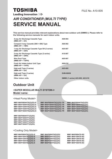
FILE No. A10-005AIR CONDITIONER (MULTI TYPE)<strong>SERVICE</strong> <strong>MANUAL</strong>This service manual provides relevant explanations about new outdoor unit (SMMS-i). Please refer tothe following service manuals for each indoor units.4-way Air Discharge Cassette Type(MMU-AP2H)Compact 4-way Cassette (600 × 600) Type(MMU-AP1MH)1-way Air Discharge Cassette Type SH (2 series)(MMU-AP2SH)2-way Air Discharge Cassette Type (2 series)(MMU-AP2WH)Slim Duct Type(MMD-AP1SPH)Fresh Air Intake Indoor Unit Type(MMD-AP1HFE)High-wall Type (2 series)(MMK-AP2H)High-wall Type (3 series)(MMK-AP3H)A08-004A06-002A05-007A10-007A05-007A06-016A05-005SVM-09059Other indoor units SMMS (1 series) A03-009, A03-010Outdoor UnitModel name:MMY-MAP0804HT8(Z)(ZG)-EMMY-MAP1004HT8(Z)(ZG)-EMMY-MAP1204HT8(Z)(ZG)-EMMY-MAP1404HT8(Z)(ZG)-EMMY-MAP1604HT8(Z)(ZG)-EMMY-MAP0804HT8(Z)(ZG)-TRMMY-MAP1004HT8(Z)(ZG)-TRMMY-MAP1204HT8(Z)(ZG)-TRMMY-MAP1404HT8(Z)(ZG)-TRMMY-MAP1604HT8(Z)(ZG)-TRMMY-MAP0804HT8(Z)(ZG)MMY-MAP1004HT8(Z)(ZG)MMY-MAP1204HT8(Z)(ZG)MMY-MAP1404HT8(Z)(ZG)MMY-MAP1604HT8(Z)(ZG)MMY-MAP0804HT7(Z)(ZG)MMY-MAP1004HT7(Z)(ZG)MMY-MAP1204HT7(Z)(ZG)MMY-MAP1404HT7(Z)(ZG)MMY-MAP1604HT7(Z)(ZG)MMY-MAP0804T8(Z)(ZG)-EMMY-MAP1004T8(Z)(ZG)-EMMY-MAP1204T8(Z)(ZG)-EMMY-MAP1404T8(Z)(ZG)-EMMY-MAP1604T8(Z)(ZG)-EMMY-MAP0804T8(Z)(ZG)MMY-MAP1004T8(Z)(ZG)MMY-MAP1204T8(Z)(ZG)MMY-MAP1404T8(Z)(ZG)MMY-MAP1604T8(Z)(ZG)MMY-MAP0804T8-SGMMY-MAP1004T8-SGMMY-MAP1204T8-SGMMY-MAP1404T8-SGMMY-MAP1604T8-SG
ContentsOriginal instruction . . . . . . . . . . . . . . . . . . . . . . . . . . . . . . . . . . . . . . . . . . . . . . . . . . . . 5New Refrigerant (R410A). . . . . . . . . . . . . . . . . . . . . . . . . . . . . . . . . . . . . . . . . . . . . . . 211 Wiring Diagrams . . . . . . . . . . . . . . . . . . . . . . . . . . . . . . . . . . . . . . . . . . . . . . . . . . . . . 231-1. Outdoor Unit . . . . . . . . . . . . . . . . . . . . . . . . . . . . . . . . . . . . . . . . . . . . . . . . . . . . . . . . . . . . . . . . 231-2. Indoor Unit . . . . . . . . . . . . . . . . . . . . . . . . . . . . . . . . . . . . . . . . . . . . . . . . . . . . . . . . . . . . . . . . . . 251-2-1. 4-way Air Discharge Cassette Type . . . . . . . . . . . . . . . . . . . . . . . . . . . . . . . . . . . . . . . . 251-2-2. Compact 4-way Cassette Type . . . . . . . . . . . . . . . . . . . . . . . . . . . . . . . . . . . . . . . . . . . 261-2-3. 1-way Air Discharge Cassette Type (Compact type) . . . . . . . . . . . . . . . . . . . . . . . . . . . 271-2-4. 1-way Air Discharge Cassette Type SH 2 series . . . . . . . . . . . . . . . . . . . . . . . . . . . . . . 281-2-5. 2-way Air Discharge Cassette Type 1 series . . . . . . . . . . . . . . . . . . . . . . . . . . . . . . . . . 291-2-6. 2-way Air Discharge Cassette Type 2 series . . . . . . . . . . . . . . . . . . . . . . . . . . . . . . . . . 301-2-7. Concealed Duct Standard Type . . . . . . . . . . . . . . . . . . . . . . . . . . . . . . . . . . . . . . . . . . . 311-2-8. Concealed Duct High Static Pressure Type . . . . . . . . . . . . . . . . . . . . . . . . . . . . . . . . . . 321-2-9. Slim Duct Type . . . . . . . . . . . . . . . . . . . . . . . . . . . . . . . . . . . . . . . . . . . . . . . . . . . . . . . . 341-2-10. Under Ceiling Type. . . . . . . . . . . . . . . . . . . . . . . . . . . . . . . . . . . . . . . . . . . . . . . . . . . . . 351-2-11. High Wall Type 2 series . . . . . . . . . . . . . . . . . . . . . . . . . . . . . . . . . . . . . . . . . . . . . . . . . 361-2-12. High Wall Type 3 series . . . . . . . . . . . . . . . . . . . . . . . . . . . . . . . . . . . . . . . . . . . . . . . . . 371-2-13. Floor Standing Cabinet Type . . . . . . . . . . . . . . . . . . . . . . . . . . . . . . . . . . . . . . . . . . . . . 381-2-14. Floor Standing Concealed Type. . . . . . . . . . . . . . . . . . . . . . . . . . . . . . . . . . . . . . . . . . . 391-2-15. Floor Standing Type . . . . . . . . . . . . . . . . . . . . . . . . . . . . . . . . . . . . . . . . . . . . . . . . . . . . 401-2-16. Fresh Air Intake Indoor Unit for S-MMS . . . . . . . . . . . . . . . . . . . . . . . . . . . . . . . . . . . . . 412 Parts Rating . . . . . . . . . . . . . . . . . . . . . . . . . . . . . . . . . . . . . . . . . . . . . . . . . . . . . . . . . 432-1. Outdoor Unit (50Hz model: MMY-MAP4HT8-E, MAP4HT8-TR, MAP4HT8, MAP4T8-SG) . . . . . . . . . . . . . . . . . . . . . . . . . . . . . . . . . . . . . . . . . . . . . . . . . . . . . . . . . . . . . . . . . . . . . . . 432-2. Outdoor Unit (60Hz model: MMY-MAP4HT7) . . . . . . . . . . . . . . . . . . . . . . . . . . . . . . . . . . . . 442-3. Outdoor Inverter (50Hz model: MMY-MAP4HT8-E, MAP4HT8-TR, MAP4HT8,MAP4T8-SG) . . . . . . . . . . . . . . . . . . . . . . . . . . . . . . . . . . . . . . . . . . . . . . . . . . . . . . . . . . . . . 452-4. Outdoor Inverter (60Hz model: MMY-MAP4HT7) . . . . . . . . . . . . . . . . . . . . . . . . . . . . . . . . . 462-5. Indoor Unit . . . . . . . . . . . . . . . . . . . . . . . . . . . . . . . . . . . . . . . . . . . . . . . . . . . . . . . . . . . . . . . . . . 472-6. Parts Layout in Outdoor Unit . . . . . . . . . . . . . . . . . . . . . . . . . . . . . . . . . . . . . . . . . . . . . . . . . . . . 532-7. Parts Layout in Inverter Assembly. . . . . . . . . . . . . . . . . . . . . . . . . . . . . . . . . . . . . . . . . . . . . . . . 552-8. Outdoor (Inverter) Print Circuit Board . . . . . . . . . . . . . . . . . . . . . . . . . . . . . . . . . . . . . . . . . . . . . 572-8-1. Interface P.C. board (MCC-1606) . . . . . . . . . . . . . . . . . . . . . . . . . . . . . . . . . . . . . . . . . 572-8-2. Inverter P.C. board for compressor (MCC-1596) A3-IPDU . . . . . . . . . . . . . . . . . . . . . . 582-8-3. Inverter P.C. board for fan (MCC-1610) . . . . . . . . . . . . . . . . . . . . . . . . . . . . . . . . . . . . . 593 Refrigerant Piping Systematic Drawing . . . . . . . . . . . . . . . . . . . . . . . . . . . . . . . . . . 604 Combined Refrigerant Piping System Schematic Diagrams. . . . . . . . . . . . . . . . . . 641
4-1. Normal Operation (COOL Mode / DEFROST Mode) - High Outside Air Temperature (Roughly 20°C or Above) . . . . . . . . . . . . . . . . . . . . . . . . . . . . . . . . . . . . . . . . . . . . . . . . . . . . . . . . . . . . . . . . 644-2. Normal Operation (COOL Mode) - Low Outside Air Temperature (Roughly Below 20 °C) . . . . . 654-3. Normal Operation (HEAT Mode) . . . . . . . . . . . . . . . . . . . . . . . . . . . . . . . . . . . . . . . . . . . . . . . . . 664-4. Emergency Operation (Cooling Operation under Header Outdoor Unit Backup Scenario). . . . . 674-5. Emergency Operation (Heating Operation under Header Outdoor Unit Backup Scenario). . . . . 684-6. Refrigerant Recovery from Failed Outdoor Unit (Pump-Down Operation under Follower OutdoorUnit Backup Scenario). . . . . . . . . . . . . . . . . . . . . . . . . . . . . . . . . . . . . . . . . . . . . . . . . . . . . . . . . 695 Control Outline. . . . . . . . . . . . . . . . . . . . . . . . . . . . . . . . . . . . . . . . . . . . . . . . . . . . . . . 706 Applied Control and Functions (including Circuit Configuration) . . . . . . . . . . . . . 856-1. Indoor Controller Block Diagram . . . . . . . . . . . . . . . . . . . . . . . . . . . . . . . . . . . . . . . . . . . . . . . . . 856-1-1. When Main (Sub) Remote Controller Connected. . . . . . . . . . . . . . . . . . . . . . . . . . . . . . 856-1-2. When Wireless Remote Controller Kit Connected . . . . . . . . . . . . . . . . . . . . . . . . . . . . . 886-1-3. When Both Main (Sub) Remote Controller and Wireless Remote Controller Kit Connected .916-2. Indoor Printed Circuit Board . . . . . . . . . . . . . . . . . . . . . . . . . . . . . . . . . . . . . . . . . . . . . . . . . . . . 946-3. Optional Connector Specifications of Indoor P.C. Board. . . . . . . . . . . . . . . . . . . . . . . . . . . . . . . 976-4. Test Operation of Indoor Unit . . . . . . . . . . . . . . . . . . . . . . . . . . . . . . . . . . . . . . . . . . . . . . . . . . . 986-5. Method to Set Indoor Unit Function DN Code . . . . . . . . . . . . . . . . . . . . . . . . . . . . . . . . . . . . . . . 996-6. Applied Control of Indoor Unit . . . . . . . . . . . . . . . . . . . . . . . . . . . . . . . . . . . . . . . . . . . . . . . . . 1036-7. Applied control for Outdoor Unit . . . . . . . . . . . . . . . . . . . . . . . . . . . . . . . . . . . . . . . . . . . . . . . . 1066-7-1. Outdoor Fan High Static Pressure Shift . . . . . . . . . . . . . . . . . . . . . . . . . . . . . . . . . . . . 1066-7-2. Priority Operation Mode Setting . . . . . . . . . . . . . . . . . . . . . . . . . . . . . . . . . . . . . . . . . . 1076-8. Applied Control of Outdoor Unit. . . . . . . . . . . . . . . . . . . . . . . . . . . . . . . . . . . . . . . . . . . . . . . . . 1096-8-1. Power peak-cut Control (Standard) . . . . . . . . . . . . . . . . . . . . . . . . . . . . . . . . . . . . . . . 1106-8-2. Power peak-cut Control (Extended) . . . . . . . . . . . . . . . . . . . . . . . . . . . . . . . . . . . . . . . 1116-8-3. Snowfall Fan Control . . . . . . . . . . . . . . . . . . . . . . . . . . . . . . . . . . . . . . . . . . . . . . . . . . 1126-8-4. External master ON/OFF Control . . . . . . . . . . . . . . . . . . . . . . . . . . . . . . . . . . . . . . . . . 1126-8-5. Night operation (sound reduction) Control . . . . . . . . . . . . . . . . . . . . . . . . . . . . . . . . . . 1136-8-6. Operation Mode Selection Control . . . . . . . . . . . . . . . . . . . . . . . . . . . . . . . . . . . . . . . . 1146-8-7. Error/Operation Output. . . . . . . . . . . . . . . . . . . . . . . . . . . . . . . . . . . . . . . . . . . . . . . . . 1156-8-8. Compressor Operation Output . . . . . . . . . . . . . . . . . . . . . . . . . . . . . . . . . . . . . . . . . . . 1166-8-9. Operating Rate Output . . . . . . . . . . . . . . . . . . . . . . . . . . . . . . . . . . . . . . . . . . . . . . . . . 1177 TEST OPERATION . . . . . . . . . . . . . . . . . . . . . . . . . . . . . . . . . . . . . . . . . . . . . . . . . . . 1187-1. Procedure and Summary of Test Operation . . . . . . . . . . . . . . . . . . . . . . . . . . . . . . . . . . . . . . . 1187-2. Check Items before Test Operation (before powering-on) . . . . . . . . . . . . . . . . . . . . . . . . . . . . 1197-3. Check at Main Power-on . . . . . . . . . . . . . . . . . . . . . . . . . . . . . . . . . . . . . . . . . . . . . . . . . . . . . . 1237-4. Address Setup . . . . . . . . . . . . . . . . . . . . . . . . . . . . . . . . . . . . . . . . . . . . . . . . . . . . . . . . . . . . . . 1247-4-1. Precautions . . . . . . . . . . . . . . . . . . . . . . . . . . . . . . . . . . . . . . . . . . . . . . . . . . . . . . . . . 1247-4-2. Address Setup and Check Procedure . . . . . . . . . . . . . . . . . . . . . . . . . . . . . . . . . . . . . 1247-4-3. Address Setup Procedure . . . . . . . . . . . . . . . . . . . . . . . . . . . . . . . . . . . . . . . . . . . . . . 1257-4-4. Check after Address Setup when Central Control System Is Connected . . . . . . . . . . 1382
7-5. Troubleshooting in Test Operation . . . . . . . . . . . . . . . . . . . . . . . . . . . . . . . . . . . . . . . . . . . . . . 1397-5-1. A Check Code Is Displayed on the Remote Controller . . . . . . . . . . . . . . . . . . . . . . . . 1397-5-2. Operation from the indoor remote controller is not accepted, and a check code is displayedon the 7-segment display of the interface PC board of the header unit. . . . . . . . . . . . 1407-5-3. There is no display of a check code on the 7-segment display on the interface PC board ofthe header unit, although there is indoor unit that is not accepting operation from the indoorremote controller. . . . . . . . . . . . . . . . . . . . . . . . . . . . . . . . . . . . . . . . . . . . . . . . . . . . . . 1407-5-4. In checking the number of connected outdoor units and connected indoor units after addresssetup, a lower number of connected units is displayed. (There are outdoor/indoorunits that do not operate in a test operation.). . . . . . . . . . . . . . . . . . . . . . . . . . . . . . . . 1417-6. Test Operation Check . . . . . . . . . . . . . . . . . . . . . . . . . . . . . . . . . . . . . . . . . . . . . . . . . . . . . . . . 1437-6-1. Fan Check . . . . . . . . . . . . . . . . . . . . . . . . . . . . . . . . . . . . . . . . . . . . . . . . . . . . . . . . . . 1437-6-2. Cooling/Heating Test Operation Check . . . . . . . . . . . . . . . . . . . . . . . . . . . . . . . . . . . . 1447-7. Service Support Function . . . . . . . . . . . . . . . . . . . . . . . . . . . . . . . . . . . . . . . . . . . . . . . . . . . . . 1487-7-1. Check Function for Connecting of Refrigerant and Control Lines . . . . . . . . . . . . . . . . 1487-7-2. Function to Start/Stop (ON/OFF) Indoor Unit from Outdoor Unit . . . . . . . . . . . . . . . . . 1507-7-3. Error Clearing Function . . . . . . . . . . . . . . . . . . . . . . . . . . . . . . . . . . . . . . . . . . . . . . . . 1557-7-4. Remote Controller Distinction Function . . . . . . . . . . . . . . . . . . . . . . . . . . . . . . . . . . . . 1577-7-5. Pulse Motor Valve (PMV) Forced Open/Close Function in Indoor Unit . . . . . . . . . . . . 1587-7-6. Pulse Motor Valve (PMV) Forced Open Fully/Close fully Function in Outdoor Unit. . . 1587-7-7. Solenoid Valve Forced Open/Close Function in Outdoor Unit . . . . . . . . . . . . . . . . . . . 1597-7-8. Fan Operation Check in Outdoor Unit . . . . . . . . . . . . . . . . . . . . . . . . . . . . . . . . . . . . . 1607-7-9. Abnormal Outdoor Unit Discrimination Method By Fan Operating Function . . . . . . . . 1617-7-10. Manual Adjustment Function of Outside Temperature (TO) Sensor . . . . . . . . . . . . . . 1627-7-11. Monitor Function of Remote Controller Switch. . . . . . . . . . . . . . . . . . . . . . . . . . . . . . . 1648 TROUBLESHOOTING . . . . . . . . . . . . . . . . . . . . . . . . . . . . . . . . . . . . . . . . . . . . . . . . 1668-1. Overview . . . . . . . . . . . . . . . . . . . . . . . . . . . . . . . . . . . . . . . . . . . . . . . . . . . . . . . . . . . . . . . . . . 1668-2. Troubleshooting Method . . . . . . . . . . . . . . . . . . . . . . . . . . . . . . . . . . . . . . . . . . . . . . . . . . . . . . 1678-3. Troubleshooting Based on Information Displayed on Remote Controller . . . . . . . . . . . . . . . . . 1738-4. Check Codes Displayed on Remote Controller and SMMS-i Outdoor Unit (7-Segment Display on I/F Board) and Locations to Be Checked. . . . . . . . . . . . . . . . . . . . . . . . . . . . . . . . . . . . . . . . . . . 1788-5. Diagnosis procedure for each check code . . . . . . . . . . . . . . . . . . . . . . . . . . . . . . . . . . . . . . . . 1948-6. 7-Segment Display Function . . . . . . . . . . . . . . . . . . . . . . . . . . . . . . . . . . . . . . . . . . . . . . . . . . . 2258-7. Oil Level Judgment Display . . . . . . . . . . . . . . . . . . . . . . . . . . . . . . . . . . . . . . . . . . . . . . . . . . . . 2318-8. Leakage/Clogging of Refrigerating Cycle Circuit. . . . . . . . . . . . . . . . . . . . . . . . . . . . . . . . . . . . 2328-9. Sensor Characteristics . . . . . . . . . . . . . . . . . . . . . . . . . . . . . . . . . . . . . . . . . . . . . . . . . . . . . . . 2368-10. Pressure Sensor Output Check. . . . . . . . . . . . . . . . . . . . . . . . . . . . . . . . . . . . . . . . . . . . . . . . . 2399 BACKUP OPERATION (EMERGENCY OPERATION) . . . . . . . . . . . . . . . . . . . . . . . 2419-1. Note for Backup Operation . . . . . . . . . . . . . . . . . . . . . . . . . . . . . . . . . . . . . . . . . . . . . . . . . . . . 2419-2. Compressor Backup Operation Setting . . . . . . . . . . . . . . . . . . . . . . . . . . . . . . . . . . . . . . . . . . . 2429-3. Outdoor Unit Backup Operation Setting . . . . . . . . . . . . . . . . . . . . . . . . . . . . . . . . . . . . . . . . . . 2439-3-1. Follower outdoor unit backup operation setting (failure of follower outdoor unit) . . . . . 2439-3-2. Header outdoor unit backup operation setting (failure of header outdoor unit) . . . . . . 2453
9-4. Cooling-Season Outdoor Unit Backup Operation Setting . . . . . . . . . . . . . . . . . . . . . . . . . . . . . 24710 OUTDOOR UNIT REFRIGERANT RECOVERY METHOD . . . . . . . . . . . . . . . . . . . . 24810-1. Refrigerant Recovery from Failed Outdoor Unit (Pump-Down) . . . . . . . . . . . . . . . . . . . . . . . . . 24810-1-1. Note for refrigerant recovery operation . . . . . . . . . . . . . . . . . . . . . . . . . . . . . . . . . . . . 24810-1-2. Refrigerant recovery procedure A (Case of no outdoor unit backup operation setting) 24810-1-3. Refrigerant recovery procedure B (Case of outdoor unit backup operation setting) . . 25110-2. How to Operate System While Failed Outdoor Unit Being Repaired. . . . . . . . . . . . . . . . . . . . . 25310-3. Work procedure after Repair . . . . . . . . . . . . . . . . . . . . . . . . . . . . . . . . . . . . . . . . . . . . . . . . . . . 25411 REPLACING COMPRESSORS . . . . . . . . . . . . . . . . . . . . . . . . . . . . . . . . . . . . . . . . . 25511-1. Compressor Replacement Procedure (Outline). . . . . . . . . . . . . . . . . . . . . . . . . . . . . . . . . . . . . 25511-2. Replacement of Compressors . . . . . . . . . . . . . . . . . . . . . . . . . . . . . . . . . . . . . . . . . . . . . . . . . . 25611-3. Check Procedure to Search Cause of Compressor Oil Shortage . . . . . . . . . . . . . . . . . . . . . . . 26012 OUTDOOR UNIT PARTS REPLACEMENT METHODS . . . . . . . . . . . . . . . . . . . . . . 26313 P.C. BOARD EXCHANGE PROCEDURES . . . . . . . . . . . . . . . . . . . . . . . . . . . . . . . . 27613-1. Replacement of Indoor P.C. Boards . . . . . . . . . . . . . . . . . . . . . . . . . . . . . . . . . . . . . . . . . . . . . 27613-2. Replacement of Outdoor P.C. Boards . . . . . . . . . . . . . . . . . . . . . . . . . . . . . . . . . . . . . . . . . . . . 28313-2-1. List of service P.C. boards . . . . . . . . . . . . . . . . . . . . . . . . . . . . . . . . . . . . . . . . . . . . . . 28313-2-2. Configuration of inverter assembly. . . . . . . . . . . . . . . . . . . . . . . . . . . . . . . . . . . . . . . . 28313-2-3. Interface board (MCC-1606) replacement method. . . . . . . . . . . . . . . . . . . . . . . . . . . . 28413-2-4. Comp-IPDU P.C. Board (MCC-1596) Replacement Procedure. . . . . . . . . . . . . . . . . . 28513-2-5. Fan IPDU P.C. Board (MCC-1610) Replacement Procedure . . . . . . . . . . . . . . . . . . . 28713-2-6. Noise Filter P.C. Board (MCC-1608 A, B) Replacement Procedure . . . . . . . . . . . . . . 28814 EXPLODED DIAGRAM/PARTS PRICE LIST. . . . . . . . . . . . . . . . . . . . . . . . . . . . . . . 2914
Original instructionPlease read carefully through these instructions that contain important information which complies with the“Machinery” Directive (Directive 2006/42/EC), and ensure that you understand them.Some of the details provided in these instructions differ from the service manual, and the instructions provided heretake precedence.Generic Denomination: Air ConditionerDefinition of Qualified Installer or Qualified Service PersonThe air conditioner must be installed, maintained, repaired and removed by a qualified installer or qualified serviceperson. When any of these jobs is to be done, ask a qualified installer or qualified service person to do them for you.A qualified installer or qualified service person is an agent who has the qualifications and knowledge described inthe table below.AgentQualified installerQualified servicepersonQualifications and knowledge which the agent must have• The qualified installer is a person who installs, maintains, relocates and removes the air conditionersmade by <strong>Toshiba</strong> Carrier Corporation. He or she has been trained to install, maintain, relocate andremove the air conditioners made by <strong>Toshiba</strong> Carrier Corporation or, alternatively, he or she has beeninstructed in such operations by an individual or individuals who have been trained and is thusthoroughly acquainted with the knowledge related to these operations.• The qualified installer who is allowed to do the electrical work involved in installation, relocation andremoval has the qualifications pertaining to this electrical work as stipulated by the local laws andregulations, and he or she is a person who has been trained in matters relating to electrical work onthe air conditioners made by <strong>Toshiba</strong> Carrier Corporation or, alternatively, he or she has beeninstructed in such matters by an individual or individuals who have been trained and is thus thoroughlyacquainted with the knowledge related to this work.• The qualified installer who is allowed to do the refrigerant handling and piping work involved ininstallation, relocation and removal has the qualifications pertaining to this refrigerant handling andpiping work as stipulated by the local laws and regulations, and he or she is a person who has beentrained in matters relating to refrigerant handling and piping work on the air conditioners made by<strong>Toshiba</strong> Carrier Corporation or, alternatively, he or she has been instructed in such matters by anindividual or individuals who have been trained and is thus thoroughly acquainted with the knowledgerelated to this work.• The qualified installer who is allowed to work at heights has been trained in matters relating to workingat heights with the air conditioners made by <strong>Toshiba</strong> Carrier Corporation or, alternatively, he or shehas been instructed in such matters by an individual or individuals who have been trained and is thusthoroughly acquainted with the knowledge related to this work.• The qualified service person is a person who installs, repairs, maintains, relocates and removes theair conditioners made by <strong>Toshiba</strong> Carrier Corporation. He or she has been trained to install, repair,maintain, relocate and remove the air conditioners made by <strong>Toshiba</strong> Carrier Corporation or,alternatively, he or she has been instructed in such operations by an individual or individuals who havebeen trained and is thus thoroughly acquainted with the knowledge related to these operations.• The qualified service person who is allowed to do the electrical work involved in installation, repair,relocation and removal has the qualifications pertaining to this electrical work as stipulated by the locallaws and regulations, and he or she is a person who has been trained in matters relating to electricalwork on the air conditioners made by <strong>Toshiba</strong> Carrier Corporation or, alternatively, he or she has beeninstructed in such matters by an individual or individuals who have been trained and is thus thoroughlyacquainted with the knowledge related to this work.• The qualified service person who is allowed to do the refrigerant handling and piping work involved ininstallation, repair, relocation and removal has the qualifications pertaining to this refrigerant handlingand piping work as stipulated by the local laws and regulations, and he or she is a person who hasbeen trained in matters relating to refrigerant handling and piping work on the air conditioners madeby <strong>Toshiba</strong> Carrier Corporation or, alternatively, he or she has been instructed in such matters by anindividual or individuals who have been trained and is thus thoroughly acquainted with the knowledgerelated to this work.• The qualified service person who is allowed to work at heights has been trained in matters relating toworking at heights with the air conditioners made by <strong>Toshiba</strong> Carrier Corporation or, alternatively, heor she has been instructed in such matters by an individual or individuals who have been trained andis thus thoroughly acquainted with the knowledge related to this work.5
Definition of Protective GearWhen the air conditioner is to be transported, installed, maintained, repaired or removed, wear protective glovesand ‘safety’ work clothing.In addition to such normal protective gear, wear the protective gear described below when undertaking the specialwork detailed in the table below.Failure to wear the proper protective gear is dangerous because you will be more susceptible to injury, burns,electric shocks and other injuries.All types of workWork undertakenElectrical-related workWork done at heights(50 cm or more)Transportation of heavy objectsRepair of outdoor unitProtective gloves‘Safety’ working clothingProtective gear wornGloves to provide protection for electricians and from heatInsulating shoesClothing to provide protection from electric shockHelmets for use in industryShoes with additional protective toe capGloves to provide protection for electricians and from heatThe important contents concerned to the safety are described on the product itself and on this Service Manual.Please read this Service Manual after understanding the described items thoroughly in the following contents(Indications/Illustrated marks), and keep them.[Explanation of indications]IndicationDANGERWARNINGCAUTIONExplanationIndicates contents assumed that an imminent danger causing a death or serious injury ofthe repair engineers and the third parties when an incorrect work has been executed.Indicates possibilities assumed that a danger causing a death or serious injury of therepair engineers, the third parties, and the users due to troubles of the product after workwhen an incorrect work has been executed.Indicates contents assumed that an injury or property damage (*) may be caused on therepair engineers, the third parties, and the users due to troubles of the product after workwhen an incorrect work has been executed.* Property damage: Enlarged damage concerned to property, furniture, and domestic animal/pet[Explanation of illustrated marks]MarkExplanationIndicates prohibited items (Forbidden items to do)The sentences near an illustrated mark describe the concrete prohibited contents.Indicates mandatory items (Compulsory items to do)The sentences near an illustrated mark describe the concrete mandatory contents.Indicates cautions (Including danger/warning)The sentences or illustration near or in an illustrated mark describe the concrete cautious contents.6
Warning Indications on the Air Conditioner Unit[Confirmation of warning label on the main unit]Confirm that labels are indicated on the specified positionsIf removing the label during parts replace, stick it as the original.Warning indicationDescriptionWARNINGELECTRICAL SHOCK HAZARDDisconnect all remoteelectric power suppliesbefore servicing.WARNINGELECTRICAL SHOCK HAZARDDisconnect all remote electric power supplies before servicing.WARNINGMoving parts.Do not operate unit with grilleremoved.Stop the unit before the servicing.WARNINGMoving parts.Do not operate unit with grille removed.Stop the unit before the servicing.CAUTIONHigh temperature parts.You might get burnedwhen removing this panel.CAUTIONHigh temperature parts.You might get burned when removing this panel.CAUTIONDo not touch the aluminumfins of the unit.Doing so may result in injury.CAUTIONDo not touch the aluminium fins of the unit.Doing so may result in injury.CAUTIONBURST HAZARDOpen the service valves beforethe operation, otherwise theremight be the burst.CAUTIONBURST HAZARDOpen the service valves before the operation, otherwise there might be theburst.CAUTIONDo not climb onto thefan guard.Doing so may result in injury.CAUTIONDo not climb onto the fan guard.Doing so may result in injury.7
Precautions for SafetyThe manufacturer shall not assume any liability for the damage caused by not observing the description of thismanual.DANGERTurn offbreaker.Before carrying out the installation, maintenance, repair or removal work, be sure to set the circuit breaker forboth the indoor and outdoor units to the OFF position. Otherwise, electric shocks may result.Before opening the intake grille of the indoor unit or service panel of the outdoor unit, set the circuit breaker tothe OFF position.Failure to set the circuit breaker to the OFF position may result in electric shocks through contact with the interiorparts.Only a qualified installer (*1) or qualified service person (*1) is allowed to remove the intake grille of the indoorunit or service panel of the outdoor unit and do the work required.Before starting to repair the outdoor unit fan or fan guard, be absolutely sure to set the circuitbreaker to the OFF position, and place a “Work in progress” sign on the circuit breaker.When cleaning the filter or other parts of the indoor unit, set the circuit breaker to OFF withoutfail, and place a “Work in progress” sign near the circuit breaker before proceeding with the work.When you have noticed that some kind of trouble (such as when an error display has appeared, there is a smellof burning, abnormal sounds are heard, the air conditioner fails to cool or heat or water is leaking) has occurredin the air conditioner, do not touch the air conditioner yourself but set the circuit breaker to the OFF position,and contact a qualified service person. Take steps to ensure that the power will not be turned on (by marking“out of service” near the circuit breaker, for instance) until qualified service person arrives. Continuing to use theair conditioner in the trouble status may cause mechanical problems to escalate or result in electric shocks orother failure.Electric shockhazardProhibitionStay onprotectionWhen you access inside of the service panel to repair electric parts, wait for about five minutes after turning offthe breaker. Do not start repairing immediately.Otherwise you may get electric shock by touching terminals ofhigh-voltage capacitors. Natural discharge of the capacitor takes about five minutes.Place a “Work in progress” sign near the circuit breaker while the installation, maintenance, repair or removalwork is being carried out.There is a danger of electric shocks if the circuit breaker is set to ON by mistake.Before operating the air conditioner after having completed the work, check that the electrical parts box coverof the indoor unit and service panel of the outdoor unit are closed, and set the circuit breaker to the ON position.You may receive an electric shock if the power is turned on without first conducting these checks.If, in the course of carrying out repairs, it becomes absolutely necessary to check out the electrical parts withthe electrical parts box cover of one or more of the indoor units and the service panel of the outdoor unitremoved in order to find out exactly where the trouble lies, wear insulated heat-resistant gloves, insulated bootsand insulated work overalls, and take care to avoid touching any live parts.You may receive an electric shock if you fail to heed this warning. Only qualified service person (*1) is allowedto do this kind of work.8
WARNINGGeneralCheck earthwires.Before starting to repair the air conditioner, read carefully through the Service Manual, and repair the airconditioner by following its instructions.Only qualified service person (*1) is allowed to repair the air conditioner.Repair of the air conditioner by unqualified person may give rise to a fire, electric shocks, injury, water leaksand/or other problems.Do not use any refrigerant different from the one specified for complement or replacement.Otherwise, abnormally high pressure may be generated in the refrigeration cycle, which may result in a failureor explosion of the product or an injury to your body.Only a qualified installer (*1) or qualified service person (*1) is allowed to carry out the electrical work of the airconditioner.Under no circumstances must this work be done by an unqualified individual since failure to carry out the workproperly may result in electric shocks and/or electrical leaks.When transporting the air conditioner, wear shoes with protective toe caps, protective gloves and otherprotective clothing.When connecting the electrical wires, repairing the electrical parts or undertaking other electrical jobs, weargloves to provide protection for electricians and from heat, insulating shoes and clothing to provide protectionfrom electric shocks.Failure to wear this protective gear may result in electric shocks.Electrical wiring work shall be conducted according to law and regulation in the community and installationmanual. Failure to do so may result in electrocution or short circuit.Only a qualified installer (*1) or qualified service person (*1) is allowed to undertake work atheights using a stand of 50 cm or more or to remove the intake grille of the indoor unit toundertake work.When working at heights, use a ladder which complies with the ISO 14122 standard, and follow the procedurein the ladder’s instructions.Also wear a helmet for use in industry as protective gear to undertake the work.When working at heights, put a sign in place so that no-one will approach the work location, before proceedingwith the work.Parts and other objects may fall from above, possibly injuring a person below.When executing address setting, test run, or troubleshooting through the checking window on the electric partsbox, put on insulated gloves to provide protection from electric shock. Otherwise you may receive an electricshock.Do not touch the aluminum fin of the outdoor unit.You may injure yourself if you do so. If the fin must be touched for some reason, first put on protective glovesand safety work clothing, and then proceed.Do not climb onto or place objects on top of the outdoor unit.You may fall or the objects may fall off of the outdoor unit and result in injury.When transporting the air conditioner, wear shoes with additional protective toe caps.When transporting the air conditioner, do not take hold of the bands around the packing carton.You may injure yourself if the bands should break.Be sure that a heavy unit (10kg or heavier) such as a compressor is carried by two persons.This air conditioner has passed the pressure test as specified in IEC 60335-2-40 Annex EE.Before troubleshooting or repair work, check the earth wire is connected to the earth terminals of the main unit,otherwise an electric shock is caused when a leak occurs.If the earth wire is not correctly connected, contactan electric engineer for rework.After completing the repair or relocation work, check that the ground wires are connected properly.Be sure to connect earth wire. (Grounding work) Incomplete grounding causes an electric shock.Do not connect ground wires to gas pipes, water pipes, and lightning rods or ground wires for telephone wires.Prohibition ofmodification.Do not modify the products.Do not also disassemble or modify the parts.It may cause a fire, electric shock or injury.9
Use specifiedparts.When any of the electrical parts are to be replaced, ensure that the replacement parts satisfy the specificationsgiven in the Service Manual (or use the parts contained on the parts list in the Service Manual).Use of any parts which do not satisfy the required specifications may give rise to electric shocks, smoking and/or a fire.Do not bring achild close totheequipment.If, in the course of carrying out repairs, it becomes absolutely necessary to check out the electrical parts withthe electrical parts box cover of one or more of the indoor units and the service panel of the outdoor unitremoved in order to find out exactly where the trouble lies, put a sign in place so that no-one will approach thework location before proceeding with the work. Third-party individuals may enter the work site and receiveelectric shocks if this warning is not heeded.InsulatingmeasuresNo fireRefrigerantAssembly/WiringConnect the cut-off lead wires with crimp contact, etc., put the closed end side upward and then apply a watercutmethod, otherwise a leak or production of fire is caused at the users’ side.When performing repairs using a gas burner, replace the refrigerant with nitrogen gas because the oil that coatsthe pipes may otherwise burn.When repairing the refrigerating cycle, take the following measures.1) Be attentive to fire around the cycle. When using a gas stove, etc., be sure to put out fire before work;otherwise the oil mixed with refrigerant gas may catch fire.2) Do not use a welder in the closed room. When using it without ventilation, carbon monoxide poisoning maybe caused.3) Do not bring inflammables close to the refrigerant cycle, otherwise fire of the welder may catch theinflammables.The refrigerant used by this air conditioner is the R410A.Check the used refrigerant name and use tools and materials of the parts which match with it.For the products which use R410A refrigerant, the refrigerant name is indicated at a position on the outdoor unitwhere is easy to see. To prevent miss-charging, the route of the service port is changed from one of the formerR22.For an air conditioner which uses R410A, never use other refrigerant than R410A. For an air conditioner whichuses other refrigerant (R22, etc.), never use R410A.If different types of refrigerant are mixed, abnormal high pressure generates in the refrigerating cycle and aninjury due to breakage may be caused.When the air conditioner has been installed or relocated, follow the instructions in the Installation Manual andpurge the air completely so that no gases other than the refrigerant will be mixed in the refrigerating cycle.Failure to purge the air completely may cause the air conditioner to malfunction.Do not charge refrigerant additionally. If charging refrigerant additionally when refrigerant gas leaks, therefrigerant composition in the refrigerating cycle changes resulted in change of air conditioner characteristics orrefrigerant over the specified standard amount is charged and an abnormal high pressure is applied to the insideof the refrigerating cycle resulted in cause of breakage or injury. Therefore if the refrigerant gas leaks, recoverthe refrigerant in the air conditioner, execute vacuuming, and then newly recharge the specified amount of liquidrefrigerant.In this time, never charge the refrigerant over the specified amount.When recharging the refrigerant in the refrigerating cycle, do not mix the refrigerant or air other than R410A intothe specified refrigerant. If air or others is mixed with the refrigerant, abnormal high pressure generates in therefrigerating cycle resulted in cause of injury due to breakage.After installation work, check the refrigerant gas does not leak. If the refrigerant gas leaks in the room,poisonous gas generates when gas touches to fire such as fan heater, stove or cocking stove though therefrigerant gas itself is innocuous.Never recover the refrigerant into the outdoor unit. When the equipment is moved or repaired, be sure to recoverthe refrigerant with recovering device.The refrigerant cannot be recovered in the outdoor unit; otherwise a serious accident such as breakage or injuryis caused.After repair work, surely assemble the disassembled parts, and connect and lead the removed wires as before.Perform the work so that the cabinet or panel does not catch the inner wires.If incorrect assembly or incorrect wire connection was done, a disaster such as a leak or fire is caused at user’sside.InsulatorcheckAfter the work has finished, be sure to use an insulation tester set (500V Megger) to check the resistance is1M or more between the charge section and the non-charge metal section (Earth position).If the resistance value is low, a disaster such as a leak or electric shock is caused at user’s side.10
VentilationCompulsionCheck afterrepairDo notoperate theunit with thevalve closed.Check afterreinstallationCooling checkWhen the refrigerant gas leaks during work, execute ventilation.If the refrigerant gas touches to a fire, poisonous gas generates. A case of leakage of the refrigerant and theclosed room full with gas is dangerous because a shortage of oxygen occurs. Be sure to execute ventilation.When the refrigerant gas leaks, find up the leaked position and repair it surely.If the leaked position cannot be found up and the repair work is interrupted, pump-down and tighten the servicevalve, otherwise the refrigerant gas may leak into the room.The poisonous gas generates when gas touches to fire such as fan heater, stove or cocking stove though therefrigerant gas itself is innocuous.When installing equipment which includes a large amount of charged refrigerant such as a multi air conditionerin a sub-room, it is necessary that the density does not the limit even if the refrigerant leaks.If the refrigerant leaks and exceeds the limit density, an accident of shortage of oxygen is caused.Tighten the flare nut with a torque wrench in the specified manner.Excessive tighten of the flare nut may cause a crack in the flare nut after a long period, which may result inrefrigerant leakage.Nitrogen gas must be used for the airtight test.The charge hose must be connected in such a way that it is not slack.For the installation/moving/reinstallation work, follow to the Installation Manual.If an incorrect installation is done, a trouble of the refrigerating cycle, water leak, electric shock or fire is caused.Once the repair work has been completed, check for refrigerant leaks, and check the insulation resistance andwater drainage.Then perform a trial run to check that the air conditioner is running properly.After repair work has finished, check there is no trouble. If check is not executed, a fire, electric shock or injurymay be caused. For a check, turn off the power breaker.After repair work (installation of front panel and cabinet) has finished, execute a test run to check there is nogeneration of smoke or abnormal sound.If check is not executed, a fire or an electric shock is caused. Before test run, install the front panel and cabinet.Be sure to fix the screws back which have been removed for installation or other purposes.Check the following matters before a test run after repairing piping.• Connect the pipes surely and there is no leak of refrigerant.• The valve is opened.Running the compressor under condition that the valve closes causes an abnormal high pressure resulted indamage of the parts of the compressor and etc. and moreover if there is leak of refrigerant at connecting sectionof pipes, the air is sucked and causes further abnormal high pressure resulted in burst or injury.Only a qualified installer (*1) or qualified service person (*1) is allowed to relocate the air conditioner. It isdangerous for the air conditioner to be relocated by an unqualified individual since a fire, electric shocks, injury,water leakage, noise and/or vibration may result.Check the following items after reinstallation.1) The earth wire is correctly connected.2) The power cord is not caught in the product.3) There is no inclination or unsteadiness and the installation is stable.If check is not executed, a fire, an electric shock or an injury is caused.When carrying out the pump-down work shut down the compressor before disconnecting the refrigerant pipe.Disconnecting the refrigerant pipe with the service valve left open and the compressor still operating will causeair, etc. to be sucked in, raising the pressure inside the refrigeration cycle to an abnormally high level, andpossibly resulting in reputing, injury, etc.When the service panel of the outdoor unit is to be opened in order for the compressor or the area around thispart to be repaired immediately after the air conditioner has been shut down, set the circuit breaker to the OFFposition, and then wait at least 10 minutes before opening the service panel.If you fail to heed this warning, you will run the risk of burning yourself because the compressor pipes and otherparts will be very hot to the touch. In addition, before proceeding with the repair work, wear the kind of insulatedheat-resistant gloves designed to protect electricians.Take care not to get burned by compressor pipes or other parts when checking the cooling cycle while runningthe unit as they get heated while running. Be sure to put on gloves providing protection for electric shock andheat.When the service panel of the outdoor unit is to be opened in order for the fan motor, reactor, inverter or theareas around these parts to be repaired immediately after the air conditioner has been shut down, set the circuitbreaker to the OFF position, and then wait at least 10 minutes before opening the service panel.If you fail to heed this warning, you will run the risk of burning yourself because the fan motor, reactor, inverterheat sink and other parts will be very hot to the touch.In addition, before proceeding with the repair work, wear the kind of insulated heat-resistant gloves designed toprotect electricians.11
Only a qualified installer (*1) or qualified service person (*1) is allowed to install the air conditioner. If the airconditioner is installed by an unqualified individual, a fire, electric shocks, injury, water leakage, noise and/orvibration may result.Before starting to install the air conditioner, read carefully through the Installation Manual, and follow itsinstructions to install the air conditioner.Be sure to use the company-specified products for the separately purchased parts. Use of non-specifiedproducts may result in fire, electric shock, water leakage or other failure. Have the installation performed by aqualified installer.Do not supply power from the power terminal block equipped on the outdoor unit to another outdoor unit.Capacity overflow may occur on the terminal block and may result in fire.Do not install the air conditioner in a location that may be subject to a risk of expire to a combustible gas.If a combustible gas leaks and becomes concentrated around the unit, a fire may occur.InstallationInstall the indoor unit at least 2.5 m above the floor level since otherwise the users may injure themselves orreceive electric shocks if they poke their fingers or other objects into the indoor unit while the air conditioner isrunning.Install a circuit breaker that meets the specifications in the installation manual and the stipulations in the localregulations and laws.Install the circuit breaker where it can be easily accessed by the qualified service person (*1).If you install the unit in a small room, take appropriate measures to prevent the refrigerant from exceeding thelimit concentration even if it leaks. Consult the dealer from whom you purchased the air conditioner when youimplement the measures. Accumulation of highly concentrated refrigerant may cause an oxygen deficiencyaccident.Do not place any combustion appliance in a place where it is directly exposed to the wind of air conditioner,otherwise it may cause imperfect combustion.Explanations given to user• If you have discovered that the fan grille is damaged, do not approach the outdoor unit but set the circuit breakerto the OFF position, and contact a qualified service person to have the repairs done.Do not set the circuit breaker to the ON position until the repairs are completed.Relocation• Only a qualified installer (*1) or qualified service person (*1) is allowed to relocate the air conditioner.It is dangerous for the air conditioner to be relocated by an unqualified individual since a fire, electric shocks,injury, water leakage, noise and/or vibration may result.• When carrying out the pump-down work shut down the compressor before disconnecting the refrigerant pipe.Disconnecting the refrigerant pipe with the service valve left open and the compressor still operating will causeair, etc. to be sucked in, raising the pressure inside the refrigeration cycle to an abnormally high level, andpossibly resulting in reputing, injury, etc.(*1) Refer to the “Definition of Qualified Installer or Qualified Service Person.”12
Declaration of ConformityManufacturer:Authorized Representative/TCF holder:<strong>Toshiba</strong> Carrier Corporation336 Tadehara, Fuji-shi, Shizuoka-ken 416-8521 JAPANNick Ball<strong>Toshiba</strong> EMEA Engineering Director<strong>Toshiba</strong> Carrier UK Ltd.Porsham Close, Belliver Industrial Estate,PLYMOUTH, Devon, PL6 7DB.United KingdomHereby declares that the machinery described below:Generic Denomination:Model/type:Air ConditionerOutdoor unitMMY-MAP0804HT8(Z)(ZG)-E, MMY-MAP1004HT8(Z)(ZG)-E, MMY-MAP1204HT8(Z)(ZG)-E,MMY-MAP1404HT8(Z)(ZG)-E, MMY-MAP1604HT8(Z)(ZG)-EMMY-MAP0804HT8(Z)(ZG)-TR, MMY-MAP1004HT8(Z)(ZG)-TR, MMY-MAP1204HT8(Z)(ZG)-TR,MMY-MAP1404HT8(Z)(ZG)-TR, MMY-MAP1604HT8(Z)(ZG)-TRMMY-MAP0804T8(Z)(ZG)-E, MMY-MAP1004T8(Z)(ZG)-E, MMY-MAP1204T8(Z)(ZG)-E,MMY-MAP1404T8(Z)(ZG)-E, MMY-MAP1604T8(Z)(ZG)-ECommercial name:Super Modular Multi System Air ConditionerComplies with the provisions of the “Machinery” Directive (Directive 2006/42/EC) and the regulations transposing into national lawComplies with the provisions of the following harmonized standard:EN 378-2: 2008+A1:2009NOTEThis declaration becomes invalid if technical or operational modifications are introduced without the manufacturer’sconsent.13
SpecificationsModelMMY-MAP0804HT8-E, MMY-MAP0804HT8Z-E,MMY-MAP0804HT8ZG-EMMY-MAP1004HT8-E, MMY-MAP1004HT8Z-E,MMY-MAP1004HT8ZG-EMMY-MAP1204HT8-E, MMY-MAP1204HT8Z-E,MMY-MAP1204HT8ZG-EMMY-MAP1404HT8-E, MMY-MAP1404HT8Z-E,MMY-MAP1404HT8ZG-EMMY-MAP1604HT8-E, MMY-MAP1604HT8Z-E,MMY-MAP1604HT8ZG-EMMY-MAP0804HT8-TR, MMY-MAP0804HT8Z-TR,MMY-MAP0804HT8ZGTRMMY-MAP1004HT8-TR, MMY-MAP1004HT8Z-TR,MMY-MAP1004HT8ZGTRMMY-MAP1204HT8-TR, MMY-MAP1204HT8Z-TR,MMY-MAP1204HT8ZGTRMMY-MAP1404HT8-TR, MMY-MAP1404HT8Z-TR,MMY-MAP1404HT8ZGTRMMY-MAP1604HT8-TR, MMY-MAP1604HT8Z-TR,MMY-MAP1604HT8ZGTRMMY-MAP0804HT8, MMY-MAP0804HT8Z,MMY-MAP0804HT8ZGMMY-MAP1004HT8, MMY-MAP1004HT8Z,MMY-MAP1004HT8ZGMMY-MAP1204HT8, MMY-MAP1204HT8Z,MMY-MAP1204HT8ZGMMY-MAP1404HT8, MMY-MAP1404HT8Z,MMY-MAP1404HT8ZGMMY-MAP1604HT8, MMY-MAP1604HT8Z,MMY-MAP1604HT8ZGMMY-MAP0804HT7, MMY-MAP0804HT7Z,MMY-MAP0804HT7ZGMMY-MAP1004HT7, MMY-MAP1004HT7Z,MMY-MAP1004HT7ZGMMY-MAP1204HT7, MMY-MAP1204HT7Z,MMY-MAP1204HT7ZGMMY-MAP1404HT7, MMY-MAP1404HT7Z,MMY-MAP1404HT7ZGMMY-MAP1604HT7, MMY-MAP1604HT7Z,MMY-MAP1604HT7ZGMMY-MAP0804T8-E, MMY-MAP0804T8Z-E,MMY-MAP0804T8ZG-EMMY-MAP1004T8-E, MMY-MAP1004T8Z-E,MMY-MAP1004T8ZG-EMMY-MAP1204T8-E, MMY-MAP1204T8Z-E,MMY-MAP1204T8ZG-EMMY-MAP1404T8-E, MMY-MAP1404T8Z-E,MMY-MAP1404T8ZG-EMMY-MAP1604T8-E, MMY-MAP1604T8Z-E,MMY-MAP1604T8ZG-ESound power level (dBA)CoolingHeatingWeight (kg)77 78 24278 79 24282 83 24282 83 33083 84 33077 78 24278 79 24282 83 24282 83 33083 84 33077 78 24278 79 24282 83 24282 83 33083 84 33077 78 24278 79 24282 83 24282 83 33083 84 33077 — 24178 — 24182 — 24182 — 33083 — 33014
* Under 70 dBAModelMMY-MAP0804T8, MMY-MAP0804T8Z,MMY-MAP0804T8ZGMMY-MAP1004T8, MMY-MAP1004T8Z,MMY-MAP1004T8ZGMMY-MAP1204T8, MMY-MAP1204T8Z,MMY-MAP1204T8ZGMMY-MAP1404T8, MMY-MAP1404T8Z,MMY-MAP1404T8ZGMMY-MAP1604T8, MMY-MAP1604T8Z,MMY-MAP1604T8ZGSound power level (dBA)CoolingHeatingWeight (kg)77 — 24178 — 24182 — 24182 — 33083 — 330MMY-MAP0804T8-SG 77 — 241MMY-MAP1004T8-SG 78 — 241MMY-MAP1204T8-SG 82 — 241MMY-MAP1404T8-SG 82 — 330MMY-MAP1604T8-SG 83 — 33015
Carrying in the Outdoor UnitCAUTIONHandle the outdoor unit carefully, observing the following items.• When using a forklift or other machinery for loading/unloading in transportation, insert the prongs of the forkliftinto the rectangular holes for handling as shown below.• When lifting up the unit, insert a rope able to bear the unit’s weight into the rectangular holes for handling, andtie the unit from 4 sides.(Apply padding in positions where the rope comes into contact with the outdoor unit so that no damage is causedto the outer surface of the outdoor unit.)(There are reinforcing plates on the side surfaces, so the rope cannot be passed through.)GOOD NO GOOD NO GOODPlasterRopeRectangularholes forhandlingSidePlasterFront /BackNO GOODRectangularholes forliftingReinforcingplateGOODProngs of theforklift16
Weight centre and weight◆Weight centre of an outdoor unit(A)Anchor bolt position700(B)Anchor bolt position920XXZZAnchor bolt position755YAnchor bolt position755YNo. Model type X (mm) Y (mm) Z (mm)Weight (kg)Heat pump model Cooling only modelMAP080(A) MAP100MAP120500 390 645 242 241(B)MAP140MAP160605 350 700 330 33017
Selection of Pipe SizeCoupling size of brazed pipeConnected sectionExternal sizeInternal sizeKGØCØFStandard outer dia.of connectedcopper pipeExternal sizeConnected sectionInternal sizeStandard outer dia.(Allowable difference)Min. depth ofinsertionC F K GOval value(Unit: mm)Min. thicknessof coupling+0.046.35 6.35 (±0.03) 6.45 ( ) 7 6 0.06 or less 0.50-0.02+0.049.52 9.52 (±0.03) 9.62 ( ) 8 7 0.08 or less 0.60-0.02+0.0412.70 12.70 (±0.03) 12.81 ( ) 9 8 0.10 or less 0.70-0.02+0.0415.88 15.88 (±0.03) 16.00 ( ) 9 8 0.13 or less 0.80-0.02+0.0319.05 19.05 (±0.03) 19.19 ( ) 11 10 0.15 or less 0.80-0.03+0.0322.22 22.22 (±0.03) 22.36 ( ) 11 10 0.16 or less 0.82-0.03+0.0628.58 28.58 (±0.04) 28.75 ( ) 13 12 0.20 or less 1.00-0.02+0.0434.92 34.90 (±0.04) 35.11 ( ) 14 13 0.25 or less 1.20-0.04+0.0838.10 38.10 (±0.05) 38.31 ( ) 15 14 0.27 or less 1.26-0.02+0.0841.28 41.28 (±0.05) 41.50 ( ) 15 14 0.28 or less 1.35-0.02 Screw size and tightening torqueScrew sizeTightening torque(N•m)Power supply terminal M6 2.5 to 3.0Earth screw M8 5.5 to 6.6Communication wire terminal M3.5 0.80 to 0.9618
Adding refrigerantAfter finishing vacuuming, exchange the vacuum pump with a refrigerant canister and start additional charging ofrefrigerant.Calculation of additional refrigerant charge amountRefrigerant charge amount at shipment from the factory does not include the refrigerant for pipes at the local site.For refrigerant to be charged in pipes at the local site, calculate the amount and charge it additionally.NOTEIf the additional refrigerant amount indicates minus as the result of calculation, use the air conditioner withoutadditional refrigerant.Heat pumptypeOutdoor unit type MAP080 MAP100 MAP120 MAP140 MAP160Charging amount (kg) 11.5Cooling onlytypeOutdoor unit type MAP080 MAP100 MAP120 MAP140 MAP160Charging amount (kg) 10.5 10.5 10.5 11.5 11.5Additional refrigerant chargeamount at local site= Real length of liquid pipe ×Additional refrigerant chargeamount per 1m liquid pipe(Table 1)+Corrective amount of refrigerantdepending on HP of cooperatingoutdoor units(Table 2)Table 1Liquid pipe dia. (mm) 6.4 9.5 12.7 15.9 19.1 22.2Additional refrigerant amount/1m liquidpipe (kg/m)0.025 0.055 0.105 0.160 0.250 0.35019
Table 2Standard typeHigh Efficiency typeCombined HP (HP)Combined outdoor units (HP)C (Corrective amountof refrigerant) (kg)8 8HP – – – 1.510 10HP – – – 2.512 12HP – – – 3.514 14HP – – – 8.516 16HP – – – 10.518 10HP 8HP – – 0.020 10HP 10HP – – 3.022 12HP 10HP – – 5.024 12HP 12HP – – 7.526 16HP 10HP – – 8.528 16HP 12HP – – 9.530 16HP 14HP – – 11.532 16HP 16HP – – 12.534 12HP 12HP 10HP – 3.036 12HP 12HP 12HP – 4.038 16HP 12HP 10HP – 6.040 16HP 12HP 12HP – 7.042 16HP 14HP 12HP – 8.044 16HP 16HP 12HP – 10.046 16HP 16HP 14HP – 12.048 16HP 16HP 16HP – 14.016 8HP 8HP – – 0.024 8HP 8HP 8HP – -4.026 10HP 8HP 8HP – -4.028 10HP 10HP 8HP – -2.030 10HP 10HP 10HP – 0.032 8HP 8HP 8HP 8HP -6.034 10HP 8HP 8HP 8HP -6.036 10HP 10HP 8HP 8HP -6.038 10HP 10HP 10HP 8HP -6.040 10HP 10HP 10HP 10HP -5.042 12HP 10HP 10HP 10HP -4.044 12HP 12HP 10HP 10HP -2.046 12HP 12HP 12HP 10HP 0.048 12HP 12HP 12HP 12HP 2.0Charging of refrigerant• Keeping the valve of the outdoor unit closed, be sure to charge the liquid refrigerant into the service port at theliquid side.• If the specified amount of refrigerant cannot be charged, fully open the valves of the outdoor unit at liquid andgas sides, operate the air conditioner in COOL mode, and then charge refrigerant into service port at the gasside. In this time, choke the refrigerant slightly by operating the valve of the canister to charge liquid refrigerant.• The liquid refrigerant may be charged suddenly, therefore be sure to charge refrigerant gradually.20
New Refrigerant (R410A)This air conditioner adopts a new HFC type refrigerant (R410A) which does not deplete the ozone layer.1. Safety Caution Concerned to New RefrigerantThe pressure of R410A is high 1.6 times of that of the former refrigerant (R22). Accompanied with change ofrefrigerant, the refrigerating oil has been also changed. Therefore, be sure that water, dust, the former refrigerantor the former refrigerating oil is not mixed into the refrigerating cycle of the air conditioner with new refrigerantduring installation work or service work. If an incorrect work or incorrect service is performed, there is a possibilityto cause a serious accident. Use the tools and materials exclusive to R410A to purpose a safe work.2. Cautions on Installation/Service(1) Do not mix the other refrigerant or refrigerating oil.For the tools exclusive to R410A, shapes of all the joints including the service port differ from those of the formerrefrigerant in order to prevent mixture of them.(2) As the use pressure of the new refrigerant is high, use material thickness of the pipe and tools which arespecified for R410A.(3) In the installation time, use clean pipe materials and work with great attention so that water and others do notmix in because pipes are affected by impurities such as water, oxide scales, oil, etc. Use the clean pipes.Be sure to brazing with flowing nitrogen gas. (Never use gas other than nitrogen gas.)(4) For the earth protection, use a vacuum pump for air purge.(5) R410A refrigerant is azeotropic mixture type refrigerant. Therefore use liquid type to charge the refrigerant.(If using gas for charging, composition of the refrigerant changes and then characteristics of the air conditionerchange.)3. Pipe MaterialsFor the refrigerant pipes, copper pipe and joints are mainly used. It is necessary to select the most appropriatepipes to conform to the standard. Use clean material in which impurities adhere inside of pipe or joint to a minimum.(1) Copper pipeThe pipe thickness, flare finishing size, flare nut and others differ according to a refrigerant type.When using a long copper pipe for R410A, it is recommended to select “Copper or copper-base pipe withoutseam” and one with bonded oil amount 40mg/10m or less. Also do not use crushed, deformed, discolored(especially inside) pipes. (Impurities cause clogging of expansion valves and capillary tubes.)Use the flare nuts which are attached to the air conditioner unit.(2) JointThe flare joint and socket joint are used for joints of the copper pipe. The joints are rarely used for installationof the air conditioner. However clear impurities when using them.21
4. Tools(1) Required Tools for R410AMixing of different types of oil may cause a trouble such as generation of sludge, clogging of capillary, etc.Accordingly, the tools to be used are classified into the following three types.1) Tools exclusive for R410A (Those which cannot be used for conventional refrigerant (R22))2) Tools exclusive for R410A, but can be also used for conventional refrigerant (R22)3) Tools commonly used for R410A and for conventional refrigerant (R22)The table below shows the tools exclusive for R410A and their interchangeability.Tools exclusive for R410A (The following tools for R410A are required.)Explanation of symbols: Newly prepared (It is necessary to use it exclusively with R410A, separately from those for R22 or R407C.): Former tool is available.Used tools Usage Proper use of tools/partsGauge manifoldCharging hoseVacuuming, charging refrigerantand operation checkExclusive to R410AExclusive to R410ACharging cylinder Charging refrigerant Unusable (Use the Refrigerant charging balance.)Gas leak detector Checking gas leak Exclusive to R410AVacuum pump Vacuum drying Usable if a counter-flow preventive adapter is attachedVacuum pump with counterflow Vacuum drying R22 (Existing article)Flare tool Flare processing of pipes Usable by adjusting sizeBender Bending processing of pipes R22 (Existing article)Refrigerant recovery device Recovering refrigerant Exclusive to R410ATorque wrench Tightening flare nut Exclusive to Ø12.7mm and Ø15.9mmPipe cutter Cutting pipes R22 (Existing article)Refrigerant canisterWelding machine/Nitrogen gascylinderCharging refrigerantWelding of pipesExclusive to R410AEnter the refrigerate name for identificationR22 (Existing article)Refrigerant charging balance Charging refrigerant R22 (Existing article)(Note 1) When flaring is carried out for R410A using the conventional flare tools, adjustment of projectionmargin is necessary. For this adjustment, a copper pipe gauge, etc. are necessary.(Note 2) Charging cylinder for R410A is being currently developed.General tools (Conventional tools can be used.)In addition to the above exclusive tools, the following equipments which serve also for R22 are necessary asthe general tools.(1) Vacuum pumpUse vacuum pump by attaching vacuum pumpadapter.(2) Torque wrench(3) Pipe cutter(4) Reamer(5) Pipe bender(6) Level vial(7) Screwdriver (+, –)(8) Spanner or Monkey wrench(9) Hole core drill(10)Hexagon wrench (Opposite side 4mm)(11)Tape measure(12)Metal sawAlso prepare the following equipments for other installation method and run check.(1) Clamp meter(2) Thermometer(3) Insulation resistance tester(4) Electroscope22
1 Wiring Diagrams1-1. Outdoor UnitModels: MMY-MAP0804, MAP1004, and MAP120423
Models: MMY-MAP1404 and MAP160424
1-2. Indoor Unit1-2-1. 4-way Air Discharge Cassette TypeModels: MMU-AP0092H, AP0122H, AP0152H, AP0182H, AP0242H, AP0272H, AP0302H,AP0362H, AP0482H, and AP0562HFlow Selector unit (Option)LM1LM3 LM2 LM4Control P.C. board(MCC-1431)CN01CN02(RED)(GRN)PMVFM(BLU)1122334455(WHI)11223344551122334455(RED)1122334455(BLK)1122331122334455664433112255FlowSelector unitEarth screwIndoor unitEarth screwR(L) S(N)RED1 13 3WHIPower supplysingle phase220–240V ~ 50Hz220V ~ 60HzBLK1212121 2 3 4 51 2 3 4 5CN67(BLK)P01CN66(WHI)CN40(BLU)CN41(BLU)CN81(BLK)Fuse, F01T6.3A, 250V~1 2 3 4 5 6 1 2 31 2 3 4 5 6 1 2 3CN82(BLU)CN309(YEL)~~CN334(WHI)+–113355Motor drivecircuitCN333(WHI)1 2 3 4 5 6 7 8 9 10 11 12 13 14 15 16 17 18 19 201 2 3 4 5 6 7 8 9 10 11 12 13 14 15 16 17 18 19 20Fuse, F02T3.15A, 250V~Control P.C. board for Indoor unit(MCC-1570)CN20(BLU)CN60(WHI)CN32(WHI)CN61(YEL)Power supplycircuitSW501CN510(WHI)(High Wall setting)CN71CN72ON1 2(CHK)(DISP)CN50(WHI)DC20VDC15VDC12VDC7VCN70(WHI)CN73(RED)CN504(WHI)CN34(RED)CN104(YEL)CN102(RED)CN101(BLK)CN100(BRW)CN519(WHI)CN508(RED)CN80(GRN)1 12 21 123 31 12 21 12 21 12 21 123 3123412DMFSTATCJTC2TC1BLU BLU1 2 31 3BLK BLK113312 3 4(GRL)51 2 3 4 5 6 1 2 1(OPTION) (FAN DRIVE)23 4T105 612345 1 2 1 2 1 2 3(FILTER)(EXCT)(PNL)U1 U2 A BCN01 (WHI)CN02(BLU)CN03 (RED)1 2U1 U2 A B1 2X YOutdoorCN001unit(WHI)Network adaptor(Option)WiredRemotecontrollerBLKWHIWHIBLKAdapterfor WirelessRemote controller1. indicates the terminal block.Letter at inside indicates the terminal number.2. A dotted line and broken line indicate the wiring site.TR3. indicates the control P.C. board.31311 21 21 21 2RED : REDWHI : WHITEYEL : YELLOWBLU : BLUEBLK : BLACKSymbolFMTATC1, TC2, TCJLM1, 2, 3, 4DMFSPMVTRColor IndicationGRY : GRAYPNK : PINKORN : ORANGEGRN : GREENBRW : BROWNParts nameFan MotorIndoor temp. sensorTemp. sensorLouver MotorDrain pump MotorFloat SwitchPulse Motor ValvePower supply Transformer(Fot Nwtwork adapter)25
1-2-2. Compact 4-way Cassette TypeModels: MMU-AP0071MH, AP0091MH, AP0121MH, AP0151MH, and AP0181MHPMVDPIndoor unitearth screwR(L) S(N)CN333(WHI)5 5CN334(WHI)5 54 4321 1CN304(GRY)WHI31Power supplysingle phase220-240V, 50Hz220V, 60Hz31CN68(BLU)1 13 313CN67(BLK)RED1 13 3BLKRY302P301Flow selectorunit earth screw126 4 3 1 2 56 4 3 1 2 51 2 3 4 5 61 2 3 4 5 6CN82 (BLU)RY303FuseT6.3A250V ~1212345CN66(WHI)CN44(BRW)CN50(WHI)CN32(WHI)1 2 T10(Fan drive)TC11 3 1 3 1 2 1 2 1 2CN309(YEL)1 2 3 1 2 3 1 2 1 2 1 2 3 1CN100(BRW)12CN61(YEL)CN34(RED)FSMotordrive circuitCN104(YEL)CN102(RED)Control P.C. boardfor Indoor unitMCC-14023456CN71FuseT3.15A250V ~TA TCJ TC212CN72 21PowersupplycircuitCN60(WHI)OptionCN101(BLK)(CHK)(DISP)DC20VDC15VDC12VDC 7 VCN81(BLK)CN80(GRN)CN73(RED)CN70(WHI)CN20(BLU)CN33(WHI)1 2 3 4 5 6 1 2 3 4 5CN41(BLU)BLK3 32BLK1 1CN40(BLU)BLU522BLU51132121215432112345PNLEXCTFilterGRL12345U1U1U2OutdoorunitWireed Adapter forremote controller wirelessremote controller1234512345U21234512345A12345B12345LM2LM1WHI1 21 2CN001(WHI)BLKSymbolFMTATC1TCJTC2LM1, LM2DPFSRY302PMVParts nameFan motorIndoor temp. sensorTemp. sensorTemp. sensorTemp. sensorLouver motorDrain pump motorFloat switchDrain control relayPulse motor valveColorindicationRED : REDWHI : WHITEYEL : YELLOWBLU : BLUEBLK : BLACKGRY : GRAYPNK : PINKORN : ORANGEBRW: BROWNGRN : GREEN1. indicates the terminal bolock letter.Letter at inside indicates the terminal number.2. A dotted line and broken line indicate the wiring at site3. indicates a control P.C. board.26
1-2-3. 1-way Air Discharge Cassette Type (Compact type)Models: MMU-AP0071YH, AP0091YH, and AP0121YHFM123456123456FANCN083(WHI)9 8 7 69 8 7 65 4 3 2 15 4 3 2 1DM1 2 31 2 31 2 31 2 3DP(BLU)CN068LM2 12 11 2 31 2 3LM(GRN)CN0332 12 11 2 31 2 3FSFS(RED)CN0306 4 36 4 31 2 31 2 3PMV1 2 51 2 54 5 64 5 6PMV(BLU)CN082CN301(BLK)HeaterCN304(GRY)CN309(YEL)AC INCN067(BLK)Indoor control P.C. boardCN104(YEL)CN102(RED)CN101(BLK)CN100(BRW)CN080(GRN)CN073(RED)CN070(WHI)1212121212123123123123123RY00412312123123FuseT5.0ARY007RY006RY005RY002RY00112PNLEXCT12TATCJFilterCN066(WHI)CN044(BRW)CN040(BLU)CN041(BLU)CN050(WHI)CN074(WHI)CN075(WHI)CN061(YEL)CN032(WHI)CN060(WHI)CN081(BLK)1234512Power supplycircuitIndoor unitEarth screwREDWHI1 21 2BLUBLUR(L) S(N)U1 U2Power supplySingle phase220-240V 50Hz220V 60HzTROutdoorunit1 21 2BLU1 21 2 31 3A B X YCN1(WHI)1 2Remote controllerMCC-14011 12 2CN03(RED)1 2 3 4 5CN01(WHI)1 21 23 2 13 12Networkadaptor(Option)CN02(BLU)1 2 31 2 31 2 3 4 5 61 2 3 4 5 6TR1 2 3 4 5 61 2Fan drive1 2 3 4 5 6OptionTC1BLUBLUBLKBLKREDWHIREDBLKORNBLUYELRCColorindicationRED : REDWHI : WHITEYEL : YELLOWBLU : BLUEBLK : BLACKGRY : GRAYPNK : PINKORN : ORANGEBRW : BROWNGRN : GREENH M L ULFlow selectorunit earthscrewClosed endconnectorLine FilterU1U2AI-NETcentral controlterminalNetworkadaptorP.C. board1 2 3 4 5 61 2 3 4 5 6Sub P.C. boardMCC-15201 2 3 4 5 61 2 3 4 5 61. indicates the terminal block, letter at insideindicates the terminal number.CN02(YEL)CN01(WHI)2. A dotted line and broken line indicate the wiring at site.3. indicates the control P.C. board.SymbolFMRCTRLMTATC1,TCJRY001RY002RY004RY005~007FSDMPMVParts nameFan motorRunning capacitorPower transformerLouver motorIndoor temp sensorTemp sensorFlap motor control relayDrain pump control relayHeater control relayFan motor control relayFloat switchDrain pump motorPulse Motor Valve27
1-2-4. 1-way Air Discharge Cassette Type SH 2 seriesModels: MMU-AP0152SH, AP0182SH, and AP0242SHIndoor unitearth screwFMTATC1TCJTC2LMDPFSRY302PMVTRSymbol Parts nameFan motorIndoor temp sensorTemp sensorTemp sensorTemp sensorLouver motorDrain pump motorFloat switshDrain control relayPulse motor valveTransformerFlow selector unitearth screwBLKRED WHIU1 U2WHIClosed-endconnectorABR(L)S(N)Power supplysingle phase220-240V 50Hz220V 60HzU1U2OutdoorunitA BWiredremotecontrollerWHI11CN001(WHI)Adapter forwireless remotecontroller22BLKColorindicationRED: REDWHI : WHITEYEL : YELLOWBLU : BLUEBLK : BLACKGRY: GRAYPNK : PINKORN: ORANGEBRN: BRWNGRN: GREENREDWHITR13CN02(BLU)11CN01(WHI)CN03(RED)2212311MCC-140122AI-NETX YNetwork adapter(Option)DPCN68(BLU)113313CN304(GRY)1CN67(BLK)133BLK12BLUBLU1122BLKBLK13123CN334(WHI)55 4 14 3 2 1RY302RY303FuseT6.3A 250V~P301CN66(WHI)CN40(BLU)CN41(BLU)CN309(YEL)1133PMVFMHigh ceiling setupLM6 4 3 1 2 51 2 3 4 51 2 3 4 5643125113355CN333(WHI)1 2 3 4 5 6123456CN82(BLU)1 21 2 1 2 1 21 2 3 4 51 2 3 4 5CN33(WHI)Motor drivecircuitFuseT3.15A250V~CN112(WHI)PowersupplycircuitCN111(WHI)DC20VDC15VDC12VDC7VCN110(WHI)CN71 (CHK)CN72 (DISP)Control P.C. boardfor indoor unitMCC-1402CN50(WHI)CN061(YEL)CN32(WHI)CN60(WHI)CN81(BLK)CN20(BLU)1 2 3 4 51 2 3 4 5 6 1 2 1 2 3 4 5 6 1 2 3 4 5 1 2 3 4 5T10 Fan OptionGRLdrive1. indicates the terminal bolock letter.Letter at inside indicates the terminal number.2. A dotted line and broken line indicate the wiring at side3. indicates a control P.C. board.FS1 31 2 3CN34(RED)CN104(YEL)121133TA12CN102(RED)12TCJ12CN101(BLK)12CN100(BRW)CN80(GRN)123CN73(RED) 21CN70(WHI) 21TC212PNLEXCTFilterTC128
1-2-5. 2-way Air Discharge Cassette Type 1 seriesModels: MMU-AP0071WH, AP0091WH, AP0121WH, AP0151WH, AP0181WH, AP0241WH,AP0271WH, AP0301WHIndoor unitEarth screwR(L)S(N)Power supplySingle phase220-240V 50Hz220V 60HzWHIREDFANCN083(WHI)9 8 7 69 8 7 65 4 3 2 15 4 3 2 1DM1 2 31 2 3DP(BLU)CN068RY007CN104(YEL)1212CN304(GRY)CN067(BLK)Indoor control P.C. boardCN102(RED)CN101(BLK)CN100(BRW)1CN0802(GRN) PNLCN073(RED)CN070(WHI)312121212123RY004RY006RY005RY0021231231212EXCT12CN066(WHI)CN044(BRW)CN040(BLU)CN041(BLU)CN050(WHI)CN074(WHI)CN075(WHI)CN061(YEL)CN032(WHI)CN060(WHI)CN081(BLK)1234512121 21 21 2 31 2 31 2 3 4 51 2 31 2 31 2 3 4 5 61 2 3 4 5 61 2 3 4 5 61 2Fan drive1 2 3 4 5 6Option1 2 3 4 5 61 2 3 4 5 6Outdoor unitU2A B X Y1 2CN1(WHI)1 2Remote controller3 321 1CN02(BLU)CN01(WHI)1 21 2MCC-1401Networkadaptor(Option)1 12 2CN03(RED)1 2 3 4 5 61 2 3 4 5 6TRTATCJTC2TC1FilterBLUBLUBLKBLKFlow selectorunit earthscrewLM1 21 21 2 31 2 3LM(GRN)CN0331 2 31 2 3FSFS(RED)CN0306 4 36 4 31 2 31 2 3PMV1 2 51 2 5ORNBLUYELFMColorindicationRED : REDWHI : WHITEYEL : YELLOWBLU : BLUEBLK : BLACKGRY : GRAYPNK : PINKORN : ORANGEBRW : BROWNGRN : GREENClosed endconnector912345671234567REDRCBLK4 5 64 5 6PMV(BLU)CN082H M L ULCN039(YEL)(BLK)123123123123P301FuseT5.0A250V~RY001Power supplycircuitTRCN02(YEL)Line FilterU1U2U1Sub P.C. boardMCC-1520CN01(WHI)1. indicates the terminal block, letter at insideindicates the terminal number.2. A dotted line and broken line indicate the wiring at site.3. indicates the control P.C. board.SymbolFMRCTRLMTATC1,TC2,TCJRY001RY002RY004RY005~007FSDMPMVParts nameFan motorRunning capacitorTransformerLouver motorIndoor temp sensorTemp sensorLouver control relayDrain control relayHeater control relayFan motor control relayFloat switchDrain pump motorPulse Motor Valve29
1-2-6. 2-way Air Discharge Cassette Type 2 seriesModels: MMU-AP0072WH, AP0092WH, AP0122WH, AP0152WH, AP0182WH, AP0242WH,AP0272WH, AP0302WH, AP0482WH30
1-2-7. Concealed Duct Standard TypeModels: MMD-AP0071BH, AP0091BH, AP0121BH, AP0151BH, AP0181BH, AP0241BH,AP0271BH, AP0301BH, AP0361BH, AP0481BH, and AP0561BH545FM411PMV1 2 31 2 36 4 3 1 2 56 4 3 1 2 5FSDM1 31 2 2CN304(GRY)REDCN67(BLK)WHICN68(BLU)1231231 2 3 4 5 61 2 3 4 5 6CN82(BLU)DC20V250V~ DC15V1 2 3 4 5Indoor control P.C. boardCN33(WHI)3 13 2 1CN104(YEL)CN102(RED)CN101(BLK)CN100(BRN)CN80(GRN)CN34(RED)12121212123RY3021212123123123BLK123FuseT6.3A250V~P3015544322CN334(WHI)11CN333(WHI)~ +~ –1 31 3 5Motor drivecircuit5FuseT3.15APowersupplycircuitDC12VDC7V123PNLTATCJTC2TC1Indoor unitEarth screwR(L)S(N)REDWHIClosed endconnectorIndoor unit power supplySingle phase220-240V 50Hz220V 60HzReactorWHIOutdoor unitU2WHICN66(WHI)CN44(BRW)A1 21 2BCN1(WHI)Wired remotecontrollerCN40(BLU)CN41(BLU)1 2 1 2 31 2 1 2 31 21 2CN309(YEL)Adaputor for wiredremote controller1 2 31 2 3CN50(WHI)1 2 3CN61(YEL)CN32(WHI)(Fan drive)CN60(WHI)(Signal output)CN81(BLK)4 5 T10 1 2 3 4 5 6 1 2 1 2 3 4 5 6 1 2 3 4 5CN20(BLU)CN73(RED)CN70(WHI)1 2 3 4 5121212BLKBLK WHI BLKCN001(WHI)12EXCTBLUBLUBLKBLKU1U2Flow selectorunit earthscrewU1WHITR3 32 21 1CN01(WHI)1 21 2NetworkadaptorP.C. boardCN02(BLU) 1 2 CN031 2 (RED)X YNetworkadaptor(Option)1. indicates the terminal block, letter at insideindicates the terminal number.2. A dotted line and broken line indicate the wiring at site.3. indicates the control P.C. board.SymbolFMTATC1,TC2,TCJDMFSRY302PMVColor identificationRED : REDWHI : WHITEYEL : YELLOWBLU : BLUEBRW : BROWNParts nameFan motorIndoor temp sensorIndoor temp sensorDrain pump motorFloat switchDrain pump control relayPulse Motor ValveBLK : BLACKGRY : GRAYPNK : PINKORN : ORANGEGRN : GREEN31
1-2-8. Concealed Duct High Static Pressure TypeModels: MMD-AP0181H, AP0241H, AP0271H, AP0361H, and AP0481HColorindicationRED : REDWHI : WHITEYEL : YELLOWBLU : BLUEBLK : BLACKGRY : GRAYPNK : PINKORN : ORANGEBRW : BROWNGRN : GREENWHI(BLK)CN304(GRY)123Sparkkiller8 743F1P301RY004FANCN083(WHI)RED9 8 7 69 8 7 6RY0074 25 4 3 2 1H M L ULRY006RY002(Option)DP1 2 31 2 3123123123123CN309(YEL)CN067(BLK)FuseT5.0ARY00512CN066(WHI)CN044(BRW)CN040(BLU)CN041(BLU)CN050(WHI)TR1 2EMGOC1 21 2RC1 2 31 31 2 3 4 5Network adaptor(Option)REDWHIClosedendconnectorFlow selectorunit earthscrewU1U2Outdoor unitU1U2A1 21 2BCN1(WHI)Remote controllerCN01(WHI)3 321 1CN02(BLU)1 21 21 21 2X YMCC-1401CN03(RED)RED FT10A,250V~REDRED65WHIIndoor unitEarth screwR(L)S(N)Power supplySingle phase220-240V 50Hz220V 60HzYEL443F1343F1TC1TA TCJ TC2DP(BLU)CN0681 2 31 2 3LM(GRN)CN0331 2 31 2 31 21 21 21 21 21 21 2 31 2 3CN100(BRN)FSCN030(RED)CN104(YEL)CN102(RED)CN101(BLK)CN080(GRN)123PNLRY001CN073(RED)12EXCTCN070(WHI)12FilterCN081(BLK)12345CN074(WHI)PowersupplycircuitCN075(WHI)CN061(YEL)CN032(WHI)CN060(WHI)CN082(BLU)654321654321521346521346PMV1 2 31 2 31 2 3 4 5 61 2 3 4 5 61 2 3 4 5 6T101 2Fan drive1 2 3 4 5 6OptionTR1. indicates the terminal block, letter at inside indicates the terminal number.2. A dotted line and broken line indicate the wiring at site.3. indicates the control P.C. board.4. When attaching a drain pump, exchange CN030 connector with a connectorof the float switch.5. A part is connected to the terminal block.When exchanging to the outside static pressure necessary at the local site,check the terminal No. and lead color of the fan motor in the below diagram,and then exchange the lead wire indicated by the arrow mark ( ),6. Pay attention to change static pressure because the outside static pressure ofH tap in 50 or 60Hz.SoldseparatelySymbolFMRCTRTATC1,TC2,TCJRY005~007RY001RY002PMVF43F1DMFSParts nameFan motorRunning capacitorTransformerIndoor temp sensorTemp sensorFan motor control relayFlap motor control relayDrain control relayPulse Motor ValveFuseFan motor control relayDrain pump motorFloat switchWHIREDBLUORNBLKBRNWHIREDGRYClosed endconnector1 2 3 41 2 3 4GRYFMRCF1 F2 F3 F4Indoor control P.C. board1 2 3 4 5 61 2 3 4 5 6CN02(YEL)Sub P.C. boardMCC-15201 2 3 4 5 61 2 3 4 5 6CN01(WHI)Wired for MMD-AP0481 only(BRN Wire)BLKWHIGRYRED 49FMotor over heating protection switchBLUORNBRN32
Models: MMD-AP0721H and AP0961HFMRCTRTATC1,TC2,TC3RY005~007RY001RY002PMVF1~343F1,43F2DMFSSymbol Parts nameFan motorRunning capacitorTransformerIndoor temp sensorTemp sensorFan motor control relayLouver control relayDrain control relayPulse motor valveFuse for fan motorFan motor control relayDrain pump motorFloat switchREDREDSpark KillerREDP301(BLK)97 5 3 19 7 5 3 1RY007CN030(RED)TA11CN104(YEL)22TCJ11CN102(RED)22TC211CN101(BLK)221111FS33TC132 3CN100(BRW)CN080(GRN)CN073(RED) 2CN070(WHI)112312PNLEXCTFILTERCN081(BLK)CN082(BLU)123456543216 5 52 21 13 3 34 46 65421PMVSold separately1. Indicates the terminal bolock, letter.Letter at inside indicates the terminal number.2. A dotted line and broken line indicatethe wiring at side.3. indicate the control p.c. board.4. When installing the drain pump connectorthe froat switch connector to CN030 connector.5. A Position is connected to terminal block when change tostatic pressure. Exchange the lead wire of arrowposition after check the terminal number as figureand lead wire's color of fan motor.6. When midifiy the high tap, to care the static pressure arediffer by 50Hz or 60Hz.WHIWHIBLKWHIGRYREDYELBLUORNClosed-endconnectorWHIREDIndoor unitearth screwPower supplysingle phase220-240V 50Hz220V 60HzREDWHI7613(GRY)CN304RY004FANCN083(WHI)H M L ULRY006RY002DPCN068(BLU)RY0011 3LMCN033(GRN)AC IN REDWHI1313131312(YEL)CN309FUSET5.0A 250V~CN067(BLK)CN066(WHI)CN044(BRW)1 2EMGTRLine FilterCN040(BLU)1122COCN041(BLU)1 213RY0053 1 2 3 4 5 CN074 1 3 1 2 3 4 5 6 1 2 3 4 5 6 1 2 1 2 3 4 5 6RC(WHI)1 3 1 2 3 4 5 6FAN OPTIONDRIVE31 1CN050(WHI)112232CN01(WHI)CN02(BLU)CN03(RED)CN061(YEL)CN032(WHI)CN060(WHI)1U1 U211 2CN1Remote ControllerRED22TRX Y MCC-14018Closed-endconnectorREDWHIWHIBLUBLUBLKBLK49F7843F1R(L) S(N)7843F2(Option)11DM33U1 U2 A BNetwork Adapter(Option)Power supplycircuitControl P.C. boardfor Indoor unitMCC-1403CN075(WHI)Outdoor unitRED F1T10.0A, 250V~1 2REDREDF2F3T10.0A, 250V~T10.0A, 250V~5343F15343F2RCREDORW6443F2RCORW6443F1RCORW4P(RED)FAN3WHIREDGRYYELBLUORNWHIREDGRYYEL1 2 3 41 2 3 4F1 F2 F3 F44P(BLU)FAN2WHIREDGRYYELBLUORNWHIREDGRY1 2 3 41 2 3 4F1 F2 F3 F44P(WHI)FAN1WHIREDGRYYELBLUORNWHIREDGRYFan motor insidewiring diagramMotor over heatingprotection switchColorindicationRED : REDWHI : WHITEYEL : YELLOWBLU : BLUEBLK : BLACKGRY : GRAYPNK : PINKORN : ORANGEBRW : BROWNGRN : GREEN1 2 3 4 5 61 2 3 4 5 6Sub P.C. boardMCC-15201 2 3 4 5 61 2 3 4 5 6CN02(YEL)CN01(YEL)5TerminalNo.F1F2F3Fan motorwiringYELBLUORNStatic pressurePa (mmAg)69(7)137(14)196(20)NoteSetting from factory1 2 3 41 2 3 4F1 F2 F3 F4FM3FM2FM1S.KS.K33
1-2-9. Slim Duct TypeModels: MMD-AP0071SPH(SH), AP0091SPH(SH), AP0121SPH(SH), AP0151SPH(SH), andAP0181SPH(SH)Non Drain pump type("SH" Type)CN68(BLU)13Drain pump type("SPH" Type)CN68(BLU)13135RY3025 4 14 3 2 113CN304(GRY)RED11FuseT6.3A250V~WHI33CN67(BLK)BLKP30112CN66(WHI)WHICN44(BRW)12CN40(BLU)CN41(BLU)RED11221 2133FMCN334(WHI)16644PMV33112255(External static pressure setup)Non Drain pump type("SH" Type)1 31 2 3CN34(RED)Drain pump type("SPH" Type)FS3355CN333(WHI)11 2 3 4 5 6 CN82 1 22 3 4 5 6 (BLU) 1 2 1 2 1 2 1 2 34 5CN33(WHI)1 31 2 3CN34(RED)11CN112(WHI)CN111(WHI)CN110(WHI)CN104(YEL)1212Motor drivecircuitCN102(RED)1212CN101(BLK)1212Control P.C. boardfor undoor unitMCC-1402CN100(BRW)CN80(GRN)1312313CN73(RED) 21CN309(YEL)CN50(WHI)CN61(YEL)CN32(WHI)CN60(WHI)CN81(BLK)CN20(BLU)CN70(WHI)1231 2 3 4 5 1 2 3 4 5 61 2 1 2 3 4 5 6Fan drive Option1 2 3 4 5 1 2 3 4 5Symbol Parts nameFMFan motorTAIndoor temp sensorTC1,TC2,TCJ Temp sensorRY302 Drain control relayPMV Pulse motor valveDMDrain pump motorFSFloat switchTATCJTC2PNLEXCTTC1BLUBLUBLKBLKFlowSelector unitEarth screwColorindicationRED : REDWHI : WHITEYEL : YELLOWBLU : BLUEBLK : BLACKGRY : GRAYPNK : PINKORN : ORANGEBRN : BRWNGRN : GREENClosed-endconnectorIndoor unitEarth screwDMR(L) S(N)Power supply220-240V~, 50Hz220V~, 60HzU1 U2A BU1 U2A BOutdoor unitWired remotecontrollerCN71CN72(CHK)(DISP)FuseT3.15A250V~PowersupplycircuitDC20VDC15VDC12VDC7V1. indicates the terminal bolock.Letter at inside indicates the terminal number.2. A dotted line and broken line indicate thewiring at side3. indicate a control P.C. board.34
1-2-10.Under Ceiling TypeModels: MMC-AP0151H, AP0181H, AP0241H, AP0271H, AP0361H, and AP0481HDMREDWHIClosed endterminal664433112255LM1 2 3 4 51 2 3 4 5CN68(BLU)5 4 15 4 3 2 1CN334(WHI)1 2 3 4 51 2 3 4 5CN333(WHI)1 2 3 4 51234566123123RY302CN82(BLU)1 2 3 4 51 2 3 4 5CN33(WHI)CN304(GRY)CN67(BLK)BLK123123123RY303FuseT6.3A250V~P301~ +~ –FuseT3.15AIndoor control P.C. boardDC20VDC15VDC12VDC7V12CN66(WHI)131212123CN40(BLU)CN41(BLU)CN309(YEL)CN50(WHI)CN61(YEL)CN32(WHI)CN60(WHI)CN81(BLK)1 2 31 2 31 2 34 5 1 2 3 4 5 6T101 2 1 2 3 4 5 6FandriveOption1 2 3 4 5Wired remotecontroller1 21 2Adpter for wirelessremote controllerFS1 31 2 3CN34(RED)CN104(YEL)CN102(RED)CN101(BLK)121212121212TATCJTC2CN80(GRN)123PNLCN73(RED)12EXCTCN20(BLU)CN70(WHI)12FILTER1 2 3 4 5GRLWHIREDIndoor unitFlow selectorunit earthscrewEarth screwR(L)S(N)Power supplysingle phase200-240V 50Hz200V 60HzU1U2Outdoor unitFMPMVMotor drivecircuitPowersupplycircuitBLUBLUBLKBLKU1U2ABBLKWHITR3 32 21 1CN01(WHI)1 21 2NetworkadaptorP.C. boardCN02(BLU) 1 2 CN031 2 (RED)Networkadaptor(Option)WHI BLK WHI BLK1 21 2CN1(WHI)CN001(WHI)X Y1. indicates the terminal block, letter at insideindicates the terminal number.2. A dotted line and broken line indicate the wiring at site.3. indicates the control P.C. board.SoldseparatelyCN100(BRW)123123Color identificationRED : REDWHI : WHITEYEL : YELLOWBLU : BLUEBRW : BROWNBLK : BLACKGRY : GRAYPNK : PINKORN : ORANGEGRN : GREENSymbolFMTATC,TC2,TCJLMRY302DMFSParts nameFan motorIndoor temp sensorTemp sensorLouver motorDrain control relayDrain pump motorFloat switchTC135
1-2-11.High Wall Type 2 seriesModels: MMK-AP0072H, AP0092H, and AP0122HColor identificationBRWREDWHIYELBLUBLKGRYPNKORNGRN & YELGRNBROWNREDWHITEYELLOWBLUEBLACKGRAYPINKORANGEGREEN &YELLOWGREENHeat exchangerRED11F301 FuseT3. 15A 250V~WHI335CN67(BLK)CN81 (BLK)Pulse motorvalveFanmotorLouvermotor:::::::::::GRN & YELCN309(YEL)GRN & YEL1 31 31144552233BLKF54321CN2211229SCN213 (WHI)567788HBS 6 5 4 3 2 1 6 5 4 3 1 6 5 4 3 21 2 3 4 51 29933447711 10 9 8166554433101022CN50(WHI)65CN32(WHI)432CN82(BLU)1654CN210(WHI)3(MCC-1510)Control P.C.board for indoor unitCN61(YEL)1CN60(WHI)CN33(WHI)CN44(BRW)DC 15VDC 0VDC 12VDC 7VCN80(GRN)1 1 2 3 4 5 6 1 2 3 4 5 6 1 2 32123456Fan Drive Option PNL/EMG654321CN40(BLU)CN41(BLU)CN100(BRW)CN101(BLU)CN103(GRN)CN102(YEL)CN104(WHI)BLKBLKHeatexchangersensor(TC1)Heatexchangersensor(TC2)Heatexchangersensor(TCJ)Thermosensor(TA)CN1(WHI)Wierd remotecontroller(Sold Separately)1 2 3 4 HAGRN & YELREDWHI23451WHIBRWYELGRYPNKWHIBRWYELGRYORNREDBLUREDBRWBLUORNYELWHIBLUYELWHIBLKREDYELYELYELYELWHIPower SupplySingle phase220-240V 50Hz220V 60HzFlow selector Unit(Sold sepalately)1. indicates the terminal block.Letter at inside indicates the terminal number.2. A dotted line and broken line indicate thewiring at site.3. indicates the control P.C.boardInfrared rays receiveand indication parts(MCC-861)Powersupplycircuit1212313123211212121212123112BLUBLUBLKWHIBLKBLKTFBLKBLKBLKBLKOutdoor unitWHI BLK112236
1-2-12.High Wall Type 3 seriesModels: MMK-AP0073H, AP0093H, AP0123H, AP0153H, AP0183H, AP0243H37
1-2-13.Floor Standing Cabinet TypeModels: MML-AP0071H, AP0091H, AP0121H, AP0151H, AP0181H, and AP0241HFMRC2345623456FANCN083(WHI)9RED BLK ORN BLU YEL9 7 7 5 5 3 3 11CN068(BLU)1 3DPPMV6 4 3 1 2 56 4 3 1 2 5PMVLM 1 3 CN033 (GRN) 1 2 3 4 5 6 1 2 3 4 5 6 CN082(BLU)11FS3 CN0302 3 (RED)AC IN REDWHIP301(BLK)131313131313CN067(BLK)(GRY)CN304(YEL)CN309RY004FUSET5.0A 250V~RY007HM L ULRY006RY005RY002RY001Control P.C. boardfor Indoor unitMCC-1403CN104(YEL)CN102(RED)CN101(BLK)CN100(BRN)CN080(GRN)CN073(RED) 211212121212121212123PNLEXCTTATCJTC2TC1Indoor unitearth screwPower supplysingle phase220-240V 50Hz220V 60HzREDWHIClosed-endconnectorCN066(WHI)1. Indicates the terminal bolock.Letter at inside indicates the terminal number.2. A dotted line and broken line indicatethe wiring at side.3. indicate the control p.c. board.CN070(WHI)CN081(BLK)1212Line Filter12CN040(BLU)123451122CN041(BLU)1 2133 RC 1 2 3 4 5 CN074 3 1 2 3 4 5 6 1 2 3 4 5 6 1 2 1 2 3 4 5 6(WHI) 1 3 1 2 3 4 5 6 T10 FAN OPTIONDRIVE31 1Outdoor unit Remote ControllerCN1112232CN050(WHI)CN01(WHI)CN02(BLU)CN03(RED)11X Y221 2 3 4 5 61 2 3 4 5 61 2 3 4 5 61 2 3 4 5 6CN061(YEL)CN032(WHI)CN060(WHI)FILTERColorindicationRED : REDWHI : WHITEYEL : YELLOWBLU : BLUEBLK : BLACKGRY : GRAYPNK : PINKORN : ORANGEBRW : BROWNGRN : GREENBLUBLUBLKBLKR(L) S(N)Flow selectorunit earthscrewTRU1U1 U2U2 A B1122Network Adapter(Option)MCC-14011Power supplycircuitSub P.C. boardMCC-1520CN075(WHI)TRCN02(YEL)CN01(WHI)Symbol Parts nameFMFan motorRCRunning capacitorTRTransformerTAIndoor temp sensorTC1,TC2,TCJ Temp sensorRY001Louver control relayRY002Drain control relayRY004Heater control relayRY005~007 Fan motor control relayPMVPulse motor valve38
1-2-14.Floor Standing Concealed TypeModels: MML-AP0071BH, AP0091BH, AP0121BH, AP0151BH, AP0181BH, and AP0241BHGRNRCWHI9RED BLK ORN BLU YEL9 7 7 5 5 3 3 11R301(BLK)1313131313(GRY)CN304(YEL)CN309(BLK)CN067RY004FUSET5.0A 250V~RY007HM L ULRY0061RY005CN104(YEL)1231231. Indicates the terminal bolock.Letter at inside indicates the terminal number.2. A dotted line and broken line indicatethe wiring at side.3. indicate the control p.c. board.TA12CN102(RED)12TCJ12CN101(BLK)CN100(BRW)CN080(GRN)CN073(RED) 2112123CN070(WHI)121211221 2133 1 2 3 4 5 CN074 1 3 1 2 3 4 5 6 1 2 3 4 5 6 1 2 1 2 3 4 5 6(WHI) 1 3 1 2 3 4 5 6FAN OPTIONDRIVECN081(BLK)1234511221 2 3 4 5 61 2 3 4 5 611221 2 3 4 5 61 2 3 4 5 63321 11 12 2TC212REDClosed-endconnectorIndoor unitearth screwPower supplysingle phase220-240V 50Hz220V 60HzAC IN1 CN0662 (WHI)EMGCN044(BRW)CN040(BLU)CN041(BLU)CN050(WHI)CN061(YEL)CN032(WHI)CN060(WHI)TRCN01(WHI)CN02(BLU)CN03(RED)CN03(RED)Outdoor unitCN1Remote ControllerPNLEXCTFILTERTC1REDWHIFlow selectorunit earthscrewWHIR(L) S(N)GRNFM132456132456WHIREDFANCN083(WHI)RCRED BLK ORN BLU YEL9 7 5 3 19 7 5 3 1FMREDFANCN083(WHI)2456324563CN068(BLU)1133113311CN033(GRN)32 366PMV4 3 1 2 54 3 1 2 51 2 3 4 5 61 2 3 4 5 6PMVFor AP0071BH,AP0091BH,AP0121BHRY002RY001CN030(RED)Control P.C. boardfor undoor unitMCC-1403CN082(BLU)Power supplycircuitCN075(WHI)Sub P.C. boardMCC-1520CN02(YEL)Networkadapter(Option)CN01(WHI)TRU1 U2A B X YU1 U21122MCC-1401ColorindicationRED : REDWHI : WHITEYEL : YELLOWBLU : BLUEBLK : BLACKGRY : GRAYPNK : PINKORN : ORANGEBRW : BROWNGRN : GREENSymbol Parts nameFMFan motorRCRunning capacitorTRTransformerTAIndoor temp sensorTC1,TC2,TCJTemp sensorRY001Louver control relayRY002Drain control relayRY004Heater control releyRY005~007Fan motor control relayPMVPulse motor valve39
1-2-15.Floor Standing TypeModels: MMF-AP0151H, AP0181H, AP0241H, AP0271H, AP0361H, AP0481H, andAP0561HFMBRW1345678134567RCFANCN083(WHI)9RED BLK ORN BLU YEL9 7 7 5 5 3 3 11CN068(BLU)1 3DP11LM2211LM3 CN0333 (GRN)11FS3 CN0302 3 (RED)66PMV4 3 1 2 54 3 1 2 51 2 3 4 5 61 2 3 4 5 6PMVCN082(BLU)P301(BLK)13AC IN13131313(GRY)CN304(YEL)CN309(BLK)CN067RY004FUSET5.0A 250V~RY007HM L ULRY006RY005RY002RY001Control P.C. boardfor Indoor unitMCC-1403CN104(YEL)CN102(RED)CN101(BLK)CN100(BRW)CN080(GRN)CN073(RED) 213112131212121212123PNLEXCTTATCJTC2TC1Indoor unitearth screw Closed-endconnectorPower supplysingle phase220-240V 50Hz220V 60HzCN066(WHI)CN044(BRW)EMGLine Filter1. Indicates the terminal bolock, letter.Letter at inside indicates the terminal number.2. A dotted line and broken line indicatethe wiring at side.3. indicate the control p.c. board.CN070(WHI)CN081(BLK)121212CN040(BLU)112211221122CN041(BLU)1 2133 RC 1 2 3 4 5 CN074 11 2 3 4 5 6 1 2 3 4 5 6 1 2 1 2 3 4 5 6(WHI) 1 3 1 2 3 4 5 6FAN OPTIONDRIVE31 1Outdoor unit Remote ControllerCN132CN050(WHI)CN01(WHI)CN02(BLU)CN03(RED)11X Y1234522CN061(YEL)CN032(WHI)CN060(WHI)FILTERSymbol Parts nameFMFan motorRCRunning capacitorTRTransformerLMLover motorTAIndoor temp sensorTC1,TC2,TCJTemp sensorRY001Louver control relayRY002Drain control relayRY005~007Fan motor control relayPMVPulse motor valveColorindicationRED : REDWHI : WHITEYEL : YELLOWBLU : BLUEBLK : BLACKGRY : GRAYPNK : PINKORN : ORANGEBRW : BROWNGRN : GREENBLUBLUBLKBLKREDWHIR(L) S(N)Flow selectorunit earthscrewTRU1U1 U2U2 A B1122Network Adapter(Option)MCC-14013Power supplycircuit1 2 3 4 5 61 2 3 4 5 6Sub P.C. boardMCC-1520CN075(WHI)CN02(YEL)1 2 3 4 5 61 2 3 4 5 6 CN01(WHI)TR40
1-2-16.Fresh Air Intake Indoor Unit for S-MMSModel: MMD-AP0481HFEWHI8 7 RED43F1Surge absorberFanCN083(WHI)977531DPCN068(BLU)(Option)11DP33LMCN033(GRN)131 31 2 3TA1 21 2TCJ1 21 2TC21 21 2TC11 31 2 3TF1 21 2BLKP301RY007HMLULCN030(RED)FSCN104(YEL)CN102(RED)CN101(BLK)CN100(BRW)CN103(GRN)CN080(GRN)123PNLRED ACINWHI131 13 31 13 31 12 2CN304 (GRY)CN309 (YEL)FuseT5.0A, 250V ~CN067 (BLK)CN066 (WHI)RY004CN044(BRW)RY006CN040(BLU)RY005CN041(BLU)RY002CN050(WHI)RY001CN074(WHI)Powersupply circuitControl P.C. Boardfor Indoor UnitMCC-1403CN075(WHI)CN061(YEL)CN032(WHI)CN073(RED)CN070(WHI)CN081(BLK)CN082(BLU)CN060(WHI)1212123456 65 54 43 32 2EXCTFilter5 52 21 13 34 41 1 6 6PMV1 2 1 2 1 2 3 1 2 3 4 5 1 2 3 1 2 3 4 5 6 1 2 3 4 5 6 1 2EMG1 2 1 31 2 3 1 2 3 4 5 6T10 Fan driveBLUBLUBLK BLK1 2 3 4 5 61 2 3 4 5 6CN02(YEL)1 2 3 4 5 6OptionLine filterU1 U2ABSub P.C. boardMCC-15201 2 3 4 5 61 2 3 4 5 6CN01(WHI)Fan motor inside wiring diagramBLUREDWHIU1 U2TR1BLKWHIGRYORN13REDWHIOutdoor unitABRemotecontrollerboardRemote controllerRED49FMotor over heating protection switchConnectorWHIREDF1T10A, 250V ~REDIndoor unitearth screwR(L)S(N)RED543F13YEL6443F1RCSymbolPower supply220 – 240V ~ 50Hz220V ~ 60HzParts nameClosed-endconnectorWHIREDGRY1 2 3 41 2 3 4WHIREDGRY4P (WHI)Fan 1AF1 F2 F3 F4BLU ORN BLKFMRCTR1TAFan MotorRunning CapacitorTransformerIntake air temp. sensorWHIREDGRY1 2 3 41 2 3 4WHIREDGRY4P (WHI)1 2 3BLU ORN BLKTFTC1, TC2, TCJRY005 ~ 007RY002PMVF143F1DPFSBlow temp. sensorTemp. sensorFan motor control relayDrain control relayPulse Motor ValveFuse for fan motorFan motor control relayDrin Pump motorFloat SwotchSold separatelyG & YFMColor IdentificationRED : REDWHI : WHITEYEL : YELLOWBLU : BLUEBLK : BLACKGRY : GRAYPNK : PINKORN : ORANGEBRW : BROWNG & Y : GREEN & YELLOW1. indicates the terminal block.Latter at inside indicates the terminal number.2. A dotted line and broken line indicate the wiring at site.3. indicates the control P.C. board.4. When installing the drain pump connect the froat switch connector to CN030 connector.5. A position is connected to terminal block when change to static pressure.Exchange the lead wire of arrow ( ) pisition after the terminal number as figure andlead wire’s color of fan motor.Terminal block No.F1 (Low static pressure tap)F2 (Intermediate static pressure tap)F3 (High static pressure tap)F4Fan motor wiringBlue (50/60Hz)Orange (50/60Hz)Bkack (50/60Hz)—NoteAt shipment from factory—41
Models: MMD-AP0721HFE and MMD-AP0961HFEWHI8 7 RED43F1Surge absorber7WHI8 7 RED43F2Surge absorberFanCN083(WHI)96RED77 531DPCN068(BLU)(Option)11DP33LMCN033(GRN)131 31 2 3TA1 21 2TCJ1 21 2TC21 21 2TC11 31 2 3TF1 21 2BLKP301RY007HMLULCN030(RED)FSCN104(YEL)CN102(RED)CN101(BLK)CN100(BRW)CN103(GRN)CN080(GRN)123PNLRED ACINWHI131 13 31 13 31 12 2CN304 (GRY)CN309 (YEL)FuseT5.0A, 250V ~CN067 (BLK)CN066 (WHI)RY004CN044(BRW)RY006CN040(BLU)RY005CN041(BLU)RY002CN050(WHI)RY001CN074(WHI)Powersupply circuitControl P.C. Boardfor Indoor UnitMCC-1403CN075(WHI)CN061(YEL)CN032(WHI)CN073(RED)CN070(WHI)CN081(BLK)CN082(BLU)CN060(WHI)1212123456 65 54 43 32 2EXCTFilter5 52 21 13 34 41 1 6 6PMV1 2 1 2 1 2 3 1 2 3 4 5 1 3 1 2 3 4 5 6 1 2 3 4 5 6 1 2EMG 1 2 1 31 3 1 2 3 4 5 6T10 Fan driveBLUBLUBLK BLK1 2 3 4 5 61 2 3 4 5 6CN02(YEL)1 2 3 4 5 6OptionLine filterU1 U2ABSub P.C. boardMCC-15201 2 3 4 5 61 2 3 4 5 6CN01(WHI)Fan motor inside wiring diagramBLUREDWHIU1 U2TR1BLKWHIGRYORN13ConnectorREDWHIOutdoor unitF1 RED T10A, 250V ~ABRemotecontrollerboardRemote controllerREDRED49FMotor over heating protection switchREDWHI8REDF25T10A, 250V ~RED66Indoor unitearth screwR(L)S(N)Power supply220 – 240V ~ 50Hz220V ~ 60HzYEL343F1Closed-endconnector5443F2RC2ORN443F1RC1ORNWHIREDGRYWHIREDGRYSymbolFM1, FM2Parts nameFan Motor1 2 3 41 2 3 4WHIREDGRY4P (WHI)Fan 2AF1 F2 F3 F4BLU ORN BLK1 2 3 41 2 3 4WHIREDGRY4P (WHI)Fan 1ABLUF1 F2 F3 F4ORNBLKRC1, RC2Running CapacitorWHIREDGRYWHIREDGRYTR1TATFTransformerIntake air temp. sensorBlow temp. sensor1 2 3 41 2 3 4WHIREDGRY4P (WHI)1 2 3BLU ORN BLK1 2 3 41 2 3 4WHIREDGRY4P (WHI)BLU1 2 3ORNBLKTC1, TC2, TCJRY005 ~ 007Temp. sensorFan motor control relayG & YFM2G & YFM1RY002Drain control relayPMVF1, F243F1, 43F2DPFSPulse Motor ValveFuse for fan motorFan motor control relayDrin Pump motorFloat SwotchSold separatelyRED : REDWHI : WHITEYEL : YELLOWBLU : BLUEBLK : BLACKColor IdentificationGRY : GRAYPNK : PINKORN : ORANGEBRW : BROWNG & Y : GREEN & YELLOW1. indicates the terminal block.Latter at inside indicates the terminal number.2. A dotted line and broken line indicate the wiring at site.3. indicates the control P.C. board.4. When installing the drain pump connect the froat switch connector to CN030 connector.5. A position is connected to terminal block when change to static pressure.Exchange the lead wire of arrow ( ) pisition after the terminal number as figure andlead wire’s color of fan motor.Terminal block No.F1 (Low static pressure tap)F2 (Intermediate static pressure tap)F3 (High static pressure tap)F4Fan motor wiringBlue (50/60Hz)Orange (50/60Hz)Bkack (50/60Hz)—NoteAt shipment from factory—42
2 Parts Rating2-1. Outdoor Unit (50Hz model: MMY-MAP4HT8-E,MAP4HT8-TR, MAP4HT8, MAP4T8-SG)Name Model SpecificationMMY-MAP0804MMY-MAP1004MMY-MAP1204MMY-MAP1404MMY-MAP16041 Compressor DA421A3FB-29M Output: 2.3kW×2 O1 Compressor DA421A3FB-29M Output: 3.1kW×2 O1 Compressor DA421A3FB-29M Output: 4.2kW×2 O1 Compressor DA421A3FB-29M Output: 3.0kW×3 O1 Compressor DA421A3FB-29M Output: 3.6kW×3 O2 4-way valve coil STF AC220-240V 50Hz O O O O O3 Pulse motor valve coil HAM-MD12TF-6 DC12V O O O O O452-way valve coil VPV AC220-240V 50HzSV2,SV3A,SV3B,SV3C,SV3D,SV3E2-way valve coil FQ-G593 AC220-240V 50HzSV41,SV42,SV5AC220-240V 50HzSV2,SV3A,SV3B,SV3C,SV3D,SV3E,SV3F,SV6AC220-240V 50HzSV41,SV42,SV43O O OO O O6 High-pressure SW ACB-4UB32W OFF:3.73MPa ON:2.9MPa O O O O O7 Pressure sensor (For high pressure) NSK-BC038F-067 0.5~4.3V/0~3.73MPa O O O O O8 Pressure sensor (For low pressure) NSK-BC010F-067 0.5~3.5V/0~0.98MPa O O O O O9 Fan motor STF-340A1000-1 DC280V/1kW O O O O O10 Case heater (For comp.) AC240V/29W O O O O O11 Case heater (For accum.) AC240V/55W O O O O O12 Fusible plug 73°C O O O O OOOOO43
2-2. Outdoor Unit (60Hz model: MMY-MAP4HT7)Name Model SpecificationMMY-MAP0804MMY-MAP1004MMY-MAP1204MMY-MAP1404MMY-MAP16041 Compressor DA421A3FB-29M Output: 2.3kW×2 O1 Compressor DA421A3FB-29M Output: 3.1kW×2 O1 Compressor DA421A3FB-29M Output: 4.2kW×2 O1 Compressor DA421A3FB-29M Output: 3.0kW×3 O1 Compressor DA421A3FB-29M Output: 3.6kW×3 O2 4-way valve coil STF AC208-230V 60Hz O O O O O3 Pulse motor valve coil HAM-MD12TF-6 DC12V O O O O O452-way valve coil VPV AC208-230V 60HzSV2,SV3A,SV3B,SV3C,SV3D,SV3E2-way valve coil FQ-D640 AC208-230V 60HzSV41,SV42,SV5AC208-230V 60HzSV2,SV3A,SV3B,SV3C,SV3D,SV3E,SV3F,SV6AC208-230V 60HzSV41,SV42,SV43O O OO O O6 High-pressure SW ACB-4UB32W OFF:3.73MPa ON:2.9MPa O O O O O7 Pressure sensor (For high pressure) NSK-BC038F-067 0.5~4.3V/0~3.73MPa O O O O O8 Pressure sensor (For low pressure) NSK-BC010F-067 0.5~3.5V/0~0.98MPa O O O O O9 Fan motor STF-340A1000-1 DC280V/1kW O O O O O10 Case heater (For comp.) AC240V/29W O O O O O11 Case heater (For accum.) AC240V/55W O O O O O12 Fusible plug 73°C O O O O OOOOO44
2-3. Outdoor Inverter (50Hz model: MMY-MAP4HT8-E,MAP4HT8-TR, MAP4HT8, MAP4T8-SG)Name Model SpecificationMMY-MAP0804MMY-MAP1004MMY-MAP1204MMY-MAP1404MMY-MAP16041 Power supply terminal block JXO-6004 AC600V/75A,4P O O O O O2 Relay terminal block for reactor JXO-6B AC250V/20A,6P O O3 Communication terminal block JXO-B2H AC30V (or no more than DC42V) / 1A, 6P O O O O O4 Reactor (For comp.) CH-79 5.8mH/16A O O O O O5 Reactor (For fan) CH-55 5.8mH/14A O O O O O6 P.C. board (Noise filter) MCC-1608 — O O O O O7 Line filter — 2.71mH/AC400V/35A O O O O O8 P.C. board (I/F board) MCC-1606 — O O O O O9 P.C. board (IPDU for Comp.) MCC-1596 — O O O O O10 Fuse (MCC-1596) GAC1 31.5A 31.5A/AC500V (P.C. Board) O O O O O11Comp. motor drive IPM (MCC-1596) MCC-1596PS22A7625A/DC1200V (P.C. Board)O O O O O12 P.C. Board (IPDU for fan) MCC-1610 — O O O O O13 Fuse (MCC-1610) GDT250V15A 15A/AC250V O O O O O14 Fan motor drive IPM (MCC-1610) FSBB20CH60C 20A/DC600V O O O O O15 Magnet switch (50Hz) FC-1S AC220-240V O O O O O16PTC thermistor MZ32-101RMARD01E13A/AC500VO O O O O17 Pipe temp. sensor (TD) — -30°C–135°C (Ambient temp. range) O O O O O18 Pipe temp. sensor (TS) — -20°C–80°C (Ambient temp. range) O O O O O19 Heat exchanger temp. sensor (TE) — -20°C–80°C (Ambient temp. range) O O O O O20 Outside temp. sensor (TO) — -20°C–80°C (Ambient temp. range) O O O O O21 Oil temp. sensor (TK) — -30°C–135°C (Ambient temp. range) O O O O O22 Liquid temp. sensor (TL) — -20°C–80°C (Ambient temp. range) O O O O O45
2-4. Outdoor Inverter (60Hz model: MMY-MAP4HT7)Name Model SpecificationMMY-MAP0804MMY-MAP1004MMY-MAP1204MMY-MAP1404MMY-MAP16041 Power supply terminal block JXO-6004 AC600V/75A,4P O O O O O2 Relay terminal block for reactor JXO-6B AC250V/20A,6P O O3 Communication terminal block JXO-B2H AC30V (or no more than DC42V) / 1A, 6P O O O O O4 Reactor (For comp.) CH-79 5.8mH/16A O O O O O5 Reactor (For fan) CH-55 5.8mH/14A O O O O O6 P.C. board (Noise filter) MCC-1608 — O O O O O7 Line filter — 2.71mH/AC400V/35A O O O O O8 P.C. board (I/F board) MCC-1606 — O O O O O9 P.C. board (IPDU for Comp.) MCC-1596 — O O O O O10 Fuse (MCC-1596) GAC1 31.5A 31.5A/AC500V (P.C. Board) O O O O O11Comp. motor drive IPM (MCC-1596) MCC-1596PS22A7625A/DC1200V (P.C. Board)O O O O O12 P.C. Board (IPDU for fan) MCC-1610 — O O O O O13 Fuse (MCC-1610) GDT250V15A 15A/AC250V O O O O O14 Fan motor drive IPM (MCC-1610) FSBB20CH60C 20A/DC600V O O O O O15 Magnet switch (60Hz) FC-1S AC200-220V O O O O O16PTC thermistor MZ32-101RMARD01E13A/AC500VO O O O O17 Pipe temp. sensor (TD) — -30°C–135°C (Ambient temp. range) O O O O O18 Pipe temp. sensor (TS) — -20°C–80°C (Ambient temp. range) O O O O O19 Heat exchanger temp. sensor (TE) — -20°C–80°C (Ambient temp. range) O O O O O20 Outside temp. sensor (TO) — -20°C–80°C (Ambient temp. range) O O O O O21 Oil temp. sensor (TK) — -30°C–135°C (Ambient temp. range) O O O O O22 Liquid temp. sensor (TL) — -20°C–80°C (Ambient temp. range) O O O O O46
2-5. Indoor Unit4-way Air Discharge Cassette TypeModel MMU-AP 0092H 0122H 0152H 0182H 0242H 0272H 0302HFan motorSWF-230-60-2RMotor for horizontal grilleMP24ZN3NPulse motorEDM-MD12TF-3Pulse motor valve EDM-B25YGTF-3 EDM-B40YGTF-2TA sensorLead wire length: 310mm Vinyl tubeTC1 sensorØ4 size lead wire length: 1200mm Vinyl tube (Blue)TC2 sensorØ6 size lead wire length: 1000mm Vinyl tube (Black)TCJ sensorØ6 size lead wire length: 1000mm Vinyl tube (Red)Float switchFS-0218-102Drain pump motorMDP-1401Model MMU-AP 0362H 0482H 0562HFan motorICF-280-150-1Motor for horizontal grilleMP24ZN3NPulse motorEDM-MD12TF-3Pulse motor valveEDM-B60YGTF-1TA sensorLead wire length: 310mm Vinyl tubeTC1 sensorØ4 size lead wire length: 1200mm Vinyl tube (Blue)TC2 sensorØ6 size lead wire length: 1000mm Vinyl tube (Black)TCJ sensorØ6 size lead wire length: 1000mm Vinyl tube (Red)Float switchFS-0218-103Drain pump motorMDP-1401Compact 4-way Air Discharge Cassette TypeModel MMU-AP 0071MH 0091MH 0121MH 0151MH 0181MHFan motorSWF-230-60-1RMotor for horizontal grilleMP24Z3NPulse motorEDM-MD12TF-3Pulse motor valve EDM-B25YGTF-3 EDM-B40YGTF-3TA sensorLead wire length: 155mm Vinyl tubeTC1 sensorØ4 size lead wire length: 1400mm Vinyl tubeTC2 sensorØ6 size lead wire length: 1500mm Vinyl tube (Black)TCJ sensorØ6 size lead wire length: 1400mm Vinyl tube (Red)Float switchFS-0218-103Drain pump motorADP-140947
2-way Air Discharge Cassette TypeModel MMU-AP 0071WH 0091WH 0121WH 0151WH 0181WHFan motor AF-230-53-4G AF-230-39-4BRunning condenser for fan motor AC 400V, 1µF AC 450V, 2µFRunning capacitor for fan motor AC 400V, 1.0µF AC 450V, 2.0µFDrain pump motorPJD-05230TF-1Float switchFS-0208-608Control P.C. board transformerTT-13Pulse motorEDM-MD12TF-3Pulse motor valve EDM-B25YGTF EDM-B40YGTFTA sensorLead wire length: 268mmTC1 sensorØ4 size lead wire length: 1200mm Vinyl tube (Blue)TC2 sensorØ6 size lead wire length: 1200mm Vinyl tube (Black)TCJ sensorØ6 size lead wire length: 1200mm Vinyl tube (Red)Model MMU-AP 0241WH 0271WH 0301WH 0481WHFan motor AF-200-53-4F AF-200-92-4BRunning condenser for fan motor AC 450V, 2.5µF AC 450V, 3µF AC 450V, 5µFRunning capacitor for fan motor AC 450V, 2.5µF AC 450V, 3.5µF AC 500V, 5µFDrain pump motorPJD-05230TF-1Float switchFS-0208-608Control P.C. board transformerTT-13Pulse motorEDM-MD12TF-3Pulse motor valve EDM-B40YGTF EDM-B60YGTF-1TA sensorLead wire length: 268mmTC1 sensorØ4 size lead wire length: 1200mm Vinyl tube (Blue)TC2 sensorØ6 size lead wire length: 1200mm Vinyl tube (Black)TCJ sensorØ6 size lead wire length: 1200mm Vinyl tube (Red)48
1-way Air Discharge Cassette (Compact type) TypeModel MMU-AP 0071YH 0091YH 0121YHFan motorAF-200-22-4N-1Running capacitor for fan motor AC 400V, 1µFDrain pump motorPJD-05230TF-1Float switchFS-0208-602Control P.C. board transformerTT-13Pulse motorEDM-MD12TF-3Pulse motor valveEDM-B25YGTFTA sensorLead wire length: 818mmTC1 sensorØ4 size lead wire length: 1200mm Vinyl tube (Blue)TCJ sensorØ6 size lead wire length: 1200mm Vinyl tube (Red)Model MMU-AP 0152SH 0182SH 0242SHFan motorSWF-280-60-1Driving motor for horizontal grilleMP24GA1Pulse motorEDM-MD12TF-3Pulse motor valveEDM-B40YGTF-3TA sensorLead wire length: 155mm Vinyl tubeTC1 sensorØ4 size lead wire length: 1100mm Vinyl tube (Blue)TC2 sensorØ6 size lead wire length: 1100mm Vinyl tube (Black)TCJ sensorØ6 size lead wire length: 1100mm Vinyl tube (Red)Float switchFS-0218-103Drain pump motorADP-1409Concealed Duct Standard TypeModel MMD-AP 0071BH 0091BH 0121BH 0151BH 0181BHFan motorICF-280-120-2Drain pump motorADP-1409Float switchFS-0218-102Pulse motorEDM-MD12TF-3Pulse motor valve EDM-B25YGTF EDM-B40YGTFTA sensorLead wire length: 618mmTC1 sensorØ4 size lead wire length: 1200mm Vinyl tube (Blue)TC2 sensorØ6 size lead wire length: 1200mm Vinyl tube (Black)TCJ sensorØ6 size lead wire length: 1200mm Vinyl tube (Red)Model MMD-AP 0241BH 0271BH 0301BH 0361BH 0481BH 0561BHFan motor ICF-280-120-1 ICF-280-120-2Drain pump motorADP-1409Float switchFS-0218-102Pulse motorEDM-MD12TF-3Pulse motor valve EDM-B40YGTF EDM-B60YGTF-1TA sensorLead wire length: 618mmTC1 sensorØ4 size lead wire length: 1200mm Vinyl tube (Blue)TC2 sensorØ6 size lead wire length: 1200mm Vinyl tube (Black)TCJ sensorØ6 size lead wire length: 1200mm Vinyl tube (Red)49
Concealed Duct High Static Pressure TypeModel MMD-AP 0181H 0241H 0271H 0361H 0481HFan motor STF-200-160-4B STF-200-160-4A STF-200-260-4C STF-200-260-4BRunning condenser for fan motor AC 500V, 4µF AC 400V, 8µF AC 450V, 6µF AC 400V, 8µFDrain pump motorADP-1409Float switchFS-0218-102-6Pulse motorEDM-MD12TF-3Pulse motor valve EDM-B40YGTF EDM-B60YGTF-1TA sensorLead wire length: 1200mmTC1 sensorØ4 size lead wire length: 1200mm Vinyl tube (Blue)TC2 sensorØ6 size lead wire length: 1200mm Vinyl tube (Black)TCJ sensorØ6 size lead wire length: 1200mm Vinyl tube (Red)Model MMD-AP 0721H 0961HFan motorSTF-200-370-4ARunning condenser for fan motor AC 450V, 12µFDrain pump motorADP-1409Float switchFS-0218-102-6Pulse motorEDM-MD12TF-3Pulse motor valveEDM-BAOYGTF-1TA sensorLead wire length: 818mmTC1 sensorØ4 size lead wire length: 2000mm Vinyl tube (Blue)TC2 sensorØ6 size lead wire length: 2000mm Vinyl tube (Black)TCJ sensorØ6 size lead wire length: 2000mm Vinyl tube (Red)Slim Duct TypeModel MMD-AP 0071SPH 0091SPH 0121SPH 0151SPH 0181SPHFan motorSWF-280-60-1Pulse motorEDM-MD12TF-3Pulse motor valve EDM-B25YGTF EDM-B40YGTFDrain pump motor *ADP-1409Float switch *FS-0218-102TA sensorLead wire length: 1558mm Vinyl tubeTC1 sensorØ4 size lead wire length: 1200mm Vinyl tube (Blue)TC2 sensorØ6 size lead wire length: 1200mm Vinyl tube (Black)TCJ sensorØ6 size lead wire length: 1200mm Vinyl tube (Red)* “SPH” series only50
Under Ceiling TypeModel MMC-AP 0151H 0181H 0241H 0271H 0361H 0481HFan motor SWF-280-60-1 SWF-280-60-2 SWF-280-120-2Driving motor for horizontal grillePulse motorHigh Wall Type 2 seriesFloor Standing Cabinet TypeFloor Standing Concealed TypeMP24GA1EDM-MD12TF-3Pulse motor valve EDM-B40YGTF EDM-B60YGTF-1TA sensorTC1 sensorTC2 sensorTCJ sensorLead wire length: 155mm Vinyl tubeØ4 size lead wire length: 1200mm Vinyl tube (Blue)Ø6 size lead wire length: 1200mm Vinyl tube (Black)Ø6 size lead wire length: 1200mm Vinyl tube (Red)No. Parts Name Type Specifications1Fan motor (for indoor)ICF-340-30MF-340-302 Grille motor MP24Z3 Thermo. Sensor (TA sensor) 318mm 10k at 25°C4 Heat exchanger sensor (TC1 sensor) Ø4, 600mm 10k at 25°C5 Heat exchanger sensor (TC2 sensor) Ø6, 800mm 10k at 25°C6 Heat exchanger sensor (TCJ sensor) Ø6, 800mm 10k at 25°COutput (Rated) 30W, 280-340V DCModel MML-AP 0071H 0091H 0121H 0151H 0181H 0241HFan motor AF-200-19-4F AF-200-45-4F AF200-70-4KRunning condenser for fan motor AC450V, 1.2µF AC400V, 1.8µF AC450V, 2µFTransformerPulse motorTT13EDM-MD12TF-3Pulse motor valve EDM-B25YGTF EDM-B40YGTFTA sensorTC1 sensorTC2 sensorTCJ sensorLead wire length: 818mm Vinyl tubeØ4 size lead wire length: 1200mm Vinyl tube (Blue)Ø6 size lead wire length: 1200mm Vinyl tube (Black)Ø6 size lead wire length: 1200mm Vinyl tube (Red)Model MML-AP 0071BH 0091BH 0121BH 0151BH 0181BH 0241BHFan motor AF-200-19-4G AF-200-70-4KRunning condenser for fan motor AC450V, 1.5µF AC450V, 1µF AC450V, 2µFTransformerPulse motorTT-13EDM-MD12TF-3Pulse motor valve EDM-B25YGTF EDM-B40YGTFTA sensorTC1 sensorTC2 sensorTCJ sensorLead wire length: 818mm Vinyl tubeØ4 size lead wire length: 2000mm Vinyl tube (Blue)Ø6 size lead wire length: 2000mm Vinyl tube (Black)Ø6 size lead wire length: 2000mm Vinyl tube (Red)51
Floor Standing TypeModel MMF-AP 0151H 0181H 0241H 0271H 0361H 0481H 0561HFan motor AF-200-37R AF-200-63T AF-200-110M-1 AF-200-160H-1Running condenser for fan motor AC500V, 3µF AC500V, 3.5µF AC500V, 4µFTransformerPulse motorFresh Air Intake Indoor Unit for S-MMSTT-13EDM-MD12TF-3Pulse motor valve EDM-B40YGTF EDM-B60YGTF-1Driving motor for vertical flapTA sensorTC1 sensorTC2 sensorTCJ sensorMT8-3-9Lead wire length: 1200mm Vinyl tubeØ4 size lead wire length: 1200mm Vinyl tube (Blue)Ø6 size lead wire length: 2000mm Vinyl tube (Black)Ø6 size lead wire length: 1200mm Vinyl tube (Red)Model MMD-AP 0481HFE 0721HFE 0961HFEFan motorSTF200-160-4ARRunning capacitor for fan motor 400V, 6µF 400V, 4µFTransformerTA sensor Lead wire length: 1200mm Lead wire length: 818mmTF sensorTC1 sensorTC2 sensorTCJ sensorPulse motorØ4 size lead wire length:1200mm Vinyl tube (Blue)Ø6 size lead wire length:1200mm Vinyl tube (Black)Ø6 size lead wire length:1200mm Vinyl tube (Red)TT13Lead wire length: 2500mmEDM-MD12TF-3Ø4 size lead wire length:2000mm Vinyl tube (Blue)Ø6 size lead wire length:2000mm Vinyl tube (Black)Ø6 size lead wire length:2000mm Vinyl tube (Red)Electronic control valve EDM-B60YGTF-1 EDM-BAOYGTF-152
2-6. Parts Layout in Outdoor Unit8, 10, 12HPModel: MMY-MAP0804, MAP1004, MAP1204SV42 valveTD2 sensorSV41 valveTD1 sensorAccumulatorCompressor 1Compressor 2To sensorTE1 sensorLow pressuresensorSV3D valveTS sensorCheck joint(Low pressure)SV2 valveSV3E valveSV3C valvePMV(Pulse Motor Valve)SV5 valve4-way valveHigh pressuresensorCheck joint(High pressure)SV3B valveTK5 sensorTK4 sensorSV3A valveTL sensorCheck joint(Liquid pipe)TK1 sensorTK2 sensorHigh pressureSW 1High pressureSW 2Liquid tankFusible plugFront side Rear sideAccumulator53
14, 16HPModel: MMY-MAP1404, MAP1604To sensorTK4 sensorSV43 valveTE1 sensorSV6 valve SV3C valveSV42 valveSV41 valveHigh pressureSW 1TD1 sensorTD2 sensorAccumulatorHigh pressureSW 2TD3 sensorHigh pressureSW 3Low pressuresensorTS sensorTE2 sensorPMV(Pulse Motor Valve)Check joint (Low pressure)High pressure sensor4-way valveCheck joint(High pressure)Check joint(Liquid pipe)SV3D valveSV3E valveSV2 valveSV3AvalveSV3BvalveTL sensorTK5 sensorFusible plugSV3F valveAccumulatorTK1 sensorTK2 sensorTK3 sensorCompressor 1 Compressor 2 Compressor 3Liquid tankFront side Rear side54
2-7. Parts Layout in Inverter AssemblyOutdoor Unit (8, 10, 12HP)Model: MMY-MAP0804, MAP1004, MAP1204Inverter P.C. board for fan[Fan IPDU](MCC-1610)Interface P.C. board[Outdoor control P.C. board](MCC-1606)Noise FilterP.C. board(MCC-1608)Power supplyterminal blockRelayconnector forcentral controlCommunicationterminal blockMagnet switchInverter P.C. Board forCompressor 1[A3 IPDU](MCC-1596)Inverter P.C. Board for Compressor 2[A3 IPDU](MCC-1596)55
Outdoor Unit (14, 16HP)Model: MMY-MAP1404, MAP1604Inverter P.C. board for fan[Fan IPDU](MCC-1610)Interface P.C. board [Outdoor control P.C. board](MCC-1606)Noise FilterP.C. board(MCC-1608)Power supplyterminal blockRelayconnector forcentral controlCommunicationterminal blockMagnet switchInverter P.C. boardfor Compressor 1(MCC-1596)Inverter P.C. boardfor Compressor 2(MCC-1596)Inverter P.C. boardfor Compressor 3(MCC-1596)56
2-8. Outdoor (Inverter) Print Circuit Board2-8-1. Interface P.C. board (MCC-1606)PMV4 outputPMV2 outputPMV1 outputOption input/outputCN511 CN508 CN510 CN513CN514 CN509 CN512Sensor inputTD3TD2TD1CN504CN503CN502TK3TK2TK1TLCN533CN532CN531CN523TOTK5TK4CN507CN535CN534TE2TE1CN521CN520 TS1 CN505UART communicationCN600High pressure SWCN305, 306, 307SW04,05,15SW06,07,09,107-segment LEDSW11,12,13,14SW01,02,03SW16,17PD sensorCN601Jumper selectPS sensorCN500SW30For inter-unit cable betweenindoor and outdoor unitsCN01For inter-unit cablebetween outdoor unitsCN03Dina-doctorconnecting terminalCN8004-way valve outputCN317SV61,62CN315Accumulator heaterCN334Comp. case heater 3CN333Comp. case heater 2CN332SV43CN313Comp. case heater 1CN331SV42, SV41CN312SV51,52CN314SV2CN311SV3ASV3BSV3CCN321SV3ESV3DCN322SV3FCN323SV12CN320B. HeaterCN33557
2-8-2. Inverter P.C. board for compressor (MCC-1596) A3-IPDUPower supplyinput L2CN02Power supplyinput L1CN01Power supplyinput L3CN03Reactor connectingterminalCN09Reactor connectingterminalCN10Compressoroutput U-phaseCN211Compressoroutput V-phaseCN212Compressoroutput W-phaseCN213CN851UART communicationCN852UART communicationSW800 For inverter address setting58
2-8-3. Inverter P.C. board for fan (MCC-1610)CN702CN602UARTcommunicationbetweeninterfacesCN504CN504UARTcommunicationbetweenA3-IPDUCN505CN705Fan motor output U-phaseCN505CN704CN705Fan motor output V-phaseCN703CN704Fan motor output W-phaseCN703CN502CN511CN510CN500Power supply inputCN500Reactor connecting terminalReactor connecting terminal CN510CN51159
3 Refrigerant Piping Systematic DrawingOutdoor Unit (8, 10, 12HP)Model: MMY-MAP0804, MMY-MAP1004, MMY-MAP1204MRight sideFan motorFanHeat exchanger(TO)Left side(TE1)Heat exchangerSV(SV5)ReducerPMV1PMV24-way valve(TS1)Check valveHigh-pressure sensorLow-pressure sensor(TL)SVFusibleplugFP(SV3D)SVOil separator(SV2)SV(SV41)CheckvalveCheckvalveSV(SV42)Liquid tank(TD1)High-pressureswitch(SV3C)High-pressureswitch(TD2)AccumulatorSVCompressor A31(Inverter)(TK4)Compressor2(Inverter)CheckvalveCheckvalve(TK1)(TK2)(SV3E)SV(TK5)Oil header(SV3A)SVCheck valveSV(SV3B)Check valveLiquid sidepacked valveGas sideservice valveBalance pipepacked valveSymbolSVSolenoidvalveCapillarytubeCheckvalveCheck joint Strainer TemperaturesensorDistributor60
Outdoor Unit (14, 16HP)Model: MMY-MAP1404, MMY-MAP1604MRight sideFan motorFanMain heat exchanger(TO)PMV1PMV2Sub heat exchanger at right sideLeft sidePMV4(TE2)(TE1)Main heat exchangerSub heat exchanger at left sideCheck valveCheck valve4-way valveHigh-pressure sensor(TS1)(SV6)SVSV(TL)(SV3D)Oil separator(SV2)Low-pressure sensorFusibleplugFPSV(SV41)Liquid tankSV(TD1)(SV3C)High-pressureswitchSVHighpressureswitchSV(TD2)(SV42)High-pressureswitchSV(SV43)(TD3)Accumulator(TK4)Compressor1(Inverter)Compressor2(Inverter)Compressor3(Inverter)(TK1)(TK2)(TK3)SV(TK5)(SV3E)Oil headerSV(SV3F)(SV3A)SVCheck valveSV(SV3B)Check valveLiquid sidepacked valveGas sideservice valveBalance pipepacked valveSymbolSVSolenoidvalveCapillarytubeCheckvalveCheck joint Strainer TemperaturesensorDistributor61
Explanation of Functional PartsFunctional part nameSolenoid valve4-way valvePulse motorvalveOil separatorTemp. SensorPressure sensorHeaterBalance pipeSV3ASV3BSV3CSV3DSV3ESV3FSV2SV41SV42SV43SV5SV6PMV1, 2PMV4TD1TD2TD3TS1TE1TE2TK1, TK2TK3, TK4TK5TLTOHigh pressuresensorLow pressuresensorCompressorcase heaterAccumulatorcase heater(Connector CN321: White)1) Supplies oil reserved in the oil header during ON time.Functional outline(Connector CN321: White)1) Returns oil supplied in the balance pipe to the compressor.(Connector CN321: White)1) Pressurizes oil reserved in the oil header during ON time.(Connector CN322: White)1) Reserves oil in the oil separator during OFF time.2) Returns oil reserved in the oil separator to the compressor during ON time.(Connector CN322: White)1) Turns on during operation and balances oil between compressors.(Connector CN323: White)1) Controls oil level balances between compressors.(Hot gas bypass) (Connector CN311: White)1) Low pressure release function2) High pressure release function3) Gas balance function during stop time(Start compensation valve of compressor)(SV41 Connector CN312: Blue, SV42 Connector CN312: Blue, SV43 Connector CN313: Red)1) For gas balance start2) High pressure release function3) Low pressure release function(Connector CN314: White)1) Preventive function for high-pressure rising in heating operation(Connector CN315: White)1) Liquid bypass function for discharge temperature release (cooling bypass function)(Connector CN317:Blue)1) Cooling/heating exchange2) Reverse defrost(Connector CN300, 301: White)1) Super heat control function in heating operation2) Liquid line shut-down function while follower unit stops3) Under cool adjustment function in cooling operation4) Exchange function between main and sub exchangers in cooling operation(Connector CN303: Red)1) Exchange function between main and sub exchangers in cooling operation2) Preventive function for high-pressure rising in heating operation1) Prevention for rapid decreasing of oil (Decreases oil flowing to the cycle)2) Reserve function of surplus oil(TD1 Connector CN502: White, TD2 Connector CN503: Pink, TD3 Connector CN504: Blue)1) Protection of compressor discharge temp.2) Used for discharge temperature release(Connector CN505: White)1) Controls PMV super heat in heating operation(Connector CN520: Green)1) Controls defrost in heating operation2) Controls outdoor fan in heating operation(Connector CN521: Red)1) Controls exchange function between main and sub exchangers(TK1 Connector CN531: Black, TK2 Connector CN532: Green, TK3 Connector CN533: Red, TK4 Connector CN534: Yellow,TK5 Connector CN535: Red)1) Judges oil level of the compressor(Connector CN523: White)1) Detects under cool in cooling operation(Connector CN507: Yellow)1) Detects outside temperature(Connector CN501: Red)1) Detects high pressure and controls compressor capacity2) Detects high pressure in cooling operation, and controls the fan in low ambient cooling operation3) Detects under cool in indoor unit in heating operation(Connector CN500: White)1) Detects low pressure in cooling operation and controls compressor capacity2) Detects low pressure in heating operation, and controls the super heat(Compressor 1 Connector CN331: White, Compressor 2 Connector CN332: Blue, Compressor 3 Connector CN333: Black)1) Prevents liquid accumulation to compressor(Connector CN334: Red)1) Prevents liquid accumulation to accumulator1) Oil balancing in each outdoor unit62
Indoor UnitLiquidsideGas sideStrainerCapillary tubeHeat exchangerat indoor sidePulse MotorValve(PMV)Sensor(TC2)Sensor(TCJ)Sensor(TA)FanMFan motorSensor(TC1)CAUTIONMMU-AP007YH, AP012YH type air conditioners have no TC2 sensor.Explanation of functional parts in indoor unitFunctional part namePulse Motor ValvePMVTemp. Sensor1.TA2.TC13.TC24.TCJ(Connector CN082 (6P): Blue)1) Controls super heat in cooling operation2) Controls under cool in heating operation3) Recovers refrigerant oil in cooling operation4) Recovers refrigerant oil in heating operation(Connector CN104 (2P): Yellow)1) Detects indoor suction temperature(Connector CN100 (3P): Brown)1) Controls PMV super heat in cooling operation(Connector CN101 (2P): Black)1) Controls PMV under cool in heating operationFunctional outline(Connector CN102 (2P): Red)1) Controls PMV super heat in cooling operation2) [MMU-AP007YH to AP012YH only] Controls PMV under cool in heating operation63
4 Combined Refrigerant Piping SystemSchematic Diagrams4-1. Normal Operation (COOL Mode / DEFROST Mode) -High Outside Air Temperature (Roughly 20 °C orAbove)Header unit (MMY-MAP1604*)Follower unit (MMY-MAP1204*)FMFMTOTOPMV1PMV2PMV4TE2TE1TE1SV4-Way valvePMV1PMV2SV54-Way valveTLPressure sensor(high pressure)SV3DSVO.S.SV6 SVSVSV2TS1Pressure sensor(low pressure)TLPressure sensor(high pressure)SV3DSVO.S.SV2TS1Pressure sensor(low pressure)SVLiquid tankSV41SVTD1SV SV42SV3CHPS HPS TD2 HPSSVSV AccumulatorSV43TD3Liquid tankSV SV41TD1HPSSV3CSVHPSSV SV42TD2AccumulatorCompressor1TK4Compressor2Compressor3Compressor A31TK4 Compressor2TK1TK2TK1TK2TK3SV3SVTK5SVTK5SV3ESVSV3FSV3ASVSVSV3BSV3ASVSVSV3BBalance pipeLiquid pipeGas pipeGas pipeLiquid pipePMV PMVPMV PMVTC2TC1TC2TC1TC2TC1TC2TC1TCJTCJTCJTCJIndoor unitNote: In DEFROST mode, PMV4 also opens.High-pressure gas or condensate liquid refrigerantEvaporative gas refrigerant (low-pressure gas)Normal refrigerant lineNote: The "header unit" is the outdoor unit to which the indoor-outdoor communicationline is connected. All other outdoor units are called "follower units".(The diagram shows a 28 HP system(16 HP + 12 HP) as an example.)64
4-2. Normal Operation (COOL Mode) - Low Outside AirTemperature (Roughly Below 20 °C)Header unit (MMY-MAP1604*)Follower unit (MMY-MAP1204*)FMFMTOTOPMV1PMV2PMV4TE2TE1TE1SV4-Way valvePMV1PMV2SV54-Way valvePressure sensor(high pressure)TS1TS1TLSV3DSVO.S.SV6 SVSVSV2Pressure sensor(low pressure)TLPressure sensor(high pressure)SV3DSVO.S.Pressure sensor(low pressure)SVSV2Liquid tankSV41SVTD1SV3CHPSSVTK4Compressor1HPSCompressor2SVTD2SV42HPSCompressor3SV AccumulatorSV43TD3Liquid tankSV SV41TD1HPSSV3CCompressor A31SVSV SV42TD2HPSTK4 Compressor2AccumulatorTK1TK2TK1TK2TK3SV3ESVTK5SVTK5SV3ESVSV3FSV3ASVSV3ASVSVSV3BSVSV3BBalance pipeLiquid pipeGas pipeGas pipeLiquid pipePMV PMVPMV PMVTC2TC1TC2TC1TC2TC1TC2TC1TCJTCJTCJTCJIndoor unitHigh-pressure gas or condensate liquid refrigerantEvaporative gas refrigerant (low-pressure gas)Normal refrigerant lineNote: With a 14 or 16 HP outdoor unit, the main heat exchanger and sub-heatexchanger may be switched over depending on the outside temperature andair conditioning loads.Note: The "header unit" is the outdoor unit to which the indoor-outdoor communicationline is connected. All other outdoor units are called "follower units".(The diagram shows a 28 HP system (16 HP + 12 HP) as an example.)65
4-3. Normal Operation (HEAT Mode)Header unit (MMY-MAP1604*)Follower unit (MMY-MAP1204*)FMFMTOTOPMV1PMVPMV4TE2TE1TE1SVPMV1SV54-Way valvePMV24-Way valvePressure sensor(high pressure)TS1TS1TLSV3DSVO.S.SV6 SVSVSV2Pressure sensor(low pressure)TLPressure sensor(high pressure)SV3DSVO.S.Pressure sensor(low pressure)SVSV2Liquid tankSV41SVTD1SV3CHPSSVTK4Compressor1HPSCompressor2SVTD2SV42HPSCompressor3SV AccumulatorSV43TD3Liquid tankSV SV41TD1HPSSV3CCompressor A31SVSV SV4 2TD2HPSTK4 Compressor2AccumulatorTK1TK2TK1TK2TK3SV3ESVTK5SVTK5SV3ESVSV3FSV3ASVSVSV3BSV3ASVSVSV3BBalance pipeLiquid pipeGas pipeGas pipeLiquid pipePM PMVPMV PMVTC2TCJTC1TC2TCJTC1TC2TCJTC1TCTCJTC1Indoor unitHigh-pressure gas or condensate liquid refrigerantEvaporative gas refrigerant (low-pressure gas)Normal refrigerant lineNote: The "header unit" is the outdoor unit to which the indoor-outdoor communicationline is connected. All other outdoor units are called "follower units".(The diagram shows a 28 HP system(16 HP + 12 HP) as an example.)66
4-4. Emergency Operation (Cooling Operation underHeader Outdoor Unit Backup Scenario)Leakage from PMV:Liquid-side service valve= Full closureHeader unit (MMY-MAP1604*)FailureSet Up as TemporaryHeader Unit duringEmergency OperationFollower unit (MMY-MAP1604*)FMFMTOTOPMV1PMV2PMV1PMV2PMV4TE2TE1PMV4TE2TE14-Way valve4-Way valvePressure sensor(high pressure)SV6SVTS1Pressure sensor(high pressure)SV6SVTS1SVSVTLSV3DO.S.SV2Pressure sensor(low pressure)TLSV3DO.S.SV2Pressure sensor(low pressure)SVSVLiquid tankSV41SVTD1SV3CHPSSVHPSSVSV42TD2HPSSVSV43TD3AccumulatorLiquid tankSV41SVTD1HPSSV3CSVHPSSV SV42TD2HPSSVSV43TD3AccumulatorCompressor1TK4Compressor2Compressor3Compressor1TK4Compressor2Compressor3TK1TK2TK3TK1TK2TK3SVTK5SV3ESVSV3FSVTK5SV3ESVSV3FSV3ASVSVSV3BSV3ASVSVSV3BBalance pipeLiquid pipeGas-side service valve= Full closureBalance pipe packed valve= Full openingGas pipeGas pipeLiquid pipePMVPMVPMVPMVTC2TCJTCTC2TCJTC1TC2TCJTC1TC2TCJTC1Indoor unitHigh-pressure gas or condensate liquid refrigerantEvaporative gas refrigerant (low-pressure gas)Normal refrigerant lineRefrigerant recovery lineNote: The "header unit" is the outdoor unit to which the indoor-outdoor communicationline is connected. All other outdoor units are called "follower units".(The diagram shows a 32 HP system(16 HP + 16 HP) as an example.)67
4-5. Emergency Operation (Heating Operation underHeader Outdoor Unit Backup Scenario)Leakage from PMV:Liquid-side service valve= Full closureHeader unit (MMY-MAP1604*)FailureSet Up as TemporaryHeader Unit duringEmergency OperationFollower unit (MMY-MAP1604*)FMFMTOTOPMV1PMV2PMV1PMVPMV4TE2TE1PMVTE2TE14-Way valve4-Way valvePressure sensor(high pressure)SV6SVTS1Pressure sensor(high pressure)SV6SVTS1SVSVTLSV3DO.S.SV2Pressure sensor(low pressure)TLSV3DO.S.SV2Pressure sensor(low pressure)SVSVLiquid tankSV41SVTD1HPSSV3CSVHPSSVSV42TD2HPSSVSV43TD3AccumulatorLiquid tankSV41SVTD1SV3CHPSSVHPSSVSV42TD2HPSSVSV43TD3AccumulatorCompressor1TK4Compressor2Compressor3Compressor1TK4Compressor2Compressor3TK1TK2TK3TK1TK2TK3SVTK5SV3ESVSV3FSVTK5SV3ESVSV3FSV3ASVSVSV3BSV3ASVSVSV3BGas-side service valve= Full closureBalance pipe packed valve= Full openingBalance pipeLiquid pipeGas pipeGas pipeLiquid pipePMVPMVPMVPMVTC2TCJTC1TC2TCJTC1TC2TCJTC1TC2TCJTC1Indoor unitHigh-pressure gas or condensate liquid refrigerantEvaporative gas refrigerant (low-pressure gas)Normal refrigerant lineRefrigerant recovery lineNote: The "header unit" is the outdoor unit to which the indoor-outdoor communicationline is connected. All other outdoor units are called "follower units".(The diagram shows a 32 HP system(16 HP + 16 HP) as an example.)68
4-6. Refrigerant Recovery from Failed Outdoor Unit(Pump-Down Operation under Follower Outdoor UnitBackup Scenario)Header unit (MMY-MAP1604*)FailureFollower unit (MMY-MAP1204*)FMFMTOTOPMV1PMV2PMV4TE2TE1TE1SV4-Way valvePMV1PMV2SV54-Way valvePressure sensor(high pressure)SV6SVTS1Liquid line bypassTS1TLSV3DSVO.S.SVSV2Pressure sensor(low pressure)TLPressure sensor(high pressure)SV3DSVO.S.Pressure sensor(low pressure)SVSV2Liquid tankSV41SVSV3TD1 HPSSVTKCompressor1HPSCompressor2SVTD2SV42HPSCompressor3SVSV43TD3AccumulatorLiquidtankSV SV41TD1HPSSV3CCompressor A31SVSV SV42TD2HPSTK4 Compressor2AccumulatorTK1TK2TK1TK2TK3SV3ESVTK5SVTK5SV3ESV SV3FSV3ASVSVSV3BSV3ASVSVSV3BBalance pipeLiquid pipeGas pipeGas pipeBalance pipe packed valve= Full openingGas-side service valve = Full opening⇒ Full closure 10 minutes after system startupLiquid-side service valve= Full closureLiquid pipePMV PMVPMV PMVTC2TCJTC1TC2TCJTC1TC2TCJTC1TC2TCJTC1Indoor unitHigh-pressure gas or condensate liquid refrigerantEvaporative gas refrigerant (low-pressure gas)Normal refrigerant lineRefrigerant recovery lineNote: The "header unit" is the outdoor unit to which the indoor-outdoor communicationline is connected. All other outdoor units are called "follower units".(The diagram shows a 28 HP system(16 HP + 12 HP) as an example.)69
5 Control Outline Indoor UnitControl SpecificationsNO. Item Specification outline Remarks12Upon powersupply resetOperationselection1. Identification of outdoor unitWhen the power supply is reset, the outdoor unit is identified, and control isredirected according to the identification result.2. Indoor fan speed and air flow direction control availability settingsSettings such as indoor fan speed and air flow direction control availability arereplaced on the basis of EEPROM data.3. If power supply reset is performed in the wake of a fault, the check code is cleared.If the abnormality persists after the Start/Stop button on the remote controller ispressed to resume operation, the check code is redisplayed on the remotecontroller.1. The operation mode changes in response to an operation selection commandissued via the remote controller.Remote controller commandSTOPFANCOOLDRYHEATAir conditioner shutdownFan operationCooling operationDrying operationHeating operationControl outlineTs: TemperaturesettingTa: Room temperatureRoom temp.control1. Adjustment range - remote controller temperature setting (°C)COOL/DRY HEATWired type 18~29 18~29Wireless type 18~30 16~30Shift in heating suctiontemperature(not applicable toremote controllerthermo operation)32. In heating operation, the temperature setting may be fine-tuned via the DN code“06”.SET DATA 0 2 4 6Temperature setting adjustment +0°C +2°C +4°C +6°CFactory defaultSET DATA24Automaticcapacity control1. The outdoor unit determines the operational capacities of indoor units accordingto the difference between Ta and Ts.Ta(°C)+2+1Ts-1CoolingSDSBS9S7S5S3S0Ta(°C)+1Ts-1-2HeatingS3S0S5S7S9SBSDSFTs: TemperaturesettingTa: Room temperature70
NO. Item Specification outline Remarks5Fan speedcontrol1. The fan operates in one of the four speed modes of “HIGH (HH)”, “MED (H)”,“LOW (L)” and “AUTO” on the basis of a command issued via the remotecontroller. (Concealed duct high static pressure type: HH only)2. In AUTO fan speed mode, the air speed changes according to the differencebetween Ta and Ts.Ta (°C)+3.0• Control is identical in remote controller thermo and body thermo operation.Speed modes shown in < > apply to cooling operation under AUTO airconditioner operation mode.• In AUTO fan speed mode, the fan speed remains the same for 3 minutes eachtime a speed change occurs.However, a speed change command issued via the remote controller canoverride this, and the fan speed changes accordingly.• At the beginning of cooling operation, a higher speed (steeper downwardtemperature gradient) is chosen.• As long as the temperature difference remains on a boundary line, the fan speedstays the same.(-0.5)(0)+2.5+2.0+1.5+1.0+0.5Tsc-0.5Ta (°C)-1.0Tsh(+0.5) +1.0(+1.0) +2.0(+1.5) +3.0(+2.0) +4.0HHH+HL+LLLLL+HH+HH Figures inside ( ) applies to remote controller thermo operation.Figures outside ( ) applies to body thermo operation.Speed modes shown in < > apply to heating operation under AUTO airconditioner operation mode.• In AUTO fan speed mode, the fan speed remains the same for 1 minute eachtime a speed change occurs.However, a speed change command issued via the remote controller canoverride this, and the fan speed changes accordingly.• At the beginning of heating operation, a higher speed (steeper upwardtemperature gradient) is chosen.• As long as the temperature difference remains on a boundary line, the fan speedstays the same.• When TC2 60 °C, the fan speed is raised by one step.3. If the air conditioner goes thermo OFF during heating operation, the fan speeddrops down to LL (breeze).ABCDEFGEDCBAHH > H+ > H >L+ > L > ULor LLDN code “32”“0000”: Body thermo“0001”: Remotecontroller thermoTC2: Indoor heatexchanger sensortemperature“HEATINGSTANDBY ”displayed71
NO. Item Specification outline Remarks6Cold airdischargepreventioncontrol1. In heating operation, the upper limit of the fan tap is set according to the lower ofwhichever is the higher between TC2 sensor and TCJ sensor temperatures, onthe one hand, and TC1 sensor temperature, on the other.• If the fan continuously operates in zone B for 6 minutes, it automatically movesinto zone C.• During defrosting, the control point is shifted by +6°C.(°C)323028262016DCAEBZone A:OFFZone B:26 °C or above andbelow 28 °CBreezeZone C:28 °C or above andbelow 30 °CLowZone D:30 °C or above andbelow 32 °CMediumZone E:HighTCJ: Indoor heatexchanger sensortemperature• In zones D and E,priority is given to theremote controller fanspeed setting.• In zone A, “HEATINGSTANDBY ” isdisplayed.Freezepreventioncontrol (lowtemp. release)1. During cooling, the air conditioner is operated in the manner described belowaccording to the temperature readings of the TC1, TC2 and TCJ sensors.• If zone J operation is detected for 5 minutes, the air conditioner is forced intothermo OFF.• In zone K, the timer is put on pause, with the current timer count retained.• If zone I operation is detected, the timer count is cleared, and the air conditionerreturns to normal operation.• If continuous zone J operation forces the air conditioner into thermo OFF, theindoor fan is operated in breeze mode until it moves into zone I.The control is terminated under the following conditions:Termination conditions1)TC1 12°C, TC2 12°C, and TCJ 12°C2)Passage of 20 minutes after stoppageTC1: Indoor heatexchanger sensortemperature7P1(°C)Q12. During cooling, the air conditioner is operated in the manner described belowaccording to the temperature readings of the TC2 and TCJ sensors.• If zone M operation is detected for 45 minutes, the air conditioner is forced intothermo OFF.• In zone N, the timer is put on pause, with the current timer count retained.• When the air conditioner goes back into zone M, timer count is resumed fromthe retained value.• If zone L operation is detected, the timer count is cleared, and the air conditionerreturns to normal operation.(°C)P2Q2JLNMIKaTC1TC2, TCJP1 10°C(5°C) -10°CQ1 0°C -14°CTemperature in ( ): If the temperature is belowthis value when the power is turned on, the airconditioner is forced into thermo OFF.TC2, TCJP2 5Q2 -2.0Reset conditions1)TC1 12°C, TC2 12°C and TCJ 12°C2)Passage of 20 minutes after stoppage* With models withoutTC2, TC2 is not partof the controlparameters.72
NO. Item Specification outline Remarks8910111213Cooling oil(refrigerant)recovery controlHeatingrefrigerant (oil)recovery controlDefrostingcontrolShortintermittentoperationcompensationcontrolDrain pumpcontrolElimination ofresidual heatWhile the outdoor unit is recovering cooling oil (refrigerant), the indoor units performthe following control tasks:[common for operational (cooling thermo ON / thermo OFF / FAN), as well as nonoperationalindoor units]1)Open the indoor PMV to a certain degree.2)Engage in recovery control for a specified period of time and return to normalcooling operation at the end of this period upon terminating the control.3)Operate the drain pump throughout the recovery control period and for about 1minute after it.While the outdoor unit is recovering heating refrigerant (oil), the indoor units performthe following control tasks:1)Open the indoor PMV to a certain degree.2)Control the indoor fan according to the operation mode.[Indoor units operating in heating thermo ON/OFF state]Let the indoor fan continue operating, but turn it off if the temperature of the indoorheat exchanger drops.[Indoor units operating in FAN mode]Turn off the indoor fan and display “HEATING STANDBY ” on the remotecontroller.[Non-operational indoor units]Keep the indoor fan turned off.3)Terminate the recovery operation depending on the TC2 temperature reading.The timing of termination is determined by each indoor unit.4)Operate the indoor fan and drain pump for about 1 minute after the terminationof the recovery operation. (Applicable to 4-way air discharge cassette type, 2-way air discharge cassette type and 1-way air discharge cassette type)While the outdoor unit is engaged in defrosting control, the indoor units perform thefollowing control tasks:1)Open the indoor PMV to a certain degree.2)Control the indoor fan according to the operation mode.[Indoor units operating in heating thermo ON/OFF state]Let the indoor fan continue operating for a while, but turn it off as the temperatureof the indoor heat exchanger drops.[Indoor units operating in FAN mode]Let the indoor fan continue operating.[Non-operational indoor units]Keep the indoor fan turned off.3)As defrosting control comes to an end, it gives way to heating refrigerant (oil)recovery control.(For control details, see “9. Heating refrigerant (oil) recovery control” above.)1. For 5 minutes after startup, the system is forced to continue operating even if itreaches the thermo OFF region.2. However, priority is given to cooling/heating selection, operation standby, andprotective control, so that there is no overriding of thermo OFF in these cases.1. During cooling (including DRY operation), the drain pump is operated at all times.2. If the float switch is activated while the drain pump is in operation, the drain pumpcontinues operating, with the relevant check code displayed.3. If the float switch is activated while the drain pump is turned off, thermo OFF isforced on the air conditioner, with the drain pump put into operation. If the floatswitch continues to be activated for about 5 minutes, the drain pump is turned off,with the relevant check code displayed.1. When the air conditioner is turned off after engaging in heating operation, theindoor fan is operated for about 30 seconds in “breeze” mode.• Recovery operationnormally takes placeroughly every 2 hours.• The opening positionof the indoor PMVdepending on the typeand capacity of theindoor unit.• Recovery operationnormally takes placeroughly every hour.• The opening positionof the indoor PMVdepending on the typeand capacity of theindoor unit.• For defrostingcommencementconditions, see “ 7.Defrosting control(reverse defrostingmethod)” above.• The opening positionof the indoor PMVdepending on the typeand capacity of theindoor unit.Check code [P10]73
NO. Item Specification outline Remarks14Filter signdisplay(not applicableto wireless type)* Provided inthe separatelymounted type,TCB-AX21E.1. The indoor fan’s cumulative hours of operation are counted, and when theseexceed the prescribed value (150H/2500H), a filter replacement signal is sent tothe remote controller to display a filter sign on it.2. When a filter reset signal is received from the remote controller, the timermeasuring cumulative hours is cleared. If the prescribed hours have beenexceeded, the hours count is reset, with the sign on the remote controller displayerased.Filter service life 2500H 150HType4-way air discharge cassette type1-way air discharge cassette type(SH, YH)2-way air discharge cassette typeUnder ceiling typeConcealed duct standard typeConcealed duct high staticpressure typeSlim duct typeHigh wall typeFloor standing typeFloor standing concealedtypeFloor standing cabinet type“FILTER” displayedOperationstandbyHeating standby .......... Displayed on remote controller1. When any of the DN codes listed below is displayed• “P05” - Detection of an open phase in the power supply wiring• “P10” - Detection of indoor flooding in at least one indoor unit• “L30” - Detection of an interlock alarm in at least one indoor unit2. Forced thermo OFF• “COOL/DRY” operation is unavailable because at least one indoor unit isoperating in “HEAT” mode.• “HEAT” operation is unavailable because at least one indoor unit is operating in“COOL/DRY” mode under priority cooling setting (bit 1 of SW11 on outdoor I/FP.C. board ON).• “OPERATIONSTANDBY ”displayedNo display providedon wireless remotecontroller153. All indoor units not able to engage in any of the above operations stand by inthermo OFF state.4. The indoor fan has been turned off because the system is engaged in a heatrefrigerant (oil) recovery operation. .......... Displayed on remote controller1. Normal thermo OFF• During heating, the indoor unit goes thermo OFF as the heating temperaturesetting is reached.• “HEATINGSTANDBY ”displayed2. During heating, the fan rotates at a breeze speed (UL or lower) or remainsstationary to prevent cold air from being discharged (including defrostingoperation).3. Forced thermo OFF• “HEAT” operation is unavailable because at least one indoor unit is operating in“COOL/DRY” mode under priority cooling setting (bit 1 of SW11 on outdoor I/FP.C. board ON).74
NO. Item Specification outline Remarks16Selection ofcentral controlmodeLouver control1. The range of operations that can be performed via an indoor unit remote controllercan be determined through the setting of the central controller.2. Setting detailsTCC-Link central controlOperationvia TCC-Link centralcontrol(O: AccessibleStart/stopselectionOperationmodeselection: Inaccessible)Operation via RBC-AMT32ETimersettingTemperaturesettingFan speedsettingAir flowdirectionsettingIndividual O O O O O OCentral 1 O O O OCentral 2 O OCentral 3 O O O OCentral 4 O O O O O1. Louver position setting• When the louver position is changed, the louver turns all the way down beforesettling in the set position.• Louver position is adjustable in the range shown in the diagrams below.During cooling/dryingDuring heating/fan-only operationRBC-AMT32Edisplay“CENTRALCONTROLINPROGRESS”• In the case of a wiredremote controller,“CENTRALCONTROL INPROGRESS ” isdisplayed (lit up) whilein central controlmode.• The display blinkswhen a controlfunction inaccessibleto a remote controlleris chosen.• A wireless remotecontroller has thesame set of controlfunctions, althoughthere is no display.When a controloperation isperformed via awireless remotecontroller while incentral control mode,a peep sound alert (5times) is provided.17• During group operation, position setting can be performed individually orcollectively.2. Swing setting• The “SWING” sign is displayed, along with alternating images as shown below.In all operation modes18DC motor• During group operation, swing setting can be performed individually orcollectively.3. Set louver positions(alternating)4-way 1-way (SH) 2-way1. When the fan is turned on, the positions of the stator and rotor are determined.(The motor turns in incremental steps.)2. The fan operates in accordance with commands issued by the indoor controller.Note:If the fan is rotating while the air conditioner is turned off due to an inflow of outsideair or some other reason, the indoor unit may operate without turning on the fanmotor.Note:If fan motor lock is detected, the indoor unit is turned off, with an error displayprovided.75UnderceilingNormal stop Downward Closed Upward HorizontalAbnormal stop Downward No change Upward HorizontalHeating standby Upward Upward Upward HorizontalOil/refrigerant recovery Upward Upward No change HorizontalCheck code “P12”
Outdoor UnitItem Description of operation, numerical data, and other information Remarks1. Pulsemotor valve(PMV)control1. PMV1, 2 control (PMV1 and 2)1)During air conditioner operation, the pulse count of a PMV (pulse motor valve) iscontrolled between 90 and 1000.2)During cooling, the PMV opening is controlled on the basis of measurementsprovided by the TL temperature sensor and the Pd pressure sensor (under coolcontrol).3)During heating, the PMV opening is controlled on the basis of measurementsprovided by the TS and TD temperature sensors and the PS pressure sensor(super heat control).4)PMVs are fully closed when the air conditioner is in thermo OFF state or uponbeing turned off normally or shut down due to an abnormality.1000• During heating, PMV controlmay be provided with PMV1alone, operated at 45 pulses(minimum), with PMV2turned off.Opening of PMV1, 25505009045PMV 1PMV 2MinimumMaximum2. PMV4 control (applicable only to 14 and 16-HP outdoor units)(MMY-MAP1404 and MAP1604)1)When using a small-capacity split-type heat exchanger (mainly a sub-heatexchanger to a combination of a sub-heat exchanger and main heat exchanger)during cooling, the pulse count of the PMV (pulse motor valve) is controlledbetween 45 and 500.The PMV4 opening is controlled on the basis of measurements provided by theTE1 and TE2 temperature sensors.2)During heating, the PMV4 may be used as a pressure-relief bypass valve byopening it to a certain degree.500Opening of PMV445PMV 4MinimumMaximum76
Item Description of operation, numerical data, and other information Remarks2. Outdoorfan control1. Cooling fan control1)Outdoor fan speed (mode) is controlled on the basis of measurements provided bythe Pd pressure sensor.2)For a specified period after the start of cooling operation, the header outdoor unitcontrols outdoor fan speed (mode) on the basis of measurements provided by thePd pressure sensor. Follower units, on the other hand, control outdoor fan speed(mode) on the basis of measurements provided by the TE1 temperature sensor.Pdpressure3.02.652.452.35[Highest mode][Hold][Current mode + 1](Mode raised as rapidlyas every second)[Current mode + 1]/50 seconds[Current mode + 1]/75 seconds(Mode raised up to 13)(Mode 1 to highest)2.152.00[Current mode - 1]/50 secondsMode being lowered:Highest mode - 1 → 11.95[Current mode - 1](Mode lowered as rapidly asevery two seconds)(down to mode 0)* Available control modes are 0 (at rest) to 63.Mode being raised: mode 0 → 1Interval control[Mode [0]: 180 secondsMode [1]: 30 seconds]• The fan speedcorresponding to the highestmode varies with the HPcapacity of the outdoor unit.2. Heating fan control1)Outdoor fan speed (mode) is controlled on the basis of measurements provided bythe TE1 temperature sensor.2)If TE1 > 25°C is continuously detected for 8 minutes, the fan may be turned off.However, this condition is the same as normal thermo OFF, so that fan operationwill be restarted.3)For a specified period after air conditioner startup and during defrosting, thiscontrol is disabled.4)When refrigerant is in extremely short supply, this control may cause the airconditioner to be repeatedly turned on and off.TE1 temperature(°C)258642Zone A: Lowest mode, timer count for forced compressor shutdownZone B: -2/15 seconds (down to lowest mode)Zone C: -1/15 seconds (down to lowest mode)Zone D: Hold (staying at current mode)Zone E: +1/15 seconds (up to highest mode)Zone F: Highest mode• The fan speedcorresponding to the highestmode varies with the HPcapacity of the outdoor unit.3. Control while follower unit at restThe fan is operated at mode 1 to prevent the accumulation of refrigerant inside theoutdoor heat exchanger.3. Capacitycontrol1)The compressors of the header and follower units are controlled on the basis ofcapacity demand issued by indoor controllers.2)The two or three compressors featured in an outdoor unit operate on a rotationalbasis, so that, every time they come to a stop, their order of startup changes.3)Where two or more follower units are connected, every time the system goesthermo OFF or all the compressors featured in the follower units come to a stop,the priority startup order of the follower units changes, as they are also subject torotational operation.77
Item Description of operation, numerical data, and other information Remarks4. Oil leveldetectioncontrol1)Judgment as to whether an optimum amount of oil is present in the compressorcases is made on the basis of the temperature readings of sensors TK1 to TK5.This control function is performed by the header unit and each follower unitindividually.2)In concrete terms, judgment is based on the relationship between the temperaturemeasurements provided by TK1, TK2 or TK3, on the one hand, and those providedby TK4 or TK5, on the other. If there is depletion, oil equalization control takes over.3)This control function is performed whenever at least one compressor is inoperation.(SV3D)SVOil separatorSV(SV2)• Oil level detection takesplace regardless of thenumber of compressors,whether it be one, two orthree.• Rough guide for oil leveljudgment1) If TK1 - TK4 14 °C,oil level of compressor 1is optimum.2) If TK2 - TK4 14 °C,oil level of compressor 2is optimum.3) If TK3 - TK4 14 °C,oil level of compressor 3is optimum.OFFOFF(SV41)SV(TD1)OFFHigh (SV3C)pressureSWSVHighpressureSWSV(TD2)(SV42)OFFHighpressureSWSV(SV43)(TD3)OFFCompressor1(inverter)(TK4)Compressor2(inverter)Compressor3(inverter)(TK1)(TK2)(TK3)SVON(TK5) Oil header(SV3E)SV(SV3F)ON(SV3A)OFFCheck valveSVSVOFF(SV3B)Check valveBalance pipePacked valve78
Item Description of operation, numerical data, and other information Remarks5. Oilequationcontrol6.Refrigerant/oil recoverycontrolThis control function is aimed at preventing compressors from running out of oil byevening out the oil supply to outdoor units, and is basically performed by opening/closing solenoid valves SV3A, SV3B, SV3C, SV3D, and SV3F. There are three controlpatterns as described below. (For a schematic diagram of oil equalization control, seepage 84.)1. Preparatory controlIf the oil level judgment result in the memory continues to be “low” for 30 seconds,SV3B is turned on, with SV3D turned on and off intermittently.2. Oil equation controlThis control function is performed to transfer oil to the outdoor unit whose oil level islow from other outdoor units. It takes place whenever the header unit registers a lowoil level result while at least one of its compressors is turned on or at least one of thefollower units issues an oil level equation request.This control function does not apply to a header unit-only system (no follower unitsconnected).3. Oil depletion protection controlThis control function is performed if oil equation control fails to achieve an optimumoil level. In concrete terms, if a low oil level situation continues for 30 minutes, the unitis brought to a protective shutdown, followed by a restart 2 minutes and 30 secondslater. If protective shutdown is repeated three times, the error is confirmed as final.(There will be no more restarts.) The error code is “H07”.1. Cooling oil (refrigerant) recovery controlPerformed during cooling, this control function aims to: periodically collect anyrefrigerating oil condensate that has built up in inter-unit gas pipes and indoor unitsand return it to outdoor units when the compressor operation command isinadequate; and prevent the accumulation of refrigerant in outdoor heat exchangerswhile cooling operation is in progress under low outside air temperature conditions.It is managed by the header outdoor unit.1)Control commencement conditions• When cooling operation has continued for at least 2 hours• When cooling operation has started (compressors have just been turned on, thoughthis does not always happen depending on outside air temperature conditions).2)Control details• All compressors currently in operation are operated at the minimum speed, with thosecurrently not in operation turned on.• Indoor units are set to the cooling oil (refrigerant) recovery control mode, with theirindoor PMVs opened to a certain degree.• Compressors are operated at the target speed.• After recovery control is performed for a specified period of time, it is terminated, andnormal cooling operation resumes.2. Heating refrigerant (oil) recovery controlPerformed during heating, this control function aims to recover any liquid refrigeranttrapped inside indoor units that have been turned off. It also serves the additionalpurposes of recovering indoor/outdoor refrigerant after defrosting and recovering oilpresent in outdoor heat exchangers during heating overload operation.This control function is managed by the header outdoor unit.1)Control commencement conditions• When heating operation has started (compressors have just been turned on)• When heating takes over upon completion of defrosting• When heating operation has continued for 60 minutes2)Control details• All compressors currently in operation are operated at the minimum speed, with thosecurrently not in operation turned on.• Indoor units are set to the heating refrigerant (oil) recovery control mode, with theirindoor PMVs opened to a certain degree.• Compressors are operated at the target speed.• Upon completion of refrigerant recovery for all the indoor units, normal coolingoperation resumes.• Oil accumulated in the oilseparator is returned to thecompressor.• This is normal oilequalization control.• This protective control isperformed when aprolonged low oil level isdetected.• Cooling oil recovery controltakes place approximatelyevery 2 hours.• Control duration is about 2 to5 minutes, though it variesaccording to the operatingconditions of the system.• Heating oil recovery controltakes place approximatelyevery hour.• Control duration is about 2 to10 minutes, though it variesaccording to loadingconditions.• Compressor rotationalspeed varies with controlconditions, indoor unitcapacity, and outdoor unitspecification.79
Item Description of operation, numerical data, and other information Remarks7. Defrostingcontrol(reversedefrostingmethod)1. Defrosting commencement conditions• During heating operation, the cumulative duration of operation in which TE1 sensortemperature falls below frost formation temperature is measured, and when thisreaches 55 minutes, defrosting control is introduced. (Just after startup or uponchangeover from cooling to heating, the target cumulative duration is 25 minutes.)* If the outdoor units are a combination of different models, all the units begin engagingin defrosting control as soon as one of them satisfies defrosting commencementconditions.2. Details of defrosting control1)All compressors currently in operation are operated at the minimum speed.2)When a specified amount of time passes from the time the compressors reachedthe minimum speed, the outdoor fans are turned off by closing the 4-way valves.3)All compressors currently not in operation are turned on and operated at the targetrotational speed for defrosting control.3. Defrosting termination conditions• Defrosting termination conditions are met when the TE1 temperature sensormeasurement reaches a specified value (roughly 12 °C) a certain period of timeafter the commencement of defrosting control. In that event, defrosting terminationcontrol takes over.* If the outdoor units are a combination of different models, defrosting terminationcontrol commences when all the units satisfy the defrosting termination conditions.As long as one or more outdoor units are yet to satisfy the defrosting terminationconditions, those that have engage in standby operation.4. Details of defrosting termination control1)Compressors are operated at the standby operation speed.2)When a specified amount of time passes, the 4-way valves are opened.3)Indoor heating refrigerant recovery control is performed.For control details, see “ 6. Refrigerant/oil recovery control”.• Frost formation temperatureis -1.5 °C.• If the outdoor units are acombination of differentmodels, defrostingoperation, once started,cannot be manuallyterminated for about 2minutes.• To protect the refrigeratingcycle circuit, the fan modemay be controlled duringdefrosting.• During defrosting control,compressors are controlledso that their speeds do notexceed 76.6 rps.• During standby operation,compressor speed is in the24-33.5 rps range.(It varies from outdoor unit tooutdoor unit.)80
Item Description of operation, numerical data, and other information Remarks8. Releasevalve control1. SV2 gas balance controlThis control function is aimed at achieving gas balance by opening SV2 whilecompressors are turned off so as to reduce their startup load the next time they areturned on. It is individually performed by the header outdoor unit and each followeroutdoor unit.1)Control conditions• In cooling, compressors have been turned off.• In heating, the header unit has been shut down.2)Control details• The control point is changed according to P (Pd pressure - Ps pressure) registeredjust before the compressors were turned off.• When P P1, SV2 is opened. When this results in P < P2, SV2 is closed.• When P < P1, SV2 is closed.Control pointsfor PdpressureP1, P2HeatingCooling(Unit: MPa)Header unit compressors Header unit compressors Header unit compressorsOFF OFF ONP1 P2 P1 P2 P1 P2Header unit 1.3 1.1 1.3 1.1 — —Follower unit 1.3 1.1 1.3 1.1 0.5 0.42. SV2 high pressure release controlThis control function is aimed at mitigating pressure rise while a compressor is inoperation at low speeds.1)Control conditions• Heating operation is in progress (except periods of defrosting control).• A lone compressor from the header unit is in operation at low speeds of up to 36 rps.2)Control details• When Pd pressure becomes 3.4 MPa, SV2 is opened.• When Pd pressure becomes 2.8 MPa, SV2 is closed.3)Termination conditions• Shutdown, thermo OFF, defrosting operation, or cooling operation.• The number of header unit compressors in operation increases to two or more.• At least one follower unit compressor is turned on.• The speed of the compressor rises to 40 rps or more.3. SV2 low pressure release controlThis control function is aimed at preventing a rapid fall in pressure during transientoperation. It is individually performed by the header outdoor unit and each followeroutdoor unit.The control is always provided except during periods of stoppage or thermo OFF.1)Control details• When Ps pressure becomes 0.16 MPa, SV2 is opened.• When Ps pressure becomes > 0.20 MPa, SV2 is closed.81
Item Description of operation, numerical data, and other information Remarks8. Releasevalve control(cont’d)9. Highpressurereleasecompressorshutdowncontrol10. Caseheatercontrol4. SV41, 42, 43 low pressure release controlThis control function is aimed at providing low pressure protection, and is individuallyperformed by the header unit and each follower unit.The control takes place during defrost operation, heating startup pattern controloperation, and cooling operation.1)Control details (heating)When Ps pressure becomes 0.1 MPa, SV41, 42 and 43 are opened; when Pspressure becomes 0.15 MPa, SV41, 42 and 43 are closed.2)Control details (cooling)When Ps pressure and Pd pressure become 0.14 MPa and 1.8 MPa,respectively, SV41 and 42 are opened; when Ps pressure and Pd pressurebecome 0.19 MPa and 2.2 MPa, respectively, SV41 and 42 are closed.5. SV5 high pressure release controlThis control function is aimed at mitigating pressure rise and is only performed by theheader unit.1)Control details (heating)When Pd pressure and compressor speed become 3.4 MPa and 38 rps,respectively, during heating, with a single compressor in operation, SV5 is opened;when Pd pressure becomes 2.7 MPa, or compressor speed 64 rps, SV5 isclosed.This control function is aimed at automatically shutting down a compressor in anoutdoor unit depending on Pd pressure. It is individually performed by the header unitand each follower unit.1)Control details• Compressors are shut down when Pd pressure reaches or exceeds P0.• The compressor restart prevention timer (2 minutes 30 seconds) is set, and the controlterminated.There are two types of case heaters: a compressor case heater and an accumulatorcase heater. This control function is aimed at preventing the accumulation of refrigerantin those cases, and is performed by all outdoor units.If the power supply has not been turned on for a specified period before a postinstallationtest run, compressor failure may occur. Similarly, when startingcompressors after a long period of no power supply, it is recommended that the powersupply be turned on for a while before operation is resumed, just like a post-installationtest run.This control function is sometimes used alongside an electrical charging of thecompressor motor windings. In this case, a charging sound may be heard, but this isnormal.1)Control details• The heaters are turned on while the compressors are turned off.• The heaters are turned off when T0 sensor temperature becomes 28 °C, and areturned back on when T0 sensor temperature becomes 25 °C.• When the compressors are turned on, the heaters are kept on for 10 minutes.• When Pd P0 = 3.45 MPa,compressor No. 2 or No. 3(the last one of threecompressors in terms ofstartup order in a threecompressor configuration) isshut down.• When Pd P0 = 3.5 MPa,compressor No. 1 (the firstcompressor in terms ofstartup order) is shut down.82
Item Description of operation, numerical data, and other information Remarks11. A3-IPDUcontrolIPDU controls inverter compressors by issuing commands relating to compressorspeeds, speed increases/decreases, and current release control values via theinterface P.C. board.The main control functions of the IPDU P.C. board are described below.1. Current release controlTo prevent inverter input current from exceeding the specified value, outputfrequency is controlled with AC input current as detected by T02 mounted on thecontrol P.C. board.CurrentI1I2Zone BZone CZone AZone A:Compressors are operated normally.Zone D:The current operating frequency is maintained.Zone B:Operating frequency is lowered.Zone C:The lowering of operating frequency is haltedto maintain the current frequency.Current control values for various outdoor units are shown below.Outdoor unitHP capacityZone DI1I216 9.8 9.314 8.7 8.212 10.5 10.010 9.5 9.08 9.0 8.52. Heat sink temperature detection control1)This control function is aimed at protecting IGBT from overheating via a thermistor(TH sensor) mounted in the compressor drive module (Q201) of A3-IPDU.2)When TH 85 °C is detected, the fan operation mode is raised by one step,followed by a series of additional step-ups right up to the highest mode at a rate ofone step/5 seconds.3)After step 2), the normal fan mode is restored when TH falls to < 85 °C.4)When TH 105 °C, compressors are shut down.5)Compressors are restarted 2 minutes and 30 seconds later, with an error count of1 recorded. If this is repeated four times (error count reaches 4), the error isconfirmed as final. The error [P07] is displayed. (There will be no more restarts.)* Possible causes of the confirmed error include a heat buildup in the outdoor unit, fanabnormality, blockage of the cooling duct, and IPDU P.C. board fault.* The TH temperature used in this control function is the highest registered by A3-IPDU1, A3-IPDU2, and A3-IPDU3.3. Overcurrent protection control1)When the overcurrent protection circuit on an IPDU P.C. board detects anabnormal current, the compressor is shut down.2)The compressor is restarted 2 minutes and 30 seconds later, with an error countof 1 recorded. If the compressor successfully operates for at least 10 minutes aftera restart, the error count is cleared.3)If the error count reaches 8, the error is confirmed as final.4. High pressure SW control1)When the high pressure SW of an inverter compressor is activated, thecompressor is shut down with an error count of 1 recorded.2)The compressor is restarted 2 minutes 30 seconds later, and, if it successfullyoperates for at least 10 minutes, the error count is cleared.3)If the error count reaches 4, the error is confirmed as final. The error “P04” isdisplayed.• A3-IPDU1, 2 and 3 are eachprovided with a TH sensor.• Connected to A3-IPDU, thehigh-pressure SW isnormally closed.83
1 Cooling operation under low outside temperature conditions1) If pressure falls to extremely low levels, indoor units may be shut down via freeze prevention control basedon the indoor TC sensor.2) If pressure falls to extremely low levels, frequency may be reduced via cooling capacity control.3) When the discharge temperature sensor reading falls below 60°C, the frequency may be increased abovethe level called for by the command received from the indoor unit.2 PMV (Pulse Motor Valve)1) When the power is turned on, PMVs generate a tapping sound as they are initialized. If this sound is notheard, there is a possibility of faulty PMV operation. However, in a noisy environment, it may simply bedrowned out by ambient noise.2) Do not separate the actuator (head section) from any PMV during operation. It may result in an inaccurateopening.3) When transporting (relocating) the set, do not, under any circumstances, keep the actuator separated. Itmay damage the valve by causing it to close and exposing it to pressure from sealed liquid.4) When reattaching the actuator after its removal, push it in firmly until a click sound is heard. Then, turn thepower off and back on again.Unittransferring oilHeader unit (MMY-MAP1604*)Unitreceiving oilFollower unit (MMY-MAP1204*)FMFMTOTOPMV1PMV2PMV4TE2TE1TE1SV4-way valvePMV2PMV1SV54-way valveHigh pressure sensorSV6SVTS1High pressure sensorTS1Low pressure sensorSVTLSVTLSVD3SVO.S.SV2Low pressure sensorSV3DSVO.S.SV2SV41SV SV41SV SV42Liquid tankSVTD1SVONSV42SV3CHPS HPS TD2HPSSVSV AccumulatorSV43TD3Liquid tankTD1HPSSV3CSVHPSTD2AccumulatorCompressor1TKCompressor2 Compressor3Compressor A31TK4Compressor2TK1TK2TK1TK2TK3SV3SVTK5SVTK5SV3ESVSV3FSV3ASVSVSV3BONSV3AONSVSVSV3BBalance pipeLiquid pipeGas pipe84
6 Applied Control and Functions(including Circuit Configuration)6-1. Indoor Controller Block Diagram6-1-1. When Main (Sub) Remote Controller Connected (MMU-AP 2H)Centralcontrolremotecontroller(optional)XYIndoor unit#1Network adaptor (optional)Networkadaptor P.C.board(MCC-1401)Remote controllercommunicationcircuitDC5VPower supply circuitMCUSwitch settingTransformerPMV×4Main (sub) center remote controller (up to 2 units)Schedule timer(when in weekly timer mode)DisplayLCDDisplayLEDEEPROMMCUFunction settingKey switchDisplayLCDLCDdriverMCUFunction settingKey switchRemote controllercommunication circuitDC5VPowersupplycircuitCN2*3CN1PowersupplycircuitDC5VRechargeablebatteryIndoor control P.C. board (MCC-1570)DC20VDC12VDC5VA B #2 A B #3 A BRemotecontrollercommunicationcircuitMCUEEPROMDriver(In case ofAI-NETWORK)AI-NETcommunicationcircuitLouvermotorDrainpumpIndoorfanmotorTA sensorTCI sensorTC2 sensorTCJ sensorSameas left*2Sameas left*2Up to 8 units can beconnected. *1*1 Only up to 7 units if anetwork adaptor isinstalled with 2 main(sub) remote controllersconnected.*2 The network adaptor canonly be installed in oneunit.DC 280VPower supply circuitMCUFan motorcontrol circuitExternal outputIn operationAlarmGetting readyThermostat ONCOOLHEATFANACsynchronizationsignal input circuitBUScommunicationcircuitFloat inputHAR SU1 U2R SU1 U2*3 A weekly timer cannotbe connected to a subremote controller.L NPower source1Ø 220-240V, 50Hz1Ø 220V, 60HzU1 U2Indoor/outdoor communicationU1 U2OutdoorunitPowersourceOutdoorunitPowersourceOutdoorunit85
Centralcontrolremotecontroller(optional)(In case ofAI-NETWORK)XYMain (sub) center remote controller (up to 2 units)Weekly timerDisplayLCDDisplayLEDEEPROMCPUFunction settingKey switchDisplayLCDLCDdriverCPUFunction settingKey switchRemote controllercommunication circuitDC5VPowersupplycircuitCN2 CN1*3PowersupplycircuitDC5VRechargeablebatteryIndoor unit#1Network adaptor (optional)Networkadaptor P.C.board(MCC-1401)AI-NETcommunicationcircuitDC5VPower supply circuitTransformerRemote controllercommunicationcircuitCPUH8/3687Switch settingIndoor control P.C. board (MCC-1402)DC20VDC12VDC5VA B #2 A B #3 A BRemotecontrollercommunicationcircuitCPUH8/3039EEPROMTA sensorTCI sensorTC2 sensorDriverTCJ sensorSameas left*2Sameas left*2Up to 8 units can beconnected. *1*1 Only up to 7 units if anetwork adaptor isinstalled with 2 main(sub) remote controllersconnected.*2 The network adaptor canonly be installed in oneunit.PMVLouvermotor* Not applicable to concealed ductstandard type Slim Duct TypeDrainpumpIndoorfanmotorDC 280VPower supply circuitCPUTMP88CH47FG(TMP88PH47FG)Fan motorcontrol circuitExternal outputIn operationAlarmGetting readyThermostat ONCOOLHEATFANACsynchronizationsignal input circuitBUScommunicationcircuitFloat inputHAR SU1 U2R SU1 U2*3 A weekly timer cannotbe connected to a subremote controller.Power source1Ø 220-240V, 50Hz1Ø 220V, 60HzL N U1 U2Indoor/outdoor communicationU1 U2OutdoorunitPowersourceOutdoorunitPowersourceOutdoorunit86
Centralcontrolremotecontroller(optional)(In case ofAI-NETWORK)XYIndoor unit#1Network adaptor (optional)Networkadaptor P.C.board(MCC-1401)Remote controllercommunicationcircuitAI-NETcommunicationcircuitDC5VPower supply circuitCPUH8/3687Switch settingTransformerPMV* 1-way Type onlyLouvermotor* Not applicable toconcealed duct highstatic pressure typeDrainpumpIndoorfanmotorMain (sub) center remote controller (up to 2 units)Weekly timerDisplayLCDDisplayLEDEEPROMCPUFunction settingKey switchDisplayLCDLCDdriverCPUFunction settingKey switchRemote controllercommunication circuitDC5VPowersupplycircuitCN2 CN1*3PowersupplycircuitDC5VRechargeablebatteryIndoor control P.C. board (MCC-1403)DC20VDC12VDC5VPower supply circuitA B #2 A B #3 A BEEPROM* Not applicable to 1-wayair discharge cassettetype (compact)DriverFan motorrelay circuitExternaloutputIn operationAlarmGetting readyThermostat ONCOOLHEATFANACsynchronizationsignal input circuitRemotecontrollercommunicationcircuitCPUH8/3039BUScommunicationcircuitTA sensorTCI sensorTC2 sensorTCJ sensorFloat input* Not applicable to concealedduct high static pressure typeHASameas left*2R SU1 U2Sameas left*2R SU1 U2Up to 8 units can beconnected. *1*1 Only up to 7 units if anetwork adaptor isinstalled with 2 main(sub) remote controllersconnected.*2 The network adaptor canonly be installed in oneunit.*3 A weekly timer cannotbe connected to a subremote controller.TransformerPower source1Ø 220-240V, 50Hz1Ø 220V, 60HzL N U1 U2Indoor/outdoor communicationU1 U2OutdoorunitPowersourceOutdoorunitPowersourceOutdoorunit87
6-1-2. When Wireless Remote Controller Kit Connected (MMU-AP 2H)Centralcontrolremotecontroller(optional)(In case ofAI-NETWORK)XYIndoor unit#1Network adaptor (optional)Networkadaptor P.C.board(MCC-1401)Remote controllercommunicationcircuitAI-NETcommunicationcircuitDC5VPower supply circuitMCUSwitch settingTransformerPMVLouvermotor×4DrainpumpIndoorfanmotorIndoor control P.C. board (MCC-1570)DC20VDC12VDC5VA B #2 A B #3 A BRemotecontrollercommunicationcircuitMCUEEPROMTA sensorTCI sensorTC2 sensorDC5VMCUDriverTCJ sensorPowersupply circuitBuzzerWireless remote controller kitRemote controllercommunicationcircuitSensor P.C. boardEmergencyoperation SWFunctionsetting SWSensor circuit Display LEDSameas left*2Sameas left*2Float input* Not applicable to concealedduct high static pressure typeDC 280VPower supply circuitMCUFan motorcontrol circuitExternaloutputIn operationAlarmGetting readyThermostat ONCOOLHEATFANACsynchronizationsignal input circuitBUScommunicationcircuitHAR SU1 U2R SU1 U2Power source1Ø 220-240V, 50Hz1Ø 220V, 60HzL N U1 U2Indoor/outdoor communicationU1 U2OutdoorunitPowersourceOutdoorunitPowersourceOutdoorunitUp to 8 units can beconnected. *1*1 Only up to 7 unitsif a networkadaptor is installedwith 2 wirelessremote controllerkits connected.*2 The networkadaptor can onlybe installed in oneunit.88
Centralcontrolremotecontroller(optional)(In case ofAI-NETWORK)XYIndoor unit#1Network adaptor (optional)Networkadaptor P.C.board(MCC-1401)Remote controllercommunicationcircuitAI-NETcommunicationcircuitDC5VPower supply circuitCPUH8/3687Switch settingTransformerPMVLouvermotor* Not applicable to concealed ductstandard type Slim Duct TypeDrainpumpIndoorfanmotorIndoor control P.C. board (MCC-1402)DC20VDC12VDC5VA B #2 A B #3 A BWireless remote controller kitRemotecontrollercommunicationcircuitCPUH8/3039EEPROMTA sensorTCI sensorTC2 sensorDC5VCPUDriverTCJ sensorPowersupply circuitBuzzerRemote controllercommunicationcircuitSensor P.C. boardEmergencyoperation SWFunctionsetting SWSensor circuit Display LEDSameas left*2Sameas left*2DC 280VPower supply circuitCPUTMP88CH47FG(TMP88PH47FG)Fan motorcontrol circuitExternaloutputIn operationAlarmGetting readyThermostat ONCOOLHEATFANACsynchronizationsignal input circuitBUScommunicationcircuitFloat input* Not applicable to concealedduct high static pressure typeHAR SU1 U2R SU1 U2Power source1Ø 220-240V, 50Hz1Ø 220V, 60HzR S U1 U2Indoor/outdoor communicationU1 U2OutdoorunitPowersourceOutdoorunitPowersourceOutdoorunitUp to 8 units can beconnected. *1*1 Only up to 7 unitsif a networkadaptor is installedwith 2 wirelessremote controllerkits connected.*2 The networkadaptor can onlybe installed in oneunit.89
Centralcontrolremotecontroller(optional)(In case ofAI-NETWORK)XYIndoor unit#1Network adaptor (optional)Networkadaptor P.C.board(MCC-1401)Remote controllercommunicationcircuitAI-NETcommunicationcircuitCPUH8/3687DC5VPower supply circuitSwitch settingTransformerPMVLouvermotor* Not applicable toconcealed duct highstatic pressure typeDrainpumpIndoorfanmotorA B #2 A B #3 A BIndoor control P.C. board (MCC-1403)DC20VDC12VDC5VEEPROMWireless remote controller kitPower supply circuitHARemote controllercommunicationcircuitSensorsectionDisplaysectionSameas left*2R SU1 U2Sameas left*2R SU1 U2Power source1Ø 220-240V, 50Hz1Ø 220V, 60HzL N U1 U2Indoor/outdoor communicationU1 U2OutdoorunitPowersourceOutdoorunitPowersourceOutdoorunitUp to 8 units can beconnected. *1*1 Only up to 7 unitsif a networkadaptor is installedwith 2 wirelessremote controllerkits connected.*2 The networkadaptor can onlybe installed in oneunit.Driver* 1-way Type onlyRemotecontrollercommunicationcircuitTA sensorFan motorcontrol circuitExternaloutputIn operationAlarmGetting readyThermostat ONCOOLHEATFANACsynchronizationsignal input circuitCPUH8/3039BUScommunicationcircuitTCI sensorTC2 sensorTCJ sensorFloat input* Not applicable to concealedduct high static pressure typeTransformer90
6-1-3. When Both Main (Sub) Remote Controller and WirelessRemote Controller Kit Connected (MMU-AP 2H)Centralcontrolremotecontroller(optional)(In case ofAI-NETWORK)XYIndoor unit#1Network adaptor (optional)Networkadaptor P.C.board(MCC-1401)Remote controllercommunicationcircuitAI-NETcommunicationcircuitDC5VPower supply circuitMCUSwitch settingTransformerPMVLouvermotor×4DrainpumpIndoorfanmotorMain (sub) center remote controller (up to 2 units)Weekly timerDisplayLCDDisplayLEDEEPROMMCUFunction settingKey switchDisplayLCDLCDdriverMCUFunction settingKey switchRemote controllercommunication circuitDC5VPowersupplycircuitCN2 CN1*3PowersupplycircuitDC5VRechargeablebatteryDC 280VIndoor control P.C. board (MCC-1570)Power supply circuitDC20VDC12VDC5VMCUFan motorcontrol circuitA B #2 A B #3 A BMCUEEPROMTA sensorTCI sensorTC2 sensorHADC5VMCUDriverExternaloutputIn operationAlarmGetting readyThermostat ONCOOLHEATFANACsynchronizationsignal input circuitRemotecontrollercommunicationcircuitBUScommunicationcircuitTCJ sensorFloat input* Not applicable to concealedduct high static pressure typePowersupply circuitBuzzerWireless remote controller kitRemote controllercommunicationcircuitSensor P.C. boardEmergencyoperation SWFunctionsetting SWSensor circuit Display LEDSameas left*2R SU1 U2Sameas left*2R SU1 U2Power source1Ø 220-240V, 50Hz1Ø 220V, 60HzL N U1 U2Indoor/outdoor communicationU1 U2OutdoorunitPowersourceOutdoorunitPowersourceOutdoorunitUp to 8 unitscan beconnected. *1*1 Only up to7 units if anetworkadaptor isinstalled.*2 Thenetworkadaptorcan only beinstalled inone unit.*3 A weeklytimercannot beconnectedto a subremotecontroller.91
XYDC5VPower supply circuitMain (sub) center remote controller (up to 2 units)Weekly timerDisplayLCDDisplayLEDEEPROMCPUFunction settingKey switchDisplayLCDLCDdriverCPUFunction settingKey switchRemote controllercommunication circuitDC5VPowersupplycircuitCN2 CN1*3PowersupplycircuitDC5VRechargeablebatteryDC 280VDC20VDC12VDC5VA B #2 A B #3 A BRemotecontrollercommunicationcircuitEEPROMTA sensorTCI sensorTC2 sensorTCJ sensorFloat inputHAPowersupply circuitDC5VBuzzerWireless remote controller kitRemote controllercommunicationcircuitCPUSensor P.C. boardEmergencyoperation SWFunctionsetting SWSensor circuit Display LEDSameas left*2R SU1 U2Sameas left*2R SU1 U2Power source1Ø 220-240V, 50Hz1Ø 220V, 60HzL N U1 U2Indoor/outdoor communicationU1 U2OutdoorunitPowersourceOutdoorunitPowersourceOutdoorunitUp to 8 units can beconnected. *1*1 Only up to 7 unitsif a networkadaptor isinstalled.*2 The networkadaptor can onlybe installed in oneunit.*3 A weekly timercannot beconnected to asub remotecontroller.DriverCentralcontrolremotecontroller(optional)(In case ofAI-NETWORK)Indoor unit#1Network adaptor (optional)Networkadaptor P.C.board(MCC-1401)Remote controllercommunicationcircuitAI-NETcommunicationcircuitCPUH8/3687Switch settingTransformerPMVLouvermotor* Not applicable to concealed ductstandard type Slim Duct TypeDrainpumpIndoorfanmotorIndoor control P.C. board (MCC-1402)Power supply circuitCPUTMP88CH47FG(TMP88PH47FG)Fan motorcontrol circuitExternal outputIn operationAlarmGetting readyThermostat ONCOOLHEATFANACsynchronizationsignal input circuitCPUH8/3039BUScommunicationcircuit* Not applicable to concealedduct high static pressure type92
Centralcontrolremotecontroller(optional)XY(In case ofAI-NETWORK)Indoor unit#1Network adaptor (optional)Networkadaptor P.C.board(MCC-1401)Remote controllercommunicationcircuitAI-NETcommunicationcircuitCPUH8/3687DC5VPower supply circuitSwitch settingTransformerMain (sub) center remote controller (up to 2 units)Weekly timerDisplayLCDDisplayLEDEEPROMCPUFunction settingKey switchDisplayLCDLCDdriverCPUFunction settingKey switchRemote controllercommunication circuitDC5VPowersupplycircuitCN2 CN1*3PowersupplycircuitDC5VRechargeablebatteryA B #2 A B #3 A BIndoor control P.C. board (MCC-1403)DC20VDC12VEEPROMDC5VHASameas left*2R SU1 U2Sameas left*2R SU1 U2Power source1Ø 220-240V, 50Hz1Ø 220V, 60HzL N U1 U2Indoor/outdoor communicationU1 U2OutdoorunitPowersourceOutdoorunitPowersourceOutdoorunitUp to 8 units canbe connected. *1*1 Only up to 7units if anetworkadaptor isinstalled.*2 The networkadaptor canonly beinstalled in oneunit.*3 A weekly timercannot beconnected to asub remotecontroller.DriverPMV* 1-way Type onlyLouvermotorDrainpump* Not applicable to concealed duct high static pressure typeIndoorfanmotorRemotecontrollercommunicationcircuitTA sensorWireless remote controller kitPower supply circuitFan motorcontrol circuitExternaloutputIn operationAlarmGetting readyThermostat ONCOOLHEATFANACsynchronizationsignal input circuitCPUH8/3039BUScommunicationcircuitTCI sensorTC2 sensorTCJ sensorFloat input* Not applicable to concealedduct high static pressure typeRemote controllercommunicationcircuitSensorsectionDisplaysectionTransformer93
6-2. Indoor Printed Circuit BoardMCC-1570 (MMU-AP 2H)Optional power supplyCN309(yellow), AC200VPower supplyCN67(black)DC fan outputCN333(white)Remote controller communication LEDD504(green)DC fan returnCN334(white)Remote controllerCN41(blue), DC20VIndoor/outdoor communicationCN40(blue)* Doubling as centralcontrol communicationRemote controller power source LEDD403(red)Indoor/outdoor-cum-central control communicationD503(yellow)PMV outputCN82(blue), DC12VOutput for FS unitCN81(black), DC12VExternal error inputCN80(green), DC12VCHKCN71(white), DC5VDISPCN72(white), DC5VHA(T10)CN61(yellow), DC12VLouverCN510(white), DC12VMicrocomputer power source LEDD501(red). Optional outputCN60(white), DC12VHigh-ceiling adjustment SWSW501FAN DRIVECN32(white), DC12VTC2 sensorCN101(black), DC5VTA sensorCN104(yellow), DC5VTCJ sensorCN102(red), DC5VTC1 sensorCN100(brown), DC5VFloat SWCN34(red), DC12VFILTERCN70(white), DC5VDrain pumpCN504(white), DC12VEXCTCN73(red), DC5V94
MCC-1402 Microcomputer operation LEDDC fan outputPMV outputDC fan returnFloat SWFlapFan output Optional outputHA(T10)CHK(Used for servicing)TA sensorFilter/optional error inputTCJ sensorEXCTDISP(Used for servicing)EEPROM High-ceiling adjustment inputPower supplyOptional power supplyRemote controllerpower source LEDDrain pump outputTCI sensorTC2 sensorExternal error inputRemote controller jumperIndoor/outdoor communication(doubling as central control communication)Indoor/outdoor communication (backup)95
MCC-1403 Power supplyPower supplytransformer(primary side)LouverDrain pumpoutputOptionalpower supplyPower supply transformer (secondary side)(AC 11, 14, 20V)EXCTAC fan outputFilter/optional error inputTA sensorMicrocomputeroperation LEDPMV outputEEPROMExternal errorinputTC2 sensorFloat SW* Short plug inserted inconcealed ductTCJ sensorIndoor/outdoor communication(backup)Indoor/outdoor communication(doubling as centralcontrol communication)Remotecontroller powersource LEDHA(T10)Optional outputRemote controllerjumperDISPCHKUsed forservicingTCI sensor96
6-3. Optional Connector Specifications of Indoor P.C.BoardFan outputHAFunction Connector No. Pin No.Optional outputExternalerror inputCN32CN61CN60CN8012123456123456123FILTEROptional errorCHKOperation checkDISPDisplay modeEXCTDemandCN70CN71CN72CN7312121212DC12VOutputStart/stop input0V(COM)Remote controller disabling inputIn-operation outputDC12V(COM)Alarm outputDC12V(COM)Defrosting outputThermostat ON outputCooling outputHeating outputFan outputDC12V(COM)DC12V(COM)External error input0VCheck mode input0VDisplay mode input0VDemand input0VSpecification Remarks"FILTER/optional/humidifiersetting" inputFactory default setting: ON when indoor unit in operation and OFF when indoor unit at rest* Fan can be operated on its own by pressing FAN button on remote controller (DN = 31)Start/stop input for HA (J01: In place/Removed = Pulse input (factory default)/Step input)Enables/disables start/stop control via remote controllerON during operation (HA answerback signal)ON while alarm ONON while outdoor unit defrostedON while real thermostat ON (compressor ON)ON while air conditioner in cooling or related operation (COOL, DRY or cooling under AUTO mode)ON while air conditioner in heating operation (HEAT or heating under AUTO mode)ON while indoor fan ON (air cleaner in use or via interlock wiring)Generates test code L30 and automatically shuts down air conditioner (only if condition persistsfor 1 minute)Factory default setting to be humidifier (evaporative + drain pump OFF)Used for control of optional error input (display of action of protective device for equipment connected externally)* "Optional error input" setting to be performed via the remote controller (DN = 24)Used for indoor operation check (prescribed operational status output, such as indoor fan "H" ordrain pump ON, to be generated without communication with outdoor unit or remote controller)Product display mode - Communication just between indoor unit and remote controller enabled (upon turning on of power)Timer short-circuited out (always)Imposes thermostat OFF on indoor unit97
6-4. Test Operation of Indoor Unit▼ Check function for operation of indoor unit (Functions at indoor unit side)This function is provided to check the operation of the indoor unit singly without communication with the remotecontroller or the outdoor unit. This function can be used regardless of operation or stop of the system.However, if using this function for a long time, a trouble of the equipment may be caused. Limit using this functionwithin several minutes.[How to operate]1) Short-circuit CHK pin (CN71 on the indoor P.C. board).The operation mode differs according to the indoor unit status in that time.Normal time: Both float SW and fan motor are normal.Abnormal time: Either one of float SW or fan motor is abnormal.2) Restricted to the normal time, if short-circuiting DISP pin (CN72 on the indoor P.C. board) in addition toshort-circuit of CHK pin (CN71 on the indoor P.C. board), the minimum opening degree (30pls) can be setto the indoor PMV only.When open DISP pin, the maximum opening degree (1500pls) can be obtained again.[How to clear]Open CHK pin. While the system is operating, it stops once but automatically returns to operation after severalminutes.DISP pin openNormal timeShort-circuit of CHK pinDISP pin short circuitAbnormal timeFan motor (H) (H) StopIndoor PMV (*) Max. opening degree (1500pls) Min. opening degree (30pls) Min. opening degree (30pls)Louver Horizontal Horizontal Immediate stopDrain pump ON ON ONCommunication All ignored All ignored All ignoredP.C. board LED Lights Lights Flashes• To exchange the indoor PMV coil, set the indoor PMV to Max. opening degree.• For the detailed positions of CHK pin (CN71 on indoor P.C. board) and DISP pin (CN72 on indoor P.C. board),refer to the indoor P.C. board MCC-1570.98
6-5. Method to Set Indoor Unit Function DN Code(When performing this task, be sure to use a wired remote controller.) To be performed only when system at rest1 Push the + + buttons simultaneously and hold for atleast 4 seconds.The unit No. displayed first is the address of the header indoor unit in groupcontrol.Then the fan and louver of the selected indoor unit move.UNIT LOUVER2 Each time the “Select unit” side of the button is pressed,one of the indoor unit Nos. under group control is displayed inturn. Then the fan and louver of the selected indoor unit move.TEMP.TIMER SETTIMEFANSAVEON / OFFMODEVENT3 Use the button to select the CODE No. (DN code) of thedesired function.4 Use the button to select the desired SET DATA associatedwith the selected function.5 Push the button. (The display changes from flashing tosteady.)• To change the selected indoor unit, go back to step 2.• To change the selected function, go back to step 3.3FILTERRESET TEST6SETCL5 4SWING/FIX1 2UNIT LOUVER6 When the button is pushed, the system returns to normal off state.99
Function CODE No. (DN Code) Table (Includes All Functions Needed to Perform Applied Control on Site)DN Item Description At shipment01020304060d0F1011Filter display delay timer0000: None0002: 2500H0004: 10000H0001: 150H0003: 5000HDirty state of filter 0000: Standard0001: High degree of dirt (Half of standard time)Central control address 0001: No.1 unit0099: UnfixedSpecific indoor unitpriorityHeating temp shiftExistence of [AUTO]modeAccording to type0000: Standardto 0064: No.64 unit 0099: Unfixed0000: No priority 0001: Priority 0000: No priority0000: No shift0002: +2°C to0001: +1°C0010: +10°C(Up to +6 recommended)0000: Provided0001: Not provided (Automatic selection from connected outdoor unit)Cooling only 0000: Heat pump0001: Cooling only (No display of [AUTO] [HEAT])0002: +2°C(Floor type 0000: 0°C)0001: Not provided0000: Heat pumpType 0001: 4-way Air Discharge Cassette Depending on modeltypeIndoor unit capacity 0000: Unfixed 0001 to 0034 According to capacitytype12 Line address 0001: No.1 unit to 0030: No.30 unit 0099: Unfixed13 Indoor unit address 0001: No.1 unit to 0064: No.64 unit 0099: Unfixed14191E282A2EGroup address 0000: Individual0002: Follower unit of groupLouver type(Air directionadjustment)Temp difference of[AUTO] mode selectionCOOL HEAT,HEAT COOLAutomatic restart ofpower failureSelection of option/errorinput (CN70)HA terminal (CN61)select0001: Header unit of group 0099: Unfixed0000: No louver 0001: Swing only According to type0002: (1-way Air Discharge Cassette type, Under Ceiling type)0003: (2-way Air Discharge Cassette type)0004: (4-way Air Discharge Cassette type)0000: 0 deg to 0010: 10 deg 0003: 3 deg(Ts±1.5)(For setup temperature, reversal of COOL/HEAT by ± (Data value)/2)0000: None 0001: Restart 0000: None0000: Filter input0002: None0000: Usual0002: Fire alarm input0001: Alarm input (Air washer, etc.) 0002: None0001: Leaving-ON prevention control 0000: Usual(HA terminal)31 Ventilating fan control 0000: Unavailable 0001: Available 0000: Unavailable32 TA sensor selection 0000: Body TA sensor 0001: Remote controller sensor 0000: Body TA sensor33 Temperature unit select 0000: °C (at factory shipment) 0001: °F 0000: °CF0F1F2F3F4Swing mode 0001: Standard0003: Cycle swingLouver fixed position(Louver No.1)Louver fixed position(Louver No.2)Louver fixed position(Louver No.3)Louver fixed position(Louver No.4)0000: Release0005: Downward discharge position0000: Release0005: Downward discharge position0000: Release0005: Downward discharge position0000: Release0005: Downward discharge position0002: Dual swing 0001: Standard0001: Horizontal discharge position 0000: Not fixed0001: Horizontal discharge position 0000: Not fixed0001: Horizontal discharge position 0000: Not fixed0001: Horizontal discharge position 0000: Not fixed100
DN Item Description At shipmentHigh-ceiling adjustment(Air flow selection)1-way air discharge cassette (SH)Value Type AP015, AP018 AP0240000 Standard (factory default) 3.5 m or less 3.8 m or less0001 High-ceiling (1) 4.0 m or less 4.0 m or less0003 High-ceiling (3) 4.2 m or less 4.2 m or less2-way air discharge cassetteValue Type AP007~AP030 AP036~AP0560000 Standard (factory default) 2.7 m or less 2.7 m or less0001 High-ceiling (1) 3.2 m or less (*) 3.0 m or less0003 High-ceiling (3) 3.8 m or less (*) 3.5 m or less* The high-ceiling installation of model AP007 to AP012 can only beundertaken when the combined capacity of the indoor units connected is100% or less than the capacity of the outdoor unit.Do not proceed with high-ceiling installation if this limit is exceeded.4-way air discharge cassette0000: Standard5dValue0000Type AP009~AP012 AP015~AP018Air flow at outlet 4 directions 3 directions 2 directions 4 directions 3 directions 2 directionsStandard(factory default)2.7 m 2.8 m 3.0 m 2.8 m 3.2 m 3.5 m0001 High-ceiling (1) – – – 3.2 m 3.5 m 3.8 m0003 High-ceiling (3) – – – 3.5 m 3.8 m –Value0000Type AP024~AP030 AP036~AP056Air flow at outlet 4 directions 3 directions 2 directions 4 directions 3 directions 2 directionsStandard(factory default)3.0 m 3.3 m 3.6 m 3.0 m 3.3 m 3.6 m0001 High-ceiling (1) 3.3 m 3.5 m 3.8 m 3.3 m 3.5 m 3.8 m0003 High-ceiling (3) 3.6 m 3.8 m – 3.6 m 3.8 m –Under ceilingValue Type AP015~AP0560000 Standard (factory default) 3.5 m or less0001 High-ceiling (1) 4.0 m or less60Built-in filter2-way air discharge cassette0000: Standard filter (factory default)0001: Super long-life filter4-way air discharge cassette0000: Standard filter (factory default)Under ceiling0000: Standard filter (factory default)Concealed duct standard0000: Standard filter (factory default)0001: High-performance filter (65%, 90%)Static pressure selection Concealed duct standard0000: Standard (factory default)0001: High static pressure 10003: High static pressure 20006: Low static pressureTimer setting(wired remote controller)Slim Duct0000: Standard (factory default)0001: High static pressure 10003: High static pressure 20006: High static pressure 30000: Available (can be performed) 0001: Unavailable (cannot beperformed)0000: Available101
TypeDN code “10”Value Type Model0000 1-way Air Discharge Cassette MMU-APSH0001* 1 4-way Air Discharge Cassette MMU-APH0002 2-way Air Discharge Cassette MMU-APWH0003 1-way Air Discharge Cassette (Compact) MMU-APYH0004 Concealed Duct Standard MMD-APBH0005 Slim Duct MMD-APSPH (SH)0006 Concealed Duct High Static Pressure MMD-APH0007 Under Ceiling MMC-APH0008 High Wall MMK-APH0010 Floor Standing Cabinet MML-APH0011 Floor Standing Concealed MML-APBH0013 Floor Standing MMF-APHCompact 4-way Air Discharge Cassette*1 Default value stored in EEPROM mounted on service P.C. boardMMU-APMH0016 Fresh Air Intake indoor unit (Duct type) MMD-APHFEIndoor Unit CapacityDN code “11”ValueCapacity0000* Invalid0001 007 type0003 009 type0005 012 type0007 015 type0009 018 type0011 024 type0012 027 type0013 030 type0015 036 type0017 048 type0018 056 type0021 072 type0023 096 type~ –*1 Default value stored in EEPROM mounted on service P.C. board102
6-6. Applied Control of Indoor UnitControl system using remote control interface (TCB-IFCB4E2)Wiring and setting• In the case of group control, the control system functions as long as it is connected to one of the indoor units(control P.C. board) in the group. If it is desired to access the operation and error statuses of other units, relevantsignals must be brought to it from those units individually.▼ Control items(1) Start/Stop input signal Start/stop of unit(2) In-operation signal Output present while unit in normal operation(3) Error signal Output present while alarm (e.g. serial communication error or operation of protectivedevice for indoor/outdoor unit) being activated▼ Wiring diagram of control system using remote control interface (TCB-IFCB4E2)Input IFCB4E2: No-voltage ON/OFF serial signalOutput No-voltage contact (in-operation and error indication)Contact capacity: Max. AC 240V, 0.5AIndoor control P.C. boardStart/stop inputCOM (GND)Remote controller disabling/enabling inputIn-operation signal outputCOM (+12V)Error signal output123456CN61T10(yellow)1234CN06123456CN13ON sideStart signal inputOFF sideStop signal inputCOMIn-operation signal outputError signal outputPower source 220-240VTCB-IFCB4E2103
▼ Ventilating fan control from remote controller[Function]• The start/stop operation can be operated from the wired remote controller when air to air heat exchanger orventilating fan is installed in the system.• The fan can be operated even if the indoor unit is not operating.• Use a fan which can receive the no-voltage A contact as an outside input signal.• In a group control, the units are collectively operated and they can not be individually operated.1. OperationHandle a wired remote controller in the following procedure.* Use the wired remote controller during stop of the system.* Be sure to set up the wired remote controller to the header unit. (Same in group control)* In a group control, if the wired remote controller is set up to the header unit, both header and follower unitsare simultaneously operable.1 Push concurrently + + buttons for 4 seconds or more.The unit No. displayed firstly indicates the header indoor unit address in the group control.In this time, the fan of the selected indoor unit turns on.UNIT LOUVER2 Every pushing button, the indoor unit numbers in group control are displayedsuccessively.In this time, the fan of the selected indoor unit only turns on.3 Using the setup temp or button, specify the CODE No. 31.4 Using the timer time or button, select the SET DATA. (At shipment: )The setup data are as follows:SET DATAHandling of operation of air to air heat exchanger or ventilating fanUnavailable (At shipment)Available5 Push button. (OK if display goes on.)• To change the selected indoor unit, go to the procedure 2 ).• To change the item to be set up, go to the procedure 3 ).6 Pushing returns the status to the usual stop status.2. WiringCN32FAN DRIVE(2P WHI)12Indoor controlP.C. board12Relay (DC12V, procured locally)Corresponds to the relay upto one that the rated currentof the operation coil is approx. 75mAOutside controlinput of fanTo terminalNote) Determine the cable length between the indoorcontrol P.C. board and the relay within 2m.Compact 4-way Air Discharge Cassette type4-way Air Discharge Cassette type1-way Air Discharge Cassette type (2 series)Concealed Duct Standard typemodel :Slim Duct typeUnder Ceiling typeHigh Wall typeCorresponds up to a relay in which rated current ofthe operation coil is approx. 75mAOther type models:Correspond up to a relay in which rated current of theoperation coil is approx. 16mA (Does not correspond to aterminal block type relay on the market.)104
▼ Leaving-ON prevention control[Function]• This function controls the indoor units individually. It is connected with cable to the control P.C. board of theindoor unit.• In a group control, it is connected with cable to the indoor unit (Control P.C. board), and the CODE No. 2Eis set to the connected indoor unit.• It is used when the start operation from outside if unnecessary but the stop operation is necessary.• Using a card switch box, card lock, etc, the forgotten-OFF of the indoor unit can be protected.• When inserting a card, start/stop operation from the remote controller is allowed.• When taking out a card, the system stops if the indoor unit is operating and start/stop operation from theremote controller is forbidden.1. Control items1) Outside contact ON: The start/stop operation from the remote controller is allowed.(Status that card is inserted in the card switch box)2) Outside contact OFF: If the indoor unit is operating, it is stopped forcedly.(Start/Stop prohibited to remote controller)(Status that card is taken out from the card switch box)* When the card switch box does not perform the above contact operation, convert it using a relay with bcontact.2. OperationHandle the wired remote controller switch in the following procedure.* Use the wired remote controller switch during stop of the system.1 Push concurrently + + buttons for 4 seconds or more.2 Using the setup temp or button, specify the CODE No. .3 Using the timer time or button, set to the SET DATA.4 Push button.5 Push button. (The status returns to the usual stop status.)3. WiringCN61T10(YEL)1 12 23 34 45 56 6Relay (procured locally)* In the figure, the contact indicatesa status that the card is taken out.Indoor control P.C. boardNote) Determine the cable length between the indoor control P.C. board and the relay within 2m.▼ Power peak-cut from indoor unitWhen the relay is turned on, a forced thermostat-OFF operation starts.Power supplyOutside contact (Card switch box, etc: Procured locally)• Wiring exampleCN73EXCT(2P plug: RED)1212Relay (procured locally)Relay coil signalNote) Determine the cable length between the indoor oroutdoor control P.C. board and the relay within 2m.Indoor control P.C. board105
6-7. Applied control for Outdoor UnitThe outdoor fan high static pressure support and priority operation mode setting (cooling / heating / number of units/ or priority indoor unit) functions are made available by setting relevant switches provided on the interface P.C.board of the outdoor unit.6-7-1. Outdoor Fan High Static Pressure ShiftPurpose/characteristicsThis function is used when connecting a duct to the discharge port of an outdoor unit (as part of, for example, unitinstallation on the floor by floor installation.)SetupTurn ON the DIP switch [SW10, Bit 2] provided on the interface P.C. board of the outdoor unit.This function must be enabled with every discharge duct connected outdoor unit for both of the header and followerunits.SpecificationIncrease the speed of the propeller fan units on the outdoor fan to allow the installation of a duct with a maximumexternal static pressure not greater than specified in the table below. If a discharge duct with a resistance greaterthan 15 Pa (1.5 mmAq) is to be used, enable this function. The maximum external static pressures of base unitsare shown below (Table 1). In the case of combined use of multiple outdoor units, set all the units to the samemaximum external static pressure as the one with the lowest maximum external static pressure (see table2).Table 1: Maximum External Static Pressures of Base Outdoor UnitsModel MMY- MAP0804 MAP1004 MAP1204 MAP1404 MAP1604Maximum external static pressure (Pa) 60 60 50 40 40(*) Outdoor unit air flow (m3/h) 9900 10500 11600 12000 13000(*) Calculate duct resistance from outdoor unit air flow.Table 2: Maximum External Static Pressures for Combined Use of Base Units(1) Standard modelsCombinedhorsepower outputModelMMY-Combination of outdoor unitsUnit 1 Unit 2 Unit 3 Unit 4106Maximum externalstatic pressure(Pa)8 MAP0804 MAP0804 6010 MAP1004 MAP1004 6012 MAP1204 MAP1204 5014 MAP1404 MAP1404 4016 AP1614 MAP0804 MAP0804 6018 AP1814 MAP1004 MAP0804 6020 AP2014 MAP1004 MAP1004 6022 AP2214 MAP1204 MAP1004 5024 AP2414 MAP0804 MAP0804 MAP0804 6026 AP2614 MAP1004 MAP0804 MAP0804 6028 AP2814 MAP1004 MAP1004 MAP0804 6030 AP3014 MAP1004 MAP1004 MAP1004 6032 AP3214 MAP0804 MAP0804 MAP0804 MAP0804 6034 AP3414 MAP1004 MAP0804 MAP0804 MAP0804 6036 AP3614 MAP1004 MAP1004 MAP0804 MAP0804 6038 AP3814 MAP1004 MAP1004 MAP1004 MAP0804 6040 AP4014 MAP1004 MAP1004 MAP1004 MAP1004 6042 AP4214 MAP1204 MAP1004 MAP1004 MAP1004 5044 AP4414 MAP1204 MAP1204 MAP1004 MAP1004 5046 AP4614 MAP1204 MAP1204 MAP1204 MAP1004 5048 AP4814 MAP1204 MAP1204 MAP1204 MAP1204 50
(2) High efficiency typeCombinedhorsepower outputModelMMY-Combination of outdoor unitsUnit 1 Unit 2 Unit 3Maximum externalstatic pressure(Pa)16 MAP1604 MAP1604 4024 AP2424 MAP1204 MAP1204 5026 AP2624 MAP1604 MAP1004 4028 AP2824 MAP1604 MAP1204 4030 AP3024 MAP1604 MAP1404 4032 AP3224 MAP1604 MAP1604 4034 AP3424 MAP1204 MAP1204 MAP1004 5036 AP3624 MAP1204 MAP1204 MAP1204 5038 AP3824 MAP1604 MAP1204 MAP1004 4040 AP4024 MAP1604 MAP1204 MAP1204 4042 AP4224 MAP1604 MAP1404 MAP1204 4044 AP4424 MAP1604 MAP1604 MAP1204 4046 AP4624 MAP1604 MAP1604 MAP1404 4048 AP4824 MAP1604 MAP1604 MAP1604 406-7-2. Priority Operation Mode SettingPurpose/characteristicsThis function allows switching between priority cooling and priority heating.Four patterns of priority operation mode setting are available as shown in the table below. Select a suitable prioritymode according to the needs of the customer.SetupCAUTIONIn the case of the priority indoor unit mode, it is necessary to set up the specific indoor unit chosen for priority operation(a single unit only).(1) Outdoor unit setup method (header unit)SW11Bit 1 Bit 2OFF OFF Priority heating (factory default)ON OFF Priority coolingOFFONONONOperationPriority operation based on No. of units in operation (priority given to the operation mode with thelargest share of units in operation)Priority indoor unit (priority given to the operation mode of the specific indoor unit set up for priorityoperation)107
(2) Indoor unit setup method for priority indoor unit modeThe setting can be changed only when the system is at rest. (Be sure to turnoff the system prior to this operation.)1 Push the + + buttons simultaneously and hold for atleast 4 seconds. The display window will start flashing in a littlewhile.Verify that the displayed CODE No. is 10.• If the displayed CODE No. is not 10, press the button to erase thedisplay and repeat the procedure from the beginning.(Note that the system does not respond to remote controller operationfor about 1 minute after the button is pushed.)(In the case of group control, the indoor unit No. displayed first indicatesthe header unit.)3TEMP.FILTERRESET TEST6TIMER SETSETTIMECL5 4FANSAVESWING/FIXON / OFF1 2MODEVENTUNIT LOUVERUNIT LOUVER2 Each time the button is pushed, one of the indoorunit Nos. under group control is displayed in turn. Selectthe indoor unit whose setting is to be changed.The fan and flap of the selected indoor unit then come on, sothat the position of this unit can be confirmed.3 Use the button to select the CODE No. 04.4 Use the button to select the SET DATA 0001.Priority set 0001 No priority set 00005 Push the button.The setup is finished when the display changes from flashing to steady.6 Upon finishing the setup, push the button. (Thisfinalizes the setting.)When the button is pushed, the display goes blank, and thesystem returns to normal off state.(Note that the system does not respond to remote controlleroperation for about 1 minute after the button is pushed.)NOTEPriority can be given to only one indoor unit. If more than one indoor unit is accidentally set to priority, an error code(L5 or L6: Duplicated indoor unit priority setting) will be displayed.All units displaying L5 have been set to 0001 (priority). Keep the unit to which priority should be given as it is, andchange the value back to 0000 (no priority) for all the rest.Error codeDescriptionDuplicated indoor unit priority setting (The unit is set to 0001.)Duplicated indoor unit priority setting (The unit is set to 0000.)108
6-8. Applied Control of Outdoor UnitOptional control P.C. boards provide access to a range of functions as listed below.No.12FunctionOutdoor unitfor controlP.C. boardconnectionControl P.C. board to be usedLayout of Outdoor Unit Interface P.C. Board* DIP switch settings and jumper wire statuses vary from function to function.Outdoor unit interface P.C. board setting*PCDM4E PCMO4E PCIN4E Connector No. DIP SW No. BitPower peak-cut Control (Standard) Header unit ✓ – – CN513(blue) SW07 1 –Power peak-cut Control (For oneinput function)Power peak-cut Control (EnhancedFunctions)Jumper to beremovedHeader unit ✓ – – CN513(blue) SW07 1 J16Header unit ✓ – – CN513(blue) SW07 1.2 –3 Snowfall Fan Control Header unit – ✓ – CN509(black) – – –4 External master ON/OFF Control Header unit – ✓ – CN512(blue) – – –56Night operation (sound reduction)ControlHeader unit – ✓ – CN508(red) – – –Operation Mode Selection Control Header unit – ✓ – CN510(white) – – –Operation Mode Selection Control(forced choice)Header unit – ✓ – CN510(white) – – J017 Error/Operation output Header unit – – ✓ CN511(green) – – –8 Compressor Operation OutputIndividualoutdoor unit– – ✓ CN514(green) – – –9 Operating Rate Output Header unit – – ✓ CN514(green) SW16 1 –Connector layoutJumper wire layoutDIP switch layoutInterface P.C. Board109
6-8-1. Power peak-cut Control (Standard)Header outdoor unitL1: Display lamp suring power peak cut controlLocally procuredOutdoor unitinterface PCBOptional PCBDisplayrelayTB1L1PowersupplyONOFFOperationAn external power peak-cut control signal limits the peak capacity of the outdoor unit.L1: Power peak-cut control indication lampSW1: Power peak-cut control ON switch (ON as long as target power peak-cut control has been reached orexceeded, normally OFF)*1SW2: Power peak-cut control OFF switch (OFF as long as target power peak-cut control has not been reached orexceeded, normally ON)*1*1 The inputs of SW1 and SW2 can be either pulse (100 msec or wider) or step signals.Do not turn on SW1 and SW2 simultaneously.* Be sure to provide a contact for each terminal.Power peak-cut control settingsPower peak-cut control P.C.boardPower peak-cut control ONsignal receivedPower peak-cut control OFFsignal receivedCN513SW071 2 3 4Bit 2 OFFConnection cableSW1 SW2 L1[OPERATION]PJ17 TB2COMON[ON]COMOFF[OFF]Interface P.C. board of header outdoor unitSW07 Bit 1 OFFSW07 Bit 1 ONON OFF ON 0% (forced stop) 60% capacity (upper limit regulated)OFF ON OFF 100% (normal operation) 100% (normal operation)Two-core cable support SMMS-i models allows ON/OFF power peak-cut control to be implemented using a power peak-cut control ONinput (SW1) alone, provided that the J16 jumper wire on the interface P.C. board of the header outdoor unit hasbeen removed.ShieldwireShieldwireSW1SW2SW1SW2For SW1 and SW2, be sure to provide novoltagecontacts for each terminal.The input signals of SW1 and SW2 may be pulseinput (100 msec or more) or continuous make.Header outdoor unitL1: Display lamp suring power peak cut controlLocally procuredOutdoor unitinterface PCBOptional PCBDisplayrelayTB1L1PowersupplyONOFFJ16 CutSW071 2 3 4Bit 2 ONCN513[OPERATION]PJ17 TB2COMON[ON]COMOFF[OFF]Shield wireShield wireSW1Connection cable110
Power peak-cut control is enabled as long as SW1, as shown on the wiring diagram, is ON (continuously).Jumper wireJ16CutInputSW1SW07 Bit 1Note 1: Specifications of display relay contact• The terminal for display output ([Operation] terminal) must satisfy the following electrical rating.Indicator relayBit 1 OFF Bit 1 ON (L1)OFF 0% (forced stop) 60% capacity (upper limit regulated) OFFON 100% (normal operation) 100% (normal operation) ON220 to 240 VAC, 10 mA or more, 1 A or less24 VAC, 10 mA or more, 1 A or less (non-conductive load)When connecting a conductive load (e.g. relay coil) to the display relay load, insert a surge killer CR (for an ACpower supply) or a diode for preventing back electromotive force (for a DC power supply) on the bypass circuit.The optional P.C. board should be connected to the header outdoor unit (U1).6-8-2. Power peak-cut Control (Extended)Header outdoor unitL1: Display lamp suring power peak cut controlLocally procuredOutdoor unitinterface PCBOptional PCBDisplayrelayTB1L1PowersupplyOperationAn external power peak-cut control signal limits the peak capacity of the outdoor unit.L1: Power peak-cut control indication lampSW1: Power peak-cut control ON switch*1SW2: Power peak-cut control OFF switch*1*1 The inputs of SW1 and SW2 can be either pulse (100 msec or wider) or step signals.* Be sure to provide a contact for each terminal.Extended power peak-cut control settingsSpecifications of display relay contactIndication lampONOFFSW071 2 3 4Bit 2 ONCN513Connection cableExternal power peak-cut controlsignalsNote 1: Specifications of display relay contact• The terminal for display output ([Operation] terminal) must satisfy the following electrical rating.When connecting a conductive load (e.g. relay coil) to the display relay load, insert a surge killer CR (for an ACpower supply) or a diode for preventing back electromotive force (for a DC power supply) on the bypass circuit.The optional P.C. board should be connected to the header outdoor unit (U1).111Peak capacityI/F SW07 Bit 1L1 SW1 SW2 OFF ONOFF OFF OFF 100% (normal operation) 100% (normal operation)ON ON OFF 80% (upper limit regulated) 85% (upper limit regulated)ON OFF ON 60% (upper limit regulated) 75% (upper limit regulated)ON ON ON 0% (forced stop) 60% (upper limit regulated)220 to 240 VAC, 10 mA or more, 1 A or less24 VAC, 10 mA or more, 1 A or less (non-conductive load)[OPERATION]PJ17 TB2COMON[ON]COMOFF[OFF]Shield wireSW1SW2Shield wireFor SW1 and SW2, be sure to provideno-voltage contacts for each terminal.
6-8-3. Snowfall Fan ControlHeader outdoor unitOutdoor unitinterface PCBCN509ConnectioncableOptional PCBTB1COMPJ17 COOLHEATLocally procuredShieldwireSnowfall sensorSW1OperationAn external snowfall signal turns on the outdoor unit fan.Terminal Input signal OperationCOOL(SW1)SW1: Snowfall detection switch (snowfall sensor)ONOFFONOFFSnowfall fan control(Turns on outdoorunit fan)Normal operation(Cancels control)The input signal is recognized during its rising/falling phase.(After reaching the top/bottom of the rising/falling edge, the signal must remain there for at least 100 ms.)The optional P.C. board should be connected to the header outdoor unit (U1).6-8-4. External master ON/OFF ControlHeader outdoor unitOutdoor unitinterface PCBCN512SW1: Operation input switchSW2: Stop input switchConnectioncableOperationThe system is started/stopped from the outdoor unit.Optional PCBPJ17COMCOOLHEATTB1Locally procuredShieldwireSW2SW1Terminal Input signal OperationCOOL(SW1)ONOFFTurns on all indoorunitsHEAT(SW2)ONOFFTurns off all indoorunitsThe input signal is recognized during its falling phase. (After reaching the bottom of the falling edge, the signal mustremain there for at least 100 ms.)CAUTION(1) Do not turn on the COOL (SW1) and HEAT (SW2) terminals simultaneously.(2) Be sure to provide a contact for each terminal.External signal: No-voltage pulse contactThe optional P.C. board should be connected to the header outdoor unit (U1).112
6-8-5. Night operation (sound reduction) ControlHeader outdoor unitOutdoor unitinterface PCBCN508ConnectioncableOptional PCBTB1COMPJ17 COOLHEATLocally procuredShieldwireSW1SW1: Night time signal switchOperationThis function decreases noise at night or other times as necessary.Terminal Input signal OperationONNight time controlCOOL(SW1)OFFONOFFNormal operationThe input signal is recognized during its rising/falling phase.(After reaching the top/bottom of the rising/falling edge, the signal must remain there for at least 100 ms.)The optional P.C. board should be connected to the header outdoor unit (U1).The system's capacity is reduced during low-noise operation.The table below provides a rough guide to this capacity reduction.Outdoor unit(base unit)During low-noise mode*dB(A)CoolingCapacityHeatingModel 0804 50 approx. 85% approx. 80%Model 1004 50 approx. 70% approx. 65%Model 1204 50 approx. 60% approx. 55%Model 1404 53 approx. 80% approx. 80%Model 1604 53 approx. 70% approx. 70%Relative to maximum capacity* Position of noise measuring device: 1 m from the front face of the set and 1.5 m above ground (anechoic sound)113
6-8-6. Operation Mode Selection ControlHeader outdoor unitOutdoor unitinterface PCBCN510ConnectioncableSW1: Cooling mode specified input switchSW2: Heating mode specified input switchOptional PCBPJ17COMCOOLHEATTB1Locally procuredShieldwireSW2SW1NOTESW1: COOL mode selection switchSW2: HEAT mode selection switchCOOL (SW1)ONOFFInput signalHEAT (SW2)OFFONOperationOnly coolingoperation allowedOnly heatingoperation allowedOFF OFF Normal operationRemarks*** The display “ (Operation mode selection control in progress)” appears on the remote controllerIndoor unit operation intervention function [only supported by SMMS-i (4 series)]The statuses of indoor units operating in a mode different from the selected operation mode can be changed bychanging the status of a jumper wire (J01) provided on the interface P.C. board of the header outdoor unit.Jumper wireJ01 connected(factory default)J01 cutDescription of interventionAll indoor units operating in a mode different from the selected operation mode (prohibited-mode indoor units)become non-priority units (thermostat OFF).Prohibited-mode indoor unitsOperation modeOperation statusThe selected operation mode is imposed on all indoor units operating in a different mode.Remote controllerdisplayCOOL Fan operation at air flow rate set via remote controller “ ” operation readyHEATFANMode selected at P.C. boardNormalFan operation at extremely low air flow rateFan operation at air flow rate set via remote controller asnormalRemote controller operation / displayAll modes (COOL, DRY, HEAT andFAN) availableCOOL Only COOL, DRY and FAN available “ operation mode control”(turned on during remoteHEATOnly HEAT and FAN availablecontroller operation)The optional P.C. board should be connected to the header outdoor unit (U1).114
6-8-7. Error/Operation OutputHeader outdoor unitOutdoor unitinterface PCBONOFFSW161 2 3 4Optional PCBTB1C11K1 OUTPUT12CN511 PJ20 K2345OUTPUT2OUTPUT36Locally procuredShieldwireL1L2(See “NOTE”)PSPSOperationIn-operation output: An in-operation indication signal is output as long as at least one indoor unit is in operation inthe line.Error output: An error indication signal is output if an error occurs in at least one indoor/outdoor unit in the line.Note 1: Output Relay (K1, K2, K3) Contact Specifications• Output terminals (OUTPUT1, 2, 3) must satisfy the following electrical rating.• When connecting a conductive load (e.g. relay coil) to loads K1, K2 and K3, insert a surge killer CR (for an ACpower supply) or a diode for preventing back electromotive force (for a DC power supply) on the bypass circuit.220-240 VAC, 10 mA or more, 1A or less24 VAC, 10 mA or more, 1 A or less (non-conductive load)C1 Connector cable 1CN511K1,K2L1L2OUTPUT1OUTPUT2PJ20TB1Connector on Interface side (green)RelaysError indication LampOperation indication LampError outputOperation outputConnector on optional PCB sideTerminal blockThe optional P.C. board should be connected to the header outdoor unit (U1).115
6-8-8. Compressor Operation OutputOutdoor unitLocally procuredOutdoor unitinterface PCBONOFFSW161 2 3 4Optional PCBTB1C21K1 OUTPUT12CN514 PJ20 K2K33456OUTPUT2OUTPUT3OperationWhen a compressor is in operation, a relay connected to the output terminal assigned to it is turned on (closed).When it is at rest, the relay is turned off (open).The output terminals are named OUTPUT1, OUTPUT2 and OUTPUT3 from left to right when facing the front ofthe outdoor unit, as shown in the diagram.Note 1: Output Relay (K1, K2, K3) Contact Specifications• Output terminals (OUTPUT1, 2, 3) must satisfy the following electrical rating.• When connecting a conductive load (e.g. relay coil) to loads K1, K2 and K3, insert a surge killer CR (for an ACpower supply) or a diode for preventing back electromotive force (for a DC power supply) on the bypass circuit.220-240 VAC, 10 mA or more, 1A or less24 VAC, 10 mA or more, 1 A or less (non-conductive load)Shieldwire(See “NOTE”)CTR1CTR2CTR3L1L2L3PSPSPSModel featuring threecompressorsModel featuringtwo compressors1 2 31 2OUTPUT1 OUTPUT2OUTPUT3OUTPUT1OUTPUT2C2 Connection cable 2CN514 Interface-side connector (green)CTR1 Elapsed operation counter 1CTR2 Elapsed operation counter 2CTR3 Elapsed operation counter 3K1,K2,K3 RelayL1,L2,L3 Operation indication lampOUTPUT1 Compressor 1 in-operation output terminalOUTPUT2 Compressor 2 in-operation output terminalOUTPUT3 Compressor 3 in-operation output terminalPJ20 Optional P.C. board-side connectorPSPower supply unitTB1 Terminal block116
6-8-9. Operating Rate OutputHeader outdoor unitLocally procuredOperationAt the output terminals, a signal is present (relay closed) or absent (relay open) in various combinations accordingto the system operation factor, as shown in the diagram.The operation rate (FA) is the percentage ratio of the current output of the system to the maximum output (100%).Function SW16 OUTPUT1 OUTPUT2 OUTPUT3 Operation factor (FA)System operationrate outputoff = Relay openon = Relay closedONOFFONOFF1 2 3 4Bit 1: ONBit 2: OFFOutdoor unitinterface PCBSW161 2 3 4Optional PCBTB1C21K1 OUTPUT12CN514 PJ20 K2K33456OUTPUT2OUTPUT3Shieldwire(See “NOTE”)MONITORoff off off FA=0%on off off 0%
7 TEST OPERATION7-1. Procedure and Summary of Test OperationA test operation is executed with the following procedure. When problems or an error occurs at any step, removethe causes of the problem or error referring to “8 TROUBLESHOOTING.”Checks before test operationCheck basic items, mainly the installation work.Be sure to enter the check results in checklist 1 and 2.Check that the mainpower supply is turnedon.This check is done after the power has been turned on.Check that the refrigerant circuit system is turned on normally.Set up the addresses.Start the address setup in the outdoor/indoor units.Note: Operation does not start simply by powering-on.Test operationCarry out a test operation. Check air blowing andcooling/heating operation in the indoor unit.END118
7-2. Check Items before Test Operation (before poweringon)Prior to the test operation, check the following items to verify there are no problems with the installation work.Main check items for electric wiringThe communication system differs from that of R22 or R407 refrigerant “Modular Multi system” air conditioners.Check wiring points again carefully.(1) In the case that a central control system is not connected:(1) (2) (4) (3)Header unit (A) Follower unit (B) Follower unit (C)U3U4U3U4U3U4Outdoor unitU1U2U5U6U1 U2 U5 U6U1 U2 U5 U6(6)(5)Indoor unitU1 U2 U1 U2 U1 U2 U1 U2A B A B A B A BRemotecontrollerRemotecontrollerRemotecontrollerMain check items(1)Are the indoor and outdoor communication lines of the header unit connected to the U1/U2 terminals?(2)Is the relay connector between the U1/U2 terminal and the U3/U4 terminal removed? (Set up atshipment from the factory)(3)Is the communication line between outdoor units connected to the U5/U6 terminal?(4)Is the terminal resistance (SW30-bit 2) on the interface PC board of the header unit turned on? (Setup at shipment from the factory)(5)Is the end terminal of the shield wire open?(6)Is the end terminal of the shield wire earthed at the header unit side?CheckNOTEThe figure above does not show all the electric wires.For details, refer to the installation manuals for the outdoor unit, indoor unit, remote controller, or optional devices.119
(2) In the case that a central control system is connected (before address setup)Central remote controller(1) (4) (2)(5) (3)U1U3U2U4To other refrigerant lineOtherrefrigerant lineU3U4Header unit (A) Follower unit (B) Follower unit (C)U3 U4U3 U4U3 U4Outdoor unitU1 U2 U5 U6U1U2U5U6U1 U2 U5 U6U1 U2 U5 U6To indoor unit(7) (6)Indoor unitU1 U2 U1 U2 U1 U2 U1 U2A B A B A B A BRemotecontrollerRemotecontrollerRemotecontrollerMain check items(1)Are the indoor and outdoor communication lines of the header unit connected to the U1/U2 terminals?(2)Is the relay connector between the U1/U2 terminal and the U3/U4 terminal removed? (Set up atshipment from the factory)(Keep the relay connector disconnected before address setup.)(3)Is the communication line between outdoor units connected to the U5/U6 terminal?(4)Is the communication line of the central control system connected to the header unit U3/U4 terminalsof each refrigerant line?(The communication line of the central control system may be connected to the communication linesof the indoor/outdoor communication lines.)(5)Is the terminal resistance (SW30-bit 2) on the interface PC board of the header unit turned on? (Setup at shipment from the factory)* After address setup and test operation check, turn on the SW30-bit 2 of the header unit for thesmallest line address, and turn off SW30-bit 2 of the header unit for other refrigerant lines. (Seepage 125, “7-4-3. Address Setup Procedure”)(6)Is the end terminal of the shield wire open?(7)Is the end terminal of the shield wire earthed at the header unit side?(8)When the refrigerant line and the central control system of the DI-SDI series are connected:➝ Are Network adapter (TCB-PCNT30TLE2) correctly connected?➝ When the DI-SDI series operates with group, twin, or triple operation, are the adapters connectedto the header unit of the indoor unit?CheckNOTEThe figure above does not show all the electric wires.For details, refer to the installation manuals for the outdoor unit, indoor unit, remote controller, or optional devices.120
Checklist 1• Using Checklist 1, check that there are no problems with the installation work.Is the capacity of thecircuit breaker (Earthleakage breaker)appropriate?Is the gauge of thepower cable correct?Is the controlcommunication linecorrect?Outdoor total capacity A Header unit (A) A Indoor unit AIs the power of indoor units supplied collectively?Is it grounded to earth?Follower unit (B) AFollower unit (C) AFollower unit (D) AHeader unit (A) mm 2 Indoor unit mm 2Follower unit (B) mm 2Follower unit (C) mm 2Follower unit (D) mm 2Indoor-outdoor connection terminals (U1, U2)Outdoor-outdoor connection terminals (U5, U6)Central control system connection terminals (U3, U4)Is the resistance sufficient? (10 M or higher) M or higherIs the main power voltage sufficient? (within 380-415 V ±10%) VIs the diameter of connecting pipe correct?Is the branch kit correct?Is the water drain of the indoor unit arranged so that it flows without accumulation?Is the heat insulation of pipes sufficient? (connecting pipes, branch kit)Is there no short circuit of discharge air in the indoor/outdoor units?After an airtightness test of the pipes, are vacuuming and adding of refrigerant executed?Are the valves of all the outdoor units fully opened?Header unit (A)Follower unit (B)Follower unit (C)Follower unit (D)Gas side Liquid side Balance side121
• Check the additional amount of refrigerant.Checklist 2Calculate the additional amount of refrigerant from the additional amount of refrigerant (A) by the pipe diameter onthe liquid side, the pipe length to be connected, and the corrective amount of refrigerant (C) according to systemhorsepower.Additional amountof refrigerant=Actual liquid pipe length × Additional amountof refrigerant per 1 m of liquid pipe+Corrective amount of refrigerantaccording to system horsepowerFirst, enter the total length for each liquid pipe diameter in the following table, and then calculate the additionalamount of refrigerant by pipe length.Pipe diameter on the liquidsideStandard amount ofrefrigerantkg/mTotal pipe length on each liquid sidemNext, refer to the following table for the corrective amount of refrigerant (C) according to system horsepower.Lastly, add the additional amount of refrigerant by pipe length (A) to the corrective amount of refrigerant bycombined horsepower (C). This is the final additional amount of refrigerant.If a minus sign is indicated as the result, do not add the refrigerant (= 0 kg).122Additional amount of refrigerant pipe diameter oneach liquid sidekgØ6.4 0.025 × = kgØ9.5 0.055 × = kgØ12.7 0.105 × = kgØ15.9 0.160 × = kgØ19.0 0.250 × = kgØ22.2 0.350 × = kgStandard typeHigh Efficiency typeAdditional amount of refrigerant by pipe length (A) kgCombined HP (HP) Combined outdoor units (HP) C (Corrective amount of refrigerant) (kg)8 8HP – – – 1.510 10HP – – – 2.512 12HP – – – 3.514 14HP – – – 8.516 16HP – – – 10.518 10HP 8HP – – 0.020 10HP 10HP – – 3.022 12HP 10HP – – 5.024 12HP 12HP – – 7.526 16HP 10HP – – 8.528 16HP 12HP – – 9.530 16HP 14HP – – 11.532 16HP 16HP – – 12.534 12HP 12HP 10HP – 3.036 12HP 12HP 12HP – 4.038 16HP 12HP 10HP – 6.040 16HP 12HP 12HP – 7.042 16HP 14HP 12HP – 8.044 16HP 16HP 12HP – 10.046 16HP 16HP 14HP – 12.048 16HP 16HP 16HP – 14.016 8HP 8HP – – 0.024 8HP 8HP 8HP – -4.026 10HP 8HP 8HP – -4.028 10HP 10HP 8HP – -2.030 10HP 10HP 10HP – 0.032 8HP 8HP 8HP 8HP -6.034 10HP 8HP 8HP 8HP -6.036 10HP 10HP 8HP 8HP -6.038 10HP 10HP 10HP 8HP -6.040 10HP 10HP 10HP 10HP -5.042 12HP 10HP 10HP 10HP -4.044 12HP 12HP 10HP 10HP -2.046 12HP 12HP 12HP 10HP 0.048 12HP 12HP 12HP 12HP 2.0Additional amount of refrigerant by pipe length (A) kgCorrective amount of refrigerant according to combined horsepower (C) kgAdditional amount of refrigerant kg(A)(C)
7-3. Check at Main Power-onAfter turning on the main power of the indoor units and outdoor unit in the refrigerant line to conduct a testoperation, check the following items in each outdoor and indoor unit.(After turning on the main power, be sure to check in order: indoor unit ➝ outdoor unit.)(1) Check that all the rotary switches, SW01, SW02, and SW03, on the interface PC board of the header unit areset to “1.”(2) If another check code is displayed on the 7-segment display [B], remove the cause of the problem referring toSection, “8 TROUBLESHOOTING”.(3) Check that “L08” is displayed on the 7-segment display [B] on the interface PC board of the header unit. (L08:Indoor address not set up)(If the address setup operation has already been completed during servicing, etc., the above check code is notdisplayed, and only “U1” is displayed on the 7-segment display [A].)Interface PC boardPush switches7-segment display[A]SW04 SW05 SW15D600 D601 D602 D603 D604SW01 SW02 SW037-segment display[B]Rotary switches(1) Display check on the remote controller (in the case of a wired remote controller)Check that a frame, as shown in the following figure at left, is displayed on the LC display section of the remotecontroller.GoodNo goodTEMP.ON / OFFTEMP.ON / OFFTIMER SETFANMODETIMER SETFANMODETIMESAVEVENTTIMESAVEVENTFILTERRESETTESTSETCLSWING/FIXUNIT LOUVERFILTERRESETTESTSETCLSWING/FIXUNIT LOUVERNormal status(power supplied and operation stopped)When power is not supplied normallyIf no frame is displayed, as shown in the above figure at right, the remote controller does not have a normalsupply of power; check the following items.• Check the power supply of the indoor unit.• Check the cabling between the indoor unit and the remote controller.• Check whether there is a cutoff of wire around the indoor control PC board or not, and check for connectionfailures of the connectors.• Check for failure of the transformer for the indoor electrical control box.• Check for failure of the indoor control PC board.123
7-4. Address SetupThis product requires address setup before operation.Follow this procedure for address setup.7-4-1. Precautions(1) Address setup is not performed simply by turning on the power supply.(2) For indoor units, address setup can be done either by manual address setup or by automatic address setup:Automatic address setup: Setup from SW15 on the interface PC board of the header unitManual address setup: Setup from the wired remote controller. (For details, refer to “7-4-3. Address SetupProcedure.”)(3) Automatic setup usually takes about 5 minutes per line. In some cases, however, it may take up to 10 minutes.(4) It is unnecessary to operate the air conditioner to achieve address setup.7-4-2. Address Setup and Check ProcedureProcedure Item Operation and check contents1 Indoor unit power-on Turn on the power of the indoor unit for the refrigerant line for which the address is to be set up.2345Outdoor unit power-on7-segment displaycheckAddress setup startDisplay check aftersetupSystem informationcheck after setupTurn on the power of all the outdoor units for the refrigerant line for which the address is to beset up.Check that “L08” is displayed on the 7-segment display [B] on the interface PC board of theheader unit in the system where the address is to be set up.Confirm the items in “7-4-3. Address Setup Procedure,” and then set up the address accordingto the operation procedure.(Be careful to note that the setup operation may differ in group control and central controlsystems.)Note:The address cannot be set up if switches are not operated.• After address setup, “U1” “ ” is displayed on the 7-segment display.• For follower outdoor units, “U2” to “U4” are displayed on the 7-segment display [A].• If an error code is displayed on the 7-segment display [B], remove the cause of the problemreferring to “8 TROUBLESHOOTING.”Using the 7-segment display function, check the system information of the scheduled system.(This check is executed on the interface PC board of the header unit.)6Rotary switch setupSystem capacity 1 2 3Number of connectedoutdoor unitsNumber of connectedindoor units7-segment displaySW01 SW02 SW03 [A] [B][Number ofhorsepower][H P]1 3 3 [Number of units] [ P]1 4 3[Number ofconnected units]After the above checks, return rotary switches SW01, SW02, and SW03 to 1/1/1.Interface PC boardPush switches7-segment display[A]SW04 SW05 SW15D600 D601 D602 D603 D604SW01 SW02 SW037-segment display[B]Rotary switches124
7-4-3. Address Setup ProcedureNo central control: go to Address setting procedure 1Central control of 2 or more refrigerant lines: go to Address setting procedure 2(Example)Address settingprocedureWhen controlling a single refrigerant linecentrallyWhen controlling 2 or more refrigerant linescentrallyTo procedure 1 To procedure 2OutdoorCentralremotecontrollerOutdoorCentralremotecontrollerOutdoorOutdoorCentralremotecontrollerSystem wiringdiagramIndoor Indoor Indoor IndoorIndoor Indoor Indoor IndoorRemotecontrollerRemotecontrollerRemotecontrollerRemotecontrollerRemotecontrollerRemotecontroller◆Address setting procedure 11 Turn on indoor units first, and then turn on outdoor units.2 About one minute after turning the power on, confirm that the 7-segment display on the interfaceP.C. board of the header outdoor unit indicates U. 1. L08 (U. 1. flash) .3 Press SW 15 to start the automatic address setting.(It may take up to 10 minutes (normally about 5 minutes) to complete one line’s setting.)4 The 7-segment display indicates Auto 1 Auto 2 Auto 3 .After the indication, U. 1. - - - (U. 1. flash) starts flashing on the display.When the flashing stops and U. 1. - - - (U. 1. light) remain lit on the display, the setting iscomplete.Interface P.C. board on the header outdoor unitSW04 SW05 SW15D600 D601 D602 D603 D60432,4SW01 SW02 SW03REQUIREMENT• When 2 or more refrigerant lines are controlled as a group, be sure to turn on all the indoor units in the groupbefore setting addresses.• If you set the unit addresses of each line separately, each line’s header indoor unit is set separately. In thatcase, the CODE No. “L03” (Indoor header unit overlap) is indicated as running starts. Change the group addressto make one unit the header unit using wired remote controller.125
(Example)Controlling 2 or more refrigerant lines as a groupOutdoorOutdoorSystem wiringdiagramIndoor Indoor Indoor IndoorRemotecontroller(Group control)◆Address setting procedure 21 Set a system address for each system using SW 13 and 14 on the interface P.C. board on theheader outdoor unit of each system.(Factory default: Address 1)NOTEBe sure to set a unique address on each system. Do not use a same address as another system (refrigerant line)or a custom side.Interface P.C. board on the header outdoor unitSW06 SW07 SW09 SW101 2 3 4 1 2 3 4 1 2 3 4 1 2 3 4SW11 SW12 SW13 SW141 2 3 4 1 2 3 4 1 2 3 4 1 2 3 4Line address switches on the outdoor interface PC board (: switch on, ✕: switch off)Lineaddress12345678910111213141SW13SW142 3 4 1 2 3 4× × × × ×× O × × ×× × O × ×× O O × ×× × × O ×× O × O ×× × O O ×× O O O ×× × × × O× O × × O× × O × O× O O × O× × × O O× O × O OLineaddress1516171819202122232425262728Not used for setup of line address (do not change setup.)1SW13SW142 3 4 1 2 3 4× O× OO ×O ×O OOOOOOOOOO×O×O×O×O×O×O×OO××OO××OOOO××××OOOO××××OO××××××××OOOO126
2 Be sure to disconnect the relay connectors between the [U1U2] and [U3U4] terminals on all theheader outdoor units that will be connected to the central control. (Factory default: disconnected)2U1 U2 U3 U4 U5 U6TOINDOORUNITTOCENTRALCONTROLLERTOOUTDOORUNIT3 Turn on indoor units first, and then turn on outdoor units.4 About 1 minute after turning the power on, confirm that the 7-segment display on the interfaceP.C. board of the header outdoor unit indicates U. 1. L08 (U. 1. flash) .5 Press SW 15 to start the automatic address setting.(It may take up to 10 minutes (normally about 5 minutes) to complete one line’s setting.)6 The 7-segment display indicates Auto 1 Auto 2 Auto 3 .After the indication, U. 1. - - - (U. 1. flash) starts flashing on the display.When the flashing stops and U. 1. - - - (U. 1. light) , remains lit on the display, the setting iscomplete.7 Repeat steps 4 to 6 for other refrigerant lines.8 After completing address setting of all systems, turn off dip switch 2 of SW30 on the interface P.C.boards of all the header outdoor units connected to the same central control, except the unit thathas the lowest address.(For unifying the termination of the wiring for the central control of indoor and outdoor units)9 Connect the relay connectors between the [U1, U2] and [U3, U4] terminals of the header outdoorunit of each refrigerant line.9U1 U2 U3 U4 U5 U6TOINDOORUNITTOCENTRALCONTROLLERTOOUTDOORUNIT127
10 Set the central control address.(For the setting of the central control address, refer to the installation manuals of the central control devices.)Header unit interface P.C. boardSW04 SW05SW157-segmentdisplayD600 D601 D602 D603 D604SW13 SW14 SW01 SW02 SW031 2SW30* Header units are connected to the samecentral control, except the header unitwith the smallest line address number.128
Switch setting (setting example when controlling 2 or more refrigerant lines centrally)Outdoor units (setting manually)*The items in bold font must be set manually.Outdoor unit’s interfaceP.C. boardSW13, 14(Line (system) address)Dip switch 2 of SW30(Terminator of indoor/outdoor communicationline and central controlline)Relay connectorHeader unit Follower unit Header unit Follower unit Header unit Factory default1ONConnect aftersettingaddresses.(No settingrequired)(No settingrequired)Open2Set to OFFafter settingaddresses.Connect aftersettingaddresses.(No settingrequired)(No settingrequired)Open3 1Set to OFFafter settingaddresses.Connect aftersettingaddresses.ONOpenHeader unit Follower unit Header unit Follower unit Header unitCentralremotecontrollerU3 U4 U3 U4 U3 U4 U3 U4 U3 U4U1 U2U5 U6 U1 U2 U5 U6 U1 U2 U5 U6 U1 U2 U5 U6 U1 U2U5 U6RelayconnectorRelayconnectorRelayconnectorU1 U2 U1 U2 U1 U2 U1 U2 U1 U2AB A B A B A B A BRemotecontrollerRemotecontrollerRemotecontrollerRemotecontrollerIndividualGroupIndoor units(automatic setting)Line (system) address 1 1 2 2 3Indoor unit address 1 2 1 2 1Group address 0 0 1 2 0CAUTIONRelay connector connectionNever connect relay connectors between the [U1, U2] and [U3, U4] terminals before completing address setting of allthe refrigerant lines. Otherwise, the addresses cannot be set correctly.129
Manual address setup from the remote controllerWith indoor wiring work completed and outdoor wiring work not done—in cases where indoor unit addresses aredecided in advance from the wired remote controller, or in cases where addresses are change after address setup.(Wiring example for 2 refrigerant lines)Line 1 Line 21 Arrange one indoor unit and one remote controllerset to 1 by 1.OutdoorOutdoor2 Turn on the power.Indoor 1Indoor 2 Indoor 3Indoor 1 Indoor 23 Push the + + buttons simultaneously for 4seconds or more.LCD begins blinking.RemotecontrollerLine addressIndoor addressGroupaddress111HeaderOutdoorGroup addressIndividual: 0000Header unit: 0001Follower unit: 0002(Remote controller group control)1 12 32 2Follower Follower(Wiring during manual address setup)Line 1 Line 2Indoor 1 Indoor 2 Indoor 3RemotecontrollerRemotecontrollerRemotecontroller2 21 22 2Follower FollowerIn the above example, where remote controllers are notyet wired, set the address manually after individuallyconnecting the wired remote controller.Setdata471013OutdoorIndoor 1 Indoor 2RemotecontrollerRemotecontrollerAfter address setup, return to the originalwiring over remote controllers.TEMP.FILTERRESET TESTTIMER SETSETTIMECLIn cases ofremote controllergroup controlFANSAVESWING/FIXON / OFFMODEVENTUNIT LOUVER5, 8, 11, 146, 9, 12, 1516 3DN code(CODE No.)▼ (Refrigerant line address)4 Using the buttons, set the DN code to 12.5 Using the buttons, set up the line address(match it with the line address on the interface PCboard of the header unit on the same refrigerantline).6 Push the button (OK when the display goes on).▼ (Indoor address)7 Using the buttons, set the DN code to 13.8 Using the buttons, set up the indoor address.(0001~0048)9 Push the button (OK when the display goes on).▼ (Group address)10 Using the buttons, set the DN code to 14.11 Using the buttons, set Individual = 0000,Header unit = 0001, Follower unit = 0002.12 Push the button (OK when the display goes on).▼ (Central control address)13 Using the buttons, set DN code to 03.14 Using the buttons, set up the central controladdress. (0001~0064)15 Push button. (OK when display goes on).16 Push the button.Setup is finished (“Setting up” blinks; when “Setting up”goes off, operation is possible).17 Return to the original wiring over remotecontrollers.130
NOTE(1) When setting the line address from the remote controller, do not use addresses 29 and 30.Addresses 29 and 30 cannot be set up on the outdoor unit. If they are incorrectly used, the code “E04” (indoor/outdoorcommunication circuit error) is output.(2) When manual address setup has been done from a remote controller, and central control over refrigerant lines is to be done,setup the header unit of each line as follows:• Using SW13 and SW14 on the interface PC board of the header unit of each line, setup the line address for eachline.• Except for the line with the smallest line address number, set SW03-bit 2 to “off” for the interface PC board of theheader unit of lines connected to the same central control (put the resistance of the end terminals of the centralcontrol line, indoors and outdoors, into one).• Connect the relay connector between U1/U2 and U3/U4 of the header unit for each refrigerant line.• After that, set up the central control address. (For central control address setup, refer to the installation manual ofthe central control devices.) Confirming the indoor unit addresses and the position of anindoor unit using the remote controller◆Confirming the numbers and positions of indoor unitsTo see the indoor unit address of an indoor unit which you know the position of▼ When the unit is individual (the indoor unit is paired with a wired remote controller one-to-one), orit is a group-controlled one.CODE No.UNIT No.TEMP.TIMER SETTIMEON / OFF1StartsrunningFILTERRESET TESTSETCL2(Execute it while the units are running.)1 Push the button if the units stop.UNIT LOUVER2 Push the button (left side of the button).A unit numbers is indicated on the LCD (it will disappear after a few seconds). The indicated numbershows the system address and indoor unit address of the unit.When 2 or more indoor units are connected to the remote controller (group-controlled units), a number of otherUNIT LOUVERconnected units appears each time you push the button (left side of the button).131
To find an indoor unit’s position from its address▼ When checking unit numbers controlled as a groupCODE No.SET DATASETTINGUNIT No.R.C.No.TEMP.ON / OFF3StopFILTERRESET TESTTIMER SETTIMESET CL1 2(Execute it while the units are stopped.)The indoor unit numbers in a group are indicated one after another. The fan and louvers of the indicated units areactivated.11 Push and hold the and buttons at the same time for more than 4 seconds.• appears on UNIT No. on the LCD display.• The fans and louvers of all the indoor units in the group are activated.UNIT LOUVER2 Push the button (left side of the button). Each time you push the button, the indoor unitnumbers are indicated one after another.• The first-indicated unit number is the address of the header unit.• Only the fan and louvers of the indicated indoor unit are activated.3 Push the button to finish the procedure.All the indoor units in the group stop.▼ To check all the indoor unit addresses using an arbitrary wired remote controller.(When communication wirings of 2 or more refrigerant lines are interconnected for central control)CODE No.SET DATASETTINGUNIT No.R.C.No.TEMP.ON / OFF163FILTERRESET TESTTIMER SETTIMESET CL245(Execute it while the units are stopped.)You can check indoor unit addresses and positions of the indoor units in a single refrigerant line.When an outdoor unit is selected, the indoor unit numbers of the refrigerant line of the selected unit are indicatedone after another and the fan and louvers of the indicated indoor units are activated.132
1 Push and hold the TIME and buttons at the same time for more than 4 seconds.At first, the line 1 and CODE No. (Address Change) are indicated on the LCD display. (Selectan outdoor unit.)UNIT LOUVERSWING/FIX2 Push the (left side of the button) and buttons repeatedly to select a system address.3 Push the button to confirm the system address selection.• The address of an indoor unit connected to the selected refrigerant line is indicated on the LCD display andits fan and louvers are activated.UNIT LOUVER4 Push the button (left side of the button). Each time you push the button, the indoor unitnumbers of the selected refrigerant line are indicated one after another.• Only the fan and louvers of the indicated indoor unit are activated.◆To select another system address5 Push the button to return to step 2.• After returning to step 2, select another system address and check the indoor unit addresses of the line.6 Push the button to finish the procedure. Changing the indoor unit address using a remote controllerTo change an indoor unit address using a wired remote controller.▼ The method to change the address of an individual indoor unit (the indoor unit is paired with a wiredremote controller one-to-one), or an indoor unit in a group.(The method is available when the addresses have already been set automatically.)CODE No.SET DATASETTINGUNIT No.R.C.No.358Finish1TEMP.FILTERRESET TESTTIMER SETTIMESET CLON / OFF2, 6, 74(Execute it while the units are stopped.)1 Push and hold the , , and buttons at the same time for more than 4 seconds.(If 2 or more indoor units are controlled in a group, the first indicated UNIT No. is that of the head unit.)UNIT LOUVER2 Push the button (left side of the button) repeatedly to select an indoor unit number tochange if 2 or more units are controlled in a group. (The fan and louvers of the selected indoorunit are activated.)(The fan of the selected indoor unit is turned on.)3 Push the TEMP. / buttons repeatedly to select for CODE No..133
4 Push the TIME / buttons repeatedly to change the value indicated in the SET DATA sectionto that you want.5 Push the button.UNIT LOUVER6 Push the button (left side of the button) repeatedly to select another indoor UNIT No. tochange.Repeat steps 4 to 6 to change the indoor unit addresses so as to make each of them unique.UNIT LOUVER7 Push the button (left side of the button) to check the changed addresses.8 If the addresses have been changed correctly, push the button to finish the procedure.▼ To change all the indoor unit addresses using an arbitrary wired remote controller.(The method is available when the addresses have already been set automatically.)(When communication wirings of 2 or more refrigerant lines are interconnected for central control)NOTEYou can change the addresses of indoor units in each refrigerant line using an arbitrary wired remote controller.* Enter the address check/change mode and change the addresses.CODE No.SET DATASETTINGUNIT No.R.C.No.TEMP.ON / OFF13FILTERRESET TESTTIMER SETTIMESET CLCancels the line selection2If no number appears on UNIT No., no outdoor unit exists on the line. Pushfollowing step 2.button and select another line(Execute it while the units are stopped.)1 Push and hold the TIME / buttons at the same time for more than 4 seconds.At first, the line 1 and CODE No. (Address Change) are indicated on the LCD display.UNIT LOUVERSWING/FIX2 Push (left side of the button) and buttons repeatedly to select a system address.134
3 Push the button.• The address of one of the indoor units connected to the selected refrigerant line is indicated on the LCDdisplay and the fan and louvers of the unit are activated.At first, the current indoor unit address is displayed in SET DATA.(No system address is indicated.)CODE No.SET DATASETTINGUNIT No.R.C.No.TEMP.ON / OFF48FinishFILTERRESET TESTTIMER SETTIMESET CL5, 7Press to finishsetting.64 Push the TIME / buttons repeatedly to change the value of the indoor unit address in SETDATA.Change the value in SET DATA to that of a new address.5 Push the button to confirm the new address on SET DATA.UNIT LOUVER6 Push the button (left side of the button) repeatedly to select another address to change.Each time you push the button, the indoor unit numbers in a refrigerant line are indicated oneafter another. Only the fan and louvers of the selected indoor unit are activated.Repeat steps 4 to 6 to change the indoor unit addresses so as to make each of them unique.7 Push the button.(All the segments on the LCD display light up.)8 Push the button to finish the procedure. Resetting the address(Resetting to the factory default (address undecided))Method 1Clearing each address separately using a wired remote controller.Set the system address, indoor unit address and group address to “0099” using a wired remote controller.(For the setting procedure, refer to the address setting procedures using the wired remote controller on theprevious pages.)Method 2Clearing all the indoor unit addresses on a refrigerate line at once from the outdoor unit.1 Turn off the refrigerant line to reset to the factory default and set the header outdoor unit of theline as below.1) Disconnect the relay connectors between the [U1, U2] and [U3, U4] terminals.(Leave them as they are if they have already been disconnected.)135
2) Turn on dip switch 2 of SW30 on the interface P.C. board of the header outdoor unit if the switch is OFF.(Leave it as it is if it has already been set to ON.)Central remotecontrollerHeaderunitFollower unitHeaderunitFollower unitHeaderunitU1 U2U3 U4U3 U4U3 U4U3 U4U3 U4U3 U4U1 U2U5 U6U1 U2U5 U6U1 U2U5 U6U1 U2U5 U6U1 U2U5 U6U1 U2U1 U2U1 U2U1 U2U1 U2ABABABABABRemotecontrollerRemotecontrollerRemotecontrollerRemotecontrollerIndoor units to have their addresses initialized2 Turn on the indoor and outdoor units of the refrigerant line for which you want to initialize theaddresses. About one minute after turning on the power, confirm that the 7-segment display onthe header outdoor unit indicates “U.1. - - -” and operate the interface P.C. board on the headeroutdoor unit of the refrigerant line as follows.SW01 SW02 SW03 SW04 Clearable addresses2 1 22 2 23 Confirm that the 7-segment display indicates “A.d. c.L.” and set SW01, SW02 and SW03 to 1, 1, 1respectively.4 After a time “U.1.L08” appears on the 7-segment display if the address clearing has beencompleted successfully.If the 7-segment display indicates “A.d. n.G.”, the outdoor unit may still connected with otherrefrigerant lines. Check the connection of the relay connectors between [U1, U2] and [U3, U4].NOTEConfirm that the 7-segment display indicates“A.d.buS” and turn SW04 ON for more than fiveseconds.Confirm that the 7-segment display indicates“A.d.nEt” and turn SW04 ON for more than fiveseconds.System/indoor unit/group addressCentral control addressTake care to carry out the procedure above correctly; otherwise, addresses in other refrigerate lines may also becleared.5 Set the addresses again after finishing the clearance.136
In the case of an increase in address-undefined indoor units(extension, etc.)To set up the indoor address of a unit with an address that is undefined due to the extension of indoor units orreplacement of PC board, etc., follow the methods below.Method 1Set up an address individually from a wired remote controller.(Line address, Indoor address, Group address, Central address)For the setup method, refer to “Manual address setup from the remote controller.” above.Method 2Set up an address from the outdoor unit.* Leave the addresses of the units for which addresses have already been set up as they are. Set up an addressonly for the unit where the address is undefined.Addresses are allocated from lower numbers.Setup procedureSet up the outdoor header units in the refrigerant line to which indoor units have been added, as follows.1 Remove the relay connector between U1/U2 and U3/U4.2 If it is off, turn on SW30-bit 2 on the interface PC board at outdoor header unit side.*Turn off the power, and then execute the operation.Centralcontrol deviceHeader unit Follower unit Header unit Follower unit Header unitRemotecontrollerRemotecontrollerRemotecontrollerRemotecontrollerAdded indoor unit3 Turn on the indoor/outdoor power for the refrigerant line for which an address is to be set up.After approximately 1 minute, check that “U.1. - - -” is displayed on the 7-segment display.4 Execute the following operation on the interface PC board of the header unit.SW01 SW02 SW03 SW042 14 2 After checking that “In.At” is displayed on the 7-segment display, push SW04 for 5 seconds or more.“AUTO1” ➝ “AUTO2” ➝ “AUTO3” ➝ ... ➝ “AUTO9” ... is counted and displayed on the 7-segment display.5 When “U.1. - - -” is displayed on the 7-segment display, the setup operation finished.Turn off the indoor/outdoor power.6 Return to the following setup as before.• Relay connector• SW30-bit 2• SW01, SW02, SW03137
7-4-4. Check after Address Setup when Central Control System IsConnectedWhen the central control system is connected, check that the following setup has finished after address setup.(4)(1) (5) (3)(2)U1U2Central remotecontrollerU3U4Line address = 2Line address = 1To other refrigerant lineOther refrigerant lineHeader unit (A)Header unit (A)Follower unit (B)Follower unit (C)U3U4U3U4U3U4U3U4Outdoor unitU1 U2 U5 U6U1U2U5U6U1 U2 U5 U6U1 U2 U5 U6(5)Indoor unitU1 U2 U1 U2 U1 U2 U1 U2A B A B A B A BRemotecontrollerRemotecontrollerRemotecontrollerRelayconnectorTerminalresistanceLine addressMain check items(1)Is the relay connector of the header unit connected after address setup?(2)Is the relay connector of the follower unit removed?(3)Is the end resistance (SW30-bit 2) of the header unit with the smallest line address numberin the central control turned on? (Setup is unnecessary for follower units.)(4)Is the terminal resistance (SW30-bit 2) of the header units, except for the line with thesmallest central control line address, turned off? (Setup is unnecessary for follower units.)(5)Are addresses in the line address (SW13, SW14) not duplicated in each refrigerant line?CheckNOTEThe figure above does not show all the electric wires.For details, refer to the installation manuals for the outdoor unit, indoor unit, remote controller, or optional devices.138
7-5. Troubleshooting in Test OperationIf there are phenomena such as the output of a check code or the remote controller is not accepted when poweredonafter wiring work or during address setup operation, the following causes are considered.7-5-1. A Check Code Is Displayed on the Remote ControllerCheck the codedisplayed on theindoor remotecontrollerE04E16E23E25E26L04Headerunit 7-segmentdisplayCause* “L05”: Displayed on the indoor unit set up with priority“L06”: Displayed on the indoor units except the one set up with priorityCountermeasures– When outdoor power is off Check that the header outdoor unit power is onL08E08 -XXAlternateblinkingE07E06E16 -XXAlternateblinkingE23E25E26 -XXAlternateblinkingL04Address setup error• Only line addresses of the connected indoor unitsare undefined.• The outdoor line address and the line addressesof all the indoor units do not match.• The indoor addresses are duplicated. (Unitsexcept those displaying E04 are duplicated.)• A header unit is not set up in group control (exceptgroups displaying E04).Duplication of indoor addresses (address number inthe subcode of the check code are duplicated).There is no outdoor terminal resistance, orthere are two or more resistances.(After address setup, when terminalresistance setup is changed after poweringon)Transmission circuit error at the interface side (PCboard failure)After address setup, communication from all theindoor units is interrupted under the condition that anormal operation can be performed.Exceeded the number or capacity of connectedindoor unitsSet up the address again.Set up the address again.Check SW30 bit 2 of the header unit.No connection between multiple refrigerant lines:SW30 bit 2 is on.Connection between multiple refrigerant lines:SW30 bit 2 of the connected header unit is turned ononly for one line.Replace the interface PC board.Check and correct disconnection of the indoor/outdoor communication line (the communication linebetween the header unit and the leading indoorunit).Check for the influence of communication noise.Adjust the number or capacity of connected indoorunits.Communication between outdoor units has stopped. Check the number of connected outdoor units.Check that outdoor unit power is on.Duplication of outdoor addresses (only when anoutdoor address was manually set up)Number of connected outdoor units has decreased.• When installing an outdoor backup• The power of a follower unit is not turned on.Duplication of outdoor line addresses• Line address setup error (occurred afterconnection between U1/U2 and U3/U4connectors)Do not use manual setup for outdoor addresses.Correction of the cause of error occurrence• If it occurs when installing a backup, clear the errorafter setup finishes.• If the power of a follower unit is not turned on, turnon the power.Modify the line address setup of the header unitbetween lines. (Set up SW13 and SW14 on theinterface PC board.)L05(*) L06 Duplication of indoor units with priority Set up priority only for one indoor unit.L06(*)L08L08There are two or more indoor units set up withpriority.ON1 2SW30Address setup error• Only indoor addresses of all the connected indoorunits are undefined.Among indoor units indicating “L05,” set one unitwith priority.Set up the addresses again.Modify the setup.139
7-5-2. Operation from the indoor remote controller is notaccepted, and a check code is displayed on the 7-segmentdisplay of the interface PC board of the header unit.Indoor remotecontrollerstatusNo responseHeader unit7-segmentdisplayL08E19 -00AlternateblinkingE19 -02AlternateblinkingE20 -01AlternateblinkingCauseLine addresses and indoor addresses of all the connectedindoor units are not set.There is no header unit of group control.Indoor unit power is not turned on.Indoor/outdoor communication line is not correctly connectedto the U1/U2 terminal of the header unit ( Fig. 1). (Indoor/outdoor cannot communicate before address setup.)There is no of outdoor terminal resistance, or thereare two or more resistances (before address setup).When connecting an indoor/outdoor communication linebetween outdoor units under the condition of a connectedcommunication line between outdoor units ( Fig. 2).SW08 setup errorAddress setup is performed with connecting an indoor/outdoor communication line between outdoor units ( Fig. 3).Address setup is performed under the condition ofconnecting multiple refrigerant lines ( Fig. 3).ON1 2SW30Set up addresses.CountermeasuresSet up a group address.Turn on the power again. (In the order:indoor ➝ outdoor)Correct wiringCheck SW30 bit 2 of the header unit.No connection between multiple refrigerantlines: SW30 bit 2 is on.Connection between multiple refrigerantlines: SW30 bit 2 of the connected headerunit is turned on only for one line.Correct wiringTurn all SW08 switches to “off.”Correct wiringCorrect wiring7-5-3. There is no display of a check code on the 7-segmentdisplay on the interface PC board of the header unit,although there is indoor unit that is not accepting operationfrom the indoor remote controller.Indoor remotecontrollerstatusHeader unit7-segmentdisplayCauseCountermeasuresThe communication line is not connected between indoorand outdoor (the unit that does not respond to the indoorremote controller).Modify the wiring.No responseNoneLine address and indoor address are not set (the unit thatdoes not respond to the indoor remote controller).The power of the header unit of the group is not turned on inindoor group control (the unit that does not respond to theindoor remote controller).Set up the address.Turn on the power.Group address is set to the follower unit for individual control(the unit that does not respond to the indoor remotecontroller).Set the group address to “0” in the case ofindividual control.The power is not turned on (the unit that is not displayed onthe indoor remote controller).Turn on the power.No display on theindoor remotecontroller (no lineis output.)NoneThe indoor remote controller is not connected with a wire (theunit that is not displayed on the indoor remote controller).Miswiring of the indoor remote controller (the unit that is notdisplayed on the indoor remote controller)Indoor remote controller communication circuit error (the unitthat is not displayed on the indoor remote controller)If 220-240 V is incorrectly applied to the indoor remotecontroller terminal, the remote controller communicationcircuit fails.Modify the wiring.Modify the wiring.Remove the fast-on terminal connected toindoor remote controller terminals A/B, andcheck the voltage. If voltage is not applied(normally 15 to 18 V), replace the PC board.140
7-5-4. In checking the number of connected outdoor units andconnected indoor units after address setup, a lowernumber of connected units is displayed. (There areoutdoor/indoor units that do not operate in a testoperation.)Status Cause CountermeasuresThe number ofconnectedoutdoor units istoo few.The number ofconnected indoorunits is too few.The number ofoutdoor unitsconnected to agroup is too few ingroup operationfrom an indoorremote controller.Miswiring of communication lines between outdoor unitsor an unconnected wire ( Fig. 4). (Address setupoperation finished without recognizing a miswiredfollower unit.)Miswiring of communication lines between indoor unitsor an unconnected wire ( Fig. 5). (Address setupoperation finished without recognizing a miswired indoorunit.)The indoor remote controller is not connected with wire.Miswiring of the indoor remote controllerIndoor remote controller communication circuit errorIf 220-240 V is incorrectly applied to the remote controllerterminal, the remote controller communication circuitfails.After modification of wiring, set up the addresses again andcheck the number of connected outdoor units.After modification of wiring, set up the addresses again andcheck the number of connected indoor units.Using the main indoor remote controller connected to a group,start a test operation, specify the unit that is not operating (theunit not connected to the group), and then check the wiring.Using the main indoor remote controller connected to a group,start a test operation and then specify the unit that is notoperating (the unit not connected to the group). Remove thefast-on terminal connected to remote controller terminals A/B,and check the voltage. If voltage is not applied (normally 15to18 V), replace the PC board.141
Miswiring exampleFigureRemotecontrollerstatusHeader unit7-segmentdisplayMiswiring exampleHeader unitHeader unitFig. 1NoresponseE19-00U3 U4U5 U6U1 U2 U1 U2 U1 U2 U1 U2Header unitFollower unitFig. 2NoresponseE19-02U1 U2 U5 U6U1 U2 U5 U6U1 U2U1 U2Header unit Follower unit Header unit Follower unitHeader unit[Line 1]Follower unit[Line 2]Fig. 3NoresponseE20-01U1 U2U1 U2U1 U2U5 U6U1 U2U1 U2U1 U2U1 U2U1 U2U1 U2U1U2U1 U2Figure Status Miswiring exampleThe number of connectedoutdoor units is too few.Header unit Follower unit Header unit Follower unit Header unit Follower unitFig. 4U1 U2U3 U4U1 U2 U3 U4U1 U2 U5 U6U1 U2U1 U2U1 U2U1 U2U1 U2orU3 U4orU5 U6U1 U2U1 U2U1 U2orU3 U4The number of connectedindoor units is too few.Header unitFollower unitFig. 5U1 U2U1 U2Wiring forgottenU1 U2A BU1 U2U1 U2142
7-6. Test Operation Check7-6-1. Fan CheckSTARTPush the Start/Stop button on the remote controller.Select the " Fan" operating mode.Check codeappearsCheck codeappearsWhen a check code has beendisplayed on the remotecontroller, remove the causeof the error, referring to"Check code and checkposition displayed on remotecontroller and outdoor unit."Is air discharged from the discharge port ofthe indoor unit?YESNOCheck the indoor fan, fanmotor, and fan circuit.Is the sound normal?YESNOCheck positions around thefan.NormalCheck every indoor unit in turn.143
7-6-2. Cooling/Heating Test Operation CheckThe cooling/heating test operation check can be performed on both the indoor remote controller and the outdoorheader unit interface PC board.(1) Test operation start/stop operationTest operation from the indoor remote controller• Wired remote controller: Refer to the items below in “Test operation” of the wired remote controller.• Wireless remote controller: Refer to the items below in “Test operation” of the wireless remote controller.▼ Wired remote controllerProcedure1Operation contentWhen the Test button is pushed for 4 seconds ormore, “TEST” is displayed in the display section, andthe unit enters test operating mode.2 Push the button.345Using the Select Mode button, select the “ COOL”or “ HEAT” operating mode.• Do not use an operating mode other than“ COOL” or “ HEAT”.• Temperature adjustment is unavailable during testoperation.• Error is detected as usual.When the test operation has finished, push thebutton to stop the operation.(The same display as in procedure 1 appears in thedisplay section.)Push the Test button to clear the test operatingmode.(“TEST” disappears from the display section, and thestatus returns to the normal stopped status.)▼ Wireless remote controller (Except the 4-wayAir Discharge Cassette type and the UnderCeiling type)Procedure1234Operation contentRemove the nameplate of the receiver section byinserting a screwdriver or similar tool into the notch atthe bottom of the plate, and set the DIP switch to“TEST RUN ON.”Execute a test operation with the button on thewireless remote controller.• The “ ”, “ ” and “ ” LEDs blink during testoperation.• Under “TEST RUN ON” status, temperatureadjustment from the wireless remote controller isinvalid.Do not use this method of operation other than fortest operation because the equipment will bedamaged.M4 × 25 screw(2 pieces)Use either the “ COOL” or “ HEAT” operationmode for a test operation.* The outdoor unit does not operate forapproximately 3 minutes after powering-on orstopping operation.After the test operation is finished, stop the airconditioner from the wireless remote controller, andreturn the DIP switch of the sensor section to itsoriginal position.(A 60-minute timer clearing function is attached to thesensor section in order to prevent continuous testoperation.)Receiver unitSpacerNameplate2, 43NotchSmall screw1, 5144
▼ Wireless remote controller (4-way AirDischarge Cassette type)Procedure12345Operation contentTurn off the air conditioner’s power.Remove the adjustment corner cap attached to thesensor section from the ceiling panel. For removingmethod, follow the installation manual attached to theceiling panel. (Be careful when handling the sensorsection because it has cables connected to it.)Remove the sensor cover from the adjustment cornercap (held with 1 screw).Change Bit 1, “TEST,” of switch S003 on the sensorPC board from “off” to “on.”Replace the sensor cover and attach the adjustmentcorner cap with the sensors to the ceiling panel.Turn on the air conditioner’s power.Push the button of the wireless remote controller,and select the “ COOL” or “ HEAT” operatingmode with the Mode button. (All display lamps on thewireless remote controller sensor section blink duringthe test operation.)• Do not use any operating mode other than“ COOL” or “ HEAT”.• Error is detected as usual.When the test operation has finished, push thebutton to stop the operation.Turn off the air conditioner’s power.Change Bit 1 of switch S003 on the sensor PC boardfrom “on” to “off.”Attach the adjustment corner cap with the sensors tothe ceiling panel.Sensor coverAdjustmentcorner capBit 14OFF➝ON32S0031ONSensor PC board▼ Wireless remote controller (Under Ceilingtype)Procedure1234567Operation contentTurn on the air conditioner’s power.This operation is not accepted for 5 minutes when powerhas been turned on for the first time after installation, andfor 1 minute when power has been turned on the secondand subsequent times after that. After the specified timehas passed, perform the test operation.Push the button and change the operating modeto “ COOL” or “ HEAT” with the Mode button.Then change the fan speed to “ High” using the“Fan” button.Test cooling operationSet the temperature to18°C using theTemperature settingbutton.After checking for thereceiving “beep” tone,immediately push theTemperature settingbutton to set it to 19°C.After checking for thereceiving “beep” tone,immediately push theTemperature settingbutton to set it to 18°C.Test heating operationSet the temperature to30°C using theTemperature settingbutton.After checking for thereceiving “beep” tone,immediately push theTemperature settingbutton to set it to 29°C.After checking for thereceiving “beep” tone,immediately push theTemperature settingbutton to set it to 30°C.Then repeat steps 4 ➝ 5➝ 4 ➝ 5. Afterapproximately 10 seconds, the “OPERATION”(green) and “READY” (yellow) display lamps on thesensor part of the wireless remote controller blink,and the air conditioner starts operating.If the lamps do not blink, repeat step 2 and thesubsequent steps.After the test operation, push the Start/Stop button tostop the operation.Outline of test operation from the wireless remote controllerTest cooling operation:Start ➝ 18°C ➝ 19°C ➝ 18°C ➝ 19°C ➝ 18°C ➝ 19°C ➝18°C ➝ (Test operation) ➝ StopTest heating operation:Start ➝ 30°C ➝ 29°C ➝ 30°C ➝ 29°C ➝ 30°C ➝ 29°C ➝30°C ➝ (Test operation) ➝ StopAlways select[ HIGH]fan speed.223, 4,5, 62,7Test operation from the outdoor unit• Refer to “7-7-2. Function to Start/Stop (ON/OFF) Indoor Unit from Outdoor Unit” in “7-7. Service SupportFunction.”Note: The test operation returns to normal operating mode after 60 minutes.145
(2) Test operationSTARTTest operation for every indoor unit in turnTest operation for one indoor unitOperation startsIs cold air or hot air discharged?YESNORefer to "Test operation procedure"of the indoor remote controller.The operation does not start forapproximately 3 minutes afterpowering-on or stopping operation.Note: After powering-on, it mayrequire up to 10 minutes to startthe operation due to the initialcommunications of the system.Check the operating status of thecompressor.Is air circulation sufficient?NOCheck the direction of the louver.YESOperate all the indoor units at once.Execute a test operation using"Start/Stop Function of the IndoorUnit from Outdoor Unit" in the"Service Support Function" section.Note 1Is there adequate temperature differencebetween suction and discharge?NOYESIs the operating voltage correct?(220-240 V ±10%)YESNO• Check power voltage ofthe main power supply.• Check the cable size ofthe power supply.Note 2Note 3Is the operating current normal?NormalYESIs the operating pressure normal?YESNONONotes 1-3 are on the next page.• Check the temperature load of theindoor/outdoor units.• Check the pipe length and refrigerantamount.• Check the operating Hz of thecompressor.• Check the operation of the outdoorfans.• Check for abnormal sound in theoutdoor unit.(Abnormal sound, etc. of thecompressor and other components)146
Note 1: Criteria for the difference between suction and discharge temperatures(1) Cooling operationAfter operating for a minimum of 30 minutes in “COOL” mode, if the T dry bulb temperature difference betweensuction and discharge air of the indoor unit is 8°C or more, it is normal.(2) Heating operationAfter operating for a minimum of 30 minutes in “HEAT” mode, if the T dry bulb temperature difference betweensuction and discharge air of the indoor unit is 15°C or more, it is normal.* If demand from the indoor unit on the outdoor unit is low because the difference between the temperature setby the remote controller and the temperature of the room is small, then the T temperature difference is small.* Consider that T temperature difference may diminish in cases of a system in which the connected indoor unitcapacity exceeds the outdoor unit capacity, the pipe length is long, or a large difference exists among outdoorunits.Note 2: Criteria for operating power currentThe table below shows the maximum current for each outdoor unit. Under standard conditions, operating currentis about 80% of the value shown in the table below.Outdoor unit MMY-MAP 0804 1004 1204 1404 1604Current value (A) 23.5 25.5 28.5 33.2 36.5Note 3: Criteria for cycle status(1) These data are based on operating a 4-way Air Discharge Cassette type air conditioner of 100% connectionwith standard piping length.Data may vary depending on temperature conditions, installed pipe length, and room shape combinations, orindoor unit connection capacity.For pressure criteria in different temperature conditions, refer to (2).OutdoorunitMMY-MAP08041004120414041604OperatingmodePressure(MPa)Pd* This compressor is driven with a 4-pole motor. The value of the compressor frequency (rps) measured with a clamp meter at the compressorlead line is two times the rotation count (rps) of the compressor.* Each compressor may have a different frequency as a measure against resonance.* The temperature of the indoor heat exchanger (TC) indicates TCJ sensor temperature when cooling, and TC2 sensor temperature whenheating, respectively.(2) Criteria for operating pressurePsDischarge(TD)Suction (TS)Pipe surface temperature(°C)Indoor heatexchanger(TC)Outdoor heatexchanger(TE)* Criteria after 15 minutes or more has passed since operating startedLiquidtemperature(TL)Number of compressor rotations(rps)*Compressor Compressor Compressor1 2 3(3) On rotations of outdoor fansOutdoor fans may rotate slowly to control pressure when cooling with low outer air temperature or heating withexcessive load. For control content, also refer to items in Section 5, “Control Outline: Outdoor Unit, Outdoor FanControl.”IndoorfanAir temperaturecondition(DB/WB) (°C)Cooling 2.9 0.9 85 15 10 40 40 50 50 – High 27/19 35/-Heating 3.0 0.7 85 5 35 3 30 50 50 – High 20/- 7/6Cooling 3.0 0.8 85 15 8 40 40 65 65 – High 27/19 35/-Heating 3.1 0.7 85 4 35 2 30 65 65 – High 20/- 7/6Cooling 3.1 0.8 85 17 8 40 40 70 70 – High 27/19 35/-Heating 3.1 0.7 90 2 35 2 30 75 75 – High 20/- 7/6Cooling 3.0 0.8 85 15 10 40 40 60 60 60 High 27/19 35/-Heating 3.1 0.7 85 4 35 3 30 60 60 60 High 20/- 7/6Cooling 3.1 0.8 90 15 10 40 40 65 65 65 High 27/19 35/-Heating 3.1 0.7 90 2 35 2 30 65 65 65 High 20/- 7/6Operating mode Cooling HeatingIndoor temperature (°C) 18~32 15~32Outdoor temperature (°C) 25~35 5~35PressureHigh pressure (MPa) 2.0~3.3 2.5~3.3Low pressure (MPa) 0.5~0.9 0.5~0.7IndoorOutdoor147
7-7. Service Support Function7-7-1. Check Function for Connecting of Refrigerant and ControlLinesThis function is provided to check misconnection of the refrigerant pipes and the control transmission line (Wiringover lines) between indoor unit and outdoor unit by using the switch on the interface P.C. board of the header unit.However, be sure to check the following items prior to executing this check function.1 This check function does not work when a group operation by remote controller is performed andit is used over outdoor units.2 When using this check system, be sure to check for each 1 line in the unit of outdoor unit. Ifchecking the multiple lines at the same time, misjudgment may be caused.(Check procedure)Power ONBe sure to turn on the power at indoorside before power-ON of outdoor unit.System capacity checkSet the rotary switches SW01/SW02/SW03 on the interfaceP.C. board of the header unit to [1/2/3]. Then the systemcapacity is displayed on 7-segment display [A]. Check thatthis display surely matches with the expected systemcapacity.(7-segment display)[A] [B][ .] [ HP]System horsepowerCheck No. of outdoor unitsSet the rotary switches SW01/SW02/SW03 on the interfaceP.C. board of the header unit to [1/3/3]. Then No. of outdoorunits connected to the system is displayed on 7-segmentdisplay [A]. Check that this display surely matches with theexpected No. of outdoor units.(7-segment display)[A] [B][ .]No. ofconnectedoutdoor units[ P]Check No. of indoor units/No. of units with cooling thermoONSet the rotary switches SW01/SW02/SW03 on the interfaceP.C. board of the header unit to [1/4/3]. Then No. of indoorunits connected to the system is displayed on 7-segmentdisplay [A]. Check that this display surely matches with theexpected No. of indoor units.(7-segment display)[A] [B][ .]No. ofconnectedoutdoorunits[C ]No. of unitswith coolingthermo ONCheck No. of indoor units/No. of units with heating thermoONSet the rotary switches SW01/SW02/SW03 on the interfaceP.C. board of the header unit to [1/5/3]. Then No. of indoorunits connected to the system is displayed on 7-segmentdisplay [A]. Check that this display surely matches with theexpected No. of indoor units.(7-segment display)[A] [B][ .]No. ofconnectedoutdoorunits[H ]No. of unitswith heatingthermo ONCheck incorrect wiringAccording to the indoor temperature, select one of thefollowing items for setup of the rotary switches on theinterface P.C. board of the header unit.Cooling: SW01/SW02/SW03 to [2/1/1]Heating: SW01/SW02/SW03 to [2/2/1](7-segment display)[A] [B]Cooling [ J .C ] [ ]Heating [ J .H ] [ ]Indoor temperature [°C]3218-10SW02 to[2](Heating)SW02 to[1](Cooling)10 43Outdoor temperature [°C]A148
AOperation startPress the push-switch SW04 on the interface P.C.board of the header unit for 2 seconds or more. Theoperation starts.Check that 7-segment display [B] shows [ CC] forcooling and [ HH] for heating.(7-segment display)Cooling[A][ C ][B][ CC ]Heating [ H ] [ HH ]OperationConfirmation of check results (1)Check that No. of misconnected indoor units isdisplayed on 7-segment display [B] after 15 minutes.(If there is no misconnection, [00P] is displayed.)(7-segment display)[A][ ]C or H[B][ # # P]No. of misconnectedindoor unitsThis check operationrequires 15 minuteseven if there is nomisconnection or thereis any misconnection.Confirmation of check results (2)Press the push-switch SW05 on the interface P.C. boardof the header unit for 2 seconds or more. The indooraddress in which error is being detected is displayed on7-segment display [B]. If there are multiple indooraddress in which error is being detected, they aresuccessively exchanged and displayed.(When SW05 is turned on again, the display returns todisplay of No. of units.)(7-segment display)[A][ ]C or H[B][ # # ]Address displayof misconnectedindoor unitAfter check, return the rotary switchesSW01/SW02/SW03 on the interface P.C. board of theheader unit to [1/1/1].(7-segment display)[A][B][U1] [ ]7-segment display [A]SW047-segment display [B]SW05SW01 SW02 SW03149
7-7-2. Function to Start/Stop (ON/OFF) Indoor Unit from Outdoor UnitThe following functions of the indoor unit can start or stop by the switches on the interface P.C. board of the header unit.No Function Outline Setup/Release 7-segment display1234Cooling testoperationHeating testoperationBatch startBatch stopIndividualstartIndividualstopIndividualtestoperationChanges the mode of all theconnected indoor units collectivelyto cooling test operation.Note)Control operation same as usualtest operation from remotecontrol is performed.Changes the mode of all theconnected indoor units collectivelyto heating test operation.Note)Control operation same as usualtest operation from remotecontrol is performed.Starts all the connected indoorunits collectively.Note)The contents follow to the setupof remote controller.Stops all the connected indoorunits collectively.Starts the specified indoor unit.Notes)• The contents follow to thesetup of remote controller.• The other indoor units keepthe status as they are.Stops the specified indoor unit.Note)The other indoor units keep thestatus as they are.Operates the specified indoor unit.Note)The other indoor units keep thestatus as they are.[Setup]Set SW01/SW02/SW03 to [2/5/1], andpress SW04 for 2 seconds or more.[Release]Return SW01/SW02/SW03 to [1/1/1].[Setup]Set SW01/SW02/SW03 to [2/6/1], andpress SW04 for 2 seconds or more.[Release]Return SW01/SW02/SW03 to [1/1/1].[Setup]Set SW01/SW02/SW03 to [2/7/1], andpress SW04 for 2 seconds or more.[Release]Return SW01/SW02/SW03 to [1].[Setup]Set SW01/SW02/SW03 to [2/7/1], andpress SW05 for 2 seconds or more.[Release]Return SW01/SW02/SW03 to [1].[Setup]Set SW01 to [16], set SW02 and SW03to address No. (1 to 64) to be started,and press SW04 for 2 seconds or more.[Release]Return SW01/SW02/SW03 to [1/1/1].[Setup]Set SW01 to [16], set SW02 and SW03to address No. (1 to 64) to be stopped,and press SW05 for 2 seconds or more.[Release]Return SW01/SW02/SW03 to [1/1/1].[Setup]Set SW01 to [16], set SW02 and SW03to address No. to be operated, andpress SW04 for 10 seconds or more.[Release]Return SW01/SW02/SW03 to [1/1/1].Section A[C. ]Section A[H. ]Section A[C.H]Section B[ – C]Section B[ – H]Section B[ 11][ 00] is displayed on Section B for 5seconds.Section A[C.H]Section B[ 00][ 00] is displayed on Section B for 5seconds.Section A[ ]Section B[ ]Section A: Displays thecorresponding indoor address.Section B: Displays [ 11] for 5seconds from operation-ON.Section A[ ]Section B[ ]Section A: Displays thecorresponding indoor address.Section B: Displays [ 00] for 5seconds from operation-OFF.Section A[ ]Section B[ ]Section A: Displays thecorresponding indoor address.Section B: Displays [ FF] for 5seconds from test operation-ON.NOTE 1) This start/stop function only sends the signals from the outdoor unit to the indoor unit, such as start, stop,operation mode, etc. It does not resend the signals even if the indoor unit does not follow the sent signals.NOTE 2) The above controls are not used during abnormal stop.7-segment display [A]SW047-segment display [B]SW05SW01 SW02 SW03150
(1) Cooling test operation functionThis function is provided to change collectively the mode of all the indoor units connected to the same system forthe cooling test operation mode, by using switches on the interface board of the header unit.Power ONBe sure to turn on power at the indoor sidebefore power-ON of outdoor unit.Set SW01/SW02/SW03 on the interface P.C. board of the header unitto [2/5/1]. ([C. ] is displayed on 7-segment display [A].)Press SW04 on the same board for 2 seconds or more.Start[Test run] is displayed on the remote controller ofthe indoor unit to be operated.Check that [ – C] is displayed on 7-segmentdisplay [B] on the interface P.C. board of theheader unit.[A][C. ][B][ – C]Operation checkReturn SW01/SW02/SW03 on the interface P.C. board of the headerunit to [1/1/1],or press the push-switch SW05 for 2 seconds or more.Stop/End7-segment display [A]SW047-segment display [B]SW05NOTE)SW01 SW02 SW03The test operation returns to the normal operation after 60 minutes.151
(2) Heating test operation functionThis function is provided to change collectively the mode of all the indoor units connected to the same system forthe heating test operation mode, by using switches on the interface board of the header unit.0Power ONBe sure to turn on power at the indoor sidebefore power-ON of outdoor unit.Set SW01/SW02/SW03 on the interface P.C. board of the header unitto [2/6/1].([H ] is displayed on 7-segment display [A].)Press SW04 on the same board for 2 seconds or more.Start[Test run] is displayed on the remote controller ofthe indoor unit to be operated. Check that [ – H]is displayed on 7-segment display [B] on theinterface P.C. board of the header unit.[A][H. ][B][ – H]Operation checkReturn SW01/SW02/SW03 on the interface P.C. board of the headerunit to [1/1/1],or press the push-switch SW05 for 2 seconds or more.Stop/End7-segment display [A]SW047-segment display [B]SW05NOTE)SW01 SW02 SW03The test operation returns to the normal operation after 60 minutes.152
(3) Batch start/stop (ON/OFF) functionThis function is provided to start/stop collectively all the indoor units connected to the same system by usingswitches on the interface board of the header unit.0Power ONBe sure to turn on power at the indoor sidebefore power-ON of outdoor unit.If an error is already displayed with SW01/SW02/SW03being [1/1/1], return the status to normal one accordingto troubleshooting and then execute a test operation.Set up the operation mode of the remote controller.(If it is not set up, the operation continues with the current mode.)(FAN/COOL/HEAT)The unit which is not given with priority by heatingpriority control, cooling priority control, and selectionof cooling or heating mode is not operated.In this case, " operation ready" or " operationmode controlled" is displayed on the remote controller.Set SW01/SW02/SW03 on the interface P.C. board of the header unitto [2/7/1].([C.H ] is displayed on 7-segment display [A].)Press SW04 on the same board for 2 seconds or more.StartThe indoor unit to be started operates.Operation checkIf the discharge temperature does not changethough COOL or HEAT has been set up from theremote controller, misconnection is considered.Press the push-switch SW05 on the interface P.C. board of theheader unit for 2 seconds or more.StopAfter test operation, return the rotary switches SW01/SW02/SW03 onthe interface P.C. board of the header unit to [1/1/1].End7-segment display [A]SW047-segment display [B]SW05SW01 SW02 SW03153
(4) Individual start/stop (ON/OFF) individual test operation functionThis function is provided to start/stop (ON/OFF) individually each indoor unit connected to the same system byusing switches on the interface board of the header unit.Set SW01 [16] and set SW02, SW03 to indoor address No. (1 to 64) to be started (Refer to the following table*) -only the setup indoor unit starts operation.(In the rotary switches of the indoor unit which operates in a group by the remote controller, the follower unit cannotbe individually started or stopped. In this case, [ - - ] is displayed on 7-segment display [B] on the interface P.C.board of the header unit.)0Power ONBe sure to turn on power at the indoor sidebefore power-ON of outdoor unit.If an error is already displayed with SW01/SW02/SW03being [1/1/1], return the status to normal one accordingto troubleshooting and then execute a test operation.Set up the operation mode of the remote controller.(If it is not set up, the operation continues with thecurrent mode.)The unit which is not given with priority by heatingpriority control, cooling priority control, and selectionof cooling or heating mode is not operated.In this case, " operation ready" or " operationmode controlled" is displayed on the remote controller.7-segment display [A]SW047-segment display [B]SW05Match the rotaryswitches on theinterface P.C.board of theheader unit to thefollowing table*.(7-segment display)[A][ ]Address displayof correspondingindoor unit[B][ ][ 00] is displayedfor 5 seconds afteroperation-ON.SW01 SW02 SW03Press the push-switch SW04 on the same board for 2seconds or more.(If pressed continuously for 10 seconds or more, theoperation changes to the individual test operation.)[A][ ]Address displayof correspondingindoor unit(7-segment display)[B][ ][ 11] is displayed for 5 seconds after operation-ON.(For individual test operation, [ FF] is displayed.)StartThe indoor unit to be started operates.Operation checkIf the discharge temperature does not changethough COOL or HEAT has been set up from theremote controller, misconnection is considered.Press the push-switch SW05on the interface P.C. board ofthe header unit for 2 secondsor more.(7-segment display)[A][ ]Address displayof correspondingindoor unitAfter test operation, return the display select switchesSW01/SW02/SW03 on the interface P.C. board of theheader unit to [1/1/1].[B][ ][ 00] is displayedfor 5 seconds afteroperation-ON.End* SW01 SW02 SW03 Units to be operated16 1~16 116 1~16 216 1~16 316 1~16 4Address 1 toAddress 16 }individuallyAddress 17 toAddress 32 }individuallyAddress 33 toAddress 48 }individuallyAddress 49 toAddress 64 }individuallyIn individualstart/stopNOTE)The individual test operation returns to the normal operation after 60 minutes.154
7-7-3. Error Clearing Function(1)Clearing from the main remote controller▼ Error clearing in outdoor unitError of the outdoor unit currently detected is cleared by the unit of one refrigerant circuit system to which the indoorunits operated by the remote controller is connected. (Error of the indoor unit is not cleared.)For clearing errors, the service monitor function of the remote controller is used.1 Change the mode to service monitor mode by pushing + buttons simultaneously for 4seconds or more.2 Using buttons, set CODE No. to “FF”.3 The display in Section A in the following figure is counted with interval of 5 seconds as“0005” --> “0004” --> “0003” --> “0002” --> “0001” --> “0000”.When the count arrives “0000”, the error is cleared.*However, counting from “0005” is repeated on the display.4 When button is pushed, the status returns to the normal status.Section ATEMP.ON / OFF2TIMER SETFANMODETIMESAVEVENTFILTERRESET TESTSETCLSWING/FIXUNIT LOUVER41 3▼ Error clearing in indoor unitError in the indoor unit is cleared by button on the remote controller.(Only error of the indoor unit connected with operating remote controller is cleared.)155
(2)Clearing error by using switches on the interface board of the header unitUsing the switches on the interface P.C. board of the header unit, this function is to clear the currently detectederror for each refrigerant circuit system without resetting the power supply.Errors in both outdoor and indoor units are once cleared, and error detection is performed again.0Set the rotary switches on the interface P.C. board ofthe header unit as follows.Set SW01/SW02/SW03 to [2/16/1]7-segment display[A] [B][ E r ] [ ]Press the push-switch SW04 on the same board for5 seconds or more.[ C L] is displayed in 7-segment display [B] on theboard (for 5 seconds), and the error is completelycleared.7-segment display[A] [B][ E r ] [ C L ]Interface P.C. board7-segment display [A]SW047-segment display [B]SW05SW01 SW02 SW03(3)Clearing error by resetting powerThis function is provided to clear error in a system by resetting the power of all the outdoor and the indoor units.As same as the clearing method by the interface P.C. board, errors of both the outdoor and the indoor units areonce cleared, and error detection is performed again.(1) Be sure to reset power of both the outdoor and the indoor units.(2) Turn on the power of the indoor unit prior to the power of the outdoor unit.(If the power is turned on in reverse order, a check code [E19] (No. of header unit error) is output.)NOTE)After power reset, it requires usually 3 minutes to power-on due to the initial communication of thesystem. In some cases, it requires max. 10 minutes.156
7-7-4. Remote Controller Distinction FunctionThis function is provided to distinguish the remote controller connected to the indoor unit from the outdoor unit fora refrigerant circuit system by using switches on the interface P.C. board of the header unit.Power ONBe sure to turn on the power of the indoor unitprior to the power of the outdoor unit.Set the display select switches on theinterface P.C. board of the header unitas follows:Set SW01/SW02/SW03 to [2/4/1]7-segment display[A] [B][ A 1 ] [ ]OperationPress the push-switch SW04 on thesame board for 2 seconds or more.7-segment display[A] [B][ A 1 ] [ FF]"Checking" display of the connectedremote controller flashes.Check the connected remote controllerPress the push-switch SW05 on theinterface P.C. board of the headerunit for 2 seconds or more.EndOther end conditions:1. 10 minutes has passed2. SW01, SW02, or SW03 changed to other position.Interface P.C. board7-segment display [A]SW047-segment display [B]SW05SW01 SW02 SW03157
7-7-5. Pulse Motor Valve (PMV) Forced Open/Close Function inIndoor UnitThis function is provided to open or close forcedly PMV for 2 minutes in all the indoor units by the switch operationon the interface P.C. board of the header unit.This function is also used to open PMV fully when turning off the power and executing an operation.[Open fully]Set the switches SW01/SW02/SW03 on the interface P.C. board of the header unit to [2/3/1], and press SW04 for2 seconds or more.(Display appears on 7-segment display for 2 minutes as follows.) [P ] [ FF][Close fully]Set the switches SW01/SW02/SW03 on the interface P.C. board of the header unit to [2/3/1], and press SW05 for2 seconds or more.(Display appears on 7-segment display for one minute as follows.) [P ] [ 00][Clear]After 2 minutes (1 minutes for “Close fully”) after setting up, the opening automatically returns to the normalopening.7-7-6. Pulse Motor Valve (PMV) Forced Open Fully/Close fullyFunction in Outdoor UnitThis function is provided to forcedly open or close fully P.M.V. (PMV1/PMV2, PMV4) used in the outdoor unit for 2minutes.[PMV1/PMV2 Open fully]On the interface board of the outdoor unit, set the dip switch [SW12·bit1] to [OFF], [SW12·bit2] to [OFF], and shortcircuitCN30.[PMV1/PMV2 Close fully]On the interface board of the outdoor unit, set the dip switch [SW12·bit1] to [OFF], [SW12·bit2] to [OFF], and shortcircuitCN31.[PMV4 Open fully]On the interface board of the outdoor unit, set the dip switch [SW12·bit1] to [OFF], [SW12·bit2] to [ON], and shortcircuitCN30.[PMV4 Close fully]On the interface board of the outdoor unit, set the dip switch [SW12·bit1] to [OFF], [SW12·bit2] to [ON], and shortcircuitCN31.[Clear]For both open fully and close fully, after 2 minutes, the opening returns to the normal opening.Be sure to remove the cord used for short-circuit after confirmation, and set the dip switch [SW12·bit1] to [OFF]and [SW12·bit2] to [OFF].158
7-7-7. Solenoid Valve Forced Open/Close Function in OutdoorUnitThis function is provided to forcedly open each solenoid valve mounted in the outdoor unit by the switch operationon the interface P.C. board in the outdoor unit. Use this function to check there is no refrigerant clogging with ON/OFF operation of the solenoid valve.[Operation](1) Set the switches SW01/SW02/SW03 on the interface P.C. board of the outdoor unit to [2/1/3].(2) When [H. r] is displayed in 7-segment display [A], keep pressing the switch SW04 for 2 seconds or more.(3) From when [ 2 ] is displayed in 7-segment display [B], SV2 is turned on.(4) After then, ON and OFF of each solenoid valve are exchanged by changing the setup number of the switchSW02.(ON/OFF output pattern of each solenoid valve is as shown below.)NOTE 1) Display in 7-segment display [B] is exchanged just when the number of SW02 has been changed; on theother hand, the solenoid valve output is exchanged when SW02 has been kept with the same number for5 seconds or more.NOTE 2) The mark [O] in the table indicates that the corresponding solenoid valve is forcedly turned on.NOTE 3) The mark [-] in the table indicates that ON/OFF of the solenoid valve is controlled based upon thespecifications of the air conditioner.NOTE 4) The mark [×] in the table indicates that the corresponding solenoid valve is forcedly turned off with thisoperation.NOTE 5) The case heater output is for both the compressor and accumulator heaters.SW027-segmentdisplay [B]Operation pattern of solenoid valveSV2 SV5 SV41 SV42 SV43 SV3A SV3B SV3C SV3D SV3E SV3F SV61* If the outdoor unit has no valve, then 7-segment display [B] shows [ – – ].Case heateroutput relay1 [ 2 ] O - - - - - - - - O - - O2 [ 5 ] - O - - - - - - - O - - O3 [ 41 ] - - O - - - - - - O - - O4 [ 42 ] - - - O - - - - - O - - O5 [ 43 ] - - - - O - - - - O - - O6 [ 3A ] - - - - - O - - - O - - O7 [ 3b ] - - - - - - O - - O - - O8 [ 3C ] - - - - - - - O O O - O9 [ 3d ] - - - - - - - - O O - O10 [ 3– ] - - - - - O O O O - O11 [ 61 ] - - - - - - - - - O - O O12~15 - - - - - - - - - O - - O16 ALL O O O O O O O O O O O O O[Clear]Return switches SW01/SW02/SW03 on the interface P.C. board to [1/1/1].NOTE)As this function is not based on the specified general control, be sure to release this mode after checking.159
7-7-8. Fan Operation Check in Outdoor UnitThis function is provided to check the fan operation of the outdoor unit by using switches on the interface P.C. boardin the outdoor unit. The frequency of the fan speed can be controlled by setting of the switches. Use this functionto check the operation or abnormal sound in the fan system. And, use this function while the system is stopped.NOTE) Do not use this function during operation of the compressor. It may damage the compressor.[Operation](1) Set the switches SW01/SW02/SW03 on the interface P.C. board of the outdoor unit to [2/1/4].(2) When [F. d] is displayed in 7-segment display [A], keep pressing the switch SW04 for 2 seconds or more.(3) When [ 63 ] is displayed in 7-segment display [B], the fan starts operation. (Max. mode operation)(4) After that, by changing the setup number of the switches SW02 and SW03, 7-segment display [B] and the fanmode are changed.(Mode output pattern of the fan is as follows.)SW02 SW03 7-segment display [B] Fan mode1[ 63 ] 632 [ 62 ] 623 [ 61 ] 614 [ 60 ] 605 [ 59 ] 596 [ 58 ] 587 [ 57 ] 578 [ 56 ] 5649 [ 55 ] 5510 [ 54 ] 5411 [ 53 ] 5312 [ 52 ] 5213 [ 51 ] 5114 [ 50 ] 5015 [ 49 ] 4916 [ 48 ] 481[ 47 ] 472 [ 46 ] 463 [ 45 ] 454 [ 44 ] 445 [ 43 ] 436 [ 42 ] 427 [ 41 ] 418 [ 40 ] 4059 [ 39 ] 3910 [ 38 ] 3811 [ 37 ] 3712 [ 36 ] 3613 [ 35 ] 3514 [ 34 ] 3415 [ 33 ] 3316 [ 32 ] 32SW02 SW03 7-segment display [B] Fan mode1[ 31 ] 312 [ 30 ] 303 [ 29 ] 294 [ 28 ] 285 [ 27 ] 276 [ 26 ] 267 [ 25 ] 258 [ 24 ] 2469 [ 23 ] 2310 [ 22 ] 2211 [ 21 ] 2112 [ 20 ] 2013 [ 19 ] 1914 [ 18 ] 1815 [ 17 ] 1716 [ 16 ] 161[ 15 ] 152 [ 14 ] 143 [ 13 ] 134 [ 12 ] 125 [ 11 ] 116 [ 10 ] 107 [ 9 ] 98 [ 8 ] 879 [ 7 ] 710 [ 6 ] 611 [ 5 ] 512 [ 4 ] 413 [ 3 ] 314 [ 2 ] 215 [ 1 ] 116 [ 0 ] 0[Clear]This function is cleared by one of the following operations.(1) When SW01 setting number was changed to other number.(2) Press-switch SW05 was pressed for 2 seconds or more.160
7-7-9. Abnormal Outdoor Unit Discrimination Method By FanOperating FunctionThis function is provided to forcedly operate the fan of the outdoor unit in which an error occurred or the fan of thenormal outdoor unit by the switch operation on the interface P.C. board in the header unit.To specify which one of the follower units connected to the system was faulty, use this function for the system stopdue to a follower unit fault (Check code [E28]).[Operation](1) Check that the switches SW01/SW02/SW03 on the interface P.C. board in the header unit are set to [1/1/1].[A]7-segment display[B]Outdoor unit No.Error code display(2) Press the push-switch SW04 for 2 seconds or more.(3) [E 1] is displayed on 7-segment display [A].(4) The fan of the outdoor unit in which error occurred starts operation within approx. 10 seconds after [E 1] wasdisplayed.(1) Check that the switches SW01/SW02/SW03 on the interface P.C. board in the header unit are set to [1/1/1].(2) Press the push-switches SW04 and SW05 at the same time for 2 seconds or more.(3) [E 0] is displayed on 7-segment display [A].(4) The fans of all the normal outdoor units start operation with the Max. fan speed within approx. 10 seconds after[E 0] was displayed.[Release]Press the push-switch SW05 on the interface P.C. board in the header unit for 2 seconds or more.The outdoor fan which was operated stops.* Check that [U. 1] is displayed on 7-segment display [A], and then finish the work.161
7-7-10.Manual Adjustment Function of Outside Temperature (TO)SensorThis function is provided to fix TO sensor value manually by the switch operation on the interface P.C. board in theoutdoor unit. When the unit stops abnormally due to TO sensor failure, etc, an emergent operation is available bysetting up the value manually to position near the current outside temperature.[Operation](1) Set the rotary switches on the interface P.C. board to numbers as follows:• SW01/SW02/SW03 to [2/1/15]• 7-segment display: [ t o ](2) Keep pressing the push-switch SW04 on the interface P.C. board for 1 second or more. The mode changes tothe TO sensor value fix manual mode.(3) As shown in the following table, TO sensor value can be fixed by setting the rotary switch SW02 on the interfaceP.C. board.[Clear]Return SW01/SW02/SW03 on the interface P.C. board in the outdoor unit to [1/1/1].SW02 7-segment display [B] TO sensor value1 [ 10 ] 10°C2 [ 15 ] 15°C3 [ 20 ] 20°C4 [ 25 ] 25°C5 [ 30 ] 30°C6 [ 35 ] 35°C7 [ 40 ] 40°C8 [ 43 ] 43°C9 [ 45 ] 45°C10 [ –15 ] -15°C11 [ –10 ] -10°C12 [ – 5 ] -5°C13 [ 0 ] 0°C14 [ 2 ] 2°C15 [ 5 ] 5°C16 [ 7 ] 7°CNOTE)If operated with TO sensor fixed by this function, the system control operation of the air conditioner maynot be based on the specification of the product. Therefore an emergent operation should be restrictedto a day or so.162
SW01 SW02 SW03 7-segment display [A] Function contents21[J . C]2 [J . H]Refrigerant circuit and control communication line check function (Coolingoperation)Refrigerant circuit and control communication line check function (Heatingoperation)3 [P . ] Indoor PMV forced full open function41[A . 1] Indoor remote controller discriminating function5 [C . ] Cooling test operation function6 [H . ] Heating test operation function7 [C . H] Indoor collective start/stop (ON/OFF) function11 [r . d] Outdoor refrigerant recovery operation function (Pump down function)16 [E . r] Error clear function23 [H . r] Solenoid valve forced open/close function2 1~16 4~7 [F . d] Fan forced operation function2 15 [t . o] Outside temperature sensor manual adjustment function16 1~161 [0 1]~[1 6] Indoor No. 1 to 16 unit Indoor individual start/stop (ON/OFF) function2 [1 7]~[3 2] Indoor No. 17 to 32 unit3 [3 3]~[4 8] Indoor No. 33 to 48 unit4 [4 9]~[6 4] Indoor No. 49 to 64 unitSW01 SW02 SW03 7-segment display [A/B] Function contents1 1 1 [U 1] [ E28 ] Follower unit error / Corresponding unit fan operation function163
7-7-11.Monitor Function of Remote Controller SwitchWhen using a remote controller with the model name RBC-AMT32E, the followingmonitor functions can be used.Calling of display screenThe sensor temperature or operation status of the remote controller, indoor unit, or the outdoor unit can be knownby calling up the service monitor mode from the remote controller.[Procedure]1 Push + buttons simultaneously for 4 seconds or moreto call up the service monitor mode.The service monitor goes on, and temperature of the CODE No. 00is firstly displayed.2 Push the temperature setup buttons to select theCODE No. to be monitored.For displayed codes, refer to the table next page.3 Push button to determine the item to be monitored.Then monitor the sensor temperature or operation status of indoorunit and the outdoor unit in the corresponding refrigerant line.2TEMP.FILTERRESET TESTTIMER SETTIMESET CLFANSAVESWING/FIXON / OFFMODEVENTUNIT LOUVER4 Pushing button returns the display to the normal display.4 3 1164
Indoor unit data * 2System dataOutdoor unit individual data 1 * 3CODE No. Data name Display format Unit Remote controller display example00 Room temperature (During control) ×1 °C01 Room temperature (Remote controller) ×1 °C02 Indoor suction temperature (TA) ×1 °C03 Indoor coil temperature (TCJ) ×1 °C [0024]=24°C04 Indoor coil temperature (TC2) ×1 °C05 Indoor coil temperature (TC1) ×1 °C06 Indoor discharge temperature (TF) * 1 ×1 °C08 Indoor PMV opening ×1/10 pls [0150]=1500pls0A No. of connected indoor units ×1 unit [0048]=48 units0B Total horsepower of connected indoor units ×10 HP [0415]=41.5HP0C No. of connected outdoor units ×1 unit [0004]=4 units0D Total horsepower of outdoor units ×10 HP [0420]=42HPCODE No.U1 U2 U3 U4Data name Display format Unit Remote controller display example10 20 30 40 High-pressure sensor detention pressure (Pd) ×100 MPa11 21 31 41 Low-pressure sensor detention pressure (Ps) ×100 MPa[0123]=1.23MPa12 22 32 42 Compressor 1 discharge temperature (Td1) ×1 °C13 23 33 43 Compressor 2 discharge temperature (Td2) ×1 °C14 24 34 - Compressor 3 discharge temperature (Td3) ×1 °C15 25 35 45 Suction temperature (TS) ×1 °C16 26 36 46 Outdoor coil temperature 1 (TE1) ×1 °C[0024]=24°C17 27 37 - Outdoor coil temperature 2 (TE2) ×1 °C18 28 38 48 Temperature at liquid side (TL) ×1 °C19 29 39 49 Outside ambient temperature (TO) ×1 °C1A 2A 3A 4A PMV1 + 2 opening ×1 pls1B 2B 3B - PMV4 opening ×1 pls[0500]=500pls1C 2C 3C 4C Compressor 1 current (I1) ×10 A1D 2D 3D 4D Compressor 2 current (I2) ×10 A1E 2E 3E - Compressor 3 current (I3) ×10 A[0135]=13.5A1F 2F 3F 4F Outdoor fan current (IFan) ×10 AOutdoor unit individual data 2 * 4CODE No.U1 U2 U3 U4Data name Display format Unit Remote controller display example50 60 70 80 Compressor 1 revolutions ×10 rps51 61 71 81 Compressor 2 revolutions ×10 rps52 62 72 - Compressor 3 revolutions ×10 rps[0642]=64.2rps53 63 73 83 Outdoor fan mode ×1 mode [0058]= 58 mode54 64 74 84 Compressor IPDU 1 heat sink temperature ×1 °C55 65 75 85 Compressor IPDU 2 heat sink temperature ×1 °C56 66 76 - Compressor IPDU 3 heat sink temperature ×1 °C57 67 77 87 Outdoor fan IPDU heat sink temperature ×1 °C58 - - - Heating/cooling recovery controlled * 5 0: Normal1: Recovery controlled[0024]=24°C[0010]=Heating recovery controlled[0001]=Cooling recovery controlled59 - - - Pressure release * 5 [0010]=Pressure release controlled5A - - - Discharge temperature release * 5 0: Normal[0001]=Discharge temperature release controlled5B - - -1: Release controlled [0100]=U2 outdoor unit release controlledFollower unit release(U2/U2/U4 outdoor units) * 5[0010]=U3 outdoor unit release controlled[0001]=U4 outdoor unit release controlled5F 6F 7F 8F Outdoor unit horsepower ×1 HP [0016]=16HP*1 Only a part of indoor unit types is installed with the discharge temperature sensor. This temperature is not displayed for other types.*2 When the units are connected to a group, data of the header indoor unit only can be displayed.*3 The first digit of an CODE No. indicates the outdoor unit number.*4 The upper digit of an CODE No. -4 indicates the outdoor unit number.1 , 5 ... U1 outdoor unit (Header unit)2 , 6 ... U2 outdoor unit (Follower unit 1)3 , 7 ... U3 outdoor unit (Follower unit 2)4 , 8 ... U4 outdoor unit (Follower unit 3)*5 Only the CODE No. 5* of U1 outdoor unit (Header unit) is displayed.165
8 TROUBLESHOOTING8-1. Overview(1) Before engaging in troubleshooting(a) Applicable modelsAll Super Module Multi (SMMS-i) models.(Indoor units: MMO-APOOO, Outdoor units: MMY-MAPOOO4)(b) Tools and measuring devices required• Screwdrivers (Philips, flat head), spanners, long-nose pliers, nipper, pin to push reset switch, etc.• Multimeter, thermometer, pressure gauge, etc.(c) Things to check prior to troubleshooting (behaviors listed below are normal)NO. Behavior Possible cause12345A compressor would not startAn indoor fan would not startAn outdoor fan would not start or wouldchange speed for no reasonAn indoor fan would not stopThe air conditioner would not respond to astart/stop command from a remote controller• Could it just be the 3-minute delay period (3 minutes after compressorshutdown)?• Could it just be the air conditioner having gone thermo OFF?• Could it just be the air conditioner operating in fan mode or put on the timer?• Could it just be the system going through initial communication?• Could it just be cold air discharge prevention control, which is part ofheating?• Could it just be cooling operation under low outside temperatureconditions?• Could it just be defrosting operation?• Could it just be the elimination of residual heat being performed as part ofthe air conditioner shutdown process after heating operation?• Could it just be the air conditioner operation under external or remotecontrol?(2) Troubleshooting procedureWhen a fault occurs, proceed with troubleshooting in accordance with the procedure shown below.FaultInvestigate check codedisplayed on interface P.C. boardof header unit"E28" errorInvestigate check codedisplayed on interface P.C.board of relevant follower unitAny other faultCheck fault site orfaulty partNOTERather than a genuine fault (see the List of Check Codes below), the problem could have been caused by amicroprocessor malfunction attributable to a poor quality of the power source or an external noise. Check forpossible noise sources, and shield the remote controller wiring and signal wires as necessary.166
8-2. Troubleshooting MethodThe remote controllers (main remote controller and central control remote controller) and the interface P.C. boardof an outdoor unit are provided with an LCD display (remote controller) or a 7-segment display (outdoor interfaceP.C. board) to display operational status. Using this self-diagnosis feature, the fault site/faulty part may be identifiedin the event of a fault by following the method described below.The list below summarizes check codes detected by various devices. Analyze the check code according to where it is displayed and work outthe nature of the fault in consultation with the list.• When investigating a fault on the basis of a display provided on the indoor remote controller or TCC-LINK central control remote controller -See the “TCC-LINK remote control or main remote controller display” section of the list.• When investigating a fault on the basis of a display provided on an outdoor unit - See the “Outdoor 7-segment display” section of the list.• When investigating a fault on the basis of a display provided on the AI-NET central control remote controller - See the “AI-NET central controldisplay” section of the list.• When investigating a fault on the basis of a wireless remote controller-controlled indoor unit - See the “Light sensor indicator light block”section of the list.List of Check Codes (Indoor Unit)(Error detected by indoor unit)TCC-LINKcentral controlor main remotecontrollerdisplayAI-NET centralcontrol display(with use ofnetworkadaptor)Check codeOutdoor 7-segment displaySub-codeE03 97 – –E04 04 – –Display of receiving unitIndicator light blockOperation Timer ReadyFlashTypical fault siteIndoor-remote controller periodiccommunication errorIndoor-outdoor periodiccommunication errorDescription of errorCommunication from remote controller or networkadaptor has been lost (so has central controlcommunication).Signals are not being received from outdoor unit.E08 96 E08 Duplicated indoor address Duplicated indoor address Indoor unit detects address identical to its own.E10 CF – –E18 97, 99 – –F01 OF – – ALTF02 0d – – ALTF03 93 – – ALTF10 0C – – ALTF11 43 – – ALTIndoor inter-MCU communicationerrorError in periodic communicationbetween indoor header andfollower unitIndoor heat exchangertemperature sensor (TCJ) errorIndoor heat exchangertemperature sensor (TC2) errorIndoor heat exchangertemperature sensor (TC1) errorAmbient temperature sensor (TA)errorDischarge temperature sensor(TF) errorF29 12 – – SIM P.C. board or other indoor errorL03 96 – – SIML07 99 – – SIMDuplicated indoor group headerunitConnection of group control cableto stand-alone indoor unitL08 99 L08 – SIM Indoor group address not setL09 46 – – SIM Indoor capacity not setL20 98 – – SIM Duplicated central control addressL30 b6 L30 Detected indoor unit No. SIMIndoor external error input(interlock)P01 11 – – ALT Indoor AC fan errorMCU communication between main controller andmotor microcontroller is faulty.Periodic communication between indoor headerand follower units cannot be maintained.Heat exchanger temperature sensor (TCJ) hasbeen open/short-circuited.Heat exchanger temperature sensor (TC2) hasbeen open/short-circuited.Heat exchanger temperature sensor (TC1) hasbeen open/short-circuited.Ambient temperature sensor (TA) has been open/short-circuited.Discharge temperature sensor (TF) has been open/short-circuited.Indoor EEPROM is abnormal (some other error maybe detected).There is more than one header unit in group.There is at least one stand-alone indoor unit towhich group control cable is connected.Address setting has not been performed for one ormore indoor units (also detected at outdoor unitend).Capacity setting has not been performed for indoorunit.There is duplication in central control addresssetting.Unit shutdown has been caused by external errorinput (CN80).Indoor AC fan error is detected (activation of fanmotor thermal relay).P10 0b P10 Detected indoor unit No. ALT Indoor overflow error Float switch has been activated.P12 11 – – ALT Indoor DC fan errorP31 47 – – ALT Other indoor unit errorIPDU: Intelligent Power Drive Unit (Inverter P.C. board): Lighting, : Flashing, : Goes offALT.: Flashing is alternately when there are two flashing LEDSIM: Simultaneous flashing when there are two flashing LEDIndoor DC fan error (e.g. overcurrent or lock-up) isdetected.Follower unit cannot be operated due to header unitalarm (E03/L03/L07/L08).167
(Error detected by main remote controller)MainremotecontrollerAI-NET centralcontrol display(with use ofnetworkadaptor)Check codeOutdoor 7-segment displaySub-codeE01 97 – –E02 – – –E09 99 – –Display of receiving unitIndicator light blockOperation Timer ReadyFlashTypical fault siteNo master remote controller,faulty remote controllercommunication (reception)Faulty remote controllercommunication (transmission)Duplicated master remotecontrollerDescription of errorSignals cannot be received from indoor unit;master remote controller has not been set(including two remote controller control).Signals cannot be transmitted to indoor unit.Both remote controllers have been set asmaster remote controller in two remotecontroller control (alarm and shutdown forheader unit and continued operation forfollower unit)(Error detected by central control device)TCC-LINKcentralcontrolAI-NET centralcontrol display(with use ofnetworkadaptor)Check codeOutdoor 7-segment displaySub-codeC05 98 – –C06 97 – –Display of receiving unitIndicator light blockOperation Timer ReadyFlashNo indication (whenmain remote controlleralso in use)Typical fault siteFaulty central controlcommunication (transmission)Faulty central controlcommunication (reception)– 99 – – Multiple network adaptersC12 23 – – –P30 b7 – –As per alarm unit (seeabove)Blanket alarm for generalpurposedevice controlinterfaceGroup control follower uniterrorDescription of errorCentral control device is unable to transmitsignal due to duplication of central controldevice (AI-NET).Central control device is unable to receivesignal.Multiple network adapters are connected toremote controller communication line (AI-NET).Device connected to general-purpose devicecontrol interface for TCC-LINK/AI-NET isfaulty.Group follower unit is faulty (unit No. andabove detail [] displayed on main remotecontroller)Note: The same error, e.g. a communication error, may result in the display of different check codes depending on the device that detects it.Moreover, check codes detected by the main remote controller/central control device do not necessarily have a direct impact on airconditioner operation.168
List of Check Codes (Outdoor Unit)(Errors detected by SMMS-i outdoor interface - typical examples)E06Check codeOutdoor 7-segment displaySub-codeNumber of indoor units from whichsignal is received normallyTCC-LINKcentral controlor main remotecontrollerdisplayE06E07 – (E04)Display of receiving unitIndicator light blockFlashTypical fault siteDropping out of indoor unitIndoor-outdoorcommunication circuiterrorE08 Duplicated indoor address (E08) Duplicated indoor addressE1201: Indoor-outdoor communication02: Outdoor-outdoorcommunicationE12E15 – E15E16E19E2000: Overloading01: Number of units connected00: No header unit02: Two or more header units01: Connection of outdoor unit fromother refrigerant line02: Connection of indoor unit fromother refrigerant lineE16E19E20E23 – E23E25 – E25E26Address of outdoor unit from whichsignal is not received normallyE26Automatic address startingerrorIndoor unit not foundduring automatic addresssettingToo many indoor unitsconnected/overloadingError in number of outdoorheader unitsConnection to otherrefrigerant line foundduring automatic addresssettingOutdoor-outdoorcommunicationtransmission errorDuplicated followeroutdoor addressDropping out of outdoorunitE28 Detected outdoor unit No. E28 Outdoor follower unit errorF04 – F04 ALTF05 – F05 ALTF0601: TE102: TE2F06ALTF07 – F07 ALTF08 – F08 ALTF11 – F11Operation Timer ReadyA3-IPDU Fan A3-IPDU Fan1 2 3 IPDU 1 2 3 IPDU01 O0A O O02 O 0B O O OE3103 O O 0C O O04 O 0D O O O E31 IPDU communication error05 O O 0E O O O06 O O 0F O O O O07 O O O Circle (O):08 O Faulty IPDU09 O OOutdoor dischargetemperature sensor (TD1)errorOutdoor dischargetemperature sensor (TD2)errorOutdoor heat exchangertemperature sensor (TE1,TE2) errorOutdoor liquid temperaturesensor (TL) errorOutdoor outside airtemperature sensor (TO)errorIPDU: Intelligent Power Drive Unit (Inverter P.C. board): Lighting, : Flashing, : Goes offALT.: Flashing is alternately when there are two flashing LEDSIM: Simultaneous flashing when there are two flashing LEDDescription of errorIndoor unit initially communicating normally fails toreturn signal (reduction in number of indoor unitsconnected).Signal cannot be transmitted to indoor units(➝ indoor units left without communication fromoutdoor unit).More than one indoor unit is assigned sameaddress (also detected at indoor unit end).• Indoor automatic address setting is started whileautomatic address setting for equipment in otherrefrigerant line is in progress.• Outdoor automatic address setting is startedwhile automatic address setting for indoor unitsis in progress.Indoor unit fails to communicate while automaticaddress setting for indoor units is in progress.Combined capacity of indoor units is too large(more than 135% of combined capacity of outdoorunits).There is no or more than one outdoor header unitin one refrigerant line.Indoor unit from other refrigerant line is detectedwhile indoor automatic address setting is inprogress.Signal cannot be transmitted to other outdoorunits.There is duplication in outdoor addresses setmanually.Follower outdoor unit initially communicatingnormally fails to do so (reduction in number offollower outdoor units connected).Outdoor header unit detects fault relating tofollower outdoor unit (detail displayed on followeroutdoor unit).There is no communication between IPDUs (P.C.boards) in inverter box.Outdoor discharge temperature sensor (TD1) hasbeen open/short-circuited.Outdoor discharge temperature sensor (TD2) hasbeen open/short-circuited.Outdoor heat exchanger temperature sensors(TE1, TE2) have been open/short-circuited.Outdoor liquid temperature sensor (TL) has beenopen/short-circuited.Outdoor outside air temperature sensor (TO) hasbeen open/short-circuited.169
F12 – F12 ALTF15 – F15 ALTF16 – F16 ALTF22 – F22 ALTF23 – F23 ALTF24 – F24 ALTOutdoor suctiontemperature sensor (TS1)errorOutdoor temperaturesensor (TE1, TL) wiringerrorOutdoor pressure sensor(Pd, Ps) wiring errorOutdoor dischargetemperature sensor (TD3)errorLow pressure sensor (Ps)errorHigh pressure sensor (Pd)errorF31 – F31 SIM Outdoor EEPROM errorH05 – H05H06 – H06Outdoor dischargetemperature sensor (TD1)wiring errorActivation of low-pressureprotectionH07 – H07 Low oil level protectionH0801: TK1 sensor error02: TK2 sensor error03: TK3 sensor error04: TK4 sensor error05: TK5 sensor errorH08H15 – H15H1601: TK1 oil circuit error02: TK2 oil circuit error03: TK3 oil circuit error04: TK4 oil circuit error05: TK5 oil circuit errorH16H25 – H25L04 – L04 SIML06Check codeOutdoor 7-segment displaySub-codeNumber of priority indoor units(check code L05 or L06 dependingon individual unit)TCC-LINKcentral controlor main remotecontrollerdisplayL05L06Display of receiving unitIndicator light blockOperation Timer ReadyFlashSIMSIML08 – (L08) SIMError in temperaturesensor for oil leveldetection (TK1-5)Outdoor dischargetemperature sensor (TD2)wiring errorOil level detection circuiterrorOutdoor dischargetemperature sensor (TD3)wiring errorDuplicated outdoorrefrigerant line addressDuplicated priority indoorunit (as displayed onpriority indoor unit)Duplicated priority indoorunit (as displayed onindoor unit other thanpriority indoor unit)Indoor group address notsetL10 – L10 SIM Outdoor capacity not setL17 – L17 SIML18 – L18 SIML28 – L28 SIMTypical fault siteOutdoor modelincompatibility errorCooling/heating selectionunit errorToo many outdoor unitsconnectedDescription of errorOutdoor suction temperature sensor (TS1) hasbeen open/short-circuited.Wiring error in outdoor temperature sensors (TE1,TL) has been detected.Wiring error in outdoor pressure sensors (Pd, Ps)has been detected.Outdoor discharge temperature sensor (TD3) hasbeen open/short-circuited.Output voltage of low pressure sensor (Ps) is zero.Output voltage of high pressure sensor (Pd) is zeroor provides abnormal readings when compressorshave been turned off.Outdoor EEPROM is faulty (alarm and shutdownfor header unit and continued operation for followerunit)Wiring/installation error or detachment of outdoordischarge temperature sensor (TD1) has beendetected.Low pressure (Ps) sensor detects abnormally lowoperating pressure.Temperature sensor for oil level detection (TK1-5)detects abnormally low oil level.Temperature sensor for oil level detection (TK1-5)has been open/short-circuited.Wiring/installation error or detachment of outdoordischarge temperature sensor (TD2) has beendetected.No temperature change is detected bytemperature sensor for oil level detection (TK1-5)despite compressor having been started.Wiring/installation error or detachment of outdoordischarge temperature sensor (TD3) has beendetected.Identical refrigerant line address has beenassigned to outdoor units belonging to differentrefrigerant piping systems.More than one indoor unit has been set up aspriority indoor unit.More than one indoor unit has been set up aspriority indoor unit.Address setting has not been performed for one ormore indoor units (also detected at indoor end).Outdoor unit capacity has not been set (after P.C.board replacement).Old model outdoor unit (prior to 3 series) has beenconnected.Cooling/heating cycle error resulting from pipingerror is detected.More than four outdoor units have beenconnected.170
Check codeDisplay of receiving unitOutdoor 7-segment displaySub-codeTCC-LINKcentral controlor main remotecontrollerdisplayIndicator light blockOperation Timer ReadyFlashTypical fault siteDescription of errorA3-IPDU Fan A3-IPDU Fan1 2 3 IPDU 1 2 3 IPDU01 O0A O O02 O 0B O O O03 O O 0C O OL29 04 O 0D O O O L29 SIM Error in number of IPDUs05 O O 0E O O O06 O O 0F O O O O07 O O O Circle (O):08 O Faulty IPDU09 O OThere are insufficient number of IPDUs (P.C.boards) in inverter box.L30 Detected indoor unit No. (L30) SIMP03 – P03 ALTP05P0700: Open phase detected01: Compressor 102: Compressor 203: Compressor 301: Compressor 102: Compressor 203: Compressor 3P05P07ALTALTIndoor external error input(interlock)Outdoor discharge (TD1)temperature errorOpen phase/power failureInverter DC voltage (Vdc)errorMG-CTT errorHeat sink overheatingerrorP10 Indoor unit No. detected (P10) ALT Indoor unit overflowP13 – P13 ALTP1501: TS condition02: TD conditionP17 – P17 ALTP18 – P18 ALTP19 Outdoor unit No. detected P19 ALTP20 – P20 ALTP15Outdoor liquid backflowdetection errorALT Gas leak detectionOutdoor discharge (TD2)temperature errorOutdoor discharge (TD3)temperature error4-way valve reversingerrorActivation of high-pressureprotectionIndoor unit has been shut down for external errorinput in one refrigerant line (detected by indoorunit).Outdoor discharge temperature sensor (TD1) hasdetected abnormally high temperature.Open phase is detected when power is turned on.Inverter DC voltage is too high (overvoltage) or toolow (undervoltage).Temperature sensor built into IGBT (TH) detectsoverheating.Indoor unit has been shutdown in one refrigerantline due to detection of overflow (detected byindoor unit).State of refrigerant cycle circuit indicates liquidbackflow operation.Outdoor suction temperature sensor (TS1) detectssustained and repeated high temperatures thatexceed standard value.Outdoor discharge temperature sensor (TD2)detects abnormally high temperature.Outdoor discharge temperature sensor (TD3)detects abnormally high temperature.Abnormality in refrigerating cycle is detectedduring heating operation.High pressure (Pd) sensor detects high pressurethat exceeds standard value.MG-CTT: Magnet contactor171
(Errors detected by IPDU featuring in SMMS-i standard outdoor unit - typical examples)F13H01H02H03P04P07P22P26P29Check codeOutdoor 7-segment displaySub-code01: Compressor 102: Compressor 203: Compressor 301: Compressor 102: Compressor 203: Compressor 301: Compressor 102: Compressor 203: Compressor 301: Compressor 102: Compressor 203: Compressor 301: Compressor 102: Compressor 203: Compressor 301: Compressor 102: Compressor 203: Compressor 30: IGBT circuit1: Position detection circuit error3: Motor lockup error4: Motor current detectionC: TH sensor errorD: TH sensor errorE: Inverter DC voltage error(outdoor fan)Note: Although letters 0 to F appearat locations indicated by “”,please ignore them.01: Compressor 102: Compressor 203: Compressor 301: Compressor 102: Compressor 203: Compressor 3TCC-LINKcentral controlor main remotecontrollerdisplayF13H01H02H03P04P07Display of receiving unitIndicator light blockOperation Timer ReadyFlashALTALTALTTypical fault siteError in temperaturesensor built into indoorIGBT (TH)Compressor breakdownDescription of errorTemperature sensor built into indoor IGBT (TH)has been open/short-circuited.Inverter current (Idc) detection circuit detectsovercurrent.Compressor error (lockup) Compressor lockup is detectedCurrent detection circuiterrorActivation of high-pressureSWHeat sink overheatingerrorAbnormal current is detected while invertercompressor is turned off.High-pressure SW is activated.Temperature sensor built into IGBT (TH) detectsoverheating.P22 ALT Outdoor fan IPDU error Outdoor fan IPDU detects error.P26P29ALTALTActivation of G-Tr (IGBT)short-circuit protectionCompressor positiondetection circuit errorShort-circuit protection for compressor motordriver circuit components is activated (momentaryovercurrent).Compressor motor position detection error isdetected.Note: The above check codes are examples only, and different check codes may be displayed depending on the outdoor unit configuration(e.g. a Super heat recovery multi system). For details, see the service manual for the outdoor unit.172
8-3. Troubleshooting Based on Information Displayed onRemote ControllerUsing main remote controller (RBC-AMT32E)(1) Checking and testingWhen a fault occurs to an air conditioner, a checkcode and indoor unit No. are displayed on thedisplay window of the remote controller.Check codes are only displayed while the airconditioner is in operation.If the display has already disappeared, accesserror history by following the procedure describedbelow.Check codeIndoor unit No. in whichfault has occurred(2) Error historyThe error history access procedure is described below (up to four errors stored in memory).Error history can be accessed regardless of whether the air conditioner is in operation or shut down. To be performed when system at rest1 Invoke the <strong>SERVICE</strong> CHECK mode by pressing the +buttons simultaneously and holding for at least 4seconds.The letters “ <strong>SERVICE</strong> CHECK” light up, and the check code“01” is displayed, indicating the error history. This isaccompanied by the indoor unit No. to which the error history isrelated and a check code.2 To check other error history items, press thebutton to select another check code.Check code “01” (latest) ➝ Check code “04” (oldest)Note: Error history contains four items.2TEMP.FILTERRESET TESTTIMER SETTIMESET CLFANSAVESWING/FIXON / OFFMODEVENTUNIT LOUVER3 When the button is pushed, normal display isrestored.REQUIREMENTDo not push thebutton as it would erase the whole error history of the indoor unit.311Normal display is restored.Steps to follow23How to read displayed information0 1 2 3 4 5 6 7 8 9 A b C d E F H J L P173
Using TCC-LINK central control remote controller (TCB-SC642TLE2)(1) Checking and testingWhen a fault occurs to an air conditioner, acheck code and indoor unit No. are displayedon the display window of the remote controller.Check codes are only displayed while the airconditioner is in operation.If the display has already disappeared, accesserror history by following the proceduredescribed below.Display of Unit No.R.C.UNIT No.(2) Error historyThe error history access procedure is described below (up to four errors stored in memory).Error history can be accessed regardless of whether the air conditioner is in operation or shut down.1 Push the + buttons simultaneously and hold for at least 4 seconds.2 The letters “ <strong>SERVICE</strong> CHECK” light up, and the check code “01” is displayed.3 When a group No. is selected (blinking), if there is an error history, the UNIT No. and the latesterror history information are displayed alternately.*During this procedure, the temperature setting feature is unavailable.No.Alternate blinkingDisplay of check codeTESTDisplay of Unit No.UNIT No.Display of check codeTESTR.C.No.Alternate blinking4 To check other error history items, push the button to select another check code (01-04.).5 To check check code relating to another group, push (ZONE) and (GROUP) buttons to selecta group No.Do not push the button as it would erase the whole error history of the selected group.6 To finish off the service check, push the button.174
Using indoor unit indicators (receiving unit light block) (wireless type)To identify the check code, check the 7-segment display on the header unit. To check for check codes notdisplayed on the 7-segment display, consult the “List of Check Codes (Indoor Unit)” in “8-2. TroubleshootingMethod”.: Goes off : Lighting : Blinking (0.5 seconds)Light block Check code Cause of faultOperation TimerAll lights outReady– Power turned off or error in wiring between receiving and indoor unitsOperation TimerReadyE01E02E03Faulty receptionFaulty transmissionLoss of communicationReceiving unitError or poor contact in wiringbetween receiving and indoorunitsBlinkingE08E09Duplicated indoor unit No. (address)Duplicated master remote controllerSetting errorE10Indoor unit inter-MCU communication errorE12Automatic address starting errorE18Error or poor contact in wiring between indoor units, indoor power turned offOperation TimerReadyE04Error or poor contact in wiring between indoor and outdoor units(loss of indoor-outdoor communication)E06Faulty reception in indoor-outdoor communication (dropping out of indoor unit)BlinkingE07E15Faulty transmission in indoor-outdoor communicationIndoor unit not found during automatic address settingE16Too many indoor units connected/overloadingE19Error in number of outdoor header unitsE20Detection of refrigerant piping communication error during automatic address settingE23Faulty transmission in outdoor-outdoor communicationE25Duplicated follower outdoor addressE26Faulty reception in outdoor-outdoor communication, dropping out of outdoor unitE28Outdoor follower unit errorE31IPDU communication errorOperation TimerReadyP01P10Indoor AC fan errorIndoor overflow errorP12Indoor DC fan errorAlternate blinkingOperation Timer ReadyAlternate blinkingP13P03P04P05P07P15P17P18P19P20P22P26P29P31Outdoor liquid backflow detection errorOutdoor discharge (TD1) temperature errorActivation of outdoor high-pressure SWOpen phase/power failureInverter DC voltage (Vdc) errorMG-CTT errorOutdoor heat sink overheating error - Poor cooling of electrical component (IGBT) of outdoor unitGas leak detection - insufficient refrigerant chargingOutdoor discharge (TD2) temperature errorOutdoor discharge (TD3) temperature errorOutdoor 4-way valve reversing errorActivation of high-pressure protectionOutdoor fan IPDU errorOutdoor G-Tr short-circuit errorCompressor position detection circuit errorShutdown of other indoor unit in group due to fault (group follower unit error)MG-CTT: Magnet contactor175
Light block Check code Cause of faultOperation TimerAlternate blinkingOperation TimerAlternate blinkingReadyReadyF01F02F03F10F11F04F05F06F07F08F12F13F15F16F22Heat exchanger temperature sensor (TCJ) errorHeat exchanger temperature sensor (TC2) errorHeat exchanger temperature sensor (TC1) errorAmbient temperature sensor (TA) errorDischarge temperature sensor (TF) errorDischarge temperature sensor (TD1) errorDischarge temperature sensor (TD2) errorHeat exchanger temperature sensor (TE1, TE2) errorLiquid temperature sensor (TL) errorOutside air temperature sensor (TO) errorSuction temperature sensor (TS1) errorHeat sink sensor (TH) errorIndoor unit temperature sensorerrorsOutdoor unit temperaturesensor errorsWiring error in heat exchanger sensor (TE1) and liquid temperature sensor (TL)Outdoor unit temperature sensor wiring/installation errorWiring error in outdoor high pressure sensor (Pd) and low pressure sensor (Ps)Outdoor pressure sensor wiring errorOutdoor discharge temperature sensor (TD3) errorF23 Low pressure sensor (Ps) error Outdoor unit pressure sensorF24 High pressure sensor (Pd) errorerrorsOperationTimerReadyF29Fault in indoor EEPROMSynchronized blinkingOperation TimerBlinkingReadyH01H02H03H05Compressor breakdownCompressor lockupCurrent detection circuit errorOutdoor unit compressorrelatederrorsWiring/installation error or detachment of outdoor discharge temperature sensor (TD1)Operation Timer ReadySynchronized blinkingOperation TimerReadySynchronized blinkingH06 Abnormal drop in low-pressure sensor (Ps) reading Protective shutdown of outdoorH07 Abnormal drop in oil levelunitH08 Error in temperature sensor for oil level detection circuit (TK1, TK2, TK3, TK4 or TK5)H15 Wiring/installation error or detachment of outdoor discharge temperature sensor (TD2)H16 Oil level detection circuit error - Error in outdoor unit TK1, TK2, TK3, TK4 or TK5 circuitH25 Wiring/installation error or detachment of outdoor discharge temperature sensor (TD3)L03 Duplicated indoor group header unitL05 Duplicated priority indoor unit (as displayed on priority indoor unit)L06 Duplicated priority indoor unit (as displayed on indoor unit other than priority indoor unit)L07 Connection of group control cable to stand-alone indoor unitL08 Indoor group address not setL09 Indoor capacity not setL04 Duplicated outdoor refrigerant line addressL10 Outdoor capacity not setL17 Outdoor model incompatibility errorL18 Flow selector units errorL20 Duplicated central control addressL28 Too many outdoor units connectedL29 Error in number of IPDUsL30 Indoor external interlock error176
Light block Check code Cause of faultOperationTimerReadyF31Outdoor EEPROM errorSynchronized blinkingOther (indications not involving check code)Light block Check code Cause of faultOperation TimerReady– Test run in progressSynchronized blinkingOperation TimerReadyAlternate blinking–Setting incompatibility(automatic cooling/heating setting for model incapable of it and heating setting for cooling-onlymodel)177
8-4. Check Codes Displayed on Remote Controller andSMMS-i Outdoor Unit (7-Segment Display on I/FBoard) and Locations to Be CheckedFor other types of outdoor units, refer to their own service manuals.MainremotecontrollerCheck codeOutdoor 7-segment displayCheckcodeSub-codeAI-NET centralcontrolremotecontrollerLocationofdetectionDescriptionSystem statusError detectioncondition(s)Check items (locations)E01 – – –RemotecontrollerIndoor-remotecontrollercommunicationerror(detected atremotecontroller end)Stop ofcorrespondingunitCommunication betweenindoor P.C. board and remotecontroller is disrupted.• Check remote controllerinter-unit tie cable (A/B).• Check for broken wire orconnector bad contact.• Check indoor powersupply.• Check for defect in indoorP.C. board.• Check remote controlleraddress settings(when two remotecontrollers are in use).• Check remote controllerP.C. board.E02 – – –RemotecontrollerRemotecontrollertransmissionerrorStop ofcorrespondingunitSignal cannot be transmittedfrom remote controller toindoor unit.• Check internaltransmission circuit ofremote controller.--- Replace remotecontroller as necessary.E03 – – 97IndoorunitIndoor-remotecontrollercommunicationerror(detected atindoor end)Stop ofcorrespondingunitThere is no communicationfrom remote controller(including wireless) ornetwork adaptor.• Check remote controllerand network adaptorwiring.E04 – – 04IndoorunitIndoor-outdoorcommunicationcircuit error(detected atindoor end)Stop ofcorrespondingunitIndoor unit is not receivingsignal from outdoor unit.• Check order in whichpower was turned on forindoor and outdoor units.• Check indoor addresssetting.• Check indoor-outdoor tiecable.• Check outdoor terminationresistance setting (SW30,Bit 2).E06E06No. of indoorunits fromwhich signal isreceivednormally04I/FDropping out ofindoor unitAll stopIndoor unit initiallycommunicating normally failsto return signal for specifiedlength of time.• Check power supply toindoor unit.(Is power turned on?)• Check connection ofindoor-outdoorcommunication cable.• Check connection ofcommunication connectorson indoor P.C. board.• Check connection ofcommunication connectorson outdoor P.C. board.• Check for defect in indoorP.C. board.• Check for defect in outdoorP.C. board (I/F).– E07 – –I/FIndoor-outdoorcommunicationcircuit error(detected atoutdoor end)All stopSignal cannot be transmittedfrom outdoor to indoor unitsfor 30 seconds continuously.• Check outdoor terminationresistance setting (SW30,Bit 2).• Check connection ofindoor-outdoorcommunication circuit.178
MainremotecontrollerE08Check codeOutdoor 7-segment displayCheckcodeE08Sub-codeDuplicatedindoor addressAI-NET centralcontrolremotecontroller96E09 – – 99E10 – – CFE12E1201:Indoor-outdoorcommunication02:Outdooroutdoorcommunication42E15 E15 – 42E16E1600:Overloading01-:No. of unitsconnected89LocationofdetectionIndoorunitI/FRemotecontrollerIndoorunitI/FI/FI/FDescriptionDuplicatedindoor addressDuplicatedmaster remotecontrollerIndoor inter-MCUcommunicationerrorAutomaticaddress startingerrorIndoor unit notfound duringautomaticaddress settingToo manyindoor unitsconnectedSystem statusAll stopStop ofcorrespondingunitStop ofcorrespondingunitAll stopAll stopAll stopError detectioncondition(s)More than one indoor unit isassigned same address.In two remote controllerconfiguration (includingwireless), both controllers areset up as master. (Headerindoor unit is shut down withalarm, while follower indoorunits continue operating.)Communication cannot beestablished/maintained uponturning on of power or duringcommunication.• Indoor automatic addresssetting is started whileautomatic address settingfor equipment in otherrefrigerant line is inprogress.• Outdoor automaticaddress setting is startedwhile automatic addresssetting for indoor units is inprogress.Indoor unit cannot bedetected after indoorautomatic address setting isstarted.• Combined capacity ofindoor units exceeds 135%of combined capacity ofoutdoor units.Note:If this code comes upafter backup setting foroutdoor unit failure isperformed, perform “Nooverloading detected”setting.Turn on SW09/Bit 2 on I/FP.C. board of outdoor headerunit.• More than 48 indoor unitsare connected.Check items (locations)• Check indoor addresses.• Check for any changemade to remote controllerconnection (group/individual) since indooraddress setting.• Check remote controllersettings.• Check remote controllerP.C. boards.• Check for defect in indoorP.C. board• Perform automatic addresssetting again afterdisconnectingcommunication cable tothat refrigerant line.• Check connection ofindoor-outdoorcommunication line.• Check for error in indoorpower supply system.• Check for noise from otherdevices.• Check for power failure.• Check for defect in indoorP.C. board.• Check capacities of indoorunits connected.• Check combined HPcapacities of indoor units.• Check HP capacitysettings of outdoor units.• Check No. of indoor unitsconnected.• Check for defect in outdoorP.C. board (I/F).179
MainremotecontrollerCheck codeOutdoor 7-segment displayCheckcodeSub-codeAI-NET centralcontrolremotecontrollerE18 – – 97·99E19E20E19E2000:No header unit02:Two or moreheader units 9601:Connection ofoutdoor unitfrom other line02:Connection ofindoor unit fromother line42E23 E23 – 15E25 E25 – 15E26E28E26E28Address ofoutdoor unitfrom whichsignal is notreceivednormallyDetectedoutdoor unitNo.15d2LocationofdetectionIndoorunitI/FI/FI/FI/FI/FI/FDescriptionError incommunicationbetween indoorheader andfollower unitsError in numberof outdoorheader unitsConnection toother line foundduringautomaticaddress settingOutdooroutdoorcommunicationtransmissionerrorDuplicatedfollower outdooraddressDropping out ofoutdoor unitOutdoorfollower uniterrorSystem statusStop ofcorrespondingunitAll stopAll stopAll stopAll stopAll stopAll stopError detectioncondition(s)Periodic communicationbetween indoor header andfollower units cannot bemaintained.• There is more than oneoutdoor header unit in oneline.• There is no outdoor headerunit in one line.Equipment from other line isfound to have beenconnected when indoorautomatic address setting isin progress.Signal cannot be transmittedto other outdoor units for atleast 30 secondscontinuously.There is duplication inoutdoor addresses setmanually.Outdoor unit initiallycommunicating normally failsto return signal for specifiedlength of time.Outdoor header unit receiveserror code from outdoorfollower unit.Check items (locations)• Check remote controllerwiring.• Check indoor power supplywiring.• Check P.C. boards ofindoor units.Outdoor header unit isoutdoor unit to which indooroutdoortie cable (U1,U2) isconnected.• Check connection ofindoor-outdoorcommunication line.• Check for defect in outdoorP.C. board (I/F).Disconnect inter-line tie cablein accordance with automaticaddress setting methodexplained in “Addresssetting” section.• Check power supply tooutdoor units. (Is powerturned on?)• Check connection of tiecables between outdoorunits for bad contact orbroken wire.• Check communicationconnectors on outdoorP.C. boards.• Check for defect in outdoorP.C. board (I/F).• Check terminationresistance setting forcommunication betweenoutdoor units.Note:Do not set outdooraddresses manually.• Backup setting is beingused for outdoor units.• Check power supply tooutdoor unit. (Is powerturned on?)• Check connection of tiecables between outdoorunits for bad contact orbroken wire.• Check communicationconnectors on outdoorP.C. boards.• Check for defect in outdoorP.C. board (I/F).• Check check codedisplayed on outdoorfollower unit.If SW04 is pressed and heldfor at least 1 second while[E28] is displayed on the 7-segmentdisplay of outdoorheader unit, the fan of theoutdoor unit that has beenshut down due to an errorcomes on.If SW04 and SW05 arepressed simultaneously, thefans of normal outdoor unitscome on.To stop the fan or fans, pressSW05 on its own.180
MainremotecontrollerE31Check codeOutdoor 7-segment displayCheckcodeE31Sub-codeSymbol Osignifies site ofIPDU error.AI-NET centralcontrolremotecontrollerCFF01 – – 0FF02 – – 0dF03 – – 93F04 F04 – 19F05 F05 – A1F06F060102030405060708090A0B0C0D0E0FA3-IPDU Fan1 2 3 IPDUOOO OOOOOOOOOO OO OOOOOO OO OOOOOOOOO01:TE1 sensor error02:TE2 sensor error 18F07 F07 – 18LocationofdetectionI/FIndoorunitIndoorunitIndoorunitI/FI/FI/FDescriptionIPDUcommunicationerrorIndoor TCJsensor errorIndoor TC2sensor errorIndoor TC1sensor errorTD1 sensorerrorTD2 sensorerrorTE1/TE2sensor errorSystem statusAll stopStop ofcorrespondingunitStop ofcorrespondingunitStop ofcorrespondingunitAll stopAll stopAll stopError detectioncondition(s)Communication is disruptedbetween IPDUs (P.C.boards) in inverter box.Sensor resistance is infinityor zero (open/short circuit).Sensor resistance is infinityor zero (open/short circuit).Sensor resistance is infinityor zero (open/short circuit).Sensor resistance is infinityor zero (open/short circuit).Sensor resistance is infinityor zero (open/short circuit).Sensor resistance is infinityor zero (open/short circuit).I/F TL sensor error All stop Sensor resistance is infinityor zero (open/short circuit).Check items (locations)• Check wiring andconnectors involved incommunication betweenIPDU-I/F P.C. board forbad contact or broken wire.• Check for defect in outdoorP.C. board (I/F, A3-IPDUor Fan IPDU).• Check for external noise.• Check connection of TCJsensor connector andwiring.• Check resistancecharacteristics of TCJsensor.• Check for defect in indoorP.C. board.• Check connection of TC2sensor connector andwiring.• Check resistancecharacteristics of TC2sensor.• Check for defect in indoorP.C. board.• Check connection of TC1sensor connector andwiring.• Check resistancecharacteristics of TC1sensor.• Check for defect in indoorP.C. board.• Check connection of TD1sensor connector.• Check resistancecharacteristics of TD1sensor.• Check for defect in outdoorP.C. board (I/F).• Check connection of TD2sensor connector.• Check resistancecharacteristics of TD2sensor.• Check for defect in outdoorP.C. board (I/F).• Check connection of TE1/TE2 sensor connectors.• Check resistancecharacteristics of TE1/TE2sensors.• Check for defect in outdoorP.C. board (I/F).• Check connection of TLsensor connector.• Check resistancecharacteristics of TLsensor.• Check for defect in outdoorP.C. board (I/F).181
MainremotecontrollerCheck codeOutdoor 7-segment displayCheckcodeSub-codeAI-NET centralcontrolremotecontrollerF08 F08 – 1bF10 – – 0CF11 – –F12 F12 – A2F13F1301: Compressor 1side02: Compressor 2side03: Compressor 3side43F15 F15 – 18F16 F16 – 43F22 F22 –F23 F23 – 43F24 F24 – 43LocationofdetectionI/FIndoorunitIndoorunitI/FIPDUI/FI/FI/FI/FI/FDescriptionTO sensorerrorIndoor TAsensor errorIndoor TFsensor errorTS1 sensorerrorTH sensorerrorOutdoortemperaturesensor wiringerror (TE1,TL)Outdoorpressuresensor wiringerror (Pd, Ps)TD3 sensorerrorPs sensorerrorPd sensorerrorSystemstatusAll stopStop ofcorrespondingunitStop ofcorrespondingunitAll stopAll stopAll stopAll stopAll stopAll stopAll stopError detectioncondition(s)Sensor resistance is infinityor zero (open/short circuit).Sensor resistance is infinityor zero (open/short circuit).Sensor resistance is infinityor zero (open/short circuit).Sensor resistance is infinityor zero (open/short circuit).Sensor resistance is infinityor zero (open/short circuit).During compressoroperation in HEAT mode,TE1 continuously providestemperature readinghigher than indicated by TLby at least specified marginfor 3 minutes or more.Readings of high-pressurePd sensor and lowpressurePs sensor areswitched.Output voltages of bothsensors are zero.Sensor resistance is infinityor zero. (open/short circuit)Output voltage of Pssensor is zero.Output voltage of Pdsensor is zero (sensoropen-circuited).Pd > 4.15MPa despitecompressor having beenturned off.Check items (locations)• Check connection of TOsensor connector.• Check resistancecharacteristics of TO sensor.• Check for defect in outdoorP.C. board (I/F).• Check connection of TAsensor connector and wiring.• Check resistancecharacteristics of TA sensor.• Check for defect in indoor P.C.board.• Check connection of TFsensor connector and wiring.• Check resistancecharacteristics of TF sensor.• Check for defect in indoor P.C.board.• Check connection of TS1sensor connector.• Check resistancecharacteristics of TS1 sensor.• Check for defect in outdoorP.C. board (I/F).• Defect in IGBT built-intemperature sensor➝ Replace A3-IPDU P.C.board.• Check installation of TE1 andTL sensors.• Check resistancecharacteristics of TE1 and TLsensors.• Check for outdoor P.C. board(I/F) error.• Check connection of highpressurePd sensor connector.• Check connection of lowpressurePs sensor connector.• Check for defect in pressuresensors Pd and Ps.• Check for error in outdoor P.C.board (I/F).• Check for deficiency incompressive output ofcompressor.• Check connection of TD3sensor connector.• Check resistancecharacteristics of TD3 sensor.• Check for defect in outdoorP.C. board (I/F).• Check for connection errorinvolving Ps sensor and Pdsensor connectors.• Check connection of Ps sensorconnector.• Check for defect in Ps sensor.• Check for deficiency incompressive output ofcompressor.• Check for defect in 4-wayvalve.• Check for defect in outdoorP.C. board (I/F).• Check for defect in SV4 circuit.• Check connection of Pdsensor connector.• Check for defect in Pd sensor.• Check for defect in outdoorP.C. board (I/F).182
MainremotecontrollerCheck codeOutdoor 7-segment displayCheckcodeSub-codeAI-NET centralcontrolremotecontrollerF29 – – 12F31 F31 – 1CH01H02H03H01H02H0301: Compressor 1side02: Compressor 2side03: Compressor 3side01: Compressor 1side02: Compressor 2side03: Compressor 3side01: Compressor 1side02: Compressor 2side03: Compressor 3sideH05 H05 –*1 Total shutdown in case of header unitContinued operation in case of follower unit1F1d17H06 H06 – 20LocationofdetectionIndoorunitI/FIPDUIPDUIPDUI/FI/FDescriptionOther indoorerrorOutdoorEEPROMerrorCompressorbreakdownCompressorerror (lockup)MG-CTT errorCurrentdetectioncircuit errorTD1 sensormiswiring(incompleteinsertion)Activation oflow-pressureprotectionSystemstatusStop ofcorrespondingunitAll stop *1All stopAll stopAll stopAll stopAll stopError detectioncondition(s)Indoor P.C. board does notoperate normally.Outdoor P.C. board (I/F)does not operate normally.Inverter current detectioncircuit detects overcurrentand shuts system down.Overcurrent is detectedseveral seconds afterstartup of invertercompressor.Current flow of at leastspecified magnitude isdetected despite invertercompressor having beenshut turned off.Discharge temperature ofcompressor 1 (TD1) doesnot increase despitecompressor being inoperation.Low-pressure Ps sensordetects operating pressurelower than 0.02MPa.Check items (locations)• Check for defect in indoor P.C.board (faulty EEPROM)• Check power supply voltage.• Check power supply noise.• Check for defect in outdoorP.C. board (I/F).• Check power supply voltage.(AC200V ± 10%).• Check for defect incompressor.• Check for possible cause ofabnormal overloading.• Check for defect in outdoorP.C. board (A3-IPDU).• Check for defect incompressor.• Check power supply voltage.(AC200V ± 10%).• Check compressor systemwiring, particularly for openphase.• Check connection ofconnectors/terminals on A3-IPDU P.C. board.• Check conductivity of caseheater.(Check for refrigerantentrapment insidecompressor.)• Check for defect in outdoorP.C. board (A3-IPDU).• Check outdoor MG-CTT.• Check current detection circuitwiring.• Check defect in outdoor P.C.board (A3-IPDU).• Check installation of TD1sensor.• Check connection of TD1sensor connector and wiring.• Check resistancecharacteristics of TD1 sensor.• Check for defect in outdoorP.C. board (I/F).• Check service valves toconfirm full opening(both gas and liquid sides).• Check outdoor PMVs forclogging (PMV1, 2).• Check for defect in SV2 or SV4circuits.• Check for defect in lowpressurePs sensor.• Check indoor filter for clogging.• Check valve opening status ofindoor PMV.• Check refrigerant piping forclogging.• Check operation of outdoor fan(during heating).• Check for insufficiency inrefrigerant quantity.MG-CTT: Magnet contactor183
MainremotecontrollerCheck codeOutdoor 7-segment displayCheckcodeSub-codeAI-NET centralcontrolremotecontrollerLocationofdetectionDescriptionSystem statusError detectioncondition(s)Check items (locations)H07 H07 – d7I/FLow oil levelprotectionAll stopOperating compressordetects continuous state oflow oil level for about 2 hours.• Check balance pipeservice valve to confirm fullopening.• Check connection andinstallation of TK1, TK2,TK3, TK4, and TK5sensors.• Check resistancecharacteristics of TK1,TK2, TK3, TK4, and TK5sensors.• Check for gas or oil leak insame line.• Check for refrigerantentrapment insidecompressor casing.• Check SV3A, SV3B,SV3C, SV3D, SV3E, andSV3F valves for defect.• Check oil return circuit ofoil separator for clogging.• Check oil equalizing circuitfor clogging.01: TK1 sensorerror02: TK2 sensorerror03: TK3 sensorerror04: TK4 sensorerror05: TK5 sensorerrorI/FError intemperaturesensor for oillevel detectionAll stopAll stopSensor resistance is infinityor zero (open/short circuit).Sensor resistance is infinityor zero (open/short circuit).• Check connection of TK1sensor connector.• Check resistancecharacteristics of TK1sensor.• Check for defect in outdoorP.C. board (I/F).• Check connection of TK2sensor connector.• Check resistancecharacteristics of TK2sensor.• Check for defect in outdoorP.C. board (I/F).H08H08d4All stopSensor resistance is infinityor zero (open/short circuit).• Check connection of TK3sensor connector.• Check resistancecharacteristics of TK3sensor.• Check for defect in outdoorP.C. board (I/F).All stopSensor resistance is infinityor zero (open/short circuit).• Check connection of TK4sensor connector.• Check resistancecharacteristics of TK4sensor.• Check for defect in outdoorP.C. board (I/F).All stopSensor resistance is infinityor zero (open/short circuit).• Check connection of TK5sensor connector.• Check resistancecharacteristics of TK5sensor.• Check for defect in outdoorP.C. board (I/F).H15 H15 –I/FTD2 sensormiswiring(incompleteinsertion)All stopAir discharge temperature of(TD2) does not increasedespite compressor 2 beingin operation.• Check installation of TD2sensor.• Check connection of TD2sensor connector andwiring.• Check resistancecharacteristics of TD2sensor.• Check for defect in outdoorP.C. board (I/F).184
MainremotecontrollerCheck codeOutdoor 7-segment displayCheckcodeSub-codeAI-NET centralcontrolremotecontrollerLocationofdetectionDescriptionSystemstatusError detectioncondition(s)Check items (locations)01: TK1 oilcircuit error02: TK2 oilcircuit error03: TK3 oilcircuit error04: TK4 oilcircuit error05: TK5 oilcircuit errorI/FOil leveldetectioncircuit errorAll stopNo temperaturechange is detectedby TK1 despitecompressor 1 havingbeen started.• Check for disconnection of TK1 sensor.• Check resistance characteristics ofTK1 sensor.• Check for connection error involvingTK1, TK2, TK3, TK4, and TK5 sensors• Check for faulty operation in SV3E orSV3F valve.• Check for clogging in oil equalizingcircuit capillary and faulty operation incheck valve.• Check for refrigerant entrapment insidecompressor.No temperaturechange is detectedby TK2 despitecompressor 2 havingbeen started.• Check for disconnection of TK2 sensor.• Check resistance characteristics ofTK2 sensor.• Check for connection error involvingTK1, TK2, TK3, TK4, and TK5 sensors• Check for faulty operation in SV3E orSV3F valve.• Check for clogging in oil equalizingcircuit capillary and faulty operation incheck valve.• Check for refrigerant entrapment insidecompressor.H16H16d7No temperaturechange is detectedby TK3 despitecompressor 3 havingbeen started.• Check for disconnection of TK3 sensor.• Check resistance characteristics ofTK3 sensor.• Check for connection error involvingTK1, TK2, TK3, TK4, and TK5 sensors• Check for faulty operation in SV3E orSV3F valve.• Check for clogging in oil equalizingcircuit capillary and faulty operation incheck valve.• Check for refrigerant entrapment insidecompressor.No temperaturechange is detectedby TK4 despitecompressor havingbeen started.• Check for disconnection of TK4 sensor.• Check resistance characteristics ofTK4 sensor.• Check for connection error involvingTK1, TK2, TK3, TK4, and TK5 sensors• Check for faulty operation in SV3E orSV3F valve.• Check for clogging in oil equalizingcircuit capillary and faulty operation incheck valve.• Check for refrigerant entrapment insidecompressor.No temperaturechange is detectedby TK5 despitecompressor havingbeen started.• Check for disconnection of TK5 sensor.• Check resistance characteristics ofTK5 sensor.• Check for connection error involvingTK1, TK2, TK3, TK4, and TK5 sensors• Check for faulty operation in SV3Evalve.• Check for clogging in oil equalizingcircuit capillary and faulty operation incheck valve.• Check for refrigerant entrapment insidecompressor.H25 H25 –I/FTD3 sensormiswiring(incompleteinsertion)All stopAir dischargetemperature (TD3)does not increasedespite compressor3 being in operation.• Check installation of TD3 sensor.• Check connection of TD3 sensorconnector and wiring.• Check resistance characteristics ofTD3 sensor.• Check for defect in outdoor P.C. board(I/F).185
MainremotecontrollerCheck codeOutdoor 7-segment displayCheckcodeSub-codeAI-NET centralcontrolremotecontrollerL03 – – 96L04 L04 – 96L05 – – 96L06L06No. of priorityindoor units96L07 – – 99L08 L08 – 99L09 – – 46L10 L10 – 88L20 – – 98L28 L28 – 46LocationofdetectionIndoorunitI/FI/FI/FIndoorunitIndoorunitIndoorunitI/FAI-NETIndoorunitI/FDescriptionDuplicatedindoor headerunitDuplicatedoutdoor lineaddressDuplicatedpriority indoorunit (asdisplayed onpriority indoorunit)Duplicatedpriority indoorunit (asdisplayed onindoor unit otherthan priorityindoor unit)Connection ofgroup controlcable to standaloneindoorunitIndoor group /addresses notsetIndoor capacitynot setOutdoorcapacity not setDuplicatedcentral controladdressToo manyoutdoor unitsconnectedSystem statusStop ofcorrespondingunitAll stopAll stopAll stopStop ofcorrespondingunitStop ofcorrespondingunitStop ofcorrespondingunitAll stopAll stopAll stopError detectioncondition(s)There is more than oneheader unit in group.There is duplication in lineaddress setting for outdoorunits belonging to differentrefrigerant piping systems.More than one indoor unithas been set up as priorityindoor unit.More than one indoor unithave been set up as priorityindoor unit.There is at least one standaloneindoor unit to whichgroup control cable isconnected.Address setting has not beenperformed for indoor units.Capacity setting has not beenperformed for indoor unit.Jumper wire provided on P.C.board for servicing I/F P.C.board has not been removedas required for given model.There is duplication in centralcontrol address setting.There are more than fouroutdoor units.Check items (locations)• Check indoor addresses.• Check for any changemade to remote controllerconnection (group/individual) since indooraddress setting.• Check line addresses.• Check display on priorityindoor unit.• Check displays on priorityindoor unit and outdoorunit.• Check indoor addresses.• Check indoor addresses.Note:This code is displayedwhen power is turned onfor the first time afterinstallation.Set indoor capacity. (DN =11)Check model setting of P.C.board for servicing outdoorI/F P.C. board.• Check central controladdresses.• Check network adaptorP.C. board (applicable toAI-NET).• Check No. of outdoor unitsconnected (Only up to 4units per system allowed).• Check communicationlines between outdoorunits.• Check for defect in outdoorP.C. board (I/F).186
MainremotecontrollerCheck codeOutdoor 7-segment displayCheckcodeSub-codeAI-NET centralcontrolremotecontrollerLocationofdetectionDescriptionSystem statusError detectioncondition(s)Check items (locations)L29L290102030405060708090A0B0C0D0E0FA3-IPDU Fan1 2 3 IPDUOOO OOOOOOOOOO OO OOOOOO OO OOOOOOOOOSymbol Osignifies site ofIPDU error.CFI/FError in No. ofIPDUsAll stopInsufficient number of IPDUsare detected when power isturned on.• Check model setting ofP.C. board for servicingoutdoor I/F P.C. board.• Check connection of UARTcommunication connector.• Check A3-IPDU, fan IPDU,and I/F P.C. board fordefect.L30L30Detected indooraddressb6IndoorunitExternalinterlock ofindoor unitStop ofcorrespondingunit• Signal is present atexternal error inputterminal (CN80) for 1minute.When external device isconnected to CN80connector:1) Check for defect inexternal device.2) Check for defect in indoorP.C. board.When external device is notconnected to CN80connector:1) Check for defect in indoorP.C. board.– L31 – –I/FExtended ICerrorContinuedoperationThere is part failure in P.C.board (I/F).Check outdoor P.C. board(I/F).P01 – – 11IndoorunitIndoor fanmotor errorStop ofcorrespondingunit• Check the lock of fan motor(AC fan).• Check wiring.P03 P03 – 1EI/FDischargetemperatureTD1 errorAll stopDischarge temperature (TD1)exceeds 115°C.• Check outdoor servicevalves (gas side, liquidside) to confirm fullopening.• Check outdoor PMVs(PMV1, 2, 4) for clogging.• Check resistancecharacteristics of TD1sensor.• Check for insufficiency inrefrigerant quantity.• Check for defect in 4-wayvalve.• Check for leakage of SV4circuit.• Check SV4 circuit (wiringor installation error inSV41, SV42 or SV43).187
MainremotecontrollerP04P05P07P10Check codeOutdoor 7-segment displayCheckcodeP04P05P07P10Sub-code01: Compressor1 side02: Compressor2 side03: Compressor3 side00:01: Compressor1 side02: Compressor2 side03: Compressor3 side01: Compressor1 side02: Compressor2 side03: Compressor3 sideDetected indooraddressAI-NET centralcontrolremotecontroller21AF1C0bP12 – – 11LocationofdetectionIPDUI/FIPDUI/FIndoorunitIndoorunitDescriptionActivation of highpressureSWDetection of openphase/phase sequenceInverter DC voltage(Vdc) error(compressor)MG-CTT errorHeat sink overheatingerrorSystemstatusAll stopAll stopAll stopError detectioncondition(s)High-pressure SW isactivated.• Open phase isdetected whenpower is turnedon.• Inverter DCvoltage is too high(overvoltage) ortoo low(undervoltage).Temperature sensorbuilt into IGBT (TH)is overheated.Indoor overflow error All stop • Float switchoperates.• Float switch circuitis open-circuitedor disconnected atconnector.Indoor fan motor errorStop ofcorrespondingunit• Motor speedmeasurementscontinuouslydeviate from targetvalue.• Overcurrentprotection isactivated.Check items (locations)• Check connection of highpressureSW connector.• Check for defect in Pdpressure sensor.• Check outdoor service valves(gas side, liquid side) toconfirm full opening.• Check for defect in outdoorfan.• Check for defect in outdoorfan motor.• Check outdoor PMVs (PMV1,2) for clogging.• Check indoor/outdoor heatexchangers for clogging.• Check for short-circuiting ofoutdoor suction/discharge airflows.• Check SV2 circuit forclogging.• Check for defect in outdoorP.C. board (I/F).• Check for error in indoor fansystem (possible cause of airflow reduction).• Check opening status ofindoor PMV.• Check indoor-outdoorcommunication line for wiringerror.• Check for faulty operation ofcheck valve in discharge pipeconvergent section.• Check gas balancing SV4valve circuit.• Check SV5 valve circuit.• Check for refrigerantovercharging.• Check for defect in outdoorP.C. board (I/F).• Check power supply voltage.• Check outdoor fan systemerror.• Check heat sink cooling ductfor clogging.• Check IGBT and heat sink forthermal performance for faultyinstallation.(e.g. mounting screws andthermal conductivity)• Check for defect in A3-IPDU.(faulty IGBT built-intemperature sensor (TH))• Check float switch connector.• Check operation of drainpump.• Check drain pump circuit.• Check drain pipe for clogging.• Check for defect in indoorP.C. board.• Check connection of fanconnector and wiring.• Check for defect in fan motor.• Check for defect in indoorP.C. board.• Check impact of outside airtreatment (OA).MG-CTT: Magnet contactor188
MainremotecontrollerCheck codeOutdoor 7-segment displayCheckcodeSub-codeAI-NET centralcontrolremotecontrollerLocationofdetectionDescriptionSystem statusError detectioncondition(s)Check items (locations)P13 P13 – 47I/FOutdoor liquidbackflowdetection errorAll stopWhen system is in coolingoperation, high pressure isdetected in follower unit thathas been turned off.When system is in heatingoperation, outdoor PMV 1 or2 continuously registersopening of 100p or less whileunder SH control.• Check full-close operationof outdoor PMV (1, 2, 4).• Check for defect in Pd orPs sensor.• Check gas balancingcircuit (SV2) for clogging.• Check balance pipe.• Check SV3B circuit forclogging.• Check defect in outdoorP.C. board (I/F).• Check capillary of oilseparator oil return circuitfor clogging.• Check for leakage of checkvalve in discharge pipeconvergent section.P15P1501: TSconditionAEI/FGasleakdetection(TS1 condition)All stopProtective shutdown due tosustained suctiontemperature at or abovejudgment criterionfor at least 10 minutes isrepeated four times or more.In cooling operation: 60°CIn heating operation: 40°C• Check for insufficiency inrefrigerant quantity.• Check outdoor servicevalves (gas side, liquidside) to confirm fullopening.• Check PMVs (PMV1, 2) forclogging.• Check resistancecharacteristics of TS1sensor.• Check for defect in 4-wayvalve.• Check SV4 circuit forleakage02: TDconditionAEI/FGas leakdetection(TD condition)All stopProtective shutdown due tosustained dischargetemperature (TD1, TD2 orTD3) at or above 108 °C for atleast 10 minutes is repeatedfour times or more.• Check for insufficiency inrefrigerant quantity.• Check PMVs (PMV 1, 2)for clogging.• Check resistancecharacteristics of TD1, TD2and TD3 sensors.• Check indoor filter forclogging.• Check piping for clogging.• Check SV4 circuit (forleakage or coil installationerror).P17 P17 – bbI/FDischargetemperatureTD2 errorAll stopDischarge temperature (TD2)exceeds 115°C.• Check outdoor servicevalves (gas side, liquidside) to confirm fullopening.• Check outdoor PMVs(PMV1, 2, 4) for clogging.• Check resistancecharacteristics of TD2sensor.• Check for defect in 4-wayvalve.• Check SV4 circuit forleakage.• Check SV4 circuit (forwiring or installation errorinvolving SV41, SV42 andSV43).P18 P18 –I/FDischargetemperatureTD3 errorAll stopDischarge temperature (TD3)exceeds 115°C.• Check outdoor servicevalves (gas side, liquidside) to confirm fullopening.• Check outdoor PMVs(PMV1, 2, 4) for clogging.• Check resistancecharacteristics of TD3sensor.• Check for defect in 4-wayvalve.• Check SV43 circuit forleakage.• Check SV4 circuit (forwiring or installation errorinvolving SV41, SV42 andSV43).189
MainremotecontrollerCheck codeOutdoor 7-segment displayCheckcodeSub-codeAI-NET centralcontrolremotecontrollerLocationofdetectionDescriptionSystem statusError detectioncondition(s)Check items (locations)P19P19Detectedoutdoor unitNo.8I/F4-way valvereversing errorAll stopAbnormal refrigerating cycledata is collected duringheating operation.• Check for defect in mainbody of 4-way valve.• Check for coil defect in 4-way valve and looseconnection of itsconnector.• Check resistancecharacteristics of TS1 andTE1 sensors.• Check output voltagecharacteristics of Pd andPs pressure sensors.• Check for wiring errorinvolving TE1 and TLsensors.P20 P20 – 22I/FActivation ofhigh-pressureprotectionAll stopPd sensor detects pressureequal to or greater than3.6MPa.• Check for defect in Pdpressure sensor.• Check service valves (gasside, liquid side) to confirmfull opening.• Check for defect in outdoorfan.• Check for defect in outdoorfan motor.• Check outdoor PMVs(PMV1, 2, 4) for clogging.• Check indoor/outdoor heatexchangers for clogging.• Check for short-circuitingof outdoor suction/discharge air flows.• Check SV2 circuit forclogging.• Check for defect in outdoorP.C. board (I/F).• Check for defect in indoorfan system (possible causeof air flow reduction).• Check opening status ofindoor PMV.• Check indoor-outdoorcommunication line forwiring error.• Check for faulty operationof check valve in dischargepipe convergent section.• Check gas balancing SV4valve circuit.• Check SV5 valve circuit.• Check for refrigerantovercharging.190
MainremotecontrollerP22P26P29Check codeOutdoor 7-segment displayCheckcodeP22P26P29Sub-code0: IGBT circuit1: Positiondetection circuiterror3: Motor lockuperror4: Motor currentdetectionC: TH sensortemperatureerrorD: TH sensorerrorE: Inverter DCvoltage error(outdoor fan)Note:Althoughletters 0 to Fappear atlocationsindicated by“”, pleaseignore them.01: Compressor1 side02: Compressor2 side03: Compressor3 side01: Compressor1 side02: Compressor2 side03: Compressor3 sideAI-NET centralcontrolremotecontroller1A1416P31 – – 47LocationofdetectionIPDUIPDUIPDUIndoorunitDescriptionOutdoor fanIPDU errorG-TR shortcircuitprotectionerrorCompressorpositiondetection circuiterrorOther indoorerror(group followerunit error)System statusError detectioncondition(s)All stop (Sub code: 0)Fan IPDU over currentprotection circuitFlow of current equal to orgreater than the specifiedvalue is detected duringstartup of the fan.All stop (Sub code: 1)Fan IPDU position detectioncircuitPosition detection is notgoing on normally.All stop (Sub code: 3)Gusty wind, an obstruction,or another external factorSpeed estimation is notgoing on normally.All stop (Sub code: 4)Fan IPDU over currentprotection circuitFlow of current equal to orgreater than the specifiedvalue is detected duringoperation of the fan.All stopAll stopAll stopAll stopAll stopStop ofcorrespondingunit(Sub code: C)Higher temperature than thespecified value is detectedduring operation of the fan.(Sub code: D)The resistance value of thesensor is infinite or zero(open or short circuit).(Sub code: E)Fan IPDU DC voltageprotection circuitThe DC voltage higher orlower than the specifiedvalue is detected.Overcurrent is momentarilydetected during startup ofcompressor.Position detection is notgoing on normally.There is error in other indoorunit in group, resulting indetection of E07/L07/L03/L08.Check items (locations)• Check fan motor.• Check for defect in fanIPDU P.C. board.• Check fan motor.• Check connection of fanmotor connector.• Check for defect in fanIPDU P.C. board.• Check fan motor.• Check for defect in fanIPDU P.C. board.• Check fan motor.• Check connection of fanmotor connector.• Check for defect in fanIPDU P.C. board.• Check fan motor.• Check for defect in fanIPDU P.C. board.• Check for defect in fanIPDU P.C. board.• Check power voltage ofthe main power supply.• Check for defect in fanIPDU P.C. board.• Check connection of fanIPDU P.C. board.• Check connectorconnection and wiring onA3-IPDU P.C. board.• Check for defect incompressor (layer shortcircuit).• Check for defect inoutdoor P.C. board (A3-IPDU).• Check wiring andconnector connection.• Check for compressorlayer short-circuit.• Check for defect in A3-IPDU P.C. board.• Check indoor P.C. board.191
Errors Detected by TCC-LINK Central Control DeviceMainremotecontrollerCheck codeOutdoor 7-segment displaySub-codeAI-NET centralcontrolremotecontrollerC05 – –C06 – –C12 – –P30Differs according tonature of alarm-causingerror(L20 displayed.)LocationofdetectionTCC-LINKGeneralpurposedeviceI/FTCC-LINKDescriptionTCC-LINKcentral controldevicetransmissionerrorTCC-LINKcentral controldevice receptionerrorBlanket alarmfor generalpurposedevicecontrol interfaceGroup controlfollower uniterrorDuplicatedcentral controladdressSystem statusContinuedoperationContinuedoperationContinuedoperationContinuedoperationContinuedoperationError detectioncondition(s)Central control device isunable to transmit signal.Central control device isunable to receive signal.Error signal is input to controlinterface for general-purposedevices.Error occurs in follower unitunder group control.([P30] is displayed on centralcontrol remote controller.)There is duplication in centralcontrol addresses.Check items (locations)• Check for defect in centralcontrol device.• Check for defect in centralcontrol communicationline.• Check terminationresistance setting.• Check for defect in centralcontrol device.• Check for defect in centralcontrol communicationline.• Check terminationresistance setting.• Check power supply fordevices at other end ofcentral controlcommunication line.• Check defect in P.C.boards of devices at otherend of central controlcommunication line.• Check error input.• Check check code of unitthat has generated alarm.• Check address settings.192
▼ Points to Note When Servicing Compressor(1) When checking the outputs of inverters, remove the wiring from all the compressors.▼ How to Check Inverter Output(1) Turn off the power supply.(2) Remove compressor leads from the IPDU P.C. board (A3-IPDU). (Be sure to remove all the leads.)(3) Turn on the power supply and start cooling or heating operation.Be careful not to make simultaneous contact with two or more faston connectors for compressor leads or afaston connector and some other object (e.g. the unit cabinet).(4) Check the output voltage across each pair of inverter-side (CN703, 704, 705).If the result is unsatisfactory according to the judgment criteria given in the table below, replace the IPDU P.C.board.No. Measured leads Criterion1 Red-White 380~580V2 White-Black 380~580V3 Black-Red 380~580V* When connecting the compressor leads back to the compressor terminals after checking the output, check thefaston connectors thoroughly to ensure that they are not crooked. If there is any loose connector, tighten it witha pair of pliers, etc. before connecting the lead.▼ How to Check Resistance of Compressor Winding(1) Turn off the power supply.(2) Remove compressor leads from the compressors.(3) With each compressor, check the phase-to-phase winding resistances and winding-to-outdoor cabinetresistance using a multimeter.• Earth fault?➝ It is normal if the winding-to-outdoor cabinet resistance is 10M or more.• Inter-winding short circuit?➝ It is normal if the phase-to-phase resistances are in the 0.6-1.0 range. (Use a digital multimeter.)▼ How to Check Outdoor Fan Motor(1) Turn off the power supply.(2) Remove fan motor leads from the IPDU P.C. board for the outdoor fan (CN703-CN705).(3) Rotate the fan by hand. If the fan does not turn, the fan motor is faulty (locked up). Replace the fan motor.If the fan turns, measure the phase-to-phase winding resistances using a multimeter. It is normal if themeasurements are in the 1.14-1.70 range. (Use a digital multimeter.)193
8-5. Diagnosis procedure for each check codeCheck code Check code nameCause[E02] / [–](AI-NET)Signal transmission error on theremote controllerUnable to send signals to indoor units* The check code is not indicated on the central control device or the 7-segment indication on the outdoor unit.Thecommunication wiringbetween the remotecontroller and indoor unitsis connected properly.NoConnect the wiring properly.YesThe transmission circuit in theremote controller malfunctions.➝ Replace the remote controller.Check code Check code nameCause[E03] / [97](AI-NET)Communication error between theindoor unit and remote controller(detected on the indoor unit)No communication from the remotecontroller/communication adapterThe error is detected when the indoor unit cannot receive the signal from the wired remote controller.Check the communication wiring from the remote controller A and B.The check code [E03] is not indicated on the remote controller as its communication is down.However, the code is indicated on the compliant manager of TCC-LINK.Check code Check code nameCause[E01] / [–](AI-NET)Communication error between theindoor unit and remote controller(detected on the remotecontroller)1. Remote controller inter-unit wire error2. Indoor power error3. Indoor P.C. board error4. Remote controller address setup error5. Remote controller P.C. board errorIs theinter-unit wire ofremote controllers (A/B)normal?YesNoCorrect inter-unit cable ofremote controller.Is there nodisconnection orconnector contact error onharness out of terminalblock of indoorunit?YesCorrect connector connectionand check circuit wiring.NoIs a group controloperation?NoYesIs power of each indoorunit turned on?NoCheck power connectionstatus of indoor unit. (Turn onpower again.)YesIs power appliedto remote controller?AB terminals: Approx.DC18VNoCheck indoor P.C. board.Defect ➝ ReplaceYesIs setup of tworemote controllerswithout header remotecontroller?YesChange one to header/other tofollower. (Remote controlleraddress connector)NoCheck remote controller P.C.board.Defect ➝ Replace194
Check code Check code name CauseCheck code Check code nameCause[E06] / [04](AI-NET)Decreased number of indoor units [E04] / [04] Indoor/Outdoor communication1. Communication lines (U1, U2) connection errorbetween indoor and outdoor2. Communication connector's connection error onindoor unit, error on P.C. board3. Communication connector's connection error onoutdoor unit, error on I/F board4. Power supply of indoor unit (Is power turned on?)(AI-NET)circuit error(Detected at indoor side)1. Power of outdoor unit was firstly turned on.2. Connection error of communication line betweenindoor and outdoor3. End terminal resistance setup error oncommunication between indoor and outdoor4. Address setup errorSub-code: No. of indoor units which received signals normallyIs there nomiswiring/disconnectionon communication linebetween indoor andoutdoor?NoIs connectionof CN40 connector onindoor P.C. boardnormal?YesNoCorrect communication line.Correct wiring or connector.Was power turned onin order of indoor unit➝ outdoor unit?YesIs connection(U1/U2 terminals) ofindoor/outdoor inter-unitwire normal?YesNoNoTurn on power again in orderof indoor unit ➝ outdoor unit.Correct inter-unit wire.YesIs connection of CN01connector on outdoor I/FP.C. board normal?NoIs connectorconnection from U1/U2terminals of indoor/outdoorinter-unit wirenormal?YesNoCorrect connector connection.YesIs the end terminalresistance setup of outdoorunit normal?NoCorrect the end terminalresistance setup.Is power of indoor unitturned on?NoTurn on power of indoor unit.YesYesNoIs address setup correct?Set up address again.Did a power failureoccur?NoIs there no noise, etc?YesYesClear the check code.Check noise, etc, and eliminateit if any.YesIs power applied to fuse(F03) on indoor P.C.board?YesNoCheck connection of inter-unitwire between indoor and outdooris correct, and then connectcommunication line connector onindoor P.C. board (CN40) toCN44 (EMG).NoIs there no noise, etc?YesCheck noise, etc, andeliminate it if any.Check indoor P.C. board.Defect ➝ Replace(NOTE)1. When signal is not sent for a certain period from the indoor unit which hasused to send signals normally, [E06] is displayed.NoCheck indoor P.C. board.Defect ➝ ReplaceFor details, refer to “7-5. Troubleshooting in Test Operation”.195
Check code Check code name CauseCheck code Check code nameCause[E08] / [96](AI-NET)Duplicated indoor addresses Indoor addresses are duplicated.[E07] / [–]1. Indoor/outdoor communication end terminal(AI-NET)Indoor/Outdoor communicationcircuit error(Detected at outdoor side)resistance setup error2. Indoor/outdoor communication connection errorSub-code: Duplicated indoor addressUsing a wired remote controller (RBC-AMT32E), check the setup CODE No.(DN code) 12, 13, and 14.When there is no address duplication, check to the following flowchart.Is setup of endterminal resistance ofoutdoor unit normal?NoCorrect setup of end terminalresistance.YesIs wire connection tocommunication linenormal?YesNoCorrect wire connection.Is inter-unit wire(U1, U2) between indoorand outdoor shortcircuited?NoYesCorrect short-circuit.Is not communicationline connected to thedifferent outdoorunit?NoYesCorrect communication line.Is connection ofinter-unit wire betweenindoor and outdoorcorrect?NoCorrect communication line.Is indoor unit quantityconnected to outdoorunit correct?YesNoYesIs there no error onpower wire to outdoorunit?YesCorrect power wire.NoSet up indoor address again.Is there noise source? YesIs F400 (fuse) on I/F P.C.board opened?NoTurn on power to start operation.NoYes* Check conduction with tester.I/F P.C. board failureHowever an emergent operation isavailable by inserting connector tobe connected to CN01 to CN33.Eliminate noise.Outdoor I/F P.C. board failure➝ Replace196
Check code Check code nameCause[E15] / [42](AI-NET)No corresponding indoor unitduring automatic address1. Communication line connection error betweenindoor and outdoor2. Indoor power system error3. Noise from surrounding devices4. Power failure5. Indoor P.C. board errorIs communicationline between indoorand outdoornormal?YesNoCorrect communication line.Is connection ofCN40 connector onindoor P.C. boardcorrect?NoCorrect connection ofconnector.YesIsconnection of CN01connector on I/F P.C. boardof header outdoor unitcorrect?NoCorrect connection ofconnector.YesIs there any connectionerror of power wire?YesCorrect power wire.NoDid a power failureoccur?YesSet up address again afterresetting power supply.NoIs there no noise source?YesEliminate noise.NoSet up address again afterresetting power supply.Check code Check code nameCause[E09] / [99](AI-NET)Duplicated header remotecontrollerSetup of header remote controller is duplicated.Are two remotecontrollers set up as twoheader remotecontrollers?YesSet up one controller as the header andthe other follower.(Remote controller address connector)NoCheck remote controller P.C. board.Failure ➝ ReplaceCheck code Check code nameCause[E10] / [CF](AI-NET)Communication error betweenindoor MCUs.Indoor P.C. board error.Is there any trouble onpower line?YesCheck power voltage. Improve theline condition. Eliminate noise, etc.NoCheck indoor control P.C. board.Failure ➝ ReplaceCheck code Check code nameCause[E12] / [42](AI-NET)Automatic address start error1. Starting automatic addressing of indoor units duringautomatic addressing in another refrigerant line.(Sub-code: 01)2. Starting automatic addressing of outdoor unitsduring automatic addressing of indoor units(Sub-code: 02)Sub-code: 01: Communication between indoor and outdoor 02: Communication between outdoor unitsAre U1, U2, U3, andU4 connectorsconnected?NoYesDisconnect connector connectionof U1, U2, U3, and U4.Turn on power of outdoor unitagain.Set up address again.(Refer to “7-4-3. Address SetupProcedure”.)197
Check code Check code nameCause[E18] / [97•99](AI-NET)Communication error betweenindoor header and followerRegular communication between indoor header andfollower is unavailable.Are remotecontroller inter-unit wires(A/B) normal?NoCorrect remote controllerinter-unit wire.YesIs there anydisconnection ofconnector or wiring fromterminal block ofindoor unit?YesCorrect connection ofconnector.Check circuit wire.NoIs groupcontrol operationexecuted?NoYesAre powers of all indoorunits turned on?NoCheck power connectionstatus of indoor unit. (Turnon the power again.)YesCheck indoor address.Check indoor P.C. board.Failure ➝ ReplaceCorrect indoor address.Check code Check code nameCause[E16] / [89](AI-NET)Number/capacity of connectedindoor units beyond the limit1. There are 48 or more connected indoor units.2. Capacity over of total connected indoor units.3. Incorrect setup of indoor units' powerSub-code: 00 : Capacity over, 01-: number of connected unitsIs backupoperation of outdoor unitbeing set up?NoYesIndoor capacity over has beendetected during the backupoperation.Perform setup of no detection forcapacity over. (*1)Is No. of connectedindoor units correct?NoExcessive indoor units areconnected.Correct miswiring.YesIs setup of indoorunits' HP correct?NoCorrect HP setup.YesIs total capacityof connected indoorunits within 135%?NoSet capacity of connected indoorunits within 135% of outdoor units.YesFor a serviceP.C. board, checkoutdoor HP setup.(Set up jumper 9, 10, 11,and 12.)OKSet up outdoor HP.(Refer “13 P.C. BOARDEXCHANGE PROCEDURES”.)NGCheck outdoor interfaceP.C. board.(*1) To deactivate the capacity-over detectionTurn SW09 Bit 2 on I/F P.C. board of header outdoor unit to ON.(Usually OFF)198
Check code Check code nameCause[E23] / [15](AI-NET)Communication signal sendingerror between outdoor units1. Inter-unit wire connection error between outdoor units2. Communication connector connection errorbetween outdoor units, I/F P.C. board error3. End terminal resistance setup error betweenoutdoor unitsIs there nomiswiring or disconnectionon communication linebetween outdoorunits?NoYesCorrect communication line.Is connectionof CN03 connector onoutdoor I/F P.C. boardnormal?NoCorrect wiring or connector.YesIs not main power ofoutdoor unit turnedoff?YesTurn on main power ofoutdoor unit.NoIs the endterminal resistance betweenoutdoor units turned on?(SW30 Bit 1)NoTurn the end terminalresistance to ON.YesDid power failureoccur?YesClear check code.NoIs there no noisesource, etc?YesCheck and eliminate noise,etcNoCheck outdoor I/F P.C. board.Defect ➝ ReplaceCheck code Check code nameCause[E19] / [96](AI-NET)Header outdoor unit quantity error 1. Misconnection of inter-unit wire between indoor andoutdoor2. Outdoor I/F P.C. board errorSub-code: 00: No header unit 02: Two or more header unitsAre notcommunication lines(U1, U2) between indoorand outdoor connectedto multiple outdoorunits?YesConnect communication linebetween indoor and outdoorto one unit per 1 system.NoIscommunicationline between indoor andoutdoor connected toone unit per 1system?NoConnect communication linebetween indoor and outdoor.YesCheck I/F board.Reference)The outdoor unit connected with communication wires (U1, U2) betweenindoor and outdoor is automatically recognized as the header unit.Check code Check code nameCause[E20] / [42](AI-NET)Unit connected to other lineduring automatic addressWhen starting automatic indoor address, a device inanother line is connected.Sub-code: 01: Connection of an outdoor unit in another line 02: Connection of an indoor unit in another lineSeparate the connection between the lines following the address setup method.199
Check code Check code nameCause[E31] / [CF](AI-NET)IPDU communication error 1. Connection error of communication line betweenIPDU and I/F P.C. board2. I/F P.C. board error3. IPDU P.C. board error4. External noiseSub-code010203040506070809A3-IPDU1 2OOOOO3OO0A0B0C0D0E0FA3-IPDU1 2OOOOOOOOOOOOOOFanIPDUOOOOO3OOOOOOFanIPDUO: Part where IPDU errorhas occurred.Iscommunicationconnector between IPDUand I/F P.C. boardconnected?NoCorrect connection of connector.YesIs thereno disconnection oncommunication linebetween IPDU and I/FP.C. board?YesReplace communication line.NoIs therevoltage deflectionbetween 4 and 5 pin ofCN600 on I/F P.C. board?(Measurement with tester:DC 0 to 5V,5 pins GND)NoI/F P.C. board errorYesIs therevoltage deflectionbetween 3 and 5 pin ofCN600 on I/F P.C. board?(Measurement with tester:DC0 to 5V,5 pins GND)YesNoIn the case that All IPDUs (A3- IPDUs andfan IPDUs) do not return response.* Two A3-IPDUs (NO. 1 and 2) exist in 8, 10or 12 HP models. In 14 or 16 HP models,three A3-IPDUs (No. 1, 2, 3) exist.I/F P.C. board errorReplace defective IPDUP.C. board.Check code Check code nameCause[E25] / [15](AI-NET)Duplicated follower outdooraddress setupAddresses are duplicated by manual setup of outdooraddressDo not set up outdoor addresses manually.Check code Check code nameCause[E26] / [15](AI-NET)Decrease of connected outdoorunits1. Outdoor unit backup setup2. Outdoor power error3. Communication line connection error betweenoutdoor units4. Communication connector connection error5. Outdoor I/F P.C. board errorSub-code: Address of the outdoor unit receiving signal abnormallyDuring setup of outdoorunit backup?YesClear the error, and then startoperation. (*1)NoIs main power offollower unit turned on?NoTurn on the main power supply.YesIscommunication linebetween outdoorunits connectednormally?NoCorrect connection ofcommunication line.YesIs communicationconnector (CN03)between follower outdoorunits connected?NoCorrect connector connection.(Communication connector: CN03)YesCheck I/F P.C. board.(*1) How to clear the errorSet SW01/SW02/SW03 on I/F P.C. board of header unit to 2/16/1, andpush SW04 for 5 seconds or more.(7-segment display: [Er.] [CL])Check code Check code nameCause[E28] / [d2](AI-NET)Follower outdoor unit error Error has occurred on a follower outdoor unit.Sub-code: Detected outdoor unit No.An error occurred on a follower unit. See the check code on the 7-segment display on I/F P.C. board of the followerunit, and then check it according to diagnose procedure for the check code.(How to specify the follower outdoor unit in which error occurred)Push SW04 for 1 second or more under condition that [E28] is displayed on the 7-segment display of the headerunit. The fan of the outdoor unit which stopped due to occurrence of error starts rotating. Push SW05 to stop the fan.200
Check code Check code nameCause[F03] / [93](AI-NET)Indoor TC1 sensor error TC1 sensor Open/ShortCheck code Check code nameCause[F01] / [0F](AI-NET)Indoor TCJ sensor error TCJ sensor Open/ShortIs TC1sensor connector(CN100: Brown) on indoorP.C. board normallyconnected?YesNoCorrect connection ofconnector.Is TCJsensor connector(CN102: Red) on indoorP.C. board normallyconnected?YesNoCorrect connection ofconnector.Are characteristicsof TC1 sensor resistancevalue normal?NoReplace TC1 sensor. Are characteristicsof TCJ sensor resistanceNoReplace TCJ sensor.value normal?Yes * See “Indoor unit temperature sensor characteristics” on “8-9. Sensor Characteristics”.Yes * See “Indoor unit temperature sensor characteristics” on “8-9. Sensor Characteristics”.Check indoor main P.C. board.Defect ➝ ReplaceCheck indoor P.C. board.Defect ➝ ReplaceCheck code Check code nameCause[F04] / [19](AI-NET)TD1 sensor error TD1 sensor Open/ShortThis error code means detection of Open/Short of TD1 sensor. Check disconnection of circuit for connection ofconnector (TD1 sensor: CN502, White) and characteristics of sensor resistance value. (See “Outdoor unit temperaturesensor characteristics” on “8-9. Sensor Characteristics”.)If sensor is normal, replace outdoor I/F P.C. board.Check code Check code nameCause[F02] / [0d](AI-NET)Is TC2sensor connector(CN101: Black) on indoorP.C. board normallyconnected?Indoor TC2 sensor error TC2 sensor Open/ShortNoCorrect connection ofconnector.Check code Check code nameCause[F05] / [A1](AI-NET)TD2 sensor error TD2 sensor Open/ShortThis error code means detection of Open/Short of TD2 sensor. Check disconnection of circuit for connection ofconnector (TD2 sensor: CN503, Pink) and characteristics of sensor resistance value. (See “Outdoor unit temperaturesensor characteristics” on “8-9. Sensor Characteristics”.)If sensor is normal, replace outdoor I/F P.C. board.YesAre characteristics ofTC2 sensor resistancevalue normal?YesCheck indoor P.C. board.Defect ➝ ReplaceNoReplace TC2 sensor.* See “Indoor unit temperature sensor characteristics” on “8-9. Sensor Characteristics”.Check code Check code nameCause[F06] / [18](AI-NET)TE1 sensor error TE1 sensor Open/ShortThis error code means detection of Open/Short of TE1 sensor. Check disconnection of circuit for connection ofconnector (TE1 sensor: CN505, Green) and characteristics of sensor resistance value. (See “Outdoor unit temperaturesensor characteristics” on “8-9. Sensor Characteristics”.)If sensor is normal, replace outdoor I/F P.C. board.201
Check code Check code nameCause[F15] / [18](AI-NET)Outdoor temp sensor miswiring(TE1, TL)1. Misinstallation and misconnection of TE1 sensorand TL sensor2. Resistance characteristics error of TE1 sensor andTL sensor3. Outdoor P.C. board (I/F) errorAre installed positionsof TE1 sensor and TLsensor correct?NoCorrect installed positions ofTE1 sensor and TL sensor.YesOutdoor I/F P.C. boardTE1 sensor : CN520, GreenTL sensor : CN523, WhiteAre connectionof TE1 sensor connectorand TL sensor connectornormal?NoCorrect connection ofconnectors.YesAre resistancecharacteristics of TLsensor and TE1 sensornormal?NoCorrect connection ofconnectors.Yes* See “Outdoor unit temperature sensor characteristics” on “8-9. Sensor Characteristics”.Check outdoor I/F P.C. board.Defect ➝ ReplaceTE1 sensor: Outdoor heat exchanger temp sensorTL sensor: Temp sensor between liquid tanks of outdoor PMV1/2Check code Check code nameCause[F07] / [18](AI-NET)TL sensor errorTL sensor Open/ShortThis error code means detection of Open/Short of TL sensor. Check disconnection of circuit for connection ofconnector (TL sensor: CN523, White) and characteristics of sensor resistance value. (See “Outdoor unit temperaturesensor characteristics” on “8-9. Sensor Characteristics”.)If sensor is normal, replace outdoor I/F P.C. board.Check code Check code nameCause[F08] / [1b](AI-NET)TO sensor error TO sensor Open/ShortThis error code means detection of Open/Short of TO sensor. Check disconnection of circuit for connection ofconnector (TO sensor: CN507, Yellow) and characteristics of sensor resistance value. (See “Outdoor unit temperaturesensor characteristics” on “8-9. Sensor Characteristics”.)If sensor is normal, replace outdoor I/F P.C. board.Check code Check code nameCause[F10] / [0C](AI-NET)Indoor TA sensor error TA sensor Open/ShortThis error code means detection of Open/Short of TA sensor. Check disconnection of circuit for connection ofconnector (TA sensor: CN104, Yellow) and characteristics of sensor resistance value. (See “Indoor unit temperaturesensor characteristics” on “8-9. Sensor Characteristics”.)If sensor is normal, replace indoor P.C. board.Check code Check code nameCause[F12] / [A2](AI-NET)TS1 sensor error TS1 sensor Open/ShortThis error code means detection of Open/Short of TS1 sensor. Check disconnection of circuit for connection ofconnector (TS1 sensor: CN505, White) and characteristics of sensor resistance value. (See “Outdoor unit temperaturesensor characteristics” on “8-9. Sensor Characteristics”.)If sensor is normal, replace outdoor I/F P.C. board.Check code Check code nameCause[F13] / [43](AI-NET)TH sensor error IGBT built-in sensor error in A3-IPDUSub-code: 01: Compressor 1, 02: Compressor 2, 03: Compressor 3This error code means IGBT built-in temperature sensor error.Check connection of connectors CN06 on IPDU P.C. board and CN600 on I/F P.C. board.If sensor is normal, replace IPDU P.C. board.202
Check code Check code nameCause[F23] / [43](AI-NET)Ps sensor error Output voltage error of Ps sensorIs connection of Pssensor connectorcorrect?NoConnector: CN500, WhiteCorrect connection ofconnector.YesAre outputvoltage characteristicsof Ps sensornormal?YesNo(1) Pressure (Check joint) by pressure gauge(2) Pressure display on 7-segment display(3) Output voltage of I/F P.C. boardIf (1) and (2), (3) are different, an error of pressuresensor itself is considered.If (2) and (3) are different, check interface P.C. board.Sensor error ➝ ReplaceIs there no leakagefrom SV4 valve?Is notrefrigerant bypassed fromNodischarge to suction ofNo4-way valve?Check compressor.Yes YesReplace SV4 valve. Check 4-way valve.Check code Check code nameCause[F24] / [43](AI-NET)Pd sensor error Output voltage error of Pd sensorIt is output voltage error of Pd sensor. Check disconnection of connection of connector (Pd sensor: CN501, red)circuit and output voltage of sensor.If the sensor is normal, replace outdoor I/F P.C. board.Check code Check code nameCause[F16] / [43](AI-NET)Outdoor pressure sensormiswiring (Pd, Ps)1. High-pressure Pd sensor and low pressure sensorPs are exchanged.2. Output voltage of each sensor is zero.Are connection ofPd sensor and Pssensor connectorscorrect?NoCorrect connection of connectors.Pd sensor: CN501, RedPs sensor: CN500, WhiteYesAre outputvoltage characteristicsof Pd sensor and Pssensor normal?YesAre Pd/Psoutput valuesPd>Ps duringcompressoroperation?No(1) Pressure (Check joint) by pressure gauge(2) Pressure display on 7-segment display(3) Output voltage of I/F P.C. boardIf (1) and (2), (3) are different, an error of pressuresensor itself is considered.If (2) and (3) are different, check interface P.C. board.NoValue can be confirmed by 7-segmentdisplay function on outdoor I/F P.C. board.Sensor error ➝ ReplaceCheck compressor.YesPd SW01/02/03=1/1/2Ps SW01/02/03=1/2/2Check outdoor I/F P.C. board.Defect ➝ ReplaceCheck code Check code nameCause[F22] / [B2](AI-NET)TD3 sensor error TD3 sensor Open/ShortThis error code means detection of Open/Short of TD3 sensor. Check disconnection of circuit for connection ofconnector (TD3 sensor: CN504, blue) and characteristics of sensor resistance value. (See “Outdoor unit temperaturesensor characteristics” on “8-9. Sensor Characteristics”.)If sensor is normal, replace outdoor I/F P.C. board.203
Check code Check code nameCause[H01] / [1F](AI-NET)Compressor breakdownRotor-stop conduction hasoccurred.1. Outdoor unit power line error2. Compressor circuit system error3. Compressor error4. Abnormal overload in operation5. A3-IPDU P.C. board errorSub-code:01: Compressor 1,02: Compressor 2,03: Compressor 3Is power voltageof outdoor unitnormal?No* 380-415V ± 10%Correct power line.YesDoes voltagedrop occur whenother compressorstarts?YesNoIs connectionof wiring or connection ofconnector on A3-IPDU P.C.board normal?NoCorrect connector connectionor wiring.YesIs windingresistance betweenphases of correspondingcompressor normal?(Note 1)YesNoTake off lead wire of compressor.1. Check resistance between windings:It is normal if there are 0.1Ω to 0.4Ω.2. Check insulation between outdoor cabinet and terminal:It is normal if there are 10MΩ or more.Compressor error (Motorburning, etc.)Is not it an abnormaloverload?YesCorrect cause of overload.NoCheck IPDU P.C. board.Note 1After checking the output, when connecting the compressorlead again to the compressor terminal, check surely there isno distortion on the Fasten receptacle terminal.If it is loosened, caulk it with pinchers, etc and then connectlead to the terminal firmly.VWUDetails of compressorpower connecting sectionCheck code Check code nameCause[F29] / [12](AI-NET)Indoor other error Indoor P.C. board errorThis error is detected during operation of air conditioner of IC10 non-volatile memory (EEPROM) onindoor unit P.C.board. Replace service P.C. board.* If EEPROM was not inserted when power was turned on or it is absolutely impossible to read/writeEEPROM data, the automatic address mode is repeated. In this case, [97 error] is displayed on AI-NETcentral controller.(Approx. 3 minutes) (Approx. 1 minute)(Power ON)[SET DATA]is displayedon remotecontroller.[SET DATA]disappears.(Repetition)LED (D02) 1Hzflashes for approx.10 seconds onindoor unit P.C.board.Reboot (Reset)Check code Check code nameCause[F31] / [1C](AI-NET)Outdoor EEPROM error 1. Outdoor unit power error (Voltage, noise, etc.)2. Outdoor I/F P.C. board errorIs there any troubleof outdoor unitpower supply?NoCheck power voltage and line.Correct power line.Check external noise, etc.YesCheck I/F P.C. board.204
Check code Check code nameCause[H03] / [17](AI-NET)Current detective circuit systemerror1. Wiring or connector connection error on A3-IPDUP.C. board2. A3-IPDU P.C. board errorSub-code:01: Compressor 1,02: Compressor 2,03: Compressor 3Wiring orconnectorconnection onIPDU P.C. boardnormal?NoCorrect connector connectionor wiring.YesCheck IPDU P.C. board.Check code Check code nameCause[H02] / [1d](AI-NET)Compressor error (Lock)1. Outdoor unit power line error2. Compressor circuit system error3. Compressor error4. Refrigerant stagnation in compressor shell5. A3-IPDU P.C. board error6. MG-CTT errorSub-code:01: Compressor 1,02: Compressor 2,03: Compressor 3Is power voltageof outdoor unitnormal? *1YesNo*1: 380-415V ± 10%Correct power line.Does voltage dropoccur when othercompressorstarts?NoYesIs wiringor connectorconnection on A3-IPDU P.C. boardnormal?YesNoCorrect connector connectionor wiring.Is MG-CTT normal? *2NoExchange MG-CTTYes*2 Check connection wiringCheck operation of MG-CTTCheck the short circuit of MG-CTTYesAbnormal overload? Correct cause of overload.NoIs there norefrigerant stagnationin compressor shell?YesIs case heater outputYesnormal?Correct refrigerant stagnationin compressor shell.No NoOperation starts. Check case heater.Is compressornormal? *3YesCheck A3-IPDU P.C. board.No*3 Check the following items mainly.1. Existence of abnormal sound and abnormalvibration during operation or starting2. Abnormal overheat of case during operation orstop time (Never touch with hands.)3. Current of compressor lead during operation orstarting time (No sudden change of current?)Compressor errorMG-CTT: Magnet contactor205
Check code Check code nameCause[H06] / [20](AI-NET)Low-pressure protective operation1. Service valve close2. Ps sensor error3. SV2, SV4 circuit error4. Miswiring of communication between indoor andoutdoor5. Indoor/outdoor fan and condenser error6. Indoor/outdoor PMV clogging7. Indoor/outdoor heat exchanger clogging8. Refrigerant shortageAreservice valves ofgas and liquid pipe ofoutdoor unit fullyopened?NoOpen service valvesfully.YesArecharacteristics oflow-pressure sensornormal?YesNoExchange low-pressure* 1. Pressure by pressure gauge (Check joint)sensor.2. Pressure display on 7-segment display3. Output voltage of I/F P.C. boardIf 1 and 2, 3 are different, an error of pressure sensor error is considered.If 2 and 3 are different, check I/F P.C. board.Are SV2 and SV4circuits normal?NoCheck miswiring, misinstallation and connector connection.Correct SV2 and SV4circuits.YesIs any indoor unitin a different lineconnected?Yes(Check with miswiring check function of outdoor unit.)Correct wiring.NoIn cooling season, go to (A)In heating season, go to (B)(A) CoolingDoes indoorfan normally operatein cooling season?YesIs thereclogging of indoor air filteror heat exchanger?NoYesCleaningArefollowing itemsconcerned to indoor fanmotor normal?1. Connector connection2. Condenser3. Motor4. FanNoCheck indoor P.C. board.Failure ➝ ReplaceRepair faulty parts.NoIs indoor PMVnormal?YesNoRefrigerant shortage or clogging or pipe deformed(B) HeatingIs connectorconnection or coilnormal?YesIs there cloggingon whole valve?NoNoYesRepair faulty parts.Replace PMV body.Is outdoor fannormally operated inheating season?NoIs indoor fan system normal?• Fan crack• Fan coming-offNoRepair faulty parts.YesIs thereclogging of outdoor heatexchanger?YesCleaningCheck outdoor I/F P.C. board.Failure ➝ ReplaceNoIs outdoor PMVnormal?YesNoRefrigerant shortage,clogging, pipe deformedCheck code Check code nameCause[H05] / [A0](AI-NET)Outdoor discharge temperaturesensor (TD1) misconnection1. Coming-off of TD1 sensor2. Misinstallation of TD1, TD2, or TD3 sensor,miswiring, characteristics error of resistance valueIs TD1 sensorinstalled correctly?NoCorrect installation of sensor.YesIs there nomiswiring ormisinstallation onTD1/TD2/ TD3sensors?YesCorrect miswiring/misinstallation.TD1: CN502, whiteTD2: CN503, pinkTD3: CN504, blueNoAre resistancecharacteristics of TD1sensor normal?NoSensor error ➝ Replace the sensor.YesCheck I/F P.C. board.206
In some cases, it may be difficult to check the leakage of clogging in the following condition of refrigerantstagnation in low ambient temperature condition.In this case, take a longer operating time prior to check.(Criterion: Discharge temperature of TD1 and TD2 are 60ºC or higher)(*1) Checking leakage and clogging on solenoid valvesa) Leakage check for SV3A valve (For multiple outdoor unit system)• Turn off the power supply, take off connector of SV3A valve, and then start a test operation afterpower-ON.• Check the temperature change at secondary side of SV3A valve during operation . ((1) in the figure.)➝ If temperature is raised, leakage occurs in the SV3A valve. Replace SV3A valve.b) Leakage check for SV3C valve• Turn off the power supply, take off connector of SV3C valve, and then start a test operation afterpower-ON.• After operation for several minutes, check temperature at secondary side of SV3C valve. ((2) in thefigure.)➝ If temperature is high (equivalent to discharge temperature TD), leakage occurs in the SV3C valve.Replace SV3C valve.(Even if leakage does not occur in the SV3C valve, temperature of SV3C valve at secondary siderises during operation. But the temperature is lower than TD when there is no leakage.)c) Leakage check for SV3F valve (For multiple outdoor unit system)• Turn off the power supply, take off connector of SV3F valve, and then start a test operation afterpower-ON.• Check the temperature change at secondary side of SV3F valve during operation . ((3) in the figure.)➝ If temperature is raised, leakage occurs in the SV3A valve. Replace SV3A valve.d) Clogging check for SV3B valve (For multiple outdoor unit system)• While outdoor unit is operated, set up SW01/02/03 = [2] [1] [3] (7-segment display [Hr] [... ... ...]), andpush SW04 for 2 seconds or more.• Set up SW02 = [10], and turn on SV3A, SV3B, SV3C valves. (7-segment display [Hr] [... 3 -])• While outdoor units are operating, check temperature change at secondary side of SV3B valve. ((4) inthe figure.)➝ If temperature does not rise (equivalent to suction temperature), it is a clogging of SV3B valve.Replace SV3B valve.e) Clogging for SV3E valveReset the power supply.↓↓Using "Valve forced open/close function" of the outdoor unit, check ON/OFF operation (Sound, coilsurface temp up) of SV3E valve is performed.Start test operation in COOL or HEAT mode.↓After operation for several minutes, check the pipe temperature at the secondary side of SV3E valvewhether temperature changes or not. If it is equivalent to outside temperature, clogging of SV3E isconsidered. ((5) in the figure.)(Reference)If SV3E valve is clogged, temperature does not change at all sensors (TK1, TK2, TK3, TK4 and TK5).f) Clogging check for SV3F valve• While outdoor unit is operated, set up SW01/02/03 = [2] [1] [3] (7-segment display [Hr] [... ... ...]), andpush SW04 for 2 seconds or more.• Set up SW02 = [8], and turn on SV3C, SV3E, SV3F valves. (7-segment display [Hr] [... 3 C])• While outdoor units are operating, check temperature change at secondary side of SV3F valve. ((3) inthe figure.)➝ If temperature does not rise (equivalent to suction temperature), it is a clogging of SV3F valve.Replace SV3F valve.Check code Check code nameCause[H07] / [d7](AI-NET)Oil level down detectionprotection1. Valves of balance pipes closed. (On all outdoorunits in a line)2. Miswiring or misinstallation of TK1 to TK5 sensors3. TK1 to TK5 sensor error4. Gas leak or oil leak in a line5. Refrigerant stagnation of compressor case6. SV3A, 3B, 3C, 3D, 3E, 3F valve error7. Clogging of oil return circuit from oil separator8. Clogging of oil-equation circuit systemAre balancepipe valves of all outdoorunits in same line fullyopened?NoOpen balance pipe valvesfully, reset power supply,and start operation.YesAre TK1, TK2,TK3, TK4 and TK5 sensors ofthe error-detected unit correctlyconnected? Are all the sensorsproperly connected?NoCorrect miswiring and misinstallation.TK1: CN531, blackTK2: CN532, greenTK3: CN533, pinkTK4: CN534, yellowTK5: CN535, redYesArecharacteristics of TK1 toTK5 of error-detected unitnormal?YesNo*See “Outdoor unit temperature sensorcharacteristics” on “8-9. Sensor Characteristics”.Sensor error ➝ ReplaceCheck gas leak of all outdoorunits in the same line andcheck soaked oil in them.No errorErrorSpecify gas leak position andrepair it.(Recharging, refill oil)Check refrigerantstagnation incompressor.No stagnation(*1) Check leakage ofvalves (SV3A, SV3C) andclogging (SV3B, SV3E,SV3F).Leakage orcloggingReplace faulty part.StagnationCorrect refrigerant stagnationin compressor, reset powersupply, and start the operation.Check oil level judgment of each unit.The check result is indicated on the 7-segment display by setting[SW01/02/03] to [1/16/1].(*2) Checkclogging of oil returncircuit from oilseparator. (Capillarytube, strainer)Check clogging ofSV3D valve.No leakage or cloggingNo cloggingCloggingReplace faulty part.Are all oil levelscorrect?YesNoCheck cloggingof solenoid valves (SV3A,SV3C) of all outdoor unitsin the same line. (*3)CloggingReplace faulty part.No cloggingClear cause of stagnation.Check clogging of oilequalization circuit. (*4)CloggingReplace faulty part.Indoor/outdoor PMV error (Cause of refrigerant stagnation),discharge check valve error, etc.(Reference) When refrigerant stagnates in compressor shell, the oil level shortage may be207
(*3) Check for solenoid valve of all outdoor units in a line (For multipleoutdoor unit system)a) Clogging check for SV3A valve• While outdoor unit is operating, set up SW01/02/03 = [2] [1] [3] (7-segment display [Hr] [... ... ...]), andpush SW04 for 2 seconds or more.• Set up SW02 = [6], and turn on SV3A valve. (7-segment display [Hr] [... 3 A])• If temperature is low at secondary side of the valve or it does not change, clogging of valve or checkvalve is considered. ((1) in the figure.)b) Leakage check for SV3C valve• While outdoor unit is operating, set up SW01/02/03 = [2] [1] [3] (7-segment display [Hr] [... ... ...]), andpush SW04 for 2 seconds or more.• Set up SW02 = [8], and turn on SV3C valve. (7-segment display [Hr] [... 3 C])• If temperature does not change (up), clogging of valve or strainer is considered. ((2) in the figure.)(*4)a) Clogging check for oil-equalization circuit• Drive the outdoor unit. (Drive all compressors in the unit.)• After driving for 10 minutes or more, check whether temperature of TK1, TK2 and TK3 sensors andtemperature of oil-equalization circuit capillary ((8) in the figure) has increased.(Criterion)TK1, TK2, TK3=Td1, Td2, Td3 temperature - Approx. 10 to 30°COil-equalization capillary tubes should be higher sufficiently than outside air temperature and suctiontemperature.• If temperature is low, a malfunction on check valves or clogging of capillary, strainer or distributor isconsidered. Repair the defective parts.MMY-MAP0804∗MMY-MAP1004∗MMY-MAP1204∗Check valveHigh-pressure sensor(6)(7)SV(SV2)(SV3D) Oil separatorSV(2)CheckSVvalveCheckvalve SV (SV42)High-pressure(TD1)SWSV3CHighpressure(TD2)SWCompressor 3(TK4) Compressor(5)(8)(TK1)(SV3E) (TK5)(TK2)Oil header(8)(4)Distributor(1)Check valveSV (SV3B)(*2) Checking the oil return circuit from oil separator and clogging inSV3D valvea) Oil return circuit• While outdoor unit is operating, check temperature (secondary side of capillary) on oil return circuit.((6) in the figure.)➝ If temperature is low equivalent to suction temperature), a clogging of strainer of oil return circuit orcapillary is considered. Replace the clogged part.b) Clogging check for SV3D valve• While outdoor unit is operated, set up SW01/02/03 = [2] [1] [3] (7-segment display [Hr] [... ... ...]), andpush SW04 for 2 seconds or more.• Set up SW02 = [9], and turn on SV3D valve. (7-segment display [Hr] [... 3 d])• If temperature is low at secondary side of the valve or it does not change, clogging of valve, capillary,or strainer is considered. ((7) in the figure.) Replace the clogged part.SVSVSV(Inverter)(Inverter)CheckvalveCheck valveCheck valve12208
(6)(7)(2)(5)(8)(1)High-pressure sensor(SV3D)SVOilseparator(SV41)SVHighpressure(SV3C)(TD1)SW(TK4)TK5)SV3E)DistributorSVSV(SV2)SV (SV42) SVHighpressureSWHighpressure(TD2)SW(SV43)(TD3)(TK2)(TK3)Oil headerSV(SV3F)(3)SV(SV3B)(8)(4)SVSVSVCheck code Check code nameCause[H08] / [d4](AI-NET)Oil level detective temperaturesensor errorTK1 to TK5 sensor Open/ShortSub-code:01: TK1 sensor error 02: TK2 sensor error 03: TK3 sensor error04: TK4 sensor error 05: TK5 sensor errorThe detected error is an oil level detective temperature sensor error. Check disconnection of the wiring and resistancevalue of the sensor.If the sensors are normal, replace the outdoor I/F P.C. board.CircuitTK1TK2TK3TK4TK5ConnectorCN531 (Black)CN532 (Green)CN533 (Pink)CN534 (Yellow)CN535 (Red)Check code Check code nameCause[H16] / [d7](AI-NET)Oil level detection circuit errorTK1 temperature detective circuiterror(Sub-code: 01)1. Coming-off of TK1 sensor, miswiring, characteristicserror of resistance value2. Oil-equalization circuit error (Check valve, capillaryclogging, strainer clogging)3. Refrigerant stagnation in the compressor shellIs not TK1 sensordetached?YesCorrect installation of sensor.NoIs thereno miswiring ormisinstallation onTK1/TK2/TK3/TK4/TK5sensors?NoYesCorrect miswiring/misinstallation.TK1: CN531, blackTK2: CN532, greenTK3: CN533, pinkTK4: CN534, yellowTK5: CN535, redArecharacteristics ofTK1 sensor resistancevalue normal?YesNo*See “Outdoor unit temperature sensorcharacteristics” on “8-9. Sensor Characteristics”.Sensor errorStart a test operation in COOL or HEAT mode.↓Display TK1 sensor temperature on 7-segment display withSW01/02/03=[1] [12] [2].↓Check TK1 sensor temp approx. 10 minutes after compressor 1 has operated.If low temperature continues (approximately outside temp) or temperature haslittle change, a clogging of strainer of oil-equalization circuit, clogging ofcapillary tube, or malfunction of check valve is considered.No errorErrorCompressorStrainerCapillaryTK1Replace clogging part.Check theclogging of SV3Evalve. (Note 1)Error(Note 1) Refer to the article of the check code [H07].Replace SV3E valve.No errorCheck I/F P.C. boardMMY-MAP1404∗MMY-MAP1604∗Compressor(Inverter)CompressorCompressor(Inverter)(Inverter)1123209
Check code Check code nameCause[H16] / [d7] (AI-NET)Oil level detection circuit errorTK2 temperature detective circuiterror(Sub-code: 02)1. Coming-off of TK2 sensor, miswiring, characteristicserror of resistance value2. Oil-equalization circuit error (Check valve, capillaryclogging, strainer clogging)3. Refrigerant stagnation in the compressor shellIs not TK2 sensordetached?YesCorrect installation ofsensor.NoIs thereno miswiring ormisinstallation onTK1/TK2/TK3/TK4/TK5sensors?NoYesCorrect miswiring/misinstallation.TK1: CN531, blackTK2: CN532, greenTK3: CN533, pinkTK4: CN534, yellowTK5: CN535, redAfter resettingthe powerArecharacteristics of TK2sensor resistancevalue normal?YesStart a test operation in COOL or HEAT mode.Display TK2 sensor temperature on 7-segment display withSW01/02/03=[1] [13] [2].No*See “Outdoor unit temperature sensorcharacteristics” on “8-9. Sensor Characteristics”.↓Check TK2 sensor temp approx. 10 minutes after compressor 1 has operated.If low temperature continues (approximately outside temp) or temperature haslittle change, a clogging of strainer of oil-equalization circuit, clogging ofcapillary tube, or malfunction of check valve is considered.↓ErrorStrainerCapillaryCompressorSensor errorReplace clogging part.No errorTK2Check the cloggingof SV3E valve.(Note 1)Error(Note 1) Refer to the article of the check code [H07].Replace SV3E valve.No errorCheck I/F P.C. boardCheck code Check code nameCause[H15] / [A1](AI-NET)Outdoor discharge temperaturesensor (TD2) misconnection1. Coming-off of TD2 sensor2. Misinstallation of TD1, TD2, or TD3 sensor,miswiring, characteristics error of resistance valueIs TD2 sensorinstalled correctly?NoCorrect installation of sensor.YesIs there nomiswiring ormisinstallation onTD1/TD2/ TD3sensors?YesCorrect miswiring/misinstallation.TD1: CN502, whiteTD2: CN503, pinkTD3: CN504, blueNoAre resistancecharacteristics of TD2sensor normal?NoSensor error ➝ Replace the sensor.YesCheck I/F P.C. board.2210
Check code Check code nameCause[H16] / [d7](AI-NET)TK4 temperature detective circuiterror(Sub-code: 04)1. Coming-off of TK4 sensor, miswiring, characteristicserror of resistance value2. Malfunction of SV3E valve circuit (Check valve,capillary clogging, strainer clogging)3. Refrigerant stagnation in the compressor shellIs not TK4 sensordetached?YesCorrect installation of sensor.NoIs thereno miswiring ormisinstallation onTK1/TK2/TK3/TK4/TK5sensors?NoYesCorrect miswiring/misinstallation.TK1: CN531, blackTK2: CN532, greenTK3: CN533, pinkTK4: CN534, yellowTK5: CN535, redArecharacteristics ofTK4 sensor resistancevalue normal?After resettingthe powerYesCheck the clogging of SV3E valve.Start a test operation in COOL or HEAT mode.↓Display TK4 sensor temperature on 7-segment display withSW01/02/03=[1] [15] [2].No*See “Outdoor unit temperature sensorcharacteristics” on “8-9. Sensor Characteristics”.↓Check TK4 sensor temp approx. 10 minutes after compressor 1 has operated.If low temperature continues (approximately outside temp) or temperature haslittle change, clogging of the parallel capillary tube is considered.ErrorStrainerSensor error ➝ replaceReplace clogging part (capillary).SV3C valveNo errorTK4Check the cloggingof SV3E valve.(Note 1)Error(Note 1) Refer to the article of the check code [H07].Replace SV3E valve.No errorCheck I/F P.C. boardCheck code Check code nameCause[H16] / [d7](AI-NET)Oil level detection circuit errorTK3 temperature detective circuiterror(Sub-code: 03)1. Coming-off of TK3 sensor, miswiring, characteristicserror of resistance value2. Oil-equalization circuit error (Check valve, capillaryclogging, strainer clogging)3. Refrigerant stagnation in the compressor shellIs not TK3 sensordetached?YesCorrect installation of sensor.NoIs thereno miswiring ormisinstallation onTK1/TK2/TK3/TK4/TK5sensors?NoYesCorrect miswiring/misinstallation.TK1: CN531, blackTK2: CN532, greenTK3: CN533, pinkTK4: CN534, yellowTK5: CN535, redAfter resettingthe powerArecharacteristics ofTK3 sensor resistancevalue normal?YesStart a test operation in COOL or HEAT mode.Display TK3 sensor temperature on 7-segment display withSW01/02/03=[1] [14] [2].No*See “Outdoor unit temperature sensorcharacteristics” on “8-9. Sensor Characteristics”.↓↓Check TK3 sensor temp approx. 10 minutes after compressor 1 has operated.If low temperature continues (approximately outside temp) or temperature haslittle change, a clogging of strainer of oil-equalization circuit, clogging ofcapillary tube, or malfunction of check valve is considered.ErrorStrainerCapillaryCompressorSensor errorReplace clogging part.No errorTK3Check the cloggingof SV3E valve.(Note 1)Error(Note 1) Refer to the article of the check code [H07].Replace SV3E valve.No errorCheck I/F P.C. board3211
Check code Check code nameCause[H25] / [B2](AI-NET)Outdoor discharge temperaturesensor (TD3) misconnection1. Coming-off of TD3 sensor2. Misinstallation of TD1, TD2, or TD3 sensor,miswiring, characteristics error of resistance valueIs TD3 sensorinstalled correctly?NoCorrect installation of sensor.YesIs there nomiswiring ormisinstallation onTD1/TD2/ TD3sensors?YesCorrect miswiring/misinstallation.TD1: CN502, whiteTD2: CN503, pinkTD3: CN504, blueNoAre resistancecharacteristics of TD3sensor normal?NoSensor error ➝ Replace the sensor.YesCheck I/F P.C. board.Check code Check code nameCause[H16] / [d7](AI-NET)TK5 temperature detective circuiterror(Sub-code: 05)1. Coming-off of TK5 sensor, miswiring, characteristicserror of resistance value2. Malfunction or clogging of SV3E valve3. Oil-equalization circuit error (Capillary or strainerclogging)4. Refrigerant stagnation in the compressor shellIs not TK5 sensordetached?YesCorrect installation of sensor.NoIs thereno miswiring ormisinstallation onTK1/TK2/TK3/TK4/TK5sensors?NoYesCorrect miswiring/misinstallation.TK1: CN531, blackTK2: CN532, greenTK3: CN533, pinkTK4: CN534, yellowTK5: CN535, redArecharacteristics ofTK5 sensor resistancevalue normal?NoSensor error ➝ replaceYesCheck the cloggingof SV3E valve.(Note 1)ErrorNo error(Note 1) Refer to the article of the check code [H07].Check I/F P.C. boardReplace SV3E valve.212
Check code Check code nameCause[L06] / [96](AI-NET)Duplicated indoor units with priority(Displayed on the indoor units other thanones with priority and on the outdoor unit)Two or more indoor units with priority are duplicated.Sub-code: ammount of indoor units with priorityWhen priority is given to two or more indoor units, this check code is displayed on indoor units other than the unitsset as prior ones and the outdoor unit.• As only one indoor unit with priority is valid, change the setup.Check code Check code nameCause[L07] / [99]*(AI-NET)A group line exists in an individualindoor unitA group line is connected to an individual indoor unit.Is there group cabling?YesCheck the addresses of setupitem code DN 12, 13, and 14.NoThere is individual indoorunit.YesCorrect indoor group address.NoCheck indoor P.C. board.Failure ➝ ReplaceCheck code Check code nameCause[L03] / [96](AI-NET)Duplicated indoor header units There are two or more indoor header units in a groupduring group control.1) Check whether the connection on remote controllers (group and/or individual) has been changed since thegroup configuration and address checking on the remote controllers finished.2) If the group configuration and address are normal when power has been turned on, the mode automaticallyshifts to address setup mode. For setting up addresses again, refer to "Address setup".Check code Check code nameCause[L04] / [96](AI-NET)Duplicated setup of outdoor lineaddressOutdoor line addresses are duplicated.Is there duplicatedline address setup?YesCorrect the line addresssetup.NoArecommunicationwire connections of[U1.U2], [U3.U4], and[U5, U6] normal?NoCorrect the wire connection.YesCheck outdoor I/F P.C. board.Failure ➝ ReplaceRe-set up the address.(Refer to "Address setup".)Check code Check code nameCause[L05] / [96](AI-NET)Duplicated indoor units withpriority(Displayed on indoor unit withpriority)Two or more prior indoor units exist.This check code is displayed on the indoor unit set as a prior one when two or more prior indoor units are detected.• Priority setup with two or more units is not available. As only one indoor unit with priority is valid, change thesetup.213
Check code Check code nameCause[L17] / [46](AI-NET)Incompatible combination ofoutdoor unitsAn SMMS-i outdoor unit (SMMS4 series unit) and anoutdoor unit of SMMS3 series or older are connected.An SMMS-i outdoor unit (SMMS4 series unit) cannot be connected with an outdoor unit of SMMS3 series or older.Use it with another SMMS-i unit.Check code Check code nameCause[L20] / [98](AI-NET)Duplicated central controladdressesCentral control addresses are duplicated.Are not twoor more centralcontrol devices which havesame network addressconnected?YesCorrect the network addressof the central control system.NoCheck the network adaptor on theindoor P.C. board.Check code Check code nameCause[L28] / [46](AI-NET)Quantity over of connectedoutdoor units1. Quantity over of connected outdoor units.2. Connection error of communication line betweenoutdoor units3. Outdoor I/F P.C. board errorIs the number ofthe connected outdoorunits 4 or less?NoMax. 4 outdoor units areconnectable for one system.YesIs thecommunicationline between outdoorunits correctlyconnected?NoCorrect connection of thecommunication line.YesCheck I/F P.C. board.Check code Check code nameCause[L08] / [99]*(AI-NET)Indoor group / address unsetIndoor unit address is unsetAre powers of all theindoor units turned on?NoTurn on the power of indoor units.YesDisconnect connectorsbetween [U1, U2] and [U3, U4].Turn on the power of outdoorunit again.Clear addresses.(Refer to "Address clear".)Re-execute address setup.(Refer to "Address setup".)Note) This code is displayed when the power is turned on at the first time after installation. (Because the addressis not yet set up)Check code Check code nameCause[L09] / [46](AI-NET)Indoor capacity unsetIndoor unit's capacity is unsetAre capacity setups ofindoor units unset?YesSet up capacity data of indoor unit.(Setup CODE No. (DN) = 11)NoCheck indoor P.C. board.Defect ➝ ReplaceCheck code Check code nameCause[L10] / [88](AI-NET)Outdoor capacity unsetOn the outdoor IF P.C. board for service, the modelselecting jumper has not been set up so as to matchwith the model.I/F P.C. board A'ssy service for the outdoor unit is common to this series. A setup for model selection differentfrom that for P.C. board with trouble is necessary. Set up a model based upon the P.C. board A'ssy exchangeprocedure.214
Check code Check code nameCause[L30] / [b6](AI-NET)Interlock in indoor unit fromoutsideAbnormal input from the outsideIs outside deviceconnected to connectorCN80?NoCheck indoor P.C. board.Failure ➝ ReplaceYesDoes outside devicecorrectly operate?NoCheck outside device.Failure ➝ ReplaceYesCheck cause of abnormalinput.Check code Check code nameCause[L31] / [–](AI-NET)Other IPDU errors1. Outdoor unit power error2. Outdoor I/F P.C. board errorIs there any troubleof outdoor unit powersupply?YesCheck power voltage andline.Check auxiliaty noise, etc.NoCheck outdoor I/F P.C.board.Check code Check code nameCause[P01] / [11](AI-NET)Indoor fan motor error 1. Wiring error2. Check fan motor.* For the models equipped with AC fan motor onlyIs there noconnection error ordisconnection of CN076connector?YesCorrect cabling circuit forthe connector connection.NoIs not there lock of fanmotor?YesReplace fan motor.NoCheck indoor P.C. board.Failure ➝ ReplaceCheck code Check code nameCause[L29] / [CF](AI-NET)IPDU quantity error 1. Incorrect model setup in service for I/F P.C. board2. Communication error between A3-IPDU, fan IPDUand I/F3. A3-IPDU, fan IPDU, I/F P.C. board errorSub-code010203040506070809A3-IPDU1 2OOOOO3OO0A0B0C0D0E0FA3-IPDU1 23OOOOOOOOOOOOOOFanIPDUOOOO: IPDU error partOOOOOOOOFanIPDUIs jumpersetup of outdoor I/FP.C. board correct?(Check jumpers 8, 9,10, 11 and 12)NoCorrect connection of connector.YesIscommunicationconnector between IPDUand I/F P.C. boardconnected?NoCorrect connection of connector.YesIs thereno disconnection ofcommunication line betweenIPDU and I/F P.C.board?*YesReplace communication line.NoIs therevoltage fluctuationbetween 4 and 5 pins ofCN600 on I/F P.C. board?(Measurement by tester:DC0 to 5V,5 pin GND)NoI/F P.C. board errorYesIs therevoltage fluctuationbetween 3 and 5 pins ofCN600 on I/F P.C. board?(Measurement by tester:DC0 to 5V,5 pin GND)YesNoIn the case that All IPDUs (A3- IPDUs and fan IPDUs) do notreturn response.* Two A3-IPDUs (NO. 1 and 2) exist in 8, 10 or 12 HP models.In 14 or 16 HP models, three A3-IPDUs (No. 1, 2, 3) exist.I/F P.C. board errorReplace the troubledIPDU P.C. board.215
Check code Check code nameCause[P04] / [21](AI-NET)Error concerning high-pressureSW1. High-pressure SW error2. Service valve closed3. Pd sensor error4. Indoor/outdoor fan error5. Indoor/outdoor PMV choke6. Indoor/outdoor heat exchanger clogging, air shortcircuit7. SV2 circuit error8. SV4 circuit error9. SV5 circuit error10. Discharge line check valve malfunction11. Refrigerant overchargeSub-code:01: Compressor 1, 02: Compressor 2, 03: Compressor 3Note) High-pressure SW isnormally closed. (B contact)Does high-pressure SWoperate?NoYesAre parts of highpressureSW normal?NoCheck parts.Failure ➝ ReplaceYesIs service valve fullyopened?NoIs circuit cablingnormal?YesNoCheck and correctcabling.Open service valvefully.YesReset power supply, and start a testoperation corresponded to the season.Cooling ➝ To (B)Heating ➝ To (C)Are characteristics ofhigh-pressure sensornormal?NoReplace the highpressuresensor.(B) Cooling operationDoes cooling outdoorfan normally operate?NoIs there any crack orcoming-off of fan?NoRepair faulty parts.YesYesConnector connection, fanIPDU, fan motor, wiringIs outdoor PMV normal?1. Connector connection2. Cabling3. Coil4. Valve body5. Outdoor I/F P.C. boardNoYesConnectors: PMV1: CN300,PMV2: CN301, PMV4: CN303Repair outdoor PMV.Is there anyinterference of heatexchangingof outdoor unit?1. Heat exchanger clogging2. Air short circuitYesEliminate theinterference.No(A)Check A3-IPDU P.C. board.Failure ➝ replaceCheck code Check code nameCause[P03] / [1E](AI-NET)Discharge temp TD1 error1. Service valve of outdoor unit closed2. Outdoor PMV error3. TD sensor error4. Refrigerant shortage, clogging of refrigerant piping5. 4-way valve error6. SV4 circuit leakage, misinstallationAre servicevalve of gas and liquidsides fully opened?NoOpen service valve fully.YesIs outdoor PMV normal?1. Connector connection2. Wiring3. Coil4. Valve body5. Outdoor I/F P.C. boardNoConnectors: PMV1: CN300, PMV2: CN301, PMV4: CN303Repair outdoor PMV.YesArecharacteristics ofTD1 sensor resistancenormal?YesNo* See “Outdoor unit temperature sensorcharacteristics” on “8-9. Sensor Characteristics”.Replace TD1 sensor.Doesdischarged refrigerantgas leak to suction sidethrough 4-wayvalve?YesCheck 4-way valve.NoSV4 circuit1. Are SV41, SV42 andSV43 valve coilsinstalled correctly?2. Is SV41 circuit sealedcorrectly (no leakage)?NoCorrect installation of valvecoil.Replace SV41 valve.YesAre indoor units of adifferent refrigerant lineconnected?Yes(Check it using the miswiring checkfunction of the outdoor unit.)Correct wiringNoRefrigerant shortage,clogging, pipe breakage(Check there is no pipe breakage, andthen recharge the refrigerant.)216
Check code Check code nameCause[P05] / [AF](AI-NET)Phase error detected, powerfailure detected, abnormal inverterDC voltage (on compressor)Phase error or power failure of the power supply tothe outdoor unitSub-code: 00: Phase error/power failure is detected. 01: Abnormal inverter DC voltage on Compressor 1,02: Abnormal inverter DC voltage on Compressor 2, 03: Abnormal inverter DC voltage on Compressor 3• Check the phase of the power line to the outdoor unit.• Check error of outdoor I/F P.C. board.• Check there are no loosened connectors, etc.• Check connection wiring of MG-CTT.• Check operation of MG-CTT.Check code Check code nameCause[P07] / [1C](AI-NET)Heat sink overheat error 1. Power voltage error2. Outdoor fan system error3. Heat sink installation error4. Clogging of the cooling duct for the heat sink5. A3-IPDU P.C. board errorSub-code:01: Compressor 1,02: Compressor 2,03: Compressor 3Is power voltagenormal?*NoCorrect power line.* 380-415V±10%YesIs wiring of A3-IPDUnormal?NoCorrect wiring tocompressor or connectorconnection.YesIs indoor fan normal?NoCheck fan and fan motor.YesAre screws fixingA3-IPDU and heatsink loosened?YesTighten screws.NoIs there noclogging of heatsink cooling duct?YesClear clogging.NoCheck A3-IPDU P.C.board.(A)Is SV2 circuit normal?YesIs SV4 circuit normal?YesRefrigerantovercharge, clogging,pipe breakage,abnormal overloadconditionDoes heatingindoor fan normallyoperate?YesIs indoor PMVnormal?YesIs there anyinterference of heatexchangingof indoor unit?1. Filter clogging2. Heat exchanger clogging3. Air short circuitNoIs SV5 circuitnormal?YesAre any indoor unitsof different refrigerantline connected?NoRefrigerant overcharge,clogging, pipebreakage, abnormaloverload condition(C)NoNoHeating operationNoNoAre connectorconnection, condenser,fan motor and fannormal?YesIs connector connectionand coil normal?NoYesYesNoIs there cloggingon any valve?YesNoYesYes(Check it using themiswiring check functionof the outdoor unit.)Arecharacteristicsof TC2 and TCJ sensorresistance valuenormal?YesCheck indoor P.C. board.Failure ➝ ReplaceNoNoRepair SV2 circuit.Coil error, clogging,disconnection of wiring, etc.Repair SV4 circuit.(Coil error, clogging,disconnection ofwiring, etc.)Repair faulty parts.Repair faulty parts.Eliminate theinterference.Repair faulty parts;connector connection,cabling, coil installation,clogging, etcReplace PMV body.Check and correct thewiring.Replace TC2 and/orTCJ sensor.217
Check code Check code nameCause[P12] / [11](AI-NET)Indoor fan motor error 1. Wiring error of fan motor connector2. Fan motor error3. Indoor P.C. board errorTurn off power supply.* Detectable in model equipped with DC fan motor(4-way cassette, 2-way cassette, 1-way cassette,concealed duct, wall and ceiling types)Is thereconnection error ordisconnection on connectorCN333, CN334 of indoor P.C.board (MCC-1402)?YesCorrect connector connection.NoRemove connectors CN333 and CN334on indoor P.C. board (MCC-1402).Does fan turnwithout trouble whenturning it withhands?NoReplace indoor fan motor.YesIsresistance valuebetween each phase atmotor side of fan motor connectorCN333 on indoor P.C.board (MCC-1402)correct? *1YesIs resistancevalue at motor side of fanmotor connector CN334 onindoor P.C. board (MCC-1402) correct? *2YesNo*1• Is not winding 1 (Red lead) to 3 (White lead), 3 (White lead) to 5 (Black lead), 5 (Blacklead) to 1 (Red lead) opened/shorted? ➝ Resistance value should satisfy the follows.[4-way Cassette type]AP007 to AP030: Approx. 70 to 100ΩAP036 to AP056: Approx. 35 to 50Ω[2-way Cassette type]AP007 to AP015: Approx. 70 to 100ΩAP018 to AP030: Approx. 30 to 70ΩAP036 to AP056: Approx. 20 to 50Ω[1-way Cassette type]Approx. 30 to 70Ω[Ceiling type]AP015 to AP027: Approx. 30 to 70ΩAP036 to AP056: Approx. 20 to 50Ω[Wall and concealed duct types]Approx. 15 to 35Ω• Is not grounded between cabinet and 1, 3, 5? ➝ Should be 10MΩ or more.No*2Check resistance value of fan motor position detective circuit.• Is not winding 1 (Yellow lead) to 4 (Pink lead)opened/shorted? ➝ Resistance should be 5 to 20kΩ.Replace indoor fan motor.Replace indoor fan motor.Is outputof indoor fan motorposition detective signalcorrect? *3YesNo*3Check fan motor position detective signal.• Measure voltage with tester between 1 and 5 of CN334 onindoor P.C. board (MCC-1402) under condition of CN333and CN334 installed and power-ON. ➝ Turn fan slowly withhands so that pin voltage fluctuates between 0 and 5V.• Between 4 and 5: 5VReplace indoor fan motor.Check indoor P.C. board(MCC-1402).Failure ➝ ReplaceCN333CN334Check code Check code nameCause[P10] / [0b](AI-NET)Water overflow in an indoor unit 1. Float SW malfunction2. Drain pump malfunction3. Clogging of drain pipe4. Indoor P.C. board errorSub-code: Overflowing indoor unit's addressIs float SWconnector (Indoorcontrol P.C. boardCN34) connectednormally?NoCorrect connector connection.YesDoes float SWoperate?NoYesNoIs wiring normal?Check and correct wiring.YesCheck indoor P.C. board.Failure ➝ ReplaceDoes drain pumpoperate?NoYesIs power supply todrain pump normal?*NoCheck indoor P.C. board.Failure ➝ ReplaceYesCheck drain pipe, etc. Replace drain pump, and check cabling.* Check there is 220-240V voltage of 1-3 pin of CN68 on indoor P.C. board.218
Check code Check code nameCause[P15] / [AE](AI-NET)Gas leak detectionTS condition (Sub-code: 01)1. Outdoor unit service valve closed2. Outdoor PMV error3. TS1 sensor error4. Refrigerant shortage, clogging refrigerant circuit5. 4-way valve error6. SV4 circuit errorAre service valvesat gas and liquidside fully opened?NoOpen service valves fully.YesIs outdoor PMV normal?1. Connector connection2. Wiring3. Coil4. Valve body5. Outdoor I/F P.C. boardNoConnectors: PMV1: CN300,PMV2: CN301, PMV4: CN303Repair outdoor PMV.YesArecharacteristicsof TS1 sensorresistancenormal?YesNo* See “Outdoor unit temperature sensorcharacteristics” on “8-9. Sensor Characteristics”.Replace TS1 sensor.Does dischargerefrigerant gas bypassto suction side through4-way valve?YesCheck and replace 4-wayvalve and coil.NoIs there anyleakage on SV41,42 and 43 valvecircuits?YesNoRepair SV41/SV42/SV43valve circuits.(Coil, valve body, disconnectionof wire, etc.)Refrigerant shortage,clogging, pipe breakage.(Check there is no clogging and pipebreakage, and then recharge refrigerant.)Check code Check code nameCause[P13] / [47](AI-NET)Outdoor liquid back detectionerror1. PMV1/PMV2 error2. Pd sensor, Ps sensor error3. Clogging of SV2 circuit4. Clogging of SV3B circuit and/or balance pipe5. Leakage at a check valve on a main discharge pipe6. Outdoor I/F P.C. board errorAreconnections of outdoorPMV1/PMV2/PMV4connectors correct?NoCorrect connector connection.(PMV1: CN300, PMV2:CN301, PMV4: CN303)YesAreoperations of outdoorPMV1/PMV2/PMV4normal?NoPMV errorYesArecharacteristics ofPd sensor/Ps sensoroutput voltagenormal?NoPd sensor/Ps sensor errorYesIs SV2 valve coilcorrectly connected?NoCorrect connector connection.(CV2: CN302)YesAre balance pipeservice valves ofall units fullyopened?NoOpen fully balance pipeservice valves of all units.YesIs there noclogging of SV3Bvalve?YesReplace clogging parts.NoIs there noclogging of SV3B valveof any other unit thanmalfunctioning one?YesReplace clogging parts.NoIs there no leakage ofcheck valve of maindischarge pipe in followerunits in which compressorsare driven in coolingoperation?YesReplace check valve of maindischarge pipe.YesCheck I/F P.C. board.219
Check code Check code nameCause[P17] / [bb](AI-NET)Discharge temp TD2 error 1. Outdoor unit service valve closed2. Outdoor PMV error3. TD sensor error4. Refrigerant shortage, clogging of refrigerant circuit5. 4-way valve error6. SV4 circuit leakage, misinstallationAre service valvesof gas and liquidsides fully opened?NoOpen service valves fully.YesIs outdoor PMV normal?1. Connector connection2. Wiring3. Coil4. Valve body5. Outdoor I/F P.C. boardNoConnectors: PMV1: CN300,PMV2: CN301, PMV4: CN303Repair outdoor PMV.YesArecharacteristicsof TD2 sensorresistancenormal?No* See “Outdoor unit temperature sensorcharacteristics” on “8-9. Sensor Characteristics”.Replace TD2 sensor.YesDoes dischargerefrigerant gas bypassto suction side through4-way valve?YesCheck 4-way valve.NoSV4 circuit1. Are SV41, SV42 and SV43valve coils installed correctly?2. Is SV42 circuit sealedcorrectly (no leakage)?NoCorrect installation ofvalve coil.Replace SV42 valve.YesAre indoor units of adifferent refrigerant lineconnected?NoYes(Check it using the miswiring checkfunction of the outdoor unit.)Correct wiringRefrigerant shortage,clogging, pipe breakage(Check there is no pipe breakage, andthen recharge the refrigerant.)Check code Check code nameCause[P15] / [AE](AI-NET)Gas leak detectionTD condition (Sub-code: 02)1. Outdoor unit service valve closed2. Outdoor PMV error3. TD sensor error4. SV4 circuit error5. Refrigerant shortage, clogging refrigerant circuitAre servicevalves of gasand liquid sidesfully opened?NoOpen service valves fully.YesIs outdoor PMV normal?1. Connector connection2. Wiring3. Coil4. Valve body5. Outdoor I/F P.C. boardNoConnectors: PMV1: CN300,PMV2: CN301, PMV4: CN303Repair outdoor PMV.YesArecharacteristicsof TD1, TD2 and TD3sensor resistancenormal?No* See “Outdoor unit temperature sensorcharacteristics” on “8-9. Sensor Characteristics”.Replace TD1, TD2 orTD3 sensor.YesIs SV4 valvecircuit normal?(Coil misinstallation,valve leakage)YesNoRepair SV4 valve circuits.(Coil, valve body, coil installation,disconnection of cable, etc.)Are not indoorunits in differentrefrigerant circuitconnected?NoYes(Check it using the miswiring checkfunction of the outdoor unit.)Correct wiring.Refrigerant shortage,clogging, pipe breakage.(Check there is no clogging and pipebreakage, and then recharge refrigerant.)220
Check code Check code nameCause[P19] / [08](AI-NET)4-way valve reverse error 1. 4-way valve error2. TS1 sensor/TE1 sensor error3. Pd sensor/Ps sensor error4. TE sensor/TL sensor misconnectionSub-code: Detected outdoor unit No.Is 4-way valvecoil connectorconnected?NoCorrect connector connection.(4-way valve coil: CN317)YesAre output voltagecharacteristics of Pd andPs sensors normal?NoSensor errorYesArecharacteristics ofresistance value of TS1,TE1 and TL sensorsnormal?YesNo* See “Outdoor unit temperature sensorcharacteristics” on “8-9. Sensor Characteristics”.Sensor errorAre TS1, TE1and TL sensorconnectors connectednormally?NoCorrect connector connectionTS1 sensor: CN505TE1 sensor: CN520TL sensor: CN523Reset the power supply andstart heating test operation.Does 4-way valveoperate?NoDoesYes discharge refrigerant Nogas bypass to suctionside through 4-wayvalve? *1YesIf no error occurs in the testoperation, restart operation.4-way valve error Check 4-way valve.*1 Check TS1 and TE1 temperature of the outdoor unit which is running.(I/F) SW01=[1], SW02=[6], SW03=[2] ➝ TS sensor temperatureSW01=[1], SW02=[7], SW03=[2] ➝ TE sensor temperatureTE1 sensor: Normal if TE1 is 30°C or less in the seasons exceptsummer (Outside temp 20°C or lower)TS1 sensor: Normal if TS is 50°C or less in the seasons exceptsummer (Outside temp 20°C or lower)Check code Check code nameCause[P18] / [E2](AI-NET)Discharge temp TD3 error 1. Outdoor unit service valve closed2. Outdoor PMV error3. TD sensor error4. Refrigerant shortage, clogging of refrigerant circuit5. 4-way valve error6. SV4 circuit leakage, misinstallationAre servicevalves of gas andliquid sides fullyopened?NoOpen service valves fully.YesIs outdoor PMV normal?1. Connector connection2. Wiring3. Coil4. Valve body5. Outdoor I/F P.C. boardNoConnectors: PMV1: CN300,PMV2: CN301, PMV4: CN303Repair outdoor PMV.YesArecharacteristics of TD3sensor resistancenormal?YesNo* See “Outdoor unit temperature sensorcharacteristics” on “8-9. Sensor Characteristics”.Replace TD3 sensor.Doesdischarge refrigerantgas bypass to suctionside through 4-wayvalve?YesCheck 4-way valve.NoSV4 circuit1. Are SV41, SV42 and SV43valve coils installed correctly?2. Is SV42 circuit sealedcorrectly (no leakage)?NoCorrect installation of valvecoil.Replace SV43 valve.YesAre indoor units of adifferent refrigerant lineconnected?NoYes(Check it using the miswiring checkfunction of the outdoor unit.)Correct wiringRefrigerant shortage,clogging, pipe breakage(Check there is no pipe breakage, andthen recharge the refrigerant.)221
(C)Heating operationDoes heatingindoor fan normallyoperate?YesIs indoor PMVnormal?YesIs check valveof maindischarge pipenormal?YesIs there any interferenceof heat-exchanging ofindoor unit?1. Filter clogging2. Heat exchangerclogging3. Air short circuitNoIs SV5 circuit normal?YesAre any indoorunits in differentrefrigerant circuitconnected?NoRefrigerant overcharge,clogging, pipe breakage,abnormal overloadNoNoIs connectorconnection and coilnormal?NoYesYesIs thereclogging in anyvalves?NoNoYesIs connectorconnection, condenseror fan motor normal?NoYesNoYesArecharacteristics ofsensor TC2 and TCJresistance normal?(Check it using themiswiring check functionof the outdoor unit.)NoYesCheck indoor P.C. board.Faulty ➝ ReplaceRepair faulty parts.Repair faulty parts.Repair check valve.➝ ReplaceEliminate theinterference.Replace PMV body.Repair SV5 circuit.(Coil error, choke,disconnection of cables, etc.)Check and correctwiring.Replace TC2 or TCJsensor.Check code Check code nameCause[P20] / [22](AI-NET)High-pressure protectiveoperation1. Pd sensor error2. Service valve closed.3. Indoor/outdoor fan error4. Indoor/outdoor PMV clogging5. Indoor/outdoor heat exchanger clogging6. SV2 circuit error7. SV4 circuit error8. SV5 circuit error9. Outdoor I/F P.C. board error10. Operation error of check valve of main dischargepipe11. Refrigerant overchargeAre service valves fullyopened?NoOpen service valves fully.YesArecharacteristics of highpressuresensornormal?YesNoReset power supply, and start a test operationcorresponded to the season.Cooling operation (B)Cooling ➝ To (B)Heating ➝ To (C)Check parts.Failure ➝ Replace* 1. Pressure by pressure gauge (Check joint)2. Pressure display on 7-segment display3. Output voltage of I/F P.C. boardIf 1 and 2, 3 are different, an error of pressure sensoris considered.If 2 and 3 are different, check I/F P.C. board.Doescooling outdoor fannormally operate?YesNoRepair faulty parts.Is thereany fan crackor coming-off?NoIs outdoor PMV normal?1. Connector connection2. Wiring3. Coil4. Valve body5. Outdoor I/F P.C. boardYesNoConnectors: PMV1: CN300,PMV2: CN301, PMV4: CN303Repair faulty parts.(Connector connection, fan IPDU,fan motor, cabling)Repair outdoor PMV.YesIs there anyinterference of heatexchangingof outdoor unit?1. Heat exchanger clogging2. Air short circuitYesEliminate the interference.NoIs SV2 bypasscircuit normal?NoRepair SV2 bypass circuit.Yes(Coil error, clogging, disconnectionof wire, etc.)Is SV4 circuit normal?NoRepair SV4 circuit.Yes(Coil error, clogging, disconnectionof wire, etc.)Is check valve ofmain discharge pipenormal?YesNoRepair check valve. ➝ ReplaceRefrigerant overcharge, clogging, pipebreakage, abnormal overload222
Check code Check code nameCause[P26] / [14](AI-NET)G-Tr short-circuit protection error 1. Outdoor unit power error2. IPDU error/Wire connection error3. Compressor error4. IPDU P.C. board errorSub-code:01: Compressor 1, 02: Compressor 2, 03: Compressor 3Is power voltageof outdoor unitnormal?NoCorrect power line.YesIs wire connectorconnection onINV P.C. boardnormal?NoCorrect connection of wireconnector.YesIs there no fusingof AC30A fuse?NoReplace fuse and A3-IPDUP.C. board.YesIs compressornormal?NoReplace compressor.YesIs smoothingcondenser normal?(1500µF, 400V)NoCheck capacity comingout/externalappearance.YesReplace A3-IPDU P.C. board.Check code Check code nameCause[P22] / [1A](AI-NET)Outdoor fan IPDU error 1. Fan lock2. Fan IPDU P.C. board error3. Overload4. External cause such as blastSub-code:0∗: IGBT short circuit1∗: Position detection circuit error3∗: Motor lock4∗: Motor current error detectedC∗: TH sensor temperature errorD∗: TH sensor errorE∗: Fan Vdc errorIgnore the indication (0-F) on "∗" digit.Is wireconnector connectionon fan IPDU P.C. boardnormal?NoCorrect wire connectorconnection.YesIs not outdoor fanmotor locked?YesNoIs the resistance ofthe motor's windingwire normal?No* Resistance of the winding: 1.1-1.7Ω (between R-S, R-T and S-T)Replace motor.YesIs sub-code ofoutdoor I/F P.C.board [0*]?YesReplace fan IPDU.NoIs thereno problem such asstuffing or blast blowingto discharge port ofoutdoor fan?YesClear the cause of overload.NoCheck fan IPDU.223
Check code Check code nameCause[P29] / [16](AI-NET)Compressor position detectivecircuit error1. Wire/connector connection error2. Compressor error3. A3-IPDU P.C. board errorSub-code:01: Compressor 1, 02: Compressor 2, 03: Compressor 3Are connectorconnection and wiringnormal?NoCheck and correct circuit andcables such as wiring tocompressor, etc.YesIs the unit grounded?YesCompressor error ➝ ReplaceNoIs not windingshorted? (Is windingresistance 0.1 to0.4Ω?)YesCompressor error ➝ ReplaceNoIs not windingopened?YesCompressor error ➝ ReplaceNoCheck A3-IPDU P.C. board.Failure ➝ ReplaceCheck code Check code nameCause[P31] / [47](AI-NET)Other indoor error(Group follower unit error)Another indoor unit in the group is abnormal.When the header unit of the group detected error [E03], [L03], [L07] or [L08], the follower unit of the group displays[P31] error and stops. There are no check code display and alarm record of the main remote controller.224
8-6. 7-Segment Display Function7-segment display on outdoor unit (interface P.C. board)The interface control P.C. board features a 7-segment LED display designed to check operational status. Displayitems can be changed by changing the combination of the number settings of rotary switches provided on the P.C.board (SW01, SW02 and SW03).Interface P.C. boardPush switchSW04SW05SW157-segment display[A]D600 D601 D602 D603 D604SW01 SW02 SW037-segment display[B]Rotary switchesChecking Procedure to Be Followed in Event of Abnormal ShutdownIf the system is shut down due to an error in the outdoor unit, perform checks in the following steps:1 Open the panel of the outdoor unit and inspection window of the electric parts box, and check the7-segment display.The check code is displayed in the right-hand section of the 7-segment display [B].[U1] [OOO] ([OOO]: Check code)* To check the check code, set the rotary switches SW01/SW02/SW03 to [1/1/1].If there is a sub-code, the display alternates between the check code [OOO] (3 seconds) and the sub-code[OOO] (1 second).2 Check the check code and follow the applicable diagnostic procedure.3 If the 7-segment display shows [U1] [E28], there is an error in a follower unit.Press the push-switch SW04 on the header unit and hold for several seconds.As the fan of the outdoor unit in which the error has occurred comes on, open the panel of the unit, and checkthe check code shown on the 7-segment display.4 Perform checks in accordance with the diagnostic procedure applicable to the check code.225
(1)Display of System Information (Displayed on Header Outdoor Unit Only)SW01 SW02 SW031Display detailUnused A B12345678910111213143System capacityA […8]~[48]:8 to 48 HPB [HP]No. of outdoor units A […1]~[…4]:1 to 4No. of indoor units connected /No. of units with cooling thermo ONNo. of indoor units connected /No. of units with heating thermo ONAmount of compressor commandcorrectionRelease controlOil equalization controlOil equalization requestRefrigerant/oil recovery operationAutomatic addressingPower pick-cutB […P]A […0.]~[48.]:0 to 48 (No. of units connected)B [C…0]~[C48]:0 to 48 (No. of units with cooling thermo ON)A […0.]~[48.]:0 to 48 (No. of units connected)B [H…0]~[H48]:0 to 48 (No. of units with heating thermo ON)A Value displayed in hexadecimal formatBA Normal: [r. …], During release control: [r.1]B –Normal: [oiL-0]During oil equalization control: [oiL-1]A Displayed through LED segment lighting patternBA Oil recovery in cooling: [C1], Normal: [C …]B Refrigerant recovery in heating: [H1], Normal: [H …]A [Ad]B During automatic addressing: [… FF], Normal: [… … …]A [dU]B Normal: [… … …], During 50-90% capacity operation: [_50-_90]While control is based on BUS line input: [E50-E90]Optional control (P.C. board input) Displays optional control status A BOptional control(BUS line input)15 Unused16– A –FEOperation mode selection: During priority heating (normal) h.. ...Priority cooling c.. ...Heating only H.. ...Cooling only C.. ...Priority given to No. of indoor units in operation n.. ...Priority given to specific indoor unit U.. ...External master ON/OFF: Normal .…. ...Start input .1. ...Stop input .0. ...Night operation: Normal .. …...Start input .. 1...Snowfall operation: Normal .. .…..Start input .. .1..Same as aboveB –Display section AAGBCDisplay section BD DpU1 U2 U3 U4If element F shown on sketch at right turned on:Header unit oil equalization requestIf element C shown on sketch at right turned on:Follower unit oil equalization requestOutdoor unit No.226
(2)Display of Outdoor Unit Information (Displayed on Each Outdoor Unit)SW01 SW02 SW031123456789101112131Error dataDisplay detailA Outdoor unit No.: [U1] to [U4]B Check code (only latest one displayed)If there is no check code, [– – –] is displayed.If there is sub-code, check code [ ] and sub-code [– ] are displayedalternately, for 3 seconds and 1 second, respectively. push SW function: Fan operation at outdoor unit with error. 7-segment display section A: [E.1] push SW function: Fan operation at outdoor unit without error. 7-segment display section A: [E.0] push SW function: Fan operation function check mode is cancelled.– A –Operation modeB –A Stop [… …]Normal cooling: [… C], Normal heating: [… H], Normal defrosting: [… J]B –Outdoor unit HP capacity A 8HP: [… 8], 10HP: [… 10], 12HP: [… 12],14HP: [14], 16HP: [16]Compressor operation commandB […HP]Normal: Compressor speed (rps) is displayed in decimal format.7-segment display (A/B): [C1. ] [C2. ] [C3. ] ...* Operation data of each compressor is displayed in turn in 2 second intervals.If compressor No. 3 does not exist, [– –.– – –] is displayed. push SW function: Switches to display of operating current (decimal value).7-segment display (A/B): [i1. ] [i2. ] [i3. ] ...Pressing of restores normal display.Outdoor fan modeCompressor backupA [FP]B Mode 0 to 63: [… 0] to [63]A [C.b.]– A –B Displays compressor backup setting statusNormal: [… … …]Compressor No. 1 backup: [1 … …]Compressor No. 2 backup: [… 1 …]Compressor No. 3 backup: [… … 1]B –Control valve output data Displays control output status of solenoid valve A B4-way valve: ON / 4-way valve 2: OFF H. 1 … … …4-way valve: OFF / 4-way valve 2: ON H. 0 … … …SV2: ON / SV5: OFF / SV6: OFF 2. … 1 0 0SV2: OFF / SV5: ON / SV6: ON 2. … 0 1 0SV2: OFF / SV5: OFF / SV6: ON 2. … 0 0 1SV3A: ON / SV3B: OFF / SV3C: OFF / SV3D: OFF 3. 1 0 0 0SV3A: OFF / SV3B: ON / SV3C: OFF / SV3D: OFF 3. 0 1 0 0SV3A: OFF / SV3B: OFF / SV3C: ON / SV3D: OFF 3. 0 0 1 0SV3A: OFF / SV3B: OFF / SV3C: OFF / SV3D: ON 3. 0 0 0 1SV41: ON / SV42: OFF / SV43: OFF 4. … 1 0 0SV41: OFF / SV42: ON / SV43: OFF 4. … 0 1 0SV41: OFF / SV42: OFF / SV43: ON 4. … 0 0 1SV3F: OFF A. … … … 0SV3F: ON A. … … … 114 PMV1/PMV2 opening Displays opening data in decimal format (total opening) . P15 PMV4 opening Displays opening data in decimal format … . P16Oil level judgment statusNormalA [o L.]B Initial display: [… … …], Oil level judgment result: [#..$]Displayed letters #, and $ represent judgment results for compressor Nos.1, 2 and 3, respectively (“0” for normal and “1” or “2” for low level). push SW function: Displays low level confirmed judgment result of each compressor.* Pressing of restoresnormal display.A [L d.]B Compressor No. 1 low level being confirmed: [L … …]Compressor No. 2 low level being confirmed: [… L …]Compressor No. 3 low level being confirmed: [… … L]227
(3)Display of Outdoor Cycle Data (Displayed at Each Outdoor Unit)SW01 SW02 SW03112Pd pressure dataDisplay detailPd pressure (MPaG) is displayed in decimal format.(MPaG: Approx. 10 times magnitude of kg/cm 2 G)2 Ps pressure data Ps pressure (MPaG) is displayed in decimal format. P S. . 3 PL pressure conversion data Converted PL pressure (MPaG) is displayed in decimal format. P L. . 45678910111213141516TD1 sensor dataTemperature sensor reading (°C) is displayed Letter symbol t d 1 … …TD2 sensor dataTD3 sensor datain decimal format.• Letter symbol and data are displayedalternately, for 1 second and display for 3seconds, respectively.• Data with negative value is displayed as [– ][ ].DataLetter symbolDataLetter symbolt dt d . 2 … … . 3 … …AP d.B. Data . TS sensor data Letter symbol t S … … …Data . TE1 sensor data Letter symbol t E … … …Data . TE2 sensor data Letter symbol t E 2 … …Data . TL sensor data Letter symbol t L … … …Data . TO sensor data Letter symbol t o … … …Data . TK1 sensor data Letter symbol F 1 … … …Data . TK2 sensor data Letter symbol F 2 … … …Data . TK3 sensor data Letter symbol F 3 … … …Data . TK4 sensor data Letter symbol F 4 … … …Data . TK5 sensor data Letter symbol F 5 … … …Data . 228
(4)Display of Outdoor Cycle Data (Displayed at Header Unit)* This method is used when displaying follower unit information on the 7-segment display of the header unit.SW01 SW02 SW03123431~3567891011Display detailError data A [U.], : SW03 setting No. + 1 (Outdoor unit No. U2 to U4)B Check code is displayed (latest one only).If there is no check code: [– – –].Type of compressor installed A [U.], : SW03 setting No. + 1 (Outdoor unit No. U2 to U4)BOutdoor unit HP capacity A [U.], : SW03 setting No. + 1 (Outdoor unit No. U2 to U4)B 8HP: [… 8], 10HP: [… 10], 12HP: [… 12],14HP: [14], 16HP: [16]Compressor operation command A [U.], : SW03 setting No. + 1 (Outdoor unit No. U2 to U4)B Indicates which compressor is ON. Any unconnected compressors is represented by “–”.When compressor No. 1 is ON 1 0 0When compressor No. 2 is ON 0 1 0When compressor No. 3 is ON 0 0 1Fan operation mode A [U.], : SW03 setting No. + 1 (Outdoor unit No. U2 to U4)B At rest: [F … 0], In mode 63: [F 6 3]Release signal A [U.], : SW03 setting No. + 1 (Outdoor unit No. U2 to U4)B Normal: [r … …], Upon receiving release signal: [r … 1]Oil level judgment A [U.], : SW03 setting No. + 1 (Outdoor unit No. U2 to U4)B Normal: [… … …], Low level: [… … L]Compressor 1 operating current A [U.], : SW03 setting No. + 1 (Outdoor unit No. U2 to U4)B [.], . is value of operating current in decimal format.Compressor 2 operating current A [U.], : SW03 setting No. + 1 (Outdoor unit No. U2 to U4)B [.], . is value of operating current in decimal format.Compressor 3 operating current A [U.], : SW03 setting No. + 1 (Outdoor unit No. U2 to U4)B [.], . is value of operating current in decimal format.Fan operating current A [U.], : SW03 setting No. + 1 (Outdoor unit No. U2 to U4)B [.], . is value of operating current in decimal format.BNote: Follower unit is selected by setting SW03.SW03 7-segment display section A1 U22 U33 U4229
(5)Display of Indoor Unit Information (Displayed on Header Unit Only)SW01 SW02 SW0341~161~4Indoor BUS communication signalreceiving statusDisplay detail5 Indoor check code B No check code: [– – –]67B Upon receiving signal: [… … 1], Other times: [… … …]Indoor HP capacity B 0. 2, 0. 5, 0. 8, … 1, 1. 2, 1. 7, … 2, 2. 5,…3, 3. 2, …4, …5, …6, …8, 1 0, 1 6, 2 0Indoor request command(S code, operation mode)B [ #. … ]# represents mode:COOL: [C. … ], HEAT: [H. … ]FAN: [F. … ], OFF: [S. … ] represents S code: [#. … 0] to [#. … F]8 Indoor PMV opening data B Displayed in decimal format9 Indoor TA sensor data B Displayed in decimal format11Indoor TCJ sensor dataB Displayed in decimal format12 1~4 Indoor TC1 sensor data B Displayed in decimal format13 Indoor TC2 sensor data B Displayed in decimal formatNote: Indoor address No. is selected by setting SW02 and SW03 and displayed on 7-segment display, section A.SW03 SW02 Indoor address 7-segment display section A1 1~16 SW02 setting number [01]~[16]2 1~16 SW02 setting number +16 [17]~[32]3 1~16 SW02 setting number +32 [33]~[48]4 1~16 SW02 setting number +48 [49]~[64]* Although 64 indoor unit addresses (Nos. 01-64) are theoretically available, the number of indoor units that canbe connected to the same refrigerant piping system is limited to 48.(6)Display of Outdoor EEPROM Writing Error Code (Displayed on Header Unit Only)* The latest error code written in the EEPROM of each outdoor unit is displayed.(This function is used to check the error code after the resetting of the power supply.)To display the error code, press SW04 and hold for at least 5 seconds after setting SW01 to 03 as shown in thetable below.SW01 SW02 SW03 Indoor address 7-segment display section A11Latest error code of header unit (U1) E. 1. 2 Latest error code of follower unit No. 1 (U2) E. 2. 163 Latest error code of follower unit No. 2 (U3) E. 3. 4 Latest error code of follower unit No. 3 (U4) E. 4. • 7-Segment DisplaySection AD600 D601Section BD602 D603 D604Set SW01/SW02/SW03 to [1/1/16] and press SW04 and hold for at least 5 seconds. The latest error code of theheader unit (U1) will be displayed.If the setting of SW02 is changed, the latest error code of a follow unit (U2-U4) will be displayed.230
8-7. Oil Level Judgment DisplayThe current compressor oil level judgment results can be accessed by setting the switches provided on theinterface P.C. board of an outdoor unit.Perform the checks in accordance with the procedure described below.1 Operation Procedure(1) Start the operation.(2) Set the switches provided on the interface P.C. board of the outdoor unit for which oil level judgment results arerequired as follows:SW01/SW02/SW03 = 1/16/1(3) The oil level judgment result will be displayed on the 7-segment display.7-segment display: [oL] [#. .$]The letters #, and $ are digits that represent judgment results for compressor Nos. 1, 2 and 3, respectively.(See the table below for the interpretation of the judgment results.)(4) When checking is completed, revert the SW01/SW02/SW03 setting to [1/1/1].Interface P.C. board of outdoor unit forwhich oil level judgment results are1Start operation.3Oil level judgmentresults are displayedSet SW01/SW02/SW03 to1/16/1.2 4Upon completion of checking, revertSW01/SW02/SW03 setting to 1/1/1.2 Oil Level Judgment ResultsDisplayed digit Judgment resultDisplay exampleDescriptionO Normal The amount of oil in the compressor is sufficient.12Low levelThe amount of oil in the compressor is insufficient. (Both “1” and “2” stand for insufficiency.)If this result persists, the system will turn itself off in a protective shutdown.7-segment display [ oL ][ oL ][ oL ][ 0 0 0 ][ 2 2 2 ][ 0 2 0 ]Oil level is normal for compressors 1, 2 and 3.Oil level is low for compressors 1, 2 and 3.Oil level is low for compressor 2 and normal for compressors 1 and 3.Judgment result for compressor 3Judgment result for compressor 2Judgment result for compressor 1231
8-8. Leakage/Clogging of Refrigerating Cycle CircuitList of Check Codes Generated upon Occurrence of Leakage/Clogging in Outdoor Cycleor Oil Circuit Part(MMY-MAP0804, 1004, 1204)CloggingOutdoor PMV1, 2LeakagePartCheck valve in discharge pipeconvergent sectionNote: “XX” represents sub-codeSite of fault(see next page)ABUnit generatingcheck codeCorresponding unitCorresponding unitDetected fault and check codeActivation of high-pressure protectionActivation of low-pressure protectionDischarge temp. error (TD1)Discharge temp. error (TD2)High-pressure protection errorHigh-pressure SW system errorP20H06P03P17P20P04-XXSymptomRise of pressureFall of pressureRise of discharge temp.(compressor 1)Rise of discharge temp.(compressor 2)Abnormal rise of pressureCheck valve in discharge pipe C Corresponding unit High-pressure SW system error P04-XX Abnormal rise of pressureCheck valve in oil-equalization circuitCapillaryStrainerDCorresponding unitOil level detection circuit errorOil level low detection and protectionH16-XXH07SV3A valve E Other connected unit Oil level low detection and protection H07 Oil level lowSV3B valve F Corresponding unit Oil level low detection and protection H07 Oil level lowSV3C valve G Other connected unit Oil level low detection and protection H07 Oil level lowSV3D valveSV3D valve circuit capillaryStrainerSV3E valveHICorresponding unit Oil level low detection and protection H07 Oil level lowCorresponding unitOil level detection circuit errorOil level low detection and protectionH16-05H07Oil circuit error or oil level lowOil circuit errorOil level lowOil level lowOil return distributor J Corresponding unit Oil level low detection and protection H07 Oil level lowSV3C bypass capillary K Corresponding unit Oil level detection circuit error H16-04 Oil circuit errorOutdoor PMV1, 2PartCheck valve in discharge pipeconvergent sectionCheck valve in discharge pipeCheck valve in oil-equalization circuitSite of fault(see next page)ABCDUnit generatingcheck codeCorresponding unitOther connected unitCorresponding unitCorresponding unitDetected fault and check codeOutdoor liquid backflow errorOil level low detection and protectionDischarge temp. error (TD1)Discharge temp. error (TD2)Oil level low detection and protectionCompressor breakdownCompressor error (lockup)Oil level low detection and protectionCompressor breakdownCompressor error (lockup)P13H07P03P17H07H01-XXH02-XXH07H01-XXH02-XXSymptomRefrigerant entrapmentRise of discharge temp.(compressor 1)Rise of discharge temp.(compressor 2)Refrigerant entrapmentRefrigerant entrapmentCorresponding unit Oil level low detection and protection H07 Excessive amount of oil(Leaking side)Insufficient amount of oil(Normal side)SV3A valve E Corresponding unit Oil level low detection and protection H07 Oil level lowSV3C valve G Corresponding unit Oil level low detection and protection H07 Oil level low232
MRight-sideFan motorFanHeat exchanger(TO)Left-side(TE1)Heat exchangerSVAPMV1PMV2(SV5)Reducer4-way valveB(TS1)Check valveH(TL)High-pressure sensorSVLow-pressuresensorCFusibleplugFP(SV3D)SVOil separator(SV2)SVCheck valve Check valve(SV41) SV (SV42 )GLiquid tank(TD1) High-pressureSW(SV3CCompressorA3 1(inverter)SVHigh-pressureSW(TK4)Compressor2(inverter)(TD2)AccumulatorDKCheck valveCheck valve(TK1)(TK2)(SV3E)SV(TK5)Oil headerIF(SV3A)SVJCheck valveSV(SV3B)Check valveLiquid-sidepacked valveGas-sideservice valveBalance pipepacked valveE233
List of Check Codes Generated upon Occurrence of Leakage/Clogging in Outdoor Cycleor Oil Circuit Part(MMY-MAP1404, 1604)CloggingLeakagePartOutdoor PMV1, 2, 4Check valve in discharge pipeconvergent sectionNote: “XX” represents sub-codeSite of fault(see next page)ABUnit generatingcheck codeCorresponding unitCorresponding unitDetected fault and check codeActivation of high-pressure protectionActivation of low-pressure protectionDischarge temp. error (TD1)Discharge temp. error (TD2)Discharge temp. error (TD3)High-pressure protection errorHigh-pressure SW system errorP20H06P03P17P18P20P04-XXSymptomRise of pressureFall of pressureRise of discharge temp.(compressor 1)Rise of discharge temp.(compressor 2)Rise of discharge temp.(compressor 3)Abnormal rise of pressureCheck valve in discharge pipe C Corresponding unit High-pressure SW system error P04-XX Abnormal rise of pressureCheck valve in oil-equalization circuitCapillaryStrainerDCorresponding unitOil level detection circuit errorOil level low detection and protectionH16-XXH07SV3A valve E Other connected unit Oil level low detection and protection H07 Oil level lowSV3B valve F Corresponding unit Oil level low detection and protection H07 Oil level lowSV3C valve G Other connected unit Oil level low detection and protection H07 Oil level lowSV3D valveSV3D valve circuit capillaryStrainerSV3E valveHICorresponding unit Oil level low detection and protection H07 Oil level lowCorresponding unitOil level detection circuit errorOil level low detection and protectionH16-05H07Oil circuit error or oil level lowOil circuit errorOil level lowOil level lowSV3F valve J Corresponding unit Oil level low detection and protection H07 Oil level lowOil return distributor K Corresponding unit Oil level low detection and protection H07 Oil level lowSV3C bypass capillary L Corresponding unit Oil level detection circuit error H16-04 Oil circuit errorOutdoor PMV1, 2PartCheck valve in discharge pipeconvergent sectionCheck valve in discharge pipeCheck valve in oil-equalization circuitSite of fault(see next page)ABCDUnit generatingcheck codeCorresponding unitOther connected unitCorresponding unitCorresponding unitDetected fault and check codeOutdoor liquid backflow errorOil level low detection and protectionDischarge temp. error (TD1)Discharge temp. error (TD2)Discharge temp. error (TD3)Oil level low detection and protectionCompressor breakdownCompressor error (lockup)Oil level low detection and protectionCompressor breakdownCompressor error (lockup)P13H07P03P17P18H07H01-XXH02-XXH07H01-XXH02-XXSymptomRefrigerant entrapmentRise of discharge temp.(compressor 1)Rise of discharge temp.(compressor 2)Rise of discharge temp.(compressor 3)Refrigerant entrapmentRefrigerant entrapmentCorresponding unit Oil level low detection and protection H07 Excessive amount of oil(Leaking side)Insufficient amount of oil(Normal side)SV3A valve E Corresponding unit Oil level low detection and protection H07 Oil level lowSV3C valve G Corresponding unit Oil level low detection and protection H07 Oil level low234
MRight-sideFan motorFanMain heat exchanger(TO)APMV1PMV2Right-side sub-heat exchangerLeft-sideBPMV4(TE2)(TE1)Main heat exchangerLeft-side sub-heat exchangerCheck valveCheck valve4-way valveCHigh-pressure sensor(TS1)(SV6)SVHSVFusibleplug(TL)(SV3D)SVOil separator(SV2)Low-pressure sensorLiquid tank(SV41)SVSV(SV42)SVAccumulatorDG(TD1)(SV3C)HighpressureSWSVHighpressureSW(TD2)High-pressureSW(SV43)(TD3)LCompressor1(inverter)(TK4)Compressor2(inverter)Compressor3(inverter)JI(TK1)(TK2)(TK3)FSV(TK5) Oil pipe(SV3E)SV(SV3F)E(SV3A)SVCheck valveSV(SV3B)Check valveLiquid-sideservice valveGas-sideservice valveBalance pipepacked valveK235
8-9. Sensor CharacteristicsOutdoor Unit▼ Temperature sensor characteristicsOutdoor TS1, TE1, TE2, TL and TO sensors200150Resistance[kΩ]15(10 °C or below) Resistance100[kΩ](10 °C or above)10.0kΩ10500-3035.2kΩ-20-10 010 20 30 40 50 60 70Temperature [°C]25205080 90 100Temperature [°C]-20-15-10-505101520253035404550556065707580Resistance [kΩ]114.883.962.146.535.226.920.716.112.710.08.06.45.24.23.52.92.42.01.71.41.2Outdoor TD1,TD2,TD3,TK1,TK2,TK3,TK4 and TK5 sensors200150Resistance[kΩ](10 °C or below)10050052.0kΩ3.3kΩ010 20 30 40 50 60 70 80 90 100 110 120 130Temperature [°C]2015Resistance[kΩ](10 °C or above)105Temperature [°C]05101520253035404550556065707580859095100105110115120Resistance [kΩ]181.5138.5107.283.665.752.041.533.427.122.118.114.912.410.48.77.36.25.34.53.93.32.92.52.21.9236
Outdoor Unit▼ Pressure sensor characteristics• Input/output wiring summaryPin No.High pressure side (Pd)Low pressure side (Ps)Input/output name Lead wire color Input/output name Lead wire color1 OUTPUT White — —2 — — OUTPUT White3 GND Black GND Black4 +5V Red +5V Red• Output voltage vs. pressureHigh pressure side (Pd)0.5~4.3V0~3.73MPaLow pressure side (Ps)0.5~3.5V0~0.98MPa55High pressure-side output voltage (V)4.3Low pressure-side output voltage (V)3.50.50.50 3.734.41 5.1Pressure (MPa)0 0.98 1.47 5.1Pressure (MPa)Indoor Unit▼ Temperature sensor characteristicsIndoor TA sensor30Resistance[kΩ]2010010 20 30 40 50Temperature [°C]60Temperature [°C]051015202530354045505560Resistance [kΩ]33.926.120.315.912.610.08.06.45.24.23.52.82.4237
Indoor TC1 sensor200150Resistance[kΩ](10 °C or below)100500-30-200-10 0 10 20 30 40 50 60 70 80 90 100Temperature [°C]2015Resistance[kΩ](10 °C or above)105Temperature [°C]-20-15-10-505101520253035404550556065707580859095100Resistance [kΩ]99.974.155.642.232.825.419.815.612.410.08.16.55.34.43.63.02.52.11.81.51.31.11.00.80.7Indoor TC2 and TCJ sensors200150Resistance[kΩ](10 °C or below)100500-30-200-10 0 10 20 30 40 50 60 70 80 90 100Temperature [°C]2015Resistance[kΩ](10 °C or above)105Temperature [°C]-20-15-10-505101520253035404550556065707580Resistance [kΩ]115.284.262.346.635.226.920.716.112.610.08.06.45.24.23.52.82.42.01.61.41.2238
2398-10.Pressure Sensor Output CheckOutdoor Unit▼ Pd sensor characteristics0 to 4.41 MPa (0.5 to 5V output for 0 to 4.41 MPa)Voltage readings across pins 2 and 3 of CN501 on indoor unit main P.C. board (with negative-side probe ofmultimeter placed on pin 3)0.000.020.040.060.080.100.120.140.160.180.200.220.230.250.270.290.310.330.350.370.390.410.430.450.470.490.510.530.550.570.590.610.630.650.660.680.700.720.740.760.780.800.820.840.860.880.900.920.940.960.980.000.000.000.000.000.000.000.000.000.000.000.000.000.000.000.000.000.000.000.000.000.000.000.000.000.000.010.030.050.070.080.100.120.140.160.180.200.220.240.260.280.300.310.330.350.370.390.410.430.450.470.00.00.00.00.00.00.00.00.00.00.00.00.00.00.00.00.00.00.00.00.00.00.00.00.00.00.10.30.50.70.91.11.31.41.61.82.02.22.42.62.83.03.23.43.63.84.04.24.44.64.8VOLTPd(MPa)Pd(kg/cm 2 ) (kg/cm 2 ) (kg/cm 2 ) (kg/cm 2 ) (kg/cm 2 )1.001.021.041.061.071.091.111.131.151.171.191.211.231.251.271.291.311.331.351.371.391.411.431.451.471.481.501.521.541.561.581.601.621.641.661.681.701.721.741.761.781.801.821.841.861.881.901.911.931.951.970.490.510.530.540.560.580.600.620.640.660.680.700.720.740.760.770.790.810.830.850.870.890.910.930.950.970.991.001.021.041.061.081.101.121.141.161.181.201.211.231.251.271.291.311.331.351.371.391.411.431.445.05.25.45.55.75.96.16.36.56.76.97.17.37.57.77.98.18.38.58.78.99.19.39.59.69.810.010.210.410.610.811.011.211.411.611.812.012.212.412.612.813.013.213.413.613.813.914.114.314.514.7VOLTPd(MPa)Pd1.992.012.032.052.072.092.112.132.152.172.192.212.232.252.272.292.312.322.342.362.382.402.422.442.462.482.502.522.542.562.582.602.622.642.662.682.702.722.732.752.772.792.812.832.852.872.892.912.932.952.971.461.481.501.521.541.561.581.601.621.641.661.671.691.711.731.751.771.791.811.831.851.871.891.901.921.941.961.982.002.022.042.062.082.102.122.132.152.172.192.212.232.252.272.292.312.332.352.362.382.402.4214.915.115.315.515.715.916.116.316.516.716.917.117.317.517.717.918.018.218.418.618.819.019.219.419.619.820.020.220.420.620.821.021.221.421.621.822.022.222.322.522.722.923.123.323.523.723.924.124.324.524.7VOLTPd(MPa)Pd2.993.013.033.053.073.093.113.133.153.163.183.203.223.243.263.283.303.323.343.363.383.403.423.443.463.483.503.523.543.563.573.593.613.633.653.673.693.713.733.753.773.793.813.833.853.893.893.913.933.953.972.442.462.482.502.522.542.562.572.592.612.632.652.672.692.712.732.752.772.792.802.822.842.862.882.902.922.942.962.983.003.023.033.053.073.093.113.133.153.173.193.213.233.253.263.283.303.323.343.363.383.4024.925.125.325.525.725.926.126.326.426.626.827.027.227.427.627.828.028.228.428.628.829.029.229.429.629.830.030.23.0430.530.730.931.131.331.531.731.932.132.332.532.732.933.133.333.533.733.934.134.334.534.7VOLTPd(MPa)Pd3.984.004.024.044.064.084.104.124.144.164.184.204.224.244.264.284.304.324.344.364.384.404.414.434.454.474.494.514.534.554.574.594.614.634.654.674.694.714.734.754.774.794.814.824.844.864.884.904.924.944.964.983.423.443.453.483.493.513.533.553.573.593.613.633.653.673.693.703.723.743.763.783.803.823.843.863.883.903.923.933.953.973.994.014.034.054.074.094.114.134.154.164.184.204.224.244.264.284.304.3243344.364.384.3934.835.035.235.435.635.836.036.236.436.636.837.037.237.437.637.838.038.238.438.638.838.939.139.339.539.739.940.140.340.540.740.941.141.341.541.741.942.142.342.542.742.943.043.243.443.643.844.044.244.444.644.8VOLTPd(MPa)Pd
240Outdoor Unit▼ Ps sensor characteristics0 to 1.47 MPa (0.5 to 5V output for 0 to 1.47 MPa)Voltage readings across pins 2 and 3 of CN500 on indoor unit main P.C. board (with negative-side probe ofmultimeter placed on pin 3)0.000.020.040.060.080.100.120.140.160.180.200.220.230.250.270.290.310.330.350.370.390.410.430.450.470.490.510.530.550.570.590.610.630.650.660.680.700.720.740.760.780.800.820.840.860.880.900.920.940.960.980.000.000.000.000.000.000.000.000.000.000.000.000.000.000.000.000.000.000.000.000.000.000.000.000.000.000.000.010.020.020.030.030.040.050.050.060.070.070.080.090.090.100.110.110.121.120.130.140.140.150.160.00.00.00.00.00.00.00.00.00.00.00.00.00.00.00.00.00.00.00.00.00.00.00.00.00.00.00.10.20.20.30.40.40.50.50.60.70.70.80.90.91.01.11.11.21.31.31.41.51.51.6VOLT Ps Ps1.001.021.041.061.071.091.111.131.151.171.191.211.231.251.271.291.311.331.351.371.391.411.431.451.471.481.501.521.541.561.581.601.621.641.661.681.701.721.741.761.781.801.821.841.861.881.901.911.931.951.970.160.170.180.180.190.190.200.210.210.220.230.230.240.250.250.260.260.270.280.280.290.300.300.310.320.320.330.340.340.350.350.360.370.370.380.390.390.400.410.410.420.420.430.440.440.450.460.460.470.480.481.71.71.81.81.92.02.02.12.22.22.32.42.42.52.62.62.72.82.82.93.03.03.13.23.23.33.33.43.53.53.63.73.73.83.93.94.04.14.14.24.34.34.44.54.54.64.64.74.84.84.9VOLT Ps Ps1.992.012.032.052.072.092.112.132.152.172.192.212.232.252.272.292.312.322.342.362.382.402.422.442.462.482.502.522.542.562.582.602.622.642.662.682.702.722.732.752.772.792.812.832.852.872.892.912.932.952.970.490.490.500.510.510.520.530.530.540.550.550.560.560.570.580.580.590.600.600.610.620.620.630.640.640.650.650.660.670.670.680.690.690.700.710.710.720.720.730.740.740.750.760.760.770.780.780.790.790.800.815.05.05.15.25.25.35.45.45.55.65.65.75.85.85.96.06.06.16.16.26.36.36.46.56.56.66.76.76.86.96.97.07.17.17.27.37.37.47.47.57.67.67.77.87.87.98.08.08.18.28.2VOLT Ps Ps2.993.013.033.053.073.093.113.133.153.163.183.203.223.243.263.283.303.323.343.363.383.403.423.443.463.483.503.523.543.563.573.593.613.633.653.673.693.713.733.753.773.793.813.833.853.893.893.913.933.953.970.810.820.830.830.840.850.850.860.860.870.880.880.890.900.900.910.920.920.930.940.940.950.950.960.970.970.980.990.991.001.011.011.021.021.031.041.041.051.061.061.071.081.081.091.091.101.111.111.121.131.138.38.48.48.58.68.68.78.88.88.98.99.09.19.19.29.39.39.49.59.59.69.79.79.89.99.910.010.110.110.210.210.310.410.410.510.610.610.710.810.810.911.011.011.111.211.211.311.411.411.511.5VOLT Ps Ps3.984.004.024.044.064.084.104.124.144.164.184.204.224.244.264.284.304.324.344.364.384.404.414.434.454.474.494.514.534.554.574.594.614.634.654.674.694.714.734.754.774.794.814.824.844.864.884.904.924.944.964.981.141.151.151.161.171.171.181.181.191.201.201.211.221.221.231.241.241.251.251.261.271.271.281.291.291.301.311.311.321.321.331.341.341.351.361.361.371.381.381.391.391.401.411.411.421.431.431.441.451.451.461.4711.611.711.711.811.911.912.012.112.112.212.312.312.412.512.512.612.712.712.812.912.913.013.013.113.213.213.313.413.413.513.613.613.713.813.813.914.014.014.114.214.214.314.314.414.514.514.614.714.714.814.914.9VOLT Ps Ps(MPa) (kg/cm 2 ) (kg/cm 2 ) (kg/cm 2 ) (kg/cm 2 ) (kg/cm 2 )(MPa) (MPa) (MPa) (MPa)
9 BACKUP OPERATION(EMERGENCY OPERATION)This product offers backup modes of operation to tide over certain emergency situations. If a fault occurs in one ofthe compressors, it is possible to operate the system on an emergency basis by operating only the remainingcompressor(s), (compressor backup operation).If one of the outdoor units fails in a combined outdoor unit system, the system can be operated on an emergencybasis by keeping only the remaining outdoor unit(s), (outdoor unit backup operation).Perform backup operation setting in accordance with the procedure described below.9-1. Note for Backup OperationThe method of backup operation differs according to the contents of fault as shown in the table below.Contents of fault Method of backup operation Setting procedureOne of the compressors in the same unit fails (see Note 1) Compressor backup (see Note 2) Go to 9-2.All the compressors in the same unit failA fault occurs in a compressor motor coil (e.g. a layer short-circuit)A fault occurs in a refrigerating cycle part, fan or related part, or electrical partA fault occurs in a temperature sensor or pressure sensorOutdoor unit backup or coolingseasonoutdoor unit backup (seeNotes 1, 3, 4 and 5)Go to 9-3. or 9-4.Note 1: If the compressor has failed due to a fault in its motor coil (e.g. a layer short-circuit), do not preformcompressor backup operation because of severe oil degradation. It could damage other outdoor units.Note 2: Keep the number of backed-up outdoor units under compressor backup operation to one in the system(single refrigerant line). For a three-compressor model, the backing up of two faulty compressors isprohibited.ExampleBacked-up compressor Backed-up compressorExampleTwo backed-up compressorsProhibitedFaultyFaultyProhibitedFaultyFaultyNote 3: Keep the number of backed-up outdoor units under outdoor unit backup operation to one in the system(single refrigerant line).ExampleProhibitedBacked-up outdoor unitFaultyBacked-up outdoor unitFaultyNote 4: It is prohibited to combine compressor backup operation and outdoor unit backup operation.ExampleBacked-up compressorBacked-up outdoor unitFaultyProhibitedFaultyNote 5: With a two-outdoor unit system containing an MMY-MAP1604 (or MAP1404) and an MMY-MAP1204 (orMMY-MAP0804 or MAP1004), do not preform outdoorunit backup operation to back up the MMY-MAP1604(or MAP1404).It could lead to compressor failure due to the abnormaloperation.ExampleProhibitedBacked-up outdoor unitFaultyMMY-MAP1604∗(MMY-MAP1404∗)MMY-MAP1204∗(MMY-MAP1004∗)(MMY-MAP0804∗)241
9-2. Compressor Backup Operation SettingIf a fault occurs to one of the compressors installed in outdoor unit, follow the procedure described below to backup the faulty compressor by using the remaining, normal compressor(s).(1) Turn off the power supply to all the outdoor units connected to the system.(2) Set the DIP switches of SW06, provided on the interface P.C. board of the outdoor unit with the faultycompressor, as shown in the table below.SW06 SW07 SW09 SW101 2 3 4 1 2 3 4 1 2 3 4 1 2 3 4SW11SW12SW13SW141 2 3 4 1 2 3 4 1 2 3 4 1 2 3 4SW16SW171 2 3 4 1 2 3 4Three-compressor modelSW06Bit 1 Bit 2 Bit 3 Bit 4Factory default setting OFF OFF OFF OFFWhen compressor No. 1 (front left) is faulty ON OFF OFF OFFWhen compressor No. 2 (front center) is faulty OFF ON OFF OFFWhen compressor No. 3 (front right) is faulty OFF OFF ON OFFTwo-compressor modelSW06Bit 1 Bit 2 Bit 3 Bit 4Factory default setting OFF OFF OFF OFFWhen compressor No.1 (front left) is faulty ON OFF OFF OFFWhen compressor No.2 (front right) is faulty OFF ON OFF OFF(3) Turn on the power supply to all the units connected to the system.This is the end of compressor backup operation setting.242
9-3. Outdoor Unit Backup Operation SettingThis product allows outdoor unit backup operation setting to be performed either at the header unit or a followerunit. If any of the fault modes specified below occurs to one of the outdoor units in a multi-outdoor unit system,proceed with outdoor unit backup operation.• A compressor failure (e.g. a layer short-circuit or a compressor failure in which no compressor is available toback up the faulty compressor)• A failure of a pressure sensor (Pd or Ps) or a temperature sensor (TD1, TD2, TD3, TS1, TE1, TE2, TK1, TK2,TK3, TK4, TK5, or TL)Note: Keep the number of backed-up outdoor units to one in the system (single refrigerant line).9-3-1. Follower outdoor unit backup operation setting(failure of follower outdoor unit)(1) Turn off the power supply to all the indoor and outdoor units connected to the system.[Setup of failed follower outdoor unit](2) Fully close the gas pipe service valve of the failed outdoor unit.(3) Leave the service valves of the liquid and balance pipe fully open (to prevent refrigerant stagnation in the unit).However, if there is a leakage from an outdoor PMV (unable to close), fully close the liquid pipe service valve.(4) From this point on, keep the power supply to the failed unit off.Disconnect the connector [CN03] for outdoor-outdoor communication (BUS2) provided on the interface P.C.board.Setup of failed follower outdoor unitCN03BUS2(2)Fully close gas pipeservice valve.(4)In case of fault in refrigerating circuitor related part, disconnect BUS2communication connector [CN03] oninterface P.C. board.(3)Leave service valves of liquid and balance pipes fully open.(if there is leakage from outdoor PMV, fully close liquid pipe.)[Setup of header unit](5) Turn on Bit 2 of SW09 on the interface P.C. board of the header unit.(Setting to prevent connected indoor units capacity over error. (E16))Interface P.C. board of header unitSW06 SW07 SW09 SW101 2 3 4 1 2 3 4 1 2 3 4 1 2 3 4SW11SW12SW13SW141 2 3 4 1 2 3 4 1 2 3 4 1 2 3 4SW16SW171 2 3 4 1 2 3 4(5)Turn on Bit 2 of SW09.243
(6) Turn on the power supply to all the units connected to the system other than the failed follower unit.Determine what to do with the power supply to the failed follower unit in the following manner.Leave the power supply off.Turn on the power supply to protect the compressor (by turning on the case heater).(When the power supply to the unit is turned on, [E19] (error in the number of outdoor header units) will bedisplayed on the 7-segment display. However, this will not cause any problems.)(7) Perform settings needed to gain permission for backup operation from the header unit (error clearance).1) Set SW01/02/03 on the interface P.C. board to 1/1/1 and confirm that [U1] [E26] (dropping out of an outdoorunit) is displayed on the 7-segment display.2) Set SW01/02/03 on the interface P.C. board to 2/16/1. Upon confirming that [Er] [… … …] is displayed onthe 7-segment display, press SW04 and hold for 5 seconds or more.3) [Er] [… CL] (error clearance completed) will be displayed on the 7-segment display.4) Set SW01/02/03 back to 1/1/1. (The display should change to [U1] [– – –].)Interface P.C. board of header unit(7)Set SW01/02/03 to 1/1/1[U1] [E26] will be displayed.Set SW01/02/03 to [2/16/1].[Er] [… … …] will be displayed.Press SW04 and hold for 5 seconds or more[Er] [… CL] will be displayed.Set SW01/02/03 back to 1/1/1.[U1] [– – –] will be displayed.Push switch7-segment displayRotary switchesThis is the end of follower outdoor unit backup operation setting. Check the operation.244
9-3-2. Header outdoor unit backup operation setting(failure of header outdoor unit)(1) Turn off the power supply to all the units connected to the system at the source.[Setup of failed header outdoor unit](2) Fully close the gas pipe service valve of the failed outdoor unit.(3) Leave the service valves of the liquid and balance pipes fully open (to prevent refrigerant stagnation in the failedoutdoor unit).However, if there is a leakage from an outdoor PMV (unable to close), fully close the liquid pipe service valve.(4) From this point on, keep the power supply to the failed unit off.Disconnect the connector [CN03] for outdoor-outdoor communication (BUS2) provided on the interface P.C.board.Setup of failed follower outdoor unitCN03BUS2(2)Fully close gas pipeservice valve.(4)In case of fault in refrigerating circuitor related part, disconnect BUS2communication connector [CN03] oninterface P.C. board.(3)Leave service valves of liquid and balance pipes fully open.(if there is leakage from outdoor PMV, fully close liquid pipe.)[Selection of new header unit](5) Select a new header unit from the follower units on the basis of the following criteria:• If only one follower unit is connected, select it as the header unit.• If two or more follower units are connected, select the follower unit that is nearest to the failed header unit.[Setup of new header unit](6) Set SW13 and SW14 on the interface P.C. board same as the setting of failed header unit (refrigerant lineaddress setting).(7) Turn on Bit 2 of SW09 on the interface P.C. board. (Setting to prevent connected indoor unit capacity over error.(E16))245
(8) Set Bits 1 and 2 of SW30 on the interface P.C. board same as that of the failed header unit (terminatorresistance setting).Outdoor interface P.C. board of unit selected as new header unit(7)Turn on Bit 2 of SW09.SW06 SW07 SW09 SW101 2 3 4 1 2 3 4 1 2 3 4 1 2 3 4SW11SW12SW13SW141 2 3 4 1 2 3 4 1 2 3 4 1 2 3 4SW16SW171 2 3 4 1 2 3 4(6)Set SW13 and SW14identically to failed header unit.(8)Set Bits 1 and 2 of SW30identically to failed header unit.[Wiring changes to communication line](9) Redirect the indoor-outdoor communication line connected to the failed header unit [U1/U2] to the unit selectedas the header unit [U1/U2].(10)If a central control device is connected, connect the central control communication line [U3/U4] to thecommunication line terminal of the unit selected as the new header unit [U3/U4], and connect up the tieconnector between the [U1/U2] and [U3/U4] terminals.Failed header unitUnit selected as new header unit(previously follower unit No. 1)Follower unit No. 2Outdoor-outdoor communication line (U5/U6)Central control communication line(U3/U4 terminal)Outdoor-outdoor communication line(U1/U2 terminal)(9)Redirect the indoor-outdoor communicationline from failed header unit to unit selectedas header unit [U1/U2].(10)If central control device is connected, redirect centralcontrol communication line from failed header unit tounit selected as new header unit [U3/U4].(11)Turn on the power supply to all the units connected to the system other than the failed unit.Determine what to do with the power supply to the failed unit in the following manner.Leave the power supply off.Turn on the power supply to protect the compressor (by turning on the case heater).(When the power supply to the unit is turned on, [E19] (error in the number of outdoor header units) will bedisplayed on the 7-segment display. However, this will not cause any problems.)This is the end of header outdoor unit backup operation setting. Check the operation.246
9-4. Cooling-Season Outdoor Unit Backup OperationSettingLimited to summer and other situations where there is no need for heating operation, this function makes it possibleto get backup operation up and running quickly without going through the normal setup procedure, regardless ofwhich type of outdoor unit has failed, the header unit or a follower unit.In this backup operation, the system behaves in exactly the same way as described in the “Outdoor Unit BackupOperation Setting” section, except that it cannot perform heating operation.Note 1: When the system is set up for this function, heating operation is not available.(The HEAT mode on the remote controller cannot be selected.)Note 2: If the unit failure has been caused by a fault in the interface P.C. board or electric circuit, this function isnot available. In that case, follow the procedure specified in the “Outdoor Unit Backup Operation Setting”section.(1) Turn off the power supply to all the units connected to the system.[Setup of failed outdoor unit]Regardless of whether the failed outdoor unit is the header unit or a follower unit, there is no difference in the setupprocedure.(2) Turn on Bits 1, 2 and 3 of SW06 provided on the interface P.C. board.(3) If there is a leakage from an outdoor PMV (unable to close), fully close the liquid pipe service valve.(4) Turn on the power supply to all the units connected to the system.If the fault involves poor insulation of a compressor motor, remove the compressor leads before the power isturned on.Turn on Bits 1, 2 and 3 of SW06.SW06 SW07 SW09 SW101 2 3 4 1 2 3 4 1 2 3 4 1 2 3 4SW11SW12SW13SW141 2 3 4 1 2 3 4 1 2 3 4 1 2 3 4SW16SW171 2 3 4 1 2 3 4This is the end of cooling-season outdoor unit backup operation setting.247
10OUTDOOR UNIT REFRIGERANTRECOVERY METHOD10-1.Refrigerant Recovery from Failed Outdoor Unit(Pump-Down)This product supports refrigerant pump-down, a function which allows refrigerant to be recovered from an outdoorunit in need of repair using a normal outdoor unit in a system featuring multiple outdoor units.10-1-1.Note for refrigerant recovery operationWhen performing pump-down operation, take note of the following matters:Note 1: The pump-down refrigerant recovery rate changes with outside temperature and other factors.After pump-down is completed, recover any residual gas using a refrigerant recovery device, etc., and besure to measure the amount of recovered refrigerant. (The refrigerant recovery rate can be improved byheating the accumulator of the outdoor unit to be repaired during pump-down operation.)Note 2: If pump-down has been performed, the system cannot be operated until the faulty outdoor unit isrepaired.(Continued operation would be impossible due to a refrigerant overcharge.)Note 3: If outdoor PMVs 1 and 2 both happen to be faulty (unable to open) or PMV 4 fails while fully closed, therefrigerant in the heat exchangers (or sub-heat exchangers) cannot be recovered. In that case, recoverany residual gas in the heat exchangers (or sub-heat exchangers) using a tube piercing valve or someother tool. After a pump-down operation, do not perform any welding until the residual gas in the heatexchangers is recovered.10-1-2.Refrigerant recovery procedure A (Case of no outdoor unitbackup operation setting)Turn on the power supply to the system at the source, but leave the system switched off.If the fault involves poor insulation of a compressor motor, remove the motor leads before the power is turned on.[Setup of failed outdoor unit](1) Connect the check joint of liquid pipe and the low pressure-side check joint using a charge hose, and purge thehose of air (to recover refrigerant from the liquid tank and heat exchangers).(2) Fully close the liquid pipe service valve of the failed outdoor unit.(Leave the service valves of the gas and balance pipes fully open.)(3) If the oil is likely to has degraded due to a compressor fault, disconnect the SV3A valve connector of the failedoutdoor unit (to prevent the degraded oil from flowing into other outdoor units).(4) Set SW01/02/03 on the interface P.C. board of the failed outdoor unit to 2/11/1. After [rd] [… … …] is displayedon the 7-segment display, press SW04 and hold for 5 seconds or more.248
(5) [rd] [… FF] will be displayed on the 7-segment display, and pump-down operation will start.* To put the operation on hold midway, turn off the power supply to all the outdoor units, or press SW05 on theinterface P.C. board.Header unitFailed outdoor unit(3)If oil has degraded due tocompressor fault, undo SV3Avalve connector.(1)Connect liquid pipe check joint and lowpressure-side check joint using chargehose, and purge hose of air.(2)Fully close liquid pipe service valve.(Leave service valves of gas andbalance pipes fully open.)(4) Set SW01/02/03 to 2/11/1.[rd] [… … …] is displayed.Press SW04 and hold for 5 seconds or more.(5) [rd] [ FF] is displayed (pump-down operation starts).Behavior during pump-down operationOutdoor unitBehaviorFailed outdoor unitEvery other outdoor unitCompressors: Turned offOutdoor fan: OnPMV1, PMV2 and PMV4: OpenSV2/3A/3B/3C/3D/3E/3F: OnSV41/42/43/5/6: OnOperates in test coolingoperation modeInterface P.C. board of failed outdoor unit(6) Approx. 10 minutes after the system starts up, fully close the gas pipe service valve of the failed outdoor unit.(7) Press SW04 of the failed outdoor unit to have pressure data (MPa) displayed.(The display switches each time SW04 is pressed.)Display Example[rd] […11]Initial display[Pd] [1.20]High-pressure sensor output[Ps] [1.20]Low-pressure sensor output[Selection of outdoor unit for pressure adjustment](8) Of all outdoor units operating in the pump-down mode, select the one with the lowest unit No. as an outdoorunit for pressure adjustment.Identifying Unit No.The unit No. is the number displayed on the 7-segment display when SW01/02/03 are set to 1/1/1.([U#] [– – –]: # represents the unit No.)[Setup of outdoor units other than unit for pressure adjustment and failed unit](9) Leaving the balance pipes of the unit for pressure adjustment and the failed unit fully open, fully close thebalance pipe service valves of all other outdoor units.[Setup of outdoor unit for pressure adjustment](10)Set SW01/02/03 on the interface P.C. board of the outdoor unit for pressure adjustment to 1/2/2.(11)As the low-pressure sensor output is displayed on the 7-segment display, adjust the pressure to around 0.12MPa by slowly closing the gas pipe service valve, with checking pressure data.(12)Compare the low-pressure sensor outputs of the failed unit with that of the unit for pressure adjustment, andwait until the two pressure readings become almost the same. After letting the system continue operating fora while longer, fully close the gas pipe service valve of the unit for pressure adjustment.249
[Setup of failed outdoor unit](13)When the low-pressure sensor output of the failed outdoor unit falls below 0.10MPa, fully close the balancepipe packed valve, and press SW05 on the interface P.C. board to finish the pump-down operation.(14)Turn off the power supply to all the outdoor units, and recover the residual refrigerant in the outdoor unit usinga refrigerant recovery device. Be sure to measure the amount of recovered refrigerant. (This is necessary todetermine how much additional refrigerant will be needed after the completion of the repair.)(8)Select outdoor unit with lowest unit No.as outdoor unit for pressure adjustment.Unit for pressure adjustment(6)Approx. 10 minutes after system startup,fully close gas pipe service valve.Failed outdoor unit(9)Fully close balance pipes of all outdoorunits other than unit for pressureadjustment and failed unit.(10)Set SW01/02/03 to1/2/2 to have lowpressuresensoroutput displayed.[Ps] [###](11)While monitoring low-pressuresensor output, adjust pressure toaround 0.12 MPa by slowly closinggas pipe service valve.(12)Wait until low-pressure sensoroutputs of failed outdoor unit andoutdoor unit for pressureadjustment become almostidentical, and, after letting systemcontinue operating for while longer,fully close gas pipe service valve.(7)Press SW04 to havelow-pressure sensoroutput displayed[Ps] [###](13)When low-pressure sensor output of failedoutdoor unit falls below 0.10 MPa, fully closebalance pipe packed valve.Press SW05 to finish pump-down operation.(14)Turn off power supply to all outdoor units atsource, and recover residual refrigerant inoutdoor unit using refrigerant recovery device.Measure amount of recovered refrigerant.This is the end of the refrigerant recovery operation.Set SW01/02/03 of the failed outdoor unit and the outdoor unit for pressure adjustment back to 1/1/1.250
10-1-3.Refrigerant recovery procedure B (Case of outdoor unitbackup operation setting)If outdoor unit backup operation setting is performed, use an alternative refrigerant recovery procedure asdescribed below, provided that the power cannot be turned on for the failed outdoor unit. (Refrigerant will berecovered from the failed outdoor unit using the test cooling operation function.)Note 1: If cooling-season outdoor unit backup operation or outdoor unit backup operation is in progress with thepower supply to the failed outdoor unit turned on, follow the procedure described in “10-1-2. Refrigerantrecovery procedure A (Case of no outdoor unit backup operation setting)”. If outdoor unit backupoperation setting is performed with the power supply to the failed outdoor unit turned on, recoveryoperation can only start after putting the outdoor-outdoor communication connector on the interface P.C.board of that unit [CN03] back to its initial state and resetting the power supply.Note 2: If the power cannot be turned on the failed outdoor unit, the solenoid valves and PMVs of the unit cannotbe turned on, so that it reduces the amount of recovered refrigerant compared to a standard pump-downoperation. Recover the residual gas in the unit using a refrigerant recovery device, and be sure tomeasure the amount of recovered refrigerant.[Setup of failed outdoor unit](1) Connect the liquid pipe check joint and the low pressure-side check joint using a gauge manifold, and purge themanifold of air (to recover refrigerant from the liquid tank and heat exchangers).(2) Fully close the liquid pipe packed valve of the failed outdoor unit.(Leave the service valve of the gas pipe and the packed valve of the balance pipe fully open.)[Setup of unit selected as header unit (hereafter “header outdoor unit”)](3) Set SW01/02/03 on the interface P.C. board of the header outdoor unit to 2/5/1. After [C. ] [… … …] is displayedon the 7-segment display, press SW04 and hold for 5 seconds or more.(4) After [C. …] [… – C] is displayed on the 7-segment display, the system starts operating in the test coolingoperation mode.(5) Set SW01/02/03 on the interface P.C. board of the header outdoor unit to 1/2/2 to have the low-pressure sensoroutput (MPa) displayed on the 7-segment display.(1)Connect liquid pipe check joint andlow pressure-side check joint usinggauge manifold, and purge manifoldof air.(2)Fully close liquid pipe service valve.(Leave gas and balance pipes fullyopen.)Failed outdoor unitUnit selected as header unit(3) Set SW01/02/03 to 2/5/1.[C. ] [… … …] is displayed(4) Press SW04 and hold for 5 seconds or more.[C. …] [… – C] is displayed. (Test coolingoperation begins).(5) Set SW01/02/03 to 1/2/2 to have low-pressuresensor output (MPa) displayed.Interface P.C. boardPd➝Ps➝Td1➝Td2➝Td3➝TS➝TE1➝TE2➝C~C(6) Approx. 10 minutes after the system starts up, fully close the gas pipe service valve of the failed outdoor unit.[Setup of outdoor unit for pressure adjustment](7) Select the header unit as the unit for pressure adjustment.251
[Setup of outdoor units other than header unit and failed unit](8) Leaving the balance pipes of the unit for pressure adjustment and the failed unit fully open, fully close thebalance pipe packed valves of all other outdoor units.[Setup of header unit](9) While monitoring the low-pressure sensor output, adjust the pressure to around 0.12 MPa by slowly closing thegas pipe service valve.(10)Compare the manifold gauge pressure of the failed unit with the low-pressure sensor output of the header unit,and wait until the two pressure readings become almost identical. After letting the system continue operatingfor a while longer, fully close the gas pipe service valve of the unit for pressure adjustment.[Setup of failed outdoor unit](11)When the manifold gauge pressure of the failed outdoor unit falls below 0.10 MPa, fully close the balance pipepacked valve, and press SW05 on the interface P.C. board to finish the test cooling operation.(12)Turn off the power supply to all the outdoor units, and recover the residual refrigerant in the outdoor unit usinga refrigerant recovery device. Be sure to measure the amount of recovered refrigerant. (This is necessary todetermine how much additional refrigerant will be needed after the completion of the repair.)(6) (7)Approx. 10 minutes after system startup,fully close gas pipe service valve.Select header unit as unitfor pressure adjustment.(8)Fully close balance pipes of all other outdoor unitsother than unit for pressure adjustment and failed unit.Failed outdoor unitHeader unit (outdoorunit selected as such)(11)When manifold gauge pressure of failed outdoor unitfalls below 0.10 MPa, fully close balance pipe packedvalve.Press SW05 to finish test cooling operation.(12)Turn off power supply to all outdoor units at source,and recover residual refrigerant in outdoor unit usingrefrigerant recovery device. Measure amount ofrecovered refrigerant.(9)While monitoring low-pressure sensoroutput, adjust pressure to around 0.12 MPaby slowly closing gas pipe service valve.(10)Wait until low-pressure sensor outputs offailed outdoor unit and outdoor unit forpressure adjustment become almostidentical, and, after letting system continueoperating for while longer, fully close gaspipe service valve.This is the end of the refrigerant recovery operation.Set SW01/02/03 of the header unit back to 1/1/1.252
10-2.How to Operate System While Failed Outdoor UnitBeing RepairedAfter refrigerant is recovered from the failed outdoor unit through a pump-down operation, the overall amount ofrefrigerant held by the system becomes excessive, and this makes it impossible to operate the remaining outdoorunits even though they are not faulty. However, operation is still possible if the system-wide amount of refrigerantis adjusted in accordance with the procedure described below.(1) Follow the steps specified in “10-1. Refrigerant Recovery from Failed Outdoor Unit (Pump-Down)”.(2) Adjust the amount of refrigerant held by the system by removing some of it using a refrigerant recovery device,etc.Determine the amount of refrigerant to be removed according to the capacity of the failed outdoor unit. (See thetable below.)Example: If a 10HP outdoor unit is under repair in a 30HP system:Amount of refrigerant required by system as it was initially (30HP in capacity) = 34.5kgAmount of refrigerant required by system with available outdoor units only (20HP in capacity) = 26.0kgAmount of refrigerant to be removed from system = 34.5 – 26.0 = 8.5kg(3) Set up the outdoor unit from which refrigerant has been recovered in the manner described in “9-3. Outdoor UnitBackup Operation Setting”.This completes the procedure.System capacity (HP) Outdoor unit combination Amount of refrigerant (kg)8 8 13.010 10 14.012 12 15.014 14 20.0168 8 23.016 22.018 8 10 23.020 10 10 26.022 10 12 28.0242628303234363840424446488 8 8 30.512 12 30.58 8 10 30.510 16 30.58 10 10 32.512 16 32.510 10 10 34.514 16 34.58 8 8 8 40.016 16 35.58 8 8 10 40.010 12 12 37.58 8 10 10 40.012 12 12 38.58 10 10 10 40.010 12 16 40.510 140 10 10 41.012 12 16 41.510 10 10 12 42.012 14 16 42.510 10 12 12 44.012 16 16 44.510 12 12 12 46.014 16 16 46.512 12 12 12 48.016 16 16 48.5253
10-3.Work procedure after RepairWhen vacuuming in the repaired outdoor unit, follow the procedure described below.(1) Fully open PMV1 and 2 and PMV4 (MMY-MAP1404 and MAP1604 only) in accordance with the table below.Note: PMV full-opening operation via short-circuiting of the CN30 pins is automatically undone after 2 minutes,causing the valves to fully close. To maintain fully open state, turn off the power switch of the outdoor unitwithin 2 minutes of the short-circuiting of the CN30 pins.SW12Bit 1 Bit 2 Bit 3 Bit 4CN30PMV operationOFF OFF OFF OFF Short-circuit PMV1 and 2 fully open for 2 minutes.OFF ON OFF OFF Short-circuit PMV4 fully opens for 2 minutes.(2) Be sure to perform vacuuming in from the three check joints shown in the diagram below (liquid pipe, dischargepipe and suction pipe).MRight-sideFan motorFanMain heat exchanger(TO)PMV1PMV2Right-side sub-heat exchangerLeft-sidePMV4(TE2)(TE1)Main heat exchangerLeft-side sub-heat exchangerCheck valveCheck valve4-way valveHigh-pressure sensor(TS1)(SV6)SVSV(TL)Fusibleplug(SV3D)SVOil separator(SV2)Low-pressure sensorLiquid tank(SV41)SVSV(SV42)SVAccumulator(TD1)Highpressure(SV3C)SWSV(TD2)HighpressureSWHighpressureSW(SV43)(TD3)(TK4)Compressor1(Inverter)Compressor2(Inverter)Compressor3(Inverter)(TK1)(TK2)(TK3)(TK5)Oil pipeSV(SV3E)SV(SV3F)(SV3A)SVCheck valveSV(SV3B)Check valveLiquid-sideservice valveGas-sideservice valveBalance pipepacked valve254
11REPLACING COMPRESSORS11-1.Compressor Replacement Procedure (Outline)YESSTARTIs the outdoor unit the only one in the system?Manually open PMV1, 2and 4 of the failed unit(by short-circuiting thepins of CN30 on I/F P.C.board and turning off thepower switch), andrecover refrigerant usinga refrigerant recoverydevice (*1).NORecover refrigerantfrom the failed unit inaccordance with “10OUTDOOR UNITREFRIGERANTRECOVERYMETHOD”.Turn off the power switch of the failed outdoor unit.Dismantle the faulty compressor.Measure the amount of oil in the faulty compressor.WARNINGIn situations such as indoor unit relocation and repairs,it is not possible to recover all the refrigerant held by thesystem in the outdoor units.It could cause a serious accident, such as blow out orinjury.Be sure to perform refrigerant recovery using arefrigerant recovery device.WARNINGWhen detaching a pipe by heating with a burner awelded joint, take care as any oil left in the piping mayburn in a momentary flash of fire when the weld fillermetal melts.*1 The full-opening of PMV1, 2 and 4 via short-circuiting of the CN30pins is automatically undone after 2 minutes, causing the valvesto fully close. To maintain fully open state, turn off the powerswitch of the outdoor unit within 2 minutes.*2 The SMMS-i (4 series) and the SMMS (3 series) use differenttypes of compressors.Be sure to check the service part code.Check the color of the oil in the faulty compressor.ASTM grade: Is it 4 or above?(Judge the condition of the oil against color samples,and decide whether to replace the faulty compressoronly or all compressors.)YESReplace both the faulty compressor and the normalcompressor(s).NOReplace the faulty compressor only.Measure the amount of oil in the normal compressor(s).Adjust the amount of oil according to the oil quantitymeasurement result(s).Install the new compressor(s) (*2).Perform a leakage check of the failed outdoor unit.Perform vacuum drying in the failed outdoor unit.Refrigerant chargingENDThis flowchart only shows the standard compressorreplacement procedure. Since the situation can differsite by site, perform the task in accordance with thefollowing judgment criteria:(1) New compressors are charged with 1900cc of oilper unit.(2) The amount of oil held by an outdoor unit is asshown below.MAP0804, 1004, 1204 MAP1404, 1604Amount of oil 4300cc 6700cc(3) When a compressor is dismantled, it usuallycontains 800-1400cc oil.The amount of oil held by an oil separator is usually0-1000cc for MAP0804, MAP1004, and MAP1204and 0-1500cc for MAP1404 and MAP1604.255
11-2.Replacement of Compressors• Lay the faulty compressor down, draw a small amount of oil via the oil equalization pipe, and check its coloragainst color samples.• Determine the number of compressors to be replaced according to the color checking result.ASTM grade: Below 4 ➝ Replace the faulty compressor only.ASTM grade: 4 or above ➝ Replace both the faulty compressor and the normal compressor(s).CompressorOil equalizationpipeWARNINGWhen detaching a pipe by heating with a burner a welded joint, take care as any oil left in the piping may burn in amomentary flash of fire when the weld filler metal melts.[When replacing faulty compressor only] (1900cc at shipment)• Perform the adjustment on the basis of how much oil the faulty compressor contained, A [cc], by following thesteps below.1 Amount of oil in faulty compressor A [cc]: 0 A < 1000(1) Adjust the amount of oil in the new compressor to 1000cc.(Lay the new compressor down and draw 900 [cc] of oil via the oil-equalization pipe.)Notes:• Do not draw more than 900 [cc] of oil as it may cause damage to the compressor.• If the faulty compressor contained 500cc or less, there may have been a problem with the oil equalization circuit,etc. Perform checks in accordance with “11-3. Check Procedure to Search Cause of Compressor Oil Shortage”.2 Amount of oil in faulty compressor A [cc]: 1000 A < 1900(1) Adjust the amount of oil in the new compressor to A cc.(Lay the new compressor down and draw (1900 - A) [cc] of oil via the oilequalization pipe.)3 Amount of oil in faulty compressor A [cc]: 1900 A(1) Adjust the amount of oil in the new compressor to A cc.(Insert a hose into the discharge pipe or oil equalization pipe of the newcompressor and inject (A-1900) [cc] of oil using a funnel, etc.)Compressor256
[When replacing normal as well as faulty compressor] - applicable to MMY-MAP0804,1004 and 1204• Dismantle the normal compressor in the same way as the faulty compressor.Note:• Be sure to insulate the removed compressor leads using insulation tape, etc.WARNINGWhen detaching a pipe by heating with a burner a welded joint, take care as any oil left in the piping may burn in amomentary flash of fire when the weld filler metal melts.• As was the case with the faulty compressor, measure the amount of oil contained by placing the compressor ona scale.Amount of oil in normal compressor: B [cc] = (Weight of compressor as it was dismantled (kg) - 22.7) × 1042(Specific volume of oil: 1042 [cc/kg])Note:• When a compressor is empty, it weighs 22.7kg.• Perform the adjustment on the basis of how much oil the faulty compressor contained, A [cc], and how much oilthe normal compressor contained, B [cc], by following the steps below.1 Combined amount of oil in faulty and normal compressors A+B [cc]: 0 A+B < 2000(1) Adjust the amount of oil in the two new compressors to 1000cc each (total 2000cc).• Lay the compressors down and draw 900 [cc] of oil from each of them via their oil equalization pipes.Notes:• Do not draw more than 900 [cc] of oil from a compressor as it may cause damage.• If the faulty compressor contained 500cc or less, there may have been a problem with the oil equalization circuit,etc. Perform checks in accordance with “11-3. Check Procedure to Search Cause of Compressor Oil Shortage”.2 Combined amount of oil in faulty and normal compressors A+B [cc]:2000 A+B < 3800(1) Adjust the amount of oil in the two new compressors to (A+B)/2 cc each.• Lay the compressors down and draw [3800-(A+B)]/2 [cc] of oil from each of themvia their oil equalization pipes.Compressor3 Combined amount of oil in faulty and normal compressors A+B [cc]:3800 A+B(1) Adjust the amount of oil in the two new compressors to (A+B)/2 cc each.(Insert a hose into the discharge pipe or oil equalization pipe of eachcompressor and inject (A+B)/2-1900 [cc] of oil using a funnel, etc.)257
[When replacing normal as well as faulty compressors] - applicable to MMY-MAP1404and 1604• Dismantle the normal compressors in the same way as the faulty compressor.Note:• Be sure to insulate the removed compressor leads using insulation tape, etc.WARNINGWhen detaching a pipe by heating with a burner a welded joint, take care as any oil left in the piping may burn in amomentary flash of fire when the weld filler metal melts.• As was the case with the faulty compressor, measure the amount of oil contained by placing each compressoron a scale.Amount of oil in normal compressor: B, C [cc] = (Weight of compressor as it was dismantled (kg) - 22.7) × 1042(Specific volume of oil: 1042 [cc/kg])Note:• When a compressor is empty, it weighs 22.7kg.• Perform the adjustment on the basis of how much oil the faulty compressor contained, A [cc], and how much oilthe normal compressors contained, B and C [cc], by following the steps below.1 Combined amount of oil in faulty compressor and two normal compressors A+B+C [cc]: 0A+B+C < 3000(1) Adjust the amount of oil in the three new compressors to 1000cc each (total 3000cc).• Lay the compressors down and draw 900 [cc] of oil from each of them via their oil equalization pipes.Notes:• Do not draw more than 900 [cc] of oil from a compressor as it may cause damage.• If the faulty compressor contained 500cc or less, there may have been a problem with the oil equalization circuit,etc. Perform checks in accordance with “11-3. Check Procedure to Search Cause of Compressor Oil Shortage”.2 Combined amount of oil in faulty compressor and two normalcompressors A+B+C [cc]: 3000 A+B+C < 5700(1) Adjust the amount of oil in the three new compressors to (A+B+C)/3 cc each.• Lay the compressors down and draw [5700-(A+B+C)]/3 [cc] of oil from each ofthem via their oil equalization pipes.Compressor3 Combined amount of oil in faulty compressor and two normalcompressors A+B+C [cc]: 5700 A+B+C(1) Adjust the amount of oil in the three new compressors to (A+B+C)/3 cc each.(Insert a hose into the discharge pipe or oil equalization pipe of eachcompressor and inject (A+B+C)/3-1900 [cc] of oil using a funnel, etc.)258
• Install a compressor by following the dismantling procedure in reverse.• The dismantling process may have loosened compressor leads and faston connectors. Prior to installation,therefore, tighten them a little with a pair of pliers, and verify that they are tight after reconnection.Notes:• Although a compressor is provided with only two hexagonal bolts, it is standard.• The tightening torque of the hexagonal bolts, used to mount the compressor, is 200kg/cm.• If oil has been drawn from the accumulator, repair the cut pipe through pinching and brazing.(Single outdoor unit system)• Before performing vacuum-pumping, fully open PMV1, 2 and 4. If they are closed, the heat exchangers of theoutdoor unit cannot be vacuum-pumped.• Connect a vacuum pump consecutively to the check joints placed in the liquid and discharge pipes and on thehigh-pressure side of the suction pipe, and turn it on.• Operate the vacuum drying until the vacuum gauge indicates 1 mmHg.(1) Turn on the power switch of the outdoor unit.(2) With the Bits 1 and 2 of SW12 set to off, short-circuit the pins of CN30.(3) Disconnect the connectors of PMV1 and 2 from the I/F P.C. board.(4) With the Bits 1 and 2 of SW12 set to off and on, respectively, short-circuit the pins of CN30.(5) Disconnect the connector of PMV4 from the I/F P.C. board(6) Turn off the power switch of the outdoor unit.Note: Steps (4) and (5) are not required for MMY-MAP0804, 1004 and 1204.• Inject the same amount of refrigerant as the recovered residual refrigerant via the charging port of the liquid-sideservice valve.259
11-3.Check Procedure to Search Cause of Compressor OilShortageAre the balance pipes ofall outdoor units connected to thesame refrigerant line fully open?NoOpen the balance pipe valves fully.YesAre thereany miswiring or incorrectconnection of TK1, TK2, TK3, TK4 andTK5 sensor in the unit that hasreplaced compressor?NoCorrect the miswiring or connection.TK1: CN531 TK2: CN532TK3: CN533 TK4: CN534TK5: CN535YesAre thecharacteristics of the TK1,TK2, TK3, TK4 or TK5 sensors of theunit that has replaced compressorcorrect?NoReplace the faulty sensor.YesWith the compressor(s) disconnected,check the oil circuit in accordancewith the procedure described below.(To next page)260
Check items and procedures to follow when checking oil circuit with compressor(s) disconnectedCheck item Location ProcedureLeakage of outdoor PMVLeakage of check valve indischarge pipe convergentsectionLeakage of check valve indischarge pipeLeakage of check valve in oilequalization circuitLeakage of SV3A valveLeakage of SV3B valveClogging of SV3E valveClogging of oil-return distributorClogging of SV3D valveClogging of oil-return capillaryClogging of oil-return distributorA,BC,DEFGHIJ1) With PMV1, 2 and 4 fully closed, apply pressure to the check joint of liquid pipe with nitrogen, and check thepressure at the check joint of discharge pipe.If the pressure at the check joint of discharge pipe increases, there is a leak from PMV1, 2 or 4 (A, B) and eitherdischarge pipe check valve (C, D). Replace the faulty parts.2) If the pressure does not increase, fully open outdoor PMV 1 and 2 and check the pressure at the check joint ofdischarge pipe again.If the pressure increases, there is a leak from the check valve of discharge pipe (D). Replace the part.With just PMV4 fully opened, check the pressure at the check joint of discharge pipe again.If the pressure increases, there is a leak from the check valve of discharge pipe (C). Replace the part.3) With pressure applied to the check joint of discharge pipe with nitrogen, if gas escapes from the discharge pipesection of the disconnected compressor, there is a leak from the check valve of discharge pipe (E). Replace the part.4) With pressure applied to the check joint of discharge pipe with nitrogen, if gas escapes from the oil equalizationpipe section of the disconnected compressor, there is a leak from the oil equalization pipe check valve (F).Replace the part.5) With pressure applied to the check joint of discharge pipe with nitrogen, manually open the SV3B valve. If gasescapes from the suction pipe section of the disconnected compressor, there is a leak from the SV3A valve.Replace the part.6) Then manually open the SV3A valve. If gas escapes from the suction pipe section of the disconnectedcompressor, there is a leak from the SV3B valve. Replace the part.7) With pressure applied to the check joint of discharge pipe with nitrogen, manually open the SV3E valve. If gasdoes not escape from the suction pipe section of the disconnected compressor, the SV3E valve or oil-returndistributor is clogged. Replace the part.8) With pressure applied to the check joint of discharge pipe with nitrogen, manually open the SV3D valve. If gasdoes not escape from the suction pipe section of the disconnected compressor, the SV3D valve, oil-returncapillary or oil-return distributor is clogged. Replace the part.MRight-sideFan motorFanAPMV1PMV2Main heat exchangerRight-side sub-heat exchangerLeft-side(TO)CBPMV4(TE2)(TE1)Main heat exchangerLeft-side sub-heat exchangerCheck valve (subheatexchangers)Check valve(main heatexchangers)4-way valveHigh-pressure sensorDischarge pipe check joint(SV6)SV(TS1)DEJSV(TL)Fusibleplug(SV3D)Oil separatorSVOil-return capillary(SV2)Low-pressure sensorLiquid tank(SV41)SVSV(SV42)SVAccumulator(TD1)SV(TD2)Highpressure(SV3C)SWHighpressureSWHighpressureSW(SV43)(TD3)(TK4)FCompressor1(Inverter)Compressor3(Inverter)I(TK1)(TK2)(TK3)HSV(TK5)(SV3E)Oil pipeLiquid pipe checkjointSV(SV3F)G(SV3A)SVCheck valveOil-return distributorSV(SV3B)Check valveLiquid-sideservice valveGas-sideservice valveBalance pipepacked valve261
Check items and procedures to follow when checking oil circuit with compressor(s) disconnectedCheck item Location ProcedureLeakage of outdoor PMVLeakage of check valve indischarge pipe convergentsectionLeakage of check valve indischarge pipeLeakage of check valve in oilequalization circuitLeakage of SV3A valveLeakage of SV3B valveClogging of SV3E valveClogging of oil-return distributorClogging of SV3D valveClogging of oil-return capillaryClogging of oil-return distributorA,CEFGHIJ1) With PMV1 and 2 fully closed, apply pressure to the check joint of liquid pipe with nitrogen, and check thepressure at the check joint of discharge pipe.If the pressure at the check joint of discharge pipe increases, there is a leak from PMV1 or 2 (A) and check valveof discharge pipe (C). Replace the faulty parts.2) If the pressure does not increase, fully open outdoor PMV 1 and 2 and check the pressure at the check joint ofdischarge pipe again.If the pressure increases, there is a leak from the check valve of discharge pipe (C). Replace the part.3) With pressure applied to the check joint of discharge pipe with nitrogen, if gas escapes from the discharge pipesection of the disconnected compressor, there is a leak from the check valve of discharge pipe (E). Replace thepart.4) With pressure applied to the check joint of discharge pipe with nitrogen, if gas escapes from the oil equalizationpipe section of the disconnected compressor, there is a leak from the oil equalization pipe check valve (F).Replace the part.5) With pressure applied to the check joint of discharge pipe with nitrogen, manually open the SV3B valve. If gasescapes from the suction pipe section of the disconnected compressor, there is a leak from the SV3A valve.Replace the part.6) Then manually open the SV3A valve. If gas escapes from the suction pipe section of the disconnectedcompressor, there is a leak from the SV3B valve. Replace the part.7) With pressure applied to the check joint of discharge pipe with nitrogen, manually open the SV3E valve. If gasdoes not escape from the suction pipe section of the disconnected compressor, the SV3E valve or oil-returndistributor is clogged. Replace the part.8) With pressure applied to the check joint of discharge pipe with nitrogen, manually open the SV3D valve. If gasdoes not escape from the suction pipe section of the disconnected compressor, the SV3D valve, oil-returncapillary or oil-return distributor is clogged. Replace the part.MRight-sideFan motorFanMain heat exchanger(TO)Left-side(TE1)Main heat exchangerSV(SV5)ReducerAPMV1PMV24-way valve(TS1)CCheck valveJ(TL)High-pressure sensorDischarge pipe check jointSVLow-pressure sensorEFusibleplug(SV3D)SVSVOil separator(SV41)Oil-returncapillary(SV2)Check valveSV (SV42)FLiquid tank(TD1)High-pressureSW(SV3CHigh-pressureSW(TD2)AccumulatorCompressor A31(Inverter)SV(TK4)ICheck valve(TK1)(SV3E) (TK5 )SVCheck valve(TK2)Oil pipeOil-returndistributorHLiquid pipe checkjointG(SV3A)Check valveSVSV(SV3B)Check valveLiquid-sideservice valveGas-sideservice valveBalance pipepacked valve262
12OUTDOOR UNIT PARTS REPLACEMENTMETHODSNo. Part to be replaced Work procedure Remarks1 CabinetWARNINGWear a pair of gloves.Otherwise, you will risk an injury involving areplacement part or some other object.2) Discharge cabinet Screws (4 corners)1. Detachment1)Stop the air conditioner operation, and turn off thecircuit breaker.2)Remove the screws for the discharge cabinet.(M5 × 10, 4 pcs.)With a 14, 16HP unit, the discharge cabinetside covers need to be removed.Left and right: (M5 × 2, 2 pcs.) - 2 sets3)Remove the screws for the lower cabinet.Front and rear: (M5 × 10, 7 pcs. for front and 6pcs. for rear)4)Remove the screws for the service panel.(M5 × 10, 2 pcs.)5)Remove the screws for the suction cabinet.Front and rear: (M5 × 10, 4 pcs. each)In the case of a 14, 16HP unit: M5 × 10, 5 pcs.each6)Remove the screws for the discharge cabinet sidecabinet.Left and right: (M5 × 10, 6 pcs. each)2. AttachmentCarry out installation by following the detachmentprocedure in reverse (6) ➝ 1)).Be careful of the hooks provided on the suctioncabinet, service panel and lower cabinet.Screws (4 corners)5) Suction cabinet (front and rear)4) Service panel 3) Lower cabinet (front and rear)HookDischarge cabinetside cover6) Side cabinet(left and right)Service panel263
No. Part to be replaced Work procedure Remarks2 Propeller fanFan motorWARNINGWear a pair of gloves.Otherwise, you will risk an injury involving areplacement part or some other object.2) Screws (4 corners)1. Detachment1)Stop the air conditioner operation, and turn off thecircuit breaker.2)Remove the screws for the discharge cabinet.(M5 × 10, 4 pcs.)3)Remove the heat exchanger partition plate(upper).(M5 × 10, 2 pcs.)* With a 14, 16HP unit, the fan motor can bereplaced without removing the discharge cabinetside covers.4)Remove the flange nut securing the fan motor andpropeller fan.(To loosen the nut, turn it clockwise.)5)Remove the square washer.6)Remove the propeller fan.5) Square washerDischarge cabinet side cover3) Heat exchangerpartition plate(upper)4) Flange nutCAUTIONLift it straight up.Do not forcibly pull it, or it may get stuck.6)7)Disconnect the faston connectors for the fanmotor leads (3 pieces) from the Fan IPDU, andpull the leads up and out.8)Remove the fan motor.(M6 × 20, 4 pcs.)8) Screw (4 locations)7)Disconnect fastonconnectors and pull fanmotor leads up and out.Fan motor leadtravel routeClamp filterClose-up view of fastonconnectorsFan IPDU264
No. Part to be replaced Work procedure Remarks2 Propeller fanFan motor(continued)2. CAUTION for replacement or attachment1)Insert the propeller fan while aligning the D-cutsurface of the fan motor shaft with the arrow mark( ) on the fan.(If the propeller fan is tightly mounted on the shaftwithout securing alignment between the D-cutsurface and the arrow mark ( ), it may cause thefan to melt and fall off due to friction heat.)2)Be sure to put the square washer in place.(Otherwise, unusual noises and vibrations mayresult.)3)Tighten the flange nut at a torque of 15N•m(153kgf•cm).(To tighten the flange nut, turn itcounterclockwise.)4)Remove the clamp filter from the fan motor withtrouble, then attach the clamp filter to thesubstitution in the same way as beforereplacement. (Wind the fan motor lead oncearound the clamp filter.)D-cut surface of fanmotor shaftArrow mark ( ) of fanTo be aligned with D-cut surface4) Clamp filter265
No. Part to be replaced Work procedure Remarks3 Heat exchangerWARNINGWear a pair of gloves.Otherwise, you will risk an injury involving areplacement part or some other object.2) Motor base3) Discharge cabinet anchor plateBefore the work, be sure to recover the refrigerant ofoutdoor unit into cylinders or another unit connected tothe same system.(Refer to the chapter on “refrigerant recovery methodsto be used during compressor replacement”.)1. Detachment (Right-Side Heat Exchanger asExample)1)Remove the cabinet.2)Remove the motor base.(M5 × 10, 6 pcs.)(Detach the fan motor leads as well.)With a 14, 16HP unit, remove the dischargecabinet anchor plates.Left and right: (M5 × 2, 2 pcs.) - 2 sets3)Remove the upper partition plate.(M5 × 10, 5 pcs.)4)Remove the screws for the support post.(M5 × 10, 2 pcs.)5)Remove the screws for the waterproof board.(M4 × 10, 2 pcs.)6)Remove the brazed joints of the piping connected(2 locations).With a 14, 16HP unit, also remove the brazedjoints of the piping connected to the sub-heatexchanger (2 locations).7)Remove the screws for the heat exchanger endplate and pull the heat exchanger out.(M5 × 10, 2 pcs.)Heat exchanger(left)Heat exchanger(right)4) Support post5) Waterproof board(between left andright heatexchangers)6) Brazed joints(2 locations onheader side)6) Brazed joints(2 locations on distributor side)7) RearSupportpostPull heat exchanger out of rear end.(Left-side heat exchanger is pulled out offront end.)266
No. Part to be replaced Work procedure Remarks4 Inverter assemblyWARNING4) Screw (with arrow mark)Wear a pair of gloves.Otherwise, you will risk an injury involving areplacement part or some other object.1. Detachment1)Stop the air conditioner operation, and turn off thecircuit breaker.2)Remove the inverter cover.(M4 × 10, 2 pcs.)3)Remove the wiring.(e.g. the power supply wire, compressor leads,coils, sensors and heaters)4)Steps only applicable to a 14, 16HP unit• Remove the reactor lead cover.(M4 × 10, 1 pc.)• Remove the screws securing the box.(M4 × 10, 1 pc.)• Detach the reactor leads.(6 terminal block bolts and 2 fastonconnectors)5)Remove the screws securing the box.(M5 × 10, 1 pc. each for top and bottom)In the case of a 14, 16HP unit: M5 × 10, 1 pc.for top and 2 pcs for bottom6)Disengage the hook by gently pressing down thelocking lever with your finger.(The lower part of the box moves forward.)7)Hold the top board with both hands to disengagethe top hook.4) Reactorlead cover5) Screw5) Screws witharrow mark(2 locations)Removable design4) Screw(with arrow mark)4) Connectorfor fan reactor4) Reactor terminal blockLocking lever7)Pull it forward2. AttachmentCarry out installation by following the dismantlingprocedure in reverse (7) ➝ 1)).Before pushing the lower part in, pull the reactor leadsout. Take care so that the wiring does not get caughtin the way.Reconnect all the wiring.Before pushing lower part in, pullleads out through hole.When pushing lower part in, be sureto keep wiring out of way.267
No. Part to be replaced Work procedure Remarks5 Reactor assemblyWARNINGWear a pair of gloves.Otherwise, you will risk an injury involving areplacement part or some other object.• 14, 16HP case3) ScrewFixing claw (slide stopper to right)1. Detachment1)Stop the operation, and turn off the circuit breaker.2)Remove the inverter assembly.(See the inverter assembly dismantling methodunder item 4.)3)Screw3)With a 14, 16HP unit, remove the separatelymounted reactor box.To remove the reactor box, remove the screwsat the top and bottom (M5 × 10) and unlock thebox by sliding the stopper to the right.* Before pulling the reactor box, tilt it back to freethe bottom.4)Remove the reactor box located at the back of theinverter assembly.(M4 × 6, 4 pcs.)* The screws can be removed from the front.Fixing claw (slide stopper to right)4) Screws (2 locations)With a 14, 16HP unit, remove the separatelymounted anchor plate.(M4 × 6, 4 pcs.)5)Remove and replace the reactor.(M4 × 6, 1 pc.)4) Screws (2 locations)• 8, 10, 12HP case[4) Screws (2 locations)4) Screws (2 locations)268
No. Part to be replaced Work procedure Remarks6 2-way valve coilsPressure sensorslocationsMAP0804MAP1004MAP1204RearLiquid tankSV3BSV3ASV3CSV3ESV3DAccumulatorSV41SV42SV2Oil separatorPD sensorCompressor 1Compressor 2PS sensorSV5Inverter assemblyFrontMAP1404MAP1604RearSV3BSV3CSV3ALiquid tankSV3FAccumulatorSV41SV42SV43SV3DSV6SV3EOil separatorSV2 PD sensorCompressor 1Compressor 2PS sensorCompressor 3Inverter assemblyFront269
No. Part to be replaced Work procedure Remarks7 Temperature sensors- locations andidentification colorsMAP0804MAP1004MAP1204Product Front ViewTD1 sensor (yellow)TD2 sensor (red)Accumulator Compressor 1 Compressor 2Product Rear ViewTS1 sensor (gray) TK4 sensor (white)TK1 sensor (black)- One closer to youTK5 sensor (green)Oil separatorTL sensor (white)TK2 sensor (blue)- One farther from youAccumulatorLiquid tank270
No. Part to be replaced Work procedure Remarks7 Temperature sensors- locations andidentification colors(continued)MAP1404MAP1604Product Front ViewTD1 sensor (yellow) TD2 sensor (red) TD3 sensor (black)Accumulator Compressor 1 Compressor 2 Compressor 3Product Rear ViewTK4 sensor (white)TS1 sensor (gray)TK3 sensor (yellow)TK1 sensor (black)- One closer to youOil separatorTK5 sensor (green)TL sensor (white)TK2 sensor (blue)- One farther from youAccumulatorLiquid tank271
No. Part to be replaced Work procedure Remarks8 Pipe fixing rubber- detachment/attachmentMAP0804MAP1004MAP1204This product employs pipe fixing rubber (eyeglass type), combined with a SUS band, to restrain pipessubject to vibration to improve reliability.Suction pipe DistributorØ19.05 Ø22.22Oil header Liquid pipeØ25.4 Ø12.7SV2 valve Discharge pipeØ6.35 Ø15.88SV41 valve Suction pipeØ8.0 Ø19.05SV42 valve Suction pipeØ8.0 Ø19.05MAP1404MAP1604This product employs pipe fixing rubber (eyeglass type), combined with a SUS band, to restrain pipessubject to vibration to improve reliability.Suction pipe DistributorØ19.1 Ø9.52Suction pipe SV3F valveØ19.1 Ø9.52SV3C valve Discharge pipeØ6.35 Ø15.9Oil header Liquid pipeØ25.4 Ø12.7Liquid pipe Balance pipeØ15.9 Ø9.52(Upper side rubber damper)Suction pipe Discharge pipeØ28.6 Ø12.7SV2 valve Discharge pipeØ6.35 Ø19.1SV41 valve Suction pipeØ8.0 Ø19.1SV42 valve Suction pipeØ8.0 Ø19.1SV43 valve Suction pipeØ8.0 Ø19.1272
No. Part to be replaced Work procedure Remarks8 Pipe fixing rubber- detachment/attachment(common)WARNINGWear a pair of gloves.Otherwise, you will risk an injury involving areplacement part or some other object.1)1. Detachment1)Hold the pipe fixing rubber in such a manner thatyour fingers and thumb are in contact with the twolongitudinal ends of the piece, and squeeze it alittle to create a small gap between the rubber andthe SUS band wrapped around it.2)Push the hook end of the SUS band down todisengage the hook from the square hole.Squeeze rubber to create small gap.2)Push band down in arrow direction.2. Attachment1)The pipe fixing rubbers use a two-segment designto accommodate a wide range of pipecombinations. When installing them, therefore, itis recommended to first split them up intosegments and pair the segments up only afterplacing them on pipes of matching sizesseparately. In this regard, make sure that themating tooth and slit of pairing segments faceeach other.2)When placing an SUS band around pipe fixingrubber, make sure that the hook end of the SUSband coincides with the slit side of the rubber.(The band can be placed the other way around,but only at the expense of work efficiency.)3)Place the SUS band tightly around the pipe fixingrubber so that there is no gap between them.Take utmost care not to create a gap over thecurved section of the rubber where the hairpinside of the band is located.4)While holding the rubber, press down the base ofthe hook lightly against the rubber, and engagethe hook with the square hole by squeezing thecurved section of the rubber where the squarehole side of the band is located (see the arrow).(If the hook does not engage with the square hole,recheck whether there is a gap between the bandand rubber.)1)2)3)Place two segments of damper on pipes ofmatching sizes separately, making sure tooth andslit of pairing segments face each other.Align tooth and slit and push twosegments towards each other.Make sure that hook end of SUS bandcoincides with slit side of rubber.Slide it along.Place band tightly around rubberwithout a gap between them.Push square hole end of tape inarrow direction by squeezing rubber.4)Press down hook side oftape against rubber.273
No. Part to be replaced Work procedure Remarks9 4-way valve- detachment/attachmentMAP0804MAP1004MAP1204WARNINGWear a pair of gloves.Otherwise, you will risk an injury involving areplacement part or some other object.4) Brazed pointPMVBefore starting the work, be sure to recover therefrigerant of outdoor unit by removing it with arefrigerant recovery device.1. Detachment1)Remove the lower cabinet (front side).2)Remove the inverter box in accordance with thedismantling instructions.3)Disconnect the 4-way valve coil and PMV coils (2pieces) and get all wiring located near the 4-wayvalve out of the way.4)Remove brazed points (2 locations) for the PMVassembly, which is placed in front of the 4-wayvalve.* Provide adequate cover for the PMV to protect itfrom overheating.5)Since it is difficult to simultaneously remove thebrazed points for the pipes located above the 4-way valve (3 pieces), cut through them just belowthe brazed points using a saw, etc.6)Detach the pipe located below the 4-way valve.7)Remove the end sections of the pipes above the4-way valve, which were cut in step 5).8)Install a new 4-way valve.* Provide adequate cover for the 4-way valve toprotect it from overheating. During the installation,insert pipes firmly into the 4-way valve, or ablockage or leakage involving brazing filler metalmay result.9)Reinstall the PMV assembly, which was removedin step 4).* Provide adequate cover for the PMV to protect itfrom overheating.10) Reinstall all the coils removed in step 3), and putthe wiring back to its initial state.11) Reinstall the inverter box in accordance with theinstallation instructions.12) Reinstall the lower cabinet.7) End sections of pipes (3 pieces)4-way valve6) Brazed point4) Brazed point5) CuttinglineRemoving of brazed point onleft side of strainer (1 location)4-way valveproperCutting through ofpipes located above4-way valve (3 pieces)Removing of brazed point atback of PMV (1 location)Removing of brazed pointfor pipe located below4-way valve (1 location)PMV assemblyBefore Removal of PMV AssemblyAfter Removal of PMV Assembly274
No. Part to be replaced Work procedure Remarks9 4-way valve- detachment/attachment(continued)MAP1404MAP1604WARNINGWear a pair of gloves.Otherwise, you will risk an injury involving areplacement part or some other object.Before starting the work, be sure to recover therefrigerant of outdoor unit by removing it with arefrigerant recovery device.4) Brazed pointPMV1. Detachment1)Remove the lower cabinet (front side).2)Remove the inverter box in accordance with thedismantling instructions.3)Disconnect the 4-way valve coil and PMV coils (3pieces) and get all wiring located near the 4-wayvalve out of the way.4)Remove brazed points (3 locations) for the PMVassembly, which is placed in front of the 4-wayvalve.* Provide adequate cover for the PMV proper toprotect it from overheating.5)Since it is difficult to simultaneously remove thebrazed points for the pipes located above the 4-way valve (3 pieces), cut through them just belowthe brazed points using a saw, etc.6)Detach the pipe located below the 4-way valve.7)Remove the end sections of the pipes above the4-way valve, which were cut in step 5).8)Install a new 4-way valve.* Provide adequate cover for the 4-way valve toprotect it from overheating. During the installation,insert pipes firmly into the 4-way valve, or ablockage or leakage involving brazing filler metalmay result.9)Reinstall the PMV assembly, which was removedin step 4).* Provide adequate cover for the PMV to protect itfrom overheating.10) Reinstall all the coils removed in step 3), and putthe wiring back to its initial state.11) Reinstall the inverter box in accordance with theinstallation instructions.12) Reinstall the lower cabinet.7) End sections of pipes (3 pieces)4-way valve6) Brazed point4) Brazed point5) CuttinglineRemoving of brazed point on leftside of strainer (1 location)4-way valveproperCutting through ofpipes located above 4-way valve (3 pieces)Removing of brazed pointat back of PMV (1 location)Removing of brazed pointfor pipe located below4-way valve (1 location)PMV assemblyBefore Removal of PMV AssemblyAfter Removal of PMV Assembly275
13P.C. BOARD EXCHANGE PROCEDURES Indoor Unit13-1.Replacement of Indoor P.C. BoardsPart code Model type P.C. board type431-6V-379 MMU-AP2H series MCC-1570431-6V-437Points to Note When Replacing Indoor P.C. Board AssemblyThe electrically erasable programmable read-only memory (hereinafter EEPROM, IC10) mounted on an indoorP.C. board holds important setting data, including the type and capacity codes intrinsic to the model (set at thefactory), as well as the line/indoor/group addresses, high ceiling adjustment setting and the like (during installation,either automatically or manually). Proceed with the replacement of an indoor P.C. board assembly in accordancewith the procedure described below.After completion of the work, check the settings again, including the indoor unit No. and group header/followerdesignation, and confirm the integrity of the refrigerating cycle by conducting a test operation, etc.MMU-AP2WH seriesMMU-AP1MH seriesMMU-AP2SH seriesMMC-AP1H seriesMMD-AP1SPH/SH seriesMethod 1If it is possible to turn on the indoor unit and read the setting data from the P.C. board to be replaced via a wiredremote controller -Reading EEPROM data: Procedure 1MCC-1402431-6V-325 MMD-AP1BH series MCC-1402431-6V-326MMU-AP1WH seriesMMU-AP1YH seriesMMD-AP1H seriesMMF-AP1H seriesMML-AP1H seriesMML-AP1BH seriesMCC-1403431-6V-343 MMD-AP1HFE series MCC-1403Replacing P.C. board and turning on power: Procedure 2Writing EEPROM data in new EEPROM: Procedure 3Resetting power supply (applicable to all indoor units connected to remote controller in case of group operation)276
Method 2If it is not possible to turn on the indoor unit or read the setting data from the P.C. board to be replaced via a wiredremote controller or operate the remote controller due to the failure of its power supply circuit -Replacing EEPROM (IC503, IC10) (For the location of this component and the method to replace it, see the“ EEPROM Location Diagram” section.)• The EEPROM on the P.C. board to be replaced needs to be removed and mounted on the service P.C. board.Replacing P.C. board and turning on power: Procedure 2Reading EEPROM data: Procedure 1• If data cannot be read, go to Method 3.Replacing EEPROM (IC503, IC10) again (For the location of this component and the method to replace it, see the“ EEPROM Location Diagram” section.)• The old EEPROM, supplied with the P.C. board to be replaced and now mounted on the service P.C. board,needs to be replaced with the new EEPROM, supplied with the service P.C. board.Replacing P.C. board and turning on power: Procedure 2Writing EEPROM data in new EEPROM: Procedure 3Resetting power supply (applicable to all indoor units connected to remote controller in case of group operation)Method 3If it is not possible to read the setting data due to the failure of the EEPROM itself -Replacing P.C. board and turning on power: Procedure 2Writing EEPROM data on basis of information supplied by customer (e.g. high ceiling adjustment setting andoptional connection setting): Procedure 3Resetting power supply (applicable to all indoor units connected to remote controller in case of group operation)277
Procedure 1: Reading Setting Data from EEPROM(Read the setting data from EEPROM, including both the factory settings and any modifications made to them onsite.)1 Push the + + buttons simultaneously and hold for at least 4 seconds. 1 (This numbercorresponds to the same number shown on the Remote Controller Operation Diagram.)* In the case of group control, the unit No. displayed first is the indoor unit No. of the header unit.At the same time, the CODE No. (DN code) 10 is displayed, and the fan of the selected indoor unit comeson, with the louver swinging, depending on the model.UNIT LOUVER2 Each time the button is pushed, one of the indoor unit No. under group control isdisplayed in turn. 2* The fan of the selected indoor unit comes on, with the flaps swinging, depending on the model.3 The button allows you to move the CODE No. (DN code) up/down by one place. 34 First, change the CODE No. (DN code) from 10 to 01. (To set filter sign lighting time)Jot down the setting data displayed.5 Change the CODE No. (DN code) using the button.Again, jot down the setting data displayed.6 Repeat step 5 until all the setting data has been jotted down. (See the CODE No. list.)* CODE No. (DN code) go from 01 to FF with a few gaps along the way.7 When finished, push the button to bring the system back to normal off state. 6(It takes the system about 1 minute to become responsive to remote controller operation.)CODE No. (DN code) necessary at minimumDN10 TypeContents11 Indoor unit capacity12 Line address13 Indoor address14 Group addressThe type and capacity of the indoor unit are necessary for fan speed setting.Remote Controller Operation DiagramCODENo.SET DATASETTINGUNITNo.UNIT No.CODE No.R.C.No.R.C.No.SET DATA3TEMP.TIMER SETFANON / OFFMODE43TEMP.ON / OFFFILTER UP/DN SCHEDULE FAN MODE4561FILTERRESETTESTTIMESET CLSAVESWING/FIXVENTUNIT LOUVER2615PROGRAM DAY TIME SAVEVENTFLT.RESET TEST SET CL SWING/FIX UNIT LOUVER2278
Procedure 2: Replacing P.C. Board1 Replace the faulty P.C. board with a service P.C. board.Be sure to replicate the old jumper setting (removal), switch setting (SW501), and connector short-circuitsetting (e.g. CN34) on the service P.C. board. (See the diagram at below.)(MCC-1570)CN34(red)J01SW501Connector for drain pump (CN504)J02The type and capacity of the indoor unitare necessary for fan speed setting.* Set the jumper wire J02 according tothe capacity class as shown below.AP009~AP030AP036~AP056J02CutPresent (factory default)If a short-circuiting plug had been used on thereplaced P.C. board, reuse it on the service P.C. board.Be sure to set this jumper as required to makethe selection of a motor protection level possible.(MCC-1402)CN41(MCC-1403)CN041CN34CN030From left: CN112, 111 and 110If a short-circuiting plug had been used on thereplaced P.C. board, reuse it on the service P.C. board.If a short-circuiting plug had been used on the replacedP.C. board, reuse it on the service P.C. board.2 It is necessary to establish a one-to-one correspondence between the indoor unit being servicedand the remote controller.Turn on the indoor unit using one of the methods described below according to the system configuration.(1) Single (stand-alone) operationTurn on the indoor unit and proceed to Procedure 3.(2) Group operationA) If it is possible to selectively turn on the indoor unit being servicedTurn on the indoor unit being serviced and proceed to Procedure 3.B) If it is not possible to selectively turn on the indoor unit being serviced (Case 1)a) Temporarily disconnect the group control wiring from terminals A and B of the indoor unit being serviced.b) Connect the remote controller wiring to the terminals, turn on the indoor unit, and proceed to Procedure 3.* If this method cannot be used, proceed to the alternative method described below (Case 2).C) If it is not possible to selectively turn on the indoor unit being serviced (Case 2)a) Remove the CN41 connectors of all other indoor units in the same group.b) Turn on the indoor unit and proceed to Procedure 3.Case 1Indoor unitP.C. boardIndoor unitP.C. boardIndoor unit (one being serviced)Service P.C. boardRemove group control wiring from terminalsA and B of indoor unit being serviced, andconnect remote controller wiring.A BA BA BGroup control wiringRemote controllerCase 2Indoor unitP.C. boardIndoor unitP.C. boardIndoor unit (one being serviced)Service P.C. boardCN41Remove CN41connectors of allother indoor unitsin same group.A B A B A BGroup control wiring* Be sure to restore the temporarily removed group control wiring and CN41 connectors to their initial states afterProcedure 3 has been completed.279Remote controller
Procedure 3: Writing Setting Data in EEPROM(The EEPROM of the service P.C. board has been set to the factory default values.)1 Push the + + buttons simultaneously and hold for at least 4 seconds. 1 (This numbercorresponds to the same number shown on the Remote Controller Operation Diagram.)(Under UNIT No., ALL is displayed.)At the same time, the CODE No. (DN code) 10 is displayed, and the fan of the indoor unit comes on, with thelouver swinging, depending on the model.2 The button allows you to moved the CODE No. (DN code) up/down by one place. 33 First, set the type and capacity codes of the indoor unit.(Changing the type and capacity codes in EEPROM overwrites the factory default settings.)(1) Set the CODE No. (DN code) to 10 (no change)(2) Use the button to select the type. 4(For example, 0001 is for the 4-way air discharge cassette type.) - See the CODE No. list.(3) Push the button. (The display should change from flashing to steady.) 5(4) Use the button to set the CODE No. (DN code) to 11.(5) Use the button to set the capacity code.(For example, 0012 is for the 027 type.) - See the CODE No. list.(6) Push the button. (The display should change from flashing to steady.)* Setting 4-way Air Discharge Cassette indoor unit model only(7) Using the set temperature / buttons, set “ ” to the CODE No. (DN code).(8) Using the timer time / buttons, set the dat. (0001)(9) Push button (The setting completes if the setting data are displayed.)(10)Push the button to bring the system back to normal off state. 64 Next, write any setting changes made on-site after installation, such as address settings, in theEEPROM. Perform the tasks specified in step 1 again.5 Use the button to set the CODE No. (DN code) to 01 (To set filter sign lighting time)6 Check the value displayed with the value jotted down in Procedure 1 and information proved bythe customer.(1) If there is a discrepancy, change the setting in accordance with the jotted-down value, and push the button.(The display should change from flashing to steady.)(2) If there is no discrepancy, do nothing.7 Use the button to change the CODE No. (DN code).Again, check the value, and change the setting if necessary.8 Repeat steps 6 and 7 until all the settings are checked.9 When finished, push the button to bring the system back to normal off state. 6In the case of group operation, turn the unit off, reconnect the indoor-indoor group control wiring and CN41connectors, and turn on all the indoor units.(It takes the system about 1 minute to become responsive to remote controller operation.)* CODE No. (DN code) go from 01 to FF with a few gaps along the way.If you realize you have wrongly corrected a certain setting after pushing the button, you can recover the initialvalue by pushing the button, provided that the CODE No. (DN code) is yet to be changed.280
EEPROM Location DiagramThe EEPROM (IC503, IC10) is mounted on an IC socket. Use a pair of tweezers, etc. to remove it. When installingit, adjust its orientation as shown in the diagram below.During EEPROM removal/installation, take care not to bend IC leads.P.C. board (MCC-1402)P.C. board (MCC-1403) EEPROM(IC10)When installing the EEPROM, alignits notch with that of the IC socket.NotchP.C. board (MCC-1570)IC503EEPROM(IC10)IC socketNotchEEPROMEEPROM(IC503)281
CODE No. list (Example)CODE No. (DN) Item Setting data Factory-set value01 Filter sign lighting time Depending on Type02 Filter pollution leve 0000: standard03 Central control address 0099: Not determined06 Heating suction temperature shift 0002: +2°C (Floor standing type: 0)0d Existence of automatic COOL/HEAT mode 0001: No auto mode cooling/heating * Automatically selectionby connected outdoor0F Cooling only 0000: Heat pumpunit10 Type Depending on model type11 Indoor unit capacity Depending on capacity type12 System address 0099: Not determined13 Indoor unit address 0099: Not determined14 Group address 0099: Not determined19 Louver type (wind direction adjustment) Depending on Type.1ETemperature range of cooling/heatingautomatic SW control point0003: 3 deg (Ts ± 1.5)28 Power failure automatic recovery 0000: None32 Sensor SW (Selection of static pressure) 0000: Body sensor5d High ceiling select 0000: Standard60 Timer setting (wired remote controller) 0000: AvailableF0 Swing mode 0001: StandardF1 Louver fixing position (Flap No. 1) 0000: Not fixed (4-way type only)F2 Louver fixing position (Flap No. 2) 0000: Not fixed (4-way type only)F3 Louver fixing position (Flap No. 3) 0000: Not fixed (4-way type only)F4 Louver fixing position (Flap No. 4) 0000: Not fixed (4-way type only)TypeCode No. [10]Setup data Type Model abb. name0000 1-way Air Discharge Cassette MMU-APSH0001 *1, *2 4-way Air Discharge Cassette MMU-AP2H0002 2-way Air Discharge Cassette MMU-APWH00031-way Air Discharge Cassette(Compact type)MMU-APYH0004 Concealed Duct Standard MMD-APBH0005Slim DuctMMD-APSPHMMD-APSH0006 Concealed Duct High Static Pressure MMD-APH0007 Under Ceiling MMC-APH0008 High Wall MMK-APH0009 — —0010 Floor Standing Cabinet MML-APH0011 Floor Standing Concealed MML-APBH0012 — —0013 Floor Standing (Below 6HP) MMF-APH0014 Compact 4-way Air Discharge Cassette MMU-APMH0016 Fresh air intake unit (Duct type) MMD-APHFEIndoor unit capacityCODE No. [11]Setup data Model Setup data Model0000* Invalid 0016 —0001 007 type 0017 048 type0002 — 0018 056 type0003 009 type 0019 —0004 — 0020 —0005 012 type 0021 072 type0006 — 0022 —0007 015 type 0023 096 type0008 — 0024 —0009 018 type 0025 —0010 — 0026 —0011 024 type 0027 —0012 027 type 0028 —0013 030 type ~ —0014 — 0034 —0015 036 type*1 The initial setup value of EEPROM installed on the service P.C. board*2 For the above models, set CODE No. to “ ” and the setting data 0000 (initial) to “0001”.282
Outdoor Unit13-2.Replacement of Outdoor P.C. Boards13-2-1.List of service P.C. boardsPart code Description Applicable model P.C. board type code Product code431 6V 420 Interface P.C. board MMY-MAP0804 MCC-1606ASM-PCB(I/F)431 6V 441 Comp-IPDU P.C. boardMMY-MAP1004MCC-1596 ASM-PCB(A3IPDU)MMY-MAP1204431 6V 422 Fan IPDU P.C. board MMY-MAP1404 MCC-1610 ASM-PCB(FANIPDU)431 6V 440 Noise filter P.C. board MMY-MAP1604 MCC-1608-A,B ASM-PCB(N/F)13-2-2.Configuration of inverter assemblyMMY-MAP1204∗MMY-MAP1004∗MMY-MAP0804∗MMY-MAP1404∗MMY-MAP1604∗Inverter P.C. boardfor fan[Fan IPDU](MCC-1610)Interface P.C. board[Outdoor control P.C. board](MCC-1606)Power supplyterminal blockInverter P.C. board for fan[Fan IPDU](MCC-1610)Interface P.C. board[Outdoor control P.C. board](MCC-1606)Power supplyterminal blockCommunicationterminal blockMagnet switchInverter P.C. Board forCompressor 1[A3 IPDU](MCC-1596)Inverter P.C. Board forCompressor 2[A3 IPDU](MCC-1596)Magnet switchCommunication terminal blockInverter P.C. boardfor Compressor 1(MCC-1596)Inverter P.C. boardfor Compressor 2(MCC-1596)Inverter P.C. boardfor Compressor 3(MCC-1596)283
13-2-3.Interface board (MCC-1606) replacement methodThis Interface board is commonly installed in different models before shipment. When the board assembly is to bereplaced, check the displayed inspection contents below and replace the board in accordance with the model,following the below procedure.Replacement steps:(1) Turn off the power supply of the outdoor unit.(2) Remove all of the connectors and fast-on terminals connected to the interface board. (Remove the connectorsand fast-on terminals by pulling the connector body. Do not pull the wire).(3) Remove the interface board from the six PCB mounts (1).(4) Cut the jumper wires of the service board, as instructed in the table below.The jumper setting differs from original supplied PCB, therefore be sure to configure the Jumpers as in the tablebelow.If the model is not specified, inspection code “L10” is displayed and the equipment will not operate.Model name J02 J12 J11 J10 J09 J22Service P.C. Board Yes Yes Yes Yes Yes YesMMY-MAP1204HT8(Z)(ZG) *MMY-MAP1204HT7(Z)(ZG) *MMY-MAP1004HT8(Z)(ZG) *MMY-MAP1004HT7(Z)(ZG) *MMY-MAP0804HT8(Z)(ZG) *MMY-MAP0804HT7(Z)(ZG) *MMY-MAP1604HT8(Z)(ZG) *MMY-MAP1604HT7(Z)(ZG) *MMY-MAP1404HT8(Z)(ZG) *MMY-MAP1404HT7(Z)(ZG) *— — — — Cut Cut— — — Cut — Cut— — — Cut Cut Cut— Cut Cut Cut — Cut— Cut Cut Cut Cut CutMMY-MAP1204T8(Z)(ZG) * Cut — — — Cut CutMMY-MAP1004T8(Z)(ZG) * Cut — — Cut — CutMMY-MAP0804T8(Z)(ZG) * Cut — — Cut Cut CutMMY-MAP1604T8(Z)(ZG) * Cut Cut Cut Cut — CutMMY-MAP1404T8(Z)(ZG) * Cut Cut Cut Cut Cut CutMMY-MAP1204HT5(Z)(ZG) — — — — Cut —MMY-MAP1004HT5(Z)(ZG) — — — Cut — —MMY-MAP0804HT5(Z)(ZG) — — — Cut Cut —MMY-MAP1604HT5(Z)(ZG) — Cut Cut Cut — —MMY-MAP1404HT5(Z)(ZG) — Cut Cut Cut Cut —* The following characters can be attached to the end of model name in according with the destination; -E, -TR,TR, -SG, -C, -K.Interface P.C.Board(431-6V-420)11PCBMountsDip SwitchesSW06SW11SW07SW12SW09SW13SW10SW141Push this part to thedirection of the arrow.And remove the PCB.SW16SW17Jumpers11PCB Mounts 11(5) Set the dip switch settings of the service board to match the switch settings of the PCB being replaced.(6) Install the service board to the outdoor control unit (Confirm that it is securely fixed to the PCB Mounts).(7) Connect the connectors and fast-on terminals (Confirm that they are correctly and securely inserted).(8) If a component on the board is bent during board replacement, adjust it manually ensuring that it is not short orcontact other parts.(9) Install the cover, then turn on the power supply. Check the operation.284
13-2-4.Comp-IPDU P.C. Board (MCC-1596) ReplacementProcedureThis board is commonly installed in different models before shipment. Set the dip switch (SW800) setting of theservice board to the switch setting before replacement.Replacement Steps:(1) Turn off the power supply of the outdoor unit and allow at least 3 minute for the capacitor to discharge.(2) Remove all the connectors and the fast-on terminals (1) connected to the Compressor IPDU. (Remove theconnectors and fast-on terminals by pulling the connector body. Do not pull the wire).(3) Remove all the four screws(2) which secures the Compressor IPDU to the Heat sink.(These screws are to be re-used after procedure.)(4) Remove the Compressor IPDU from the four spacers (3) by pinching the top of the spacers by round-nosepliers.e.g. MMY-MAP1004HT8Compressor IPDU1 BLACK lead wire1 WHITE lead wire331 RED lead wire2 Screw11Pinch this part byround-nose pliers forremoving the PCB.1 RED lead wireCompressor IPDU(MCC-1596)SW80032 Screw1 WHITE lead wire1 BLACK lead wireSpacer 3(4 are in packed in thisservice assembly)(5) Confirm that no dirt or damage is on the insulation sheet (flesh color) on the heat sink. As it can reduce the heattransfer efficiency, and can cause a breakdown. If the insulation sheet comes off the heat sink, re-apply theinsulation sheet as shown in the following figure.Remove thePCBInsulation sheet (flesh color)Spread it on the heat sink∗ Reuse the insulation sheet.Using a little heat transfer pasteon the heat sink will make easierto install, because the insulationsheet will stick to the heat sink.285
(6) Set the dip switch (SW800) setting of the service board to match the switch setting from the original PCB.- Set the dip switch (SW800) depending on the position of the IPDU within the electrical box, as shown in thefollowing diagram.Ex. MMY-MAP1004HT8Ex. MMY-MAP1604HT8Dip Switch(SW800)Compressor IPDU [Left Side]Compressor IPDU [Right Side]Compressor IPDU [Left Side]Compressor IPDU [Middle]Compressor IPDU [Right Side]For Compressor: 1For Compressor: 2For Compressor: 1For Compressor: 2For Compressor: 3Dip switch (SW800) setting:Dip switch (SW800) setting:Dip switch (SW800) setting:Dip switch (SW800) setting:Dip switch (SW800) setting:ONONONONON1 2 3 41 2 3 4ON OFF OFF OFF OFF ON OFF OFF1 2 3 4ON OFF OFF OFF1 2 3 4OFF ON OFF OFF2 3 4ON OFF OFF(7) Align the insulation sheet with the screw holes on the insulation sheet and the mounting holes on the PCB withthe PCB mounts. And fix the Compressor IPDU to the outdoor control unit by the spacers (3).(8) Screw the Compressor IPDU to the heat sink by the fourscrews that were removed in step (3). If the screws areloose, the effect component will generate heat, and cause itto breakdown. Do not use an electric driver or an air driver.As it can cause component damage. The torque of theDB01screws for DB01 is “0.55Nm” and it for Q201 is “1.2Nm”.(9) Re-connect the connectors and fast-on terminals (1). Besure that all the connectors and the fast-on terminals areconnected correctly and securely inserted.(10)If the components on the PCB were bent during thisprocedure, straighten them so they do not touch otherQ201parts.(11)Install the cover, then turn on the supply. Check theoperation.1ON286
13-2-5.Fan IPDU P.C. Board (MCC-1610) Replacement ProcedureReplacement steps:(1) Turn off the power supply of the outdoor unit and allow at least one minute for the capacitor to discharge.Confirm that the light of the LED (D640) fades away.(2) Remove all the connectors and the fast-on terminals (1) connected to the FAN IPDU. (Remove the connectorsand fast-on terminals by pulling the connector body. Do not pull the wire).(3) Remove all the five screws (2) which secures the FAN IPDU to the Heat sink.(These screws are to be re-used after procedure.)(4) Remove the Fan IPDU from the three PCB Mounts (3).3LED(D640)Screw 22Fast-on terminal 1RED lead wireFast-on terminal 1WHITE lead wireFast-on terminal 1BLACK lead wireFAN IPDU(MCC-1610)3222PCB Mounts 3Push this part to thedirection of the arrow.And remove the PCB.(5) Confirm that no dirt or damage is on the sub heat sink. As it can reduce the heat transfer efficiency, and causea breakdown.Remove the PCBIC701DB510Heat SinkSub Heat SinkQ590DB509(6) Align the PCB mount holes on the PCB with the PCB mounts, and fix the FAN IPDU to the outdoor control unitby clipping the PCB into the PCB mounts (3).(7) Screw the FAN IPDU to the heat sink by the five screws that were removed in step (3). If the screws are loose,the effected component will generate heat, and cause in to breakdown. Do not use an electric driver or an airdriver, as it can cause component damage. The torque of 5 screws (IC701, DB509, DB510 and Q590) is“0.55Nm”.(8) Re-connect the connectors and fast-on terminals(1). Be sure that all the connectors and the fast-on terminalsare connected correctly and securely inserted.(9) If the components on the PCB were bent during this procedure, straighten them so they do not to touch otherparts.(10)Install the cover, then turn on the supply. Check the operation.287
13-2-6.Noise Filter P.C. Board (MCC-1608 A, B) ReplacementProcedureAll P.C. boards of this type leave the factory with default settings that are common to all applicable models. Whenreplacing a P.C. board assembly on site, follow the procedure described below.(1) Turn off the power to the outdoor unit.(2) Remove the terminal block sub-assembly (1).Remove the screws on the power supply terminal block (4) and the screws (3) securing the terminal block subassembly(1).• The screws will be reused during the installation of the service P.C. board, so keep them in a safe place.Example: MMY-MAP1004HT8∗(Z)(ZG)Noise filter P.C. board(MCC-1608)9 Line filterCard edge spacer7Noise filter P.C. board(431 6V 440)388Screw-onterminal85ScrewRemove terminal blocksub-assembly (1).2Lead (white)2Lead (red)2 ScrewLead (black)Noise filter P.C. board (A)(MMC-1608)2 Lead (gray)43Power supplyterminal blockScrew88778773Noise filter P.C. board (B)(MMC-1608)336Screw7288
(3) Disconnect all the connectors and fastons used to connect wiring to the noise filter P.C. board.• The line filter (9) and its leads, both connected to the screw-on terminals (8) of the noise filter P.C. board (A)will be removed in step 6.• Disconnect all the connectors and fastons.(4) Remove the earthing screws (5), (6).• The removed earthing screws (5), (6) will be reused during the installation of the service P.C. board, so keepthem in a safe place.(5) Remove the noise filter P.C. board assembly by unlocking the four card edge spacers used to secure the P.C.board (7).(6) Remove the line filter (9) and its leads, both connected to the screw-on terminals (8) of the just-removed noisefilter P.C. board (A), and reinstall them on the service P.C. board (A) by firmly connecting them to the screw-onterminals (8) in the same manner as before.Line Filter installation:Screw the line filter and the connecting wires together to the terminals as below.The torque of 6 screws of the line filter is “2.5Nm”.Please check that the screws connecting the line filter are not loose.If the screw is loose, the screw will generate heats, and cause the line filter to breakdown.Do not use an electric driver or an air driver, as this can cause damage to the line filter.Connecting WireTerminalLine FilterLine FilterConnecting WireTerminalConnect the wires according to the wiring diagram.289
(7) Install the service P.C. boards (A) and (B) in the outdoor unit controller.(Make sure that they are firmly secured to the card edge spacers (7).)(8) Securely connect the service P.C. boards to the chassis using the earthing screws (5), (6) removed in step 4.If either of the screws is loose, it will pose a risk of device failure by degrading noise control, so take care whileengaging in the work.Nevertheless, do not use an electric or pneumatic screwdriver under any circumstances as it may lead tocomponent damage.(9) Connect the wiring using the connectors and fastons removed in step 3.Make sure that the connectors and fastons are connected correctly and securely.(10)If any component on the P.C. board becomes crooked during replacement, straighten it without touching anyother component.(11)Mount the terminal block sub-assembly (1) and firmly secure it using the screws (3).(12)Securely connect the red, white and black leads from the service P.C. board (A) to the power supply terminalblock (4) using the screws (2).(13)Put the cover on, turn on the power, and check operation.Close-up view of screw-on terminals (8)Screw tightening torque (N•m)Screw diameter Torque (N•m)M6 2.5±0.1M4 1.2±0.1M3 0.5±0.1Close-up view of terminalblock sub-assembly290
14EXPLODED DIAGRAM/PARTS PRICE LISTSMMS-i OUTDOOR UNITMMY-MAP0804HT8(Z)(ZG)-E, MMY-MAP1004HT8(Z)(ZG)-E, MMY-MAP1204HT8(Z)(ZG)-E035002001011064065004058037053036003061059007 009 068 077052060 055291
040010033046050078045 046 078044 048 078066018 016(SV3D)026 027 007 009 042(SV4)018021 016067(SV3B)072 066016(SV3A)008043013 070025 019018 016(SV3C)015014 069041030(SV3E)018 016066018 016(SV2)047 051 078028023022 017057026 027(SV5)056043292
REFRIGERATION CIRCUIT DIAGRAMMMOTOR FANFANCONDENSERRIGHT SIDE(TO)CONDENSERLEFT SIDE026(TE1)085SV(SV5) REDUCER025PULSE MOTOR VALVE 2VALVE 4WAY022PULSEMOTORVALVE 1057023(TS1)043PLUGFUSIBLE(TL)FP072030HIGH PRESSURE SENSOR074018074(SV3D)SVSV083SEPARATOROIL(SV41)043028083040018026SV(SV2)SVLOW PRESSURESENSOR(SV42)033056TANK LIQUID026008007(TD1)COMPRESSOR 1HIGH PRESSURESWITCH(SV3C)SV083083 (TD2)073COMPRESSOR 2(TK4)008018ACCUMULATOR007075(TK1)(TK2)083043(SV3E)SV(TK5)OIL HEADER075018086081084(SV3A)SV018SV(SV3B)014015013042021041LIQUID LINEVALVE PACKEDGAS LINEVALVE <strong>SERVICE</strong>OIL BALANCE LINEVALVE PACKEDSymbolSVVALVE 2WAYCAPILLARYTUBEVALVECHECKEDJOINT CHECKSTRAINERSENSORTEMPERATURE DISTRIBUTOR293
SMMS-i OUTDOOR UNITMMY-MAP1404HT8(Z)(ZG)-E, MMY-MAP1604HT8(Z)(ZG)-E002035054011064065001006058039053038005063059007009068077052062055294
032010026 027(SV41)046 050 078046 050 078 046 050 078 066020 016031 (SV3F) 047 051 078066078 079046 049044 047 078 072047 049 078 041016 021009 007 042 008 026 027 007 042 008 026 027 007 042 008 043 019 025 013 012 015(SV42)(SV43)3068 077 3 068 077 3 068 0773056(SV3B)0662016 018(SV3A)016 018(SV3C)042016 020(SV3E)016 018(SV3D)047 049 078046 051078016 018(SV2)016 018(SV6)029040024022023057017043043295
REFRIGERATION CIRCUIT DIAGRAMMMOTOR FANFANPULSE MOTORVALVE 1087PULSE MOTORVALVE 2CONDENSERRIGHT SIDE(TO)025085(TE1)CONDENSERLEFT SIDE023PULSE MOTORVALVE 4(TE2)057024VALVE 4WAY022HIGH PRESSURESENSOR043(SV6)SV018(TS1)087083029SV018043056(TL)072FPPLUG FUSIBLE031TANK LIQUID018026(SV3D)SV(SV41)SVSEPARATOROIL(TD1)040083083HIGH PRESSURESWITCH (SV3C)SV(SV2)HIGH PRESSURESWITCH040SV (SV42) SV(TD2)026040(SV43)(TD3)ACCUMULATOR026LOW PRESSURESENSOR032008018008008COMPRESSOR 1 (TK4)COMPRESSOR 2 083 COMPRESSOR 3083HIGHPRESSURESWITCH007075083007 075007020(TK1)(TK2)(TK3)043SV(TK5) OIL HEADER(SV3E)SV(SV3F)020088 082(SV3A)SV018042021SV(SV3B)082012015084013041LIQUID LINEVALVE <strong>SERVICE</strong>GAS LINE VALVE<strong>SERVICE</strong>OIL BALANCE LINEVALVE PACKEDSymbolSVVALVE2WAYCAPILLARYTUBEVALVEJOINTSTRAINERSENSORTEMPERATUREDISTRIBUTOR296
Ref.No.Part No.DescriptionMAP0804HT8(Z)(ZG)-EMAP1004HT8(Z)(ZG)-EQ’ty/Set MMY-MAP1204HT8(Z)(ZG)-EMAP1404HT8(Z)(ZG)-E001 43120252 FAN, PROPELLER 1 1 1 1 1002 43100471 CABINET, AIR OUTLET 1 1 1 1 1003 43100472 CABINET, AIR INLET, FRONT 1 1 1004 43100473 CABINET, AIR INLET, BACK 1 1 1005 43100474 CABINET, AIR INLET, FRONT 1 1006 43100475 CABINET, AIR INLET, BACK 1 1007 43141518 COMPRESSOR, DA421A3FB-29M 2 2 2 3 3008 43151283 SWITCH, PRESSURE ACB-4UB32W 2 2 2 3 3009 43157276 HEATER, CASE, 29W 240V 2 2 2 3 3010 43157290 HEATER, CASE, 55W 240V 1 1 1 1 1011 4312C071 MOTOR, FAN, DC280V,STF-340A1000-1 1 1 1 1 1012 43146724 VALVE, BALL, SBV-JA5GTC-1 1 1013 43146741 VALVE, PACKED, 9.52 1 1 1 1 1014 43046498 VALVE, PACKED, 12.7 1 1 1015 4314N041 VALVE, BALL, 25.4 1 1 1 1 1016 4314N038 COIL, SOLENOID, VPV-MOAJ510B0 6 6 6 8 8017 43146722 COIL, SOLENOID, STF-01AJ502E1 1 1 1 1 1018 43146711 VALVE, 2WAY,VPV-122DQ1 5 5 5 5 5019 4314N028 COIL, PMV,HAM-MD12TF-6 2 2 2 3 3020 43146712 VALVE, 2WAY,VPV-303DQ1 2 2021 43146730 VALVE, 2WAY,VPV-603DQ2 1 1 1 1 1022 4314N042 VALVE, 4WAY,STF-0740G 1 1 1 1 1023 43146734 VALVE, CHECK,ZGV-S55B-A 1 1 1 1 1024 43146742 VALVE, CHECK,ZGV-S66B-A 1 1025 4314N043 VALVE, PMV,HAM-BD28TF-1 2 2 2 3 3026 4314N044 VALVE, 2WAY,FDF3A06 3 3 3 3 3027 4314N047 COIL, VALVE, 2WAY,FQ-G593 3 3 3 3 3028 43148241 SEPARATOR,5L 1 1 1029 43148249 SEPARATOR,6L 1 1030 43148247 TANK, LIQUID,11L 1 1 1031 43148248 TANK, LIQUID,20L 1 1032 43148245 ACCUMULATOR,28L 1 1033 43148246 ACCUMULATOR,24L 1 1 1MAP1604HT8(Z)(ZG)-E035 43119506 GUARD, FAN 1 1 1 1 1036 4314G295 CONDENSER ASSY, TWO ROW, LEFT 1 1 1037 4314G296 CONDENSER ASSY, TWO ROW, RIGHT 1 1 1038 4314G297 CONDENSER ASSY, THREE ROW, LEFT 1 1039 4314G298 CONDENSER ASSY, THREE ROW, RIGHT 1 1040 43146715 VALVE, CHECKED,BCV-804DY 2 2 2 3 3041 43146721 VALVE, CHECK,BCV-603DY 1 1 1 1 1042 37547751 VALVE, CHECKED,BCV-302DY 3 3 3 4 4043 43146676 JOINT,CHECK 3 3 3 3 3044 43149317 RUBBER, SUPPORTER, PIPE,25.4 2 2 2 2 2045 43149338 RUBBER, SUPPORTER, PIPE,22.2 1 1 1 2 2046 43149318 RUBBER, SUPPORTER, PIPE,19.0 3 3 3 5 5047 43149319 RUBBER, SUPPORTER, PIPE,15.9 1 1 1 5 5297
Ref.No.Part No.DescriptionMAP0804HT8(Z)(ZG)-EMAP1004HT8(Z)(ZG)-EQ’ty/Set MMY-048 43149339 RUBBER, SUPPORTER, PIPE,12.7 2 2 2049 43149358 RUBBER, SOPPORTER, PIPE,9.52 3 3050 43149320 RUBBER, SUPPORTER, PIPE,8.0 2 2 2 3 3051 43149321 RUBBER, SUPPORTER, PIPE,6.4 1 1 1 2 2052 4311M670 MARK, TOSHIBA 1 1 1 1 1053 43163063 HOLDER, SENSOR, TO 1 1 1 1 1054 43100476 CABINET, SIDE, UP 2 2055 43100477 PANEL 1 1 1 1 1056 43149389 SENSOR ASSY, LOW PRESSURE,150XA4-L1 1 1 1 1 1057 43149390 SENSOR ASSY, HIGH PRESSURE,150XA4-H3 1 1 1 1 1058 43100481 CABINET ASSY, SIDE, LEFT 1 1 1 1 1059 43100482 CABINET ASSY, SIDE, RIGHT 1 1 1 1 1060 43100483 CABINET ASSY, FRONT, DOWN 1 1 1061 43100484 CABINET ASSY, BACK, DOWN 1 1 1062 43100485 CABINET ASSY, FRONT, DOWN 1 1063 43100486 CABINET ASSY, BACK, DOWN 1 1064 43197175 NUT, FLANGE 1 1 1 1 1065 43197176 WASHER 1 1 1 1 1066 43049683 BAND 4 4 4 5 5067 43149323 RUBBER, SUPPORTER, PIPE,9.52-12.7 2 2 2068 43149324 RUBBER, CUSHION 6 6 6 9 9069 43147195 BONNET, 1/2 IN 1 1 1070 43047401 BONNET, 3/8 IN 1 1 1 1 1071 43194029 BONNET, 5/8 IN 1 1072 43148220 PLUG, FUSIBLE 1 1 1 1 1073 44246235 TUBE, CAPILLARY, BYPASS,ID 0.8 1 1 1 1 1074 44246236 TUBE, CAPILLARY, BYPASS,ID 1.0 1 1 1 1 1075 44246239 TUBE, CAPILLARY, ID 1.2 1 1 1 1 1076 43019904 HOLDER, SENSOR 9 9 9 12 12077 43197184 BOLT, COMPRESSOR 6 6 6 9 9078 43149325 BAND, FIX 5 5 5 9 9079 43149388 RUBBER, SUPPORTER, PIPE 1 1080 431S8205 OWNER'S <strong>MANUAL</strong> 1 1 1 1 1081 4314Q093 STRAINER,ID45 1 1 1082 4314Q094 STRAINER,ID50.8 2 2083 4314Q054 STRAINER,ID12.7 5 5 5 6 6084 4314Q055 STRAINER,ID19.05 1 1 1 1 1085 4314Q056 STRAINER,ID25.4 2 2 2 1 1086 4314Q057 STRAINER,ID25.4 1 1 1MAP1204HT8(Z)(ZG)-EMAP1404HT8(Z)(ZG)-E087 4314Q095 STRAINER,ID28.58 2 2088 4314Q096 STRAINER,ID28.58 1 1MAP1604HT8(Z)(ZG)-E298
NONOFFONONONON3 4211BLKWHIONONONONBLKWHIRED4321CN705L3(T)CN33L2(S)CN32ONONCN704L1(R)CN313 41 21CN703ON21SW30CN43 BLKL1(R)CN510CN511P174.0mm 2CN13 BLKL3(T)CN12 WHISMMS-i INV <strong>SERVICE</strong> PARTS LISTMMY-MAP0804HT8(Z)(ZG)-E, MMY-MAP1004HT8(Z)(ZG)-E, MMY-MAP1204HT8(Z)(ZG)-EL2(S)CN32L2(S)CN33L3(T)P15JXO-6004OLDERCQCL3 NL1 L2600V 75A22mm12WHIBLUWHIBLUWHIWHIWHIJXO-B2F600VWHICN11 REDL1(R)GRYCN24SW062 3 4SW112 3 4SW162 3 4SW07SW01SW121 2 3 4SW17SW08SW09SW101 2 34 12 3 4SW13 SW141 2 3 4 1SW02 SW03CN22CN50CN23REDL2(S)CN41 REDL1(R)CN31 REDL3(T)CN42 WHICN14GRY706707707723715723714716712703722705711710704704704704704704701701702702(TD1)(TD2)(TK1)(TK2)(TK4)(TK5)(TS)(TL)(TO)(TE1)718719709CN34712721703711713717299
NSW08ONOFFSW10ONSW09ONSW07ONSW06ONBLKWHIRED3 41 242 31 23 41 2SW03SW02SW01SW14ONSW13ONSW12ONSW11ON3 41 242 31 23 41 2L3(T)CN33L2(S)CN32SW17ONSW16ONL2(S)CN322CN705 CN704 CN703ON1 2SW30CN43 BLKL1(R)CN510CN511P17WHIWHIWHIBLUWHI4.0mm 2CN13 BLKL3(T)CN12 WHIL2(S)P15SMMS-i INV <strong>SERVICE</strong> PARTS LISTMMY-MAP1404HT8(Z)(ZG)-E, MMY-MAP1604HT8(Z)(ZG)-EL1(R)CN31CN33L3(T)CQCJXO-6004OLDERL3 NL1 L2600V 75A22mm12WHIBLUWHIJXO-B2F600VCN11 REDL1(R)GRYCN24COMP2COMP33 4 13 4 11 2 3 41 3 4CN22CN50CN23REDL2(S)CN41 REDL1(R)CN31L3(T)CN42 WHICN14GRYCOMP1CN34JXO-6B706707707707723715723714716708712703722705711710704704704704704704704704701701702702702(TD1)(TD2)(TD3)(TK1)(TK2)(TK3)(TK4)(TK5)(TS)(TL)(TO)(TE1)(TE2)718719709712721703711713717300
Ref.No.Part No.DescriptionMAP0804HT8(Z)(ZG)-EMAP1004HT8(Z)(ZG)-EQ’ty/Set MMY-MAP1204HT8(Z)(ZG)-EMAP1404HT8(Z)(ZG)-E701 43050425 SENSOR ASSY, <strong>SERVICE</strong> 2 2 2 2 2702 43150346 SENSOR ASSY, <strong>SERVICE</strong> 2 2 2 3 3703 43063248 SUPPORTER, ASSY 2 2 2 2 2704 43150315 SENSOR,TD(F6) 6 6 6 8 8705 43160620 TERMINAL, 4P 1 1 1 1 1706 43158228 REACTOR 1 1 1 1 1707 43158229 REACTOR, CH-79 2 2 2 3 3708 43160621 TERMINAL, 6P 1 1709 43152519 CONTACTOR, MAGNETIC 1 1 1 1 1710 43160583 TERMINAL, 6P 1 1 1 1 1711 43069524 SUPPORT, SPACER 3 3 3 3 3712 43182011 SPACER(EDGE) 10 10 10 10 10713 4316V440 PC BOARD ASSY, NOISE FILTER, MCC-1608 1 1 1 1 1714 4316V420 PC BOARD ASSY INTERFACE, MCC-1606 1 1 1 1 1715 4316V422 PC BOARD ASSY FAN IPDU, MCC-1610 1 1 1 1 1716 4316V441 PC BOARD ASSY, COMP-IPDU, MCC-1596 2 2 2 3 3717 43153007 THERMISTOR, PTC 1 1 1 1 1718 43282001 BUSHING 3 3 3 3 3719 43183020 COLLAR 3 3 3 3 3720721 43155222 FILTER, LINE 1 1 1 1 1722 43160618 CONNECTOR ASSY 4 4 4 5 5723 43160619 WIRE ASSY 1 1 1 1 1MAP1604HT8(Z)(ZG)-E301
SMMS-i OUTDOOR UNITMMY-MAP0804T8(Z)(ZG)-E, MMY-MAP1004T8(Z)(ZG)-E, MMY-MAP1204T8(Z)(ZG)-E035002001011064065004058037053036003061059007 009 068 077052060 055302
040010033046050078045 046 078044 048 078066018 016(SV3D)026 027 007 009 042(SV4)018021 016067(SV3B)072066008043013 070016(SV3A)025 019018 016(SV3C)015014 069041030018 016(SV3E)066018016(SV2)047 051 078028023057026 027(SV5)056043303
REFRIGERATION CIRCUIT DIAGRAMMMOTOR FANFANCONDENSERRIGHT SIDE(TO)085026(TE1)SV(SV5) REDUCER025PULSE MOTOR VALVE 2CONDENSERLEFT SIDEPULSEMOTORVALVE 1057023(TS1)043PLUGFUSIBLE(TL)FP072030HIGH PRESSURE SENSOR074018074(SV3D)SVSV083SEPARATOROIL(SV41)043028083040018026SV(SV2)SVLOW PRESSURESENSOR(SV42)033056TANK LIQUID026008007(TD1)COMPRESSOR 1HIGH PRESSURESWITCH(SV3C)SV083083 (TD2)073COMPRESSOR 2(TK4)008018ACCUMULATOR007075(TK1)(TK2)083043(SV3E)SV(TK5)OIL HEADER075018086081084(SV3A)SV018SV(SV3B)014015013042021041LIQUID LINEVALVE PACKEDGAS LINEVALVE <strong>SERVICE</strong>OIL BALANCE LINEVALVE PACKEDSymbolSVVALVE 2WAYCAPILLARYTUBEVALVECHECKEDJOINT CHECKSTRAINERSENSORTEMPERATURE DISTRIBUTOR304
SMMS-i OUTDOOR UNITMMY-MAP1404T8(Z)(ZG)-E, MMY-MAP1604T8(Z)(ZG)-E002035054011064065001006058039053038005063059007009068077052062055305
032010026 027(SV41)046 050 078031 (SV3F) 047 051 078078046 050 078079066066046020049016046 050 078044 047 078 072047 049 078 041016 021009 007 042 008 026 027 007 042 008 026 027 007 042 008 043 019 025 013 012 015(SV42)(SV43)3068 077 3 068 077 3 068 0773056(SV3B)0662016 018(SV3A)016 018(SV3C)042016 020(SV3E)016 018(SV3D)047 049 078046 051078016 018(SV2)016 018(SV6)029040024057023043043306
REFRIGERATION CIRCUIT DIAGRAMMMOTOR FANFANPULSE MOTORVALVE 1087PULSE MOTORVALVE 2CONDENSERRIGHT SIDE(TO)025085(TE1)CONDENSERLEFT SIDE023PULSE MOTORVALVE 4(TE2)057024HIGH PRESSURESENSOR043(SV6)SV018(TS1)087083029SV018043056(TL)072FPPLUG FUSIBLE031TANK LIQUID018026(SV3D)SV(SV41)SVSEPARATOROIL(TD1)040083083HIGH PRESSURESWITCH (SV3C)SV(SV2)HIGH PRESSURESWITCH040SV (SV42) SV(TD2)026040(SV43)(TD3)ACCUMULATOR026LOW PRESSURESENSOR032008018008008COMPRESSOR 1 (TK4)COMPRESSOR 2 083 COMPRESSOR 3083HIGHPRESSURESWITCH007075083007 075007020(TK1)(TK2)(TK3)043SV(TK5) OIL HEADER(SV3E)SV(SV3F)020088 082(SV3A)SV018042021SV(SV3B)082012015084013041LIQUID LINEVALVE <strong>SERVICE</strong>GAS LINE VALVE<strong>SERVICE</strong>OIL BALANCE LINEVALVE PACKEDSymbolSVVALVE2WAYCAPILLARYTUBEVALVEJOINTSTRAINERSENSORTEMPERATUREDISTRIBUTOR307
Ref.No.Part No.DescriptionMAP0804T8(Z)(ZG)-EMAP1004T8(Z)(ZG)-EQ’ty/Set MMY-MAP1204T8(Z)(ZG)-EMAP1404T8(Z)(ZG)-E001 43120252 FAN, PROPELLER 1 1 1 1 1002 43100471 CABINET, AIR OUTLET 1 1 1 1 1003 43100472 CABINET, AIR INLET, FRONT 1 1 1004 43100473 CABINET, AIR INLET, BACK 1 1 1005 43100474 CABINET, AIR INLET, FRONT 1 1006 43100475 CABINET, AIR INLET, BACK 1 1007 43141518 COMPRESSOR, DA421A3FB-29M 2 2 2 3 3008 43151283 SWITCH, PRESSURE ACB-4UB32W 2 2 2 3 3009 43157276 HEATER, CASE, 29W 240V 2 2 2 3 3010 43157290 HEATER, CASE, 55W 240V 1 1 1 1 1011 4312C071 MOTOR, FAN, DC280V,STF-340A1000-1 1 1 1 1 1012 43146724 VALVE, BALL, SBV-JA5GTC-1 1 1013 43146741 VALVE, PACKED, 9.52 1 1 1 1 1014 43046498 VALVE, PACKED, 12.7 1 1 1015 4314N041 VALVE, BALL, 25.4 1 1 1 1 1016 4314N038 COIL, SOLENOID, VPV-MOAJ510B0 6 6 6 8 8MAP1604T8(Z)(ZG)-E018 43146711 VALVE, 2WAY,VPV-122DQ1 5 5 5 5 5019 4314N028 COIL, PMV,HAM-MD12TF-6 2 2 2 3 3020 43146712 VALVE, 2WAY,VPV-303DQ1 2 2021 43146730 VALVE, 2WAY,VPV-603DQ2 1 1 1 1 1023 43146734 VALVE, CHECK,ZGV-S55B-A 1 1 1 1 1024 43146742 VALVE, CHECK,ZGV-S66B-A 1 1025 4314N043 VALVE, PMV,HAM-BD28TF-1 2 2 2 3 3026 4314N044 VALVE, 2WAY,FDF3A06 3 3 3 3 3027 4314N047 COIL, VALVE, 2WAY,FQ-G593 3 3 3 3 3028 43148241 SEPARATOR,5L 1 1 1029 43148249 SEPARATOR,6L 1 1030 43148247 TANK, LIQUID,11L 1 1 1031 43148248 TANK, LIQUID,20L 1 1032 43148245 ACCUMULATOR,28L 1 1033 43148246 ACCUMULATOR,24L 1 1 1035 43119506 GUARD, FAN 1 1 1 1 1036 4314G295 CONDENSER ASSY, TWO ROW, LEFT 1 1 1037 4314G296 CONDENSER ASSY, TWO ROW, RIGHT 1 1 1038 4314G297 CONDENSER ASSY, THREE ROW, LEFT 1 1039 4314G298 CONDENSER ASSY, THREE ROW, RIGHT 1 1040 43146715 VALVE, CHECKED,BCV-804DY 2 2 2 3 3041 43146721 VALVE, CHECK,BCV-603DY 1 1 1 1 1042 37547751 VALVE, CHECKED,BCV-302DY 3 3 3 4 4043 43146676 JOINT,CHECK 3 3 3 3 3044 43149317 RUBBER, SUPPORTER, PIPE,25.4 2 2 2 2 2045 43149338 RUBBER, SUPPORTER, PIPE,22.2 1 1 1 2 2046 43149318 RUBBER, SUPPORTER, PIPE,19.0 3 3 3 5 5047 43149319 RUBBER, SUPPORTER, PIPE,15.9 1 1 1 5 5308
Ref.No.Part No.DescriptionMAP0804T8(Z)(ZG)-EMAP1004T8(Z)(ZG)-EQ’ty/Set MMY-048 43149339 RUBBER, SUPPORTER, PIPE,12.7 2 2 2049 43149358 RUBBER, SOPPORTER, PIPE,9.52 3 3050 43149320 RUBBER, SUPPORTER, PIPE,8.0 2 2 2 3 3051 43149321 RUBBER, SUPPORTER, PIPE,6.4 1 1 1 2 2052 4311M670 MARK, TOSHIBA 1 1 1 1 1053 43163063 HOLDER, SENSOR, TO 1 1 1 1 1054 43100476 CABINET, SIDE, UP 2 2055 43100477 PANEL 1 1 1 1 1056 43149389 SENSOR ASSY, LOW PRESSURE,150XA4-L1 1 1 1 1 1057 43149390 SENSOR ASSY, HIGH PRESSURE,150XA4-H3 1 1 1 1 1058 43100481 CABINET ASSY, SIDE, LEFT 1 1 1 1 1059 43100482 CABINET ASSY, SIDE, RIGHT 1 1 1 1 1060 43100483 CABINET ASSY, FRONT, DOWN 1 1 1061 43100484 CABINET ASSY, BACK, DOWN 1 1 1062 43100485 CABINET ASSY, FRONT, DOWN 1 1063 43100486 CABINET ASSY, BACK, DOWN 1 1064 43197175 NUT, FLANGE 1 1 1 1 1065 43197176 WASHER 1 1 1 1 1066 43049683 BAND 4 4 4 5 5067 43149323 RUBBER, SUPPORTER, PIPE,9.52-12.7 2 2 2068 43149324 RUBBER, CUSHION 6 6 6 9 9069 43147195 BONNET, 1/2 IN 1 1 1070 43047401 BONNET, 3/8 IN 1 1 1 1 1071 43194029 BONNET, 5/8 IN 1 1072 43148220 PLUG, FUSIBLE 1 1 1 1 1073 44246235 TUBE, CAPILLARY, BYPASS,ID 0.8 1 1 1 1 1074 44246236 TUBE, CAPILLARY, BYPASS,ID 1.0 1 1 1 1 1075 44246239 TUBE, CAPILLARY, ID 1.2 1 1 1 1 1076 43019904 HOLDER, SENSOR 9 9 9 12 12077 43197184 BOLT, COMPRESSOR 6 6 6 9 9078 43149325 BAND, FIX 5 5 5 9 9079 43149388 RUBBER, SUPPORTER, PIPE 1 1080 431S8205 OWNER'S <strong>MANUAL</strong> 1 1 1 1 1081 4314Q093 STRAINER,ID45 1 1 1082 4314Q094 STRAINER,ID50.8 2 2083 4314Q054 STRAINER,ID12.7 5 5 5 6 6084 4314Q055 STRAINER,ID19.05 1 1 1 1 1085 4314Q056 STRAINER,ID25.4 2 2 2 1 1086 4314Q057 STRAINER,ID25.4 1 1 1MAP1204T8(Z)(ZG)-EMAP1404T8(Z)(ZG)-E087 4314Q095 STRAINER,ID28.58 2 2088 4314Q096 STRAINER,ID28.58 1 1MAP1604T8(Z)(ZG)-E309
NONOFFONONONON3 4211BLKWHIONONONONBLKWHIRED4321CN705L3(T)CN33L2(S)CN32ONONCN704L1(R)CN313 41 21CN703ON21SW30CN43 BLKL1(R)CN510CN511P174.0mm 2CN13 BLKL3(T)CN12 WHISMMS-i INV <strong>SERVICE</strong> PARTS LISTMMY-MAP0804T8(Z)(ZG)-E, MMY-MAP1004T8(Z)(ZG)-E, MMY-MAP1204T8(Z)(ZG)-EL2(S)CN32L2(S)CN33L3(T)P15JXO-6004OLDERCQCL3 NL1 L2600V 75A22mm12WHIBLUWHIBLUWHIWHIWHIJXO-B2F600VWHICN11 REDL1(R)GRYCN24SW062 3 4SW112 3 4SW162 3 4SW07SW01SW121 2 3 4SW17SW08SW09SW101 2 34 12 3 4SW13 SW141 2 3 4 1SW02 SW03CN22CN50CN23REDL2(S)CN41 REDL1(R)CN31 REDL3(T)CN42 WHICN14GRY706707707723715723714716712703722705711710704704704704704704701701702702(TD1)(TD2)(TK1)(TK2)(TK4)(TK5)(TS)(TL)(TO)(TE1)718719709CN34712721703711713717310
NSW08ONOFFSW10ONSW09ONSW07ONSW06ONBLKWHIRED3 41 242 31 23 41 2SW03SW02SW01SW14ONSW13ONSW12ONSW11ON3 41 242 31 23 41 2L3(T)CN33L2(S)CN32SW17ONSW16ONL2(S)CN322CN705 CN704 CN703ON1 2SW30CN43 BLKL1(R)CN510CN511P17WHIWHIWHIBLUWHI4.0mm 2CN13 BLKL3(T)CN12 WHIL2(S)P15SMMS-i INV <strong>SERVICE</strong> PARTS LISTMMY-MAP1404T8(Z)(ZG)-E, MMY-MAP1604T8(Z)(ZG)-EL1(R)CN31CN33L3(T)CQCJXO-6004OLDERL3 NL1 L2600V 75A22mm12WHIBLUWHIJXO-B2F600VCN11 REDL1(R)GRYCN24COMP2COMP33 4 13 4 11 2 3 41 3 4CN22CN50CN23REDL2(S)CN41 REDL1(R)CN31L3(T)CN42 WHICN14GRYCOMP1CN34JXO-6B706707707707723715723714716708712703722705711710704704704704704704704704701701702702702(TD1)(TD2)(TD3)(TK1)(TK2)(TK3)(TK4)(TK5)(TS)(TL)(TO)(TE1)(TE2)718719709712721703711713717311
Ref.No.Part No.DescriptionMAP0804T8(Z)(ZG)-EMAP1004T8(Z)(ZG)-EQ’ty/Set MMY-MAP1204T8(Z)(ZG)-EMAP1404T8(Z)(ZG)-E701 43050425 SENSOR ASSY, <strong>SERVICE</strong> 2 2 2 2 2702 43150346 SENSOR ASSY, <strong>SERVICE</strong> 2 2 2 3 3703 43063248 SUPPORTER, ASSY 2 2 2 2 2704 43150315 SENSOR,TD(F6) 6 6 6 8 8705 43160620 TERMINAL, 4P 1 1 1 1 1706 43158228 REACTOR 1 1 1 1 1707 43158229 REACTOR, CH-79 2 2 2 3 3708 43160621 TERMINAL, 6P 1 1709 43152519 CONTACTOR, MAGNETIC 1 1 1 1 1710 43160583 TERMINAL, 6P 1 1 1 1 1711 43069524 SUPPORT, SPACER 3 3 3 3 3712 43182011 SPACER(EDGE) 10 10 10 10 10713 4316V440 PC BOARD ASSY, NOISE FILTER, MCC-1608 1 1 1 1 1714 4316V420 PC BOARD ASSY INTERFACE, MCC-1606 1 1 1 1 1715 4316V422 PC BOARD ASSY FAN IPDU, MCC-1610 1 1 1 1 1716 4316V441 PC BOARD ASSY, COMP-IPDU, MCC-1596 2 2 2 3 3717 43153007 THERMISTOR, PTC 1 1 1 1 1718 43282001 BUSHING 3 3 3 3 3719 43183020 COLLAR 3 3 3 3 3720721 43155222 FILTER, LINE 1 1 1 1 1722 43160618 CONNECTOR ASSY 4 4 4 5 5723 43160619 WIRE ASSY 1 1 1 1 1MAP1604T8(Z)(ZG)-E312
SMMS-i OUTDOOR UNITMMY-MAP0804HT8(Z)(ZG), MMY-MAP1004HT8(Z)(ZG), MMY-MAP1204HT8(Z)(ZG)035002001011064065004058037053036003061059007 009 068 077052060 055313
040010033046050078045 046 078044 048 078066018 016(SV3D)026 027 007 009 042(SV4)018021 016067(SV3B)072 066016(SV3A)008043013 070025 019018 016(SV3C)015014 069041030(SV3E)018 016066018 016(SV2)047 051 078028023022 017057026 027(SV5)056043314
REFRIGERATION CIRCUIT DIAGRAMMMOTOR FANFANCONDENSERRIGHT SIDE(TO)CONDENSERLEFT SIDE026(TE1)085SV(SV5) REDUCER025PULSE MOTOR VALVE 2VALVE 4WAY022PULSEMOTORVALVE 1057023(TS1)043PLUGFUSIBLE(TL)FP072030HIGH PRESSURE SENSOR074018074(SV3D)SVSV083SEPARATOROIL(SV41)043028083040018026SV(SV2)SVLOW PRESSURESENSOR(SV42)033056TANK LIQUID026008007(TD1)COMPRESSOR 1HIGH PRESSURESWITCH(SV3C)SV083083 (TD2)073COMPRESSOR 2(TK4)008018ACCUMULATOR007075(TK1)(TK2)083043(SV3E)SV(TK5)OIL HEADER075018086081084(SV3A)SV018SV(SV3B)014015013042021041LIQUID LINEVALVE PACKEDGAS LINEVALVE <strong>SERVICE</strong>OIL BALANCE LINEVALVE PACKEDSymbolSVVALVE 2WAYCAPILLARYTUBEVALVECHECKEDJOINT CHECKSTRAINERSENSORTEMPERATURE DISTRIBUTOR315
SMMS-i OUTDOOR UNITMMY-MAP1404HT8(Z)(ZG), MMY-MAP1604HT8(Z)(ZG)002035054011064065001006058039053038005063059007009068077052062055316
032010026 027(SV41)046 050 078046 050 078 046 050 078 066020 016031 (SV3F) 047 051 078066078 079046 049044 047 078 072047 049 078 041016 021009 007 042 008 026 027 007 042 008 026 027 007 042 008 043 019 025 013 012 015(SV42)(SV43)3068 077 3 068 077 3 068 0773056(SV3B)0662016 018(SV3A)016 018(SV3C)042016 020(SV3E)016 018(SV3D)047 049 078046 051078016 018(SV2)016 018(SV6)029040024022023057017043043317
REFRIGERATION CIRCUIT DIAGRAMMMOTOR FANFANPULSE MOTORVALVE 1087PULSE MOTORVALVE 2CONDENSERRIGHT SIDE(TO)025085(TE1)CONDENSERLEFT SIDE023PULSE MOTORVALVE 4(TE2)057024VALVE 4WAY022HIGH PRESSURESENSOR043(SV6)SV018(TS1)087083029SV018043056(TL)072FPPLUG FUSIBLE031TANK LIQUID018026(SV3D)SV(SV41)SVSEPARATOROIL(TD1)040083083HIGH PRESSURESWITCH (SV3C)SV(SV2)HIGH PRESSURESWITCH040SV (SV42) SV(TD2)026040(SV43)(TD3)ACCUMULATOR026LOW PRESSURESENSOR032008018008008COMPRESSOR 1 (TK4)COMPRESSOR 2 083 COMPRESSOR 3083HIGHPRESSURESWITCH007075083007 075007020(TK1)(TK2)(TK3)043SV(TK5) OIL HEADER(SV3E)SV(SV3F)020088 082(SV3A)SV018042021SV(SV3B)082012015084013041LIQUID LINEVALVE <strong>SERVICE</strong>GAS LINE VALVE<strong>SERVICE</strong>OIL BALANCE LINEVALVE PACKEDSymbolSVVALVE2WAYCAPILLARYTUBEVALVEJOINTSTRAINERSENSORTEMPERATUREDISTRIBUTOR318
Ref.No.Part No.DescriptionMAP0804HT8(Z)(ZG)MAP1004HT8(Z)(ZG)Q’ty/Set MMY-MAP1204HT8(Z)(ZG)MAP1404HT8(Z)(ZG)001 43120252 FAN, PROPELLER 1 1 1 1 1002 43100471 CABINET, AIR OUTLET 1 1 1 1 1003 43100472 CABINET, AIR INLET, FRONT 1 1 1004 43100473 CABINET, AIR INLET, BACK 1 1 1005 43100474 CABINET, AIR INLET, FRONT 1 1006 43100475 CABINET, AIR INLET, BACK 1 1007 43141518 COMPRESSOR, DA421A3FB-29M 2 2 2 3 3008 43151283 SWITCH, PRESSURE ACB-4UB32W 2 2 2 3 3009 43157276 HEATER, CASE, 29W 240V 2 2 2 3 3010 43157290 HEATER, CASE, 55W 240V 1 1 1 1 1011 4312C071 MOTOR, FAN, DC280V,STF-340A1000-1 1 1 1 1 1012 43146724 VALVE, BALL, SBV-JA5GTC-1 1 1013 43146741 VALVE, PACKED, 9.52 1 1 1 1 1014 43046498 VALVE, PACKED, 12.7 1 1 1015 4314N041 VALVE, BALL, 25.4 1 1 1 1 1016 4314N038 COIL, SOLENOID, VPV-MOAJ510B0 6 6 6 8 8017 43146722 COIL, SOLENOID, STF-01AJ502E1 1 1 1 1 1018 43146711 VALVE, 2WAY,VPV-122DQ1 5 5 5 5 5019 4314N028 COIL, PMV,HAM-MD12TF-6 2 2 2 3 3020 43146712 VALVE, 2WAY,VPV-303DQ1 2 2021 43146730 VALVE, 2WAY,VPV-603DQ2 1 1 1 1 1022 4314N042 VALVE, 4WAY,STF-0740G 1 1 1 1 1023 43146734 VALVE, CHECK,ZGV-S55B-A 1 1 1 1 1024 43146742 VALVE, CHECK,ZGV-S66B-A 1 1025 4314N043 VALVE, PMV,HAM-BD28TF-1 2 2 2 3 3026 4314N044 VALVE, 2WAY,FDF3A06 3 3 3 3 3027 4314N047 COIL, VALVE, 2WAY,FQ-G593 3 3 3 3 3028 43148241 SEPARATOR,5L 1 1 1029 43148249 SEPARATOR,6L 1 1030 43148247 TANK, LIQUID,11L 1 1 1031 43148248 TANK, LIQUID,20L 1 1032 43148245 ACCUMULATOR,28L 1 1033 43148246 ACCUMULATOR,24L 1 1 1034035 43119505 GUARD, FAN 1 1 1 1 1036 4314G295 CONDENSER ASSY, TWO ROW, LEFT 1 1 1037 4314G296 CONDENSER ASSY, TWO ROW, RIGHT 1 1 1038 4314G297 CONDENSER ASSY, THREE ROW, LEFT 1 1039 4314G298 CONDENSER ASSY, THREE ROW, RIGHT 1 1040 43146715 VALVE, CHECKED,BCV-804DY 2 2 2 3 3041 43146721 VALVE, CHECK,BCV-603DY 1 1 1 1 1042 37547751 VALVE, CHECKED,BCV-302DY 3 3 3 4 4043 43146676 JOINT,CHECK 3 3 3 3 3044 43149317 RUBBER, SUPPORTER, PIPE,25.4 2 2 2 2 2045 43149338 RUBBER, SUPPORTER, PIPE,22.2 1 1 1 2 2046 43149318 RUBBER, SUPPORTER, PIPE,19.0 3 3 3 5 5047 43149319 RUBBER, SUPPORTER, PIPE,15.9 1 1 1 5 5MAP1604HT8(Z)(ZG)319
Ref.No.Part No.DescriptionMAP0804HT8(Z)(ZG)MAP1004HT8(Z)(ZG)Q’ty/Set MMY-048 43149339 RUBBER, SUPPORTER, PIPE,12.7 2 2 2049 43149358 RUBBER, SOPPORTER, PIPE,9.52 3 3050 43149320 RUBBER, SUPPORTER, PIPE,8.0 2 2 2 3 3051 43149321 RUBBER, SUPPORTER, PIPE,6.4 1 1 1 2 2052 4311M670 MARK, TOSHIBA 1 1 1 1 1053 43163063 HOLDER, SENSOR, TO 1 1 1 1 1054 43100476 CABINET, SIDE, UP 2 2055 43100477 PANEL 1 1 1 1 1056 43149389 SENSOR ASSY, LOW PRESSURE,150XA4-L1 1 1 1 1 1057 43149390 SENSOR ASSY, HIGH PRESSURE,150XA4-H3 1 1 1 1 1058 43100481 CABINET ASSY, SIDE, LEFT 1 1 1 1 1059 43100482 CABINET ASSY, SIDE, RIGHT 1 1 1 1 1060 43100483 CABINET ASSY, FRONT, DOWN 1 1 1061 43100484 CABINET ASSY, BACK, DOWN 1 1 1062 43100485 CABINET ASSY, FRONT, DOWN 1 1063 43100486 CABINET ASSY, BACK, DOWN 1 1064 43197175 NUT, FLANGE 1 1 1 1 1065 43197176 WASHER 1 1 1 1 1066 43049683 BAND 4 4 4 5 5067 43149323 RUBBER, SUPPORTER, PIPE,9.52-12.7 2 2 2068 43149324 RUBBER, CUSHION 6 6 6 9 9069 43147195 BONNET, 1/2 IN 1 1 1070 43047401 BONNET, 3/8 IN 1 1 1 1 1071 43194029 BONNET, 5/8 IN 1 1072 43148220 PLUG, FUSIBLE 1 1 1 1 1073 44246235 TUBE, CAPILLARY, BYPASS,ID 0.8 1 1 1 1 1074 44246236 TUBE, CAPILLARY, BYPASS,ID 1.0 1 1 1 1 1075 44246239 TUBE, CAPILLARY, ID 1.2 1 1 1 1 1076 43019904 HOLDER, SENSOR 9 9 9 12 12077 43197184 BOLT, COMPRESSOR 6 6 6 9 9078 43149325 BAND, FIX 5 5 5 9 9079 43149388 RUBBER, SUPPORTER, PIPE 1 1080 431S8207 OWNER'S <strong>MANUAL</strong> 1 1 1 1 1081 4314Q093 STRAINER,ID45 1 1 1082 4314Q094 STRAINER,ID50.8 2 2083 4314Q054 STRAINER,ID12.7 5 5 5 6 6084 4314Q055 STRAINER,ID19.05 1 1 1 1 1085 4314Q056 STRAINER,ID25.4 2 2 2 1 1086 4314Q057 STRAINER,ID25.4 1 1 1MAP1204HT8(Z)(ZG)MAP1404HT8(Z)(ZG)087 4314Q095 STRAINER,ID28.58 2 2088 4314Q096 STRAINER,ID28.58 1 1MAP1604HT8(Z)(ZG)320
NONOFFONONONON3 4211BLKWHIONONONONBLKWHIRED4321CN705L3(T)CN33L2(S)CN32ONONCN704L1(R)CN313 41 21CN703ON21SW30CN43 BLKL1(R)CN510CN511P174.0mm 2CN13 BLKL3(T)CN12 WHISMMS-i INV <strong>SERVICE</strong> PARTS LISTMMY-MAP0804HT8(Z)(ZG), MMY-MAP1004HT8(Z)(ZG), MMY-MAP1204HT8(Z)(ZG)L2(S)CN32L2(S)CN33L3(T)P15JXO-6004OLDERCQCL3 NL1 L2600V 75A22mm12WHIBLUWHIBLUWHIWHIWHIJXO-B2F600VWHICN11 REDL1(R)GRYCN24SW062 3 4SW112 3 4SW162 3 4SW07SW01SW121 2 3 4SW17SW08SW09SW101 2 34 12 3 4SW13 SW141 2 3 4 1SW02 SW03CN22CN50CN23REDL2(S)CN41 REDL1(R)CN31 REDL3(T)CN42 WHICN14GRY706707707723715723714716712703722705711710704704704704704704701701702702(TD1)(TD2)(TK1)(TK2)(TK4)(TK5)(TS)(TL)(TO)(TE1)718719709CN34712721703711713717321
NSW08ONOFFSW10ONSW09ONSW07ONSW06ONBLKWHIRED3 41 242 31 23 41 2SW03SW02SW01SW14ONSW13ONSW12ONSW11ON3 41 242 31 23 41 2L3(T)CN33L2(S)CN32SW17ONSW16ONL2(S)CN322CN705 CN704 CN703ON1 2SW30CN43 BLKL1(R)CN510CN511P17WHIWHIWHIBLUWHI4.0mm 2CN13 BLKL3(T)CN12 WHIL2(S)P15SMMS-i INV <strong>SERVICE</strong> PARTS LISTMMY-MAP1404HT8(Z)(ZG), MMY-MAP1604HT8(Z)(ZG)L1(R)CN31CN33L3(T)CQCJXO-6004OLDERL3 NL1 L2600V 75A22mm12WHIBLUWHIJXO-B2F600VCN11 REDL1(R)GRYCN24COMP2COMP33 4 13 4 11 2 3 41 3 4CN22CN50CN23REDL2(S)CN41 REDL1(R)CN31L3(T)CN42 WHICN14GRYCOMP1CN34JXO-6B706707707707723715723714716708712703722705711710704704704704704704704704701701702702702(TD1)(TD2)(TD3)(TK1)(TK2)(TK3)(TK4)(TK5)(TS)(TL)(TO)(TE1)(TE2)718719709712721703711713717322
Ref.No.Part No.DescriptionMAP0804HT8(Z)(ZG)MAP1004HT8(Z)(ZG)Q’ty/Set MMY-MAP1204HT8(Z)(ZG)MAP1404HT8(Z)(ZG)701 43050425 SENSOR ASSY, <strong>SERVICE</strong> 2 2 2 2 2702 43150346 SENSOR ASSY, <strong>SERVICE</strong> 2 2 2 3 3703 43063248 SUPPORTER, ASSY 2 2 2 2 2704 43150315 SENSOR,TD(F6) 6 6 6 8 8705 43160620 TERMINAL, 4P 1 1 1 1 1706 43158228 REACTOR 1 1 1 1 1707 43158229 REACTOR, CH-79 2 2 2 3 3708 43160621 TERMINAL, 6P 1 1709 43152519 CONTACTOR, MAGNETIC 1 1 1 1 1710 43160583 TERMINAL, 6P 1 1 1 1 1711 43069524 SUPPORT, SPACER 3 3 3 3 3712 43182011 SPACER(EDGE) 10 10 10 10 10713 4316V440 PC BOARD ASSY, NOISE FILTER, MCC-1608 1 1 1 1 1714 4316V420 PC BOARD ASSY INTERFACE, MCC-1606 1 1 1 1 1715 4316V422 PC BOARD ASSY FAN IPDU, MCC-1610 1 1 1 1 1716 4316V441 PC BOARD ASSY, COMP-IPDU, MCC-1596 2 2 2 3 3717 43153007 THERMISTOR, PTC 1 1 1 1 1718 43282001 BUSHING 3 3 3 3 3719 43183020 COLLAR 3 3 3 3 3720721 43155222 FILTER, LINE 1 1 1 1 1722 43160618 CONNECTOR ASSY 4 4 4 5 5723 43160619 WIRE ASSY 1 1 1 1 1MAP1604HT8(Z)(ZG)323
SMMS-i OUTDOOR UNITMMY-MAP0804T8(Z)(ZG), MMY-MAP1004T8(Z)(ZG), MMY-MAP1204T8(Z)(ZG)035002001011064065004058037053036003061059007 009 068 077052060 055324
040010033046050078045 046 078044 048 078066018 016(SV3D)026 027 007 009 042(SV4)018021 016067(SV3B)072066008043013 070016(SV3A)025 019018 016(SV3C)015014 069041030018 016(SV3E)066018016(SV2)047 051 078028023057026 027(SV5)056043325
REFRIGERATION CIRCUIT DIAGRAMMMOTOR FANFANCONDENSERRIGHT SIDE(TO)085026(TE1)SV(SV5) REDUCER025PULSE MOTOR VALVE 2CONDENSERLEFT SIDEPULSEMOTORVALVE 1057023(TS1)043PLUGFUSIBLE(TL)FP072030HIGH PRESSURE SENSOR074018074(SV3D)SVSV083SEPARATOROIL(SV41)043028083040018026SV(SV2)SVLOW PRESSURESENSOR(SV42)033056TANK LIQUID026008007(TD1)COMPRESSOR 1HIGH PRESSURESWITCH(SV3C)SV083083 (TD2)073COMPRESSOR 2(TK4)008018ACCUMULATOR007075(TK1)(TK2)083043(SV3E)SV(TK5)OIL HEADER075018086081084(SV3A)SV018SV(SV3B)014015013042021041LIQUID LINEVALVE PACKEDGAS LINEVALVE <strong>SERVICE</strong>OIL BALANCE LINEVALVE PACKEDSymbolSVVALVE 2WAYCAPILLARYTUBEVALVECHECKEDJOINT CHECKSTRAINERSENSORTEMPERATURE DISTRIBUTOR326
SMMS-i OUTDOOR UNITMMY-MAP1404T8(Z)(ZG), MMY-MAP1604T8(Z)(ZG)002035054011064065001006058039053038005063059007009068077052062055327
032010026 027(SV41)046 050 078031 (SV3F) 047 051 078078046 050 078079066066046020049016046 050 078044 047 078 072047 049 078 041016 021009 007 042 008 026 027 007 042 008 026 027 007 042 008 043 019 025 013 012 015(SV42)(SV43)3068 077 3 068 077 3 068 0773056(SV3B)0662016 018(SV3A)016 018(SV3C)042016 020(SV3E)016 018(SV3D)047 049 078046 051078016 018(SV2)016 018(SV6)029040024057023043043328
REFRIGERATION CIRCUIT DIAGRAMMMOTOR FANFANPULSE MOTORVALVE 1087PULSE MOTORVALVE 2CONDENSERRIGHT SIDE(TO)025085(TE1)CONDENSERLEFT SIDE023PULSE MOTORVALVE 4(TE2)057024HIGH PRESSURESENSOR043(SV6)SV018(TS1)087083029SV018043056(TL)072FPPLUG FUSIBLE031TANK LIQUID018026(SV3D)SV(SV41)SVSEPARATOROIL(TD1)040083083HIGH PRESSURESWITCH (SV3C)SV(SV2)HIGH PRESSURESWITCH040SV (SV42) SV(TD2)026040(SV43)(TD3)ACCUMULATOR026LOW PRESSURESENSOR032008018008008COMPRESSOR 1 (TK4)COMPRESSOR 2 083 COMPRESSOR 3083HIGHPRESSURESWITCH007075083007 075007020(TK1)(TK2)(TK3)043SV(TK5) OIL HEADER(SV3E)SV(SV3F)020088 082(SV3A)SV018042021SV(SV3B)082012015084013041LIQUID LINEVALVE <strong>SERVICE</strong>GAS LINE VALVE<strong>SERVICE</strong>OIL BALANCE LINEVALVE PACKEDSymbolSVVALVE2WAYCAPILLARYTUBEVALVEJOINTSTRAINERSENSORTEMPERATUREDISTRIBUTOR329
Ref.No.Part No.DescriptionMAP0804T8(Z)(ZG)MAP1004T8(Z)(ZG)Q’ty/Set MMY-MAP1204T8(Z)(ZG)MAP1404T8(Z)(ZG)001 43120252 FAN, PROPELLER 1 1 1 1 1002 43100471 CABINET, AIR OUTLET 1 1 1 1 1003 43100472 CABINET, AIR INLET, FRONT 1 1 1004 43100473 CABINET, AIR INLET, BACK 1 1 1005 43100474 CABINET, AIR INLET, FRONT 1 1006 43100475 CABINET, AIR INLET, BACK 1 1007 43141518 COMPRESSOR, DA421A3FB-29M 2 2 2 3 3008 43151283 SWITCH, PRESSURE ACB-4UB32W 2 2 2 3 3009 43157276 HEATER, CASE, 29W 240V 2 2 2 3 3010 43157290 HEATER, CASE, 55W 240V 1 1 1 1 1011 4312C071 MOTOR, FAN, DC280V,STF-340A1000-1 1 1 1 1 1012 43146724 VALVE, BALL, SBV-JA5GTC-1 1 1013 43146741 VALVE, PACKED, 9.52 1 1 1 1 1014 43046498 VALVE, PACKED, 12.7 1 1 1015 4314N041 VALVE, BALL, 25.4 1 1 1 1 1016 4314N038 COIL, SOLENOID, VPV-MOAJ510B0 6 6 6 8 8MAP1604T8(Z)(ZG)018 43146711 VALVE, 2WAY,VPV-122DQ1 5 5 5 5 5019 4314N028 COIL, PMV,HAM-MD12TF-6 2 2 2 3 3020 43146712 VALVE, 2WAY,VPV-303DQ1 2 2021 43146730 VALVE, 2WAY,VPV-603DQ2 1 1 1 1 1023 43146734 VALVE, CHECK,ZGV-S55B-A 1 1 1 1 1024 43146742 VALVE, CHECK,ZGV-S66B-A 1 1025 4314N043 VALVE, PMV,HAM-BD28TF-1 2 2 2 3 3026 4314N044 VALVE, 2WAY,FDF3A06 3 3 3 3 3027 4314N047 COIL, VALVE, 2WAY,FQ-G593 3 3 3 3 3028 43148241 SEPARATOR,5L 1 1 1029 43148249 SEPARATOR,6L 1 1030 43148247 TANK, LIQUID,11L 1 1 1031 43148248 TANK, LIQUID,20L 1 1032 43148245 ACCUMULATOR,28L 1 1033 43148246 ACCUMULATOR,24L 1 1 1035 43119505 GUARD, FAN 1 1 1 1 1036 4314G295 CONDENSER ASSY, TWO ROW, LEFT 1 1 1037 4314G296 CONDENSER ASSY, TWO ROW, RIGHT 1 1 1038 4314G297 CONDENSER ASSY, THREE ROW, LEFT 1 1039 4314G298 CONDENSER ASSY, THREE ROW, RIGHT 1 1040 43146715 VALVE, CHECKED,BCV-804DY 2 2 2 3 3041 43146721 VALVE, CHECK,BCV-603DY 1 1 1 1 1042 37547751 VALVE, CHECKED,BCV-302DY 3 3 3 4 4043 43146676 JOINT,CHECK 3 3 3 3 3044 43149317 RUBBER, SUPPORTER, PIPE,25.4 2 2 2 2 2045 43149338 RUBBER, SUPPORTER, PIPE,22.2 1 1 1 2 2046 43149318 RUBBER, SUPPORTER, PIPE,19.0 3 3 3 5 5047 43149319 RUBBER, SUPPORTER, PIPE,15.9 1 1 1 5 5330
Ref.No.Part No.DescriptionMAP0804T8(Z)(ZG)MAP1004T8(Z)(ZG)Q’ty/Set MMY-048 43149339 RUBBER, SUPPORTER, PIPE,12.7 2 2 2049 43149358 RUBBER, SOPPORTER, PIPE,9.52 3 3050 43149320 RUBBER, SUPPORTER, PIPE,8.0 2 2 2 3 3051 43149321 RUBBER, SUPPORTER, PIPE,6.4 1 1 1 2 2052 4311M670 MARK, TOSHIBA 1 1 1 1 1053 43163063 HOLDER, SENSOR, TO 1 1 1 1 1054 43100476 CABINET, SIDE, UP 2 2055 43100477 PANEL 1 1 1 1 1056 43149389 SENSOR ASSY, LOW PRESSURE,150XA4-L1 1 1 1 1 1057 43149390 SENSOR ASSY, HIGH PRESSURE,150XA4-H3 1 1 1 1 1058 43100481 CABINET ASSY, SIDE, LEFT 1 1 1 1 1059 43100482 CABINET ASSY, SIDE, RIGHT 1 1 1 1 1060 43100483 CABINET ASSY, FRONT, DOWN 1 1 1061 43100484 CABINET ASSY, BACK, DOWN 1 1 1062 43100485 CABINET ASSY, FRONT, DOWN 1 1063 43100486 CABINET ASSY, BACK, DOWN 1 1064 43197175 NUT, FLANGE 1 1 1 1 1065 43197176 WASHER 1 1 1 1 1066 43049683 BAND 4 4 4 5 5067 43149323 RUBBER, SUPPORTER, PIPE,9.52-12.7 2 2 2068 43149324 RUBBER, CUSHION 6 6 6 9 9069 43147195 BONNET, 1/2 IN 1 1 1070 43047401 BONNET, 3/8 IN 1 1 1 1 1071 43194029 BONNET, 5/8 IN 1 1072 43148220 PLUG, FUSIBLE 1 1 1 1 1073 44246235 TUBE, CAPILLARY, BYPASS,ID 0.8 1 1 1 1 1074 44246236 TUBE, CAPILLARY, BYPASS,ID 1.0 1 1 1 1 1075 44246239 TUBE, CAPILLARY, ID 1.2 1 1 1 1 1076 43019904 HOLDER, SENSOR 9 9 9 12 12077 43197184 BOLT, COMPRESSOR 6 6 6 9 9078 43149325 BAND, FIX 5 5 5 9 9079 43149388 RUBBER, SUPPORTER, PIPE 1 1080 431S8207 OWNER'S <strong>MANUAL</strong> 1 1 1 1 1081 4314Q093 STRAINER,ID45 1 1 1082 4314Q094 STRAINER,ID50.8 2 2083 4314Q054 STRAINER,ID12.7 5 5 5 6 6084 4314Q055 STRAINER,ID19.05 1 1 1 1 1085 4314Q056 STRAINER,ID25.4 2 2 2 1 1086 4314Q057 STRAINER,ID25.4 1 1 1MAP1204T8(Z)(ZG)MAP1404T8(Z)(ZG)087 4314Q095 STRAINER,ID28.58 2 2088 4314Q096 STRAINER,ID28.58 1 1MAP1604T8(Z)(ZG)331
NONOFFONONONON3 4211BLKWHIONONONONBLKWHIRED4321CN705L3(T)CN33L2(S)CN32ONONCN704L1(R)CN313 41 21CN703ON21SW30CN43 BLKL1(R)CN510CN511P174.0mm 2CN13 BLKL3(T)CN12 WHISMMS-i INV <strong>SERVICE</strong> PARTS LISTMMY-MAP0804T8(Z)(ZG), MMY-MAP1004T8(Z)(ZG), MMY-MAP1204T8(Z)(ZG)L2(S)CN32L2(S)CN33L3(T)P15JXO-6004OLDERCQCL3 NL1 L2600V 75A22mm12WHIBLUWHIBLUWHIWHIWHIJXO-B2F600VWHICN11 REDL1(R)GRYCN24SW062 3 4SW112 3 4SW162 3 4SW07SW01SW121 2 3 4SW17SW08SW09SW101 2 34 12 3 4SW13 SW141 2 3 4 1SW02 SW03CN22CN50CN23REDL2(S)CN41 REDL1(R)CN31 REDL3(T)CN42 WHICN14GRY706707707723715723714716712703722705711710704704704704704704701701702702(TD1)(TD2)(TK1)(TK2)(TK4)(TK5)(TS)(TL)(TO)(TE1)718719709CN34712721703711713717332
NSW08ONOFFSW10ONSW09ONSW07ONSW06ONBLKWHIRED3 41 242 31 23 41 2SW03SW02SW01SW14ONSW13ONSW12ONSW11ON3 41 242 31 23 41 2L3(T)CN33L2(S)CN32SW17ONSW16ONL2(S)CN322CN705 CN704 CN703ON1 2SW30CN43 BLKL1(R)CN510CN511P17WHIWHIWHIBLUWHI4.0mm 2CN13 BLKL3(T)CN12 WHIL2(S)P15SMMS-i INV <strong>SERVICE</strong> PARTS LISTMMY-MAP1404T8(Z)(ZG), MMY-MAP1604T8(Z)(ZG)L1(R)CN31CN33L3(T)CQCJXO-6004OLDERL3 NL1 L2600V 75A22mm12WHIBLUWHIJXO-B2F600VCN11 REDL1(R)GRYCN24COMP2COMP33 4 13 4 11 2 3 41 3 4CN22CN50CN23REDL2(S)CN41 REDL1(R)CN31L3(T)CN42 WHICN14GRYCOMP1CN34JXO-6B706707707707723715723714716708712703722705711710704704704704704704704704701701702702702(TD1)(TD2)(TD3)(TK1)(TK2)(TK3)(TK4)(TK5)(TS)(TL)(TO)(TE1)(TE2)718719709712721703711713717333
Ref.No.Part No.DescriptionMAP0804T8(Z)(ZG)MAP1004T8(Z)(ZG)Q’ty/Set MMY-MAP1204T8(Z)(ZG)MAP1404T8(Z)(ZG)701 43050425 SENSOR ASSY, <strong>SERVICE</strong> 2 2 2 2 2702 43150346 SENSOR ASSY, <strong>SERVICE</strong> 2 2 2 3 3703 43063248 SUPPORTER, ASSY 2 2 2 2 2704 43150315 SENSOR,TD(F6) 6 6 6 8 8705 43160620 TERMINAL, 4P 1 1 1 1 1706 43158228 REACTOR 1 1 1 1 1707 43158229 REACTOR, CH-79 2 2 2 3 3708 43160621 TERMINAL, 6P 1 1709 43152519 CONTACTOR, MAGNETIC 1 1 1 1 1710 43160583 TERMINAL, 6P 1 1 1 1 1711 43069524 SUPPORT, SPACER 3 3 3 3 3712 43182011 SPACER(EDGE) 10 10 10 10 10713 4316V440 PC BOARD ASSY, NOISE FILTER, MCC-1608 1 1 1 1 1714 4316V420 PC BOARD ASSY INTERFACE, MCC-1606 1 1 1 1 1715 4316V422 PC BOARD ASSY FAN IPDU, MCC-1610 1 1 1 1 1716 4316V441 PC BOARD ASSY, COMP-IPDU, MCC-1596 2 2 2 3 3717 43153007 THERMISTOR, PTC 1 1 1 1 1718 43282001 BUSHING 3 3 3 3 3719 43183020 COLLAR 3 3 3 3 3720721 43155222 FILTER, LINE 1 1 1 1 1722 43160618 CONNECTOR ASSY 4 4 4 5 5723 43160619 WIRE ASSY 1 1 1 1 1MAP1604T8(Z)(ZG)334
SMMS-i OUTDOOR UNITMMY-MAP0804HT8(Z)(ZG)-TR, MMY-MAP1004HT8(Z)(ZG)-TR,MMY-MAP1204HT8(Z)(ZG)-TR035002001011064065004058037053036003061059007 009 068 077052060 055335
040010033046050078045 046 078044 048 078066018 016(SV3D)026 027 007 009 042(SV4)018021 016067(SV3B)072 066016(SV3A)008043013 070025 019018 016(SV3C)015014 069041030(SV3E)018 016066018 016(SV2)047 051 078028023022 017057026 027(SV5)056043336
REFRIGERATION CIRCUIT DIAGRAMMMOTOR FANFANCONDENSERRIGHT SIDE(TO)CONDENSERLEFT SIDE026(TE1)085SV(SV5) REDUCER025PULSE MOTOR VALVE 2VALVE 4WAY022PULSEMOTORVALVE 1057023(TS1)043PLUGFUSIBLE(TL)FP072030HIGH PRESSURE SENSOR074018074(SV3D)SVSV083SEPARATOROIL(SV41)043028083040018026SV(SV2)SVLOW PRESSURESENSOR(SV42)033056TANK LIQUID026008007(TD1)COMPRESSOR 1HIGH PRESSURESWITCH(SV3C)SV083083 (TD2)073COMPRESSOR 2(TK4)008018ACCUMULATOR007075(TK1)(TK2)083043(SV3E)SV(TK5)OIL HEADER075018086081084(SV3A)SV018SV(SV3B)014015013042021041LIQUID LINEVALVE PACKEDGAS LINEVALVE <strong>SERVICE</strong>OIL BALANCE LINEVALVE PACKEDSymbolSVVALVE 2WAYCAPILLARYTUBEVALVECHECKEDJOINT CHECKSTRAINERSENSORTEMPERATURE DISTRIBUTOR337
SMMS-i OUTDOOR UNITMMY-MAP1404HT8(Z)(ZG)-TR, MMY-MAP1604HT8(Z)(ZG)-TR002035054011064065001006058039053038005063059007009068077052062055338
032010026 027(SV41)046 050 078046 050 078 046 050 078 066020 016031 (SV3F) 047 051 078066078 079046 049044 047 078 072047 049 078 041016 021009 007 042 008 026 027 007 042 008 026 027 007 042 008 043 019 025 013 012 015(SV42)(SV43)3068 077 3 068 077 3 068 0773056(SV3B)0662016 018(SV3A)016 018(SV3C)042016 020(SV3E)016 018(SV3D)047 049 078046 051078016 018(SV2)016 018(SV6)029040024022023057017043043339
REFRIGERATION CIRCUIT DIAGRAMMMOTOR FANFANPULSE MOTORVALVE 1087PULSE MOTORVALVE 2CONDENSERRIGHT SIDE(TO)025085(TE1)CONDENSERLEFT SIDE023PULSE MOTORVALVE 4(TE2)057024VALVE 4WAY022HIGH PRESSURESENSOR043(SV6)SV018(TS1)087083029SV018043056(TL)072FPPLUG FUSIBLE031TANK LIQUID018026(SV3D)SV(SV41)SVSEPARATOROIL(TD1)040083083HIGH PRESSURESWITCH (SV3C)SV(SV2)HIGH PRESSURESWITCH040SV (SV42) SV(TD2)026040(SV43)(TD3)ACCUMULATOR026LOW PRESSURESENSOR032008018008008COMPRESSOR 1 (TK4)COMPRESSOR 2 083 COMPRESSOR 3083HIGHPRESSURESWITCH007075083007 075007020(TK1)(TK2)(TK3)043SV(TK5) OIL HEADER(SV3E)SV(SV3F)020088 082(SV3A)SV018042021SV(SV3B)082012015084013041LIQUID LINEVALVE <strong>SERVICE</strong>GAS LINE VALVE<strong>SERVICE</strong>OIL BALANCE LINEVALVE PACKEDSymbolSVVALVE2WAYCAPILLARYTUBEVALVEJOINTSTRAINERSENSORTEMPERATUREDISTRIBUTOR340
Ref.No.Part No.Description341MAP0804HT8(Z)(ZG)-TRMAP1004HT8(Z)(ZG)-TRQ’ty/Set MMY-MAP1204HT8(Z)(ZG)-TRMAP1404HT8(Z)(ZG)-TR001 43120252 FAN, PROPELLER 1 1 1 1 1002 43100471 CABINET, AIR OUTLET 1 1 1 1 1003 43100472 CABINET, AIR INLET, FRONT 1 1 1004 43100473 CABINET, AIR INLET, BACK 1 1 1005 43100474 CABINET, AIR INLET, FRONT 1 1006 43100475 CABINET, AIR INLET, BACK 1 1007 43141518 COMPRESSOR, DA421A3FB-29M 2 2 2 3 3008 43151283 SWITCH, PRESSURE ACB-4UB32W 2 2 2 3 3009 43157276 HEATER, CASE, 29W 240V 2 2 2 3 3010 43157290 HEATER, CASE, 55W 240V 1 1 1 1 1011 4312C071 MOTOR, FAN, DC280V,STF-340A1000-1 1 1 1 1 1012 43146724 VALVE, BALL, SBV-JA5GTC-1 1 1013 43146741 VALVE, PACKED, 9.52 1 1 1 1 1014 43046498 VALVE, PACKED, 12.7 1 1 1015 4314N041 VALVE, BALL, 25.4 1 1 1 1 1016 4314N038 COIL, SOLENOID, VPV-MOAJ510B0 6 6 6 8 8017 43146722 COIL, SOLENOID, STF-01AJ502E1 1 1 1 1 1018 43146711 VALVE, 2WAY,VPV-122DQ1 5 5 5 5 5019 4314N028 COIL, PMV,HAM-MD12TF-6 2 2 2 3 3020 43146712 VALVE, 2WAY,VPV-303DQ1 2 2021 43146730 VALVE, 2WAY,VPV-603DQ2 1 1 1 1 1022 4314N042 VALVE, 4WAY,STF-0740G 1 1 1 1 1023 43146734 VALVE, CHECK,ZGV-S55B-A 1 1 1 1 1024 43146742 VALVE, CHECK,ZGV-S66B-A 1 1025 4314N043 VALVE, PMV,HAM-BD28TF-1 2 2 2 3 3026 4314N044 VALVE, 2WAY,FDF3A06 3 3 3 3 3027 4314N047 COIL, VALVE, 2WAY,FQ-G593 3 3 3 3 3028 43148241 SEPARATOR,5L 1 1 1029 43148249 SEPARATOR,6L 1 1030 43148247 TANK, LIQUID,11L 1 1 1031 43148248 TANK, LIQUID,20L 1 1032 43148245 ACCUMULATOR,28L 1 1033 43148246 ACCUMULATOR,24L 1 1 1034035 43119506 GUARD, FAN 1 1 1 1 1036 4314G295 CONDENSER ASSY, TWO ROW, LEFT 1 1 1037 4314G296 CONDENSER ASSY, TWO ROW, RIGHT 1 1 1038 4314G297 CONDENSER ASSY, THREE ROW, LEFT 1 1039 4314G298 CONDENSER ASSY, THREE ROW, RIGHT 1 1040 43146715 VALVE, CHECKED,BCV-804DY 2 2 2 3 3041 43146721 VALVE, CHECK,BCV-603DY 1 1 1 1 1042 37547751 VALVE, CHECKED,BCV-302DY 3 3 3 4 4043 43146676 JOINT,CHECK 3 3 3 3 3044 43149317 RUBBER, SUPPORTER, PIPE,25.4 2 2 2 2 2045 43149338 RUBBER, SUPPORTER, PIPE,22.2 1 1 1 2 2046 43149318 RUBBER, SUPPORTER, PIPE,19.0 3 3 3 5 5047 43149319 RUBBER, SUPPORTER, PIPE,15.9 1 1 1 5 5048 43149339 RUBBER, SUPPORTER, PIPE,12.7 2 2 2MAP1604HT8(Z)(ZG)-TR
Ref.No.Part No.DescriptionMAP0804HT8(Z)(ZG)-TRMAP1004HT8(Z)(ZG)-TRQ’ty/Set MMY-049 43149358 RUBBER, SOPPORTER, PIPE,9.52 3 3050 43149320 RUBBER, SUPPORTER, PIPE,8.0 2 2 2 3 3051 43149321 RUBBER, SUPPORTER, PIPE,6.4 1 1 1 2 2052 4311M670 MARK, TOSHIBA 1 1 1 1 1053 43163063 HOLDER, SENSOR, TO 1 1 1 1 1054 43100476 CABINET, SIDE, UP 2 2055 43100477 PANEL 1 1 1 1 1056 43149389 SENSOR ASSY, LOW PRESSURE,150XA4-L1 1 1 1 1 1057 43149390 SENSOR ASSY, HIGH PRESSURE,150XA4-H3 1 1 1 1 1058 43100481 CABINET ASSY, SIDE, LEFT 1 1 1 1 1059 43100482 CABINET ASSY, SIDE, RIGHT 1 1 1 1 1060 43100483 CABINET ASSY, FRONT, DOWN 1 1 1061 43100484 CABINET ASSY, BACK, DOWN 1 1 1062 43100485 CABINET ASSY, FRONT, DOWN 1 1063 43100486 CABINET ASSY, BACK, DOWN 1 1064 43197175 NUT, FLANGE 1 1 1 1 1065 43197176 WASHER 1 1 1 1 1066 43049683 BAND 4 4 4 5 5067 43149323 RUBBER, SUPPORTER, PIPE,9.52-12.7 2 2 2068 43149324 RUBBER, CUSHION 6 6 6 9 9069 43147195 BONNET, 1/2 IN 1 1 1070 43047401 BONNET, 3/8 IN 1 1 1 1 1071 43194029 BONNET, 5/8 IN 1 1072 43148220 PLUG, FUSIBLE 1 1 1 1 1073 44246235 TUBE, CAPILLARY, BYPASS,ID 0.8 1 1 1 1 1074 44246236 TUBE, CAPILLARY, BYPASS,ID 1.0 1 1 1 1 1075 44246239 TUBE, CAPILLARY, ID 1.2 1 1 1 1 1076 43019904 HOLDER, SENSOR 9 9 9 12 12077 43197184 BOLT, COMPRESSOR 6 6 6 9 9078 43149325 BAND, FIX 5 5 5 9 9071 43194029 RUBBER, SUPPORTER, PIPE 1 1080 431S8206 OWNER'S <strong>MANUAL</strong> 1 1 1 1 1081 4314Q093 STRAINER,ID45 1 1 1082 4314Q094 STRAINER,ID50.8 2 2083 4314Q054 STRAINER,ID12.7 5 5 5 6 6084 4314Q055 STRAINER,ID19.05 1 1 1 1 1085 4314Q056 STRAINER,ID25.4 2 2 2 1 1086 4314Q057 STRAINER,ID25.4 1 1 1MAP1204HT8(Z)(ZG)-TRMAP1404HT8(Z)(ZG)-TR087 4314Q095 STRAINER,ID28.58 2 2088 4314Q096 STRAINER,ID28.58 1 1MAP1604HT8(Z)(ZG)-TR342
NONOFFONONONON3 4211BLKWHIONONONONBLKWHIRED4321CN705L3(T)CN33L2(S)CN32ONONCN704L1(R)CN313 41 21CN703ON21SW30CN43 BLKL1(R)CN510CN511P174.0mm 2CN13 BLKL3(T)CN12 WHISMMS-i INV <strong>SERVICE</strong> PARTS LISTMMY-MAP0804HT8(Z)(ZG)-TR, MMY-MAP1004HT8(Z)(ZG)-TR,MMY-MAP1204HT8(Z)(ZG)-TRL2(S)CN32L2(S)CN33L3(T)P15JXO-6004OLDERCQCL3 NL1 L2600V 75A22mm12WHIBLUWHIBLUWHIWHIWHIJXO-B2F600VWHICN11 REDL1(R)GRYCN24SW062 3 4SW112 3 4SW162 3 4SW07SW01SW121 2 3 4SW17SW08SW09SW101 2 34 12 3 4SW13 SW141 2 3 4 1SW02 SW03CN22CN50CN23REDL2(S)CN41 REDL1(R)CN31 REDL3(T)CN42 WHICN14GRY706707707723715723714716712703722705711710704704704704704704701701702702(TD1)(TD2)(TK1)(TK2)(TK4)(TK5)(TS)(TL)(TO)(TE1)718719709CN34712721703711713717343
NSW08ONOFFSW10ONSW09ONSW07ONSW06ONBLKWHIRED3 41 242 31 23 41 2SW03SW02SW01SW14ONSW13ONSW12ONSW11ON3 41 242 31 23 41 2L3(T)CN33L2(S)CN32SW17ONSW16ONL2(S)CN322CN705 CN704 CN703ON1 2SW30CN43 BLKL1(R)CN510CN511P17WHIWHIWHIBLUWHI4.0mm 2CN13 BLKL3(T)CN12 WHIL2(S)P15SMMS-i INV <strong>SERVICE</strong> PARTS LISTMMY-MAP1404HT8(Z)(ZG)-TR, MMY-MAP1604HT8(Z)(ZG)-TRL1(R)CN31CN33L3(T)CQCJXO-6004OLDERL3 NL1 L2600V 75A22mm12WHIBLUWHIJXO-B2F600VCN11 REDL1(R)GRYCN24COMP2COMP33 4 13 4 11 2 3 41 3 4CN22CN50CN23REDL2(S)CN41 REDL1(R)CN31L3(T)CN42 WHICN14GRYCOMP1CN34JXO-6B706707707707723715723714716708712703722705711710704704704704704704704704701701702702702(TD1)(TD2)(TD3)(TK1)(TK2)(TK3)(TK4)(TK5)(TS)(TL)(TO)(TE1)(TE2)718719709712721703711713717344
Ref.No.Part No.DescriptionMAP0804HT8(Z)(ZG)-TRMAP1004HT8(Z)(ZG)-TRQ’ty/Set MMY-MAP1204HT8(Z)(ZG)-TRMAP1404HT8(Z)(ZG)-TR701 43050425 SENSOR ASSY, <strong>SERVICE</strong> 2 2 2 2 2702 43150346 SENSOR ASSY, <strong>SERVICE</strong> 2 2 2 3 3703 43063248 SUPPORTER, ASSY 2 2 2 2 2704 43150315 SENSOR,TD(F6) 6 6 6 8 8705 43160620 TERMINAL, 4P 1 1 1 1 1706 43158228 REACTOR 1 1 1 1 1707 43158229 REACTOR, CH-79 2 2 2 3 3708 43160621 TERMINAL, 6P 1 1709 43152519 CONTACTOR, MAGNETIC 1 1 1 1 1710 43160583 TERMINAL, 6P 1 1 1 1 1711 43069524 SUPPORT, SPACER 3 3 3 3 3712 43182011 SPACER(EDGE) 10 10 10 10 10713 4316V440 PC BOARD ASSY, NOISE FILTER, MCC-1608 1 1 1 1 1714 4316V420 PC BOARD ASSY INTERFACE, MCC-1606 1 1 1 1 1715 4316V422 PC BOARD ASSY FAN IPDU, MCC-1610 1 1 1 1 1716 4316V441 PC BOARD ASSY, COMP-IPDU, MCC-1596 2 2 2 3 3717 43153007 THERMISTOR, PTC 1 1 1 1 1718 43282001 BUSHING 3 3 3 3 3719 43183020 COLLAR 3 3 3 3 3720721 43155222 FILTER, LINE 1 1 1 1 1722 43160618 CONNECTOR ASSY 4 4 4 5 5723 43160619 WIRE ASSY 1 1 1 1 1MAP1604HT8(Z)(ZG)-TR345
SMMS-i OUTDOOR UNITMMY-MAP0804HT7(Z)(ZG), MMY-MAP1004HT7(Z)(ZG), MMY-MAP1204HT7(Z)(ZG)035002001011064065004058037053036003061059007 009 068 077052060 055346
040010033046050078045 046 078044 048 078066018 016(SV3D)026 027 007 009 042(SV4)018021 016067(SV3B)072 066016(SV3A)008043013 070025 019018 016(SV3C)015014 069041030(SV3E)018 016066018 016(SV2)047 051 078028023022 017057026 027(SV5)056043347
REFRIGERATION CIRCUIT DIAGRAMMMOTOR FANFANCONDENSERRIGHT SIDE(TO)CONDENSERLEFT SIDE026(TE1)085SV(SV5) REDUCER025PULSE MOTOR VALVE 2VALVE 4WAY022PULSEMOTORVALVE 1057023(TS1)043PLUGFUSIBLE(TL)FP072030HIGH PRESSURE SENSOR074018074(SV3D)SVSV083SEPARATOROIL(SV41)043028083040018026SV(SV2)SVLOW PRESSURESENSOR(SV42)033056TANK LIQUID026008007(TD1)COMPRESSOR 1HIGH PRESSURESWITCH(SV3C)SV083083 (TD2)073COMPRESSOR 2(TK4)008018ACCUMULATOR007075(TK1)(TK2)083043(SV3E)SV(TK5)OIL HEADER075018086081084(SV3A)SV018SV(SV3B)014015013042021041LIQUID LINEVALVE PACKEDGAS LINEVALVE <strong>SERVICE</strong>OIL BALANCE LINEVALVE PACKEDSymbolSVVALVE 2WAYCAPILLARYTUBEVALVECHECKEDJOINT CHECKSTRAINERSENSORTEMPERATURE DISTRIBUTOR348
SMMS-i OUTDOOR UNITMMY-MAP1404HT7(Z)(ZG), MMY-MAP1604HT7(Z)(ZG)002035054011064065001006058039053038005063059007009068077052062055349
032010026 027(SV41)046 050 078046 050 078 046 050 078 066020 016031 (SV3F) 047 051 078066078 079046 049044 047 078 072047 049 078 041016 021009 007 042 008 026 027 007 042 008 026 027 007 042 008 043 019 025 013 012 015(SV42)(SV43)3068 077 3 068 077 3 068 0773056(SV3B)0662016 018(SV3A)016 018(SV3C)042016 020(SV3E)016 018(SV3D)047 049 078046 051078016 018(SV2)016 018(SV6)029040024022023057017043043350
REFRIGERATION CIRCUIT DIAGRAMMMOTOR FANFANPULSE MOTORVALVE 1087PULSE MOTORVALVE 2CONDENSERRIGHT SIDE(TO)025085(TE1)CONDENSERLEFT SIDE023PULSE MOTORVALVE 4(TE2)057024VALVE 4WAY022HIGH PRESSURESENSOR043(SV6)SV018(TS1)087083029SV018043056(TL)072FPPLUG FUSIBLE031TANK LIQUID018026(SV3D)SV(SV41)SVSEPARATOROIL(TD1)040083083HIGH PRESSURESWITCH (SV3C)SV(SV2)HIGH PRESSURESWITCH040SV (SV42) SV(TD2)026040(SV43)(TD3)ACCUMULATOR026LOW PRESSURESENSOR032008018008008COMPRESSOR 1 (TK4)COMPRESSOR 2 083 COMPRESSOR 3083HIGHPRESSURESWITCH007075083007 075007020(TK1)(TK2)(TK3)043SV(TK5) OIL HEADER(SV3E)SV(SV3F)020088 082(SV3A)SV018042021SV(SV3B)082012015084013041LIQUID LINEVALVE <strong>SERVICE</strong>GAS LINE VALVE<strong>SERVICE</strong>OIL BALANCE LINEVALVE PACKEDSymbolSVVALVE2WAYCAPILLARYTUBEVALVEJOINTSTRAINERSENSORTEMPERATUREDISTRIBUTOR351
Ref.No.Part No.DescriptionMAP0804HT7(Z)(ZG)MAP1004HT7(Z)(ZG)Q’ty/Set MMY-MAP1204HT7(Z)(ZG)MAP1404HT7(Z)(ZG)001 43120252 FAN, PROPELLER 1 1 1 1 1002 43100471 CABINET, AIR OUTLET 1 1 1 1 1003 43100472 CABINET, AIR INLET, FRONT 1 1 1004 43100473 CABINET, AIR INLET, BACK 1 1 1005 43100474 CABINET, AIR INLET, FRONT 1 1006 43100475 CABINET, AIR INLET, BACK 1 1007 43141518 COMPRESSOR, DA421A3FB-29M 2 2 2 3 3008 43151283 SWITCH, PRESSURE ACB-4UB32W 2 2 2 3 3009 43157276 HEATER, CASE, 29W 240V 2 2 2 3 3010 43157290 HEATER, CASE, 55W 240V 1 1 1 1 1011 4312C071 MOTOR, FAN, DC280V,STF-340A1000-1 1 1 1 1 1012 43146724 VALVE, BALL, SBV-JA5GTC-1 1 1013 43146741 VALVE, PACKED, 9.52 1 1 1 1 1014 43046498 VALVE, PACKED, 12.7 1 1 1015 4314N041 VALVE, BALL, 25.4 1 1 1 1 1016 4314N046 COIL, SOLENOID, VPV-MOAQ1843A0,60HZ 6 6 6 8 8017 43146739 COIL, STF-01AQ503UC1 1 1 1 1 1018 43146711 VALVE, 2WAY,VPV-122DQ1 5 5 5 5 5019 4314N028 COIL, PMV,HAM-MD12TF-6 2 2 2 3 3020 43146712 VALVE, 2WAY,VPV-303DQ1 2 2021 43146730 VALVE, 2WAY,VPV-603DQ2 1 1 1 1 1022 4314N042 VALVE, 4WAY,STF-0740G 1 1 1 1 1023 43146734 VALVE, CHECK,ZGV-S55B-A 1 1 1 1 1024 43146742 VALVE, CHECK,ZGV-S66B-A 1 1025 4314N043 VALVE, PMV,HAM-BD28TF-1 2 2 2 3 3026 4314N044 VALVE, 2WAY,FDF3A06 3 3 3 3 3027 4314N048 COIL, SOLENOID, FQ-D640, 60HZ 3 3 3 3 3028 43148241 SEPARATOR,5L 1 1 1029 43148249 SEPARATOR,6L 1 1030 43148247 TANK, LIQUID,11L 1 1 1031 43148248 TANK, LIQUID,20L 1 1032 43148245 ACCUMULATOR,28L 1 1033 43148246 ACCUMULATOR,24L 1 1 1034035 43119505 GUARD, FAN 1 1 1 1 1036 4314G295 CONDENSER ASSY, TWO ROW, LEFT 1 1 1037 4314G296 CONDENSER ASSY, TWO ROW, RIGHT 1 1 1038 4314G297 CONDENSER ASSY, THREE ROW, LEFT 1 1039 4314G298 CONDENSER ASSY, THREE ROW, RIGHT 1 1040 43146715 VALVE, CHECKED,BCV-804DY 2 2 2 3 3041 43146721 VALVE, CHECK,BCV-603DY 1 1 1 1 1042 37547751 VALVE, CHECKED,BCV-302DY 3 3 3 4 4043 43146676 JOINT,CHECK 3 3 3 3 3044 43149317 RUBBER, SUPPORTER, PIPE,25.4 2 2 2 2 2045 43149338 RUBBER, SUPPORTER, PIPE,22.2 1 1 1 2 2046 43149318 RUBBER, SUPPORTER, PIPE,19.0 3 3 3 5 5047 43149319 RUBBER, SUPPORTER, PIPE,15.9 1 1 1 5 5MAP1604HT7(Z)(ZG)352
Ref.No.Part No.DescriptionMAP0804HT7(Z)(ZG)MAP1004HT7(Z)(ZG)Q’ty/Set MMY-048 43149339 RUBBER, SUPPORTER, PIPE,12.7 2 2 2049 43149358 RUBBER, SOPPORTER, PIPE,9.52 3 3050 43149320 RUBBER, SUPPORTER, PIPE,8.0 2 2 2 3 3051 43149321 RUBBER, SUPPORTER, PIPE,6.4 1 1 1 2 2052 4311M670 MARK, TOSHIBA 1 1 1 1 1053 43163063 HOLDER, SENSOR, TO 1 1 1 1 1054 43100476 CABINET, SIDE, UP 2 2055 43100477 PANEL 1 1 1 1 1056 43149389 SENSOR ASSY, LOW PRESSURE,150XA4-L1 1 1 1 1 1057 43149390 SENSOR ASSY, HIGH PRESSURE,150XA4-H3 1 1 1 1 1058 43100481 CABINET ASSY, SIDE, LEFT 1 1 1 1 1059 43100482 CABINET ASSY, SIDE, RIGHT 1 1 1 1 1060 43100483 CABINET ASSY, FRONT, DOWN 1 1 1061 43100484 CABINET ASSY, BACK, DOWN 1 1 1062 43100485 CABINET ASSY, FRONT, DOWN 1 1063 43100486 CABINET ASSY, BACK, DOWN 1 1064 43197175 NUT, FLANGE 1 1 1 1 1065 43197176 WASHER 1 1 1 1 1066 43049683 BAND 4 4 4 5 5067 43149323 RUBBER, SUPPORTER, PIPE,9.52-12.7 2 2 2068 43149324 RUBBER, CUSHION 6 6 6 9 9069 43147195 BONNET, 1/2 IN 1 1 1070 43047401 BONNET, 3/8 IN 1 1 1 1 1071 43194029 BONNET, 5/8 IN 1 1072 43148220 PLUG, FUSIBLE 1 1 1 1 1073 44246235 TUBE, CAPILLARY, BYPASS,ID 0.8 1 1 1 1 1074 44246236 TUBE, CAPILLARY, BYPASS,ID 1.0 1 1 1 1 1075 44246239 TUBE, CAPILLARY, ID 1.2 1 1 1 1 1076 43019904 HOLDER, SENSOR 9 9 9 12 12077 43197184 BOLT, COMPRESSOR 6 6 6 9 9078 43149325 BAND, FIX 5 5 5 9 9079 43149388 RUBBER, SUPPORTER, PIPE 1 1080 431S8208 OWNER'S <strong>MANUAL</strong> 1 1 1 1 1081 4314Q093 STRAINER,ID45 1 1 1082 4314Q094 STRAINER,ID50.8 2 2083 4314Q054 STRAINER,ID12.7 5 5 5 6 6084 4314Q055 STRAINER,ID19.05 1 1 1 1 1085 4314Q056 STRAINER,ID25.4 2 2 2 1 1086 4314Q057 STRAINER,ID25.4 1 1 1MAP1204HT7(Z)(ZG)MAP1404HT7(Z)(ZG)087 4314Q095 STRAINER,ID28.58 2 2088 4314Q096 STRAINER,ID28.58 1 1MAP1604HT7(Z)(ZG)353
NONOFFONONONON3 4211BLKWHIONONONONBLKWHIRED4321CN705L3(T)CN33L2(S)CN32ONONCN704L1(R)CN313 41 21CN703ON21SW30CN43 BLKL1(R)CN510CN511P174.0mm 2CN13 BLKL3(T)CN12 WHISMMS-i INV <strong>SERVICE</strong> PARTS LISTMMY-MAP0804HT7(Z)(ZG), MMY-MAP1004HT7(Z)(ZG), MMY-MAP1204HT7(Z)(ZG)L2(S)CN32L2(S)CN33L3(T)P15JXO-6004OLDERCQCL3 NL1 L2600V 75A22mm12WHIBLUWHIBLUWHIWHIWHIJXO-B2F600VWHICN11 REDL1(R)GRYCN24SW062 3 4SW112 3 4SW162 3 4SW07SW01SW121 2 3 4SW17SW08SW09SW101 2 34 12 3 4SW13 SW141 2 3 4 1SW02 SW03CN22CN50CN23REDL2(S)CN41 REDL1(R)CN31 REDL3(T)CN42 WHICN14GRY706707707723715723714716712703722705711710704704704704704704701701702702(TD1)(TD2)(TK1)(TK2)(TK4)(TK5)(TS)(TL)(TO)(TE1)718719709CN34712721703711713717354
NSW08ONOFFSW10ONSW09ONSW07ONSW06ONBLKWHIRED3 41 242 31 23 41 2SW03SW02SW01SW14ONSW13ONSW12ONSW11ON3 41 242 31 23 41 2L3(T)CN33L2(S)CN32SW17ONSW16ONL2(S)CN322CN705 CN704 CN703ON1 2SW30CN43 BLKL1(R)CN510CN511P17WHIWHIWHIBLUWHI4.0mm 2CN13 BLKL3(T)CN12 WHIL2(S)P15SMMS-i INV <strong>SERVICE</strong> PARTS LISTMMY-MAP1404HT7(Z)(ZG), MMY-MAP1604HT7(Z)(ZG)L1(R)CN31CN33L3(T)CQCJXO-6004OLDERL3 NL1 L2600V 75A22mm12WHIBLUWHIJXO-B2F600VCN11 REDL1(R)GRYCN24COMP2COMP33 4 13 4 11 2 3 41 3 4CN22CN50CN23REDL2(S)CN41 REDL1(R)CN31L3(T)CN42 WHICN14GRYCOMP1CN34JXO-6B706707707707723715723714716708712703722705711710704704704704704704704704701701702702702(TD1)(TD2)(TD3)(TK1)(TK2)(TK3)(TK4)(TK5)(TS)(TL)(TO)(TE1)(TE2)718719709712721703711713717355
Ref.No.Part No.DescriptionMAP0804HT7(Z)(ZG)MAP1004HT7(Z)(ZG)Q’ty/Set MMY-MAP1204HT7(Z)(ZG)MAP1404HT7(Z)(ZG)701 43050425 SENSOR ASSY, <strong>SERVICE</strong> 2 2 2 2 2702 43150346 SENSOR ASSY, <strong>SERVICE</strong> 2 2 2 3 3703 43063248 SUPPORTER, ASSY 2 2 2 2 2704 43150315 SENSOR,TD(F6) 6 6 6 8 8705 43160620 TERMINAL, 4P 1 1 1 1 1706 43158228 REACTOR 1 1 1 1 1707 43158229 REACTOR, CH-79 2 2 2 3 3708 43160621 TERMINAL, 6P 1 1709 43152395 CONTACTOR, MAGNETIC 1 1 1 1 1710 43160583 TERMINAL, 6P 1 1 1 1 1711 43069524 SUPPORT, SPACER 3 3 3 3 3712 43182011 SPACER(EDGE) 10 10 10 10 10713 4316V440 PC BOARD ASSY, NOISE FILTER, MCC-1608 1 1 1 1 1714 4316V420 PC BOARD ASSY INTERFACE, MCC-1606 1 1 1 1 1715 4316V422 PC BOARD ASSY FAN IPDU, MCC-1610 1 1 1 1 1716 4316V441 PC BOARD ASSY, COMP-IPDU, MCC-1596 2 2 2 3 3717 43153007 THERMISTOR, PTC 1 1 1 1 1718 43282001 BUSHING 3 3 3 3 3719 43183020 COLLAR 3 3 3 3 3720721 43155222 FILTER, LINE 1 1 1 1 1722 43160618 CONNECTOR ASSY 4 4 4 5 5723 43160619 WIRE ASSY 1 1 1 1 1MAP1604HT7(Z)(ZG)356
SMMS-i OUTDOOR UNITMMY-MAP0804T8-SG, MMY-MAP1004T8-SG, MMY-MAP1204T8-SG035002001011064065004058037053036003061059007 009 068 077052060 055357
040010033046050078045 046 078044 048 078066018 016(SV3D)026 027 007 009 042(SV4)018021 016067(SV3B)072066008043013 070016(SV3A)025 019018 016(SV3C)015014 069041030018 016(SV3E)066018016(SV2)047 051 078028023057026 027(SV5)056043358
REFRIGERATION CIRCUIT DIAGRAMMMOTOR FANFANCONDENSERRIGHT SIDE(TO)085026(TE1)SV(SV5) REDUCER025PULSE MOTOR VALVE 2CONDENSERLEFT SIDEPULSEMOTORVALVE 1057023(TS1)043PLUGFUSIBLE(TL)FP072030HIGH PRESSURE SENSOR074018074(SV3D)SVSV083SEPARATOROIL(SV41)043028083040018026SV(SV2)SVLOW PRESSURESENSOR(SV42)033056TANK LIQUID026008007(TD1)COMPRESSOR 1HIGH PRESSURESWITCH(SV3C)SV083083 (TD2)073COMPRESSOR 2(TK4)008018ACCUMULATOR007075(TK1)(TK2)083043(SV3E)SV(TK5)OIL HEADER075018086081084(SV3A)SV018SV(SV3B)014015013042021041LIQUID LINEVALVE PACKEDGAS LINEVALVE <strong>SERVICE</strong>OIL BALANCE LINEVALVE PACKEDSymbolSVVALVE 2WAYCAPILLARYTUBEVALVECHECKEDJOINT CHECKSTRAINERSENSORTEMPERATURE DISTRIBUTOR359
SMMS-i OUTDOOR UNITMMY-MAP1404T8-SG, MMY-MAP1604T8-SG002035054011064065001006058039053038005063059007009068077052062055360
032010026 027(SV41)046 050 078031 (SV3F) 047 051 078078046 050 078079066066046020049016046 050 078044 047 078 072047 049 078 041016 021009 007 042 008 026 027 007 042 008 026 027 007 042 008 043 019 025 013 012 015(SV42)(SV43)3068 077 3 068 077 3 068 0773056(SV3B)0662016 018(SV3A)016 018(SV3C)042016 020(SV3E)016 018(SV3D)047 049 078046 051078016 018(SV2)016 018(SV6)029040024057023043043361
REFRIGERATION CIRCUIT DIAGRAMMMOTOR FANFANPULSE MOTORVALVE 1087PULSE MOTORVALVE 2CONDENSERRIGHT SIDE(TO)025085(TE1)CONDENSERLEFT SIDE023PULSE MOTORVALVE 4(TE2)057024HIGH PRESSURESENSOR043(SV6)SV018(TS1)087083029SV018043056(TL)072FPPLUG FUSIBLE031TANK LIQUID018026(SV3D)SV(SV41)SVSEPARATOROIL(TD1)040083083HIGH PRESSURESWITCH (SV3C)SV(SV2)HIGH PRESSURESWITCH040SV (SV42) SV(TD2)026040(SV43)(TD3)ACCUMULATOR026LOW PRESSURESENSOR032008018008008COMPRESSOR 1 (TK4)COMPRESSOR 2 083 COMPRESSOR 3083HIGHPRESSURESWITCH007075083007 075007020(TK1)(TK2)(TK3)043SV(TK5) OIL HEADER(SV3E)SV(SV3F)020088 082(SV3A)SV018042021SV(SV3B)082012015084013041LIQUID LINEVALVE <strong>SERVICE</strong>GAS LINE VALVE<strong>SERVICE</strong>OIL BALANCE LINEVALVE PACKEDSymbolSVVALVE2WAYCAPILLARYTUBEVALVEJOINTSTRAINERSENSORTEMPERATUREDISTRIBUTOR362
Ref.No.Part No.DescriptionMAP0804T8-SGMAP1004T8-SGQ’ty/Set MMY-MAP1204T8-SGMAP1404T8-SG001 43120252 FAN, PROPELLER 1 1 1 1 1002 43100471 CABINET, AIR OUTLET 1 1 1 1 1003 43100472 CABINET, AIR INLET, FRONT 1 1 1004 43100473 CABINET, AIR INLET, BACK 1 1 1005 43100474 CABINET, AIR INLET, FRONT 1 1006 43100475 CABINET, AIR INLET, BACK 1 1007 43141518 COMPRESSOR, DA421A3FB-29M 2 2 2 3 3008 43151283 SWITCH, PRESSURE ACB-4UB32W 2 2 2 3 3009 43157276 HEATER, CASE, 29W 240V 2 2 2 3 3010 43157290 HEATER, CASE, 55W 240V 1 1 1 1 1011 4312C071 MOTOR, FAN, DC280V,STF-340A1000-1 1 1 1 1 1012 43146724 VALVE, BALL, SBV-JA5GTC-1 1 1013 43146741 VALVE, PACKED, 9.52 1 1 1 1 1014 43046498 VALVE, PACKED, 12.7 1 1 1015 4314N041 VALVE, BALL, 25.4 1 1 1 1 1016 4314N038 COIL, SOLENOID, VPV-MOAJ510B0 6 6 6 8 8017018 43146711 VALVE, 2WAY,VPV-122DQ1 5 5 5 5 5019 4314N028 COIL, PMV,HAM-MD12TF-6 2 2 2 3 3020 43146712 VALVE, 2WAY,VPV-303DQ1 2 2021 43146730 VALVE, 2WAY,VPV-603DQ2 1 1 1 1 1022023 43146734 VALVE, CHECK,ZGV-S55B-A 1 1 1 1 1024 43146742 VALVE, CHECK,ZGV-S66B-A 1 1025 4314N043 VALVE, PMV,HAM-BD28TF-1 2 2 2 3 3026 4314N044 VALVE, 2WAY,FDF3A06 3 3 3 3 3027 4314N047 COIL, VALVE, 2WAY,FQ-G593 3 3 3 3 3028 43148241 SEPARATOR,5L 1 1 1029 43148249 SEPARATOR,6L 1 1030 43148247 TANK, LIQUID,11L 1 1 1031 43148248 TANK, LIQUID,20L 1 1032 43148245 ACCUMULATOR,28L 1 1033 43148246 ACCUMULATOR,24L 1 1 1034035 43119505 GUARD, FAN 1 1 1 1 1036 4314G295 CONDENSER ASSY, TWO ROW, LEFT 1 1 1037 4314G296 CONDENSER ASSY, TWO ROW, RIGHT 1 1 1038 4314G297 CONDENSER ASSY, THREE ROW, LEFT 1 1039 4314G298 CONDENSER ASSY, THREE ROW, RIGHT 1 1040 43146715 VALVE, CHECKED,BCV-804DY 2 2 2 3 3041 43146721 VALVE, CHECK,BCV-603DY 1 1 1 1 1042 37547751 VALVE, CHECKED,BCV-302DY 3 3 3 4 4043 43146676 JOINT,CHECK 3 3 3 3 3044 43149317 RUBBER, SUPPORTER, PIPE,25.4 2 2 2 2 2045 43149338 RUBBER, SUPPORTER, PIPE,22.2 1 1 1 2 2046 43149318 RUBBER, SUPPORTER, PIPE,19.0 3 3 3 5 5047 43149319 RUBBER, SUPPORTER, PIPE,15.9 1 1 1 5 5MAP1604T8-SG363
Ref.No.Part No.DescriptionMAP0804T8-SGMAP1004T8-SGQ’ty/Set MMY-048 43149339 RUBBER, SUPPORTER, PIPE,12.7 2 2 2049 43149358 RUBBER, SOPPORTER, PIPE,9.52 3 3050 43149320 RUBBER, SUPPORTER, PIPE,8.0 2 2 2 3 3051 43149321 RUBBER, SUPPORTER, PIPE,6.4 1 1 1 2 2052 4311M670 MARK, TOSHIBA 1 1 1 1 1053 43163063 HOLDER, SENSOR, TO 1 1 1 1 1054 43100476 CABINET, SIDE, UP 2 2055 43100477 PANEL 1 1 1 1 1056 43149389 SENSOR ASSY, LOW PRESSURE,150XA4-L1 1 1 1 1 1057 43149390 SENSOR ASSY, HIGH PRESSURE,150XA4-H3 1 1 1 1 1058 43100481 CABINET ASSY, SIDE, LEFT 1 1 1 1 1059 43100482 CABINET ASSY, SIDE, RIGHT 1 1 1 1 1060 43100483 CABINET ASSY, FRONT, DOWN 1 1 1061 43100484 CABINET ASSY, BACK, DOWN 1 1 1062 43100485 CABINET ASSY, FRONT, DOWN 1 1063 43100486 CABINET ASSY, BACK, DOWN 1 1064 43197175 NUT, FLANGE 1 1 1 1 1065 43197176 WASHER 1 1 1 1 1066 43049683 BAND 4 4 4 5 5067 43149323 RUBBER, SUPPORTER, PIPE,9.52-12.7 2 2 2068 43149324 RUBBER, CUSHION 6 6 6 9 9069 43147195 BONNET, 1/2 IN 1 1 1070 43047401 BONNET, 3/8 IN 1 1 1 1 1071 43194029 BONNET, 5/8 IN 1 1072 43148220 PLUG, FUSIBLE 1 1 1 1 1073 44246235 TUBE, CAPILLARY, BYPASS,ID 0.8 1 1 1 1 1074 44246236 TUBE, CAPILLARY, BYPASS,ID 1.0 1 1 1 1 1075 44246239 TUBE, CAPILLARY, ID 1.2 1 1 1 1 1076 43019904 HOLDER, SENSOR 9 9 9 12 12077 43197184 BOLT, COMPRESSOR 6 6 6 9 9078 43149325 BAND, FIX 5 5 5 9 9079 43149388 RUBBER, SUPPORTER, PIPE 1 1080 431S8209 OWNER'S <strong>MANUAL</strong> 1 1 1 1 1081 4314Q093 STRAINER,ID45 1 1 1082 4314Q094 STRAINER,ID50.8 2 2083 4314Q054 STRAINER,ID12.7 5 5 5 6 6084 4314Q055 STRAINER,ID19.05 1 1 1 1 1085 4314Q056 STRAINER,ID25.4 2 2 2 1 1086 4314Q057 STRAINER,ID25.4 1 1 1MAP1204T8-SGMAP1404T8-SG087 4314Q095 STRAINER,ID28.58 2 2088 4314Q096 STRAINER,ID28.58 1 1MAP1604T8-SG364
NONOFFONONONON3 4211BLKWHIONONONONBLKWHIRED4321CN705L3(T)CN33L2(S)CN32ONONCN704L1(R)CN313 41 21CN703ON21SW30CN43 BLKL1(R)CN510CN511P174.0mm 2CN13 BLKL3(T)CN12 WHISMMS-i INV <strong>SERVICE</strong> PARTS LISTMMY-MAP0804T8-SG, MMY-MAP1004T8-SG, MMY-MAP1204T8-SGL2(S)CN32L2(S)CN33L3(T)P15JXO-6004OLDERCQCL3 NL1 L2600V 75A22mm12WHIBLUWHIBLUWHIWHIWHIJXO-B2F600VWHICN11 REDL1(R)GRYCN24SW062 3 4SW112 3 4SW162 3 4SW07SW01SW121 2 3 4SW17SW08SW09SW101 2 34 12 3 4SW13 SW141 2 3 4 1SW02 SW03CN22CN50CN23REDL2(S)CN41 REDL1(R)CN31 REDL3(T)CN42 WHICN14GRY706707707723715723714716712703722705711710704704704704704704701701702702(TD1)(TD2)(TK1)(TK2)(TK4)(TK5)(TS)(TL)(TO)(TE1)718719709CN34712721703711713717365
NSW08ONOFFSW10ONSW09ONSW07ONSW06ONBLKWHIRED3 41 242 31 23 41 2SW03SW02SW01SW14ONSW13ONSW12ONSW11ON3 41 242 31 23 41 2L3(T)CN33L2(S)CN32SW17ONSW16ONL2(S)CN322CN705 CN704 CN703ON1 2SW30CN43 BLKL1(R)CN510CN511P17WHIWHIWHIBLUWHI4.0mm 2CN13 BLKL3(T)CN12 WHIL2(S)P15SMMS-i INV <strong>SERVICE</strong> PARTS LISTMMY-MAP1404HT8-SG, MMY-MAP1604HT8-SGL1(R)CN31CN33L3(T)CQCJXO-6004OLDERL3 NL1 L2600V 75A22mm12WHIBLUWHIJXO-B2F600VCN11 REDL1(R)GRYCN24COMP2COMP33 4 13 4 11 2 3 41 3 4CN22CN50CN23REDL2(S)CN41 REDL1(R)CN31L3(T)CN42 WHICN14GRYCOMP1CN34JXO-6B706707707707723715723714716708712703722705711710704704704704704704704704701701702702702(TD1)(TD2)(TD3)(TK1)(TK2)(TK3)(TK4)(TK5)(TS)(TL)(TO)(TE1)(TE2)718719709712721703711713717366
Ref.No.Part No.DescriptionMAP0804T8-SGMAP1004T8-SGQ’ty/Set MMY-MAP1204T8-SGMAP1404T8-SG701 43050425 SENSOR ASSY, <strong>SERVICE</strong> 2 2 2 2 2702 43150346 SENSOR ASSY, <strong>SERVICE</strong> 2 2 2 3 3703 43063248 SUPPORTER, ASSY 2 2 2 2 2704 43150315 SENSOR,TD(F6) 6 6 6 8 8705 43160620 TERMINAL, 4P 1 1 1 1 1706 43158228 REACTOR 1 1 1 1 1707 43158229 REACTOR, CH-79 2 2 2 3 3708 43160621 TERMINAL, 6P 1 1709 43152519 CONTACTOR, MAGNETIC 1 1 1 1 1710 43160583 TERMINAL, 6P 1 1 1 1 1711 43069524 SUPPORT, SPACER 3 3 3 3 3712 43182011 SPACER(EDGE) 10 10 10 10 10713 4316V440 PC BOARD ASSY, NOISE FILTER, MCC-1608 1 1 1 1 1714 4316V420 PC BOARD ASSY INTERFACE, MCC-1606 1 1 1 1 1715 4316V422 PC BOARD ASSY FAN IPDU, MCC-1610 1 1 1 1 1716 4316V441 PC BOARD ASSY, COMP-IPDU, MCC-1596 2 2 2 3 3717 43153007 THERMISTOR, PTC 1 1 1 1 1718 43282001 BUSHING 3 3 3 3 3719 43183020 COLLAR 3 3 3 3 3720721 43155222 FILTER, LINE 1 1 1 1 1722 43160618 CONNECTOR ASSY 4 4 4 5 5723 43160619 WIRE ASSY 1 1 1 1 1MAP1604T8-SG367
WARNINGS ON REFRIGERANT LEAKAGECheck of Concentration LimitThe room in which the air conditioner is to be installedrequires a design that in the event of refrigerant gasleaking out, its concentration will not exceed a set limit.The refrigerant R410A which is used in the air conditioner issafe, without the toxicity or combustibility of ammonia, and isnot restricted by laws to be imposed which protect the ozonelayer. However, since it contains more than air, it poses therisk of suffocation if its concentration should rise excessively.Suffocation from leakage of R410A is almost non-existent.With the recent increase in the number of high concentrationbuildings, however, the installation of multi air conditionersystems is on the increase because of the need for effectiveuse of floor space, individual control, energy conservation bycurtailing heat and carrying power etc.Most importantly, the multi air conditioner system is able toreplenish a large amount of refrigerant compared withconventional individual air conditioners. If a single unit of themulti conditioner system is to be installed in a small room,select a suitable model and installation procedure so that if therefrigerant accidentally leaks out, its concentration does notreach the limit (and in the event of an emergency, measurescan be made before injury can occur).In a room where the concentration may exceed the limit,create an opening with adjacent rooms, or install mechanicalventilation combined with a gas leak detection device.The concentration is as given below.Total amount of refrigerant (kg)Min. volume of the indoor unit installed room (m 3 ) Concentration limit (kg/m 3 )The concentration limit of R410A which is used in multi airconditioners is 0.3kg/m 3 .NOTE 1 :If there are 2 or more refrigerating systems in a singlerefrigerating device, the amounts of refrigerant should be ascharged in each independent device.e.g., chargedamount (10kg)Outdoor unite.g.,charged amount (15kg)ImportantNOTE 2 :The standards for minimum room volume are as follows.(1) No partition (shaded portion)(2) When there is an effective opening with the adjacent roomfor ventilation of leaking refrigerant gas (opening without adoor, or an opening 0.15% or larger than the respectivefloor spaces at the top or bottom of the door).Outdoor unitRefrigerant pipingIndoor unit(3) If an indoor unit is installed in each partitioned room andthe refrigerant piping is interconnected, the smallest roomof course becomes the object. But when a mechanicalventilation is installed interlocked with a gas leakagedetector in the smallest room where the density limit isexceeded, the volume of the next smallest room becomesthe object.VerysmallroomSmallroomMediumroomLarge roomRefrigerant pipingMechanical ventilation device - Gas leak detectorOutdoor unitIndoor unitNOTE 3 :The minimum indoor floor area compared with the amount ofrefrigerant is roughly as follows:(When the ceiling is 2.7m high)Room A Room B Room C Room D Room E Room FIndoor unitFor the amount of charge in this example:The possible amount of leaked refrigerant gas in rooms A,B and C is 10kg.The possible amount of leaked refrigerant gas in rooms D,E and F is 15kg.40m 2 35302520151050Min. indoor floor areaRange below thedensity limit of0.3 kg/m 3(countermeasuresnot needed)Range above thedensity limit of0.3 kg/m 3(countermeasuresneeded)10 20 30Total amount of refrigerantkg368
Ovlašćeni <strong>Toshiba</strong> distributer:KOVENTKumanovska 14, 11000 BeogradTel.:011 308 57 40Faks 011 344 41 13E-mail: office@kovent.rswww.kovent.rsKumanovska 14, 11000 Beograd, SrbijaTel.: 011 383 68 86, 308 57 40Faks: 011 344 41 13E-mail: gobrid@eunet.rswww.airtrend.rswww.toshiba-klima.rs • www.toshiba-estia.rs