Engineering Data Book - Toshiba
Engineering Data Book - Toshiba
Engineering Data Book - Toshiba

You also want an ePaper? Increase the reach of your titles
YUMPU automatically turns print PDFs into web optimized ePapers that Google loves.
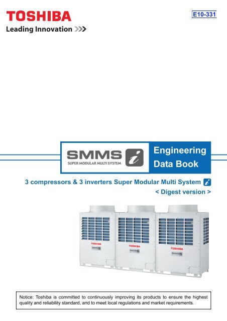
E10-331<strong>Engineering</strong><strong>Data</strong> <strong>Book</strong>3 compressors & 3 inverters Super Modular Multi System< Digest version >Notice: <strong>Toshiba</strong> is committed to continuously improving its products to ensure the highestquality and reliability standard, and to meet local regulations and market requirements.
SMMS-i <strong>Data</strong> bookContents1 Foreword ........................................................................................ 1-12 Safety caution ................................................................................. 2-13 Introduction ..................................................................................... 3-14 System overview ............................................................................ 4-14.1. OUTLINE OF TOSHIBA SMMS.......................................................................... 4-14.2. SUMMARY OF SYSTEM EQUIPMENTS........................................................... 4-24.3. List of product and combined model name......................................................... 4-34.4. Indoor unit........................................................................................................... 4-54.5. Remote controller ............................................................................................... 4-65 Basic system configuration ............................................................. 5-15.1. Basic systems..................................................................................................... 5-15.2. Fresh Air Intake Indoor Unit Type....................................................................... 5-36 Equipment selection procedure ...................................................... 6-16.1. Selection flow chart............................................................................................. 6-16.2. Operational temperature range........................................................................... 6-26.3. Combination conditions for indoor unit and outdoor unit .................................... 6-26.4. Cooling/heating capacity characteristics............................................................. 6-36.5. Selection procedure for fresh air intake indoor unit ............................................ 6-67 Refrigerant piping design .............................................................. 7-17.1. WARNINGS ON REFRIGERANT LEAKAGE ..................................................... 7-17.2. Free branching system ....................................................................................... 7-27.3. Allowable length/height difference of refrigerant piping ...................................... 7-37.4. Selection of refrigerant piping ............................................................................. 7-47.5. Charging requirement with additional refrigerant................................................ 7-58 Part Load performance ................................................................... 8-18.1. Single unit ........................................................................................................... 8-18.2. Combination........................................................................................................ 8-59 Wiring Design ................................................................................. 9-19.1. General ............................................................................................................... 9-19.2. Summary of wiring design .................................................................................. 9-19.3. Electrical wiring design ....................................................................................... 9-19.4. Outdoor unit power supply.................................................................................. 9-19.5. Indoor unit power supply..................................................................................... 9-310 Controls ........................................................................................ 10-111 Sound characteristics (NC curve) ............................................... 11-111.1. Single unit ......................................................................................................... 11-111.2. Combination...................................................................................................... 11-312 Technical Specifications ............................................................. 12-112.1. Outdoor unit...................................................................................................... 12-112.1.1 Specifications ........................................................................................................ 12-112.1.2 Dimensional drawing ............................................................................................. 12-912.1.3 Connecting diagram ............................................................................................ 12-1012.1.4 Wiring diagram .................................................................................................... 12-1112.1.5 Branch header / branch joint ............................................................................... 12-1212.2. Indoor unit....................................................................................................... 12-1312.2.1 Specifications ...................................................................................................... 12-13
SMMS-i <strong>Data</strong> book1 ForewordThe engineering data book details all relevant data, chartsand drawings to enable you to get the best performancefrom the <strong>Toshiba</strong> Super Modular Multi System i for thevarious applications.The information is aimed to assist you by providing greaterdetail of the system and the wider applications that thesystem will cover.1 -1
SMMS-i <strong>Data</strong> book2 Safety caution• Before use, read carefully through the “Safety caution” section to ensure correct operation.• The important contents concerned to the safety are described in the “Safety Cautions”.Be sure to keep them. For Indications and their meanings, see the following description.Explanation of indicationsWARNINGIndicates possibilities that a death or serious injury of personnel is caused by an incorrect handling.CAUTIONIndicates contents that an injury (* 1 ) or property damage (* 2 ) only may be caused when an incorrect work has been executed.*1: “Injury” means a hurt, a burn, or an electric shock which does not require hospitalization or a long-term going to the hospital.*2: “Property damage means an enlarged damage concerned to property, or breakage of materials.• After installation work has finished, check there is no trouble by a test operation, and explain using method andmaintenance method to the customers based on the Owner’s Manual.Please ask the customers to keep this Installation Manual together with the Owner’s Manual.WARNINGAsk a shop or a professional dealer to install the air conditioner.If you will install by yourself, a fire, an electric shock, or water leak is caused.Take measures so that the refrigerant does not exceed the limit concentration even if it leaks when installing the air conditionerin a small room.For the measures not to exceed the limit of concentration, contact the dealer. If the refrigerant leaks and it exceeds the limit ofconcentration, an accident of oxygen shortage is caused.Install the air conditioner at a place which is satisfactorily bearable to weight.If strength is insufficient, the unit may fall down resulting in human injury.Perform a specified installation work against a strong wind such as typhoon or earthquake.If the air conditioner is imperfectly installed, an accident by falling or dropping may be caused.If refrigerant gas leaks during installation work, ventilate the room.If the leaked refrigerant gas approaches to fire, noxious gas may generate.After installation work, confirm that refrigerant gas does not leak.If refrigerant gas leaks in the room, and approaches to fire such as fan heater, stove or kitchen range, generation of noxious gas may becaused.Never recover refrigerant in the outdoor unit.Be sure to use a refrigerant recovery device to recover refrigerant in reinstallation or repair work.Recovery of refrigerant in the outdoor unit is unavailable; otherwise a serious accident such as crack or human injury is caused.A person qualified for the electric work should deal with the electric construction conforming to the regulations of the localelectric company and the Installation Manual. Be sure to use the exclusive circuit.If there is capacity shortage of the power supply circuit or incomplete installation, a fire or an electric shock is caused.For cabling, use the specified cables and connect them securely so that external force of cable does not transmit to theterminal connecting section.If connection or fixing is incomplete, a fire, etc. may be caused.Be sure to connect earth wire.Do not connect earth wire to gas pipe, water pipe, lightning rod, nor earth wire of telephone.If grounding is incomplete, an electric shock is caused.CAUTIONDo not install the air conditioner at a place where combustible gas may leak.If gas leaks and is collected at surrounding the unit, the production of fire may be caused.Be sure to attach an earth leakage breaker; otherwise an electric shock may be caused.Using a torque wrench, tighten the flare nut in the specified method.If the flare nut is exceedingly tightened, the flare nut is broken and a refrigerant leakage may be caused after a long time has passed.2 -1
2 Safety caution1. WARNINGS ON REFRIGERANT LEAKAGECheck of Concentration LimitThe room in which the air conditioner is to be installedrequires a design that in the event of refrigerant gasleaking out, its concentration will not exceed a set limit.The refrigerant R410A which is used in the airconditioner is safe, without the toxicity or combustibilityof ammonia, and is not restricted by laws to be imposedwhich protect the ozone layer. However, since itcontains more than air, it poses the risk of suffocation ifits concentration should rise excessively.Suffocation from leakage of R410A is almostnonexistent. With the recent increase in the number ofhigh concentration buildings, however, the installation ofmulti air conditioner systems is on the increase becauseof the need for effective use of floor space, individualcontrol, energy conservation by curtailing heat andcarrying power etc.Most importantly, the multi air conditioner system is ableto replenish a large amount of refrigerant comparedwith conventional individual air conditioners. If a singleunit of the multi conditioner system is to beinstalled in a small room, select a suitable model andinstallation procedure so that if the refrigerantaccidentally leaks out, its concentration does not reachthe limit (and in the event of an emergency, measurescan be made before injury can occur).In a room where the concentration may exceed the limit,create an opening with adjacent rooms, or installmechanical ventilation combined with a gas leakdetection device.The concentration is as given below.Total amount of refrigerant (kg)Min. volume of the indoor unit installed room (m 3 )≤ Concentration limit (kg/m 3 )The concentration limit of R410A which is used in multiair conditioners is 0.3kg/m 3 .NOTE 2:The standards for minimum room volume are as follows.(1) No partition (shaded portion)(2) When there is an effective opening with the adjacentroom for ventilation of leaking refrigerant gas(opening without a door, or an opening 0.15% orlarger than the respective floor spaces at the top orbottom of the door).(3) If an indoor unit is installed in each partitioned roomand the refrigerant tubing is interconnected, thesmallest room of course becomes the object. Butwhen a mechanical ventilation is installedinterlocked with a gas leakage detector in thesmallest room where the density limit is exceeded,the volume of the next smallest room becomes theobject.Refrigerant pipingVerysmallroomSmallroomImportantMediumroomOutdoor unitRefrigerant pipingLarge roomIndoor unitOutdoor unitIndoor unitNOTE 1:If there are 2 or more refrigerating systems in a singlerefrigerating device, the amounts of refrigerant shouldbe as charged in each independent device.e.g., chargedamount (10kg)Outdoor unite.g.,charged amount (15kg)Room A Room B Room C Room D Room E Room FIndoor unitFor the amount of charge in this example:The possible amount of leaked refrigerant gas inrooms A, B and C is 10kg.The possible amount of leaked refrigerant gas inrooms D, E and F is 15kg.Mechanical ventilation device - Gas leak detectorNOTE 3:The minimum indoor floor area compared with theamount of refrigerant is roughly as follows: (When theceiling is 2.7m high)Min. indoor floor area40m² 35302520151050Range below thedensity limit of0.3 kg/m 3(countermeasures not needed)Range abovethe density limitof 0.3 kg/m 3(countermeasures needed)10 20 30Total amount of refrigerantkg2 -2
SMMS-i <strong>Data</strong> book3 IntroductionThe next-generation ‘-quality’ trioDedication to innovation and advanced intelligence fosters the imaginativecreativity with which we deliver total value in air conditioning systems.innovation, intelligence and imaginationIndustry-leading energy savingsEnergy-efficient performancefor greater environmentalfriendliness6.38COP5.506.195.60EER(COP/EER)765Rated50% load8HP : MMY-MAP0804HT8-E16HP : MMY-MAP1604HT8-E(HP)4.428HP3.4416HP4.068HP3.2116HP432*European modelsIndustry-leading pipe length for greater flexibilityIndustryNo.1Farthest equivalent length* As of December 2009 (according to in-house studies)Greater support for height differences between indoor unitsIndustryNo.1Height betweenindoor unitsSinglesystem*Calculated at 3.5 meters per floor* As of December 2009 (according to in-house studies)3 -1
3 IntroductionThe industry first!Introducing high-performance outdoor unitswith3 compressors *1 and3 invertersNew DC twin-rotary compressorNEWLeading the world with <strong>Toshiba</strong>’s own new DC twin-rotary compressorImproved motorefficiencyNewly designedcompression pathGreaterparts precisionNew DC twin-rotary compressorCompact and powerful magnetic rotorReduce 40%(16HP Outdoor unit)Fast-calculating vector-controlled inverterNEWAll-inverter control realizes finer control over operation to match the loadon the systemSmooth sine curveCircuit boardInfinity variable controlUltra-precise 0.1 Hz control over compressorrotation speedThe industry1st! *2(14HP, 16HP)Current-SMMSNew-SMMSi*1 14HP and 16HP models *2 As of December 2009 (according to in-house studies)3 -2
4 System overview2. SUMMARY OF SYSTEM EQUIPMENTSEquipmentOutdoor unitsCorresponding HPInverter unit5HP* 6HP* 8HP 10HP 12HP 14HP 16HPModelHeatpumpMMY- MAP0501HT8-E MAP0601HT8-E MAP0804HT8-E MAP1004HT8-E MAP1204HT8-E MAP1404HT8-E MAP1604HT8-Ename CoolingMMY- MAP0501T8-EonlyMAP0601T8-E MAP0804T8-E MAP1004T8-E MAP1204T8-E MAP1404T8-E MAP1604T8-ECooling capacity (kW) 14.0 16.0 22.4 28.0 33.5 40.0 45.0Heating capacity (kW) 16.0 18.0 25.0 31.5 37.5 45.0 50.0No. of connectableindoor units8 10 13 16 20 23 27Combination of outdoor unitsStandard modelCorresponding HP 18HP 20HP 22HP 24HP 26HP 28HP 30HP 32HPCombined MMY- AP1814HT8-E AP2014HT8-E AP2214HT8-E AP2414HT8-E AP2614HT8-E AP2814HT8-E AP3014HT8-E AP3214HT8-EModel MMY- AP1814T8-E AP2014T8-E AP2214T8-E AP2414T8-E AP2614T8-E AP2814T8-E AP3014T8-E AP3214T8-ECooling capacity (kW) 50.4 56.0 61.5 68.0 73.0 78.5 85.0 90.0Heating capacity (kW) 56.5 63.0 69.0 76.5 81.5 88.0 95.0 100.010HP 10HP 12HP 12HP 16HP 16HP 16HP 16HPCombined outdoor units8HP 10HP 10HP 12HP 10HP 12HP 14HP 16HP– – – – – – – –– – – – – – – –No. of connectableindoor units30 33 37 40 43 47 48 48Corresponding HP 34HP 36HP 38HP 40HP 42HP 44HP 46HP 48HPCombined MMY- AP3414HT8-E AP3614HT8-E AP3814HT8-E AP4014HT8-E AP4214HT8-E AP4414HT8-E AP4614HT8-E AP4814HT8-EModel MMY- AP3414T8-E AP3614HT8-E AP3814T8-E AP4014T8-E AP4214T8-E AP4414T8-E AP4614T8-E AP4814T8-ECooling capacity (kW) 96.0 101.0 106.5 112.0 118.0 123.5 130.0 135.0Heating capacity (kW) 108.0 113.0 119.5 127.0 132.0 138.0 145.0 150.012HP 12HP 16HP 16HP 16HP 16HP 16HP 16HPCombined outdoor units12HP 12HP 12HP 12HP 14HP 16HP 16HP 16HP10HP 12HP 10HP 12HP 12HP 12HP 14HP 16HP– – – – – – – –No. of connectableindoor units48 48 48 48 48 48 48 48High efficiency modelCorresponding HP 16HP 24HP 26HP 28HP 30HP 32HP 34HP 36HPCombined MMY- AP1624HT8-E AP2424HT8-E AP2624HT8-E AP2824HT8-E AP3024HT8-E AP3224HT8-E AP3424HT8-E AP3624HT8-EModel MMY- AP1624T8-E AP2424T8-E AP2624T8-E AP2824T8-E AP3024T8-E AP3224T8-E AP3424T8-E AP3624T8-ECooling capacity (kW) 45.0 68.0 73.0 78.5 85.0 90.0 96.0 101.0Heating capacity (kW) 50.0 76.5 81.5 88.0 95.0 100.0 108.0 113.08HP 8HP 10HP 10HP 10HP 8HP 10HP 10HPCombined outdoor units8HP 8HP 8HP 10HP 10HP 8HP 8HP 10HP– 8HP 8HP 8HP 10HP 8HP 8HP 8HP– – – – – 8HP 8HP 8HPNo. of connectableindoor units27 40 43 47 48 48 48 48Corresponding HP 38HP 40HP 42HP 44HP 46HP 48HPCombined MMY- AP3824HT8-E AP4024HT8-E AP4224HT8-E AP4424HT8-E AP4624HT8-E AP4824HT8-EModel MMY- AP3824T8-E AP4024T8-E AP4224T8-E AP4424T8-E AP4624T8-E AP4824T8-ECooling capacity (kW) 106.5 112.0 118.0 123.5 130.0 135.0Heating capacity (kW) 119.5 127.0 132.0 138.0 145.0 150.010HP 10HP 12HP 12HP 12HP 12HPCombined outdoor units10HP 10HP 10HP 12HP 12HP 12HP10HP 10HP 10HP 10HP 12HP 12HP8HP 10HP 10HP 10HP 10HP 12HPNo. of connectableindoor units48 48 48 48 48 48Branching joints and headers*1 “Capacity code” can be obtained by the lists on next page and after the next page.(Capacity code is not actual capacity.)*2 If total capacity code value of indoor unit exceeds that of outdoor unit, apply capacity code of outdoor unit.*3 When using Y-shape branching joint for 1st branching, select according to the capacity code of the outdoor unit.*4 Max. capacity code of 6.0 in total can be connected.*5 If capacity code of outdoor unit is 26 or more, it is not used for 1st branching.4 -2* SMMS outdoor unitAppearanceModel name Usage (Classification according to indoor unit capacity code (* 1 )) AppearanceRBM-BY55E Total below 6.4Y-shape branching joint (* 3 )RBM-BY105E Total 6.4 or more and below 14.2 (* 2 )RBM-BY205E Total 14.2 or more and below 25.2 (* 2 )RBM-BY305E Total 25.2 or more (* 2 )4-branching header (* 4 )RBM-HY1043E Total below 14.2RBM-HY2043E Total 14.2 or more and below 25.2Max.4 branchesRBM-HY1083E Total below 14.2Max.8 branches8-branching header (* 4 ) (* 5 )RBM-HY2083E Total 14.2 or more and below 25.2Branching joint for connectionof outdoor units(1set of 1type of Y-shape jointpipe and 2types of T-joint pipesas described right.)RBM-BT14ERBM-BT24EUsage Piping at gas side (Y-shape) Piping at liquid side (T-shape) Balance pipe (T-shape)ø19.1ø9.5ø28.6Total below 26 ø31.8ø25.4ø19.1 ø19.1ø9.5 ø9.5Total 26 or moreø38.1ø38.1ø28.6ø22.2ø22.2ø22.2ø9.5ø9.5ø9.5
4 System overviewCooling Only modelHP(Capacitycode)Model nameMMY-* : SMMS outdoor unitNo. ofcombinedunitsInverter 5HPMMY-UsedQtyInverter 6HPMMY-UsedQtyInverter 8HPMMY-1. Allocation standard of model nameUsedQtyInverter 10HPMMY-UsedQtyInverter 12HPMMY-UsedQtyInverter 14HPMMY-UsedQtyInverter 16HPMMY-Standard model5HP(5)* MAP0501T8-E 1 MAP0501T8-E 16HP(6)* MAP0601T8-E 1 MAP0601T8-E 18HP(8) MAP0804T8-E 1 MAP0804T8-E 110HP(10) MAP1004T8-E 1 MAP1004T8-E 112HP(12) MAP1204T8-E 1 MAP1204T8-E 114HP(14) MAP1404T8-E 1 MAP1404T8-E 116HP(16) MAP1604T8-E 1 MAP1604T8-E 118HP(18) AP1814T8-E 2 MAP0804T8-E 1 MAP1004T8-E 120HP(20) AP2014T8-E 2 MAP1004T8-E 222HP(22) AP2214T8-E 2 MAP1004T8-E 1 MAP1204T8-E 124HP(24) AP2414T8-E 2 MAP1204T8-E 226HP(26) AP2614T8-E 2 MAP1004T8-E 1 MAP1604T8-E 128HP(28) AP2814T8-E 2 MAP1204T8-E 1 MAP1604T8-E 130HP(30) AP3014T8-E 2 MAP1404T8-E 1 MAP1604T8-E 132HP(32) AP3214T8-E 2 MAP1604T8-E 234HP(34) AP3414T8-E 3 MAP1004T8-E 1 MAP1204T8-E 236HP(36) AP3614T8-E 3 MAP1204T8-E 338HP(38) AP3814T8-E 3 MAP1004T8-E 1 MAP1204T8-E 1 MAP1604T8-E 140HP(40) AP4014T8-E 3 MAP1204T8-E 2 MAP1604T8-E 142HP(42) AP4214T8-E 3 MAP1204T8-E 1 MAP1404T8-E 1 MAP1604T8-E 144HP(44) AP4414T8-E 3 MAP1204T8-E 1 MAP1604T8-E 246HP(46) AP4614T8-E 3 MAP1404T8-E 1 MAP1604T8-E 248HP(48) AP4814T8-E 3 MAP1604T8-E 3High efficiency model16HP(16) AP1624T8-E 2 MAP0804T8-E 224HP(24) AP2424T8-E 3 MAP0804T8-E 326HP(26) AP2624T8-E 3 MAP0804T8-E 2 MAP1004T8-E 128HP(28) AP2824T8-E 3 MAP0804T8-E 1 MAP1004T8-E 230HP(30) AP3024T8-E 3 MAP1004T8-E 332HP(32) AP3224T8-E 4 MAP0804T8-E 434HP(34) AP3424T8-E 4 MAP0804T8-E 3 MAP1004T8-E 136HP(36) AP3624T8-E 4 MAP0804T8-E 2 MAP1004T8-E 238HP(38) AP3824T8-E 4 MAP0804T8-E 1 MAP1004T8-E 340HP(40) AP4024T8-E 4 MAP1004T8-E 442HP(42) AP4224T8-E 4 MAP1004T8-E 3 MAP1204T8-E 144HP(44) AP4424T8-E 4 MAP1004T8-E 2 MAP1204T8-E 246HP(46) AP4624T8-E 4 MAP1004T8-E 1 MAP1204T8-E 348HP(48) AP4824T8-E 4 MAP1204T8-E 4UsedQtyMMY_ E_ M AP T 8Power supply specifications, 3Ø 380-400-415V, 50Hz ....... 8T: Capacity variable unitDevelopment series No.0 : Single model, 1: Standard model, 2 : High efficiency modelCapacity rank HPRefrigerant R410AM: Single module unit, No mark: Combined Model nameModular Multi2. Rang of combined capacityNo. of combined units: 1 to 4 unitsCapacity of combined units: 16 HP(16type) to 48 HP(48type)3. Rated conditionsCooling: Indoor air temperature 27ºC DB/19ºC WB, Outdoor air temperature 35ºC DB4 -4
SMMS-i <strong>Data</strong> book5 Basic system configuration1. Basic systems8 HP system• Max. indoor unit : 13 units• Capacity code of indoor unit : Min. : 4Max. : 10.8Outdoor unit8HPCapacity codeover the branch(0.8 + 0.8 = 1.6)10.4 4.8 4.0 3.2 2.4 1.6Indoor unitdesignationCapacity codeTotal 10.4No. of total unitsCapacityCode13007(0.8)007(0.8)007(0.8)007(0.8)007(0.8)007(0.8)5.6 4.8 4.0 3.2 2.4 1.6 0.8Indoor unitRemotecontroller007(0.8)007(0.8)007(0.8)007(0.8)007(0.8)007(0.8)007(0.8)20 HP system• Max. indoor unit : 33 units• Capacity code of indoor unit : Min. : 10Max. : 27Outdoor unitCapacity codeTotal 26.75No. of total units1910HP 10HP1026.75 10.25 8.256.25 5.0 3.75 2.5018(2.0)018(2.0)012(1.25)012(1.25)012(1.25)012(1.25)012(1.25)16.58.25 6.25 5.0 3.75 2.5018(2.0)012(1.25)012(1.25)012(1.25)012(1.25)012(1.25)8.25 6.25 5.0 3.75 2.5Indoor unitRemotecontroller018(2.0)012(1.25)012(1.25)012(1.25)012(1.25)012(1.25)5 -1
5 Basic system configuration40 HP system (Standard model)• Max. indoor unit : 48 units• Capacity code of indoor unit : Min. : 20Max. : 54Capacity codeTotal 53.75No. of total units32Outdoor unit16HP 12HP 12HP40281653.75 14.0 13.0 12.0 11.0 9.75 8.5 6.5009009009012012018024036(1)(1)(1)(1.25)(1.25)(2.0)(2.5)(4)39.7513.25 12.25 11.25 10.25 9.0 7.75 6.5009009009012012012024036(1)(1)(1)(1.25)(1.25)(1.25)(2.5)(4)26.513.25 12.25 11.25 10.25 9.0 7.75 6.5009009009012012012024036(1)(1)(1)(1.25)(1.25)(1.25)(2.5)(4)13.25 12.25 11.25 10.25 9.0 7.75 6.5Indoor unit009009009012012012024036Remotecontroller(1)(1)(1)(1.25)(1.25)(1.25)(2.5)(4)5 -2
5 Basic system configuration2. Fresh Air Intake Indoor Unit Type34 HP systemConnecting limitation• The total capacity of the fresh air intake units and the indoor units is restricted to 80to 100% against the capacity of the outdoor units.• Up to two fresh air intake units can be connected on one line of the multi system.• The allowable total capacity of fresh air intake units shall be 30% or less againstthe total capacity of the indoor units (including the fresh air intake units).• The fresh air intake units only cannot connected.Capacity codeTotal 34No. of total units8Outdoor unit12HP 12HP 10HP3424 20 16 12 8036(4)036(4)036(4)036(4)036(4)036 Indoor unit(4)10Remotecontroller024 024 Fresh Air Intake Indoor unit(5) (5)Remotecontroller5 -3
SMMS-i <strong>Data</strong> book6 Equipment selection procedure1. Selection flow chart1 Determination of indoor air-conditioning load at each room.2 Preliminary selection of indoor units in the standard capacity no lessthan air-conditioning load at each room.3 Calculate corrected capacity A of each indoor unit by correcting ofindoor temperature for the standard capacity of each indoor unit.(Referto Chart [1])4 Preliminary selection of outdoor unit in the standard capacity no lessthan total values of corrected capacity A in indoor units. At the same time,check both connectable indoor units number and the outdoor unitdiversity(Connected ratio of indoor units to outdoor units) for thespecifications.5 Calculate corrected capacity B of each indoor unit by following 2 steps.Step1:Find the correction value of "Connecting pipe length and lift" byboth the longest length and the largest height with selected pipingcondition at 4 or 4’.(Refer to Chatrt [3])Step2:Calculate by multiplying the value of step1 by corrected capacity A.2’ Increase of indoorunit capacity at objectroom against airconditioningload6 Corrected capacity B of indoorunit >= air-conditioning load (for Allrooms)OKNGYES7 Find correction values of below items for the standard capacity ofoutdoor unit selected at 4 or 4’.Then determination of total corrected capacity of the selected outdoor unitby all multiplying.-Correction of indoor temperature condition(Refer to Chart [1])-Correction of outdoor temperature condition(Refer to Chart [2])-Correction of connecting pipe length and lift between indoor and outdoorunits by both the longest length and the largest height (Refer to Chart [3])-Correction of outdoor unit diversity in only over 100%(Refer to Chart [4])-Correction of frost condition on outdoor heat exchanger when in heating(Refer to Chart [5])NO5’ The correction characteristicof "connecting pipe length andlift"(Graph [3]) betweenincreased outdoor unit at ?’and preliminary selectedoutdoor unit at ? is different.(The both graphs aredifferent.)8 Calculate corrected capacity C of each indoor unit by multiplying thetotal corrected capacity of outdoor unit at 7by proportional division ofeach indoor unit standard capacity for total standard capacity of all indoorunits.5’ Increase of outdoor unit capacity.At the same time, check bothconnectable indoor units numberand the outdoor unit diversity9 Corrected capacity C of indoorunit >= air-conditioning load (for Allrooms)NGOKend6 -1
6 Equipment selection procedure2. Operational temperature rangeOutdoor air dry bulb temp. (°C)454035302520151050-5-101015CoolingContinuouslyoperablerange20Range for pulldown operation25 28Indoor air wet bulb temp. (°C)30Outdoor air wet bulb temp. (°C)20151050-5-10-15Range for warmingup operationHeatingContinuouslyoperablerange-205 10 15 20 25 30Indoor air dry bulb temp. (°C)3. Combination conditions for indoor unit and outdoor unit1. For indoor unit, the capacity code is decided for each capacity rank.Capacity rank type 007 009 012 015 018 024 027 030 036 048 056 072 096Capacity code 0.8 1 1.25 1.7 2 2.5 3 3.2 4 5 6 8 10NOTE:Capacity rank: Correspondence to Btu/h. Capacity code: Correspondence to Horsepower.2. For outdoor unit, maximum No. of connectable indoor units and total capacity code of indoor units are decided.Outdoor unit (Heat pump) Outdoor unit (Cooling only) Capacity code of outdoor unit Max. No. of indoor unitsTotal capacity code ofindoor unitsStandard modelMMY-MAP0501HT8-E* MMY-MAP0501T8-E* 5 8 2.5 to 6.75MMY-MAP0601HT8-E* MMY-MAP0601T8-E* 6 10 3 to 8.1MMY-MAP0804HT8-E MMY-MAP0804T8-E 8 13 4 to 10.8MMY-MAP1004HT8-E MMY-MAP1004T8-E 10 16 5 to 13.5MMY-MAP1204HT8-E MMY-MAP1204T8-E 12 20 6 to 16.2MMY-MAP1404HT8-E MMY-MAP1404T8-E 14 23 7 to 18.9MMY-MAP1604HT8-E MMY-MAP1604T8-E 16 27 8 to 21.6MMY-AP1814HT8-E MMY-AP1814T8-E 18 30 9 to 24.3MMY-AP2014HT8-E MMY-AP2014T8-E 20 33 10 to 27MMY-AP2214HT8-E MMY-AP2214T8-E 22 37 11 to 29.7MMY-AP2414HT8-E MMY-AP2414T8-E 24 40 12 to 32.4MMY-AP2614HT8-E MMY-AP2614T8-E 26 43 13 to 35.1MMY-AP2814HT8-E MMY-AP2814T8-E 28 47 14 to 37.8MMY-AP3014HT8-E MMY-AP3014T8-E 30 48 15 to 40.5MMY-AP3214HT8-E MMY-AP3214T8-E 32 48 16 to 43.2MMY-AP3414HT8-E MMY-AP3414T8-E 34 48 17 to 45.9MMY-AP3614HT8-E MMY-AP3614T8-E 36 48 18 to 48.6MMY-AP3814HT8-E MMY-AP3814T8-E 38 48 19 to 51.3MMY-AP4014HT8-E MMY-AP4014T8-E 40 48 20 to 54MMY-AP4214HT8-E MMY-AP4214T8-E 42 48 21 to 56.7MMY-AP4414HT8-E MMY-AP4414T8-E 44 48 22 to 59.4MMY-AP4614HT8-E MMY-AP4614T8-E 46 48 23 to 62.1MMY-AP4814HT8-E MMY-AP4814T8-E 48 48 24 to 64.8High efficiency modelMMY-AP1624HT8-E MMY-AP1624T8-E 16 27 8 to 21.6MMY-AP2424HT8-E MMY-AP2424T8-E 24 40 12 to 32.4MMY-AP2624HT8-E MMY-AP2624T8-E 26 43 13 to 35.1MMY-AP2824HT8-E MMY-AP2824T8-E 28 47 14 to 37.8MMY-AP3024HT8-E MMY-AP3024T8-E 30 48 15 to 40.5MMY-AP3224HT8-E MMY-AP3224T8-E 32 48 16 to 43.2MMY-AP3424HT8-E MMY-AP3424T8-E 34 48 17 to 45.9MMY-AP3624HT8-E MMY-AP3624T8-E 36 48 18 to 48.6MMY-AP3824HT8-E MMY-AP3824T8-E 38 48 19 to 51.3MMY-AP4024HT8-E MMY-AP4024T8-E 40 48 20 to 54MMY-AP4224HT8-E MMY-AP4224T8-E 42 48 21 to 56.7MMY-AP4424HT8-E MMY-AP4424T8-E 44 48 22 to 59.4MMY-AP4624HT8-E MMY-AP4624T8-E 46 48 23 to 62.1MMY-AP4824HT8-E MMY-AP4824T8-E 48 48 24 to 64.8* : SMMSThe unit will operate down to an outdoor temperature of-20°C, however considerable performance decrease will be expected below -15°C.Therefore please consider installation location/surroundings and system designwhen expected to operate between -15°C and -20°C.6 -250 to 135% of outdoor unit capacity
6 Equipment selection procedure4. Cooling/heating capacity characteristics1. Correction charts for cooling capacity calculation[1] Indoor air wet bulb temperature vs. capacitycorrection value1.2[2] Outdoor air dry bulb temperature vs.capacitycorrection valueCapacity correction value1.11.00.90.81520 24Indoor air wet bulb temp. (°C)[3] Connecting pipe length and lift difference betweenindoor and outdoor units vs. capacity correction valueHeight of outdoor unit H (m)706050403020100-10-20-30-40hohc100%hb95%l'ohaOutdoor unit (A1)97.5%92.5%Outdoor unitL' is the longest one of(l'o + l'a, l'o + l'b, l'o + l'c)H = ho +(Largest one of ha, hb, and hc)90%87.5%l'al'bl'c85%AB Indoor unitC82.5%0 10 20 30 40 50 60 70 80 90100 110 120130 140 150160 170 180190 200 210Pipe length (Equivalent length) L’ (m)80%77.5%75%72.5%Capacity correction valueHeight of outdoor unit H (m)1.21.11.00.9-10 -5 0 10 15 20 25 30 35 40 43Outdoor air dry bulb temp. (°C)HPStandard model High efficiency modelPipe length Graph Pipe length Graph8 210 A110 210 B112 210 A114 210 A116 210 A1 220 A218 220 B220 220 B222 220 A224 220 A2 235 A326 220 B2 235 B328 220 B2 235 B330 220 B2 235 B332 220 B2 235 B334 235 B3 235 B336 235 A3 235 A338 235 B3 235 B340 235 B3 235 B342 235 B3 235 B344 235 B3 235 B346 185 C1 185 C148 185 C1 185 C1706050403020100-10-20-30-40Outdoor unit (A2)100%97.5%95%92.5%90%87.5%85%82.5%0 10 20 30 40 50 60 70 80 90 100 110 12013014015016017018019020021022080%77.5%75%Pipe length (Equivalent length) L’ (m)72.5%70%Height of outdoor unit H (m)706050403020100-10-20-30-40Outdoor unit (A3)100%97.5%95%92.5%90%87.5%85%82.5%0 10 20 30 40 50 60 70 80 90 100 110 120130 140 150160 170 180190 200 210 220 23080%77.5%75%Pipe length (Equivalent length) L’ (m)72.5%70%Height of outdoor unit H (m)706050403020100-10-20-30-40Outdoor unit (B1)100%97.5%95%92.5%90%87.5%85%82.5%80%0 10 20 30 40 50 60 70 80 90100 110 120130 140 150160 170 180190 200 210Pipe length (Equivalent length) L’ (m)77.5%75%72.5%70%67.5%6 -3
6 Equipment selection procedureHeight of outdoor unit H (m)Outdoor unit (B2)706050403020100-10-20-30-400 10 20 30 40 50 60 70 80 90 100 110 120130 140 150160 170 180190 200 210 220Pipe length (Equivalent length) L’ (m)100%97.5%95%92.5%90%87.5%85%82.5%80%77.5%75%72.5%70%67.5%Height of outdoor unit H (m)706050403020100-10-20-30-40Outdoor unit (B3)100%97.5%95%92.5%90%87.5%85%82.5%80%0 10 20 30 40 50 60 70 80 90 100 110 120130 140 150160 170 180190 200 210 220 23077.5%75%72.5%Pipe length (Equivalent length) L’ (m)70%67.5%65%Height of outdoor unit H (m)Outdoor unit (C)706050403020100-10-20-30-400 10 20 30 40 50 60 70 80 90 100 110 120 130 140 150 160 170 180Pipe length (Equivalent length) L’ (m)100%97.5%95%92.5%90%87.5%85%82.5%80%77.5%75%72.5%70%67.5%[4]* Correction of outdoor unit diversity1.21.0Correction0.80.60.40.2020 40 60 80 100 120 135Standard capacity ratioIndoor units total capacity ratio (%)*: Coefficient to use for the correction of the outdoor unit capacity when the total capacity of the indoor units are not equal to theoutdoor unit capacity.6 -4
6 Equipment selection procedure2. Correction charts for heating capacity calculation[1] Indoor air dry bulb temperature vs. capacity correction value [2] Outdoor air wet bulb temperature vs. capacity correction value1.2Capacity correction value1.11.00.90.815 20 24Indoor air dry bulb temp. (°C)[3] Connecting pipe length and lift difference between indoorand outdoor units vs. capacity correction valueOutdoor unitCapacity correction value1.21.11.00.90.80.70.60.50.4-20 -15 -10 -5 0 5 10 15Outdoor air wet bulb temp. (°C)hol'oL' is the longest one of(l'o + l'a, l'o + l'b, l'o + l'c)H = ho +(Largest one of ha, hb, and hc)Height of outdoor unit H (m)hchbhal'al'bl'cAB Indoor unitC706050403020100-10-20-30-400 10 20 30 40 50 60 70 80 90 100 110 120130 140 150160 170 180190 200 210 220 230100%99%98%97%Outdoor unit (8 to 48HP)96%95%94%93%92%91%90%89%Pipe length (Equivalent length) L’ (m)88%87%86%85%[4]* Correction of outdoor unit diversity*: Coefficient to use for the correction of the outdoor unit capacity when the total capacity of the indoor units are not equal to theoutdoor unit capacity.3. Capacity correction in case of frost on the outdoor heat exchanger when in heatingCorrect the heating capacity when frost can be found on the outdoor heat exchanger.Heating capacity = Capacity after correction of outdoor unit x Correction value of capacity resulted from frost(Capacity after correction of outdoor unit: Heating capacity calculated in the above item 2.)[5] Capacity correction in case of frost on the outdoor heat exchangerCapacity correction value1.00.94. Rated conditionsCooling: Indoor air temperature 27°C DB/19°C WB, Outdoor air temperature 35°C DBHeating: Indoor air temperature 20°C DB, Outdoor air temperature 7°C DB/6°C WBCorrection0.8-15 -10 -5 0 5Outdoor air wet bulb temp. (°C)1.21.00.80.60.40.2020 40 60 80 100 120 135Standard capacity ratioIndoor units total capacity ratio (%)6 -5
6 Equipment selection procedure5. Selection procedure for fresh air intake indoor unit5.1 Selection flow chart1. Decisions of both air volume for fresh air intake and static pressure of ductIt is necessary to calculate “required ventilatory volume” to decide the air volume.Be sure to consider the balance of air supply and exhaust.2. Decisions of fresh air intake indoor unit by necessary air volume and externalstatic pressure3. Temporary grouping of outdoor units and normal indoor units + fresh air intakeindoor unitsGrouping limitation*1 : The system is SMMS, is not SHRM(heat recovery).*2 : Up to two fresh air intake indoor units on one line of the multi system.*3 : The allowable total capacity of fresh air intake units shall be 30% or less against the totalcapacity of the indoor units(including the fresh air intake units).*4 : The total capacity of the fresh air intake units and the indoor units is restricted to 80 to100% against the capacith capacity of the outdoor units.*5 : The fresh air intake units only cannot connected.4. Check of piping length and the height difference for between outdoor units andnormal indoor units + fresh air intake indoor units.5. Capacity correction with design indoor temperature and outdoor temperature6. Check of temporary groupingoutdoor units and normal indoorunits + fresh air intake indoor unitsNo goodOK7. Decision of combination between outdoor units and normal indoor units + freshair intake indoor unitsend6 -6
6 Equipment selection procedure5.2 Operatable temperature range and discharge temperature set upOperatable temperature rangeCOOL modeFresh air temp.°CTs : Setup Temp.–10 0 10 20 30 4050Ts540FANCOOLOperable mode and sidecharge temp setup rangeOperation mode At shipment from factory Setup rangeCOOL 18°C 16 to 27°CHEAT 25°C 16 to 27°CTs + 3°CHEAT mode–5HEATTsFAN43Ts – 3°C• In cooling operation, if the temperature is below 5°C, the operation stops automatically. (FAN stop)• In heating operation, if the temperature is below –5°C, the operation stops automatically. (FAN stop)(To protect the refrigerant cycle)5.3 Calculation of required ventilatory volumeThe required ventilatory volume (air supply quantity) is calculated depending on the ventilation purpose or thenumber of ventilation ducts.Ex. Calculation method based on a general living room under Japanese Building Standard LawAvailable amount of ventilation V [m 3 /h]V = 20 Af/NAf : Floor space of the living room m 2N : Occupation area per room m 2If N > 10, please set N to 10.(In the case of a living room of the special building, please change 10m 2 to 3m 2 as N.)Af/N means number of people in the living room.So if “X” as number of people in the living room is settled, V is able to define by the below expressionV = 20 x XThis expression is based on Japanese Building Standard Law and the coefficient “20” (unit : m 3 /h) is based onexhaust volume of carbon dioxide by breathing per person who is quietly sitting adult male.Although the coefficient is not always enough ventilatory volume.In fact in ASHRAE (American Society of Heating Refrigerating and Air-Conditioning Engineers),it shows 30 m 3 /h per person as its guideline in consideration of smells of the cigarette and so on.Please calculate the required ventilatory volume with meeting for local regulations, market requirementsand customer’s purpose.6 -7
SMMS-i <strong>Data</strong> book7 Refrigerant piping design1. WARNINGS ON REFRIGERANT LEAKAGECheck of Concentration LimitThe room in which the air conditioner is to be installedrequires a design that in the event of refrigerant gasleaking out, its concentration will not exceed a set limit.The refrigerant R410A which is used in the airconditioner is safe, without the toxicity or combustibilityof ammonia, and is not restricted by laws to be imposedwhich protect the ozone layer. However, since itcontains more than air, it poses the risk of suffocation ifits concentration should rise excessively.Suffocation from leakage of R410A is almostnonexistent. With the recent increase in the number ofhigh concentration buildings, however, the installation ofmulti air conditioner systems is on the increase becauseof the need for effective use of floor space, individualcontrol, energy conservation by curtailing heat andcarrying power etc.Most importantly, the multi air conditioner system is ableto replenish a large amount of refrigerant comparedwith conventional individual air conditioners. If a singleunit of the multi conditioner system is to beinstalled in a small room, select a suitable model andinstallation procedure so that if the refrigerantaccidentally leaks out, its concentration does not reachthe limit (and in the event of an emergency, measurescan be made before injury can occur).In a room where the concentration may exceed the limit,create an opening with adjacent rooms, or installmechanical ventilation combined with a gas leakdetection device.The concentration is as given below.Total amount of refrigerant (kg)Min. volume of the indoor unit installed room (m 3 )≤ Concentration limit (kg/m 3 )The concentration limit of R410A which is used in multiair conditioners is 0.3kg/m 3 .NOTE 2:The standards for minimum room volume are as follows.(1) No partition (shaded portion)(2) When there is an effective opening with the adjacentroom for ventilation of leaking refrigerant gas(opening without a door, or an opening 0.15% orlarger than the respective floor spaces at the top orbottom of the door).(3) If an indoor unit is installed in each partitioned roomand the refrigerant tubing is interconnected, thesmallest room of course becomes the object. Butwhen a mechanical ventilation is installedinterlocked with a gas leakage detector in thesmallest room where the density limit is exceeded,the volume of the next smallest room becomes theobject.Refrigerant pipingVerysmallroomSmallroomImportantMediumroomOutdoor unitRefrigerant pipingLarge roomIndoor unitOutdoor unitIndoor unitNOTE 1:If there are 2 or more refrigerating systems in a singlerefrigerating device, the amounts of refrigerant shouldbe as charged in each independent device.e.g., chargedamount (10kg)Outdoor unite.g.,charged amount (15kg)Room A Room B Room C Room D Room E Room FIndoor unitFor the amount of charge in this example:The possible amount of leaked refrigerant gas inrooms A, B and C is 10kg.The possible amount of leaked refrigerant gas inrooms D, E and F is 15kg.Mechanical ventilation device - Gas leak detectorNOTE 3:The minimum indoor floor area compared with theamount of refrigerant is roughly as follows: (When theceiling is 2.7m high)Min. indoor floor area40m² 35302520151050Range below thedensity limit of0.3 kg/m 3(countermeasures not needed)Range abovethe density limitof 0.3 kg/m 3(countermeasures needed)10 20 30Total amount of refrigerantkg7 -1
7 Refrigerant piping design2. Free branching system[1] Line branching system[2] Header branching system[3] Header branching system after line branching[4] Line branching system after header branching[5] Header branching system after header branchingThe above five branching systems enable to dramatically increase the flexibility of refrigerant piping design.Line branchingsystemIndoor unitOutdoor unitBranching jointRemotecontrollerOutdoor unitHeaderbranchingsystemBranching headerIndoor unitRemote controllerOutdoor unitHeaderbranchingsystem after linebranchingIndoor unitBranching jointRemotecontrollerLine branchingsystem afterheaderbranchingOutdoor unitBranching headerHeaderbranchingsystem afterheaderbranchingIndoorunitRemotecontrollerBranchingjoint7 -2
7 Refrigerant piping design3. Allowable length/height difference of refrigerant pipingDFollowerunit 3T-shape branching joint for liquid pipeY-shape branching joint for gas pipeHeightdifferencebetweenoutdoorunitsH3 5mOutdoor unitAHeaderunitLaBFollowerunit 1LbCFollowerunit 2LcConnectingpiping ofoutdoor unitLdOKOKHeightdifferencebetweenoutdoorunitsH1 70mMainpipingL1LA LBMain connecting piping between outdoor units1st branchingsectionY-shape branchingjoint for gas pipeBranching piping L2Connecting piping of indoor unitaT-shape branchingjoint for liquid pipeNO GOODNOTE:T-shape branching joint of is prohibited.BranchingheaderL7b c d eOKNOTE:Incase of 5 & 6 HP SMMS, apply the piping rules forlength/height of SMMS.L3Indoor unitEquivalent length corresponded to farthest piping L 235 mEquivalent length corresponded to farthest piping after 1st branching LiL4L5L6Y-joint90 mHeight differencebetween indoorunitsH2 40mfg h i jSystem restrictionsMax. No. of combined outdoor units4 unitsMax. capacity of combined outdoor units 48 HPMax. No. of connected indoor units 48 unitsMax. capacity of combined H2 15 135%indoor unitsH2 > 15 105%Note 1) Combination of outdoor units: Header unit (1 unit) + Follower units (0 to 3 units).Header unit is the outdoor unit nearest to the connected indoor units.Note 2) Install the outdoor units in order of capacity.(Header unit ≥ Follower unit 1 ≥ Follower unit 2 ≥ Follower unit 3)Note 3) Use Y-shape branching joint in connecting of gas pipe for outdoor unit, and install horizontally.Note 4) Piping to indoor units shall be perpendicular to piping to the header outdoor unit as .Do not connect piping to indoor units in the same direction of header outdoor unit as T-shapebranching joint for liquid pipe of .Allowable length and height difference of refrigerant pipingPiping lengthDifference inheightTotal extension of pipe(Liquid pipe, real length)Farthest piping Length L (* 1 )Equivalent length of farthest pipingfrom 1st branching Li (* 1 )Equivalent length of farthest pipingbetween outdoor units LO (* 1 )Indoor unitAllowable valuePiping sectionBelow 34HP 300m LA + LB + La + Lb + Lc + Ld + L1 + L2 + L3 + L4+ L5 +34HP or more500mL6 + L7 + a + b + c + d + e + f + g + h + i + jActual pipe length190mEquivalent length235mLA + LB + Ld + L1 + L3 + L4 + L5 + L6 + j90m (* 2 )L3 + L4 + L5LA + LB + Ld(LA + Lb, LA + LB + Ld)25mMax. equivalent length of main piping Actual pipe length 100m (*3 )Equivalent length 120m (* 3 )L1Max. equivalent length of outdoor unit connecting piping 10m Ld(La, Lb, Lc)Max. real length of indoor unit connecting piping 30m a, b, c, d, e, f, g, h, i, jMax. equivalent length between branches 50m L2, L3, L4, L5, L6, L7Height between indoor and outdoor units H1 Upper outdoor unit 70m (*4 ) –Lower outdoor unit 40m (* 5 ) –Height between indoor units H2 40m –Height between outdoor units H3 5m –(*1) : (D) is outdoor unit furthest from the 1st branch and (j) is the indoor unit furthest from the 1st branch.(*2) : If the height difference (H1) between indoor and outdoor unit exceeds 3m, set 65m or less.(*3) : If the max. combined outdoor unit capacity is 46HP or more, then max. equivalent length is 70m or less (real length is 50m or less).(*4) : If the height difference (H2) between indoor units exceeds 3m, set 50m or less.(*5) : If the height difference (H2) between indoor units exceeds 3m, set 30m or less.7 -3
7 Refrigerant piping design4. Selection of refrigerant pipingBranching piping6 Header branching pipeFollowerunit 3Followerunit 2Followerunit 1Header unitIndoor unit connecting piping4Outdoorunit45 5 55 51 1 1 11Outdoor unitconnectingpiping2 2 72 2 7Main connectingpiping betweenoutdoor unitsBalance pipeø9.511st branchingsection3 Main pipingBranching joint foroutdoor unit46Y-shapebranchingjointIndoor unitconnecting piping44 4Indoor unit5 5 5 5 512Pipe size of outdoor unit (Table 1)Model name MMY- Gas side Liquid sideMAP0804* ø22.2 ø12.7MAP1004* ø22.2 ø12.7MAP1204* ø28.6 ø12.7MAP1404* ø28.6 ø15.9MAP1604* ø28.6 ø15.9Connecting pipe size between outdoor units (Table 2)Total capacity code of outdoor units atLiquidGas sidedownstream side * 1side16 to below 22 ø28.6 ø15.922 to below 26 ø34.9 ø15.926 to below 36 ø34.9 ø19.136 or more ø41.3 ø22.23Size of main pipe (Table 3)Total capacity code of alloutdoor units * 1 Gas side Liquid side8 to below 12 ø22.2 ø12.712 to below 14 ø28.6 ø12.714 to below 22 ø28.6 ø15.922 to below 36 ø34.9 ø19.136 to below 46 ø41.3 ø22.246 or more * 7 ø41.3 ø22.2Determine thickness of the main pipe according to capacity of the outdoor units.4Pipe size between branching sections (Table 4)* 5Balancepipeø9.5Total capacity code of indoorunits at downstream side * 1 Gas side Liquid side2.4 or less ø12.7 ø9.52.4 to below 6.4 ø15.9 ø9.56.4 to below 12.2 ø22.2 ø12.712.2 to below 20.2 ø28.6 ø15.920.2 to below 35.2 ø34.9 ø19.135.2 or more ø41.3 ø22.2If the total capacity code value of indoor units exceeds that of the outdoor units,apply the capacity code of outdoor units.5 Piping of indoor unit (Table 5)Capacity rank Gas side Liquid side007 type to Actual length 15m or less ø9.5 ø6.4012 type Actual length exceeds 15m ø12.7 ø6.4015 type to 018 type ø12.7 ø6.4024 type to 056 type ø15.9 ø9.5072 type to 096 type ø22.2 ø12.7Indoor unit6 Selection of branching section (Table 6)Total capacity code of indoor unit * 1 Model namejoint * 2 * 3 14.2 to below 25.2 RBM-BY205EBelow 6.4 RBM-BY55EY-shape branching6.4 to below 14.2 RBM-BY105E25.2 or more RBM-BY305E* 2 * 3 * 6 For 8Below 14.2 RBM-HY1083EFor 4Below 14.2 RBM-HY1043EBranching header branching 14.2 to below 25.2 RBM-HY2043Ebranching 14.2 to below 25.2 RBM-HY2083E7Selection of branching joint for outdoor unit (Table 7)Branchingjoint foroutdoorunitTotalcapacitycode ofoutdoor unitBelow 2626 or moreGas(Y-shape)ø31.8ø38.1ø28.6ø25.4ø38.1ø28.6JointsLiquid(T-shape)ø19.1ø22.2ø19.1ø22.2ø19.1ø22.2Balance(T-shape)ø9.5ø9.5ø9.5ø9.5ø9.5ø9.58 Minimum wall thickness for R410A application (Table 8)NOTE:In case of 5 & 6 HP SMMS, apply the piping selection rules for SMMS.ModelnameRBM-BT14ERBM-BT24ESoft Half hard or hard OD (Inch) OD (mm)Minimum wallthickness (mm)OK OK 1/4'' 6.35 0.80OK OK 3/8'' 9.52 0.80OK OK 1/2'' 12.70 0.80OK OK 5/8'' 15.88 1.00NG* 4 OK 3/4'' 19.05 1.00NG* 4 OK 7/8'' 22.20 1.00NG* 4 OK 1.1/8'' 28.58 1.00NG* 4 OK 1.3/8'' 34.92 1.10NG* 4 OK 1.5/8'' 41.28 1.25*1 Code is determined according to the capacity rank.*2 When using a Y-shape branching joint for the 1st branch, select according to capacity code of the outdoor unit.*3 For 1 line after branching header indoor units with a maximum capacity code of 6.0 in total can be connected.*4 If the pipe size is Ø19.0 or more, use a suitable material as detailed in the installation manual.*5 If the piping size becomes over main piping size, select the size same as main piping.*6 When the first branch is a header with the outdoor total capacity codes of 12 to 26, apply the model RBM- HY2043E(4-branch) or RBM-HY2083E(8-branch) regardless of the total capacity codes of the down-stream indoor units.*7 The maximum equivalent length of main pipe should be 70m or shorter.7 -4
7 Refrigerant piping design5. Charging requirement with additional refrigerantAfter the system has been vacuumed, replace the vacuum pump with a refrigerant cylinder and system withadditional refrigerant.Calculating the amount of additional refrigerant requiredRefrigerant amountcharged in factoryRefrigerant in the system when shipped from the factory7 -5*SMMSWhen the system is charged with refrigerant at the factory, the amount of refrigerant needed for the pipes at the siteis not included. Therefore, calculate the additional amount needed and add the required amount to the system.(Calculation)Additional refrigerant charge amount is calculated based on the size of liquid pipe at site and its real length.Additional refrigerant charge amount at site =Example : Additional charge amount R (kg) = (L1 x 0.025kg/m) + (L2 x 0.055kg/m) + (L3 x 0.105kg/m) + (3.0kg)L1 : Real total length of liquid pipe ø6.4 (m)L2 : Real total length of liquid pipe ø9.5 (m)L3 : Real total length of liquid pipe ø12.7 (m)Table 1Table 2Standard model5HP* 6HP* 8HP 10HP 12HP 14HP 16HPHeat pump model 8.5kg 8.5kg 11.5kg 11.5kg 11.5kg 11.5kg 11.5kgCooling only model 8.0kg 8.0kg 10.5kg 10.5kg 11.5kg 11.5kg 11.5kgReal length of liquid pipe × Additional refrigerant charge amount + Compensation by system HP (Table 2)per liquid pipe 1m (Table 1)Pipe dia. at liquid side ø6.4 ø9.5 ø12.7 ø15.9 ø19.0 ø22.2Additional refrigerant amount/1m 0.025kg 0.055kg 0.105kg 0.160kg 0.250kg 0.350kgCombinedhorse power(HP)Outdoorcombination(HP)Compensationby System HP(kg)*SMMSHigh efficiency modelCombinedhorse power(HP)Outdoorcombination(HP)R410ACompensationby System HP(kg)5* 5 0.0 - -6* 6 0.0 - -8 8 1.5 - -10 10 2.5 - -12 12 3.5 - -14 14 8.5 - -16 16 10.5 16 8 8 0.018 10 8 0.0 - -20 10 10 3.0 - -22 12 10 5.0 - -24 12 12 7.5 24 8 8 8 -4.026 16 10 8.5 26 10 8 8 -4.028 16 12 9.5 28 10 10 8 -2.030 16 14 11.5 30 10 10 10 0.032 16 16 12.5 32 8 8 8 8 -6.034 12 12 10 3.0 34 10 8 8 8 -6.036 12 12 12 4.0 36 10 10 8 8 -6.038 16 12 10 6.0 38 10 10 10 8 -6.040 16 12 12 7.0 40 10 10 10 10 -5.042 16 14 12 8.0 42 12 10 10 10 -4.044 16 16 12 10.0 44 12 12 10 10 -2.046 16 16 14 12.0 46 12 12 12 10 0.048 16 16 16 14.0 48 12 12 12 12 2.0
SMMS-i <strong>Data</strong> book8 Part Load performancePart Load performance1. Single unitMMY-MAP0501* (5HP, 14kW system)Cooling Compressor + Oudoor Fan Power consumption (kW)Outdoor UnitDry-Bulb(°C)Outdoor Unit100%CoolingCapacity(kW)100%Capacity90%Capacity80%Capacity70%Capacity60%Capacity50%Capacity40%Capacity30%Capacity40 °C 13.0 3.86 3.16 2.54 2.02 1.59 1.24 1.03 0.8835 °C 14.0 3.65 2.98 2.40 1.90 1.49 1.16 0.96 0.8230 °C 14.0 3.02 2.48 2.00 1.60 1.27 1.00 0.84 0.7325 °C 14.0 2.71 2.22 1.80 1.45 1.15 0.92 0.78 0.6820 °C 14.0 2.52 2.07 1.68 1.35 1.08 0.87 0.74 0.6515 °C 14.0 2.34 1.93 1.57 1.26 1.01 0.82 0.70 0.61Indoor air temperature conditions : 27.0 °C dry-bulb / 19.0 °C wet bulbHeating Compressor + Oudoor Fan Power consumption (kW)Outdoor UnitOutdoorUnit 100%100% 90% 80% 70% 60% 50%Dry-Bulb Wet-Bulb HeatingCapacity Capacity Capacity Capacity Capacity Capacity( °C) ( °C) Capacity(kW)40%Capacity30%Capacity15 13.7 16.0 3.35 2.80 2.32 1.90 1.53 1.23 0.99 0.8011 9.8 16.0 3.61 3.01 2.48 2.01 1.61 1.28 1.01 0.817 6 16.0 3.84 3.19 2.62 2.12 1.69 1.32 1.03 0.810 -0.7 14.1 3.74 3.11 2.55 2.06 1.64 1.28 1.00 0.78-5 -5.6 12.8 3.63 3.02 2.47 1.99 1.58 1.24 0.96 0.75-10 -10.5 10.9 3.26 2.72 2.23 1.81 1.44 1.14 0.89 0.71-14.5 -15 8.0 2.56 2.15 1.78 1.46 1.18 0.95 0.77 0.63Indoor air temperature conditions : 20.0 °C dry-bulbMMY-MAP0601* (6HP, 16kW system)Cooling Compressor + Oudoor Fan Power consumption (kW)Outdoor UnitDry-Bulb(°C)Outdoor Unit100%CoolingCapacity(kW)100%Capacity90%Capacity80%Capacity70%Capacity60%Capacity50%Capacity40%Capacity30%Capacity40 °C 14.9 4.91 4.01 3.23 2.57 2.02 1.58 1.26 1.0535 °C 16.0 4.64 3.79 3.05 2.42 1.90 1.48 1.17 0.9730 °C 16.0 3.84 3.15 2.55 2.03 1.61 1.28 1.03 0.8725 °C 16.0 3.44 2.83 2.29 1.84 1.46 1.17 0.95 0.8220 °C 16.0 3.20 2.63 2.14 1.72 1.37 1.10 0.90 0.7815 °C 16.0 2.97 2.45 1.99 1.61 1.29 1.04 0.86 0.74Indoor air temperature conditions : 27.0 °C dry-bulb / 19.0 °C wet bulbHeating Compressor + Oudoor Fan Power consumption (kW)Outdoor UnitOutdoorUnit 100%100% 90% 80% 70% 60% 50%Dry-Bulb Wet-Bulb HeatingCapacity Capacity Capacity Capacity Capacity Capacity( °C) ( °C) Capacity(kW)40%Capacity30%Capacity15 13.7 18.0 3.97 3.30 2.76 2.25 1.82 1.46 1.17 0.9611 9.8 18.0 4.28 3.57 2.94 2.39 1.92 1.52 1.20 0.967 6 18.0 4.56 3.79 3.11 2.52 2.00 1.57 1.23 0.970 -0.7 15.8 4.44 3.70 3.03 2.44 1.94 1.52 1.18 0.93-5 -5.6 14.4 4.31 3.58 2.93 2.37 1.88 1.47 1.14 0.89-10 -10.5 12.2 3.87 3.23 2.65 2.15 1.71 1.35 1.06 0.84-14.5 -15 9.0 3.04 2.55 2.11 1.73 1.41 1.13 0.91 0.75Indoor air temperature conditions : 20.0 °C dry-bulb8 -1A
8 Part Load performanceMMY-MAP0804* (8HP, 22.4kW system)Cooling Compressor + Oudoor Fan Power consumption (kW)Outdoor UnitDry-Bulb(°C)Outdoor Unit100%CoolingCapacity(kW)100%Capacity90%Capacity80%Capacity70%Capacity60%Capacity50%Capacity40%Capacity30%Capacity40 °C 20.8 5.83 4.79 3.89 3.11 2.46 1.94 1.55 1.2935 °C 22.4 5.40 4.44 3.60 2.87 2.27 1.79 1.43 1.1930 °C 22.4 4.47 3.68 3.00 2.42 1.93 1.54 1.26 1.0725 °C 22.4 3.75 3.10 2.54 2.06 1.66 1.34 1.10 0.9520 °C 22.4 3.40 2.82 2.31 1.88 1.53 1.24 1.04 0.9015 °C 22.4 3.26 2.71 2.23 1.82 1.48 1.22 1.02 0.89Indoor air temperature conditions : 27.0 °C dry-bulb / 19.0 °C wet bulbHeating Compressor + Oudoor Fan Power consumption (kW)Outdoor UnitOutdoorUnit 100%100% 90% 80% 70% 60% 50%Dry-Bulb Wet-Bulb HeatingCapacity Capacity Capacity Capacity Capacity Capacity( °C) ( °C) Capacity(kW)40%Capacity30%Capacity15 13.7 25.0 4.60 3.82 3.18 2.65 2.21 1.83 1.51 1.2011 9.8 25.0 5.00 4.11 3.37 2.78 2.29 1.88 1.54 1.227 6 25.0 5.53 4.48 3.63 2.95 2.40 1.95 1.58 1.240 -0.7 21.9 5.23 4.24 3.43 2.79 2.27 1.85 1.49 1.17-5 -5.6 19.6 5.02 4.06 3.29 2.67 2.17 1.77 1.43 1.13-10 -10.5 17.1 4.80 3.89 3.15 2.56 2.08 1.69 1.37 1.08-14.5 -15 14.7 4.60 3.73 3.02 2.45 1.99 1.62 1.31 1.03Indoor air temperature conditions : 20.0 °C dry-bulbMMY-MAP1004* (10HP, 28kW system)Cooling Compressor + Oudoor Fan Power consumption (kW)Outdoor UnitDry-Bulb(°C)Outdoor Unit100%CoolingCapacity(kW)100%Capacity90%Capacity80%Capacity70%Capacity60%Capacity50%Capacity40%Capacity30%Capacity40 °C 26.1 8.00 6.58 5.33 4.26 3.37 2.66 2.12 1.7635 °C 28.0 7.41 6.09 4.93 3.95 3.12 2.46 1.96 1.6330 °C 28.0 6.13 5.06 4.12 3.32 2.65 2.12 1.72 1.4625 °C 28.0 5.15 4.26 3.48 2.82 2.27 1.84 1.51 1.3020 °C 28.0 4.66 3.87 3.17 2.58 2.09 1.71 1.42 1.2415 °C 28.0 4.48 3.72 3.06 2.50 2.04 1.67 1.40 1.23Indoor air temperature conditions : 27.0 °C dry-bulb / 19.0 °C wet bulbHeating Compressor + Oudoor Fan Power consumption (kW)Outdoor UnitOutdoorUnit 100%100% 90% 80% 70% 60% 50%Dry-Bulb Wet-Bulb HeatingCapacity Capacity Capacity Capacity Capacity Capacity( °C) ( °C) Capacity(kW)40%Capacity30%Capacity15 13.7 31.5 6.24 5.18 4.31 3.59 2.99 2.49 2.04 1.6211 9.8 31.5 6.79 5.57 4.57 3.76 3.10 2.56 2.08 1.657 6 31.5 7.50 6.08 4.92 4.00 3.25 2.65 2.14 1.680 -0.7 27.6 7.10 5.75 4.66 3.78 3.08 2.50 2.02 1.59-5 -5.6 24.6 6.80 5.51 4.47 3.62 2.95 2.40 1.94 1.53-10 -10.5 21.5 6.51 5.27 4.27 3.47 2.82 2.30 1.86 1.46-14.5 -15 18.5 6.24 5.05 4.10 3.32 2.70 2.20 1.78 1.40Indoor air temperature conditions : 20.0 °C dry-bulb8 -2A
8 Part Load performanceMMY-MAP1204* (12HP, 33.5kW system)Cooling Compressor + Oudoor Fan Power consumption (kW)Outdoor UnitDry-Bulb(°C)Outdoor Unit100%CoolingCapacity(kW)100%Capacity90%Capacity80%Capacity70%Capacity60%Capacity50%Capacity40%Capacity30%Capacity40 °C 31.2 10.3 8.41 6.76 5.36 4.21 3.30 2.63 2.2035 °C 33.5 9.55 7.78 6.25 4.96 3.89 3.05 2.44 2.0330 °C 33.5 7.86 6.43 5.20 4.16 3.30 2.63 2.14 1.8225 °C 33.5 6.58 5.40 4.39 3.53 2.83 2.28 1.88 1.6320 °C 33.5 5.94 4.90 3.99 3.23 2.60 2.12 1.76 1.5415 °C 33.5 5.70 4.71 3.85 3.12 2.53 2.07 1.74 1.53Indoor air temperature conditions : 27.0 °C dry-bulb / 19.0 °C wet bulbHeating Compressor + Oudoor Fan Power consumption (kW)Outdoor UnitOutdoorUnit 100%100% 90% 80% 70% 60% 50%Dry-Bulb Wet-Bulb HeatingCapacity Capacity Capacity Capacity Capacity Capacity( °C) ( °C) Capacity(kW)40%Capacity30%Capacity15 13.7 37.5 8.51 7.04 5.80 4.78 3.93 3.25 2.70 2.2711 9.8 37.5 9.25 7.59 6.19 5.04 4.10 3.34 2.74 2.277 6 37.5 10.2 8.29 6.69 5.38 4.32 3.47 2.80 2.280 -0.7 32.9 9.65 7.84 6.33 5.09 4.08 3.28 2.65 2.16-5 -5.6 29.3 9.25 7.52 6.07 4.88 3.91 3.15 2.54 2.07-10 -10.5 25.6 8.85 7.19 5.81 4.67 3.75 3.01 2.43 1.98-14.5 -15 22.0 8.49 6.89 5.57 4.47 3.59 2.89 2.33 1.90Indoor air temperature conditions : 20.0 °C dry-bulbMMY-MAP1404* (14HP, 40kW system)Cooling Compressor + Oudoor Fan Power consumption (kW)Outdoor UnitDry-Bulb(°C)Outdoor Unit100%CoolingCapacity(kW)100%Capacity90%Capacity80%Capacity70%Capacity60%Capacity50%Capacity40%Capacity30%Capacity40 °C 37.2 12.4 10.1 8.14 6.40 4.95 3.82 3.02 2.5735 °C 40.0 11.5 9.39 7.53 5.92 4.58 3.54 2.80 2.3830 °C 40.0 9.48 7.76 6.24 4.94 3.87 3.03 2.46 2.1525 °C 40.0 7.94 6.51 5.25 4.18 3.30 2.63 2.17 1.9320 °C 40.0 7.18 5.89 4.77 3.81 3.03 2.43 2.04 1.8415 °C 40.0 6.88 5.66 4.59 3.68 2.94 2.38 2.01 1.84Indoor air temperature conditions : 27.0 °C dry-bulb / 19.0 °C wet bulbHeating Compressor + Oudoor Fan Power consumption (kW)Outdoor UnitOutdoorUnit 100%100% 90% 80% 70% 60% 50%Dry-Bulb Wet-Bulb HeatingCapacity Capacity Capacity Capacity Capacity Capacity( °C) ( °C) Capacity(kW)40%Capacity30%Capacity15 13.7 45.0 9.32 7.74 6.43 5.36 4.47 3.71 3.05 2.4211 9.8 45.0 10.1 8.31 6.83 5.62 4.64 3.82 3.11 2.467 6 45.0 11.2 9.07 7.35 5.97 4.85 3.95 3.19 2.510 -0.7 39.5 10.6 8.59 6.96 5.65 4.59 3.74 3.02 2.38-5 -5.6 35.2 10.2 8.23 6.67 5.41 4.40 3.58 2.90 2.28-10 -10.5 30.7 9.72 7.88 6.38 5.18 4.21 3.43 2.77 2.18-14.5 -15 26.5 9.32 7.55 6.12 4.96 4.04 3.29 2.66 2.09Indoor air temperature conditions : 20.0 °C dry-bulb8 -3A
8 Part Load performanceMMY-MAP1604* (16HP, 45kW system)Cooling Compressor + Oudoor Fan Power consumption (kW)Outdoor UnitDry-Bulb(°C)Outdoor Unit100%CoolingCapacity(kW)100%Capacity90%Capacity80%Capacity70%Capacity60%Capacity50%Capacity40%Capacity30%Capacity40 °C 41.9 14.8 12.1 9.69 7.54 5.74 4.34 3.40 2.9735 °C 45.0 13.7 11.2 8.97 6.98 5.31 4.02 3.14 2.7430 °C 40.0 11.3 9.27 7.41 5.79 4.45 3.43 2.76 2.5025 °C 45.0 9.49 7.77 6.22 4.88 3.78 2.96 2.44 2.2620 °C 40.0 8.58 7.02 5.63 4.43 3.46 2.74 2.30 2.1715 °C 45.0 8.22 6.73 5.40 4.27 3.35 2.68 2.28 2.17Indoor air temperature conditions : 27.0 °C dry-bulb / 19.0 °C wet bulbHeating Compressor + Oudoor Fan Power consumption (kW)Outdoor UnitOutdoorUnit 100%100% 90% 80% 70% 60% 50%Dry-Bulb Wet-Bulb HeatingCapacity Capacity Capacity Capacity Capacity Capacity( °C) ( °C) Capacity(kW)40%Capacity30%Capacity15 13.7 50.0 11.9 9.74 7.92 6.40 5.18 4.25 3.63 3.3011 9.8 50.0 12.9 10.5 8.51 6.81 5.43 4.37 3.64 3.247 6 50.0 14.2 11.5 9.26 7.33 5.76 4.54 3.69 3.190 -0.7 43.9 13.4 10.9 8.76 6.94 5.45 4.30 3.49 3.02-5 -5.6 39.1 12.9 10.5 8.40 6.65 5.22 4.12 3.35 2.90-10 -10.5 34.1 12.3 10.0 8.04 6.36 5.00 3.94 3.20 2.77-14.5 -15 29.4 11.8 9.61 7.70 6.10 4.79 3.78 3.07 2.66Indoor air temperature conditions : 20.0 °C dry-bulb8 -4A
8 Part Load performance2. Combination2.1 Standard modelMMY-AP2014* (20HP, 56kW system)Cooling Compressor + Oudoor Fan Power consumption (kW)Outdoor UnitDry-Bulb(°C)Outdoor Unit100%CoolingCapacity(kW)100%Capacity90%Capacity80%Capacity70%Capacity60%Capacity50%Capacity40%Capacity30%Capacity40 °C 52.1 15.8 13.0 10.5 8.40 6.64 5.24 4.18 3.4835 °C 56.0 14.8 12.2 9.87 7.89 6.24 4.92 3.93 3.2630 °C 56.0 12.3 10.1 8.24 6.63 5.30 4.24 3.45 2.9225 °C 56.0 10.3 8.52 6.97 5.65 4.55 3.68 3.03 2.6120 °C 56.0 9.32 7.73 6.35 5.17 4.19 3.41 2.84 2.4715 °C 56.0 8.96 7.44 6.13 5.00 4.08 3.34 2.80 2.46Indoor air temperature conditions : 27.0 °C dry-bulb / 19.0 °C wet bulbHeating Compressor + Oudoor Fan Power consumption (kW)Outdoor UnitOutdoorUnit 100%100% 90% 80% 70% 60% 50%Dry-Bulb Wet-Bulb HeatingCapacity Capacity Capacity Capacity Capacity Capacity( °C) ( °C) Capacity(kW)40%Capacity30%Capacity15 13.7 63.0 12.5 10.4 8.62 7.18 5.98 4.97 4.08 3.2511 9.8 63.0 13.6 11.1 9.15 7.53 6.21 5.11 4.17 3.307 6 63.0 15.0 12.2 9.84 7.99 6.50 5.29 4.28 3.360 -0.7 55.3 14.2 11.5 9.32 7.56 6.15 5.01 4.05 3.18-5 -5.6 49.3 13.6 11.0 8.93 7.25 5.90 4.80 3.88 3.05-10 -10.5 43.0 13.0 10.5 8.54 6.93 5.64 4.59 3.71 2.92-14.5 -15 37.0 12.5 10.1 8.19 6.65 5.41 4.40 3.56 2.80Indoor air temperature conditions : 20.0 °C dry-bulbMMY-AP2614* (26HP, 73kW system)Cooling Compressor + Oudoor Fan Power consumption (kW)Outdoor UnitDry-Bulb(°C)Outdoor Unit100%CoolingCapacity(kW)100%Capacity90%Capacity80%Capacity70%Capacity60%Capacity50%Capacity40%Capacity30%Capacity40 °C 67.9 22.8 18.7 15.1 11.9 9.23 7.13 5.64 4.8035 °C 73.0 21.1 17.3 13.9 11.0 8.54 6.60 5.22 4.4430 °C 73.0 17.5 14.3 11.6 9.19 7.20 5.66 4.58 4.0125 °C 73.0 14.6 12.0 9.75 7.78 6.15 4.90 4.04 3.6020 °C 73.0 13.2 10.9 8.86 7.09 5.65 4.54 3.80 3.4315 °C 73.0 12.7 10.5 8.52 6.85 5.48 4.44 3.75 3.42Indoor air temperature conditions : 27.0 °C dry-bulb / 19.0 °C wet bulbHeating Compressor + Oudoor Fan Power consumption (kW)Outdoor UnitOutdoorUnit 100%100% 90% 80% 70% 60% 50%Dry-Bulb Wet-Bulb HeatingCapacity Capacity Capacity Capacity Capacity Capacity( °C) ( °C) Capacity(kW)40%Capacity30%Capacity15 13.7 81.5 18.1 14.9 12.3 10.1 8.29 6.85 5.72 4.8711 9.8 81.5 19.7 16.1 13.1 10.6 8.64 7.04 5.80 4.867 6 81.5 21.7 17.6 14.2 11.4 9.10 7.30 5.91 4.880 -0.7 71.5 20.5 16.7 13.4 10.8 8.61 6.91 5.59 4.61-5 -5.6 63.8 19.7 16.0 12.9 10.3 8.26 6.62 5.36 4.42-10 -10.5 55.7 18.8 15.3 12.3 9.88 7.90 6.34 5.13 4.23-14.5 -15 47.9 18.1 14.7 11.8 9.47 7.57 6.07 4.92 4.06Indoor air temperature conditions : 20.0 °C dry-bulb8 -5A
8 Part Load performanceMMY-AP3014* (30HP, 85kW system)Cooling Compressor + Oudoor Fan Power consumption (kW)Outdoor UnitDry-Bulb(°C)Outdoor Unit100%CoolingCapacity(kW)100%Capacity90%Capacity80%Capacity70%Capacity60%Capacity50%Capacity40%Capacity30%Capacity40 °C 79.1 27.2 22.3 17.8 13.9 10.7 8.18 6.44 5.5535 °C 85.0 25.2 20.6 16.5 12.9 9.91 7.57 5.95 5.1330 °C 85.0 20.8 17.0 13.7 10.7 8.33 6.48 5.23 4.6525 °C 85.0 17.4 14.3 11.5 9.07 7.09 5.60 4.62 4.2020 °C 85.0 15.8 12.9 10.4 8.25 6.50 5.19 4.35 4.0115 °C 85.0 15.1 12.4 9.99 7.95 6.30 5.07 4.30 4.01Indoor air temperature conditions : 27.0 °C dry-bulb / 19.0 °C wet bulbHeating Compressor + Oudoor Fan Power consumption (kW)Outdoor UnitOutdoorUnit 100%100% 90% 80% 70% 60% 50%Dry-Bulb Wet-Bulb HeatingCapacity Capacity Capacity Capacity Capacity Capacity( °C) ( °C) Capacity(kW)40%Capacity30%Capacity15 13.7 95.0 21.2 17.5 14.4 11.8 9.70 8.02 6.70 5.7011 9.8 95.0 23.0 18.9 15.4 12.5 10.1 8.24 6.78 5.697 6 95.0 25.4 20.6 16.6 13.3 10.7 8.54 6.92 5.710 -0.7 83.3 24.0 19.5 15.7 12.6 10.1 8.09 6.55 5.40-5 -5.6 74.3 23.0 18.7 15.1 12.1 9.66 7.75 6.28 5.18-10 -10.5 64.9 22.0 17.9 14.4 11.6 9.25 7.42 6.01 4.95-14.5 -15 55.8 21.1 17.2 13.8 11.1 8.86 7.11 5.76 4.75Indoor air temperature conditions : 20.0 °C dry-bulbMMY-AP3414* (34HP, 96kW system)Cooling Compressor + Oudoor Fan Power consumption (kW)Outdoor UnitDry-Bulb(°C)Outdoor Unit100%CoolingCapacity(kW)100%Capacity90%Capacity80%Capacity70%Capacity60%Capacity50%Capacity40%Capacity30%Capacity40 °C 89.3 29.2 23.9 19.3 15.3 12.1 9.46 7.53 6.2835 °C 96.0 27.1 22.1 17.8 14.2 11.2 8.75 6.97 5.8130 °C 96.0 22.3 18.3 14.9 11.9 9.46 7.53 6.12 5.2125 °C 96.0 18.7 15.4 12.6 10.1 8.11 6.53 5.38 4.6620 °C 96.0 16.9 14.0 11.4 9.25 7.46 6.06 5.05 4.4215 °C 96.0 16.2 13.4 11.0 8.95 7.26 5.93 4.98 4.39Indoor air temperature conditions : 27.0 °C dry-bulb / 19.0 °C wet bulbHeating Compressor + Oudoor Fan Power consumption (kW)Outdoor UnitOutdoorUnit 100%100% 90% 80% 70% 60% 50%Dry-Bulb Wet-Bulb HeatingCapacity Capacity Capacity Capacity Capacity Capacity( °C) ( °C) Capacity(kW)40%Capacity30%Capacity15 13.7 108.0 23.8 19.7 16.3 13.5 11.2 9.24 7.65 6.3011 9.8 108.0 25.9 21.3 17.4 14.2 11.6 9.50 7.77 6.347 6 108.0 28.6 23.2 18.8 15.1 12.2 9.85 7.96 6.410 -0.7 94.7 27.1 22.0 17.8 14.3 11.5 9.32 7.53 6.07-5 -5.6 84.5 25.9 21.1 17.0 13.7 11.1 8.93 7.22 5.81-10 -10.5 73.8 24.8 20.1 16.3 13.1 10.6 8.55 6.90 5.56-14.5 -15 63.5 23.8 19.3 15.6 12.6 10.1 8.19 6.62 5.33Indoor air temperature conditions : 20.0 °C dry-bulb8 -6A
8 Part Load performanceMMY-AP4014* (40HP, 112kW system)Cooling Compressor + Oudoor Fan Power consumption (kW)Outdoor UnitDry-Bulb(°C)Outdoor Unit100%CoolingCapacity(kW)100%Capacity90%Capacity80%Capacity70%Capacity60%Capacity50%Capacity40%Capacity30%Capacity40 °C 104.2 35.4 28.9 23.2 18.3 14.2 11.0 8.74 7.3935 °C 112.0 32.8 26.8 21.5 16.9 13.2 10.2 8.08 6.8430 °C 112.0 27.0 22.1 17.8 14.1 11.1 8.76 7.10 6.1625 °C 112.0 22.6 18.6 15.0 12.0 9.49 7.58 6.25 5.5320 °C 112.0 20.5 16.8 13.6 10.9 8.72 7.03 5.87 5.2615 °C 112.0 19.6 16.1 13.1 10.6 8.47 6.88 5.80 5.24Indoor air temperature conditions : 27.0 °C dry-bulb / 19.0 °C wet bulbHeating Compressor + Oudoor Fan Power consumption (kW)Outdoor UnitOutdoorUnit 100%100% 90% 80% 70% 60% 50%Dry-Bulb Wet-Bulb HeatingCapacity Capacity Capacity Capacity Capacity Capacity( °C) ( °C) Capacity(kW)40%Capacity30%Capacity15 13.7 127.0 29.5 24.3 20.0 16.3 13.4 11.0 9.24 7.9611 9.8 127.0 32.0 26.2 21.3 17.3 13.9 11.3 9.34 7.927 6 127.0 35.3 28.7 23.1 18.5 14.7 11.8 9.52 7.920 -0.7 111.4 33.4 27.1 21.9 17.5 13.9 11.1 9.01 7.49-5 -5.6 99.4 32.0 26.0 21.0 16.8 13.4 10.7 8.64 7.18-10 -10.5 86.7 30.6 24.9 20.1 16.0 12.8 10.2 8.26 6.87-14.5 -15 74.6 29.4 23.9 19.2 15.4 12.2 9.79 7.92 6.59Indoor air temperature conditions : 20.0 °C dry-bulbMMY-AP4414* (44HP, 123.5kW system)Cooling Compressor + Oudoor Fan Power consumption (kW)Outdoor UnitDry-Bulb(°C)Outdoor Unit100%CoolingCapacity(kW)100%Capacity90%Capacity80%Capacity70%Capacity60%Capacity50%Capacity40%Capacity30%Capacity40 °C 114.9 39.3 32.2 25.8 20.2 15.5 11.9 9.36 8.0435 °C 123.5 37.0 30.2 24.2 18.9 14.6 11.2 8.79 7.5530 °C 123.5 30.5 25.0 20.0 15.8 12.3 9.55 7.73 6.8425 °C 123.5 25.6 20.9 16.8 13.3 10.4 8.26 6.81 6.1720 °C 123.5 23.1 18.9 15.3 12.1 9.58 7.65 6.41 5.8915 °C 123.5 22.1 18.2 14.7 11.7 9.29 7.48 6.33 5.88Indoor air temperature conditions : 27.0 °C dry-bulb / 19.0 °C wet bulbHeating Compressor + Oudoor Fan Power consumption (kW)Outdoor UnitOutdoorUnit 100%100% 90% 80% 70% 60% 50%Dry-Bulb Wet-Bulb HeatingCapacity Capacity Capacity Capacity Capacity Capacity( °C) ( °C) Capacity(kW)40%Capacity30%Capacity15 13.7 138.0 32.4 26.7 21.8 17.7 14.4 11.9 10.0 8.8911 9.8 138.0 35.3 28.9 23.4 18.8 15.1 12.2 10.1 8.797 6 138.0 38.9 31.6 25.4 20.2 16.0 12.7 10.3 8.730 -0.7 121.1 36.8 29.9 24.0 19.1 15.1 12.0 9.74 8.26-5 -5.6 108.0 35.2 28.7 23.0 18.3 14.5 11.5 9.33 7.92-10 -10.5 94.2 33.7 27.4 22.0 17.5 13.9 11.0 8.93 7.58-14.5 -15 81.1 32.3 26.3 21.1 16.8 13.3 10.6 8.56 7.26Indoor air temperature conditions : 20.0 °C dry-bulb8 -7A
8 Part Load performanceMMY-AP4814* (48HP, 135kW system)Cooling Compressor + Oudoor Fan Power consumption (kW)Outdoor UnitDry-Bulb(°C)Outdoor Unit100%CoolingCapacity(kW)100%Capacity90%Capacity80%Capacity70%Capacity60%Capacity50%Capacity40%Capacity30%Capacity40 °C 125.6 44.4 36.4 29.1 22.7 17.4 13.2 10.4 9.0635 °C 135.0 41.1 33.6 26.9 21.0 16.1 12.2 9.63 8.3830 °C 135.0 34.0 27.8 22.3 17.5 13.5 10.5 8.48 7.6225 °C 135.0 28.5 23.3 18.7 14.7 11.5 9.05 7.49 6.8920 °C 135.0 25.7 21.1 16.9 13.4 10.5 8.38 7.05 6.5915 °C 135.0 24.6 20.2 16.3 12.9 10.2 8.20 6.97 6.59Indoor air temperature conditions : 27.0 °C dry-bulb / 19.0 °C wet bulbHeating Compressor + Oudoor Fan Power consumption (kW)Outdoor UnitOutdoorUnit 100%100% 90% 80% 70% 60% 50%Dry-Bulb Wet-Bulb HeatingCapacity Capacity Capacity Capacity Capacity Capacity( °C) ( °C) Capacity(kW)40%Capacity30%Capacity15 13.7 150.0 35.6 29.2 23.8 19.2 15.5 12.8 10.9 9.9011 9.8 150.0 38.7 31.6 25.5 20.4 16.3 13.1 10.9 9.717 6 150.0 42.6 34.6 27.8 22.0 17.3 13.6 11.1 9.580 -0.7 131.6 40.3 32.8 26.3 20.8 16.3 12.9 10.5 9.07-5 -5.6 117.4 38.6 31.4 25.2 19.9 15.7 12.4 10.0 8.70-10 -10.5 102.4 37.0 30.1 24.1 19.1 15.0 11.8 9.61 8.32-14.5 -15 88.2 35.4 28.8 23.1 18.3 14.4 11.3 9.21 7.97Indoor air temperature conditions : 20.0 °C dry-bulb8 -8A
8 Part Load performance2.2 High efficiency modelMMY-AP2624* (26HP, 73kW system)Cooling Compressor + Oudoor Fan Power consumption (kW)Outdoor UnitDry-Bulb(°C)Outdoor Unit100%CoolingCapacity(kW)100%Capacity90%Capacity80%Capacity70%Capacity60%Capacity50%Capacity40%Capacity30%Capacity40 °C 67.9 19.8 16.3 13.2 10.5 8.33 6.57 5.24 4.3635 °C 73.0 18.3 15.0 12.2 9.75 7.71 6.08 4.85 4.0330 °C 73.0 15.1 12.5 10.2 8.20 6.55 5.24 4.26 3.6125 °C 73.0 12.7 10.5 8.61 6.97 5.62 4.54 3.74 3.2220 °C 73.0 11.5 9.55 7.84 6.38 5.17 4.22 3.51 3.0615 °C 73.0 11.1 9.20 7.57 6.18 5.03 4.13 3.46 3.03Indoor air temperature conditions : 27.0 °C dry-bulb / 19.0 °C wet bulbHeating Compressor + Oudoor Fan Power consumption (kW)Outdoor UnitOutdoorUnit 100%100% 90% 80% 70% 60% 50%Dry-Bulb Wet-Bulb HeatingCapacity Capacity Capacity Capacity Capacity Capacity( °C) ( °C) Capacity(kW)40%Capacity30%Capacity15 13.7 81.5 15.4 12.8 10.7 8.88 7.41 6.16 5.05 4.0211 9.8 81.5 16.8 13.8 11.3 9.31 7.68 6.33 5.16 4.087 6 81.5 18.6 15.0 12.2 9.89 8.04 6.55 5.29 4.160 -0.7 71.5 17.6 14.2 11.5 9.36 7.61 6.20 5.01 3.94-5 -5.6 63.8 16.8 13.6 11.1 8.97 7.30 5.94 4.80 3.78-10 -10.5 55.7 16.1 13.1 10.6 8.58 6.98 5.68 4.59 3.61-14.5 -15 47.9 15.4 12.5 10.1 8.23 6.69 5.45 4.40 3.46Indoor air temperature conditions : 20.0 °C dry-bulbMMY-AP3024* (30HP, 85kW system)Cooling Compressor + Oudoor Fan Power consumption (kW)Outdoor UnitDry-Bulb(°C)Outdoor Unit100%CoolingCapacity(kW)100%Capacity90%Capacity80%Capacity70%Capacity60%Capacity50%Capacity40%Capacity30%Capacity40 °C 79.1 24.6 20.2 16.4 13.1 10.4 8.16 6.52 5.4235 °C 85.0 22.8 18.7 15.1 12.1 9.58 7.55 6.03 5.0130 °C 85.0 18.8 15.5 12.6 10.2 8.14 6.51 5.29 4.4925 °C 85.0 15.8 13.1 10.7 8.67 6.98 5.64 4.65 4.0020 °C 85.0 14.3 11.9 9.74 7.93 6.43 5.24 4.36 3.8015 °C 85.0 13.7 11.4 9.40 7.68 6.26 5.13 4.30 3.77Indoor air temperature conditions : 27.0 °C dry-bulb / 19.0 °C wet bulbHeating Compressor + Oudoor Fan Power consumption (kW)Outdoor UnitOutdoorUnit 100%100% 90% 80% 70% 60% 50%Dry-Bulb Wet-Bulb HeatingCapacity Capacity Capacity Capacity Capacity Capacity( °C) ( °C) Capacity(kW)40%Capacity30%Capacity15 13.7 95.0 18.9 15.7 13.0 10.9 9.06 7.53 6.18 4.9111 9.8 95.0 20.5 16.9 13.8 11.4 9.40 7.74 6.31 4.997 6 95.0 22.7 18.4 14.9 12.1 9.84 8.01 6.47 5.090 -0.7 83.3 21.5 17.4 14.1 11.4 9.31 7.58 6.13 4.82-5 -5.6 74.3 20.6 16.7 13.5 11.0 8.93 7.27 5.87 4.62-10 -10.5 64.9 19.7 16.0 12.9 10.5 8.54 6.95 5.62 4.42-14.5 -15 55.8 18.9 15.3 12.4 10.1 8.19 6.67 5.38 4.24Indoor air temperature conditions : 20.0 °C dry-bulb8 -9A
8 Part Load performanceMMY-AP3424* (34HP, 96kW system)Cooling Compressor + Oudoor Fan Power consumption (kW)Outdoor UnitDry-Bulb(°C)Outdoor Unit100%CoolingCapacity(kW)100%Capacity90%Capacity80%Capacity70%Capacity60%Capacity50%Capacity40%Capacity30%Capacity40 °C 89.3 25.9 21.3 17.3 13.8 10.9 8.61 6.87 5.7135 °C 96.0 24.0 19.7 16.0 12.8 10.1 7.97 6.36 5.2930 °C 96.0 19.8 16.4 13.3 10.7 8.58 6.86 5.58 4.7325 °C 96.0 16.7 13.8 11.3 9.14 7.36 5.95 4.91 4.2220 °C 96.0 15.1 12.5 10.3 8.37 6.78 5.53 4.60 4.0015 °C 96.0 14.5 12.1 9.92 8.10 6.60 5.41 4.54 3.98Indoor air temperature conditions : 27.0 °C dry-bulb / 19.0 °C wet bulbHeating Compressor + Oudoor Fan Power consumption (kW)Outdoor UnitOutdoorUnit 100%100% 90% 80% 70% 60% 50%Dry-Bulb Wet-Bulb HeatingCapacity Capacity Capacity Capacity Capacity Capacity( °C) ( °C) Capacity(kW)40%Capacity30%Capacity15 13.7 108.0 20.6 17.1 14.2 11.8 9.86 8.19 6.72 5.3411 9.8 108.0 22.3 18.3 15.1 12.4 10.2 8.42 6.86 5.437 6 108.0 24.7 20.0 16.2 13.2 10.7 8.71 7.04 5.540 -0.7 94.7 23.4 18.9 15.3 12.5 10.1 8.25 6.66 5.24-5 -5.6 84.5 22.4 18.2 14.7 11.9 9.71 7.90 6.39 5.03-10 -10.5 73.8 21.4 17.4 14.1 11.4 9.29 7.56 6.11 4.81-14.5 -15 63.5 20.5 16.6 13.5 10.9 8.91 7.25 5.86 4.61Indoor air temperature conditions : 20.0 °C dry-bulbMMY-AP4024* (40HP, 112kW system)Cooling Compressor + Oudoor Fan Power consumption (kW)Outdoor UnitDry-Bulb(°C)Outdoor Unit100%CoolingCapacity(kW)100%Capacity90%Capacity80%Capacity70%Capacity60%Capacity50%Capacity40%Capacity30%Capacity40 °C 104.2 32.0 26.3 21.3 17.1 13.5 10.6 8.49 7.0635 °C 112.0 29.6 24.4 19.7 15.8 12.5 9.84 7.86 6.5330 °C 112.0 24.5 20.2 16.5 13.3 10.6 8.48 6.89 5.8525 °C 112.0 20.6 17.0 13.9 11.3 9.10 7.35 6.06 5.2220 °C 112.0 18.6 15.5 12.7 10.3 8.38 6.83 5.68 4.9515 °C 112.0 17.9 14.9 12.3 10.0 8.15 6.68 5.60 4.91Indoor air temperature conditions : 27.0 °C dry-bulb / 19.0 °C wet bulbHeating Compressor + Oudoor Fan Power consumption (kW)Outdoor UnitOutdoorUnit 100%100% 90% 80% 70% 60% 50%Dry-Bulb Wet-Bulb HeatingCapacity Capacity Capacity Capacity Capacity Capacity( °C) ( °C) Capacity(kW)40%Capacity30%Capacity15 13.7 127.0 25.3 21.0 17.5 14.6 12.1 10.1 8.28 6.5811 9.8 127.0 27.5 22.6 18.5 15.3 12.6 10.4 8.45 6.697 6 127.0 30.4 24.6 20.0 16.2 13.2 10.7 8.67 6.820 -0.7 111.4 28.8 23.3 18.9 15.3 12.5 10.2 8.20 6.46-5 -5.6 99.4 27.6 22.4 18.1 14.7 12.0 9.74 7.87 6.19-10 -10.5 86.7 26.4 21.4 17.3 14.1 11.4 9.31 7.53 5.92-14.5 -15 74.6 25.3 20.5 16.6 13.5 11.0 8.93 7.21 5.68Indoor air temperature conditions : 20.0 °C dry-bulb8 -10A
8 Part Load performanceMMY-AP4424* (44HP, 123.5kW system)Cooling Compressor + Oudoor Fan Power consumption (kW)Outdoor UnitDry-Bulb(°C)Outdoor Unit100%CoolingCapacity(kW)100%Capacity90%Capacity80%Capacity70%Capacity60%Capacity50%Capacity40%Capacity30%Capacity40 °C 114.9 36.9 30.2 24.4 19.5 15.3 12.0 9.59 7.9935 °C 123.5 34.2 28.0 22.6 18.0 14.2 11.1 8.87 7.3930 °C 123.5 28.2 23.2 18.8 15.1 12.0 9.58 7.78 6.6325 °C 123.5 23.7 19.5 15.9 12.8 10.3 8.31 6.85 5.9220 °C 123.5 21.4 17.7 14.5 11.7 9.49 7.71 6.42 5.6115 °C 123.5 20.6 17.0 14.0 11.4 9.23 7.55 6.33 5.58Indoor air temperature conditions : 27.0 °C dry-bulb / 19.0 °C wet bulbHeating Compressor + Oudoor Fan Power consumption (kW)Outdoor UnitOutdoorUnit 100%100% 90% 80% 70% 60% 50%Dry-Bulb Wet-Bulb HeatingCapacity Capacity Capacity Capacity Capacity Capacity( °C) ( °C) Capacity(kW)40%Capacity30%Capacity15 13.7 138.0 29.5 24.4 20.2 16.8 13.9 11.5 9.51 7.7611 9.8 138.0 32.1 26.3 21.5 17.6 14.4 11.8 9.68 7.837 6 138.0 35.4 28.7 23.2 18.8 15.2 12.3 9.91 7.940 -0.7 121.1 33.5 27.2 22.0 17.8 14.3 11.6 9.38 7.51-5 -5.6 108.0 32.1 26.1 21.1 17.0 13.8 11.1 8.99 7.20-10 -10.5 94.2 30.7 24.9 20.2 16.3 13.2 10.6 8.60 6.89-14.5 -15 81.1 29.4 23.9 19.3 15.6 12.6 10.2 8.24 6.60Indoor air temperature conditions : 20.0 °C dry-bulbMMY-AP4824* (48HP, 135kW system)Cooling Compressor + Oudoor Fan Power consumption (kW)Outdoor UnitDry-Bulb(°C)Outdoor Unit100%CoolingCapacity(kW)100%Capacity90%Capacity80%Capacity70%Capacity60%Capacity50%Capacity40%Capacity30%Capacity40 °C 125.6 41.9 34.1 27.4 21.7 17.1 13.4 10.7 8.9135 °C 135.0 38.8 31.6 25.4 20.1 15.8 12.4 9.88 8.2430 °C 135.0 31.9 26.1 21.1 16.9 13.4 10.7 8.67 7.3925 °C 135.0 26.7 21.9 17.8 14.3 11.5 9.25 7.63 6.6020 °C 135.0 24.1 19.9 16.2 13.1 10.6 8.59 7.16 6.2615 °C 135.0 23.1 19.1 15.6 12.7 10.3 8.41 7.06 6.22Indoor air temperature conditions : 27.0 °C dry-bulb / 19.0 °C wet bulbHeating Compressor + Oudoor Fan Power consumption (kW)Outdoor UnitOutdoorUnit 100%100% 90% 80% 70% 60% 50%Dry-Bulb Wet-Bulb HeatingCapacity Capacity Capacity Capacity Capacity Capacity( °C) ( °C) Capacity(kW)40%Capacity30%Capacity15 13.7 150.0 34.0 28.2 23.2 19.1 15.7 13.0 10.8 9.0611 9.8 150.0 37.0 30.3 24.8 20.2 16.4 13.4 11.0 9.087 6 150.0 40.8 33.1 26.8 21.5 17.3 13.9 11.2 9.140 -0.7 131.6 38.6 31.4 25.3 20.4 16.3 13.1 10.6 8.65-5 -5.6 117.4 37.0 30.1 24.3 19.5 15.7 12.6 10.2 8.29-10 -10.5 102.4 35.4 28.8 23.2 18.7 15.0 12.0 9.73 7.93-14.5 -15 88.2 33.9 27.6 22.3 17.9 14.4 11.5 9.33 7.60Indoor air temperature conditions : 20.0 °C dry-bulb8 -11A
SMMS-i <strong>Data</strong> book9 Wiring Design1. General• Perform wiring of the power supply in conformance with the regulations of the local electric company.• For cabling of the power supply of the indoor unit and the inter-unit cabling between indoor and outdoor units,refer to the Installation Manual of indoor unit.• Never connect power supply to the terminal block (U1, U2, U3, U4, U5, U6) for control wiring.(The equipment breaks down.)• Arrange the cables so that the electric wires do not come to contact with high-temperature part of the pipe;otherwise coating melts and an accident may be caused.• After connecting cable to the terminal block, take off the trap and then fix the cable with cable clamp.• Do not turn on power of the indoor unit until vacuuming of the refrigerant pipe will finish.2. Summary of wiring designDesign of outdoor unit power supply• Select the wiring depending on MCA.• Be sure to set the earth leakage breaker from the viewpoint of safety.Design of indoor unit power supply• Select the wiring depending on total current of indoor units.• Determine the wire size for the length rules.• Be sure to set the earth leakage breaker from the viewpoint of safety.Design of control wiring• Design each control wiring.Between outdoor and indoor units,Between indoor units/outdoor unitsBetween indoor unit and remote controller, central control, BMS• Select the wire size and type depending on the length rules.3. Electrical wiring design3-phase380-415V, 50Hzor 380V, 60HzEarth leakage breakerhand switchEarthModelMMY-MAP/AP XXXX HT8,HT8-E, T8, T8-EMMY-MAP/AP XXXX HT7Outdoorpower sourceIndoorpower sourceOutdoor power supply3phese, 380-415V, 50Hz3phese, 380V, 60HzSingle phase220-240V 50Hzor 220V 60HzEarth leakage breakerpower switchPull box• Wiring size must comply with the applicable local and national code.• Determine the wire size for the indoor unit according to the number of connected indoor units downstream.4. Outdoor unit power supply• Select the power supply cabling and fuse of eachoutdoor unit from the following specifications:cable 4-core, in conformance with Design 60245IEC 66• Do not connect the outdoor units by crossingoutside of them, but connect them via the terminalblock (L1, L2, L3, N).Outdoor power supply3-phase 380-415V, 50Hz380V 60HzL1 L2 L3NO GOODL1 L2 L3L1 L2 L3L1 L2 L39 -1
9 Wiring DesignOutdoor unit dataStandard model * : SMMS modelType HPHeat Pump ModelMMY-Cooling Only ModelMMY-Power Supply Voltage Range CompressorFan Motor MCA MOCPPhase andMin. Max Unit No.1 Unit No.2 Unit No.3 Unit No.4Nominal Voltagefrequency(V) (V) (kW) (kW) (kW) (kW) (kW) (A) (A)5* MAP0501HT8-E* MAP0501T8-E* 3N~ 50Hz 380-400-415V 342 456 1.1 x 2 0.6 16.5 206* MAP0601HT8-E* MAP0601T8-E* 3N~ 50Hz 380-400-415V 342 456 1.4 x 2 0.6 16.5 208 MAP0804HT8-E MAP0804T8-E 3N~ 50Hz 380-400-415V 342 456 2.3 x 2 1.0 23.5 3210 MAP1004HT8-E MAP1004T8-E 3N~ 50Hz 380-400-415V 342 456 3.1 x 2 1.0 25.5 3212 MAP1204HT8-E MAP1204T8-E 3N~ 50Hz 380-400-415V 342 456 4.2 x 2 1.0 28.5 4014 MAP1404HT8-E MAP1404T8-E 3N~ 50Hz 380-400-415V 342 456 3.0 x 3 1.0 33.2 4016 MAP1604HT8-E MAP1604T8-E 3N~ 50Hz 380-400-415V 342 456 3.6 x 3 1.0 36.5 50Single unit18 MAP1814HT8-E MAP1814T8-E 3N~ 50Hz 380-400-415V 342 456 3.1 x 2 2.3 x 2 1.0 x 2 49.0 6320 MAP2014HT8-E MAP2014T8-E 3N~ 50Hz 380-400-415V 342 456 3.1 x 2 3.1 x 2 1.0 x 2 51.0 6322 MAP2214HT8-E MAP2214T8-E 3N~ 50Hz 380-400-415V 342 456 4.2 x 2 3.1 x 2 1.0 x 2 54.0 6324 MAP2414HT8-E MAP2414T8-E 3N~ 50Hz 380-400-415V 342 456 4.2 x 2 4.2 x 2 1.0 x 2 57.0 6326 MAP2614HT8-E MAP2614T8-E 3N~ 50Hz 380-400-415V 342 456 3.6 x 3 3.1 x 2 1.0 x 2 62.0 8028 MAP2814HT8-E MAP2814T8-E 3N~ 50Hz 380-400-415V 342 456 3.6 x 3 4.2 x 2 1.0 x 2 65.0 8030 MAP3014HT8-E MAP3014T8-E 3N~ 50Hz 380-400-415V 342 456 3.6 x 3 3.0 x 3 1.0 x 2 69.7 8032 MAP3214HT8-E MAP3214T8-E 3N~ 50Hz 380-400-415V 342 456 3.6 x 3 3.6 x 3 1.0 x 2 73.0 10034 MAP3414HT8-E MAP3414T8-E 3N~ 50Hz 380-400-415V 342 456 4.2 x 2 4.2 x 2 3.1 x 2 1.0 x 3 82.5 10036 MAP3614HT8-E MAP3614T8-E 3N~ 50Hz 380-400-415V 342 456 4.2 x 2 4.2 x 2 4.2 x 2 1.0 x 3 85.5 10038 MAP3814HT8-E MAP3814T8-E 3N~ 50Hz 380-400-415V 342 456 3.6 x 3 4.2 x 2 3.1 x 2 1.0 x 3 90.5 10040 MAP4014HT8-E MAP4014T8-E 3N~ 50Hz 380-400-415V 342 456 3.6 x 3 4.2 x 2 4.2 x 2 1.0 x 3 93.5 12542 MAP4214HT8-E MAP4214T8-E 3N~ 50Hz 380-400-415V 342 456 3.6 x 3 3.0 x 3 4.2 x 2 1.0 x 3 98.2 12544 MAP4414HT8-E MAP4414T8-E 3N~ 50Hz 380-400-415V 342 456 3.6 x 3 3.6 x 3 4.2 x 2 1.0 x 3 101.5 12546 MAP4614HT8-E MAP4614T8-E 3N~ 50Hz 380-400-415V 342 456 3.6 x 3 3.6 x 3 3.0 x 3 1.0 x 3 106.2 12548 MAP4814HT8-E MAP4814T8-E 3N~ 50Hz 380-400-415V 342 456 3.6 x 3 3.6 x 3 3.6 x 3 1.0 x 3 109.5 125Combination of outdoor unitHigh efficiency modelType HPHeat Pump ModelMMY-Cooling Only ModelMMY-Power Supply Voltage Range CompressorFan Motor MCA MOCPPhase and Nominal Min. Max Unit No.1 Unit No.2 Unit No.3 Unit No.4frequency Voltage (V) (V) (kW) (kW) (kW) (kW) (kW) (A) (A)16 MAP1624HT8-E MAP1624T8-E 3N~ 50Hz 380-400-415V 342 456 2.3 x 2 2.3 x 2 1.0 x 2 46.9 6324 MAP2424HT8-E MAP2424T8-E 3N~ 50Hz 380-400-415V 342 456 2.3 x 2 2.3 x 2 2.3 x 2 1.0 x 3 70.4 8026 MAP2624HT8-E MAP2624T8-E 3N~ 50Hz 380-400-415V 342 456 3.1 x 2 2.3 x 2 2.3 x 2 1.0 x 3 72.4 8028 MAP2824HT8-E MAP2824T8-E 3N~ 50Hz 380-400-415V 342 456 3.1 x 2 3.1 x 2 2.3 x 2 1.0 x 3 74.5 10030 MAP3024HT8-E MAP3024T8-E 3N~ 50Hz 380-400-415V 342 456 3.1 x 2 3.1 x 2 3.1 x 2 1.0 x 3 76.5 10032 MAP3224HT8-E MAP324T8-E 3N~ 50Hz 380-400-415V 342 456 2.3 x 2 2.3 x 2 2.3 x 2 2.3 x 2 1.0 x 4 93.8 12534 MAP3424HT8-E MAP3424T8-E 3N~ 50Hz 380-400-415V 342 456 3.1 x 2 2.3 x 2 2.3 x 2 2.3 x 2 1.0 x 4 95.9 12536 MAP3624HT8-E MAP3624T8-E 3N~ 50Hz 380-400-415V 342 456 3.1 x 2 3.1 x 2 2.3 x 2 2.3 x 2 1.0 x 4 97.9 12538 MAP3824HT8-E MAP3824T8-E 3N~ 50Hz 380-400-415V 342 456 3.1 x 2 3.1 x 2 3.1 x 2 2.3 x 2 1.0 x 4 100.0 12540 MAP4024HT8-E MAP4024T8-E 3N~ 50Hz 380-400-415V 342 456 3.1 x 2 3.1 x 2 3.1 x 2 3.1 x 2 1.0 x 4 102.0 12542 MAP4224HT8-E MAP4224T8-E 3N~ 50Hz 380-400-415V 342 456 4.2 x 2 3.1 x 2 3.1 x 2 3.1 x 2 1.0 x 4 105.0 12544 MAP4424HT8-E MAP4424T8-E 3N~ 50Hz 380-400-415V 342 456 4.2 x 2 4.2 x 2 3.1 x 2 3.1 x 2 1.0 x 4 108.0 12546 MAP4624HT8-E MAP4624T8-E 3N~ 50Hz 380-400-415V 342 456 4.2 x 2 4.2 x 2 4.2 x 2 3.1 x 2 1.0 x 4 111.0 12548 MAP4824HT8-E MAP4824T8-E 3N~ 50Hz 380-400-415V 342 456 4.2 x 2 4.2 x 2 4.2 x 2 4.2 x 2 1.0 x 4 114.0 125Combination of outdoor unitNotes MCA : Minimum Circuit AmpsMOCP : Maximum Overcurrent Protection (Amps)9 -2
9 Wiring Design5. Indoor unit power supply• Electrical characteristics4-Way AirDischargeCassette TypeTypeCompact 4-way Cassette(600 x 600) Type2-Way AirDischargeCassette Type1-Way AirDischargeCassette TypeConcealed Duct TypeConcealed DuctHigh StaticPressure TypeSlim Duct TypeUnder Ceiling TypeHigh Wall Type(1 series)High Wall Type(2 series)High Wall Type(3 series)Floor StandingCabinet TypeFloor StandingConcealed TypeFloor Standing TypeFresh Air Intake Indoor UnitTypeModelNominal VoltageVoltage Range Fan Motor Power Supply(V-Ph-Hz)Min Max kW FLA MCA MOCPMMU-AP0092H 230-1-50 198 264 0.014 0.63 0.79 15MMU-AP0122H 230-1-50 198 264 0.014 0.63 0.79 15MMU-AP0152H 230-1-50 198 264 0.014 0.80 1.00 15MMU-AP0182H 230-1-50 198 264 0.014 0.80 1.00 15MMU-AP0242H 230-1-50 198 264 0.020 0.87 1.09 15MMU-AP0272H 230-1-50 198 264 0.020 0.87 1.09 15MMU-AP0302H 230-1-50 198 264 0.020 0.87 1.09 15MMU-AP0362H 230-1-50 198 264 0.068 1.15 1.44 15MMU-AP0482H 230-1-50 198 264 0.072 1.15 1.44 15MMU-AP0562H 230-1-50 198 264 0.072 1.15 1.44 15MMU-AP0071MH 230-1-50 198 264 0.060 0.32 0.40 15MMU-AP0091MH 230-1-50 198 264 0.060 0.35 0.44 15MMU-AP0121MH 230-1-50 198 264 0.060 0.36 0.45 15MMU-AP0151MH 230-1-50 198 264 0.060 0.48 0.60 15MMU-AP0181MH 230-1-50 198 264 0.060 0.48 0.60 15MMU-AP 0071 WH 230-1-50 198 264 0.053 0.36 0.45 15MMU-AP 0091 WH 230-1-50 198 264 0.053 0.36 0.45 15MMU-AP 0121 WH 230-1-50 198 264 0.053 0.36 0.45 15MMU-AP 0151 WH 230-1-50 198 264 0.039 0.37 0.46 15MMU-AP 0181 WH 230-1-50 198 264 0.039 0.37 0.46 15MMU-AP 0241 WH 230-1-50 198 264 0.053 0.53 0.66 15MMU-AP 0271 WH 230-1-50 198 264 0.053 0.53 0.66 15MMU-AP 0301 WH 230-1-50 198 264 0.053 0.54 0.68 15MMU-AP 0481 WH 230-1-50 198 264 0.092 1.33 1.67 15MMU-AP 0071 YH 230-1-50 198 264 0.022 0.28 0.35 15MMU-AP 0091 YH 230-1-50 198 264 0.022 0.28 0.35 15MMU-AP 0121 YH 230-1-50 198 264 0.022 0.28 0.35 15MMU-AP0152SH 230-1-50 198 264 0.030 0.40 0.49 15MMU-AP0182SH 230-1-50 198 264 0.030 0.42 0.53 15MMU-AP0242SH 230-1-50 198 264 0.030 0.71 0.88 15MMD-AP 0071 BH 230-1-50 198 264 0.120 0.33 0.41 15MMD-AP 0091 BH 230-1-50 198 264 0.120 0.33 0.41 15MMD-AP 0121 BH 230-1-50 198 264 0.120 0.39 0.49 15MMD-AP 0151 BH 230-1-50 198 264 0.120 0.39 0.49 15MMD-AP 0181 BH 230-1-50 198 264 0.120 0.50 0.62 15MMD-AP 0241 BH 230-1-50 198 264 0.120 0.60 0.75 15MMD-AP 0271 BH 230-1-50 198 264 0.120 0.60 0.75 15MMD-AP 0301 BH 230-1-50 198 264 0.120 0.70 0.88 15MMD-AP 0361 BH 230-1-50 198 264 0.120 0.96 1.20 15MMD-AP 0481 BH 230-1-50 198 264 0.120 1.13 1.41 15MMD-AP 0561 BH 230-1-50 198 264 0.120 1.13 1.41 15MMD-AP 0181 H 230-1-50 198 264 0.160 0.93 1.16 15MMD-AP 0241 H 230-1-50 198 264 0.160 1.55 1.94 15MMD-AP 0271 H 230-1-50 198 264 0.160 1.55 1.94 15MMD-AP 0361 H 230-1-50 198 264 0.260 1.87 2.34 15MMD-AP 0481 H 230-1-50 198 264 0.260 2.12 2.65 15MMD-AP 0721 H 230-1-50 198 264 0.370 x 3 6.04 7.55 15MMD-AP 0961 H 230-1-50 198 264 0.370 x 3 6.35 7.94 15MMD-AP0071SPH 230-1-50 198 264 0.060 0.35 0.44 15MMD-AP0091SPH 230-1-50 198 264 0.060 0.35 0.44 15MMD-AP0121SPH 230-1-50 198 264 0.060 0.37 0.47 15MMD-AP0151SPH 230-1-50 198 264 0.060 0.38 0.48 15MMD-AP0181SPH 230-1-50 198 264 0.060 0.47 0.59 15MMC-AP 0151 H 230-1-50 198 264 0.030 0.33 0.41 15MMC-AP 0181 H 230-1-50 198 264 0.030 0.37 0.46 15MMC-AP 0241 H 230-1-50 198 264 0.040 0.48 0.60 15MMC-AP 0271 H 230-1-50 198 264 0.040 0.48 0.60 15MMC-AP 0361 H 230-1-50 198 264 0.080 0.90 1.13 15MMC-AP 0481 H 230-1-50 198 264 0.080 0.96 1.20 15MMK-AP 0071 H 230-1-50 198 264 0.030 0.35 0.44 15MMK-AP 0091 H 230-1-50 198 264 0.030 0.35 0.44 15MMK-AP 0121 H 230-1-50 198 264 0.030 0.35 0.44 15MMK-AP 0151 H 230-1-50 198 264 0.030 0.37 0.46 15MMK-AP 0181 H 230-1-50 198 264 0.030 0.37 0.46 15MMK-AP 0241 H 230-1-50 198 264 0.030 0.40 0.50 15MMK-AP0072H 230-1-50 198 264 0.030 0.20 0.24 15MMK-AP0092H 230-1-50 198 264 0.030 0.21 0.26 15MMK-AP0122H 230-1-50 198 264 0.030 0.22 0.27 15MMK-AP0073H 230-1-50 198 264 0.030 0.20 0.22 15MMK-AP0093H 230-1-50 198 264 0.030 0.22 0.24 15MMK-AP0123H 230-1-50 198 264 0.030 0.22 0.24 15MMK-AP0153H 230-1-50 198 264 0.030 0.37 0.40 15MMK-AP0183H 230-1-50 198 264 0.030 0.37 0.40 15MMK-AP0243H 230-1-50 198 264 0.030 0.43 0.47 15MML-AP 0071 H 230-1-50 198 264 0.045 0.30 0.37 15MML-AP 0091 H 230-1-50 198 264 0.045 0.30 0.37 15MML-AP 0121 H 230-1-50 198 264 0.045 0.49 0.62 15MML-AP 0151 H 230-1-50 198 264 0.045 0.49 0.62 15MML-AP 0181 H 230-1-50 198 264 0.070 0.54 0.68 15MML-AP 0241 H 230-1-50 198 264 0.070 0.54 0.68 15MML-AP 0071 BH 230-1-50 198 264 0.019 0.29 0.36 15MML-AP 0091 BH 230-1-50 198 264 0.019 0.29 0.36 15MML-AP 0121 BH 230-1-50 198 264 0.019 0.29 0.36 15MML-AP 0151 BH 230-1-50 198 264 0.070 0.52 0.65 15MML-AP 0181 BH 230-1-50 198 264 0.070 0.52 0.65 15MML-AP 0241 BH 230-1-50 198 264 0.070 0.53 0.66 15MMF-AP 0151 H 230-1-50 198 264 0.037 0.77 0.96 15MMF-AP 0181 H 230-1-50 198 264 0.037 0.77 0.96 15MMF-AP 0241 H 230-1-50 198 264 0.063 1.01 1.27 15MMF-AP 0271 H 230-1-50 198 264 0.063 1.01 1.27 15MMF-AP 0361 H 230-1-50 198 264 0.110 1.48 1.85 15MMF-AP 0481 H 230-1-50 198 264 0.160 1.84 2.30 15MMF-AP 0561 H 230-1-50 198 264 0.160 1.84 2.30 15MMD-AP0481HFE 230-1-50 198 264 0.160 0.28 0.35 15MMD-AP0721HFE 230-1-50 198 264 0.16 x 2 0.45 0.56 15MMD-AP0961HFE 230-1-50 198 264 0.16 x 2 0.52 0.65 159 -3
9 Wiring Design• Wiring sizeMust be independent from the outdoor unit power supplyItemPower supply wiringModelWire sizeAll models of indoor units 2.0m 2 (AWG#14) Max. 20m 3.5m 2 (AWG#12) Max. 50mNOTE:The above connecting lengths stated in the table, indicate the length from the isolator to the outdoor unit. When thepower supply of the indoor units are connected in parallel, it is assumed that no more than a 2% voltage drop will occur. Ifthe connecting length is to exceed the stated lengths, select a suitable wire in accordance with the local wiring standards.6. Design of control wiring• Summary of control wiringHeader outdoorFollower outdoorCentral controldeviceU1 U2 U3 U4 U5 U6U1 U2 U3 U4 U5 U6U1 U2U3 U4Control wiring between outdoor units (Shield wire)Control wiring between indoor and outdoor units (Shield wire)Control wiring between indoor units (Shield wire)U1 U2 A B U1 U2 A B U1 U2 A B U1 U2 A BIndoor unit Indoor unit Indoor unit Indoor unitA B A B A BRemote controller Remote controller Remote controller(Group control)9 -4
9 Wiring Design• Restriction of control wiringBe sure to keep the rule of below tables about size and length of control wiring.Central controldeviceU1U3 U2U4Outdoor unitHeaderunitU3 U4U1 U2 U5 U6Super modular multi systemL4Table-1Header Follower Follower Followerunit unit unitunitU3 U4U3 U4U3 U4U3 U4U1 U2 U5 U6 U1 U2 U5 U6 U1 U2 U5 U6 U1 U2 U5 U6Header Followerunit unitU3 U4U3 U4U1 U2 U5 U6 U1 U2 U5 U6L1L5Table-1Table-2L2L3Indoor unitU1 U2ABU1 U2A BU1 U2A BU1 U2A BU1 U2ABU1 U2A BU1 U2A BU1 U2ABTable-3L7L6RemotecontrollerRemote controllerRemote controllerTable-1 Control wiring between indoor and outdoor units (L1, L2, L3),Central control wiring (L4)Wiring 2-core, non-polarityType Shield wireSize/Length 1.25 mm 2 : Up to 1000 m/2.0 mm 2 : Up to 2000 m (*1)Note (*1): Total length of control wiring length for all refrigerant circuits ( L1 + L2 + L3 + L4)Table-2 Control wiring between outdoor units (L5)WiringTypeSize/Length2-core, non-polarityShield wire1.25 mm 2 to 2.0 mm 2 /Up to 100 m (L5)Table-3 Remote controller wiring (L6, L7)Wire 2-coreSize 0.5 mm 2 to 2.0 mm 2Length• Up to 500 m (L6 + L7)• Up 400 m in case of wireless remote controller in group control.• Up to 200 m total length of control wiring between indoor units (L6)• Group Operation through a Remote ControllerGroup operation of multiple indoor units (8 units) through a single remote controller switchIndoor unit No.1No.2No.3No.4No.7No.8AB AB AB AB AB ABRemotecontroller(A.B)9 -5
10 ControlsSMMS-i <strong>Data</strong> book1. Outline of application ControlAir-conditioning Management System on siteTCB-IFCB640TLEDaiseikaiAnalog I/F(DCvoltage)DC lineOpen System.LonWorks LONWORKSModbus (Master)TCB-IFLN642TLE/TCB-IFLN642ULTPRS485TCB-IFMB640TLETCC-LINKGeneral Purpose I/FTCB-IFCG1TLESensors/switch/key/actuatorBACnetRS485BMS-LSV6E BACnet ServerEnergy monitoringRelay I/FRS485Power MeterTCS-Net Relay InterfaceBMS-LSV4EBMS-IFLSV4UL(U.S.)Power peak-out controlboard TCB-PCDM2EMini-SMMSSMMSSMMS-iExternal swTCB-KBOS1Efor SDI4 onlySuper Digital InverterDigital Inverter*Monitoring*Remote control *Scheduleoperation*Error code indication*Alarm list indication*Monthly report*Energy monitoring data etc.IntranetWebserverBMS-WB2561PWETouch-screen ControllerBMS-TP0641ACEBMS-TP5121ACEBMS-TP0641PWEBMS-TP5121PWECompliant ManagerBMS-CM1280FTLERS485TCC-LINKDigital I/O Relay I/FRS485Energy monitoring Relay I/FBMS-IFWH5EPower MeterBMS-IFWH5UL(U.S.)Digital I/O Relay I/FBMS-IFDD03EBMS-IFDDO3UL(U.S.)RS485I/ODeviceTCC-LINKTCC-LINKI/ODeviceExternal master ON/OFF boardTCB-PCMO2EError output control boardTCB-PCIN2EError output control boardCompressor operation /system operation ratio(SMMS-i only)TCB-PCIN4EAlarm Status outputON/OFF CommandRemote ON/OFFTCB IFCB-4E2TCC-LINK“1:1 model” connectionTCC-Link InterfaceTCB-PCNT30TLE2Cable for connectorCN32(TCB-KBCN32VEE)CN60(TCB-KBCN60OPE)CN61(TCB-KBCN61HAE)CN70(TCB-KBCN70OAE)CN73(TCB-KBCN73DEE)CN80(TCB-KBCN80EXE)RS485Energy monitoring Relay I/FDigital I/O Relay I/FTCC-LINKBatch drive, error outputCable for connectorCN32(TCB-KBCN32VEE)CN60(TCB-KBCN60OPE)CN61(TCB-KBCN61HAE)CN70(TCB-KBCN70OAE)CN73(TCB-KBCN73DEE)CN80(TCB-KBCN80EXE)Master ON/OFF signalSide remote Master remoteGSM ModemBMS-WB2561PWE GatewayBMS-WB01GTE Master ServerGSM REMOTE CONTROL I/FRS485RS485Central remote controllerTCB-SC642TLE2TCB-IFGSM1ETCC-LINKBMS-WB2561PWE GatewayEnergy monitoring Relay I/FDigital I/O Relay I/FON-OFF controllerTCB-CC163TLE2Compliant ManagerBMS-CM1280TLENotes:Co-existence andinteroperability of each productshall be referred to anotherdocuments.Power peak-out control signalError/operation outputMaster ON/OFF signalCompressor operation /systemoperation ratio(SMMS-i only)Air-conditioning ManagementSystemSchedule timerTCB-EXS21TLEWired remote controllerwith Weekly timerRBC-AMS41EWired remote controllerRBC-AMT32(31)ESimple remote controllerRBC-AS21E2Wireless remotecontrollerRemote SensorTCB-TC21LE21.LonWorks :Registered trademark by Echelon corporation.2.BACnet :ANSI/ASHRAE 135-1995,A data Communication Protocol for Building Automation and Control Network.3.Modbus :Registered trademark by Schneider E.10 -1
10 Controls2. Applications for indoor remote controller2-12-2Basic function System diagram ModelIndividual controlAir conditioner isindividually operatedat a distance.GROUP controlOne remotecontroller can controla group of up to amax. 8 indoor units.Operating on thesame setting.Main remotecontrollerIndoorunitRemotecontrollerIndoorunitRemotecontrollerIndoorunitWireless remotecontrollerIndoorunit(((WirelessremotecontrollerMax.8 indoor unitsIndoorunitReceiver unitIndoorunit• Wired remote controllerRBC-AMT32ERBC-AMT31E• Wired remote controller withweekly timerRBC-AMS41E• Simple wired remote controllerRBC-AS21E2• Wireless remote controller kitRBC-AX31U(W)-ERBC-AX31U(WS)-ERBC-AX22CE2TCB-AX21E2• Wired remote controllerRBC-AMT32ERBC-AMT31E• Wired remote controller withweekly timerRBC-AMS41E• Simple wired remote controllerRBC-AS21E2• Wireless remote controller kitRBC-AX31U(W)-ERBC-AX31U(WS)-ERBC-AX22CE2TCB-AX21E22-3Two remote controlAir conditioner iscontrolled by tworemote controllers intwo locations.Wired systemIndoorunitRemotecontrollerMasterWireless systemIndoorunit(((Wirelessremotecontroller 1MasterRemotecontrollerSide(((Wirelessremotecontroller 2SideWired & Wireless combinationcontrol(Either one of the two controllerscan be set as side control.)IndoorunitRemotecontroller(((WirelessremotecontrollerWhen two wirelessremote controllers areoperated at the sametime, the communicationare not done byinterference of bothinfrared rays.• Wired remote controllerRBC-AMT32ERBC-AMT31E• Wired remote controller withweekly timerRBC-AMS41E• Simple wired remote controllerRBC-AS21E2• Wireless remote controller kitRBC-AX31U(W)-ERBC-AX31U(WS)-ERBC-AX22CE2TCB-AX21E2Schedule timer modeWeekly timer mode2-4Control byschedule timerSchedule timer modeand Weekly timermodeTCC-LINKCentralremotecontrollerIndoorunitScheduletimerIndoorunitWiredremotecontrollerSW setting atschedule timeris necessary.Scheduletimer• Wired remote controllerRBC-AMT32ERBC-AMT31E• Central remote controllerTCB-SC642TLE2• Schedule timerTCB-EXS21TLE10 -2
10 Controls3. Application control for central remote controllerBasic function System diagram ModelU3, U4HeaderunitOutdoor unitLine-3U5, U6 Indoor unitZone4U1, U2U3, U4HeaderunitIndoor remote controllerOutdoor unitU5, U6 Line-2Indoor unitZone3U1, U23-1Zone2U3, U4Zone1HeaderunitU1, U2Outdoor unitIndoor remote controllerIndoor unitPower CentralIndoor remote controllersupply remote controllerSingle phase220VCentral managementFunction of central remote controllercontrollers for64/128 units Controller for 64 units(TCB-SC642TLE2)• Individual control up to 64 indoor units• Individual control for max. 64 indoor units divided in to 4 zones(Up to 16 indoor units for each zone)• Up to 16 outdoor header units are connectable.• Setting for one of 1 to 4 zones is available.Line-1Controller for 128 units(BMS-CM1280TLE)• Individual control of up to (64 indoor units) 2 TCC-LINK buses• Individual control of up to (64 indoor units divided 1 to 64zone) 2 TCC-LINK buses (Up to 64 indoor units for each zone)• Up to 16 outdoor header units are connectable per 1 TCC-LINKbus• Setting for (one of 1 to 64 zones) 2ch is available.• Setting for (one of 1 to 64 groups) 2ch is available.• Return back settingCommon• 4 types central control settings to restrict individual operation byremote controller are selectable.• Usable with other central control devices (Up to 10 centralcontrol devices in one control circuit)• Two control mode selectively Contral controller mode/Remotecontroller mode• Master/Sub setting possible• Central remotecontrollerTCB-SC642TLE2BMS-CM1280TLEIndoor remotecontroller• Wired remote controllerRBC-AMT32ERBC-AMT31E• Wired remote controllerwith weekly timerRBC-AMS41E• Simple wired remotecontrollerRBC-AS21E2• Wireless remotecontroller kit10 -3
10 Controls3-2Basic function System diagram ModelCentral remote controller+Schedule timerWeekly operationschedule can be setby connecting aschedule timer tothe central remotecontrollerU3, U4Single phase220VPowersupplyCentralremote controllerOutdoor unitIndoor unitIndoor remote controllerSchedule timerU1, U2• Central remotecontrollerTCB-SC642TLERBC-CM1280TLE+• Schedule timerTBC-EXS21TLEIndoor remotecontroller• Wired remote controllerRBC-AMT32ERBC-AMT31E• Wired remote controllerwith weekly timerRBC-AMS41E• Simple wired remotecontrollerRBC-AS21E2• Wireless remotecontroller kitU3, U4Outdoor unitU1, U2PowersupplyIndoor unitCentral remote controllerSingle phase220VExample of grouping operationEven when grouping operation is performed byconnecting multiple indoor units to 1 line, theindoor remote controller is required.• Central remotecontrollerTCB-SC642TLE23-3Either one of the twocontrollers can be set asside control without indoorremote controller.PowersupplySingle phase220VU3, U4Outdoor unitU1, U2(Group)Indoor remote controller isrequiredCentral remote controllerU3, U4Outdoor unitU1, U2AvailableIndoor remotecontroller• Wired remote controllerRBC-AMT32ERBC-AMT31E• Wired remote controllerwith weekly timerRBC-AMS41E• Wireless remotecontroller kitPowersupplySingle phase220V(Group)Central remote controllerAvailable10 -4
10 Controls3-4Basic function System diagram ModelCentral managementcontrol with ‘‘1 : 1 model’’PowersupplyU3, U4Header unitU1, U2Central remote controllerSuper MMS* 1Indoor unitIndoor remote controller“1 : 1 model”connectioninterface* TOSHIBA Digital Inverter System and Super Digital InverterSystem• Central remotecontrollerTCB-SC642TLE2BMS-CM1280TLE• ‘‘1 : 1 model’’connection interfaceTCB-PCNT30TLE2High-wall type forSDI/DI is notnecessary this.4-way and compact4-way cassette typefor SDI/DI need themetal fitting kit(TCB-PX30MUE).Indoor remotecontroller• Wired remote controllerRBC-AMT32ERBC-AMT31E• Wired remote controllerwith weekly timerRBC-AMS41E• Simple wired remotecontrollerRBC-AS21E2• Wireless remotecontroller kit10 -5
10 Controls4. Application control for networkBasic function System diagram ModelLON centerLON WORKS4-1-1 LONWORKSLN InterfaceTCB-TCB-IFLN060Super MMSRemote controller*1TOSHIBA Digital Inverter System and Super Digital InverterSystemThe LONWORKS interface should be connected between abuilding management computer and a Super MMS airconditioning system.* 1“1:1 model”connection interface• LN InterfaceTCB-IFLN640TLE• ‘‘1 : 1 model’’ connectioninterfaceTCB-PCNT30TLE2High-wall type for SDI/DI isnot necessary this.4-way and compact 4-waycassette type for SDI/DI needthe metal fitting kit (TCB-PX30MUE).BACnet center4-1-2 BACnetIntelligentserverTCS-NetRelay InterfaceTCB-• • •TCB-■ BACnet server softwareSuper MMSRemote controller*1TOSHIBA Digital Inverter System and Super Digital InverterSystemThe local server should be connected to the BACnet network,and the Super MMS air conditioning system through theinterface.* 1“1:1 model”connection interface• Intelligent serverBMS-LSV6E• BACnet server softwareBMS-STBN08E• TCS-Net Relay InterfaceBMS-IFLSV3E• ‘‘1 : 1 model’’ connectioninterfaceTCB-PCNT30TLE2High-wall type for SDI/DI isnot necessary this.4-way and compact 4-waycassette type for SDI/DI needthe metal fitting kit (TCB-PX30MUE).Modbus4-1-3 ModbusModbusInterfaceTCB-Super MMS* 1• Modbus InterfaceTCB-IFMB640TLE• ‘‘1 : 1 model’’ connectioninterfaceTCB-PCNT30TLE2High-wall type for SDI/DI isnot necessary this.4-way and compact 4-waycassette type for SDI/DI needthe metal fitting kit (TCB-PX30MUE).Remote controller*1TOSHIBA Digital Inverter System and Super Digital InverterSystem10 -6“1:1 model”connection interface
10 ControlsTouch screen controller systemTouch Screen ControllerSystem diagramMax 64/512 Indoors/groupsTCC-link bus1:1modelRS-485 Relay I/FConnection I/FDigital I/O signalMax In3 /Out3EthernetFire alarmDoor keyetcMax12TCC-link busRelay I/FMonthly report creation softwareEnergy monitoring Relay I/FPower MeterMax8Pulse signalMax84-2-1Digital I/O Relay I/FMax8Digital I/O signalFire alarmDoor keyErrorMax In 8 /Out 4Power meter:Pulse width:50-1000msPulse generator constants (kWh/pulse) 0.1-99.9DevicesFunctionModel Name Model Name SpecificationTouch Screen controller BMS-TP0641ACE Max. 64 indoor units, without electrical bill calculationBMS-TP5121ACE Max. 512 indoor units, without electrical bill calculationBMS-TP0641PWE Max. 64 indoor units, with electrical bill calculationBMS-TP5121PWE Max. 512 indoor units, with electrical bill calculationTCS-Net Relay Interface BMS-IFLSV3E I/F in between Touch Screen controller & Control wiringEnergy Monitoring Relay Interface BMS-IFWH4E2 I/F for Power MeterDigital I/O Relay Interface BMS-IFDD02E2 I/F for I/O signal(1) Monitoring air-conditioners Operation status can be viewed according to a unit.[Unit] All building, All tenants, Each tenant, Each area, Each air-conditioning system[Monitoring contents] Operation and alarm status, Setting status for each air-conditioning system(2) Operating of air-conditioners Header/individual control can be performed according to a unit.[Operating contents] ON/OFF, Operation setting (operation mode, air volume, louver position,setting temp., restricted setting from remote location)(3) Schedule operation Air-conditioners are operated according to the set-up schedule/operation pattern.Schedule operataion can be performed according to a unit.[Operation pattern] Weekly pattern, special day pattern (4 pattern), Non-operation days pattern(4) Alarm list display The present alarm contents are list-displayed.[Display contents] Alarm contents, Unit number, Generated time(5) Alarm record display The alarm history records are displayed.[Display contents] Alarm contents, Unit number, Generated time(6) Monthly report data extraction Monthly report data is written to ‘‘Compact Flash’’. Monthly reports can be created according to a unitusing the monthly report software.[Monthly report contents] The number of ON/OFF, Operating time, Results of energy monitoring10 -7
10 ControlsCompliant ManagerSystem diagramTCC-LINK LINE 1Compliant ManagerTCC-LINK LINE 2HUB4-2-2Local Supply (BMS-CM1280FTLE only)MonitoringZone setting (64 zone x ~ 2)Individual units operation (ON/OFF, Operationmode, Setting temperature, Air volume, Filtersign)Operation restrictionAlarm displayOperationIndividual operationMax. 128 indoor unitsReturn Back operationWeekly Schedule Operation* (ON/OFF)External control inputStatus outputFire alarm inputAlarm display* accessory necessaryWeb Application (WEB model only)Network connectionSchedule operation (ON/OFF, Setting temperature, operationmode and Remote control Permit/Prohibit)Alarm historyEnergy monitoring external connection** accessory necessary• Compliant ManagerBMS-CM1280TLE• Compliant Manager with WEBBMS-CM1280FTLE10 -8
10 ControlsWEB Based ControllerSystem diagram for connecting 256FCUs or lessSystem diagramBMS-WB2561PWE(Web Server)TCS-Net Relay I/FTCC-LINKEthernetBMS-IFLSV3ERS-485SMMSSMMSHUBTCS-Net Relay I/F4-2-3TCC-LINKBMS-IFLSV3EMiNi-SMMSNetwork, Intranet, connectionthrough LAN portLocal SupplyI/F for Power Meter(BMS-IFWH4E2)I/F for I/O signal(BMS-IFDD02E2E)SMMSWEB Based Controller• Gateway ServerBMS-WB2561PWE• TCS-Net Relay I/FBMS-IFLSV3E• Energy Monitoring Relay I/FBMS-IFWH4E2• Digital I/O Relay I/FBMS-IFDD02E2System diagram for connecting 257FCUs or moreBMS-WB01GTE(Master Server)EthernetBMS-WB2561PWE(Gateway)TCS-NetRelay I/FSMMSTCC-LINKSMMSRS-485TCS-NetRelay I/FTCC-LINKSMMSMiNi-SMMSHUBTCS-NetRelay I/FTCC-LINK4-2-4BMS-WB2561PWE(Gateway)SMMSSMMSNetwork, Intranet, connection through LAN portEnable to connector up to 2,048 FCUsRS-485TCS-NetRelay I/FSMMSTCC-LINKMiNi-SMMSLocal SupplyI/F for Power Meter(BMS-IFWH4E2)I/F for I/O signal(BMS-IFDD02E2E)WEB Based Controller• Master serverBMS-WB01GTE• Gateway ServerBMS-WB2561PWE• TCS-Net Relay I/FBMS-IFLSV3E• Energy Monitoring Relay I/FBMS-IFWH4E2• Digital I/O Relay I/FBMS-IFDD02E210 -9
10 ControlsApplication control of optional devices connectable to indoor units[1] Remote location ON/OFF control boxModelNameAppearanceFeatures•Start and stop of the air conditioner is possible by aexternal signal and indication of operation/alarmexternally.TCB-IFCB-4E2OperationDisplayInterfaceApplicationFunction• MonitoringON/OFF status (for indoor unit)Alarm status (system & indoor unit stop)• ON/OFF commandAir conditioner can be turned ON/OFF byexternal signals.The external ON/OFF signals will initiate thesignals shown below.RemoteControllerON/OFFCOMNon-voltageON/OFF continious signal[2] ‘‘1 : 1 model’’ connection interfaceModelNameAppearanceFeatures•Link adapter for ‘‘1 : 1 model’’ into super modularmulti network1 : 1 model: Super digital inverterDigital inverterConnection of cablesTCB-PCNT30TLE2Install optional P.C. board in Electrical parts box ofindoor unit.ApplicationCentral RemoteControllerSuper MMS control wiringON-OFFcontroldevicesWiring diagram of indoor P.C. board1:1 modelconnectioninterfaceOutdoor unitIndoor unitsMetal fitting kit (TCB-PX30MUE)is necessary for 4-way andCompact 4-way cassette type.Digital InverterSuper Digital Inverteradoptor10 -10
10 ControlsApplication controls by optional P.C. board of outdoor unitModelnameTCB-PCDM4ETCB-PCMO4ETCB-PCIN4EApplication* Install these optionalP.C.Board in theinverter assembly ofthe header outdoorunit.Feature[1] Power peak-cut ControlThe upper limit capacity of the outdoor unit is restricted based on the powerpeak cut request signal from outside.[2] Snowfall fan controlOutdoor fan is operated by a snowfall signal from outside.[3] External master ON/OFF controlThe outdoor unit starts or stops the system.[4] Night operation (Sound reduction) controlSound level can be reduced by restricting the compressor and fan speeds.[5] Operation mode selection controlThis control can restrict the selectable operation mode.[6] Error/Operation output controlError/operation are displayed and output.[7] Compressor operation output controlThree compressor’s operation/stop output[8] System operation output control10 -11
SMMS-i <strong>Data</strong> book11 Sound characteristics (NC curve)Sound Pressure level data (NC CURVE)Outdoor unitMicrophone1. Single unitMMY-MAP0501HT8-E, MAP0501T8-EMMY-MAP0601HT8-E, MAP0601T8-E90Sound pressure Level (dB(A))Cooling Heating55.0 55.090Sound pressure Level (dB(A))Cooling Heating56.0 56.0CoolingCooling80Heating80HeatingOctave band sound pressure level dB(A)7060504030NC-70NC-60NC-50NC-40NC-30Octave band sound pressure level dB(A)7060504030NC-70NC-60NC-50NC-40NC-3020Audibiliy limits ofcontuonous white noiseNC-2020Audibiliy limits ofcontuonous white noiseNC-201063 125 250 500 1000 2000 4000 8000Octave band center frequency(Hz)1063 125 250 500 1000 2000 4000 8000Octave band center frequency(Hz)MMY-MAP0804HT8-E, MAP0804T8-E90Sound pressure Level (dB(A))Cooling Heating55.0 56.0MMY-MAP1004HT8-E, MAP1004T8-E90Sound pressure Level (dB(A))Cooling Heating57.0 58.0CoolingCooling80Heating80HeatingOctave band sound pressure level dB(A)7060504030NC-70NC-60NC-50NC-40NC-30Octave band sound pressure level dB(A)7060504030NC-70NC-60NC-50NC-40NC-3020Audibility limits ofcontinous white noiseNC-2020Audibility limits ofcontinous white noiseNC-201063 125 250 500 1000 2000 4000 8000Octave band center frequency(Hz)1063 125 250 500 1000 2000 4000 8000Octave band center frequency(Hz)11 -1A
11 Sound characteristics (NC curve)MMY-MAP1204HT8-E, MAP1204T8-E90Sound pressure Level (dB(A))Cooling Heating59.0 62.0MMY-MAP1404HT8-E, MAP1404T8-E90Sound pressure Level (dB(A))Cooling Heating60.0 62.0CoolingCooling80Heating80HeatingOctave band sound pressure level dB(A)7060504030NC-70NC-60NC-50NC-40NC-30Octave band sound pressure level dB(A)7060504030NC-70NC-60NC-50NC-40NC-3020Audibility limits ofcontinous white noiseNC-2020Audibility limits ofcontinous white noiseNC-201063 125 250 500 1000 2000 4000 8000Octave band center frequency(Hz)1063 125 250 500 1000 2000 4000 8000Octave band center frequency(Hz)MMY-MAP1604HT8-E, MAP1604T8-E90Sound pressure Level (dB(A))Cooling Heating62.0 64.0Cooling80HeatingOctave band sound pressure level dB(A)7060504030NC-70NC-60NC-50NC-40NC-3020Audibility limits ofcontinous white noiseNC-201063 125 250 500 1000 2000 4000 8000Octave band center frequency(Hz)11 -2A
11 Sound characteristics (NC curve)2. Combination2.1 Standard modelMMY-AP1814HT8-E, AP1814T8-E90Sound pressure Level (dB(A))Cooling Heating59.5 60.5MMY-AP2014HT8-E, AP2014T8-E90Sound pressure Level (dB(A))Cooling Heating60.0 61.0CoolingCooling80Heating80HeatingOctave band sound pressure level dB(A)7060504030NC-70NC-60NC-50NC-40NC-30Octave band sound pressure level dB(A)7060504030NC-70NC-60NC-50NC-40NC-3020Audibility limits ofcontinous white noiseNC-2020Audibility limits ofcontinous white noiseNC-201063 125 250 500 1000 2000 4000 8000Octave band center frequency(Hz)1063 125 250 500 1000 2000 4000 8000Octave band center frequency(Hz)MMY-AP2214HT8-E, AP2214T8-E90Sound pressure Level (dB(A))Cooling Heating61.5 63.5MMY-AP2414HT8-E, AP2414T8-E90Sound pressure Level (dB(A))Cooling Heating62.0 65.0CoolingCooling80Heating80HeatingOctave band sound pressure level dB(A)7060504030NC-70NC-60NC-50NC-40NC-30Octave band sound pressure level dB(A)7060504030NC-70NC-60NC-50NC-40NC-3020Audibility limits ofcontinous white noiseNC-2020Audibility limits ofcontinous white noiseNC-201063 125 250 500 1000 2000 4000 8000Octave band center frequency(Hz)MMY-AP2614HT8-E, AP2614T8-EOctave band sound pressure level dB(A)9080706050403020Sound pressure Level (dB(A))Audibiliy limits ofcontuonous white noiseCooling Heating63.5 65.0CoolingHeatingNC-70NC-60NC-50NC-40NC-30NC-201063 125 250 500 1000 2000 4000 8000Octave band center frequency(Hz)1063 125 250 500 1000 2000 4000 8000Octave band center frequency(Hz)MMY-AP2814HT8-E, AP2814T8-ECooling HeatingSound pressure Level (dB(A))64.0 66.590Octave band sound pressure level dB(A)80706050403020Audibiliy limits ofcontuonous white noiseCoolingHeatingNC-70NC-60NC-50NC-40NC-30NC-201063 125 250 500 1000 2000 4000 8000Octave band center frequency(Hz)11 -3A
11 Sound characteristics (NC curve)MMY-AP3014HT8-E, AP3014T8-EMMY-AP3214HT8-E, AP3214T8-E90Sound pressure Level (dB(A))Cooling Heating64.5 66.590Sound pressure Level (dB(A))Cooling Heating65.0 67.0CoolingCooling80Heating80HeatingOctave band sound pressure level dB(A)7060504030NC-70NC-60NC-50NC-40NC-30Octave band sound pressure level dB(A)7060504030NC-70NC-60NC-50NC-40NC-3020Audibiliy limits ofcontuonous white noiseNC-2020Audibiliy limits ofcontuonous white noiseNC-201063 125 250 500 1000 2000 4000 8000Octave band center frequency(Hz)MMY-AP3414HT8-E, AP3414T8-ECooling HeatingSound pressure Level (dB(A))63.5 66.090Cooling1063 125 250 500 1000 2000 4000 8000Octave band center frequency(Hz)MMY-AP3614HT8-E, AP3614T8-ECooling HeatingSound pressure Level (dB(A))64.0 67.090Cooling80Heating80HeatingOctave band sound pressure level dB(A)7060504030NC-70NC-60NC-50NC-40NC-30Octave band sound pressure level dB(A)7060504030NC-70NC-60NC-50NC-40NC-3020Audibiliy limits ofcontuonous white noiseNC-2020Audibiliy limits ofcontuonous white noiseNC-201063 125 250 500 1000 2000 4000 8000Octave band center frequency(Hz)MMY-AP3814HT8-E, AP3814T8-ECooling HeatingSound pressure Level (dB(A))65.0 67.0901063 125 250 500 1000 2000 4000 8000Octave band center frequency(Hz)MMY-AP4014HT8-E, AP4014T8-ECooling HeatingSound pressure Level (dB(A))65.0 67.590CoolingCooling80Heating80HeatingOctave band sound pressure level dB(A)7060504030NC-70NC-60NC-50NC-40NC-30Octave band sound pressure level dB(A)7060504030NC-70NC-60NC-50NC-40NC-3020Audibiliy limits ofcontuonous white noiseNC-2020Audibiliy limits ofcontuonous white noiseNC-201063 125 250 500 1000 2000 4000 8000Octave band center frequency(Hz)1063 125 250 500 1000 2000 4000 8000Octave band center frequency(Hz)11 -4A
11 Sound characteristics (NC curve)MMY-AP4214HT8-E, AP4214T8-E90Sound pressure Level (dB(A))Cooling Heating65.5 67.5MMY-AP4414HT8-E, AP4414T8-ECooling HeatingSound pressure Level (dB(A))66.0 68.590CoolingCooling80Heating80HeatingOctave band sound pressure level dB(A)7060504030NC-70NC-60NC-50NC-40NC-30Octave band sound pressure level dB(A)7060504030NC-70NC-60NC-50NC-40NC-3020Audibiliy limits ofcontuonous white noiseNC-2020Audibiliy limits ofcontuonous white noiseNC-201063 125 250 500 1000 2000 4000 8000Octave band center frequency(Hz)MMY-AP4614HT8-E, AP4614T8-ECooling HeatingSound pressure Level (dB(A))66.5 68.590Cooling1063 125 250 500 1000 2000 4000 8000Octave band center frequency(Hz)MMY-AP4814HT8-E, AP4814T8-ECooling HeatingSound pressure Level (dB(A))67.0 69.090Cooling80Heating80HeatingOctave band sound pressure level dB(A)706050403020Audibiliy limits ofcontuonous white noiseNC-70NC-60NC-50NC-40NC-30NC-201063 125 250 500 1000 2000 4000 8000Octave band center frequency(Hz)Octave band sound pressure level dB(A)706050403020Audibiliy limits ofcontuonous white noiseNC-70NC-60NC-50NC-40NC-30NC-201063 125 250 500 1000 2000 4000 8000Octave band center frequency(Hz)2.1 High efficiency modelMMY-AP1624HT8-E, AP1624T8-E90Sound pressure Level (dB(A))Cooling Heating58.0 59.0MMY-AP2424HT8-E, AP2424T8-E90Sound pressure Level (dB(A))Cooling Heating60.0 61.0CoolingCooling80Heating80HeatingOctave band sound pressure level dB(A)7060504030NC-70NC-60NC-50NC-40NC-30Octave band sound pressure level dB(A)7060504030NC-70NC-60NC-50NC-40NC-3020Audibility limits ofcontinous white noiseNC-2020Audibility limits ofcontinous white noiseNC-201063 125 250 500 1000 2000 4000 8000Octave band center frequency(Hz)1063 125 250 500 1000 2000 4000 8000Octave band center frequency(Hz)11 -5A
11 Sound characteristics (NC curve)MMY-AP2624HT8-E, AP2624T8-E90Sound pressure Level (dB(A))Cooling Heating60.5 61.5MMY-AP2824HT8-E, AP2824T8-E90Sound pressure Level (dB(A))Cooling Heating61.5 62.5CoolingCooling80Heating80HeatingOctave band sound pressure level dB(A)7060504030NC-70NC-60NC-50NC-40NC-30Octave band sound pressure level dB(A)7060504030NC-70NC-60NC-50NC-40NC-3020Audibility limits ofcontinous white noiseNC-2020Audibility limits ofcontinous white noiseNC-201063 125 250 500 1000 2000 4000 8000Octave band center frequency(Hz)1063 125 250 500 1000 2000 4000 8000Octave band center frequency(Hz)MMY-AP3024HT8-E, AP3024T8-E90Sound pressure Level (dB(A))Cooling Heating62.0 63.0CoolingMMY-AP3224HT8-E, AP3224T8-E90Sound pressure Level (dB(A))Cooling Heating61.0 62.0Cooling80Heating80HeatingOctave band sound pressure level dB(A)7060504030NC-70NC-60NC-50NC-40NC-30Octave band sound pressure level dB(A)7060504030NC-70NC-60NC-50NC-40NC-3020Audibility limits ofcontinous white noiseNC-2020Audibility limits ofcontinous white noiseNC-201063 125 250 500 1000 2000 4000 8000Octave band center frequency(Hz)1063 125 250 500 1000 2000 4000 8000Octave band center frequency(Hz)MMY-AP3424HT8-E, AP3424T8-E90Sound pressure Level (dB(A))Cooling Heating62.0 63.0MMY-AP3624HT8-E, AP3624T8-E90Sound pressure Level (dB(A))Cooling Heating62.5 63.5CoolingCooling80Heating80HeatingOctave band sound pressure level dB(A)7060504030NC-70NC-60NC-50NC-40NC-30Octave band sound pressure level dB(A)7060504030NC-70NC-60NC-50NC-40NC-3020Audibility limits ofcontinous white noiseNC-2020Audibility limits ofcontinous white noiseNC-201063 125 250 500 1000 2000 4000 8000Octave band center frequency(Hz)1063 125 250 500 1000 2000 4000 8000Octave band center frequency(Hz)11 -6A
11 Sound characteristics (NC curve)MMY-AP3824HT8-E, AP3824T8-E90Sound pressure Level (dB(A))Cooling Heating63.0 64.0MMY-AP4024HT8-E, AP4024T8-E90Sound pressure Level (dB(A))Cooling Heating63.0 64.0CoolingCooling80Heating80HeatingOctave band sound pressure level dB(A)7060504030NC-70NC-60NC-50NC-40NC-30Octave band sound pressure level dB(A)7060504030NC-70NC-60NC-50NC-40NC-3020Audibility limits ofcontinous white noiseNC-2020Audibility limits ofcontinous white noiseNC-201063 125 250 500 1000 2000 4000 8000Octave band center frequency(Hz)1063 125 250 500 1000 2000 4000 8000Octave band center frequency(Hz)MMY-AP4224HT8-E, AP4224T8-ECooling HeatingSound pressure Level (dB(A))64.0 65.590CoolingMMY-AP4424HT8-E, AP4424T8-ECooling HeatingSound pressure Level (dB(A))64.5 66.590Cooling80Heating80HeatingOctave band sound pressure level dB(A)7060504030NC-70NC-60NC-50NC-40NC-30Octave band sound pressure level dB(A)7060504030NC-70NC-60NC-50NC-40NC-3020Audibiliy limits ofcontuonous white noiseNC-2020Audibiliy limits ofcontuonous white noiseNC-201063 125 250 500 1000 2000 4000 8000Octave band center frequency(Hz)1063 125 250 500 1000 2000 4000 8000Octave band center frequency(Hz)MMY-AP4624HT8-E, AP4624T8-EMMY-AP4824HT8-E, AP4824T8-E90Sound pressure Level (dB(A))Cooling Heating65.0 67.590Sound pressure Level (dB(A))Cooling Heating65.0 68.0CoolingCooling80Heating80HeatingOctave band sound pressure level dB(A)7060504030NC-70NC-60NC-50NC-40NC-30Octave band sound pressure level dB(A)7060504030NC-70NC-60NC-50NC-40NC-3020Audibiliy limits ofcontuonous white noiseNC-2020Audibiliy limits ofcontuonous white noiseNC-201063 125 250 500 1000 2000 4000 8000Octave band center frequency(Hz)1063 125 250 500 1000 2000 4000 8000Octave band center frequency(Hz)11 -7A
SMMS-i <strong>Data</strong> book12 Technical Specifications1. Outdoor unit1.1 SpecificationsStandard model (Single unit)Equivalent HP 5HP (*) 6HP (*) 8HP 10HP 12HPModel nameHeat Pump MMY- MAP0501HT8-E MAP0601HT8-E MAP0804HT8-E MAP1004HT8-E MAP1204HT8-ECooling Only MMY- MAP0501T8-E MAP0601T8-E MAP0804T8-E MAP1004T8-E MAP1204T8-EOutdoor unit typeInverter unitCooling capacity (* 1 ) (KW) 14.0 16.0 22.4 28.0 33.5Heating capacity (* 1 ) (KW) 16.0 18.0 25.0 31.5 37.5Power supply (* 2 )3phase 4wires 50Hz 400V (380-415V)Running current (A) 5.85 7.28 8.50 11.4 14.7CoolingPower consumption (KW) 3.65 4.64 5.40 7.41 9.55Power factor (%) 90 92 92 94 94EER (Energy Efficiency Ratio) (KW/KW)) 3.84 3.45 4.15 3.78 3.51Electricalcharacteristics(* 1 )Running current (A) 6.09 7.08 8.8 11.80 16.0Power consumption (KW) 3.84 4.56 5.53 7.50 10.2HeatingPower factor (%) 91 93 91 92 92COP (Coefficient of Performance) (KW/KW)) 4.17 3.95 4.52 4.20 3.68External dimension (Height / Width / Depth) (mm) 1,800 / 990 / 750 1,830 / 990 / 780Total weightHeat Pump (kg) 228 242Cooling only (kg) 227 241ColourSilky shade (Munsell 1Y8.5/0.5)CompressorTypeHermetic twin rotary compressorMotor output (KW) 1.1 x 2 1.4 x 2 2.3 x 2 3.1 x 2 4.2 x 2FanPropeller fanFan unitMotor output (KW) 0.60 1.0Air volume (m 3 /h) 9,000 9,900 10,500 11,600Heat exchangerFinned tubeHigh-pressure switch OFF: 2.9 ON: 3.73Protective devices (* 3 )Connecting Gas side (mm) ø 15.9 ø 19.1 ø 22.2 ø 28.6port Liquid side (mm) ø 9.5 ø 12.7diameter Balance side (mm) ø 9.5Refrigerant pipingGas side Flare BrazingConnectingmethodLiquid sideFlareBalance sideFlareOperation temperature rangeCooling CDB -5 to 43Heating CWB -20 to 15Sound pressure level (Cooling/Heating) (dB(A)) 55.0 / 55.0 56.0 / 56.0 55.0 / 56.0 57.0 / 58.0 59.0 / 62.0Equivalent HP 14HP 16HPModel nameHeat Pump MMY- MAP1404HT8-E MAP1604HT8-ECooling Only MMY- MAP1404T8-E MAP1604T8-EOutdoor unit typeInverter unitCooling capacity (* 1 ) (KW) 40.0 45.0Heating capacity (* 1 ) (KW) 45.0 50.0Power supply (* 2 )3phase 4wires 50Hz 400V (380-415V)Running current (A) 17.7 20.8CoolingPower consumption (KW) 11.5 13.7Power factor (%) 94 95EER (Energy Efficiency Ratio) (KW/KW)) 3.48 3.28Electricalcharacteristics(* 1 )Running current (A) 17.6 22.0Power consumption (KW) 11.2 14.2HeatingPower factor (%) 92 93COP (Coefficient of Performance) (KW/KW)) 4.02 3.52External dimension (Height / Width / Depth) (mm) 1,830 / 1,210 / 780Total weightHeat Pump (kg) 330Cooling only (kg) 330ColourSilky shade (Munsell 1Y8.5/0.5)CompressorTypeHermetic twin rotary compressorMotor output (KW) 3.0 x 3 3.6 x 3FanPropeller fanFan unitMotor output (KW) 1.0Air volume (m 3 /h) 12,000 13,000Heat exchangerFinned tubeHigh-pressure switch OFF: 2.9 ON: 3.73Protective devices (* 3 )Connecting Gas side (mm) ø 28.6port Liquid side (mm) ø 15.9diameter Balance side (mm) ø 9.5Refrigerant pipingGas sideBrazingConnectingLiquid sideFlaremethodBalance sideFlareOperation temperature rangeCooling CDB -5 to 43Heating CWB -20 to 15Sound pressure level (Cooling/Heating) (dB(A)) 60.0 / 62.0 62.0 / 64.0Note*1 :Rated conditions Cooling : Indoor air temperature 27°C DB/19°C WB, Outdoor air temperature 35°C DBHeating : Indoor air temperature 20°C DB, Outdoor air temperature 7°C DB/6°C WBThe standard piping means that main pipe length is 5m, branching pipe length is 2.5m of branch piping connected with a 0 meter height.*2 :The source voltage must not flucture more than ±10%.*3 :Discharge temp. sensor / Suction temp. sensor / High-pressure sensor / Low-pressure sensor / High-pressure switch / Over-current relay12 -1
12 Technical SpecificationsStandard model (Combination)Equivalent HP Equivalent to 18HP Equivalent to 20HP Equivalent to 22HPSet model nameHeat Pump MMY- AP1814HT8-E AP2014HT8-E AP2214HT8-ECooling Only MMY- AP1814T8-E AP2014T8-E AP2214T8-EOutdoor unit typeInverter unitOutdoor unit modelHeat Pump MMY- MAP1004HT8-E MAP0804HT8-E MAP1004HT8-E MAP1004HT8-E MAP1204HT8-E MAP1004HT8-ECooling Only MMY- MAP1004T8-E MAP0804T8-E MAP1004T8-E MAP1004T8-E MAP1204T8-E MAP1004T8-ECooling capacity (* 1 ) (KW) 50.4 56.0 61.5Heating capacity (* 1 ) (KW) 56.5 63.0 69.0Power supply (* 2 )3phase 4wires 50Hz 400V (380-415V)Running current (A) 19.9 22.8 26.0CoolingPower consumption (KW) 12.81 14.82 16.96Power factor (%) 93 94 94EER (Energy Efficiency Ratio) (KW/KW)) 3.93 3.78 3.63Electricalcharacteristics(* 1 )Running current (A) 20.5 23.5 27.8HeatingPower consumption (KW) 13.03 15.00 17.70Power factor (%) 92 92 92COP (Coefficient of Performance) (KW/KW)) 4.34 4.20 3.90External dimension (Height / Width / Depth) (mm) 1,830 / 990 / 780Total weightHeat Pump (kg) 242 242 242 242 242 242Cooling only (kg) 241 241 241 241 241 241ColourSilky shade (Munsell 1Y8.5/0.5)CompressorTypeHermetic twin rotary compressorMotor output (KW) 3.1 x 2 2.3 x 2 3.1 x 2 3.1 x 2 4.2 x 2 3.1 x 2FanPropeller fanFan unitMotor output (KW) 1.0 1.0 1.0 1.0 1.0 1.0Air volume (m 3 /h) 10,500 9,900 10,500 10,500 11,600 10,500Heat exchangerFinned tubeHigh-pressure switch OFF: 2.9 ON: 3.73Protective devices (* 3 )Connecting Gas side (mm) ø 28.6 ø 34.9port Liquid side (mm) ø 15.9 ø 19.1diameter Balance side (mm) ø 9.5Refrigerant pipingGas sideBrazingConnectingmethodLiquid sideFlareBalance sideFlareOperation temperature rangeCooling CDB -5 to 43Heating CWB -20 to 15Sound pressure level (Cooling/Heating) (dB(A)) 59.5 / 60.5 60.0 / 61.0 61.5 / 63.5Equivalent HP Equivalent to 24HP Equivalent to 26HP Equivalent to 28HPSet model nameHeat Pump MMY- AP2414HT8-E AP2614HT8-E AP2814HT8-ECooling Only MMY- AP2414T8-E AP2614T8-E AP2814T8-EOutdoor unit typeInverter unitOutdoor unit modelHeat Pump MMY- MAP1204HT8-E MAP1204HT8-E MAP1604HT8-E MAP1004HT8-E MAP1604HT8-E MAP1204HT8-ECooling Only MMY- MAP1204T8-E MAP1204T8-E MAP1604T8-E MAP1004T8-E MAP1604T8-E MAP1204T8-ECooling capacity (* 1 ) (KW) 68.0 73.0 78.5Heating capacity (* 1 ) (KW) 76.5 81.5 88.0Power supply (* 2 )3phase 4wires 50Hz 400V (380-415V)Running current (A) 30.2 32.2 35.5CoolingPower consumption (KW) 19.66 21.11 23.25Power factor (%) 94 95 95EER (Energy Efficiency Ratio) (KW/KW)) 3.46 3.46 3.38Electricalcharacteristics(* 1 )Running current (A) 33.2 33.8 38.4Power consumption (KW) 21.13 21.70 24.65HeatingPower factor (%) 92 93 93COP (Coefficient of Performance) (KW/KW)) 3.62 3.76 3.57External dimension (Height / Width / Depth) (mm) 1,830 / 990 / 780 1,830/1,210/780 1,830/990/780 1,830/1,210/780 1,830/990/780Total weightHeat Pump (kg) 242 242 330 242 330 242Cooling only (kg) 241 241 330 241 330 241ColourSilky shade (Munsell 1Y8.5/0.5)CompressorTypeHermetic twin rotary compressorMotor output (KW) 4.2 x 2 4.2 x 2 3.6 x 3 3.1 x 2 3.6 x 3 4.2 x 2FanPropeller fanFan unitMotor output (KW) 1.0 1.0 1.0 1.0 1.0 1.0Air volume (m 3 /h) 11,600 11,600 13,000 10,500 13,000 11,600Heat exchangerFinned tubeHigh-pressure switch OFF: 2.9 ON: 3.73Protective devices (* 3 )Connecting Gas side (mm) ø 34.9port Liquid side (mm) ø 19.1diameter Balance side (mm) ø 9.5Refrigerant pipingGas sideBrazingConnectingmethodLiquid sideFlareBalance sideFlareOperation temperature rangeCooling CDB -5 to 43Heating CWB -20 to 15Sound pressure level (Cooling/Heating) (dB(A)) 62.0 / 65.0 63.5 / 65.0 64.0 / 66.5Note*1 :Rated conditions Cooling : Indoor air temperature 27°C DB/19°C WB, Outdoor air temperature 35°C DBHeating : Indoor air temperature 20°C DB, Outdoor air temperature 7°C DB/6°C WBThe standard piping means that main pipe length is 5m, branching pipe length is 2.5m of branch piping connected with a 0 meter height.*2 :The source voltage must not flucture more than ±10%.*3 :Discharge temp. sensor / Suction temp. sensor / High-pressure sensor / Low-pressure sensor / High-pressure switch / Over-current relay12 -2
12 Technical SpecificationsEquivalent HP Equivalent to 30HP Equivalent to 32HP Equivalent to 34HPSet model nameHeat Pump MMY- AP3014HT8-E AP3214HT8-E AP3414HT8-ECooling Only MMY- AP3014T8-E AP3214T8-E AP3414T8-EOutdoor unit typeInverter unitOutdoor unit modelHeat Pump MMY- MAP1604HT8-E MAP1404HT8-E MAP1604HT8-E MAP1604HT8-E MAP1204HT8-E MAP1204HT8-E MAP1004HT8-ECooling Only MMY- MAP1604T8-E MAP1404T8-E MAP1604T8-E MAP1604T8-E MAP1204T8-E MAP1204T8-E MAP1004T8-ECooling capacity (* 1 ) (KW) 85.0 90.0 96.0Heating capacity (* 1 ) (KW) 95.0 100.0 108.0Power supply (* 2 )3phase 4wires 50Hz 400V (380-415V)Running current (A) 38.5 41.6 41.5CoolingPower consumption (KW) 25.20 27.40 27.06Power factor (%) 95 95 94EER (Energy Efficiency Ratio) (KW/KW)) 3.37 3.28 3.55Electricalcharacteristics(* 1 )Running current (A) 39.6 44.1 44.9Power consumption (KW) 25.40 28.40 28.60HeatingPower factor (%) 93 93 92COP (Coefficient of Performance) (KW/KW)) 3.74 3.52 3.78External dimension (Height / Width / Depth) (mm) 1,830 / 1,210 / 780 1,830 / 990 / 780Total weightHeat Pump (kg) 330 330 330 330 242 242 242Cooling only (kg) 330 330 330 330 241 241 241ColourSilky shade (Munsell 1Y8.5/0.5)CompressorTypeHermetic twin rotary compressorMotor output (KW) 3.6 x 3 3.0 x 3 3.6 x 3 3.6 x 3 4.2 x 2 4.2 x 2 3.1 x 2FanPropeller fanFan unitMotor output (KW) 1.0 1.0 1.0 1.0 1.0 1.0 1.0Air volume (m 3 /h) 13,000 12,000 13,000 13,000 11,600 11,600 10,500Heat exchangerFinned tubeHigh-pressure switch OFF: 2.9 ON: 3.73Protective devices (* 3 )Connecting Gas side (mm) ø 34.9port Liquid side (mm) ø 19.1diameter Balance side (mm) ø 9.5Refrigerant pipingGas sideBrazingConnectingmethodLiquid sideFlareBalance sideFlareOperation temperature rangeCooling CDB -5 to 43Heating CWB -20 to 15Sound pressure level (Cooling/Heating) (dB(A)) 64.5 / 66.5 65.0 / 67.0 63.5 / 66.0Equivalent HP Equivalent to 36HP Equivalent to 38HP Equivalent to 40HPSet model nameHeat Pump MMY- AP3614HT8-E AP3814HT8-E AP4014HT8-ECooling Only MMY- AP3614T8-E AP3814T8-E AP4014T8-EOutdoor unit typeInverter unitOutdoor unit modelHeat Pump MMY- MAP1204HT8-E MAP1204HT8-E MAP1204HT8-E MAP1604HT8-E MAP1204HT8-E MAP1004HT8-E MAP1604HT8-E MAP1204HT8-E MAP1204HT8-ECooling Only MMY- MAP1204T8-E MAP1204T8-E MAP1204T8-E MAP1604T8-E MAP1204T8-E MAP1004T8-E MAP1604T8-E MAP1204T8-E MAP1204T8-ECooling capacity (* 1 ) (KW) 101.0 106.5 112.0Heating capacity (* 1 ) (KW) 113.0 119.5 127.0Power supply (* 2 )3phase 4wires 50Hz 400V (380-415V)Running current (A) 44.4 46.9 50.1CoolingPower consumption (KW) 28.93 30.66 32.80Power factor (%) 94 94 94EER (Energy Efficiency Ratio) (KW/KW)) 3.49 3.47 3.41Electricalcharacteristics(* 1 )Running current (A) 48.4 50.2 55.1HeatingPower consumption (KW) 30.84 32.14 35.29Power factor (%) 92 92 92COP (Coefficient of Performance) (KW/KW)) 3.66 3.72 3.60External dimension (Height / Width / Depth) (mm) 1,830 / 990 / 780 1,830/1,210/780 1,830 / 990 / 780 1,830/1,210/780 1,830 / 990 / 780Total weightHeat Pump (kg) 242 242 242 330 242 242 330 242 242Cooling only (kg) 241 241 241 330 241 241 330 241 241ColourSilky shade (Munsell 1Y8.5/0.5)CompressorTypeHermetic twin rotary compressorMotor output (KW) 4.2 x 2 4.2 x 2 4.2 x 2 3.6 x 3 4.2 x 2 3.1 x 2 3.6 x 3 4.2 x 2 4.2 x 2FanPropeller fanFan unitMotor output (KW) 1.0 1.0 1.0 1.0 1.0 1.0 1.0 1.0 1.0Air volume (m 3 /h) 11,600 11,600 11,600 13,000 11,600 10,500 13,000 11,600 11,600Heat exchangerFinned tubeHigh-pressure switch OFF: 2.9 ON: 3.73Protective devices (* 3 )Connecting Gas side (mm) ø 41.3port Liquid side (mm) ø 22.2diameter Balance side (mm) ø 9.5Refrigerant pipingGas sideBrazingConnectingLiquid sideFlaremethodBalance sideFlareOperation temperature rangeCooling CDB -5 to 43Heating CWB -20 to 15Sound pressure level (Cooling/Heating) (dB(A)) 64.0 / 67.0 65.0 / 67.0 65.0 / 67.5Note*1 :Rated conditions Cooling : Indoor air temperature 27°C DB/19°C WB, Outdoor air temperature 35°C DBHeating : Indoor air temperature 20°C DB, Outdoor air temperature 7°C DB/6°C WBThe standard piping means that main pipe length is 5m, branching pipe length is 2.5m of branch piping connected with a 0 meter height.*2 :The source voltage must not flucture more than ±10%.*3 :Discharge temp. sensor / Suction temp. sensor / High-pressure sensor / Low-pressure sensor / High-pressure switch / Over-current relay12 -3
12 Technical SpecificationsEquivalent HP Equivalent to 42HP Equivalent to 44HPSet model nameHeat Pump MMY- AP4214HT8-E AP4414HT8-ECooling Only MMY- AP4214T8-E AP4414T8-EOutdoor unit typeInverter unitOutdoor unit modelHeat Pump MMY- MAP1604HT8-E MAP1404HT8-E MAP1204HT8-E MAP1604HT8-E MAP1604HT8-E MAP1204HT8-ECooling Only MMY- MAP1604T8-E MAP1404T8-E MAP1204T8-E MAP1604T8-E MAP1604T8-E MAP1204T8-ECooling capacity (* 1 ) (KW) 118.0 123.5Heating capacity (* 1 ) (KW) 132.0 138.0Power supply (* 2 )3phase 4wires 50Hz 400V (380-415V)Running current (A) 53.1 56.3CoolingPower consumption (KW) 34.47 36.95Power factor (%) 94 95EER (Energy Efficiency Ratio) (KW/KW)) 3.42 3.34Electricalcharacteristics(* 1 )Running current (A) 55.4 60.5HeatingPower consumption (KW) 35.46 38.85Power factor (%) 92 93COP (Coefficient of Performance) (KW/KW)) 3.72 3.55External dimension (Height / Width / Depth) (mm) 1,830 / 1,210 / 780 1,830/990/780 1,830 / 1,210 / 780 1,830 / 990 / 780Total weightHeat Pump (kg) 330 330 242 330 330 242Cooling only (kg) 330 330 241 330 330 241ColourSilky shade (Munsell 1Y8.5/0.5)CompressorTypeHermetic twin rotary compressorMotor output (KW) 3.6 x 3 3.0 x 3 4.2 x 2 3.6 x 3 3.6 x 3 4.2 x 2FanPropeller fanFan unitMotor output (KW) 1.0 1.0 1.0 1.0 1.0 1.0Air volume (m 3 /h) 13,000 12,000 11,600 13,000 13,000 11,600Heat exchangerFinned tubeHigh-pressure switch OFF: 2.9 ON: 3.73Protective devices (* 3 )Connecting Gas side (mm) ø 41.3port Liquid side (mm) ø 22.2diameter Balance side (mm) ø 9.5Refrigerant pipingGas sideBrazingConnectingmethodLiquid sideFlareBalance sideFlareOperation temperature rangeCooling CDB -5 to 43Heating CWB -20 to 15Sound pressure level (Cooling/Heating) (dB(A)) 65.5 / 67.5 65.0 / 68.5Equivalent HP Equivalent to 46HP Equivalent to 48HPSet model nameHeat Pump MMY- AP4614HT8-E AP4814HT8-ECooling Only MMY- AP4614T8-E AP4814T8-EOutdoor unit typeInverter unitOutdoor unit modelHeat Pump MMY- MAP1604HT8-E MAP1604HT8-E MAP1404HT8-E MAP1604HT8-E MAP1604HT8-E MAP1604HT8-ECooling Only MMY- MAP1604T8-E MAP1604T8-E MAP1404T8-E MAP1604T8-E MAP1604T8-E MAP1604T8-ECooling capacity (* 1 ) (KW) 130.0 135.0Heating capacity (* 1 ) (KW) 145.0 150.0Power supply (* 2 )3phase 4wires 50Hz 400V (380-415V)Running current (A) 59.3 62.4CoolingPower consumption (KW) 38.90 41.10Power factor (%) 95 95EER (Energy Efficiency Ratio) (KW/KW)) 3.34 3.28Electricalcharacteristics(* 1 )Running current (A) 61.7 66.1Power consumption (KW) 39.60 42.60HeatingPower factor (%) 93 93COP (Coefficient of Performance) (KW/KW)) 3.66 3.52External dimension (Height / Width / Depth) (mm) 1,830 / 1,210 / 780Total weightHeat Pump (kg) 330 330 330 330 330 330Cooling only (kg) 330 330 330 330 330 330ColourSilky shade (Munsell 1Y8.5/0.5)CompressorTypeHermetic twin rotary compressorMotor output (KW) 3.6 x 3 3.6 x 3 3.0 x 3 3.6 x 3 3.6 x 3 3.6 x 3FanPropeller fanFan unitMotor output (KW) 1.0 1.0 1.0 1.0 1.0 1.0Air volume (m 3 /h) 13,000 13,000 12,000 13,000 13,000 13,000Heat exchangerFinned tubeHigh-pressure switch OFF: 2.9 ON: 3.73Protective devices (* 3 )Connecting Gas side (mm) ø 41.3port Liquid side (mm) ø 22.2diameter Balance side (mm) ø 9.5Refrigerant pipingGas sideBrazingConnectingLiquid sideFlaremethodBalance sideFlareOperation temperature rangeCooling CDB -5 to 43Heating CWB -20 to 15Sound pressure level (Cooling/Heating) (dB(A)) 66.5 / 68.5 67.0 / 69.0Note*1 :Rated conditions Cooling : Indoor air temperature 27°C DB/19°C WB, Outdoor air temperature 35°C DBHeating : Indoor air temperature 20°C DB, Outdoor air temperature 7°C DB/6°C WBThe standard piping means that main pipe length is 5m, branching pipe length is 2.5m of branch piping connected with a 0 meter height.*2 :The source voltage must not flucture more than ±10%.*3 :Discharge temp. sensor / Suction temp. sensor / High-pressure sensor / Low-pressure sensor / High-pressure switch / Over-current relay12 -4
12 Technical SpecificationsHigh efficiency model (Combination)Equivalent HP Equivalent to 16HP Equivalent to 24HPSet model nameHeat Pump MMY- AP1624HT8-E AP2424HT8-ECooling Only MMY- AP1624T8-E AP2424T8-EOutdoor unit typeInverter unitOutdoor unit modelHeat Pump MMY- MAP0804HT8-E MAP0804HT8-E MAP0804HT8-E MAP0804HT8-E MAP0804HT8-ECooling Only MMY- MAP0804T8-E MAP0804T8-E MAP0804T8-E MAP0804T8-E MAP0804T8-ECooling capacity (* 1 ) (KW) 45.0 68.0Heating capacity (* 1 ) (KW) 50.0 76.5Power supply (* 2 )3phase 4wires 50Hz 400V (380-415V)Running current (A) 17.1 26.0CoolingPower consumption (KW) 10.89 16.58Power factor (%) 92 92EER (Energy Efficiency Ratio) (KW/KW)) 4.13 4.10Electricalcharacteristics(* 1 )Running current (A) 17.5 27.3Power consumption (KW) 11.06 17.18HeatingPower factor (%) 91 91COP (Coefficient of Performance) (KW/KW)) 4.52 4.45External dimension (Height / Width / Depth) (mm) 1,830 / 990 / 780Total weightHeat Pump (kg) 242 242 242 242 242Cooling only (kg) 241 241 241 241 241ColourSilky shade (Munsell 1Y8.5/0.5)CompressorTypeHermetic twin rotary compressorMotor output (KW) 2.3 x 2 2.3 x 2 2.3 x 2 2.3 x 2 2.3 x 2FanPropeller fanFan unitMotor output (KW) 1.0 1.0 1.0 1.0 1.0Air volume (m 3 /h) 9,900 9,900 9,900 9,900 9,900Heat exchangerFinned tubeHigh-pressure switch OFF: 2.9 ON: 3.73Protective devices (* 3 )Connecting Gas side (mm) ø 28.6 ø 34.9port Liquid side (mm) ø 15.9 ø 19.1diameter Balance side (mm) ø 9.5Refrigerant pipingGas sideBrazingConnectingmethodLiquid sideFlareBalance sideFlareOperation temperature rangeCooling CDB -5 to 43Heating CWB -20 to 15Sound pressure level (Cooling/Heating) (dB(A)) 58.0 / 59.0 60.0 / 61.0Equivalent HP Equivalent to 26HP Equivalent to 28HPSet model nameHeat Pump MMY- AP2624HT8-E AP2824HT8-ECooling Only MMY- AP2624T8-E AP2824T8-EOutdoor unit typeInverter unitOutdoor unit modelHeat Pump MMY- MAP1004HT8-E MAP0804HT8-E MAP0804HT8-E MAP1004HT8-E MAP1004HT8-E MAP0804HT8-ECooling Only MMY- MAP1004T8-E MAP0804T8-E MAP0804T8-E MAP1004T8-E MAP1004T8-E MAP0804T8-ECooling capacity (* 1 ) (KW) 73.0 78.5Heating capacity (* 1 ) (KW) 81.5 88.0Power supply (* 2 )3phase 4wires 50Hz 400V (380-415V)Running current (A) 28.5 31.3CoolingPower consumption (KW) 18.31 20.27Power factor (%) 93 94EER (Energy Efficiency Ratio) (KW/KW)) 3.99 3.87Electricalcharacteristics(* 1 )Running current (A) 29.3 32.3Power consumption (KW) 18.56 20.53HeatingPower factor (%) 91 92COP (Coefficient of Performance) (KW/KW)) 4.39 4.29External dimension (Height / Width / Depth) (mm) 1,830 / 990 / 780Total weightHeat Pump (kg) 242 242 242 242 242 242Cooling only (kg) 241 241 241 241 241 241ColourSilky shade (Munsell 1Y8.5/0.5)CompressorTypeHermetic twin rotary compressorMotor output (KW) 3.1 x 2 2.3 x 2 2.3 x 2 3.1 x 2 3.1 x 2 2.3 x 2FanPropeller fanFan unitMotor output (KW) 1.0 1.0 1.0 1.0 1.0 1.0Air volume (m 3 /h) 10,500 9,900 9,900 10,500 10,500 9,900Heat exchangerFinned tubeHigh-pressure switch OFF: 2.9 ON: 3.73Protective devices (* 3 )Connecting Gas side (mm) ø 34.9port Liquid side (mm) ø 19.1diameter Balance side (mm) ø 9.5Refrigerant pipingGas sideBrazingConnectingLiquid sideFlaremethodBalance sideFlareOperation temperature rangeCooling CDB -5 to 43Heating CWB -20 to 15Sound pressure level (Cooling/Heating) (dB(A)) 60.5 / 61.5 61.5 / 62.5Note*1 :Rated conditions Cooling : Indoor air temperature 27°C DB/19°C WB, Outdoor air temperature 35°C DBHeating : Indoor air temperature 20°C DB, Outdoor air temperature 7°C DB/6°C WBThe standard piping means that main pipe length is 5m, branching pipe length is 2.5m of branch piping connected with a 0 meter height.*2 :The source voltage must not flucture more than ±10%.*3 :Discharge temp. sensor / Suction temp. sensor / High-pressure sensor / Low-pressure sensor / High-pressure switch / Over-current relay12 -5
12 Technical SpecificationsEquivalent HP Equivalent to 30HP Equivalent to 32HPSet model nameHeat Pump MMY- AP3024HT8-E AP3224HT8-ECooling Only MMY- AP3024T8-E AP3224T8-EOutdoor unit typeInverter unitOutdoor unit modelHeat Pump MMY- MAP1004HT8-E MAP1004HT8-E MAP1004HT8-E MAP0804HT8-E MAP0804HT8-E MAP0804HT8-E MAP0804HT8-ECooling Only MMY- MAP1004T8-E MAP1004T8-E MAP1004T8-E MAP0804T8-E MAP0804T8-E MAP0804T8-E MAP0804T8-ECooling capacity (* 1 ) (KW) 85.0 90.0Heating capacity (* 1 ) (KW) 95.0 100.0Power supply (* 2 )3phase 4wires 50Hz 400V (380-415V)Running current (A) 34.9 34.2CoolingPower consumption (KW) 22.75 21.79Power factor (%) 94 92EER (Energy Efficiency Ratio) (KW/KW)) 3.74 4.13Electricalcharacteristics(* 1 )Running current (A) 35.6 35.1Power consumption (KW) 22.71 22.12HeatingPower factor (%) 92 91COP (Coefficient of Performance) (KW/KW)) 4.18 4.52External dimension (Height / Width / Depth) (mm) 1,830 / 990 / 780Total weightHeat Pump (kg) 242 242 242 242 242 242 242Cooling only (kg) 241 241 241 241 241 241 241ColourSilky shade (Munsell 1Y8.5/0.5)CompressorTypeHermetic twin rotary compressorMotor output (KW) 3.1 x 2 3.1 x 2 3.1 x 2 2.3 x 2 2.3 x 2 2.3 x 2 2.3 x 2FanPropeller fanFan unitMotor output (KW) 1.0 1.0 1.0 1.0 1.0 1.0 1.0Air volume (m 3 /h) 10,500 10,500 10,500 9,900 9,900 9,900 9,900Heat exchangerFinned tubeHigh-pressure switch OFF: 2.9 ON: 3.73Protective devices (* 3 )Connecting Gas side (mm) ø 34.9port Liquid side (mm) ø 19.1diameter Balance side (mm) ø 9.5Refrigerant pipingGas sideBrazingConnectingmethodLiquid sideFlareBalance sideFlareOperation temperature rangeCooling CDB -5 to 43Heating CWB -20 to 15Sound pressure level (Cooling/Heating) (dB(A)) 62.0 / 63.0 61.0 / 62.0Equivalent HP Equivalent to 34HP Equivalent to 36HPSet model nameHeat Pump MMY- AP3424HT8-E AP3624HT8-ECooling Only MMY- AP3424T8-E AP3624T8-EOutdoor unit typeInverter unitOutdoor unit modelHeat Pump MMY- MAP1004HT8-E MAP0804HT8-E MAP0804HT8-E MAP0804HT8-E MAP1004HT8-E MAP1004HT8-E MAP0804HT8-E MAP0804HT8-ECooling Only MMY- MAP1004T8-E MAP0804T8-E MAP0804T8-E MAP0804T8-E MAP1004T8-E MAP1004T8-E MAP0804T8-E MAP0804T8-ECooling capacity (* 1 ) (KW) 96.0 101.0Heating capacity (* 1 ) (KW) 108.0 113.0Power supply (* 2 )3phase 4wires 50Hz 400V (380-415V)Running current (A) 37.4 39.9CoolingPower consumption (KW) 24.00 25.72Power factor (%) 93 93EER (Energy Efficiency Ratio) (KW/KW)) 4.00 3.93Electricalcharacteristics(* 1 )Running current (A) 39.0 41.1Power consumption (KW) 24.70 26.06HeatingPower factor (%) 91 92COP (Coefficient of Performance) (KW/KW)) 4.37 4.34External dimension (Height / Width / Depth) (mm) 1,830 / 990 / 780Total weightHeat Pump (kg) 242 242 242 242 242 242 242 242Cooling only (kg) 241 241 241 241 241 241 241 241ColourSilky shade (Munsell 1Y8.5/0.5)CompressorTypeHermetic twin rotary compressorMotor output (KW) 3.1 x 2 2.3 x 2 2.3 x 2 2.3 x 2 3.1 x 2 3.1 x 2 2.3 x 2 2.3 x 2FanPropeller fanFan unitMotor output (KW) 1.0 1.0 1.0 1.0 1.0 1.0 1.0 1.0Air volume (m 3 /h) 10,500 9,900 9,900 9,900 10,500 10,500 9,900 9,900Heat exchangerFinned tubeHigh-pressure switch OFF: 2.9 ON: 3.73Protective devices (* 3 )Connecting Gas side (mm) ø 34.9 ø 41.3port Liquid side (mm) ø 19.1 ø 22.2diameter Balance side (mm) ø 9.5Refrigerant pipingGas sideBrazingConnectingLiquid sideFlaremethodBalance sideFlareOperation temperature rangeCooling CDB -5 to 43Heating CWB -20 to 15Sound pressure level (Cooling/Heating) (dB(A)) 62.0 / 63.0 62.5 / 63.5Note*1 :Rated conditions Cooling : Indoor air temperature 27°C DB/19°C WB, Outdoor air temperature 35°C DBHeating : Indoor air temperature 20°C DB, Outdoor air temperature 7°C DB/6°C WBThe standard piping means that main pipe length is 5m, branching pipe length is 2.5m of branch piping connected with a 0 meter height.*2 :The source voltage must not flucture more than ±10%.*3 :Discharge temp. sensor / Suction temp. sensor / High-pressure sensor / Low-pressure sensor / High-pressure switch / Over-current relay12 -6
12 Technical SpecificationsEquivalent HP Equivalent to 38HP Equivalent to 40HPSet model nameHeat Pump MMY- AP3824HT8-E AP4024HT8-ECooling Only MMY- AP3824T8-E AP4024T8-EOutdoor unit typeInverter unitOutdoor unit modelHeat Pump MMY- MAP1004HT8-E MAP1004HT8-E MAP1004HT8-E MAP0804HT8-E MAP1004HT8-E MAP1004HT8-E MAP1004HT8-E MAP1004HT8-ECooling Only MMY- MAP1004T8-E MAP1004T8-E MAP1004T8-E MAP0804T8-E MAP1004T8-E MAP1004T8-E MAP1004T8-E MAP1004T8-ECooling capacity (* 1 ) (KW) 106.5 112.0Heating capacity (* 1 ) (KW) 119.5 127.0Power supply (* 2 )3phase 4wires 50Hz 400V (380-415V)Running current (A) 42.7 45.5CoolingPower consumption (KW) 27.68 29.64Power factor (%) 94 94EER (Energy Efficiency Ratio) (KW/KW)) 3.85 3.78Electricalcharacteristics(* 1 )Running current (A) 44.1 47.7Power consumption (KW) 28.03 30.42HeatingPower factor (%) 92 92COP (Coefficient of Performance) (KW/KW)) 4.26 4.17External dimension (Height / Width / Depth) (mm) 1,830 / 990 / 780Total weightHeat Pump (kg) 242 242 242 242 242 242 242 242Cooling only (kg) 241 241 241 241 241 241 241 241ColourSilky shade (Munsell 1Y8.5/0.5)CompressorTypeHermetic twin rotary compressorMotor output (KW) 3.1 x 2 3.1 x 2 3.1 x 2 2.3 x 2 3.1 x 2 3.1 x 2 3.1 x 2 3.1 x 2FanPropeller fanFan unitMotor output (KW) 1.0 1.0 1.0 1.0 1.0 1.0 1.0 1.0Air volume (m 3 /h) 10,500 10,500 10,500 9,900 10,500 10,500 10,500 10,500Heat exchangerFinned tubeHigh-pressure switch OFF: 2.9 ON: 3.73Protective devices (* 3 )Connecting Gas side (mm) ø 41.3port Liquid side (mm) ø 22.2diameter Balance side (mm) ø 9.5Refrigerant pipingGas sideBrazingConnectingmethodLiquid sideFlareBalance sideFlareOperation temperature rangeCooling CDB -5 to 43Heating CWB -20 to 15Sound pressure level (Cooling/Heating) (dB(A)) 63.0 / 64.0 63.0 / 64.0Equivalent HP Equivalent to 42HP Equivalent to 44HPSet model nameHeat Pump MMY- AP4224HT8-E AP4424HT8-ECooling Only MMY- AP4224T8-E AP4424T8-EOutdoor unit typeInverter unitOutdoor unit modelHeat Pump MMY- MAP1204HT8-E MAP1004HT8-E MAP1004HT8-E MAP1004HT8-E MAP1204HT8-E MAP1204HT8-E MAP1004HT8-E MAP1004HT8-ECooling Only MMY- MAP1204T8-E MAP1004T8-E MAP1004T8-E MAP1004T8-E MAP1204T8-E MAP1204T8-E MAP1004T8-E MAP1004T8-ECooling capacity (* 1 ) (KW) 118.0 123.5Heating capacity (* 1 ) (KW) 132.0 138.0Power supply (* 2 )3phase 4wires 50Hz 400V (380-415V)Running current (A) 49.2 52.5CoolingPower consumption (KW) 32.04 34.19Power factor (%) 94 94EER (Energy Efficiency Ratio) (KW/KW)) 3.68 3.61Electricalcharacteristics(* 1 )Running current (A) 51.3 55.5Power consumption (KW) 32.70 35.40HeatingPower factor (%) 92 92COP (Coefficient of Performance) (KW/KW)) 4.04 3.90External dimension (Height / Width / Depth) (mm) 1,830 / 990 / 780Total weightHeat Pump (kg) 242 242 242 242 242 242 242 242Cooling only (kg) 241 241 241 241 241 241 241 241ColourSilky shade (Munsell 1Y8.5/0.5)CompressorTypeHermetic twin rotary compressorMotor output (KW) 4.2 x 2 3.1 x 2 3.1 x 2 3.1 x 2 4.2 x 2 4.2 x 2 3.1 x 2 3.1 x 2FanPropeller fanFan unitMotor output (KW) 1.0 1.0 1.0 1.0 1.0 1.0 1.0 1.0Air volume (m 3 /h) 11,600 10,500 10,500 10,500 11,600 11,600 10,500 10,500Heat exchangerFinned tubeHigh-pressure switch OFF: 2.9 ON: 3.73Protective devices (* 3 )Connecting Gas side (mm) ø 41.3port Liquid side (mm) ø 22.2diameter Balance side (mm) ø 9.5Refrigerant pipingGas sideBrazingConnectingLiquid sideFlaremethodBalance sideFlareOperation temperature rangeCooling CDB -5 to 43Heating CWB -20 to 15Sound pressure level (Cooling/Heating) (dB(A)) 64.0 / 65.5 64.5 / 66.5Note*1 :Rated conditions Cooling : Indoor air temperature 27°C DB/19°C WB, Outdoor air temperature 35°C DBHeating : Indoor air temperature 20°C DB, Outdoor air temperature 7°C DB/6°C WBThe standard piping means that main pipe length is 5m, branching pipe length is 2.5m of branch piping connected with a 0 meter height.*2 :The source voltage must not flucture more than ±10%.*3 :Discharge temp. sensor / Suction temp. sensor / High-pressure sensor / Low-pressure sensor / High-pressure switch / Over-current relay12 -7
12 Technical SpecificationsEquivalent HP Equivalent to 46HP Equivalent to 48HPSet model nameHeat Pump MMY- AP4624HT8-E AP4824HT8-ECooling Only MMY- AP4624T8-E AP4824T8-EOutdoor unit typeInverter unitOutdoor unit modelHeat Pump MMY- MAP1204HT8-E MAP1204HT8-E MAP1204HT8-E MAP1004HT8-E MAP1204HT8-E MAP1204HT8-E MAP1204HT8-E MAP1204HT8-ECooling Only MMY- MAP1204T8-E MAP1204T8-E MAP1204T8-E MAP1004T8-E MAP1204T8-E MAP1204T8-E MAP1204T8-E MAP1204T8-ECooling capacity (* 1 ) (KW) 130.0 135.0Heating capacity (* 1 ) (KW) 145.0 150.0Power supply (* 2 )3phase 4wires 50Hz 400V (380-415V)Running current (A) 56.6 59.5CoolingPower consumption (KW) 36.88 38.76Power factor (%) 94 94EER (Energy Efficiency Ratio) (KW/KW)) 3.52 3.48Electricalcharacteristics(* 1 )Running current (A) 60.5 64.0Power consumption (KW) 38.57 40.80HeatingPower factor (%) 92 92COP (Coefficient of Performance) (KW/KW)) 3.76 3.68External dimension (Height / Width / Depth) (mm) 1,830 / 990 / 780Total weightHeat Pump (kg) 242 242 242 242 242 242 242 242Cooling only (kg) 241 241 241 241 241 241 241 241ColourSilky shade (Munsell 1Y8.5/0.5)CompressorTypeHermetic twin rotary compressorMotor output (KW) 4.2 x 2 4.2 x 2 4.2 x 2 3.1 x 2 4.2 x 2 4.2 x 2 4.2 x 2 4.2 x 2FanPropeller fanFan unitMotor output (KW) 1.0 1.0 1.0 1.0 1.0 1.0 1.0 1.0Air volume (m 3 /h) 11,600 11,600 11,600 10,500 11,600 11,600 11,600 11,600Heat exchangerFinned tubeHigh-pressure switch OFF: 2.9 ON: 3.73Protective devices (* 3 )Connecting Gas side (mm) ø 41.3port Liquid side (mm) ø 22.2diameter Balance side (mm) ø 9.5Refrigerant pipingGas sideBrazingConnectingmethodLiquid sideFlareBalance sideFlareOperation temperature rangeCooling CDB -5 to 43Heating CWB -20 to 15Sound pressure level (Cooling/Heating) (dB(A)) 65.0 / 67.5 65.0 / 68.0Note*1 :Rated conditions Cooling : Indoor air temperature 27°C DB/19°C WB, Outdoor air temperature 35°C DBHeating : Indoor air temperature 20°C DB, Outdoor air temperature 7°C DB/6°C WBThe standard piping means that main pipe length is 5m, branching pipe length is 2.5m of branch piping connected with a 0 meter height.*2 :The source voltage must not flucture more than ±10%.*3 :Discharge temp. sensor / Suction temp. sensor / High-pressure sensor / Low-pressure sensor / High-pressure switch / Over-current relay12 -8
12 Technical Specifications1.2 Dimensional drawingModel : MMY-MAP0501HT8-E, MAP0501T8-EMMY-MAP0601HT8-E, MAP0601T8-E(SMMS)Applied model A B CMMY-MAP0501* ø 15.9 ø 9.5 280MMY-MAP0601* ø 15.9 ø 9.5 280Model : MMY-MAP0804HT8-E, MAP0804T8-EMMY-MAP1004HT8-E, MAP1004T8-EMMY-MAP1204HT8-E, MAP1204T8-EApplied model A BMMY-MAP0804* ø 22.2 ø 12.7MMY-MAP1004* ø 22.2 ø 12.7MMY-MAP1204* ø 28.6 ø 12.7610 100100Earth-attaching section of bottom plateFoundation60 67060700 (Anchor bolt pitch)755 (Anchor bolt pitch)Foundation18301595178050(75)* 16872-60x150 square hole(Hole for handling goods)Balance pipeconnecting portΦ 9.5273284(220)* 1L-shape pipeRefrigerant pipe connecting port(Gas side) ARefrigerant pipe connecting port(Liquid side) B*1 Recommended cuttingposition of L-shape pipe12 -9
12 Technical SpecificationsModel : MMY-MAP1404HT8-E, MAP1404T8-EMMY-MAP1604HT8-E, MAP1604T8-E4-15x20 (Long hole)920 (Anchor bolt pitch)1210755 (Anchor bolt pitch)780790 (Including steady leg)610 100100Earth-attaching section of bottom plateFoundation60 67060920 (Anchor bolt pitch)755 (Anchor bolt pitch)Foundation123018301595178050(75)* 1 L-shape pipe687221284(220)* 1852-60x150 square hole(Hole for handling goods)620Balance pipeconnecting portΦ 9.5Refrigerant pipe connecting port(Gas side) Φ28.6Refrigerant pipe connecting port(Liquid side) Φ15.9*1 Recommended cuttingposition of L-shape pipe1.3 Connecting diagramOutdoor power supply380V-415V 50Hz,380V 60HzL1 L2 L3 NL1 L2 L3 NU1 U2 U3 U4 U5 U6U1 U2 U3 U4 U5 U6U1 U2U3 U4W3W1W2L N U1 U2 A B L N U1 U2 A B L N U1 U2 A B L N U1 U2 A BA B A B A BIndoor power supply220-240V 50Hz,220V 60HzOutdoor unit*1 When perform a central control, connect a relay connectorIndoor unitbetween [U1, U2] and [U3, U4] terminals in the header unit.Remote controller(At shipment from factory :Noconnection)Central remote controller (option)Over current breaker (fuse) switch*2 Connection of shield wire must be connectedEarth leakage breaker(Connected to all connecting sections in each Indoor unit)Main switchPull box *3Control wiring between indoor and outdoor units (Shield wire)Control wiring between indoor units (Shield wire)Control wiring between outdoor units (Shield wire)12 -10
12 Technical Specifications1.4 Wiring diagramModel : MMY-MAP0804*, MAP1004*, MAP1204*Model : MAP1004*, MAP1604*12 -11
12 Technical Specifications1.5 Branch header / branch joint• Branch headerRBM-HY1043E, HY1083E, HY2043E, HY2083EGas sideLiquid sideInsulatorFor four branch headerModel A B C øD øE n Accessory socket Q’tyRBM-HY1043E Gas side 380 90 83.6 22.2 15.9 3 6 x 4, 9 x 4,14 x 1, 18 x 1, 70 x 1Liquid side 360 60 - 15.9 9.5 3 1 x 4, 6 x 1, 9 x 1RBM-HY1083E Gas side 700 90 83.6 22.2 15.9 7 6 x 8, 9 x 8,14 x 1, 18 x 1, 70 x 1Liquid side 680 60 - 15.9 9.5 7 1 x 8, 6 x 1, 9 x 1• Y-shape branch jointRBM-BY55E, BY105E, BY205E, BY305EGas sideLiquid sideInsulatorInsulatorInsulator• Branching joint for connection of outdoor units(Set of three kinds of joint)RBM-BT14EModel A B C øD øE n Accessory socket Q’tyRBM-HY2043E Gas side 385.5 95.5 89.3 31.8 15.9 3 6 x 2, 9 x 2,27 x 1, 59 x 1Liquid side 360 60 - 15.9 9.5 3 1 x 2RBM-HY2083E Gas side 705.5 95.5 89.3 31.8 15.9 7 6 x 7, 9 x 7,27 x 1, 59 x 1Liquid side 680 60 - 15.9 9.5 7 1 x 7RBM- A B øC øD Accessory socket Q'tyGas side 160 80 15.9 15.9 9 x 1, 51 x 2, 91 x 2BY55ELiquid side 130 70 9.5 9.5 1 x 2BY105EBY205EBY305EGas side 170 80 22.2 22.2 14 x 2, 70 x 2, 91 x 1Liquid side 160 80 15.9 15.9 9 x 1, 91 x 1, 92 x 1Gas side Liquid side Balance pipeGas side 200 80 31.8 28.6 16 x 1, 27 x 1, 43 x 2, 58 x 1, 59 x 1, 91 x 1Liquid side 160 80 15.9 15.9 9 x 1, 92 x 1Gas side 220 80 38.1 38.1 43 x 1, 61 x 3, 62 x 2, 71 x 2, 75 x 1, 91 x 1Liquid side 170 80 22.2 22.2 92 x 1, 94 x 3RBM-BT14EAccessory socket Q'tyGas side 27 x 1, 43 x 2, 59 x 1Liquid side 10 x 2, 13 x 1RBM-BT24EGas side Liquid side Balance pipeRBM-BT24EAccessory socket Q'tyGas side 14 x1, 43 x2, 61 x2, 62 x2, 71 x1, 85 x1Liquid side 14 x2, 18 x2, 85 x1• Accessory socket1 2 5 54 843 6 9 51 4 7 10 13 52 67 14 18 69 70 85 86 16 20 24 43 48 49 53 58A øBA øBA øBA øBA øB2 29 6.43 35 6.44 39 6.414 40 15.916 50 15.95 26 9.56 32 9.57 39 9.518 40 19.120 52 19.154 31 15.99 28 12.710 36 12.769 48 25.424 48 25.484 40 19.151 37.5 19.113 33 15.970 54 28.643 50 22.2Outer dia. Outer dia. Outer dia. Outer dia.52 42.5 22.285 41 12.748 54 9.5Outer dia. Outer dia.67 49 25.486 44 9.549 52 12.725 27 55 59 28 61 62 71 72 73 74 75 76 77 91 94 95 96 97 9253 55 31.8A øBA øBA øB øC øD58 62 34.925 53 25.428 58 31.891 58 9.5 12.7 15.927 49 28.661 55 34.994 71 15.9 19.1 22.255 64 38.162 66 41.395 80 22.2 25.4 28.659 59 34.971 66 28.696 87 25.4 28.6 31.872 66 25.497 95 28.6 31.8 38.1Closure tubeOuter dia. Outer dia.73 66 22.274 66 19.1Outer dia.75 64 15.9Outer dia.76 62 12.7Outer dia.Outer dia.77 62 9.512 -12
12 Technical Specifications2. Indoor unit2.1 Specifications4-way Air Discharge Cassette TypeModel name MMU- AP0092H AP0122H AP0152H AP0182H AP0242H AP0272H AP0302H AP0362H AP0482H AP0562HCooling/Heating capacity * 1 (kW) 2.8 / 3.2 3.6 / 4.0 4.5 / 5.0 5.6 / 6.3 7.1 / 8.0 8.0 / 9.0 9.0 / 10.0 11.2 / 12.5 14.0 / 16.0 16.0 / 18.0Power supply1 phase 50Hz 230V (220-240V) (Separate power supply for indoor units is required.)ElectricalcharacteristicsRunning current (A) 0.23 0.27 0.29 0.38 0.43 0.73 0.88Power consumption (kW) 0.021 0.023 0.026 0.036 0.043 0.088 0.112Appearance (Ceiling panel) Model RBC-U31PG(W)-E/RBC-U31PGS(W)-E/RBC-U31PGS(WS)-EExternal Height (mm) 256 (30)* 319 (30)*dimensions:Main unit Width (mm) 840 (950)*(Ceilingpanel)*Depth (mm) 840 (950)*Total weight : Main unit(Ceiling panel)*(kg) 18 (4)* 20 (4)* 25 (4)*Fan unitConnectingpipeSound pressure level * 2(High/Med./Low)Standard air flow(High/Mid/Low)(m 3 /h) 800/730/680930/830/7901050/920/8001290/920/800* Figures in parentheses are for ceiling panels.*1: The cooling capacities and electrical characteristics are measured under the conditions specified by JIS B 8615 based on the reference piping.The reference piping consists of 5 m of main piping and 2.5 m of branch piping connected with 0 meter height.*2: The sound level are measured in an anechoic chamber in accordance with JIS B 8616.Normally, the values measured in the actual operating environment become larger than the indicated values due to the effects of external sound.Note : Rated conditions Cooling : Indoor air temperature 27°C DB/19°C WB, Outdoor air temperature 35°C DBHeating : Indoor air temperature 20°C DB, Outdoor air temperature 7°C DB/6°C WB1320/1100/8501970/1430/10702130/1430/1130Motor output (W) 14 20 68 72Gas pipe (mm) ø 9.5 ø 12.7 ø 15.9Liquid pipe (mm) ø 6.4 ø 9.5Drain port25 (Polyvinyl chloride tube)(Nominal dia. mm)2130/1520/1230(dB(A)) 30/29/27 31/29/27 32/29/27 35/31/28 38/33/30 43/38/32 46/38/33 46/40/33Compact 4-way Cassette (600 x 600) TypeModel name MMU- AP0071MH AP0091MH AP0121MH AP0151MH AP0181MHCooling/Heating capacity * 1 (kW) 2.2 / 2.5 2.8 / 3.2 3.6 / 4.0 4.5 / 5.0 5.6 / 6.3Power supply1 phase 50Hz 230V (220-240V) (Separate power supply for indoor units is required.)ElectricalcharacteristicsRunning current (A) 0.28 0.30 0.31 0.34 0.42Power consumption (kW) 0.034 0.036 0.038 0.041 0.052Appearance (Ceiling panel) Model RBC-UM11PG(W)-EExternal Height (mm) 268 (27)*dimensions:Main unit Width (mm) 575 (700)*(Ceilingpanel)*Depth (mm) 575 (700)*Total weight : Main unit(Ceiling panel)*(kg) 17 (3)*Fan unitConnectingpipeStandard air flow(High/Mid/Low)(m 3 /h) 552/462/378 570/468/378 594/504/402 660/552/468 762/642/522Motor output (W) 60Gas pipe (mm) ø 9.5 ø 12.7Liquid pipe (mm) ø 6.4Drain port(Nominal dia. mm)25 (Polyvinyl chloride tube)Sound pressure level * 2(dB(A)) 36/32/28 37/33/28 37/33/29 40/35/30 44/39/34(High/Med./Low)* Figures in parentheses are for ceiling panels.*1: The cooling capacities and electrical characteristics are measured under the conditions specified by JIS B 8615 based on the reference piping.The reference piping consists of 5 m of main piping and 2.5 m of branch piping connected with 0 meter height.*2: The sound level are measured in an anechoic chamber in accordance with JIS B 8616.Normally, the values measured in the actual operating environment become larger than the indicated values due to the effects of external sound.Note : Rated conditions Cooling : Indoor air temperature 27°C DB/19°C WB, Outdoor air temperature 35°C DBHeating : Indoor air temperature 20°C DB, Outdoor air temperature 7°C DB/6°C WB12 -13
12 Technical Specifications2-way Air Discharge Cassette TypeModel name MMU- AP0071WH AP0091WH AP0121WH AP0151WH AP0181WH AP0241WH AP0271WH AP0301WHCooling/Heating capacity * 1 (kW) 2.2 / 2.5 2.8 / 3.2 3.6 / 4.0 4.5 / 5.0 5.6 / 6.3 7.1 / 8.0 8.0 / 9.0 9.0 / 10.0Power supply1 phase 50Hz 230V (220-240V) (Separate power supply for indoor units is required.)ElectricalcharacteristicsRunning current (A) 0.31 0.32 0.46 0.47Power consumption (kW) 0.070 0.072 0.105 0.106Appearance (Ceiling panel) Model RBC-UW136PG RBC-UW266PGExternal Height (mm) 398 (8)*dimensions:Main unit Width (mm) 830 (1000)* 1350 (1520)*(Ceilingpanel)*Depth (mm) 550 (650)*Total weight : Main unit(Ceiling panel)*(kg) 33 (8)* 44 (11)* 48 (11)*Fan unitConnectingpipeSound pressure level * 2(High/Med./Low)Standard air flow(High/Mid/Low)(m 3 /h) 570 / 510 / 450 780 / 700 / 600 1140 / 960 / 720 1260/1140/ 960Motor output (W) 53 39 53Gas pipe (mm) ø 9.5 ø 12.7 ø 15.9Liquid pipe (mm) ø 6.4 ø 9.5Drain port (Nominal dia. mm)25 (Polyvinyl chloride tube)(dB(A)) 34 / 32 / 30 35 / 33 / 30 38 / 35 / 33 40/37/34* Figures in parentheses are for ceiling panels.*1 :The cooling capacities and electrical characteristics are measured under the conditions specified by JIS B 8615 based on the reference piping.The reference piping consists of 5 m of main piping and 2.5 m of branch piping connected with 0 meter height.*2 :The sound level are measured in an anechoic chamber in accordance with JIS B 8616.Normally, the values measured in the actual operating environment become larger than the indicated values due to the effects of external sound.Note :Rated conditions Cooling : Indoor air temperature 27°C DB/19°C WB, Outdoor air temperature 35°C DBHeating : Indoor air temperature 20°C DB, Outdoor air temperature 7°C DB/6°C WB1-way Air Discharge Cassette TypeModel name MMU- AP0071YH AP0091YH AP0121YH AP0152SH AP0182SH AP0242SHCooling/Heating capacity * 1 (kW) 2.2 / 2.5 2.8 / 3.2 3.6 / 4.0 4.5 / 5.0 5.6 / 6.3 7.1 / 8.0Power supply1 phase 50Hz 230V (220-240V) (Separate power supply for indoor units is required.)ElectricalcharacteristicsRunning current (A) 0.24 0.34 0.37 0.62Power consumption (kW) 0.053 0.042 0.046 0.075Appearance (Ceiling panel) Model RBC-UY136PG RBC-US21PGEExternal Height (mm) 235 (18)* 200 (20)*dimensions:Main unit Width (mm) 850 (1050)* 1000 (1230)*(Ceilingpanel)*Depth (mm) 400 (470)* 710 (800)*Total weight : Main unit(Ceiling panel)*(kg) 22 (3.5)* 21 (5.5)* 22 (5.5)*Fan unitConnectingpipeSound pressure level * 2(High/Med./Low)Standard air flow(High/Mid/Low)(m 3 /h) 540 / 480 / 420 750 / 690 / 630 780 / 720 / 660 1140 / 960 / 810Motor output (W) 22 30Gas pipe (mm) ø 9.5 ø 12.7 ø 15.9Liquid pipe (mm) ø 6.4 ø 9.5Drain port (Nominal dia. mm)25 (Polyvinyl chloride tube)(dB(A)) 42 / 39 / 34 37 / 35 / 32 38 / 36 / 34 45 / 41 / 37* Figures in parentheses are for ceiling panels.*1 :The cooling capacities and electrical characteristics are measured under the conditions specified by JIS B 8615 based on the reference piping.The reference piping consists of 5 m of main piping and 2.5 m of branch piping connected with 0 meter height.*2 :The sound level are measured in an anechoic chamber in accordance with JIS B 8616.Normally, the values measured in the actual operating environment become larger than the indicated values due to the effects of external sound.Note :Rated conditions Cooling : Indoor air temperature 27°C DB/19°C WB, Outdoor air temperature 35°C DBHeating : Indoor air temperature 20°C DB, Outdoor air temperature 7°C DB/6°C WB12 -14
12 Technical SpecificationsConcealed Duct TypeModel nameMMD- AP0071BH AP0091BH AP0121BH AP0151BH AP0181BH AP0241BH AP0271BH AP0301BH AP0361BH AP0481BH AP0561BHCooling/Heating capacity * 1 (kW) 2.2 / 2.5 2.8 / 3.2 3.6 / 4.0 4.5 / 5.0 5.6 / 6.3 7.1 / 8.0 8.0 / 9.0 9.0 / 10.0 11.2 / 12.5 14.0 / 16.0 16.0 / 18.0Power supply1 phase 50Hz 230V (220-240V) (Separate power supply for indoor units is required.)ElectricalcharacteristicsRunning current (A) 0.29 0.34 0.43 0.52 0.61 0.83 0.98Power consumption (kW) 0.033 0.039 0.050 0.060 0.071 0.107 0.128External Height (mm) 320dimensions : Width (mm) 550 700 1000 1350Main unit Depth (mm) 800Total weight (kg) 28 32 43 55Fan unitConnectingpipeSound pressure level * 2(High/Med./Low)Standard air flow(High/Mid/Low)(m 3 /h) 480 / 420 / 340570/490/400650/540/480780/660/5401140 / 990 / 870*1 :The cooling capacities and electrical characteristics are measured under the conditions specified by JIS B 8615 based on the reference piping.The reference piping consists of 5 m of main piping and 2.5 m of branch piping connected with 0 meter height.*2 :The sound level are measured in an anechoic chamber in accordance with JIS B 8616.Normally, the values measured in the actual operating environment become larger than the indicated values due to the effects of external sound.Note :Rated conditions Cooling : Indoor air temperature 27°C DB/19°C WB, Outdoor air temperature 35°C DBHeating : Indoor air temperature 20°C DB, Outdoor air temperature 7°C DB/6°C WB1260/1080/870Motor output (W) 120External staticpressure(Pa) 50(factory setting)External staticpressure(Pa) 110Gas pipe (mm) ø 9.5 ø 12.7 ø 15.9Liquid pipe (mm) ø 6.4 ø 9.5Drain port (Nominal dia. mm)25 (Polyvinyl chloride tube)1620/1410/12001980 / 1710 / 1490(dB(A)) 30 / 28 / 26 31 / 29 / 27 32/30/28 33 / 31 / 29 34/32/29 36/34/32 36 / 34 / 32Concealed Duct High Static Pressure TypeModel name MMD- AP0181H AP0241H AP0271H AP0361H AP0481H AP0721H AP0961HCooling/Heating capacity * 1 (kW) 5.6 / 6.3 7.1 / 8.0 8.0 / 9.0 11.2 / 12.5 14.0 / 16.0 22.4 / 25.0 28.0 / 31.5Power supply1 phase 50Hz 230V (220-240V) (Separate power supply for indoor units is required.)ElectricalcharacteristicsRunning current (A) 0.81 1.35 1.63 1.84 5.25 5.52Power consumption (kW) 0.184 0.299 0.368 0.414 1.200 1.260ExternalHeight (mm) 380 470dimensions : Width (mm) 850 1200 1380Main unitDepth (mm) 660 1250Total weight (kg) 50 52 56 67 150Fan unitConnectingpipeSound pressure level * 2(High/Med./Low)Standard air flow (m 3 /h) 900 1320 1600 2100 3600 4200Motor output (W) 160 260 370 x 3External staticpressure(Pa) 137(factory setting)External staticpressure(Pa) 68.6 - 137 - 196Gas pipe (mm) ø 12.7 ø 15.9 ø 22.2Liquid pipe (mm) ø 6.4 ø 9.5 ø 12.7Drain port (Nominal dia. mm)25 (male screw)(dB(A)) 37 40 49 50*1 :The cooling capacities and electrical characteristics are measured under the conditions specified by JIS B 8615 based on the reference piping.The reference piping consists of 5 m of main piping and 2.5 m of branch piping connected with 0 meter height.*2 :The sound level are measured in an anechoic chamber in accordance with JIS B 8616.Normally, the values measured in the actual operating environment become larger than the indicated values due to the effects of external sound.Note :Rated conditions Cooling : Indoor air temperature 27°C DB/19°C WB, Outdoor air temperature 35°C DBHeating : Indoor air temperature 20°C DB, Outdoor air temperature 7°C DB/6°C WB12 -15
12 Technical SpecificationsSlim Duct TypeModel name MMD- AP0071SPH AP0091SPH AP0121SPH AP0151SPH AP0181SPHCooling/Heating capacity * 1 (kW) 2.2 / 2.5 2.8 / 3.2 3.6 / 4.0 4.5 / 5.0 5.6 / 6.3Power supply1 phase 50Hz 230V (220-240V) (Separate power supply for indoor units is required.)ElectricalcharacteristicsRunning current (A) 0.29 0.31 0.32 0.39Power consumption (kW) 0.039 0.043 0.045 0.054External Height (mm) 210dimensions : Width (mm) 845Main unit Depth (mm) 645Total weight (kg) 22 23Fan unitConnectingpipeStandard air flow(High/Mid/Low)(m 3 /h) 540 / 470 / 400 600 / 520 / 450 690 / 600 / 520 780 / 680 / 580Motor output (W) 60External staticpressure(factory setting)(Pa) 6 (Factory setting)-16-31-46, 4steps 5 (Factory setting)-15-30-45, 4stepsGas pipe (mm) ø 9.5 ø 12.7Liquid pipe (mm) ø 6.4Drain port (Nominal dia. mm) 25 (Polyvinyl chloride tube : External ø 32, Internal ø 25)*1 :The cooling capacities and electrical characteristics are measured under the conditions specified by JIS B 8615 based on the reference piping.The reference piping consists of 5 m of main piping and 2.5 m of branch piping connected with 0 meter height.*2 :The sound level are measured in an anechoic chamber in accordance with JIS B 8616.Normally, the values measured in the actual operating environment become larger than the indicated values due to the effects of external sound.Note :Rated conditions Cooling : Indoor air temperature 27°C DB/19°C WB, Outdoor air temperature 35°C DBHeating : Indoor air temperature 20°C DB, Outdoor air temperature 7°C DB/6°C WB4 (Factory setting)-14-29-44, 4stepsSoundpressure Under air inlet (dB(A)) 36 / 33 / 30 38 / 35 / 32 39 / 36 / 33 40 / 38 / 36level* 2(High/Med./Low)Back air inlet (dB(A)) 28 / 26 / 24 29 / 27 / 25 32 / 30 / 28 33 / 31 / 29Ceiling TypeModel name MMC- AP0151H AP0181H AP0241H AP0271H AP0361H AP0481HCooling/Heating capacity * 1 (kW) 4.5 / 5.0 5.6 / 6.3 7.1 / 8.0 8.0 / 9.0 11.2 / 12.5 14.0 / 16.0Power supply1 phase 50Hz 230V (220-240V) (Separate power supply for indoor units is required.)ElectricalcharacteristicsRunning current (A) 0.29 0.32 0.42 0.78 0.84Power consumption (kW) 0.033 0.038 0.050 0.091 0.110External Height (mm) 210dimensions : Width (mm) 910 1180 1595Main unit Depth (mm) 680Total weight (kg) 22 26 34Fan unitConnectingpipeSound pressure level * 2(High/Med./Low)Standard air flow(High/Mid/Low)(m 3 /h) 720 / 600 / 540 780 / 660 / 540 1110 / 900 / 840 1650 / 1380 / 1200 1800 / 1560 / 1320Motor output (W) 30 40 80Gas pipe (mm) ø 12.7 ø 15.9Liquid pipe (mm) ø 6.4 ø 9.5Drain port (Nominal dia. mm)20 (Polyvinyl chloride tube)(dB(A)) 35 / 32 / 30 36 / 33 / 30 38 / 36 / 33 41 / 38 / 35 43 / 40 / 37*1 :The cooling capacities and electrical characteristics are measured under the conditions specified by JIS B 8615 based on the reference piping.The reference piping consists of 5 m of main piping and 2.5 m of branch piping connected with 0 meter height.*2 :The sound level are measured in an anechoic chamber in accordance with JIS B 8616.Normally, the values measured in the actual operating environment become larger than the indicated values due to the effects of external sound.Note :Rated conditions Cooling : Indoor air temperature 27°C DB/19°C WB, Outdoor air temperature 35°C DBHeating : Indoor air temperature 20°C DB, Outdoor air temperature 7°C DB/6°C WB12 -16
12 Technical SpecificationsHigh-wall Type (1 series & 2series*)Model name MMK- AP0071H AP0091H AP0121H AP0151H AP0181H AP0241H AP0072H* AP0092H* AP0122H*Cooling/Heating capacity * 1 (kW) 2.2 / 2.5 2.8 / 3.2 3.6 / 4.0 4.5 / 5.0 5.6 / 6.3 7.1 / 8.0 2.2 / 2.5 2.8 / 3.2 3.6 / 4.0Power supply1 phase 50Hz 230V (220-240V) (Separate power supply for indoor units is required.)ElectricalcharacteristicsRunning current (A) 0.30 0.32 0.35 0.17 0.18 0.19Power consumption (kW) 0.035 0.037 0.040 0.017 0.018 0.019External Height (mm) 368 275dimensions : Width (mm) 895 1055 1430 790Main unit Depth (mm) 210 208Total weight (kg) 18 19 25 11Fan unitConnectingpipeSound pressure level * 2(High/Med./Low)Standard air flow(High/Mid/Low)(m 3 /h) 600 / 540 / 480 780 / 660 / 600* European market only*1 :The cooling capacities and electrical characteristics are measured under the conditions specified by JIS B 8615 based on the reference piping.The reference piping consists of 5 m of main piping and 2.5 m of branch piping connected with 0 meter height.*2 :The sound level are measured in an anechoic chamber in accordance with JIS B 8616.Normally, the values measured in the actual operating environment become larger than the indicated values due to the effects of external sound.Note :Rated conditions Cooling : Indoor air temperature 27°C DB/19°C WB, Outdoor air temperature 35°C DBHeating : Indoor air temperature 20°C DB, Outdoor air temperature 7°C DB/6°C WB1200/1020/900480/420/360 510/450/360 540/450/360Motor output (W) 30 30Gas pipe (mm) ø 9.5 ø 12.7 ø 15.9 ø 9.5Liquid pipe (mm) ø 6.4 ø 9.5 ø 6.4Drain port (Nominal dia. mm) 20 (Polyvinyl chloride tube) 16 (Polyvinyl chloride tube)(dB(A)) 39 / 34 / 31 42 / 38 / 35 35/32/29 36/33/29 37/33/29High-wall Type (3 series)Model name MMC- AP0073H AP0093H AP0123H AP0153H AP0183H AP0243HCooling/Heating capacity * 1 (kW) 2.2 / 2.5 2.8 / 3.2 3.6 / 4.0 4.5 / 5.0 5.6 / 6.3 7.1 / 8.0Power supply1 phase 50Hz 230V (220-240V) (Separate power supply for indoor units is required.)ElectricalcharacteristicsRunning current (A) 0.17 0.19 0.32 0.37Power consumption (kW) 0.018 0.021 0.043 0.050External Height (mm) 320dimensions : Width (mm) 1050Main unit Depth (mm) 228Total weight (kg) 15Fan unitConnectingpipeSound pressure level * 2(High/Med./Low)Standard air flow(m(High/Mid/Low)3 /h) 570 / 450 / 390 600 / 480 / 390 840 / 660 / 540 1020 / 750 / 570Motor output (W) 30Gas pipe (mm) ø 9.5 ø 12.7 ø 15.9Liquid pipe (mm) ø 6.4 ø 9.5Drain port (Nominal dia. mm)16 (Polyvinyl chloride tube)(dB(A)) 35 / 31 / 28 37 / 32 / 28 41 / 36 / 33 46 / 39 / 34*1 :The cooling capacities and electrical characteristics are measured under the conditions specified by JIS B 8615 based on the reference piping.The reference piping consists of 5 m of main piping and 2.5 m of branch piping connected with 0 meter height.*2 :The sound level are measured in an anechoic chamber in accordance with JIS B 8616.Normally, the values measured in the actual operating environment become larger than the indicated values due to the effects of external sound.Note :Rated conditions Cooling : Indoor air temperature 27°C DB/19°C WB, Outdoor air temperature 35°C DBHeating : Indoor air temperature 20°C DB, Outdoor air temperature 7°C DB/6°C WB12 -17
12 Technical SpecificationsFloor Standing Concealed TypeModel name MML- AP0071BH AP0091BH AP0121BH AP0151BH AP0181BH AP0241BHCooling/Heating capacity * 1 (kW) 2.2 / 2.5 2.8 / 3.2 3.6 / 4.0 4.5 / 5.0 5.6 / 6.3 7.1 / 8.0Power supply1 phase 50Hz 230V (220-240V) (Separate power supply for indoor units is required.)ElectricalcharacteristicsRunning current (A) 0.25 0.45 0.46Power consumption (kW) 0.056 0.090 0.095External Height (mm) 600dimensions : Width (mm) 745 1045Main unit Depth (mm) 220Total weight (kg) 21 29Fan unitConnectingpipeSound pressure level * 2(High/Med./Low)Standard air flow(m(High/Mid/Low)3 /h) 460 / 400 / 300 740 / 600 / 490 950 / 790 / 640Motor output (W) 19 70Gas pipe (mm) ø 9.5 ø 12.7 ø 15.9Liquid pipe (mm) ø 6.4 ø 9.5Drain port (Nominal dia. mm)20 (Polyvinyl chloride tube)(dB(A)) 36 / 34 / 32 42 / 37 / 33*1 :The cooling capacities and electrical characteristics are measured under the conditions specified by JIS B 8615 based on the reference piping.The reference piping consists of 5 m of main piping and 2.5 m of branch piping connected with 0 meter height.*2 :The sound level are measured in an anechoic chamber in accordance with JIS B 8616.Normally, the values measured in the actual operating environment become larger than the indicated values due to the effects of external sound.Note :Rated conditions Cooling : Indoor air temperature 27°C DB/19°C WB, Outdoor air temperature 35°C DBHeating : Indoor air temperature 20°C DB, Outdoor air temperature 7°C DB/6°C WBFloor Standing Cabinet TypeModel name MML- AP0071H AP0091H AP0121H AP0151H AP0181H AP0241HCooling/Heating capacity * 1 (kW) 2.2 / 2.5 2.8 / 3.2 3.6 / 4.0 4.5 / 5.0 5.6 / 6.3 7.1 / 8.0Power supply1 phase 50Hz 230V (220-240V) (Separate power supply for indoor units is required.)ElectricalcharacteristicsRunning current (A) 0.26 0.43 0.47Power consumption (kW) 0.056 0.092 0.102External Height (mm) 630dimensions : Width (mm) 950Main unit Depth (mm) 230Total weight (kg) 37 40Fan unitConnectingpipeSound pressure level * 2(High/Med./Low)Standard air flow(m(High/Mid/Low)3 /h) 480 / 420 / 360 900 / 780 / 650 1080 / 930 / 780Motor output (W) 45 70Gas pipe (mm) ø 9.5 ø 12.7 ø 15.9Liquid pipe (mm) ø 6.4 ø 9.5Drain port (Nominal dia. mm)20 (Polyvinyl chloride tube)(dB(A)) 39 / 37 / 35 45 / 41 / 38 49 / 44 / 39*1 :The cooling capacities and electrical characteristics are measured under the conditions specified by JIS B 8615 based on the reference piping.The reference piping consists of 5 m of main piping and 2.5 m of branch piping connected with 0 meter height.*2 :The sound level are measured in an anechoic chamber in accordance with JIS B 8616.Normally, the values measured in the actual operating environment become larger than the indicated values due to the effects of external sound.Note :Rated conditions Cooling : Indoor air temperature 27°C DB/19°C WB, Outdoor air temperature 35°C DBHeating : Indoor air temperature 20°C DB, Outdoor air temperature 7°C DB/6°C WB12 -18
12 Technical SpecificationsFloor Standing TypeModel name MMF- AP0151H AP0181H AP0241H AP0271H AP0361H AP0481H AP0561HCooling/Heating capacity * 1 (kW) 4.5 / 5.0 5.6 / 6.3 7.1 / 8.0 8.0 / 9.0 11.2 / 12.5 14.0/16.0 16.0/18.0Power supply1 phase 50Hz 230V (220-240V) (Separate power supply for indoor units is required.)ElectricalcharacteristicsRunning current (A) 0.67 0.88 1.29 1.60Power consumption (kW) 0.150 0.190 0.280 0.350External Height (mm) 1750dimensions : Width (mm) 600Main unit Depth (mm) 210 390Total weight (kg) 48 49 65Fan unitConnectingpipeSound pressure level * 2(High/Med./Low)Standard air flow(High/Mid/Low)(m 3 /h) 900 / 780 / 660 1200 / 1020 / 840 1920/1680/ 1380 2160 / 1860 / 1560Motor output (W) 37 63 110 160Gas pipe (mm) ø 12.7 ø 15.9Liquid pipe (mm) ø 6.4 ø 9.5Drain port (Nominal dia. mm) 20 (Polyvinyl chloride tube : External dia. 26; Internal dia. 20)(dB(A)) 46 / 43 / 38 49 / 45 / 40 51/48/44 54 / 50 / 46*1 :The cooling capacities and electrical characteristics are measured under the conditions specified by JIS B 8615 based on the reference piping.The reference piping consists of 5 m of main piping and 2.5 m of branch piping connected with 0 meter height.*2 :The sound level are measured in an anechoic chamber in accordance with JIS B 8616.Normally, the values measured in the actual operating environment become larger than the indicated values due to the effects of external sound.Note :Rated conditions Cooling : Indoor air temperature 27°C DB/19°C WB, Outdoor air temperature 35°C DBHeating : Indoor air temperature 20°C DB, Outdoor air temperature 7°C DB/6°C WBFresh Air Intake Indoor Unit TypeModel name MMD- AP0481HFE AP0721HFE AP0961HFEStandard air flow (m 3 /h) 1080 1680 2100Motor output (W) 160 160 x 2Fan unitExternal staticpressure(Pa) 210 165 190(factory setting)External static pressure (Pa) 170 - 210 - 230 140 - 165 - 180 160 - 190 - 205Cooling/Heating capacity * 1 (kW) 14.0 / 8.9 22.4 / 13.9 28.0 / 17.4Power supply1 phase 50Hz 230V (220-240V) (Separate power supply for indoor units is required.)ElectricalcharacteristicsRunning current (A) 1.43 2.52 2.73Power consumption (kW) 0.28 0.45 0.52External Height (mm) 492dimensions : Width (mm) 892 1392Main unit Depth (mm) 1262Total weight (kg) 93 144ConnectingpipeGas pipe (mm) ø 15.9 ø 22.2Liquid pipe (mm) ø 9.5 ø 12.7Drain port (Nominal dia. mm)R1Sound pressure level* 2(High/Med./Low)(dB(A)) 45 / 43 / 41 46 / 45 / 44Operating Cooling* 3 (°C) 5 - 43range Heating* 4 (°C) -5 - 43Note :The setting temperature is 16 - 27°C (standard FCU ... 18 - 29°C)An optinal humidifier is not available with fresh air intake indoor unit.Height different between fresh air intake indoor units must be within 0.5m.Height different between fresh air intake indoor unit and standard FCU must be within 30m.*1 :Rated conditions Cooling : Outdoor air temperature 33°C DB/28°C WB setting temperature 18°CHeating : Outdoor air temperature 0°C DB/-2.9°C WB setting temperature 18°CPiping : Length 7.5m / Height 0m*2 :Normally, the values measured in the actual operating environment become larger than the indicated values due to the effects of external sound.*3 :When supply air temperature is "setting temperature +3°C" or less, fresh air intake indoor unit operates as FAN mode.When supply air temperature is 19°C or less, fresh air intake indoor unit operates as FAN mode.*4 :When supply air temperature is "setting temperature -3°C" or more, fresh air intake indoor unit operates as FAN mode.12 -19
SMMS i <strong>Engineering</strong> <strong>Data</strong>< Digest version >Aug, 2010Second Edition